IDS GeoRadar s r l STREAMX200 Ground Penetrating Radar User Manual manuale d uso
IDS Ingegneria dei Sistemi SpA Ground Penetrating Radar manuale d uso
STREAMX200_600 HW manual mn 2011 030 rev 1.0
1/ 22
INGEGNERIA DEI SISTEMI S.p.A.
Rev. 1.0
Protocol: MN/2011/030
STREAM X 200/600 system
Hardware Configuration
User’s Guide
April 2011

2/ 22
Document Evolution
Revision
Date
Reason for modification
Rev 1.0
April 2011
First Edition
SW Versions covered by this document
OUR CONTACTS
IDS Ingegneria dei Sistemi S.p.A. – GeoRadar Division
Via Enrica Calabresi, 24 – Loc. Montacchiello
56121 PISA - ITALY
Tel: +39.050.312411
Fax: +39.050.3124205
inforis@ids-spa.it
Customer Care department:
customercare.gpr@ids-spa.it
Tel.: +39.050.3124 355/356
Sales & Marketing department:
sales.gpr@ids-spa.it
Tel.: +39.050.3124352

3/ 22
DISCLAIMER
IDS WILL NOT BE HELD RESPONSIBLE FOR THE CONSEQUENCES OF AN
IMPROPER USE OF THE EQUIPMENT AND/OR THE SOFTWARE.
THIS SOFTWARE MAY INCLUDE AUTOMATED DATA PROCESSING AND
ANALYSIS TOOLS.
WHILE EVERY EFFORT IS MADE TO ENSURE THE ACCURACY OF THE
INFORMATION PROVIDED BY THOSE TOOLS, THEY MUST NOT BE
INTENDED AS A SUBSTITUTE FOR INTELLIGENT ANALYSIS; RATHER, THEY
HAVE TO BE INTENDED AS AN ADVISOR AND THE USER MUST NOT
COMPLETELY RELY ON THE RESULTS PROVIDED BY THEM TO GIVE THE
COMPLETE ANSWER.
IDS INGEGNERIA DEI SISTEMI SPA ASSUMES NO LIABILITY FOR ANY
DIRECT, INDIRECT, SPECIAL, INCIDENTAL OR CONSEQUENTIAL DAMAGES
OR INJURIES CAUSED BY SUCH RELIANCE ON THE ACCURACY,
RELIABILITY, OR TIMELESS OF THE INFORMATION PROVIDED BY THOSE
TOOLS.
ANY PERSON OR ENTITY WHO RELIES ON INFORMATION OBTAINED FROM
THE AUTOMATED DATA PROCESSING/ANALYSIS TOOLS ONLY, DOES SO AT
HIS OR HER OWN RISK

4/ 22
SAFETY INFORMATION
The equipment conforms to the following requirements set by EC
regulations, including subsequent modifications, and to the legislation set
by the member states that implement these regulations:
1999/05/EEC Radio Directive
Warning: this equipment is destined for use in industrial environments
(Class A apparatus). In residential, commercial and light industry
environments, this apparatus may generate radio interference: in this case,
the user may be required to operate while taking appropriate
countermeasures.
The apparatus is sensitive to the presence of external electromagnetic fields,
which may reduce its performance.

5/ 22
IMPORTANT NOTE FOR THE US CUSTOMERS
FCC ID: UFW-STREAMX200
This device complies with part 15 of the FCC Rules:
Operation is subject to the following conditions:
1. This device may not cause harmful interference, and
2. This device must accept any interference received, Including interference that may cause undesired
operation
Warning: Changes or modifications to this unit not expressly approved by the party responsible for
compliance could void the user’s authority to operate the equipment.
Operation of this device is restricted to law enforcement, fire and rescue officials, scientific research
institutes, commercial mining companies, and construction companies. Operation by any other party is a
violation of 47 U.S.C. § 301 and could subject the operator to serious legal penalties.
Coordination Requirements.
(a) UWB imaging systems require coordination through the FCC before the equipment may be used. The
operator shall comply with any constraints on equipment usage resulting from this coordination.
(b) The users of UWB imaging devices shall supply detailed operational areas to the FCC Office of
Engineering and Technology who shall coordinate this information with the Federal Government through
the National Telecommunications and Information Administration. The information provided by the UWB
operator shall include the name, address and other pertinent contact information of the user, the desired
geographical area of operation, and the FCC ID number and other nomenclature of the UWB device. This
material shall be submitted to the following address:
Frequency Coordination Branch., OET
Federal Communications Commission
445 12th Street, SW
Washington, D.C. 20554
ATTN: UWB Coordination
(d) Users of authorized, coordinated UWB systems may transfer them to other qualified users and to
different locations upon coordination of change of ownership or location to the FCC and coordination with
existing authorized operations.
(e) The NTIA/FCC coordination report shall include any needed constraints that apply to day-to-day
operations. Such constraints could specify prohibited areas of operations or areas located near authorized
radio stations for which additional coordination is required before operation of the UWB equipment. If
additional local coordination is required, a local coordination contact will be provided.
(f) The coordination of routine UWB operations shall not take longer than 15 business days from the receipt
of the coordination request by NTIA. Special temporary operations may be handled with an expedited turn-
around time when circumstances warrant. The operation of UWB systems in emergency situations
involving the safety of life or property may occur without coordination provided a notification procedure,
similar to that contained in CFR47 Section 2.405(a)-(e), is followed by the UWB equipment user.
Notice: Use of this device as a wall imaging system is prohibited by FCC regulations.

6/ 22
IMPORTANT NOTE FOR THE US CUSTOMERS
FCC ID: STREAMX600
This device complies with part 15 of the FCC Rules:
Operation is subject to the following conditions:
1. This device may not cause harmful interference, and
2. This device must accept any interference received, Including interference that may cause undesired
operation
Warning: Changes or modifications to this unit not expressly approved by the party responsible for
compliance could void the user’s authority to operate the equipment.
Operation of this device is restricted to law enforcement, fire and rescue officials, scientific research
institutes, commercial mining companies, and construction companies. Operation by any other party is a
violation of 47 U.S.C. § 301 and could subject the operator to serious legal penalties.
Coordination Requirements.
(a) UWB imaging systems require coordination through the FCC before the equipment may be used. The
operator shall comply with any constraints on equipment usage resulting from this coordination.
(b) The users of UWB imaging devices shall supply detailed operational areas to the FCC Office of
Engineering and Technology who shall coordinate this information with the Federal Government through
the National Telecommunications and Information Administration. The information provided by the UWB
operator shall include the name, address and other pertinent contact information of the user, the desired
geographical area of operation, and the FCC ID number and other nomenclature of the UWB device. This
material shall be submitted to the following address:
Frequency Coordination Branch., OET
Federal Communications Commission
445 12th Street, SW
Washington, D.C. 20554
ATTN: UWB Coordination
(d) Users of authorized, coordinated UWB systems may transfer them to other qualified users and to
different locations upon coordination of change of ownership or location to the FCC and coordination with
existing authorized operations.
(e) The NTIA/FCC coordination report shall include any needed constraints that apply to day-to-day
operations. Such constraints could specify prohibited areas of operations or areas located near authorized
radio stations for which additional coordination is required before operation of the UWB equipment. If
additional local coordination is required, a local coordination contact will be provided.
(f) The coordination of routine UWB operations shall not take longer than 15 business days from the receipt
of the coordination request by NTIA. Special temporary operations may be handled with an expedited turn-
around time when circumstances warrant. The operation of UWB systems in emergency situations
involving the safety of life or property may occur without coordination provided a notification procedure,
similar to that contained in CFR47 Section 2.405(a)-(e), is followed by the UWB equipment user.
Notice: Use of this device as a wall imaging system is prohibited by FCC regulations.

7/ 22
IMPORTANT NOTE FOR THE CANADIAN CUSTOMERS
IC Certification Number: IC:8991A – STREAMX200
This device complies with the requirements of IC Standard RSS-220
This Ground Penetrating Radar Device shall be operated only when in contact with or within 1 m of the ground.
This Ground Penetrating Radar Device shall be operated only by law enforcement agencies, scientific research
institutes, commercial mining companies, construction companies, and emergency rescue or firefighting
organizations.
NOTE IMPORTANTE POUR LES UTILISATEURS CANADIENS
Numéro de certification IC:8991A – STREAMX200
Cet appareil est conforme aux exigences de la norme RSS IC-220
Cet équipement géoradar doit être utilisé que lorsqu’il est en contact ou à moins de 1 mètre du sol.
Cet équipement géoradar doit être utilisé que par des organismes d'application de la loi, des instituts de recherche
scientifique, des sociétés minières commerciales, des entreprises de construction et de secours d'urgence ou les
organisations de lutte contre les incendies.
IMPORTANT NOTE FOR THE CANADIAN CUSTOMERS
IC Certification Number: IC:8991A – STREAMX600
This device complies with the requirements of IC Standard RSS-220
This Ground Penetrating Radar Device shall be operated only when in contact with or within 1 m of the ground.
This Ground Penetrating Radar Device shall be operated only by law enforcement agencies, scientific research
institutes, commercial mining companies, construction companies, and emergency rescue or firefighting
organizations.
NOTE IMPORTANTE POUR LES UTILISATEURS CANADIENS
Numéro de certification IC:8991A – STREAMX600
Cet appareil est conforme aux exigences de la norme RSS IC-220
Cet équipement géoradar doit être utilisé que lorsqu’il est en contact ou à moins de 1 mètre du sol.
Cet équipement géoradar doit être utilisé que par des organismes d'application de la loi, des instituts de recherche
scientifique, des sociétés minières commerciales, des entreprises de construction et de secours d'urgence ou les
organisations de lutte contre les incendies.

8/ 22
RADIO-FREQUENCY EXPOSURE COMPLIANCE
This product operated is usually operated at least 1 m from the operator.
Typical power density levels at a distance of 1 m or greater is below 1
W/cm2 (0.01 W/m2) which are far below the levels specified by the
current regulations.
Thus, this product pose no health and safety risk when operated in the
normal manner of intended use.
CONFORMITÉ D’EXPOSITION AUX FRÉQUENCES
RADIO
Le produit doit être à au moins un mètre de l’utilisateur lorsqu’en opération.
Le niveau de densité de puissance à une distance de 1 mètre et plus est de 1
W/cm2 (0.01 W/m2), ce qui est nettement inférieur aux niveaux spécifiés
par la réglementation en vigueur.
Ainsi, ce produit ne représente aucun risque pour la santé et la sécurité
lorsqu'il est exploité dans les conditions d'utilisation prescrites.

9/ 22
!
WARNING
CLEANING INFORMATION
Before cleaning any external parts of the apparatus, make sure
that all cables have been disconnected, including the power
supply cable. If a damp cloth is used, make sure it is not too wet,
to avoid any damage to the electrical components of the
equipment. Wait until the equipment is totally dry before
reconnecting the cables.
The system should be cleaned periodically using a damp cloth.
Do not use solvents or abrasive detergents.
Do not apply liquid directly to the electrical contacts of the
various connectors. If a specific spray is used to clean the PC
TFT monitor, make sure it is not flammable; in any case, do not
spray it directly on the screen, instead, spray it onto the cleaning
cloth.

10/ 22
BATTERIES REMOVAL INFORMATION
Laptop Batteries:
Manufacturer: PANASONIC
Type: Li-ion Ni
Characteristics: 10.65V 5.7Ah
Removal instructions:
1. turn off the laptop;
2. open the drawer with the symbol of the batteries;
3. extract the battery pack pulling the tab.
Radar batteries:
Manufacturer: FIAMM FG2A007
Type: rechargeable lead acid
Characteristics: 12V & 100Ah

11/ 22
RECICLYING
The crossed out wheeled bin symbol shown on the equipment indicates that
the product must be recycled separately from other waste at the end of its
useful life.
Separate waste disposal of this product at the end of its useful life will be
organised and managed by IDS. When you decide to dispose of the
equipment, contact IDS and follow the system that IDS has set up to permit
the separate collection of the apparatus at its life end.
Adequate separate collection for its subsequent recycling, treatment and
environmental friendly disposal contribute towards avoiding any
unnecessary effects on the environment and to health and favour the reuse or
recycling of the materials that make up the equipment. Unauthorised disposal
of this product as unsorted waste by its possessor will lead to an
administrative penalty foreseen by national regulations.

12/ 22
WARRANTY CERTIFICATE CONDITIONS
1) IDS Ingegneria dei Sistemi S.p.A, hereinafter referred to as IDS, warrants hardware/software
products for a period of 12 months from the delivery date to the original customer;
2) The delivery date is certified by the “Warranty Registration Form”;
3) IDS’s hardware products will be free from defects in materials workmanship under normal use and
service;
4) IDS’s obligation is limited to repairing or replacing parts or equipment which are returned to IDS,
without alteration or further damage, and which in IDS s judgment, were defective or became
defective during normal use;
5) IDS’ software will have to be installed on a PC according to the requirement of the IDS hardware (
see IDS User’s Guide the Software Data Acquisition);
6) IDS’ s software products designed by IDS for use for IDS hardware products are warranted not to
fail to execute their programming instructions due to defects during the warranty period, provided
they are properly installed on IDS hardware products. IDS does not warrant if the IDS software will
be used and operated in hardware and software combinations not selected by IDS;
7) IDS does not assumes any liability for any direct, indirect, special, incidental or consequential
damages or injuries caused by proper or improper operation of its equipment whether defective or
not defective;
8) This software may include automated data processing and analysis tools. While every effort is made
to ensure the accuracy of the information provided by those tools, they must not be intended as a
substitute for intelligent analysis; rather, they have to be intended as an advisor and the user must
not completely rely on the results provided by them to give the complete answer. IDS assumes no
liability for any direct, indirect special, incidental or consequential damages or injuries caused by
such reliance on the accuracy, reliability, or timeliness of the information provided by those tools.
Any person or entity who relies on information obtained from the automated data
processing/analysis tools only, does so at his or her own risk;
9) IDS’s warranty does not extend and shall not apply to:
a) Products which have been repaired or altered by other than IDS personnel;
b) Products which have been subjected to misuse, neglect, accident or improper installation;
c) Products in which have been installed Hardware/Software accessories not supplied by IDS
and/or without any approval by IDS;
d) Products which have been connected to equipment different from the ones supplied by IDS
(except the PC data Logger which must conform to IDS specifications;
e) Products which have been damaged by natural disaster or calamities.
10) Before returning any equipment to IDS , you have to contact the IDS Customer Care Office that will
authorize you to return the material to be repaired;
11) Once the parts/equipment to be repaired arrive to IDS, IDS may inspect the defective products to
verify they are eligible for repair or replacement. All packing must be saved for inspection purpose
in order to assist IDS to understand the cause of the defects. IDS, will not be obliged to repair, or
replace for products returned as defective but damaged from abuse, misuse, negligence , accident
loss or damage in transit;
12) The final clients, is responsible for ensuring the defective products returned to be properly
packaged;
13) The above warranty are sole and exclusive, and no other warranty, whether written or oral, is

13/ 22
expressed or implied.
INDEX
1. Hardware configuration of the STREAM-X System ............................................. 14
1.1 Assembly procedure of the System ..................................................................... 15
1.1.1 Cabling ............................................................................................................. 18
1.2 The DAD Fast Wave Control Units .................................................................... 19
1.3 The Laptop Computer ......................................................................................... 21
1.3.1 Panasonic Toughbook rugged tablet PC .......................................................... 21
FIGURES INDEX
FIG. 1.1 – STREAM-X SYSTEM IN COMPLETE CONFIGURATION ....................... 14
FIG. 1.2 – 600 MHZ ARRAY ........................................................................................... 15
FIG. 1.3 – STREAM X SLEDGE KIT ............................................................................. 16
FIG. 1.4 – ANTENNA POSITIONING ............................................................................ 16
FIG. 1.5 – MOTOR RACK ............................................................................................... 17
FIG. 1.6 – FIXING THE WHITE FRAME ....................................................................... 18
FIG. 1.7 – LINK TO THE ANTENNA SLEDGE ............................................................ 18
FIG. 1.8 – DAD SIDE FAST WAVE WITH BATTERY PORT, LAN PORT AND
WIRELESS CONNECTOR ...................................................................................... 19
FIG. 1.9 – –DAD SIDE FAST WAVE WITH CONNECTIONS TO POSITION SENSOR
AND ANTENNAE .................................................................................................... 20
FIG. 1.10 – EXAMPLE OF ANTENNA WITH A 19 POLE CONNECTOR AND
POSSIBILITY OF A CASCADE CONNECTION .................................................. 20
FIG. 1.11 – 19-11 POLE ADAPTOR ............................................................................... 21
FIG. 1.12 – PANASONIC TOUGHBOOK CF-19 ........................................................... 22
14/ 22
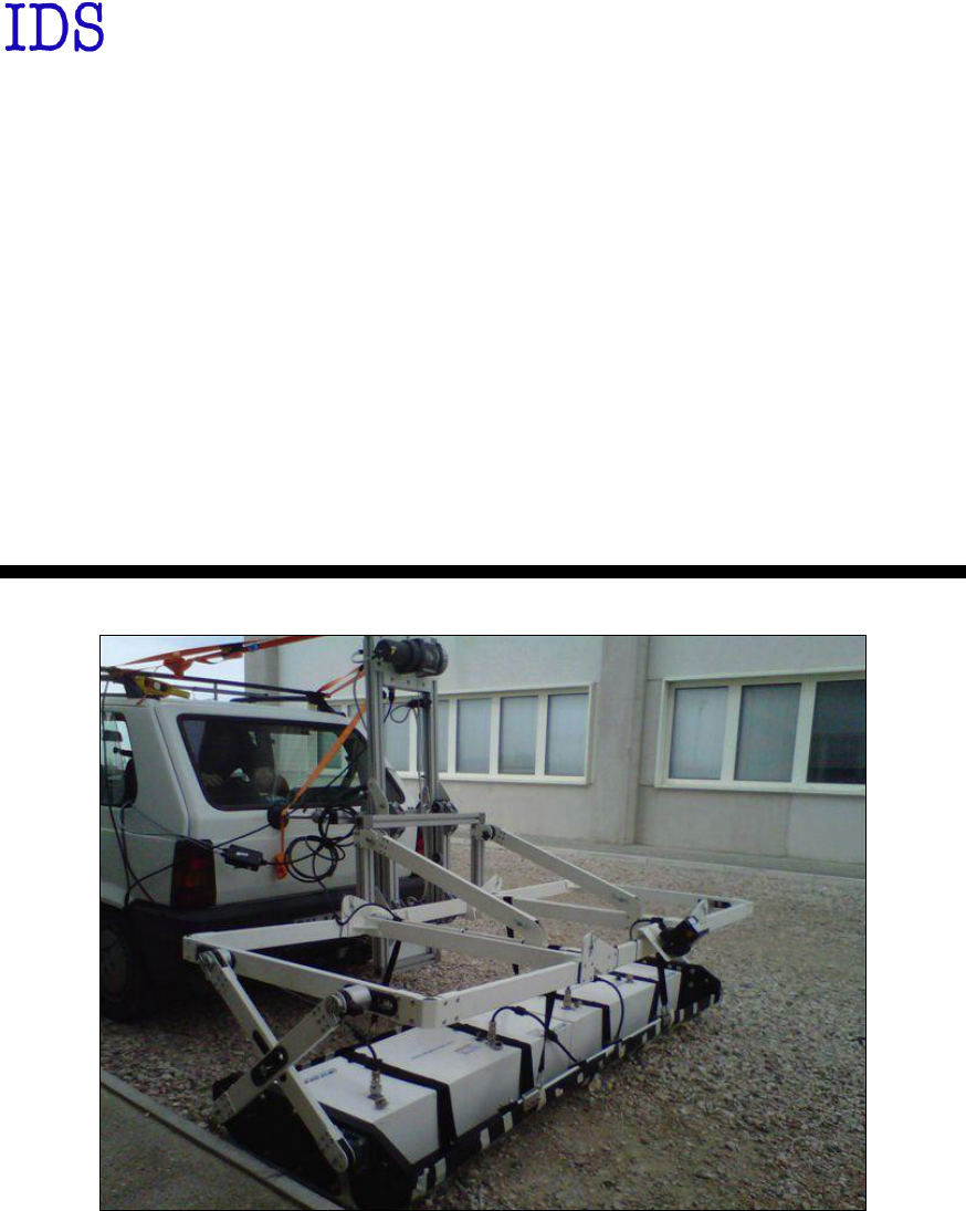
1. HARDWARE CONFIGURATION OF THE STREAM-X SYSTEM
The STREAM-X system consists of the following parts
DAD Fast Wave Control Units
1 Laptop
1 LAN Cable
2 Battery Cables (1 standard cable + 1 crocodile cable)
2 Batteries
1 Antenna-DAD Long Cable
1 Antenna Array (2 Modules @ 200MHz or 1 Module @ 600 MHz)
1 Black sledge (2 Modules with cross arms)
1 Antenna-Antenna Short Cable
1 White frame with Doppler encoder
1 Motor rack
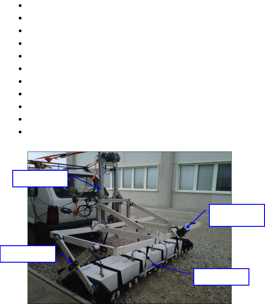
Fig. 1.1 – STREAM-X System in complete configuration
Motor rack
Doppler
Encoder
Cross arms
Antenna arrays
15/ 22
1.1 Assembly procedure of the System
In the following chapters the procedure to assemble the mechanical kit of Stream-
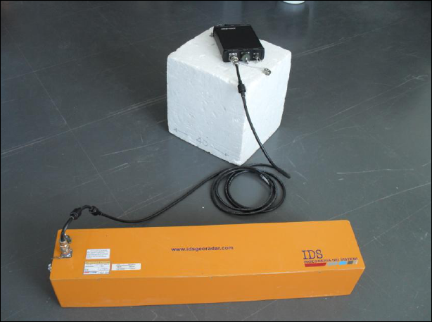
X will be explained. This procedure shows the assembling of the 200 MHz system
(AR200-V8 antennas). The 600 MHz antenna only difference is the use of the
AR600-V12 antenna model.
Fig. 1.2 – 600 MHz array (AR600-V12 model)
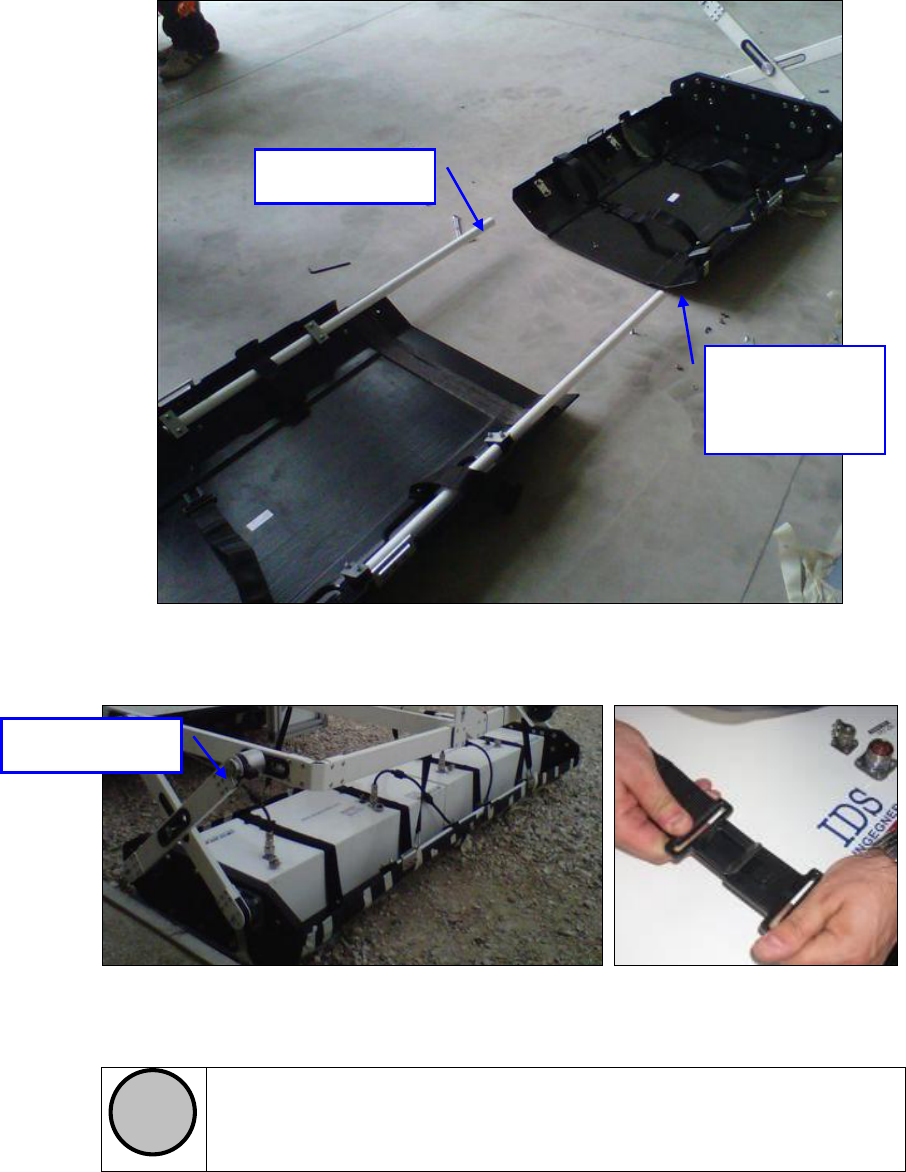
The black sledge is composed of two modules: link them with the white joints and
fix the structure with the dedicated screws (Fig. 1.3). Insert the antenna modules in
place and fix them with the elastic bands as shown in Fig. 1.4.
16/ 22
Fig. 1.3 – Stream X sledge kit
Fig. 1.4 – Antenna positioning
!
NOTE
Notice that antenna connectors are placed to be aligned with the arm in
the external side of the “cross”. This positioning must be done to
respect the standard configuration file of IDS acquisition software.
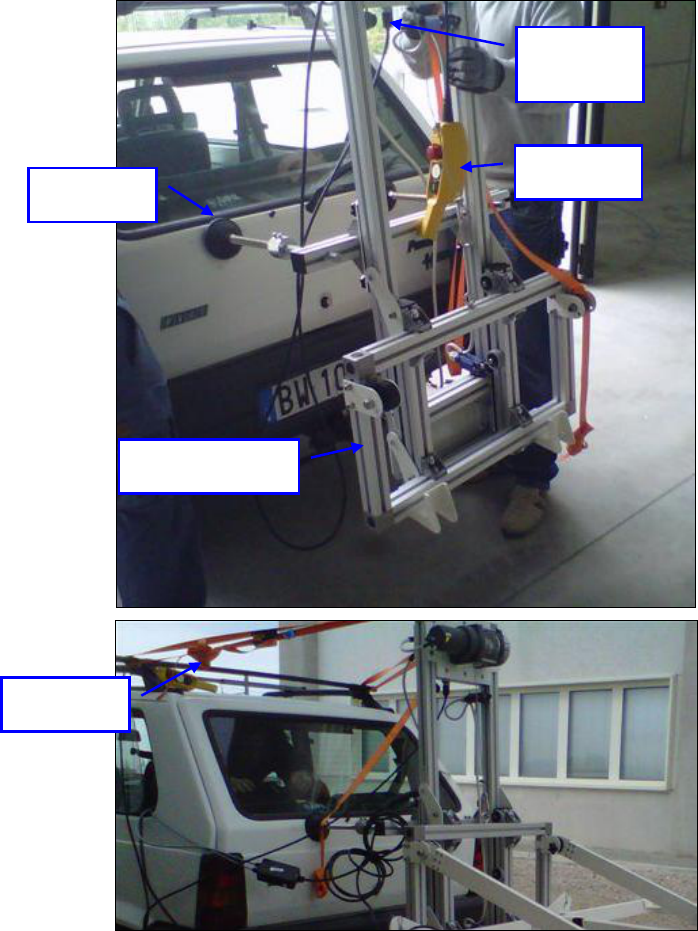
Put the motor rack over the hook linked to the vehicle with the automatic locking system
(Fig. 1.5). Unscrew the supports until they touch the vehicle and modify their extension
until the frame reaches approximately 90° with the ground level. Stabilize the frame
applying straps. Link the remote to the remote connector and the crocodile battery cable
to the bigger car battery supplied with the system (Red goes with +, Black goes with -).
This will let you activate the motor rack: place the moving frame in the lowest position.
Joints
Fixing
screws
External arm
17/ 22
Fig. 1.5 – Motor rack
Moving frame
Remote
Support
Remote
connector
Straps
18/ 22
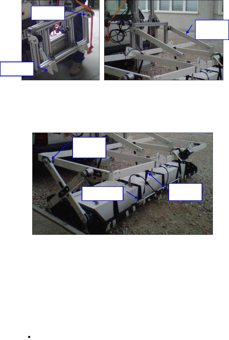
Fig. 1.6 – Fixing the white frame
When the rack is in place the white frame can be connected to it. Just put the central part
of the frame in the pivots of the rack and place the locking bars over the joints (Fig. 1.6).
Fig. 1.7 – Link to the antenna sledge
Use the four strips with karabiner to link the white frame with the metallic plates of the
antenna sledge (Fig. 1.7). Link the cross arms with their corresponding joints: to do this
operation easily, you may lift a little bit the sledge from the ground using the motor rack.
1.1.1 Cabling
In the following chapter you will find the description of the Stream X cabling. Your
system will be supplied with:
One 5m antenna cable: this one will connect ANT1 port of the DAD unit to IN
connector of the rightmost antenna frame (looking from behind).
Pivot
Locking
bar
Joint
Strip with
Karabiner
Metallic plate
Arms
joints
19/ 22
One 1.5m antenna cable: this one will connect the two modules of the array in
cascade (not required for the STREAMX600 system)
Three Doppler encoder cables: these unique shaped cables will link the encoder
with its piloting black box and the black box with both the wheel port of the DAD
and the radar battery (small one).
LAN cable: this cable connects the DAD to the laptop.
Crocodile cable: this cable is used to power the motor rack
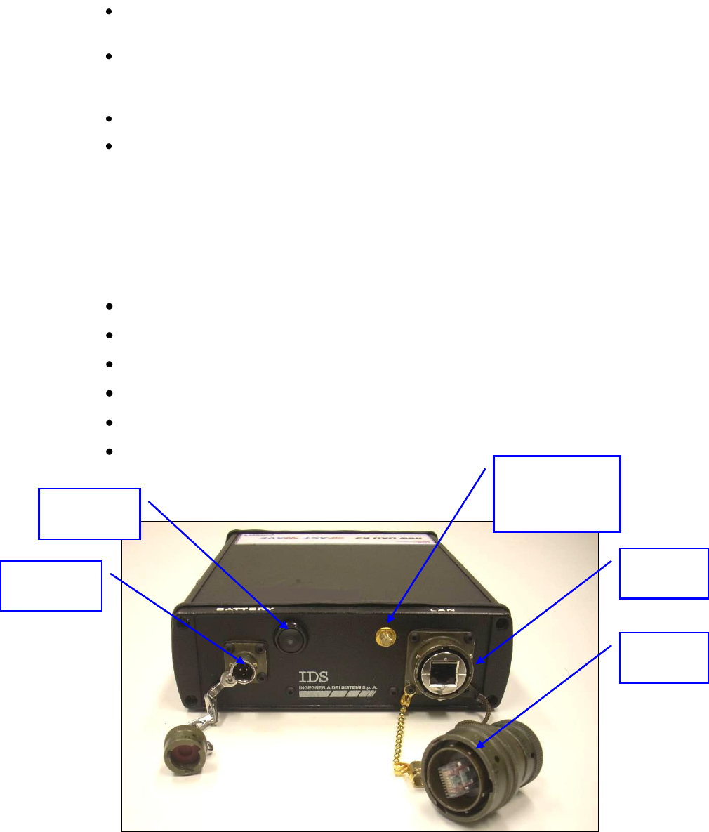
1.2 The DAD Fast Wave Control Units
The DAD Control Unit is the control unit responsible for directing the antennas
and digitalising the acquired radar data.
The DAD Control Unit has the following ports
Lan Port for a network connection to the Notebook Computer
Battery Port to connect the battery
Wheel Port to connect the position sensor wheel
Ant.1/CHAINE - Ant.2 for radar antenna connection
Power switch with pilot light
Wireless antenna connector
-
Fig. 1.8 – DAD side Fast Wave with Battery Port, Lan Port and wireless
connector
LAN port
Battery Port
Start up
button
Wireless
antenna
connector
Wireless
plug
20/ 22
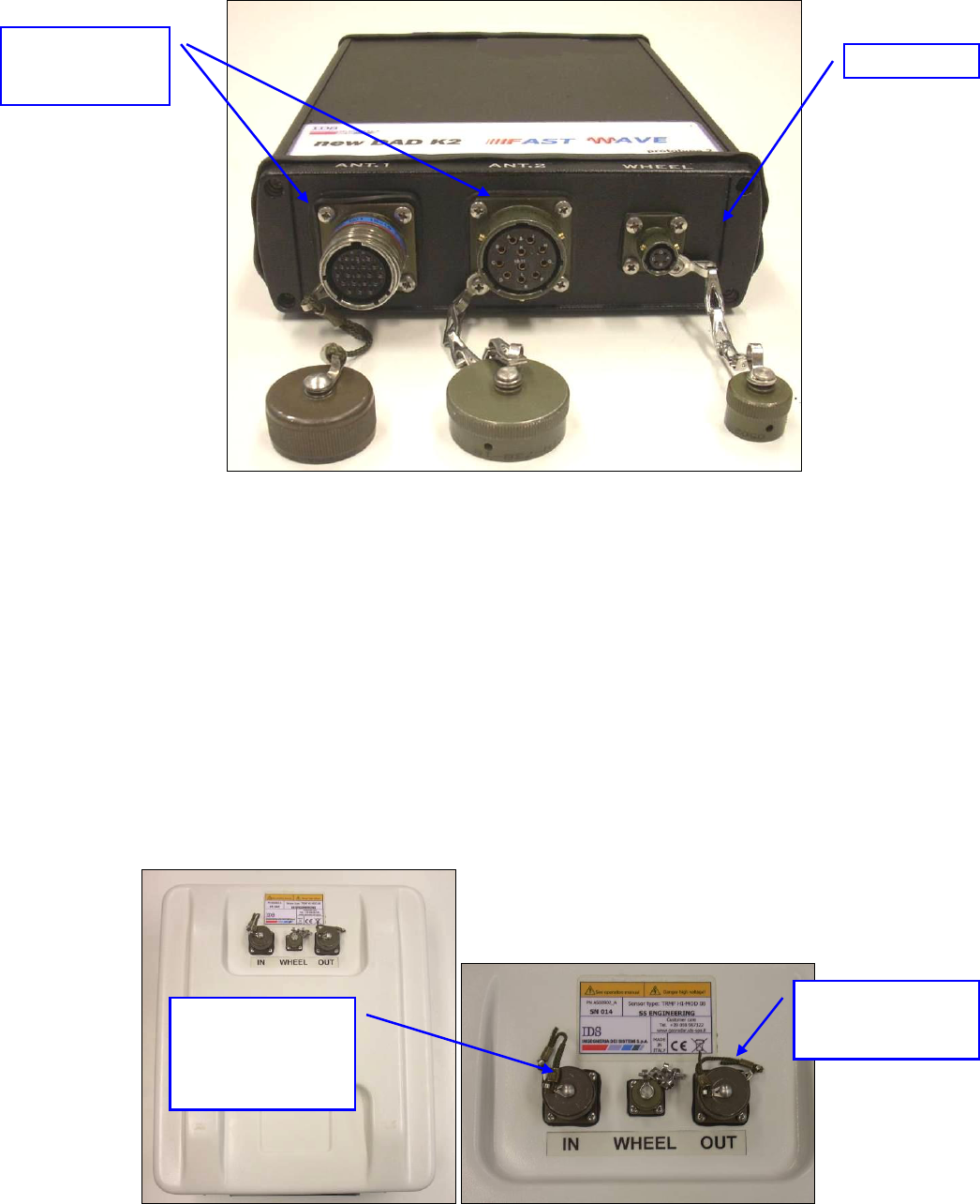
Fig. 1.9 – –DAD side Fast Wave with connections to position sensor and
antennae
Considering the type of available antenna, the following combinations are
possible:
1. Ant.1 (connector with 19 poles)
This kind of connector may be connected to the following categories of
radar antennae.
Entire range of TR IDS antennae that has a 19 pole connector and
foresee a cascade connection (including STREAMX200 and
STREAMX600 antennas); Fig. 2-3 shows an example of a an
antennae with a 19 pole connector with a cascade connection.
Fig. 1.10 – Example of antenna with a 19 pole connector and possibility of a
cascade connection
Ant1 and Ant 2
Connectors
Wheel Port
For DAD
connection or
toward another
antenna
To connect the
other antenna
21/ 22
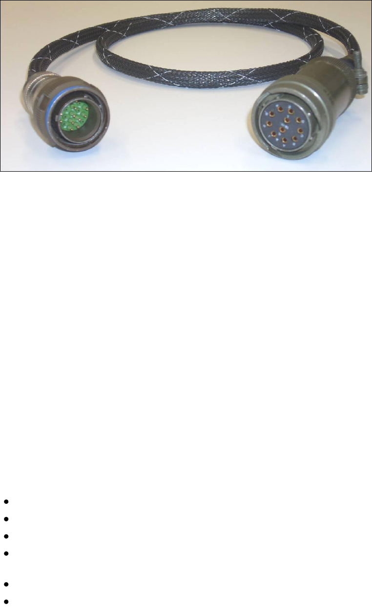
Entire range of TR IDS antennae that have an 11 pole connector, if
supplied with an appropriate 19-11 pole adaptor (Fig. 1.11).
Fig. 1.11 – 19-11 pole Adaptor
2. Ant.2 (11 pole connector)
This kind of connector may have the following antenna radar categories
connected
Entire range of mono static TR IDS antennae with an 11 pole
connector
Entire range of TR IDS antennae with internal or external
multiplex and an 11 pole connector
1.3 The Laptop Computer
The K2STREAM acquisition SW is installed on a Laptop. This SW is dedicated
to the specific phases of setting up, acquiring and saving radar data.
IDS recommends to use one of the two following laptops:
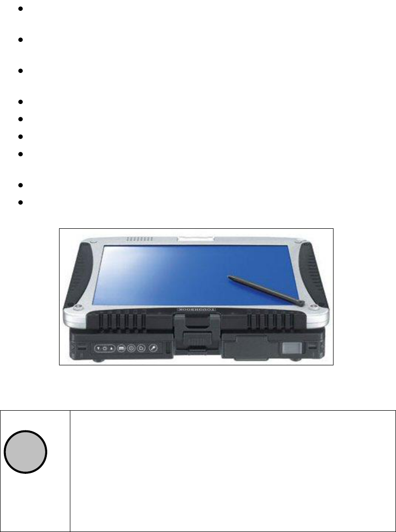
1.3.1 Panasonic Toughbook rugged tablet PC
The Panasonic Toughbook CF-19 PC (Fig. 1.12), has the following characteristics:
CPU: 1.6GHz Intel Core Duo.
Operating System: Windows XP Professional SP2.
RAM/Expandable to: 512MB SDRAM (DDR2)/4GB
Hard Drive/Speed: 80GB shock-proof (mounted on a gel support or
equivalent).
Optical Drive: 2.4X DVD+R DL
Display Resolution: 10.4 inches/1024 x 768
22/ 22
Graphics/Video Memory: Intel 945GM video accelerator with up to
128MB shared video memory
Wireless Networking: WLAN 802.11a/b/g, Bluetooth 2.0, Optional
WWAN (EVDO, HSDPA) and GPS
Ports: Two USB 2.0, Firewire, Ethernet, modem, headphone, mic, docking
connector
Card Slots: PC Card Type II, SD Card slot
Weight: 5 pounds
Size: 10.7 x 8.5 x 1.9 inches
Warranty/Support: Three-year limited warranty, parts and labor lifetime
toll-free 24/7.
Battery Life (Wi-Fi On/Off): 5h / 6h about
Environmental: Water-proof (IP54)
Fig. 1.12 – Panasonic Toughbook CF-19
!
NOTE
No communication software of the type Firewall, WiFi or
Antivirus protection may be installed on the computer; these types
of SW enter into conflict with the K2STREAM acquisition SW.
IDS takes no responsibility for any functional conflicts that may
occur between their own software and any other software installed
by the user onto the Laptop. IDS doesn’t guarantee that equipment
performance will be maintained using configurations different
from those recommended.