Inkel JR10 RF Repeater User Manual Manual
INKEL Corporation RF Repeater Manual
UserManual.wiki
>
Inkel
>
JR10 User Manual
Manual
Navigation menu
Upload a User Manual
Namespaces
Wiki Guide
HTML
PDF
Info
Views
User Manual
Discussion / Help
Navigation
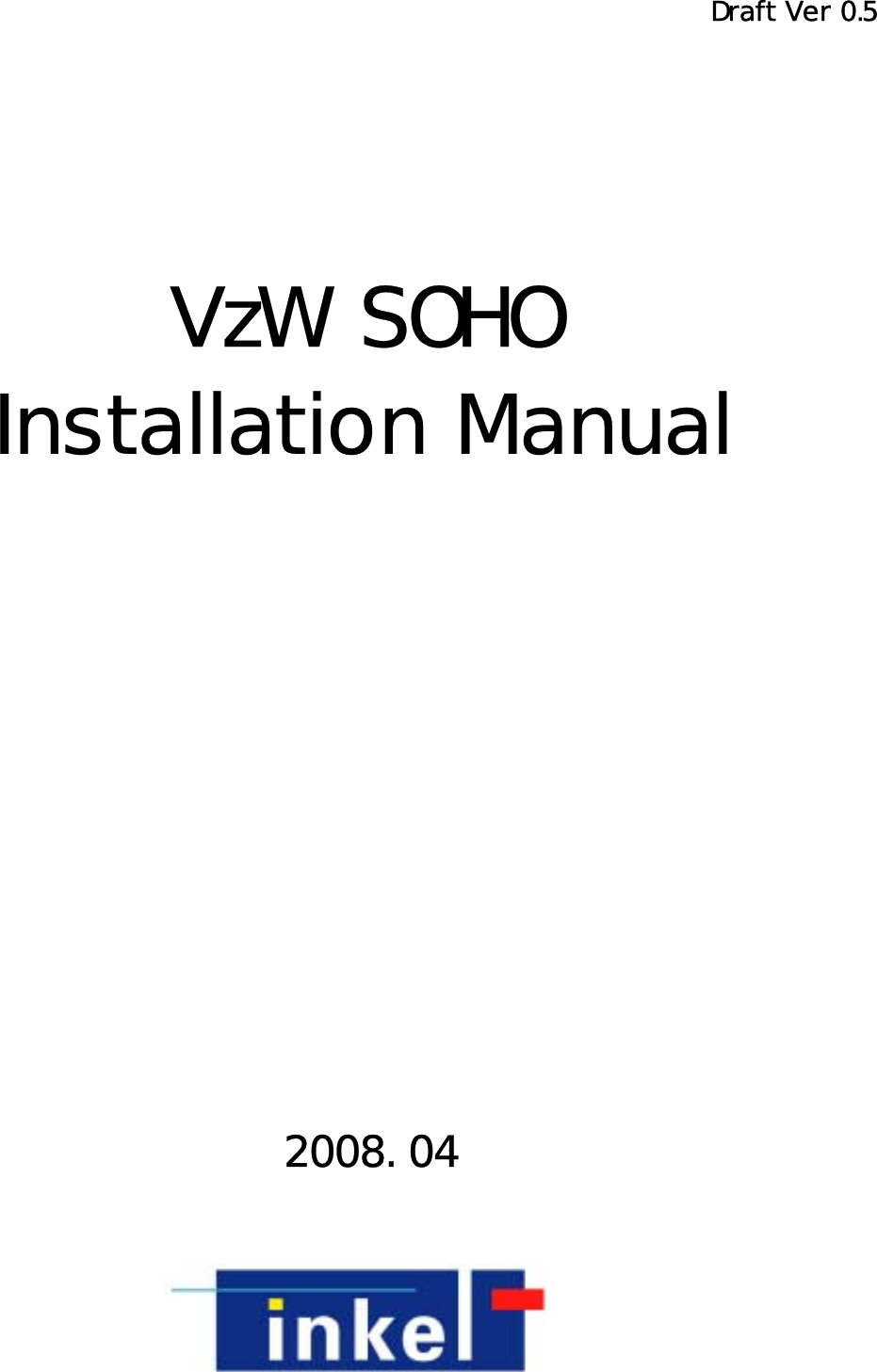


![165. LINK ANT. Installation 5.1 BRACKET/MTG Image 5.1.1. LINK ANTENNA 에 BRACKET – ANT Connection Image 1) The length unit is [mm]. Fig. 6 LINK ANT MTG BRACKET_ANT Connection Image 5.1.2. BRACKET/MTG Connection Image to Installation Place(WALL or POLE) ( Lumber Wall ) ( Concrete Wall ) ( Pole ) Fig. 7 WALL or POLE MTG BRACKET_ANT Connection Image](https://usermanual.wiki/Inkel/JR10/User-Guide-985446-Page-16.png)
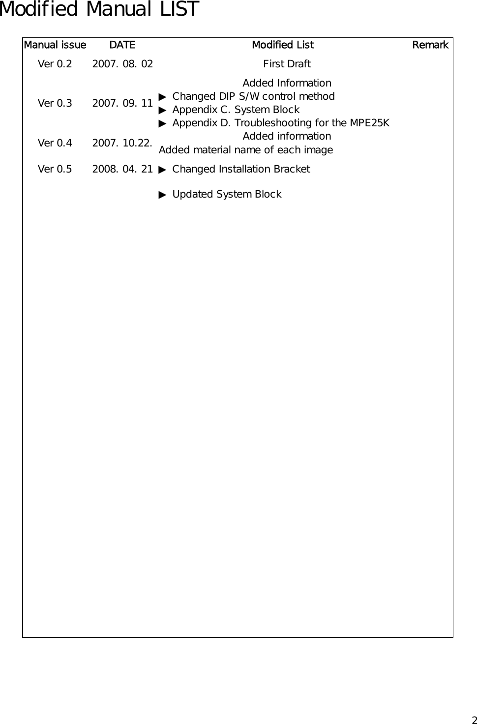
![175.2 LINK ANT MTG Bracket Connection 1) APPLY 1/4” NUT, SPRING WASHER, PLATE WASHER to LINK ANT. (Do not Connect Completely) 2) APPLY BRACKET-ANT TO LINK ANTENNA. 3) APPLY NUT COMPLETELY USING PROVIDED TOOL. [1/4” NUT, 1/4” SPRING WASHER, 1/4” PLATE WASHER 4ea, BRACKER-ANT 1ea] Fig. 8 LINK ANT 에 MTG BRACKET_ANT Connection Image](https://usermanual.wiki/Inkel/JR10/User-Guide-985446-Page-17.png)
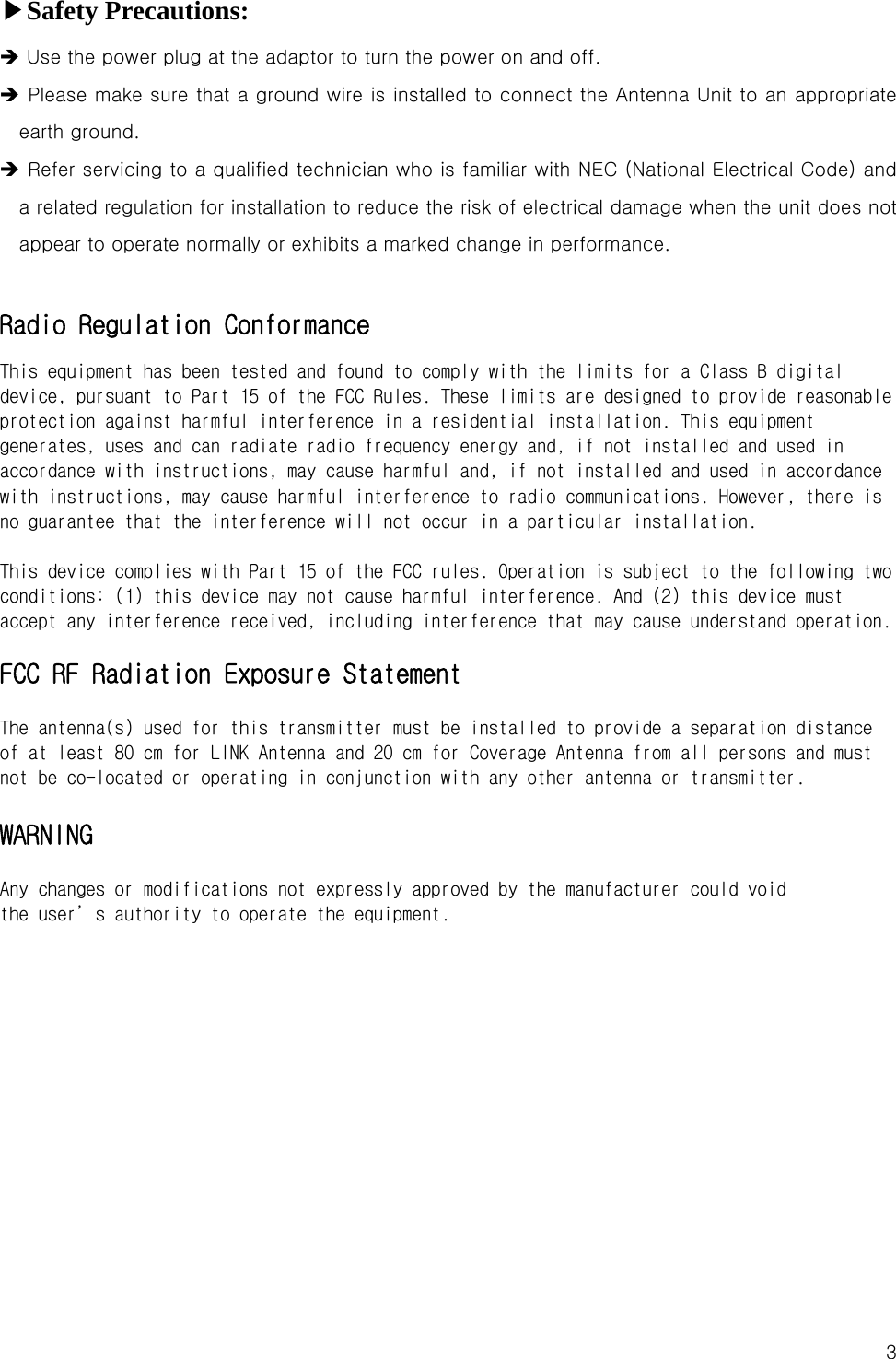
![185.3 BRACKET Connection depending on Installation Place 5.3.1. POLE MOUNTING 1) Secure DU to the pole using U-BOLT. 2) Insert U-BOLT to between BRACKET-POLE and BRACKET-DU 3) Apply the pole to the BRACKET-DU: use the nuts and u-bolts provided to fixate the bracket into the Pole. [BRACKET-ANT 1ea, BRACKET-POLE 2ea, U-Bolt 2ea, 1/4” NUT, 1/4” SPRING WASHER, 1/4” PLATE WASHER each 4ea] Fig. 9 POLE MOUNTING MTG BRACKET_ANT Connection Sequence 5.3.2. LUMBER WALL MOUNTING 1) Secure BRACKET-DU to the wooden wall. Using cross driver connect SCREW to wooden wall through BRACKET-DU. [BRACKET-ANT 1ea, SCREW (TH+ TS-1 5x30L) 4ea] Fig. 10 LUMBER WALL MOUNTING MTG BRACKET_ANT Connection Sequence](https://usermanual.wiki/Inkel/JR10/User-Guide-985446-Page-18.png)
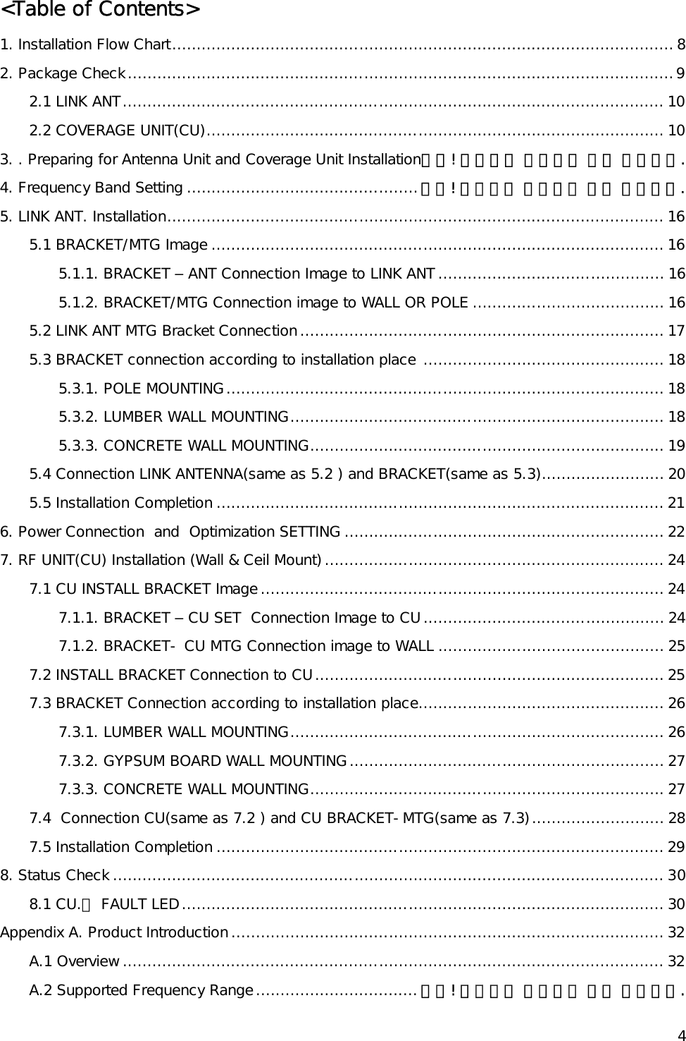
![195.3.3. CONCRETE WALL MOUNTING 1) Drill on the wall as the BRACKET-ANT distance.(forφ 10mm Hole depth to be 30 to 40 mm. 2) INSERT SET-ANCHOR TO DRILLED HOLE. 3) Secure BRACKET-DU to the Wall and fix the nut. [SET-ANCHOT 4ea, BRACKER-ANT 1ea] Fig. 11 CONCRETE WALL MOUNTING MTG BRACKET_ANT Connection Sequence](https://usermanual.wiki/Inkel/JR10/User-Guide-985446-Page-19.png)
![205.4 LINK ANTENNA Connection (same as 5.2) with BRACKET (same as 5.3) 1) APPLY LINK ANTENNA to the BRACKET. 2) Apply the NUT to the upside of BRACKET like below sequence. – Do not apply the NUT completely. 3) Set the receiving direction of the ANTENNA and apply the NUT completely using the provided tool. [1/4” NUT, 1/4” SPRING WASHER, 1/4” PLATE WASHER 각 4ea] Fig. 12 LINK ANT Connection Sequence to Installed MTG BRACKET-ANT](https://usermanual.wiki/Inkel/JR10/User-Guide-985446-Page-20.png)
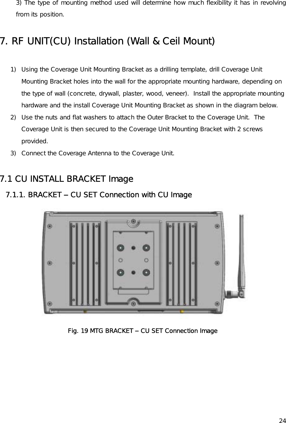
![257.1.2. BRACKET- CU MTG Connection to Wall Image Fig. 20 MTG BRACKET – CU Connection Image 7.2 INSTALL BRACKET Connection to CU 1) Apply BRACKET – SET to CU completely using NUT, SPRING and PLATE WASHER. 2) Apply SCREW to BRACKET – SET suitably. (not completely) [CU BRACKET-SET 1ea, BRACKET SCREW 2ea, NUT, SPRING WASHER, PLATE WASHER 각 4ea]](https://usermanual.wiki/Inkel/JR10/User-Guide-985446-Page-25.png)
![26 Fig. 21 MTG Bracket – CU SET Connection Sequence 7.BRACKET Connection depending on Installation Place 7.3.1. LUMBER WALL MOUNTING 1) Secure BRACKET-CU MTG to the wooden wall. Using cross driver, connect completely SCREW to wooden wall through BRACKET-MTG. [CU BRACKET-MTG 1ea, SCREW 4ea] Fig. 22 LUMBER WALL MTG Bracket MOUNTING](https://usermanual.wiki/Inkel/JR10/User-Guide-985446-Page-26.png)
![277.3.2. GYPSUM BOARD WALL MOUNTING 1) Secure DRYWALL anchor to the GYPSUM BOARD WALL using cross driver completely. 2) Secure DRYWALL anchor screw to BRACKET – CU MTG using cross driver completely. [BRACKET-CU MTG 1ea, Drywall Anchor 4ea, Screw 4ea] Fig. 23 GYPSUM BOARD WALL MTG Bracket MOUNTING 7.3.3. CONCRETE WALL MOUNTING 1) Secure PLASTIC ANCHOR TO WALL. (Removal is impossible after connection.) : INSERT PLASTIC ANCHOR after drill φ 6mm Hole in the wall by 30~40mm depth [CU BRACKET-MTG 1ea, PLASTIC ANCHOR 4ea] Fig. 24 CONRETE WALL MTG Bracket MOUNTING](https://usermanual.wiki/Inkel/JR10/User-Guide-985446-Page-27.png)
![287.4 Connection CU(same as 7.2) with CU BRACKET-MTG(same as 7.3) 1) APPLY CU to BRACKET-CU MTG. 2) After securing CU to Wall, connect the SCREW (M4X12L SEMS) to the BRACKET. [SCREW(M4X12L SEMS) 2ea] Fig. 25 CU Connection to Installed BRACKET –CU MTG Sequence](https://usermanual.wiki/Inkel/JR10/User-Guide-985446-Page-28.png)