IR TEC DP363 360 Degree Ceiling Mount Dual-Tech Motion Detector User Manual 1 rev
Ir Tec International Ltd 360 Degree Ceiling Mount Dual-Tech Motion Detector 1 rev
IR TEC >
Contents
- 1. User manual 1 rev
- 2. User manual 2
User manual 1 rev
R
360° Ceiling Mount PIR+MW Dual-Tech Motion Detector
DP-363
Installation Instructions
GENERAL
Thank you for choosing IR-TEC dual technology
motion detector for your security system. The DP-363
is a 360° ceiling mount motion detector that combines
a passive infrared (PIR) and a DRO microwave (MW)
motion sensor in a sleek housing. It utilizes AND logic
discretion and advanced signal processing to provide
superior intrusion detection reliability. To achieve the
best detection, please read all instructions thoroughly
prior to installation.
INSTALLATION HINTS
1. The DP-363 should be mounted on a firm section
of ceiling and located for optimum coverage.
2. Do not install where the detector is exposed to
direct or mirror-reflected sunlight.
3. Make sure the detection area does not have
obstruction which may block the detection zones.
4. Avoid running the alarm cable along with AC
mains cable to prevent EMI.
5. Locate the detector at least 0.3 m (1ft) away from
fluorescent light to avoid possible interference to
the microwave sensor.
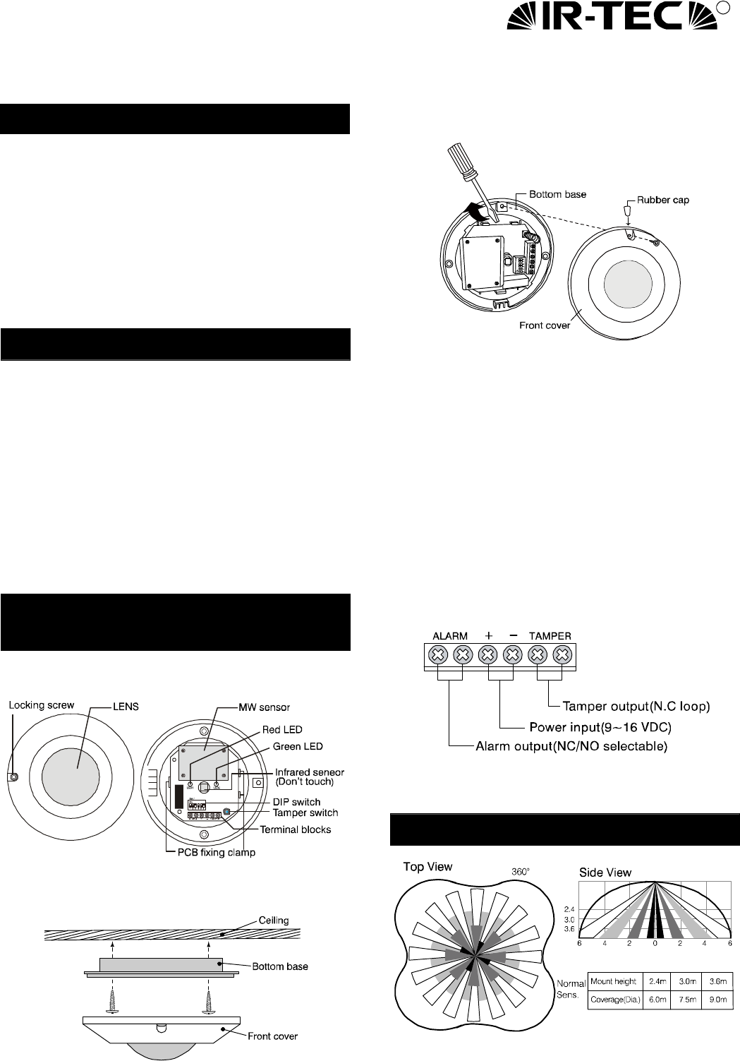
INTERNAL
VIEW/INSTALLATION
Internal View
Installation Illustration
PCB Disassembly Diagram
Description
1. Loosen the cover locking screw, open the cover.
2. Refer to the PCB disassembly diagram, carefully
remove the PC board from the bottom base.
3. Knockout the adequate cable access and mounting
holes on the bottom base.
4. Lead the alarm cable through the access hole, and
mount the bottom base at the selected location.
5. Replace the PCB at the bottom case. Connect the
signal wires with the terminals according to the
wiring diagram as below.
6. Replace the front cover and then walk test can be
conducted.
Wiring Diagram
Warning: TAMPER output should connect with the
24- hour N.C supervised loop of control panel.
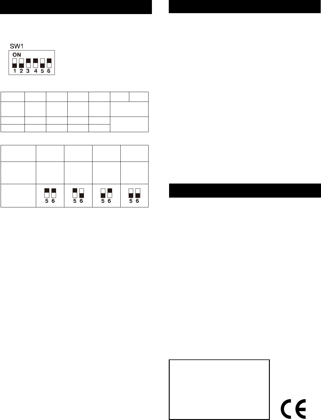
DETECTION PATTERN
FUNCTION SETTING
SW1 DIP switch is available for all function settings of
the detector. Please refer to the following instructions
for setting options.
Function Setting Indication
SW# 1 2 3 4 5 6
Function
Setting
Pulse
Count
Trigger
Count
LED
ON/OFF
Alarm
Output
MW Sensitivity
ON 3 ON ON NC
OFF 1 OFF OFF NO
(Refer to next
table)
Microwave Sensitivity Setting
MW
Sensitivity
60% 80% 100% 120%
Detection
Coverage
(@3m high)
4x4m 6x6m 8x8m
(default)
12x12m
Switch
Setting
1. Pulse Count
The DP-363 features intelligent pulse count in its PIR
sensor which can effectively prevent false alarms
cause by environmental interference. If it is installed at
the places with rapid temperature change or unknown
electrical interference, DIP switch #1 which controls
the PIR pulse count can be set to ON position for 3
pulses to increase the detection reliability.
2. Trigger Count
When pulse count is already set on, and the detector
still experiences false alarm caused by unknown factor,
then “Trigger Count” can be enabled. With trigger
count enabled, the detector will hold the alarm output
for a short period of time and release the alarm signal
only when a true intrusion is verified by sophisticated
signal processing software.
Warning: Once the trigger count is enabled, the
alarm output will be slower than normal. Thus,
walk test must be conducted to ensure that
detector not to miss catching the intrusion.
3. LED Indication
The LED of DP-363 indicates the operation status of
the detector. When the green LED lights up, it means
the MW sensor is active. When the red LED lights up,
it shows the alarm output (also represents the infrared
sensor is active). If it is necessary to disable the LED
indication, just set DIP switch #3 to OFF position.
WALK TEST & ADJUSTMENT
Please refer to the following instructions to conduct
walk test and MW adjustment.
Walk Test
1. Apply DC power supply and wait about 60
seconds for sensor to warm up. During warm up
period, both red and green LEDs will light up.
2. After the warm up time expires, walk across the
detection area at normal speed. Check if the red
and green LED turn on/off following by tester’s
walk/stop.
Sensitivity Adjustment
If there is no movement within the detection range and
the green LED remains on, this means that MW sensor
is probably over sensitive (usually appears in a smaller
room). Please reduce the MW sensitivity in
accordance with the MW sensitivity setting table.
Note: Regular walk test must be carried out, as
part of routine maintenance at least once a year.
The mounting height should be at least at 2.4m.
SPECIFICATIONS
MW frequency 10.525GHz
MW output power 10dBm EIRP
Power supply 9~16VDC (12 VDC nominal)
Current drain 17mA@12VDC
Infrared sensor Omni-directional, dual element,
low noise
Microwave sensor DRO w/m micro strip antenna
Mounting height 2.4~3.6m
Alarm period 2~4 sec.
Alarm output NC/NO, selectable, 30VDC,
0.2A max.
Warm up period 60sec.Red/Green LED on
Alarm output LED Red, can be disabled
MW sensor LED Green, can be disabled
Tamper protection NC, cover open activates
Pulse count PIR 1/3, selectable
Op. temperature -20°C~ 55°C (-4°F~131°F)
Dimensions 110 (dia.) x 44mm (H)
06/07’ 058-36321-001
FCC ID: NRIDP363
This device complies with Part 15 of the FCC Rules.
Operation is subject to the following two conditions:
(1) This device may not cause harmful interference,
and
(2) This device must accept any interference received,
Including interference that may cause undesired
operation.
l The black blocks
indicate switch position.
l The left shows factory
default setting.
Note:
1.Any changes of modifications not expressly
approved by the grantee of this device could
void the user’s authority to operate the
equipment.
2.This equipment has been tested and found to
comply with the limits for a Class B digital
device, pursuant to Part 15 of the FCC Rules.
These limits are designed to provide reasonable
protection against harmful interference in a
residential installation. This equipment
generates, uses and can radiate radio frequency
energy and, if not installed and used in
accordance with the instructions, may cause
harmful interference to radio communications.
However, there is no guarantee that interference
will not occur in a particular installation.
If this equipment does cause harmful
interference to radio or television reception,
which can be determined by turning the
equipment off and on, the user is encouraged to
try to correct the interference by one or more of
the following measures:
-- Reorient or relocate the receiving antenna.
-- Increase the separation between the
equipment and receiver.
-- Connect the equipment into an outlet on a
circuit different from that to which the receiver
is connected.
-- Consult the dealer or an experienced radio/TV
technician for help.