Ideal Lighting CREE Lighting RFM RFM MODULE User Manual CR Fixture
Cree, Inc RFM MODULE CR Fixture
Contents
- 1. User Manual_CR Fixture
- 2. User Manual_CS Fixture
- 3. User Manual_C.-RF Module
User Manual_CR Fixture
CR Series with Cree SmartCast™ Technology
CR14™, CR24™, CR22™ LED Architectural Troffers
1x4, 2x4, 2x2 Luminaires
1 of 3 LPN00212X0002A7
INSTALLATION INSTRUCTIONS
INSTRUCTIONS D’INSTALLATION
IMPORTANT SAFEGUARDS
When using electrical equipment, basic safety precautions
should always be followed including the following:
READ AND FOLLOW ALL SAFETY
INSTRUCTIONS
1. DANGER- Risk of shock- Disconnect power before
installation.
DANGER – Risque de choc – Couper l’alimentation
avant l’installation.
2. This luminaire must be installed in accordance with
the NEC or your local electrical code. If you are not
familiar with these codes and requirements, consult a
qualied electrician.
Ce produit doit être installé conformément à NEC ou
votre code électrique local. Si vous n’êtes pas familier
avec ces codes et ces exigences, veuillez contacter un
électricien qualié.
3. Do not handle energized module with wet hands or
when standing on wet or damp surfaces, or in water.
4. Suitable for damp locations.
Convient aux emplacements humides.
5. Access above ceiling required. Do not install insulation
within 3" (76mm) of any part of the luminaire.
Accès requis au-dessus du plafond. Ne pas mettre
l’isolant à moins de 76 mm (3 po) de toute partie du
luminaire.
6. Suitable for suspended ceilings.
SAVE THESE INSTRUCTIONS FOR FUTURE
REFERENCE
TO INSTALL:
LUMINAIRE INSTALLATION
STEP 1:
Unpack the CR troffer from its
shipping container.
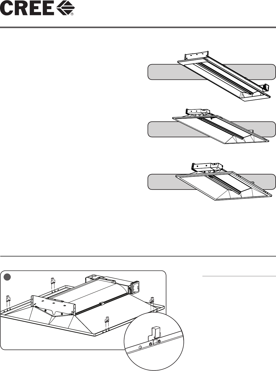
STEP 2:
Install the (4) T-Bar clips included
with the luminaire (located in
pre-pack fastened to luminaire
junction box). See Figure 1.
1
• The CR Series of recessed troffers is for non-insulated ceiling applications using T-Bar ceiling grid and drywall grid adaptors.
• Designed for use in 120-277V 50-60 Hertz protected circuit (fuse box, circuit breaker). Supply wire sized as per NEC or
governing code(s), 90° C rated.
CR14
CR24
CR22
2 of 3 LPN00212X0002A7
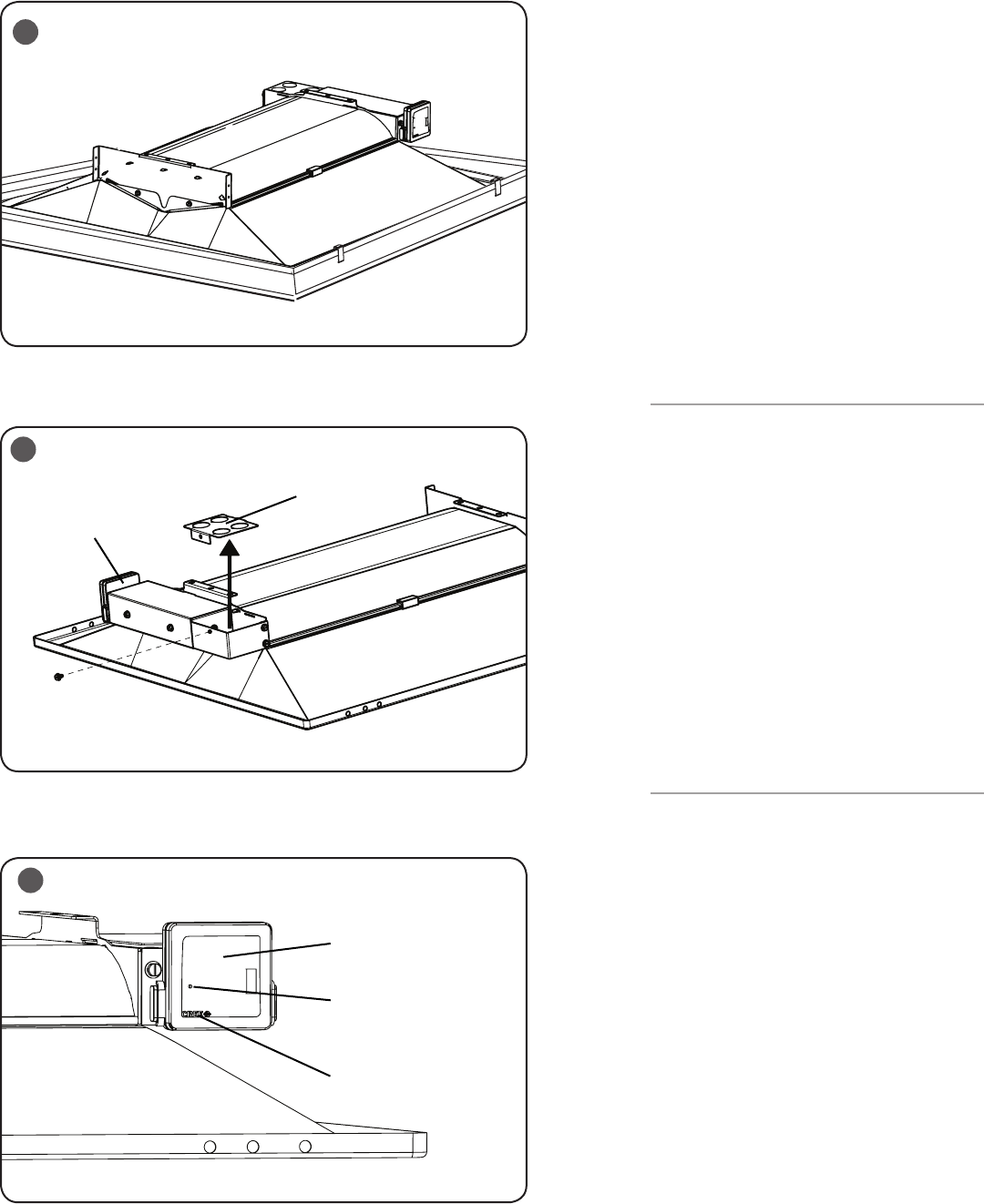
STEP 3:
Place the CR troffer into the T-Bar Ceiling
panel. Ensure T-Bar clips are attached to the
T-Bar. See Figure 2.
STEP 4:
Remove access plate from junction box.
Using screw driver blade, remove appropriate
knockout from access plate door to route
input conduit. See Figure 3.
STEP 5:
Connect input conduit to access plate.
Make wiring connections per Electrical
Connections section. Push all wires back into
the junction box.
STEP 6:
Re-install access plate that was removed in
Step 4.
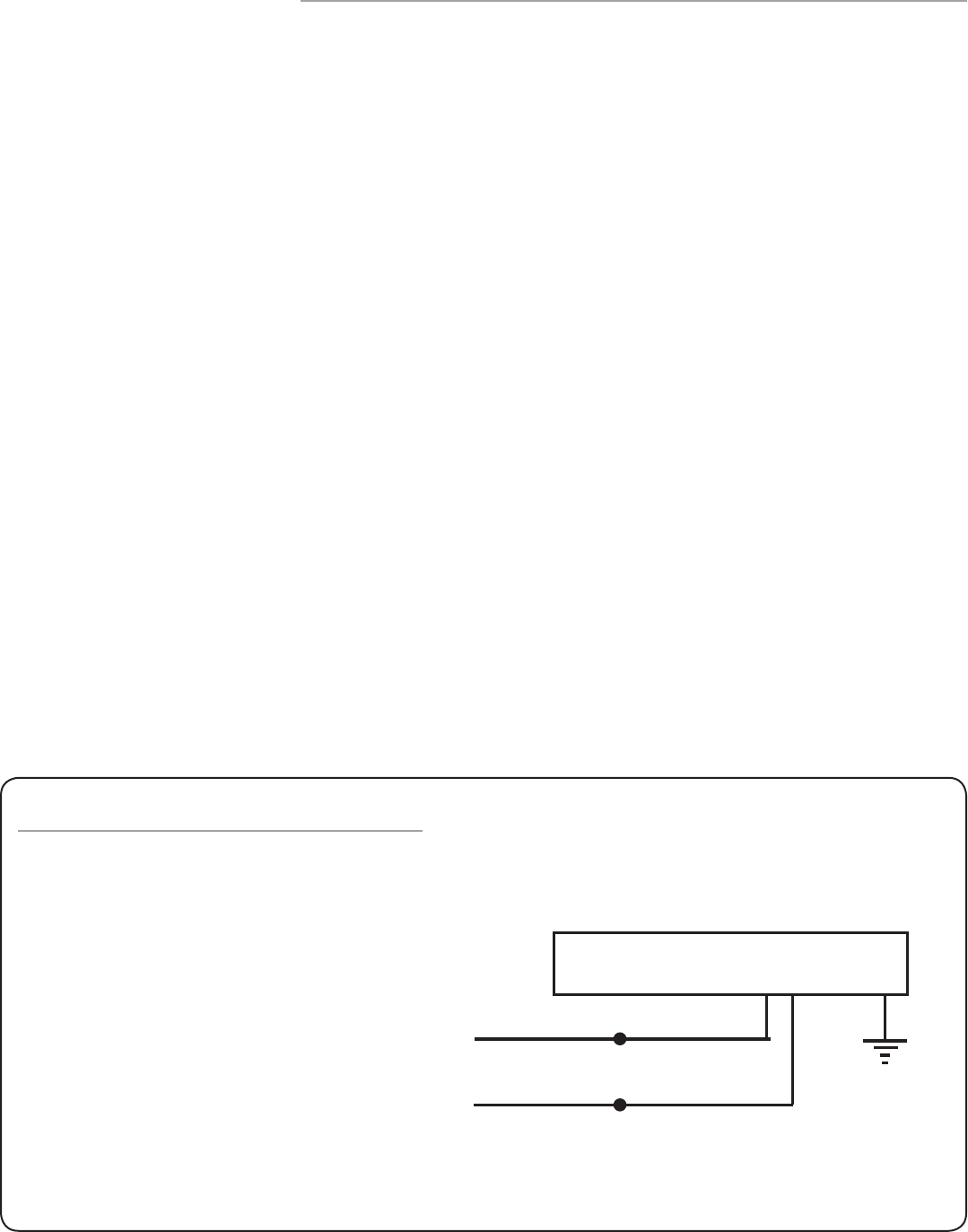
RESET RF MODULE
NOTE: The Blue LED is located behind the
CREE logo on the RF Module. The CREE logo
with illuminate blue when the Blue LED is
active.
STEP 1:
Actuate RESET button through the access
hole. Push and hold until LED on RF module
begins blinking rapidly (approximately 6-7
seconds). See Figure 4.
STEP 2:
Release for 1 sec.
STEP 3:
Press/Hold RESET button for 0.5 sec. Light
will turn off for a few seconds then go to full
bright and the Blue LED on the RF Module
should begin a 2 blink sequence. Figure 4.
TROUBLESHOOTING:
Out of the box, if the light does not turn on
when power is applied:
• Check Wiring with power off
• If wired correctly, check to see if Blue
LED blinking on the RF Module.
• If Blue LED is blinking, then perform a
RESET
(See RESET RF MODULE section).
• If Blue LED is on solid or off, call Cree
Customer Service.
• If you have done a RESET, and the light
is still off, call Cree Customer Service.
If light is unresponsive, use Cree
Configuration Tool to verify configuration.
3
4
Access Plate
RF Module
RF Module
Access Hole, Reset Button
Inside
Blue LED
Placement
2
3 of 3 LPN00212X0002A7
ELECTRICAL CONNECTIONS
STEP 1:
Make the following Electrical Connections :
a. Connect the black fixture lead to
the voltage supply position.
b. Connect the white fixture lead to
the neutral supply position.
c. Connect the green ground lead to
the green wire position.
LINE
DRIVER ASSEMBLY
BLACK
WHITE
NEUTRAL
FCC NOTICE
To comply with the FCC RF exposure compliance requirements, this device and its antenna
must not be co-located or operating to conjunction with any other antenna or transmitter.
This equipment should be installed and operated with minimum distance 5cm between the
radiator & your body.
FCC COMPLIANCE STATEMENT
CAUTION: Changes or modifications not expressly approved could void your authority to use
this equipment.
This device complies with Part 15 of the FCC Rules. Operation to the following two conditions:
(1) This device may not cause harmful interference, and (2) this device must accept any
interference received, including interference that may cause undesired operation
This device has been tested and found to comply with the limits for a Class A digital device,
pursuant to Part 15 of the FCC Rules. These limits are designed to provide reasonable
protection against harmful interference when the device is operated in a commercial
environment. This device generates, uses, and can radiate radio frequency energy and, if not
installed and used in accordance with the instruction manual, may cause harmful interference
to radio communications. Operation of this device in a residential area is likely to cause
harmful interference in which case the user will be required to correct the interference at his
own expense.
The LED in the front of this device operates within Risk Group 1 levels per IEC 62471.
INDUSTRY CANADA STATEMENT
This device complies with Industry Canada licence-exempt RSS standard(s). Operation is
subject to the following two conditions: (1) this device may not cause interference, and (2)
this device must accept any interference, including interference that may cause undesired
operation of the device. In addition, this device complies with ICES-003 of the Industry
Canada (IC) Regulations.
Le présent appareil est conforme aux CNR d’Industrie Canada applicables aux appareils
radio exempts de licence. L’exploitation est autorisée aux deux conditions suivantes : (1)
l’appareil ne doit pas produire de brouillage, et (2) l’utilisateur de l’appareil doit accepter tout
brouillage radioélectrique subi, même si le brouillage est susceptible d’en compromettre le
fonctionnement.