Image Sensing Systems RTMS-K4S RTMS K4 User Manual
Image Sensing Systems, Inc. RTMS K4
User Manual

RTMS® G4™ User Manual Version 5.5 ©Nov, 2011 PN2620-00C
RTMS® G4™
User Manual

Table of Contents
RTMS® G4™ User Manual © 2010 Image Sensing Systems, Inc. b
Copyright 2008-2010 Image Sensing Systems, Inc. All Rights Reserved.
RTMS is a registered trademark of Image Sensing Systems, Inc.
No part of this document may be reproduced or quoted without written permission from Image
Sensing Systems, Inc.
Windows is a registered trademark of Microsoft Corporation.
All other product names are trademarks or registered trademarks of their respective owners.

RTMS® G4™ User Manual © 2010 Image Sensing Systems, Inc. i
Table of Contents
CHAPTER 1 ABOUT THE G4 SYSTEM ............................................................................... 1-1
REVISION HISTORY ....................................................................................................................... 1-1
WARRANTY ................................................................................................................................... 1-1
CAUTION .................................................................................................................................... 1-1
SERVICE ........................................................................................................................................ 1-2
PREREQUISITES ............................................................................................................................. 1-2
IMPORTANT SAFETY INFORMATION.............................................................................................. 1-3
CONTACT ISS CANADA................................................................................................................. 1-3
BRIEF DESCRIPTION ...................................................................................................................... 1-3
SCOPE OF THIS DOCUMENT .......................................................................................................... 1-4
INSPECT YOUR SHIPMENT FROM ISS CANADA ............................................................................. 1-4
RTMS OPTIONS ............................................................................................................................ 1-5
THE STANDARD RTMS G4 MODEL K4 OFFERS THE FOLLOWING: ................................................ 1-5
INTRODUCTION TO THE RTMS ..................................................................................................... 1-5
VEHICLE DETECTION .................................................................................................................... 1-6
CHAPTER 2 RTMS G4 INSTALLATION ............................................................................. 2-1
SIDE-FIRED MOUNTING AND AIMING ........................................................................................... 2-1
MOUNTING AND AIMING PROCEDURE .......................................................................................... 2-2
SET-BACK HEIGHT DIAGRAMS ..................................................................................................... 2-3
ZERO SETBACK OPTIONS .............................................................................................................. 2-3
CABLING ....................................................................................................................................... 2-4
Surge Suppression ..................................................................................................................... 2-4
The RTMS Cable ....................................................................................................................... 2-4
Preparing a Cable ..................................................................................................................... 2-4
Connecting a Cable to the RTMS .............................................................................................. 2-5
MS CONNECTOR PIN-OUT ............................................................................................................ 2-5
STANDARD RS-232 PORT WIRING ................................................................................................ 2-7
THE RS-485 PORT ......................................................................................................................... 2-8
THE TCP/IP PORT WITH RS-232 ................................................................................................... 2-9
THE TCP/IP PORT WITH RS-485 ................................................................................................. 2-10
DUAL RS-232 PORTS .................................................................................................................. 2-11
CONTACT CLOSURE .................................................................................................................... 2-12
CONNECTING RTMS TO EXTERNAL MODEMS ........................................................................... 2-12
Modem Cables ........................................................................................................................ 2-12
MODEM SHARING ....................................................................................................................... 2-13
RS-485 MULTI-DROP .................................................................................................................. 2-14
WIRING NOTES ............................................................................................................................ 2-15
RTMS TROUBLESHOOTING GUIDE ............................................................................................. 2-15
RTMS TECHNICAL SPECIFICATIONS .......................................................................................... 2-17
MICROWAVE SIGNAL AND COVERAGE AREA ............................................................................. 2-17
ACCURACY OF MEASUREMENT & ERROR RATES ....................................................................... 2-17
*Accuracy Performance Conditions ....................................................................................... 2-17
MECHANICAL .............................................................................................................................. 2-18
POWER REQUIREMENTS & CONSUMPTION ................................................................................. 2-18
INTERFACES ................................................................................................................................ 2-18
UPGRADE CAPABILITY ................................................................................................................ 2-18

Table of Contents
RTMS® G4™ User Manual © 2010 Image Sensing Systems, Inc. ii
SURGE IMMUNITY ....................................................................................................................... 2-19
ENVIRONMENTAL CONDITIONS .................................................................................................. 2-19
ELECTROMAGNETIC INTERFERENCE ........................................................................................... 2-19
RELIABILITY ............................................................................................................................... 2-19
RECOMMENDED SURGE PROTECTION ......................................................................................... 2-20
CHAPTER 3 G4 SOFTWARE.................................................................................................. 3-1
REFERENCE ................................................................................................................................... 3-1
RTMS System Requirements ...................................................................................................... 3-1
About The RTMS Setup Utility .................................................................................................. 3-1
Communication ......................................................................................................................... 3-1
PROCEDURES ................................................................................................................................. 3-1
MICROSOFT .NET RUNTIME WARNINGS ...................................................................................... 3-2
HOW TO NAVIGATE THE RTMS INTERFACE ................................................................................. 3-3
GET STARTED ............................................................................................................................... 3-4
ESTABLISH A CONNECTION WITH THE RTMS HARDWARE .......................................................... 3-4
HOW TO RUN WINRTMS IN DEMO MODE ................................................................................... 3-5
HOW TO MODIFY OR TROUBLESHOOT THE CONNECTION WITH THE RTMS HARDWARE .......... 3-10
HOW TO SET UP SERIAL COMMUNICATION ................................................................................ 3-12
HOW TO SET UP DSS .................................................................................................................. 3-13
HOW TO SET UP TCP/IP COMMUNICATIONS .............................................................................. 3-17
HOW TO SET UP BLUETOOTH DEVICE COMMUNICATIONS......................................................... 3-24
Configuring the Bluetooth Device ........................................................................................... 3-24
HOW TO CONFIGURE THE IP SERVER.......................................................................................... 3-29
HOW TO USE THE AUTOMATIC SETUP WIZARD ......................................................................... 3-30
HOW TO FIX SPLASHING ............................................................................................................. 3-33
HOW TO ADJUST SENSITIVITY .................................................................................................... 3-34
HOW TO VERIFY COUNTS ........................................................................................................... 3-35
HOW TO MODIFY VEHICLE CLASSIFICATIONS ............................................................................ 3-36
HOW TO UPGRADE FIRMWARE ................................................................................................... 3-37
HOW TO RECORD DATA .............................................................................................................. 3-38
X3 COMPATIBLE—STATISTICAL MESSAGE ............................................................................... 3-39
G4 STATISTICAL MESSAGE ......................................................................................................... 3-39
HOW TO PERFORM AUTOMATIC SPEED CALIBRATION ............................................................... 3-40
HOW TO PERFORM MANUAL CALIBRATION ............................................................................... 3-41
HOW TO CREATE COMMON SETTINGS ........................................................................................ 3-42
HOW TO APPLY COMMON SETTINGS .......................................................................................... 3-45
HOW TO SAVE A SETUP FILE TO THE HARD DISK ....................................................................... 3-46
RTMS WORKSPACE .................................................................................................................... 3-47
RTMS TITLE BAR ....................................................................................................................... 3-48
RTMS STATUS BAR .................................................................................................................... 3-48
ABOUT RTMS MAIN SCREEN ..................................................................................................... 3-49
RTMS MAIN SCREEN ................................................................................................................. 3-50
RTMS MANUAL SETUP .............................................................................................................. 3-51
RTMS APPLICATION OPTIONS.................................................................................................... 3-52
RTMS SENSITIVITY OPTIONS ..................................................................................................... 3-53
RTMS ZONE OPTIONS ................................................................................................................ 3-54
RTMS FINE TUNE OPTIONS ........................................................................................................ 3-55
RTMS LABELING OPTIONS ......................................................................................................... 3-56
RTMS MESSAGE PERIOD OPTIONS ............................................................................................. 3-57
RTMS SENSOR ID OPTIONS ....................................................................................................... 3-58

Table of Contents
RTMS® G4™ User Manual © 2010 Image Sensing Systems, Inc. iii
RTMS VERIFY COUNTS .............................................................................................................. 3-59
RTMS DATA OPTIONS ................................................................................................................ 3-60
RTMS ADVANCED OPTIONS ....................................................................................................... 3-61
RTMS ADVANCED CLASSIFICATION OPTIONS ........................................................................... 3-62
RTMS CONTACT CLOSURES ....................................................................................................... 3-63
RTMS DUAL LOOP OPTIONS ...................................................................................................... 3-64
RTMS FIRMWARE UPGRADE OPTIONS ....................................................................................... 3-65
RTMS COMMUNICATION OPTIONS ............................................................................................ 3-66
PC SERIAL COMMUNICATION OPTIONS ...................................................................................... 3-66
RTMS COMMUNICATION OPTIONS…......................................................................................... 3-67
PC TCP/IP COMMUNICATION OPTIONS ...................................................................................... 3-67
RTMS COMMUNICATION OPTIONS…......................................................................................... 3-69
RADIO MODEM COMMUNICATION OPTIONS ............................................................................... 3-69
RTMS MESSAGE COMPOSITION OPTIONS .................................................................................. 3-71
RTMS FILE OPTIONS .................................................................................................................. 3-72
RTMS COMMON SETTINGS ........................................................................................................ 3-73
RTMS STATISTICS ...................................................................................................................... 3-74
RTMS VERIFY COUNTS .............................................................................................................. 3-75
RTMS AUTOMATIC SPEED CALIBRATION .................................................................................. 3-76
RTMS MANUAL SPEED CALIBRATION ....................................................................................... 3-77
RTMS INTERNAL MEMORY ........................................................................................................ 3-78
RTMS SELF TEST ....................................................................................................................... 3-79

Table of Contents
RTMS® G4™ User Manual © 2010 Image Sensing Systems, Inc. iv

RTMS® G4™ User Manual © 2010 Image Sensing Systems, Inc. 1-1
Chapter 1
About the G4 System
Revision History
Revisions to this document are as follows:
Issue No.
Issue Date
Issue Reason
Issue 5.0
May 2008
First issue of G4 product.
Issue 5.1
July 2008
New screenshots and organization.
Corrected information pertaining to G4.
Issue 5.2
December 2008
New documentation formation.
New information.
Corrections.
Issue 5.3
February 2009
New documentation formation.
New information.
Corrections.
Issue 5.4
March 2010
New documentation formation.
New information.
Corrections.
Warranty
Image Sensing Systems Inc. warrants this product to be free from defects in material and
workmanship for a period of two years from date of delivery. Damage to the product due to
accident, abuse by the buyer, or unauthorized modification, improper installation, or operation
outside the specifications is not covered by the warranty.
Image Sensing Systems, Inc. warrants that its software and firmware designated for use with
the instrument will execute its programming instructions when properly installed. ISS does not
warrant that operation of software or firmware will be uninterrupted or error free.
CAUTION
Do not attempt to repair the RTMS unit. Such action will void the warranty. Contact ISS
Canada if the unit requires servicing.

Chapter 1 About the G4 System
RTMS® G4™ User Manual © 2010 Image Sensing Systems, Inc. 1-2
Service
If your hardware or software fails to operate, please refer to the troubleshooting guides
provided with this documentation or call ISS technical support.
ISS Inc. will repair or replace at its option, any components, which prove to be defective
during the warranty period.
Buyer shall pay for shipping charges to ISS.
ISS will pay shipping charges and insurance for warranty repaired product.
Buyer will be invoiced for repair and shipping of product repaired outside of warranty or
when no fault is found.
Units returned to ISS for service should include the following information with the shipment:
Name, address, and contact information of owner.
Name and telephone number of someone familiar with the problem who may be contacted
by ISS personnel for further information if necessary.
Model number, serial number and software revision number.
A complete description of the problem. For example:
Under what conditions did the problem occur?
What equipment was attached?
What was the result of the Self Test diagnostic?
Shipping address for the return.
Return Merchandise Authorization number. Contact ISS Customer Support prior to
shipping merchandise to obtain it.
The unit should be shipped in the original container. If the original container is unavailable,
there should be approximately one inch of packing material between the unit and inner carton.
For example: use plastic bubble-wrap. The carton should be sealed with strong tape or
strapping.
Prerequisites
If you are installing RTMS G4 hardware you must perform the following tasks:
Choose an appropriate installation location.
Manage your own personal safety and safety of other personnel.
Assemble a list of the required equipment.
Have experience creating cables.
If you are using the WinRTMS software you must perform the following tasks:
Operate a mouse.
Operate a keyboard.
Start Windows.
Install new software.
Save and open file using Windows common file dialog.

Chapter 1 About the G4 System
RTMS® G4™ User Manual © 2010 Image Sensing Systems, Inc. 1-3
Important Safety Information
Please review the following information before installation.
Warning
READ ALL INSTRUCTIONS BEFORE USING
HEED ALL WARNINGS IN THESE INSTRUCTIONS
SAVE THESE INSTRUCTIONS FOR FUTURE REFERENCE
RTMS units must be installed and adjusted in accordance with the installation instructions
contained in this manual. Use the RTMS only for its intended purposes as described in this
manual. Changes or modifications not expressly approved by ISS Canada Ltd. could void the
user's authority to operate the equipment.
Note
This equipment has been tested and found to comply with the
limits for a Class A digital device, pursuant to Part 15 of the
FCC Rules. These limits are designed to provide reasonable
protection against harmful interference when the equipment is
operated in a commercial environment. This equipment
generates, uses, and can radiate radio frequency energy and, if
not installed and used in accordance with the instruction
manual, may cause harmful interference to radio
communications. Operation of this equipment in a residential
area is likely to cause harmful interference in which case the
user will be required to correct the interference at his or her
expense.
Contact ISS Canada
Please contact ISS Canada with any questions or concerns about the RTMS or other ISS
Canada products, toll free at 1-800-668-9385. More information about our complete product
line is available on the web at www.imagesensingca.com.
Brief Description
The RTMS (Remote Traffic Microwave Sensor) measures the distance to objects in the path of
its microwave beam. This ranging capability allows it to detect moving and stationary vehicles
in multiple detection zones.
A single sensor can monitor traffic in up to 12 lanes. The sensor can be mounted on road-side
poles and aimed at a right angle to the road; this is referred to as the side-fired configuration.
The internal processor calculates volume, occupancy, average speed, and vehicle
classifications for each lane and transmits the information using its data ports and
communication interfaces. Optional contact closure outputs are also available for compatibility
with loop based systems.

Chapter 1 About the G4 System
RTMS® G4™ User Manual © 2010 Image Sensing Systems, Inc. 1-4
Caution
For optimal accuracy, ISS Canada strongly recommends using ISS
Canada-trained personnel to install all RTMS-related products.
ISS Canada also strongly recommends using ISS Canada-trained
personnel to survey installation sites for all RTMS-related products.
For more information about our installation, surveying, and training
programs, contact ISS Canada at 1-800-668-9385.
Warning
Consult ISS Canada before using the RTMS or other RTMS-related
products for any purpose not expressly described in this manual or any
other RTMS product manual. Do not use the RTMS to control or
operate a gate-opening mechanism. Use of the RTMS for any
unauthorized purpose may cause injury to personnel or damage to
equipment.
Scope of This Document
This documentation provides the following information for RTMS G4 sensor model K4:
Setup
Operation
Troubleshooting
Software documentation for the RTMS Setup Utility 4.4 (also referred to as WinRTMS) is also
provided here.
RTMS Setup Utility version 4.4 or greater is required for setup of RTMS G4 units with
firmware version 7.1 and later.
Inspect Your Shipment from ISS Canada
Please verify your RTMS shipment contains the following items:
The RTMS sensor with lynch pin.
Ball-joint mounting bracket; the vertical style is shipped by default; a horizontal style is
available on request.
Connector kit consisting of :
MS connector, female crimp pins, backshell, and pin insertion/extraction tool.
DB-9F connector, female crimp pins and backshell.
RJ-45 jack, if ordered with TCP/IP option.
RTMS Setup Utility Software on CD.
Whip antenna, if equipped with an internal modem (indicated by a label).
Please notify ISS Canada immediately if the contents are incomplete or if there is
physical damage to any items in the shipment.
Call toll free at 1-800-668-9385 or contact ISS Canada on the web at
www.imagesensingca.com.

Chapter 1 About the G4 System
RTMS® G4™ User Manual © 2010 Image Sensing Systems, Inc. 1-5
RTMS Options
The standard RTMS G4 Model K4 offers the following:
K-band (24.125 GHz)
Low Voltage Power 12-24 VAC or DC
8MB Internal Data Storage Memory
RS-232/485 Serial Interfaces
RTMS may be ordered with the following data communication options:
Bluetooth Wireless Interface
Additional RS-232/422 Serial Interface
Integrated TCP/IP Ethernet Interface
Contact Closure for up to 12 Zones
Introduction to the RTMS
The RTMS G4 (Remote Traffic Microwave Sensor—4th Generation) is a true RADAR device,
designed for traffic sensing applications. It measures the distance to objects in the path of its
microwave beam. The ranging capability allows the RTMS to detect stationary and moving
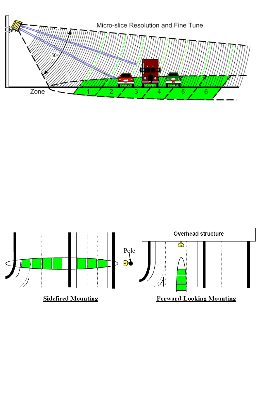
vehicles in multiple detection zones. When pointed onto a roadway, the RTMS microwave
beam projects an oval footprint. Its range is divided into multiple micro-slices, in which
vehicles are detected.
The RTMS receives reflected signals from all surfaces within its beam—pavement, barriers,
vehicles and trees. It maintains a background signal level for each micro-slice. Vehicles are
detected when their reflected signal exceeds the background level in their micro-slice by a
certain threshold. If that detection is part of a defined zone, its contact (optional) is closed
during the detection period to indicate detection. Statistical measurements are available
through two data points, including optional IP and Radio modems.
Chapter 1 About the G4 System
RTMS® G4™ User Manual © 2010 Image Sensing Systems, Inc. 1-6
Figure 1.1. RTMS Microwave and Beam Footprint
Several operating modes optimize internal parameter settings for highway and intersection
applications. Two mounting configurations are possible: side-fired and forward-looking.
In side-fired mounting:
The RTMS is located on a roadside pole and is aimed perpendicular to the traffic lanes.
Micro-slices corresponding to the location of traffic lanes are allocated as detection zones
during the setup process.
Each detection zone consists of multiple micro-slices.
The length of the detection zone is determined by the width of the beam's footprint.
In forward-looking mounting:
The RTMS is mounted on an overhead structure and is aimed along the center of the lane.
In highway applications the sensor's aiming angle is adjusted to confine the footprint to
one or two lanes.
The RTMS accurately measures vehicle speed and travel direction.
Figure 1.2. RTMS Mounting Configurations
Vehicle Detection
RTMS technology allows accuracy in the following conditions, even with a relatively low
mounting-height:
Severe weather.
Strong vibrations common to roadways that carry large vehicles.
When vehicles are completely occluded by other vehicles.
RTMS® G4™ User Manual © 2010 Image Sensing Systems, Inc. 2-1
Chapter 2
RTMS G4 Installation
Side-Fired Mounting and Aiming
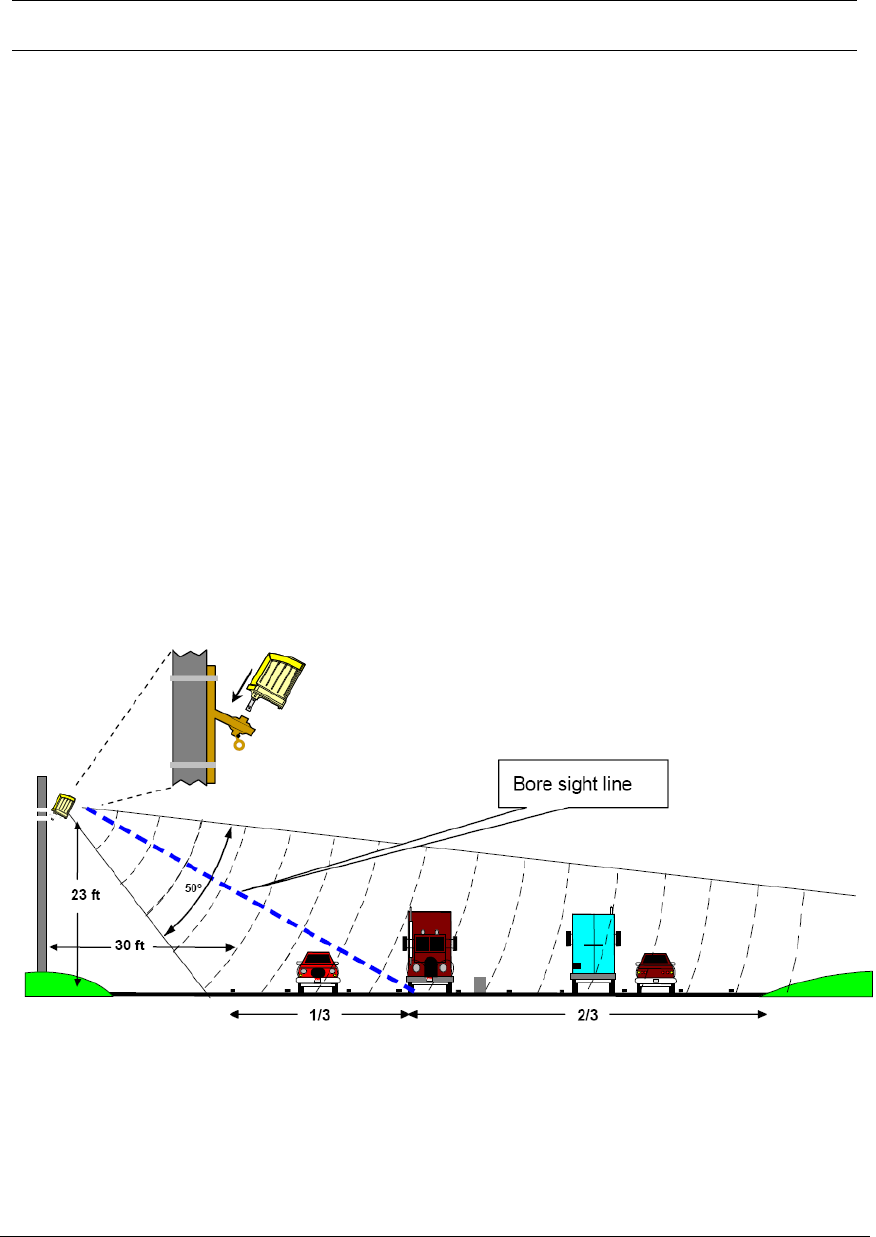
The distance between the close edge of the first lane of traffic to be monitored and the front of
the structure on which the RTMS is mounted is referred to as set-back. Set-back is a limiting
installation parameter of the RTMS. More lanes can be covered with a larger set-back.
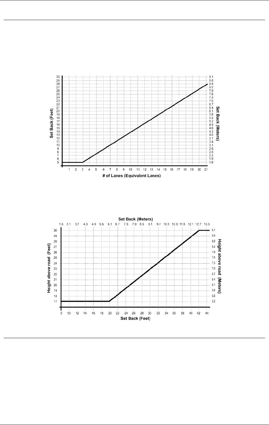
Use the diagrams in Figures 2.1, 2.2, and 2.3 to determine the setback required to monitor a
given number of lanes. The correct installation height can be determined once the set-back is
set. Height is measured relative to the road surface of the detection area. Do not measure
height from the bottom of the mounting pole.
Example: For 3 lanes the minimum set-back is 5 feet [1.5 m].
Note
It is almost always better to be 20 feet [6 m] further back from the
minimum than 2 inches [5 cm] closer than the minimum. If real estate is
available, move the RTMS further back.
The mounting height is based on the setback. Using the correct height value
allows the RTMS to be aimed so that it receives maximum return signal
while covering all required lanes. Mounting the RTMS at an incorrect
height will reduce accuracy.
Median strips are equivalent to lanes and must be included in total lane
count. For example: an eight lane road with a two lane-wide median strip
has 10 equivalent lanes.
Figure 2.1. RTMS Aiming

Chapter 2 RTMS G4 Installation
RTMS® G4™ User Manual © 2010 Image Sensing Systems, Inc. 2-2
Mounting and Aiming Procedure
Warning
Installation of ISS Canada hardware may require that you work above
the ground on a ladder or bucket truck. Please make sure you have all
the required equipment and are aware of potential safety issues before
starting any installation. DO NOT install any RTMS hardware if you
are unsure how to complete the installation or lack appropriate safety
equipment. ISS Canada does not recommend installing this hardware
during inclement weather.
The following equipment is required to mount and aim the RTMS unit:
Provided By ISS Canada. RTMS unit and its housing. Lynch pin.
Not Provided. Bolts or stainless steel banding. The bolt specifications depend on the
mounting requirements: for example, different bolts may be required when the RTMS unit
is mounted on a wooden pole than when the RTMS unit is mounted on a concrete wall.
7/16" wrench, 1/2" wrench, assorted tools to be determined by mounting specifications.
To mount and aim the RTMS unit:
1. Attach the bracket to the roadside pole (or another specified location) using bolts or
stainless steel banding.
2. Secure the RTMS to the mounting bracket by inserting the lynch pin.
3. Aim the RTMS as indicated on Figure 2-1. A 7/16" wrench is required to release/tighten
the ball-joint bolt.
4. Adjust the RTMS to be perpendicular to the travel lanes and level side to side.
5. Look from behind the unit and use the top sight-ridge as a guide to align the bore sight.
6. Tilt so that the top of the RTMS is aimed to the first 1/3 of the monitored lanes.
7. Secure the position by tightening the bolt.
Chapter 2 RTMS G4 Installation
RTMS® G4™ User Manual © 2010 Image Sensing Systems, Inc. 2-3
Set-Back Height Diagrams
Total width is the distance from the close edge of the first lane to the outside edge of the last
lane. Divide this number by the average lane width. For most applications, 12 feet is
considered a typical lane width. Example: total detection area = 120 feet; lane = 12 feet;
120/12 = 10 equivalent lanes. Minimum setback is 5 feet. Minimum height is 17 feet.
Figure 2.2. Set-Back Distance Chart
A setback greater than the minimum is desirable if room is available. Obtain the proper
mounting height based upon actual set-back distance.
Figure 2.3. Mounting Height Chart.
Zero Setback Options
The G4 hardware/software has new features that enable the RTMS sensor to work with zero
setback. For example: zero setback might be required for installation on a bridge. However,
appropriate setback distance should always be used when setback is available.
The zero setback feature has a Max range of ~50 feet, or 4 lanes of traffic.
Recommended mounting height is 14 feet.

Chapter 2 RTMS G4 Installation
RTMS® G4™ User Manual © 2010 Image Sensing Systems, Inc. 2-4
Cabling
Surge Suppression
Each RTMS unit has built-in surge-suppression hardware. Please keep in mind the following:
ISS Canada recommends installing external surge-suppression devices with every detector.
The communication and power lines of the RTMS should be equipped with external surge-
suppression devices when long cable runs are required.
Install surge-suppression devices close to the sensor. For example, in a cabling cabinet
mounted on the pole below the RTMS.
See Recommended Surge Protection for further details on installing surge-suppression devices.
The RTMS Cable
The RTMS ships with all required connectors, crimp pins, and back-shells.
RTMS G4 units (same as earlier RTMS models) use a single 32-pin MS connector for
power and communications.
The RTMS cable should be made from 20 or 22 gauge stranded wire arranged in twisted
pairs.
Cables exposed to outdoor conditions should be UV shielded.
The number of pairs required depends on the communication options chosen:
Table 2.1. Cable Pair Requirements
Communication Options
Number Of Pairs
Standard RS-232/485 plus power
3; 4 for RTS/CTS option or 485
Standard RS-232/485 and Internal RF modem option
plus power
4
RS-232/485 and TCP/IP plus power
5 for RS-232, 6 for RS-485
RS-232/485 and second serial port RS-232/422 plus
power
5, 7 if RTS/CTS Option used for both
ports
Zone contact option added to any of the above:
Option 1 one wire for each contact
(Max 16)
Option 2 two wires (1 pair) for each
contact (Max 8)
Preparing a Cable
Use cable such as the Belden number 95xx (xx indicates number of pairs. For example: 9516 is
a 6-pair cable). In preparing a cable note the following:
Decide whether or not to install extra cable pairs for growth purposes.
The crimp pins are designed for stranded wire only.
Do not use cable employing solid wires.
ISS suggests the Daniels Manufacturing Corporation crimping tool M22520/1-01 AF8
with head number M22520/1-02 or equivalent.
Do not solder crimp pins!
Chapter 2 RTMS G4 Installation
RTMS® G4™ User Manual © 2010 Image Sensing Systems, Inc. 2-5
Connecting a Cable to the RTMS
Use the following to create a cable to the RTMS device:
1. Thread cable through the backshell before inserting pins into shell.
2. Use the insertion tool (red) to insert wires with crimped pin into shell.
3. Use the extraction tool (white) to remove a crimped wire to correct an error.
4. Access to the serial connection should be available within view of the monitored lanes.
For example: inside an access panel or cabinet on the pole.
Verifying the sensor's calibration is easy when the user sees the RTMS data together
with manual counts.
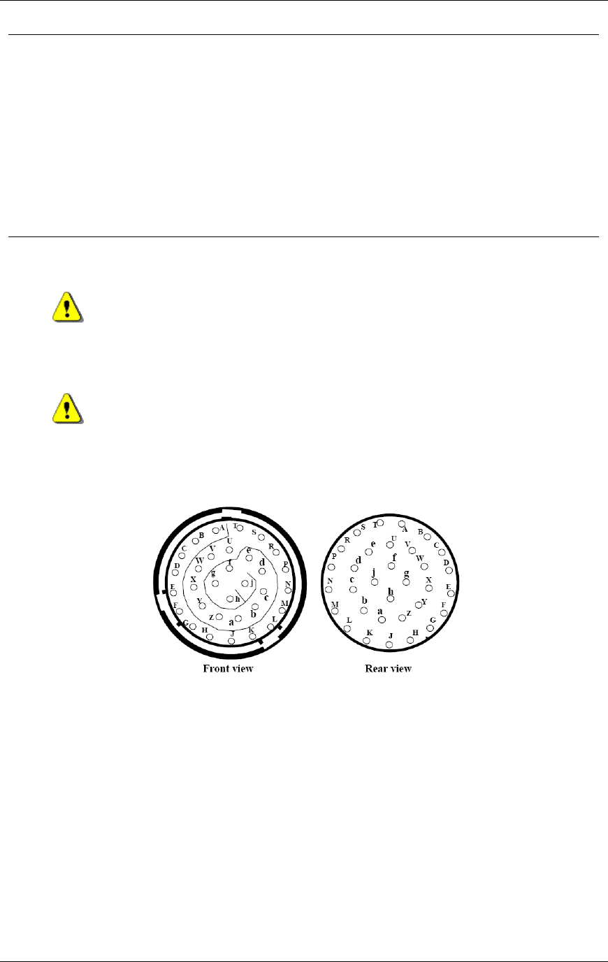
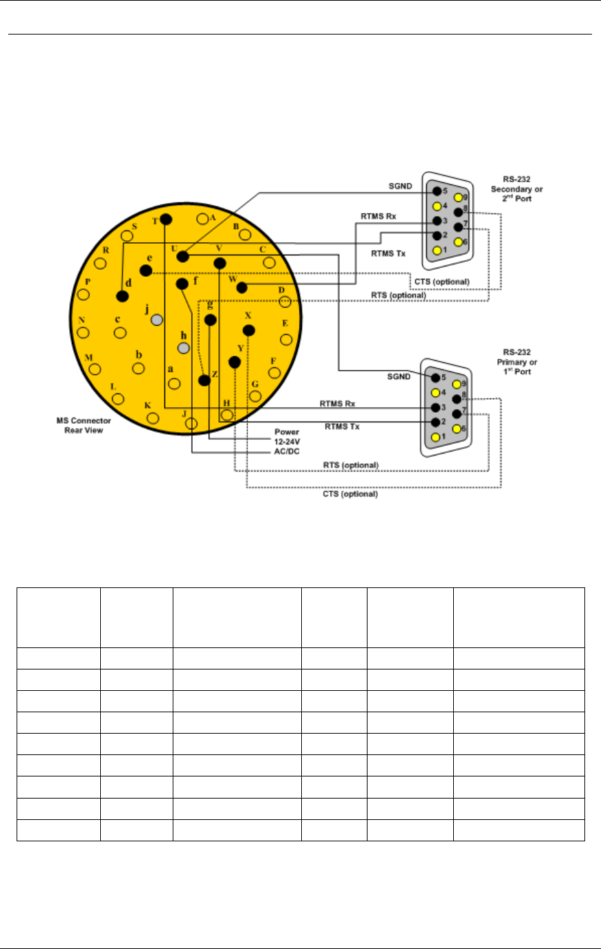
MS Connector Pin-Out
Caution
Pin labeling in Figure 2-4 is a guideline only – verify pin location on
actual connector before inserting wire.
Warning
The RTMS unit can be configured for a variety of communication
options. It is important to know which options are included with your
unit prior to preparing cables. MS connector pins cannot be shared.
Take note of the individual wiring instructions provided in this manual.
Figure 2.4. MS Connector

Chapter 2 RTMS G4 Installation
RTMS® G4™ User Manual © 2010 Image Sensing Systems, Inc. 2-6
Table 2.2. Cable Pair Requirements
Pin
Number
Function
Dual Loop Pin
Assignment
Dual Loop / Contact
Closure
A, B
Isolated Zone 1 or Zones 1, 2
A, J
Contact 1 Primary,
Contact 9 Secondary
C, D
Isolated Zone 2 or Zones 3, 4
B, K
Contact 2 Primary,
Contact 10 Secondary
E, F
Isolated Zone 3 or Zones 5, 6
C, L
Contact 3 Primary,
Contact 11 Secondary
G, H
Isolated Zone 4 or Zones 7, 8
D, M
Contact 4 Primary,
Contact 12 Secondary
J, K
Isolated Zone 5 or Zones 9, 10
E, N
Contact 5 Primary,
Contact 13 Secondary
L, M
Isolated Zone 6 or Zones 11, 12
F, P
Contact 6 Primary,
Contact 14 Secondary
N, P
Isolated Zone 7 or Zones 13, 14
G, R
Contact 7 Primary,
Contact 15 Secondary
R, S
Isolated Zone 8 or Zones 15, 16
H, S
Contact 8 Primary,
Contact 16 Secondary
W
Rx+ Ethernet or Rx 2nd port
Not Applicable
Not Applicable
T
Rx- (negative) Serial Port RTMS
input RS-232 Rx or RS-485 Rx-
(negative)
Not Applicable
Not Applicable
V
Tx- (negative) Serial Port RTMS
output RS-232 Tx or RS-485 Tx-
(negative)
Not Applicable
Not Applicable
U
Serial Ports and Contacts Signal
Ground
Not Applicable
Not Applicable
X
CTS or RS-485 Tx+
Not Applicable
Not Applicable
Y
RTS or RS-485 Rx+
Not Applicable
Not Applicable
Z
Rx- Ethernet or RTS 2nd Serial
port
Not Applicable
Not Applicable
a
Not used.
Not Applicable
Not Applicable
b
Not used.
Not Applicable
Not Applicable
c
Not used.
Not Applicable
Not Applicable
d
Tx- Ethernet Tx 2nd Serial port
Not Applicable
Not Applicable
e
Tx+ Ethernet or CTS 2nd Serial
port
Not Applicable
Not Applicable
f,g
Low Voltage power 12-24 VAC or
DC
Not Applicable
Not Applicable
h,j
115 VAC power
Not Applicable
Not Applicable
Chapter 2 RTMS G4 Installation
RTMS® G4™ User Manual © 2010 Image Sensing Systems, Inc. 2-7
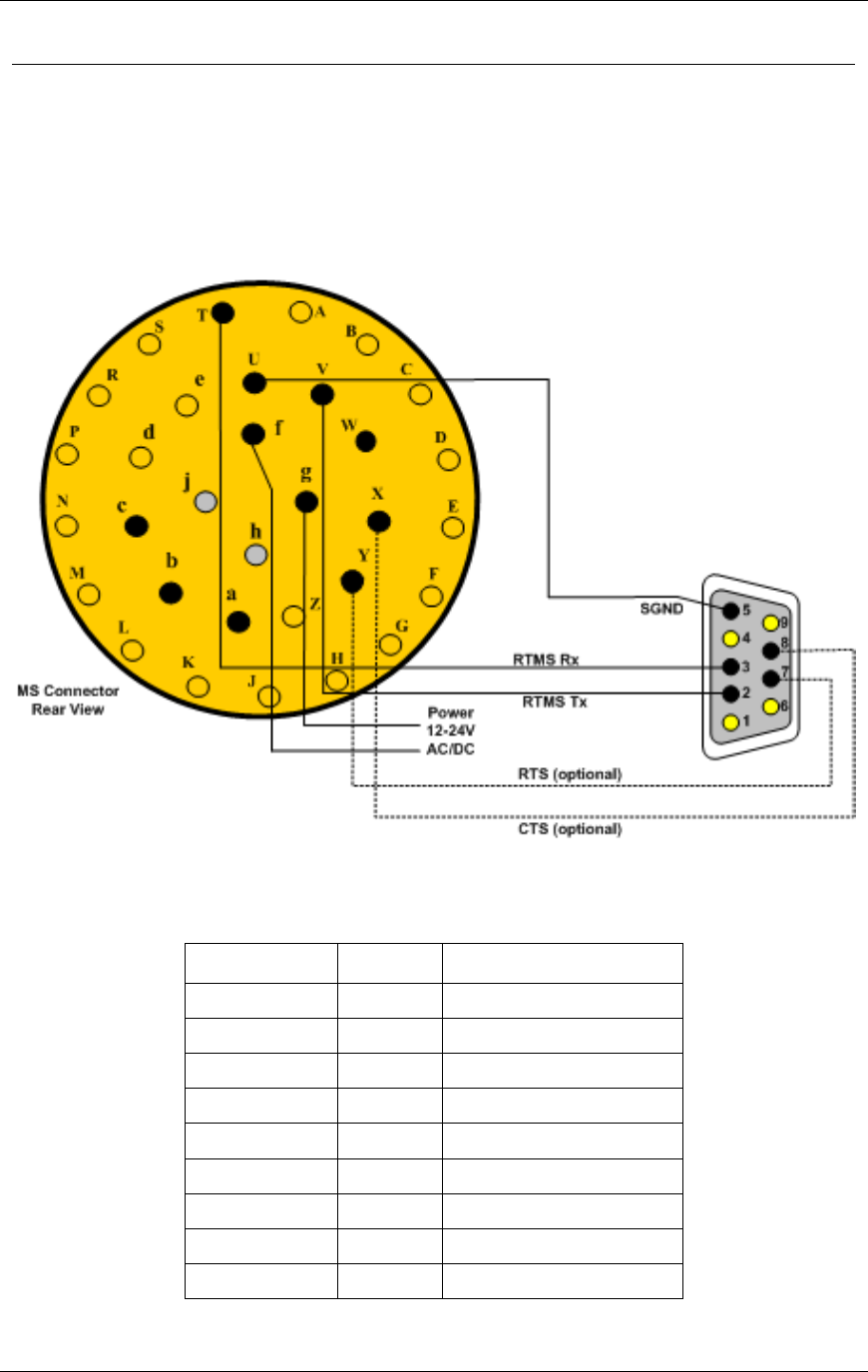
Standard RS-232 Port Wiring
The standard RTMS RS-232 port wiring consists of Transmit (Tx), Receive (Rx), RTS, CTS
and Ground lines wired to the MS pins respectively. The use of a female DB9 connector and
wiring shown allows the use of standard serial cable for direct connection to the PC for setup
purposes.
Rear views of connectors are shown to assist in cable preparation. The RTMS is configured as
a DCE device.
Figure 2.5. RS-232 Wiring Diagram
Table 2.3. G4 RS-232 Wiring Matrix (See Figure 2.5)
DB9 Pin
Signal
MS Connector Pin
1
NC
N/A
2
Tx
V
3
Rx
T
4
NC
N/A
5
SGnd
U
6
NC
N/A
7
RTS
Y
8
CTS
X
9
NC
N/A
Chapter 2 RTMS G4 Installation
RTMS® G4™ User Manual © 2010 Image Sensing Systems, Inc. 2-8
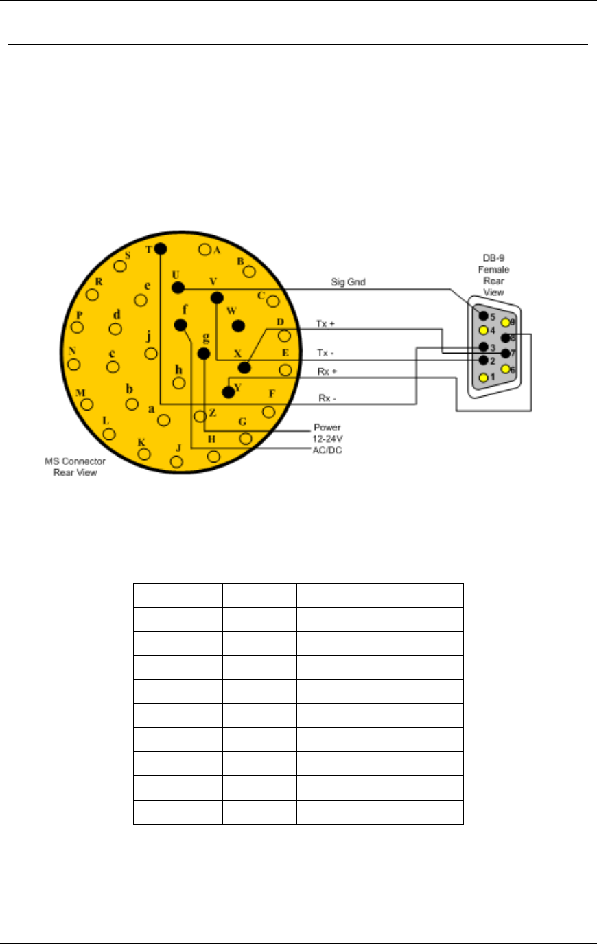
The RS-485 Port
Over short distances (30 ft [9 m]) the wiring diagram shown below is compatible with an RS-
232 port. There is no standard pin configuration for RS-485 on a DB9 connector. The wiring
diagram shown will connect directly to a RS-232 configured DB9 without the need for an RS-
232/RS-485 converter.
A disconnect point is recommended to allow the RTMS to be detached from the transmission
line without disruption of communications with other sensors on the line. See Connecting
RTMS to External Modems for details.
Figure 2.6. RS-485 Wiring Diagram
Table 2.4. G4 RS-485 Wiring Matrix (See Figure 2.6)
DB9 Pin
Signal
MS Connector Pin
1
NC
N/A
2
Tx-
V
3
Rx-
T
4
NC
N/A
5
SGnd
U
6
NC
N/A
7
Tx+
X
8
Rx+
Y
9
NC
N/A
Chapter 2 RTMS G4 Installation
RTMS® G4™ User Manual © 2010 Image Sensing Systems, Inc. 2-9
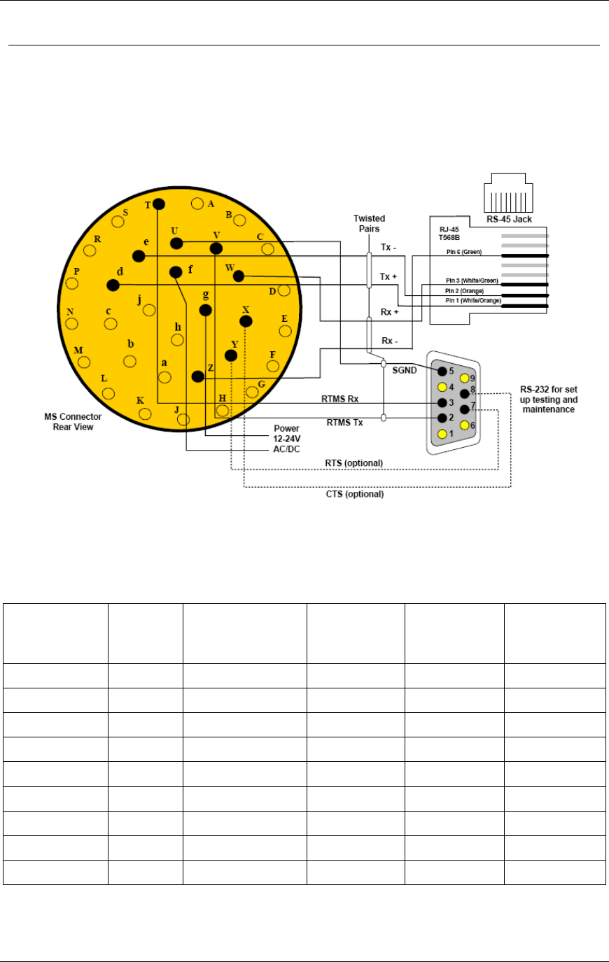
The TCP/IP Port with RS-232
CAT5 cable must be used for lengths between 30 ft (10 m) and 330 ft (100 m). Lengths greater
than 330 feet are not supported for Ethernet communication.
It is recommended that both TCP/IP and RS-232 ports be brought out to their respective
connectors, as shown. The RS-232 port is useful for setup and maintenance purposes, the IP
port for data collection and remote setup.
Figure 2.7. TCP/IP Port with RS-232 Wiring Diagram
Table 2.5. G4 RS-232 with TCP/IP Wiring Matrix (See Figure 2.7)
DB9 Pin
Signal
MS
Connector
Pin
RJ 45
Signal
MS
Connector
Pin
1
NC
N/A
1
Tx+
d
2
Tx
V
2
Tx-
e
3
Rx
T
3
Rx+
W
4
NC
N/A
4
NC
N/A
5
SGnd
U
5
NC
N/A
6
NC
N/A
6
Rx-
Z
7
RTS
Y
7
NC
N/A
8
CTS
X
8
NC
N/A
9
NC
N/A
Chapter 2 RTMS G4 Installation
RTMS® G4™ User Manual © 2010 Image Sensing Systems, Inc. 2-10
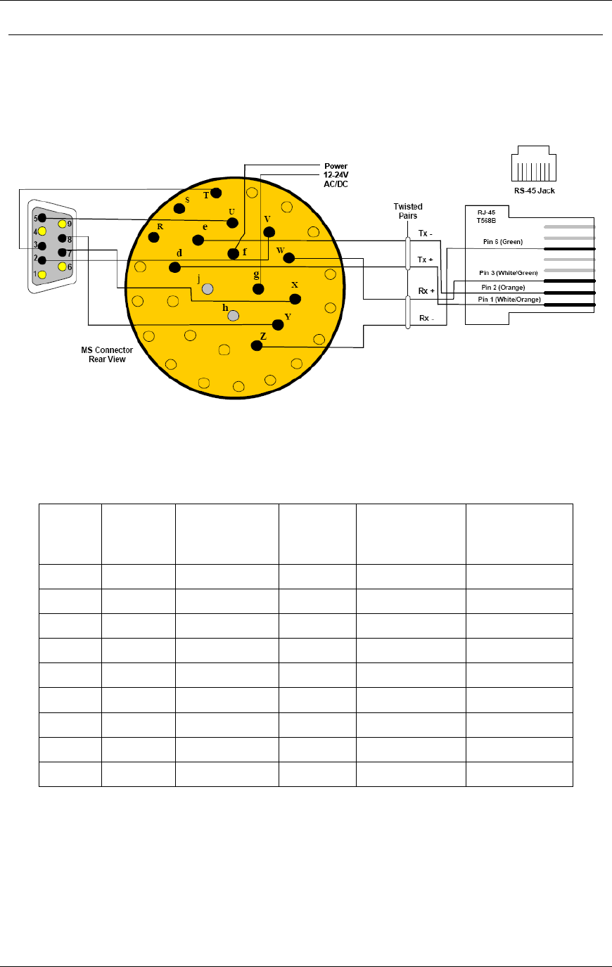
The TCP/IP Port with RS-485
It is recommended that both TCP/IP and RS-485 ports be brought out to their respective
connectors, as shown. The RS-485 port is useful for setup and maintenance purposes, the IP
port for data collection and remote setup.
Figure 2.8. TCP/IP Port with RS-485 Wiring Diagram
Table 2.6. G4 RS-485 with TCP/IP Wiring Matrix (See Figure 2.8)
DB9
Pin
Signal
MS
Connector
Pin
RJ-45
Signal
MS
Connector
Pin
1
NC
N/A
1
Tx+
d
2
Tx
V
2
Tx-
e
3
Rx
T
3
Rx+
W
4
NC
N/A
4
NC
N/A
5
SGnd
U
5
NC
N/A
6
NC
N/A
6
Rx-
Z
7
RTS
X
7
NC
N/A
8
CTS
Y
8
NC
N/A
9
NC
N/A
Chapter 2 RTMS G4 Installation
RTMS® G4™ User Manual © 2010 Image Sensing Systems, Inc. 2-11
Dual RS-232 Ports
The G4 has two independent serial ports (only available with additional hardware). The
primary port can be soft-configured to RS-485 operation for increased range. The secondary
port can be soft-configured to RS-422. The second port is also used when another device such
as an RF Modem or TCP/IP server is ordered with the unit. Below is the wiring for two
independent RS-232 ports configuration. Each port can be operated separately at its own speed
and carry different streams of information.
Figure 2.9. Dual RS-232 Wiring Diagram
Table 2.7. G4 Dual Serial Port Wiring Matrix (See Figure 2.9)
DB9
Pin
Port 1
Signal
MS Connector
Pin
Port
2
Signal
MS Connector
Pin
1
NC
N/A
1
NC
N/A
2
Tx
V
2
Tx
d
3
Rx
T
3
Rx
W
4
NC
N/A
4
NC
N/A
5
SGnd
U
5
SGnd
U
6
NC
N/A
6
NC
N/A
7
RTS
Y
7
RTS
Z
8
CTS
X
8
CTS
e
9
NC
N/A
9
NC
N/A

Chapter 2 RTMS G4 Installation
RTMS® G4™ User Manual © 2010 Image Sensing Systems, Inc. 2-12
Contact Closure
The G4 can provide, in parallel with the serial port and RF/IP/Cellular communications, up to
16 contact closures, delivering real time presence indication in each of its detection zones. The
contacts are arranged in two wiring configurations and operating modes:
8 Isolated contact pairs (as in RTMS Models X2/X3 and K3). In this configuration each of
the contacts is isolated from the other.
16 contact pairs. In this configuration all contacts will share a common Serial Ground. The
contact closures can be configured to operate either in Single Loop mode or Dual Loop
(Speed Trap) mode. Single mode provides up to 12 lanes or zones of detection, Dual mode
provides up to 8 lanes of Dual Loops.
You should wire the cable based on your preferred contact closure output mode and set the
RTMS mode using the Contact Closure Setup in the Advanced screen of WinRTMS.
Connecting RTMS to External Modems
The RTMS may be connected to a remote traffic data collection system over private telephone
lines using modems.
Multiple RTMS units connecting to remote systems, including the Cluster Hub or NEWS Hub
systems must be placed in Polled mode and may require the use of modems.
Modem Cables
A cable connecting the RTMS RS-232 port to the modem's RS-232 port must provide the
following:
Male connectors at both ends (null cable).
The cable must operate within the parameters provided below.
A modem's RS-232 ports will usually employ DB9 or DB25 connectors.
Table 2.8. Modem Cabling
Function
From RTMS
DB9
To Modem
DB9
To Modem
DB25
Transpose Tx and Rx
Pin 2, Pin 3
Pin 3, Pin 2
Pin 2, Pin 3
Connect ground
Pin 5
Pin 5
Pin 7
RTS to RTMS G4
Pin 7
Pin 8
Pin 5
Modem Side Control Looping
DCD to CTS
Pin 1 to Pin 7
Pin 4 to Pin 8
DSR to DTR
Pin 4 to Pin 6
Pin 6 to Pin 20
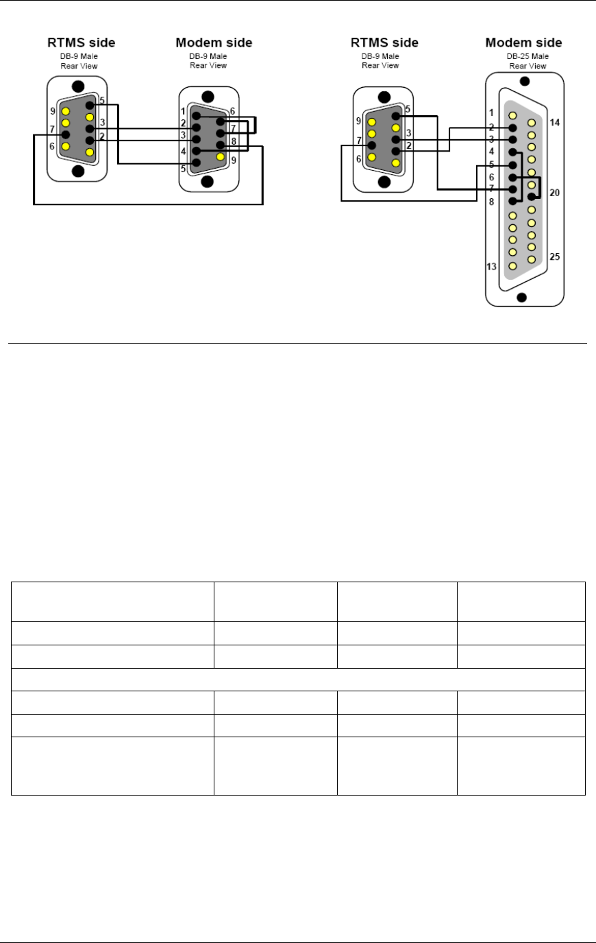
Chapter 2 RTMS G4 Installation
RTMS® G4™ User Manual © 2010 Image Sensing Systems, Inc. 2-13
Figure 2.10. RTMS G4-To-Modem Connections
Modem Sharing
Note
Downloading of the internal memory is not available with
this configuration.
RTMS units located in close proximity may connect to a single modem. A modem sharing
cable will have ―Y‖- construction and will consist of one DB-9M connector per RTMS, and
one DB-9M or DB-25M connector at the modem (as shown below).
Modem side strapping provides required flow control functions, not provided by the standard
RTMS RS-232 port.
Table 2.9. Modem Cabling
Connection/Function
From RTMS
DB9
To Modem
DB9
To Modem
DB25
Transpose Tx and Rx
Pin 2, Pin 3
Pin 3, Pin 2
Pin 2, Pin 3
Connect ground
Pin 5
Pin 5
Pin 7
Modem Side Strapping
Strap RTS to CTS
Pin 7 to Pin 8
Pin 4 to Pin 5
Strap DTR to DSR
Pin 4 to Pin 6
Pin 6 to Pin 20
Connect a 4.7 kΩ resistor
from Tx ground to prevent
noise.
Pin 3 to Pin 5
Pin 2 to Pin 7
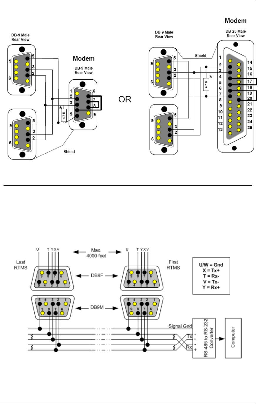
Chapter 2 RTMS G4 Installation
RTMS® G4™ User Manual © 2010 Image Sensing Systems, Inc. 2-14
Figure 2.11. Modem sharing "Y" cables. (No Memory Download.)
RS-485 Multi-Drop
The RS-485 setting of the G4 Serial Port allows up to 32 RTMS units to be employed on the
same serial bus over distances up to 4000 feet [1200 m].
The diagram Figure 2-12 shows the use of a 4-Wire line. The use of a half-duplex 2-Wire line
is feasible but it is suitable for data collection only. Consult RS-485/422 Application Guides
for details on wiring solutions for your project.
Figure 2.12. RS-485 Multi-Drop Wiring

Chapter 2 RTMS G4 Installation
RTMS® G4™ User Manual © 2010 Image Sensing Systems, Inc. 2-15
Wiring Notes
1. The DB9 connectors and terminal blocks serve as a disconnect point, which allows
disconnecting the RTMS from the transmission line for direct connection to the laptop's
COM port for setup.
2. Terminating resistors (100-120 ohms) are required at the extreme ends of the Receive and
Transmit transmission pairs.
3. Transmit and receive pairs must be transposed when connecting to a DTE (PC, Data
processing System). To interface with a PC an RS-485/232 converter may be required as
PCs typically do not have RS-485 interfaces.
4. RS-485/232 converter connector type and pin assignment are not shown as these are not
standardized and vary between models.
RTMS Troubleshooting Guide
Field troubleshooting of the RTMS consists mainly of ensuring that the unit is powered and
communicating. Communication with the sensor in Normal mode is confirmed by presence of
the moving vehicles and menu buttons, and by the flashing of the indicator in the lower right
corner of the screen, denoting data transmission activity. The table below outlines symptoms
and suggested action in troubleshooting power and communication problems. Further
information on problems with the power supplied to the unit, with the wiring, or with the
communications parameters not being set correctly is provided below the table:
Symptoms
Possible Causes
Suggested Action
Timeout has expired and the
main Communication Screen is
displayed.
RTMS is not powered.
Check that the supply voltage is within
limits at source and at the MS connector.
Voltage outside the limits (too low or too
high) will cause power supply to shut
down.
Cable problem.
Check cable pin-out and continuity.
PC and sensor are
communicating (Sensor settings
are displayed on buttons) but
target ―blips ―are not shown on
the main screen.
RTMS is not in
Normal mode.
Unit is improperly
aimed.
Internal parameters
corrupted.
MW module fault.
Ensure the unit is in the Normal mode.
Check sensitivity setting. See if targets
appear when sensitivity is increased.
Cycle power to unit and then edit
parameters (mode, sensitivity, zone setup,
etc).
Run Self-Test if above not successful.
Report findings to ISS Canada.
Main screen shows target blips
but no zone icons or parameters
on buttons.
RTMS transmits and
WinRTMS displays
received data but
RTMS has not
received the
WinRTMS READ
command.
Check cable to ensure continuity between
MS connector pin T and COM port's pin
3.
Notes on Power:
The RTMS G4 is a constant power device that requires in its basic configuration 3 watts of
power. Electrical power has two components, voltage and current; both must be available in

Chapter 2 RTMS G4 Installation
RTMS® G4™ User Manual © 2010 Image Sensing Systems, Inc. 2-16
the correct ranges to operate the G4.
The voltage must be between 12 and 24 volts (DC or AC RMS) with the voltage level read at
the RTMS. Voltages below 12 volts will be insufficient to turn on the G4; voltages above 24
volts will cause the G4 to shut down to protect itself from an overvoltage condition. Losses in
the cable must be addressed in setting the voltage to be supplied to the unit.
Current in sufficient quantity must be available: at 12 volts, the G4 will draw 250 mA of
current; at 24 volts 125 mA (base model, higher for units with additional communications
options).
Using an adaptor that provides 12 volts and 100 mA of current means that the total power to
the RTMS will be 12*0.1 = 1.2 watts, or roughly 40% of the power needed to turn the G4 on.
On power up, there will be an inrush current that will be several times higher than the
operating current. The power supply must be able to handle this temporary current flow.
If the power supply is unregulated (such as a simple step-down supply from 120 VAC to 24
volts (AC or DC)), the output voltage may be higher than specified when the current draw is
less than maximum available from the supply This may cause the G4 to sense an overvoltage
condition and shut down to protect itself.
If additional hardware is added to the G4, such as a radio modem or an Ethernet card, the
power required to operate the G4 will increase. The voltage seen by the G4 will remain the
same, but the current will increase to meet the new power requirement.
Note on Cabling:
ISS Canada recommends that the design of an RTMS installation include a breakout box close
to the RTMS that can be used for setup and maintenance purposes, and can include surge
suppression circuitry and external communications devices as required. Reference designs are
available.
Notes on Communications:
The base communication method used with the G4 is serial RS-232 or RS-485. Port 1 is the
main port that is connected to the outside world, Port 2 (optional) is installed to speak with
other internal devices such as a DSS or Cellular radio, or a serial-to-Ethernet converter. Port 2
can also be connected to the MS connector for direct access to the outside world (factory
option).
It is recommended that serial port 1 be accessible to the outside world for maintenance
purposes, even if the primary communication with the G4 will use another method.
Communication between the second serial port and another device will be fixed at a rate of
115200 bps. When connecting to an internal device through the serial ports, it is necessary that
serial port 1 is set to 115200 bps for the connection to be successful.
Both serial ports can support hardware handshaking if the external lines are available. It is
critical that hardware handshaking (RTC/CTS) not be enabled using the WinRTMS software if
the lines are not installed in the cabling. Enabling RTS/CTS without these lines will prevent
the RTMS from communicating with the outside world.

Chapter 2 RTMS G4 Installation
RTMS® G4™ User Manual © 2010 Image Sensing Systems, Inc. 2-17
RTMS Technical Specifications
Microwave Signal and Coverage Area
Model K4
Center Frequency
24.125 GHz
Bandwidth
50 MHz
Power Output
100 mW
Beam Width—Vertical (Elevation)
50°
Beam Width—Horizontal (Azimuth)
12°
Side Lobes
>-20 dB
Range
6-250 feet [2-75 Meters]
Number Of Detection Zones And Lanes
12
Accuracy of Measurement & Error Rates
Measurement
% Error *
Per Lane Volume—Side-Fired
5%
Volume Range
0-65535
Per Lane Occupancy—Side-Fired
5%
Occupancy Range & Resolution
0-100%, 0.1%
Per Lane Classification By Length (6 classes)
10%
Class Lengths Limits range and resolution
83.6 ft [25.5 m 0.1 m]
Average Per Vehicle Speed—Side-Fired
10%
Speed range and resolution
100 MPH, 1 MPH [0-160 km/h, 1 km/h]
Resolution of time events
1.25mS
Voltage readout resolution
0.1v
*Accuracy Performance Conditions
Error performance parameters outlined above are achieved under normal, high-flow traffic
conditions and are subject to proper installation and setup. Lower accuracy is expected under
the following conditions:
Low speed, high congestion conditions: The RTMS tends to be less accurate under very
low speed conditions (below 1 mph [1.6 km/h]).
Improper selection of installation site: insufficient set-back, height beyond the
recommendation, obstruction by barriers or high fences before monitored lanes.
Improper fine tune setting for the road geometry (lane width, barriers, etc.) will result in
―splashing‖ and, therefore, over-counting.
In Forward-Looking Hwy configuration the following conditions may result in errors:
High variance between the volumes in the speed trap zone.
Improper aiming, mounting height (too high) or incorrect offset parameters
Obstructions within the trap range.

Chapter 2 RTMS G4 Installation
RTMS® G4™ User Manual © 2010 Image Sensing Systems, Inc. 2-18
Mechanical
Measurement
Dimensions
Enclosure Dimensions
8×8×6 inches [21×21×16 cm ]
Weight (Without Optional
Equipment)
3.5 pounds [1.5kg]
Enclosure Material
polycarbonate
Weatherproofing
NEMA-4X and IP-65
Mounting
Zinc plated steel universal ball-joint bracket capable of
support a load of up to 20 lbs [8.33 kg]. (Vertical or
horizontal). Lynch-pin locking allows quick sensor
replacement without disturbing the aiming.
Allowable pole flexing
Less than 5 degrees
Power Requirements & Consumption
Component
Details
RTMS standard power
requirement
12-24 VAC or DC
Polarity protection
not polarity sensitive
Over-voltage shutdown limit
34 VDC or 24 VAC
Recommended fusing
(external)
2 A slow blow minimum
Power consumption (Without
optional equipment)
3 Watts
Automatic recovery from
power failure
Within 20 seconds
Commercial AC power option
115±20 VAC @ 50-60 Hz
Interfaces
Isolated Serial ports programmable to RS-232/485 including hardware handshake. (Second
serial port is only available with additional hardware.) Speed is adjustable between 2400
and 115200 bits-per-second. RS-485 range: up to 4000 feet [1200 m].
Optional Bluetooth wireless connection
Optional Second Serial port programmable to RS-232/422 including hardware handshake
Optional integral 10/100 Base-T Ethernet supporting TCP, UDP, IP, ARP, ICMP
Optional IP Camera with multiple modes of operation (See separate specification.)
Optional Contact pairs: 8 isolated contacts or 16 common ground contacts rated at
Maximum current 100 mA; Maximum voltage 350 V; Maximum dissipated power 300
mW.
Internal Data memory capacity: 8 Mb (90 days with all reporting options on and a 5-
minute message period, 6 months for typical configuration.)
Upgrade Capability

Chapter 2 RTMS G4 Installation
RTMS® G4™ User Manual © 2010 Image Sensing Systems, Inc. 2-19
User upgrades of both hardware and firmware available. RTMS supports remote firmware
upgrade.
Surge Immunity
The RTMS withstands ±1kV surge (rise time = 1.2 µsec, hold = 50µsec) applied in differential
mode to all lines, power and output, as defined by IEC 1000-4-5 and EN 61000-4-5 standards.
Environmental Conditions
Operating Limits
Shipping & Storage
Temperature Range
-35 to 165°F [-37 to +74°C ]
-40° to 171°F [-40°
to 80°C]
Humidity
Up to 95% Relative Humidity
Up to 95% Relative
Humidity
Vibration
2 g up to 200 Hz
Shock
5 g 10 ms sine wave
Wind
Winds up to 100 mph [160 km/h] will not
degrade performance
Precipitation
Up to 100 mm/h
Printed circuit boards are conformally coated for protection against humidity and corrosion.
Except as may be other stated herein for a particular item, no item, component, or subassembly
shall emit a noise level exceeding the peak level of 55 dBa when measured at a distance of one
meter away from its surface.
Electromagnetic Interference
Certified under US FCC Rule part 15 Class A; Canadian CSA C108.8 M1983 Class A; CE.
Reliability
The RTMS is designed for Mean Time Between Failures (MTBF) in its operating environment
of 90000 hours [10 years].
Chapter 2 RTMS G4 Installation
RTMS® G4™ User Manual © 2010 Image Sensing Systems, Inc. 2-20
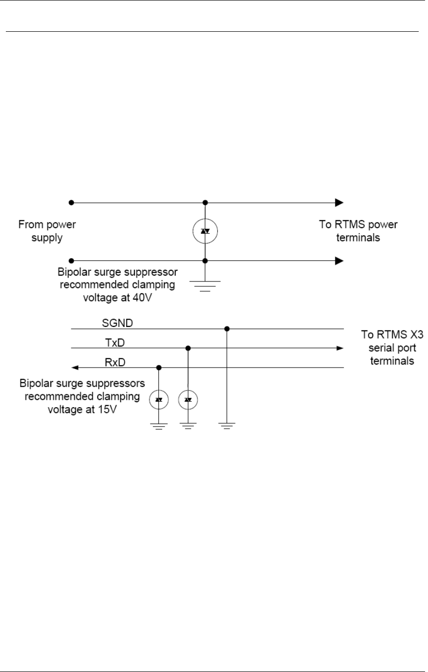
Recommended Surge Protection
It is recommended that communication and power lines of the RTMS be equipped with surge
protecting devices, located as close as possible to the sensor. For example: locate surge
protection in a cabling cabinet mounted on the same pole as the RTMS. The surge suppression
should be applied as follows:
The Tx and Rx communication lines should employ low capacitance, bipolar surge
suppressors with a clamping voltage of 15 V.
The Signal ground line should be grounded.
A bipolar surge suppressor with a clamping voltage of 40 V shall be placed between two
low voltage (16-18V AC or 12-24VDC) power lines.
One of the power lines, negative line in case of DC, shall be grounded.
Figure 2.13. RTMS Surge Suppression

RTMS® G4™ User Manual © 2010 Image Sensing Systems, Inc. 3-1
Chapter 3
G4 Software
Reference
RTMS System Requirements
Once installed, RTMS sensors must be calibrated using the RTMS Setup Utility software.
System requirements are as follows:
Component
Requirements
Operating
System
Windows XP, Windows Vista
Software
Microsoft .NET Framework 3.5
Hardware
USB (with a USB-to-serial adapter), serial, or Ethernet port to
communicate with RTMS hardware
About The RTMS Setup Utility
WinRTMS is supplied as a self-installing program named WinRTMSxxxinstall.msi.
Will install C:\Program Files\EIS\WinRTMS.
This folder contains the WinRTMS4.exe executable program and auxiliary files.
The installer places a shortcut on the desktop.
Communication
The WinRTMS program can communicate:
With a single RTMS (Direct)
With multiple RTMS sensors (when these sensors are on the same communications
channel and Polled Data Mode is active (Multidrop).
Procedures
The procedures listed below show you how to perform all common setup and software
procedures.

Chapter 3 G4 Software
RTMS® G4™ User Manual © 2010 Image Sensing Systems, Inc. 3-2
Microsoft .NET Runtime Warnings
WinRTMS runs with Microsoft .NET 2.0 and higher. Run the software with Microsoft .NET
3.5.1 for optimal performance. In most cases the software performs acceptably but you may
notice visual differences in the graphical user interface. The software provides a warning if the
.NET version is incompatible.
Figure 3.1. The .NET Version Warning. Click Ignore to proceed.
Chapter 3 G4 Software
RTMS® G4™ User Manual © 2010 Image Sensing Systems, Inc. 3-3
How to Navigate the RTMS Interface
The WinRTMS buttons and menus may be operated by any method listed below. The terms
select and click are used throughout this manual to describe actions you can complete using the
mouse or keyboard:
Figure 3.2. The RTMS User Interface.
The interface consists of buttons and text displays.
Point and click to select a button.
Navigate using up/down/left/right keys and ENTER keys. Select by the arrow keys and
take action by hitting ENTER.
In some cases the TAB key can be used to navigate between the two main panels.

Chapter 3 G4 Software
RTMS® G4™ User Manual © 2010 Image Sensing Systems, Inc. 3-4
Get Started
Caution
Windows may disable the COM port if port activity is detected during
the boot process. DO NOT connect the RTMS to the COM port before
Windows startup is complete.
When the hardware installation is complete, getting started with the RTMS software is a three-
part process:
1. Establish Physical Connection: power up computer and connect computer to RTMS
hardware via appropriate cable.
2. Establish Data Connection: establish an active data connection with the RTMS hardware.
3. Establish Traffic Detection: configure traffic detection parameters and begin detection.
While configuring your system, use the three-part list shown above to create your own task list
and gauge your progress.
Establish a Connection with the RTMS Hardware
Once the hardware is installed, you must establish a data connection between the RTMS
hardware and a computer running the RTMS software. To establish a connection between the
RTMS hardware and software:
1. Connect the RTMS hardware to an already-running personal computer.
2. With the RTMS sensor powered and connected to the PC, click the WinRTMS4.exe icon
to launch the RTMS Setup Utility program.
While trying to establish communications, WinRTMS looks for a single sensor that
matches the current settings (address, communication rate).
If successful in establishing communications, WinRTMS displays setup options on the
Main Screen.
If unsuccessful, WinRTMS performs a scan for various baud rates to find the correct
one. This might take a few minutes.
3. If unable to establish communications, WinRTMS opens the Communications Screen to
allow you to direct a search for the RTMS. Possible causes are:
See the Troubleshooting Guide for additional suggestions.
Microsoft .NET Framework 3.5 is not installed.
RTMS is not powered.
RTMS is not connected to the PC.
RTMS connection cable is faulty.
Wrong COM port is selected.
Communication to RTMS is IP.
Tx & Rx lines are crossed.
COM port is being used by another program.
Chapter 3 G4 Software
RTMS® G4™ User Manual © 2010 Image Sensing Systems, Inc. 3-5
How to Run WinRTMS in Demo Mode
If you are a new user, use the following instructions to start and configure the RTMS:
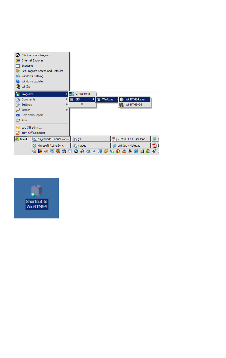
1. Select Start » Programs » ISS Canada » WinRTMS » WinRTMS4.exe.
2. Alternatively, you may start the software from the desktop if you chose to install a desktop
shortcut during the installation process.
3. Double click the shortcut icon.
Chapter 3 G4 Software
RTMS® G4™ User Manual © 2010 Image Sensing Systems, Inc. 3-6
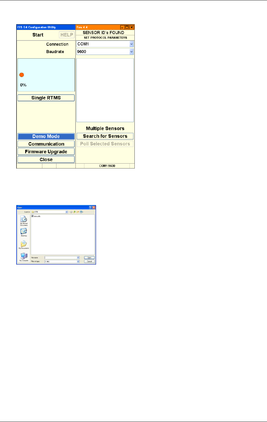
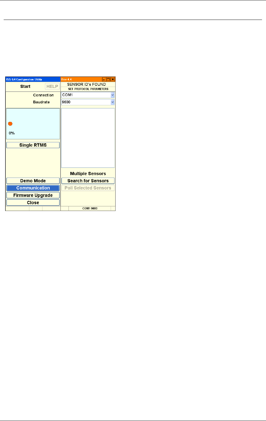
The software starts and displays the start screen.
4. Left click the button named Demo Mode. This button is found at the bottom left of the
user interface.
This displays the Open file dialog.
5. Double click the sample file named DEMO.DTB or any other saved G4 setup file.
Chapter 3 G4 Software
RTMS® G4™ User Manual © 2010 Image Sensing Systems, Inc. 3-7
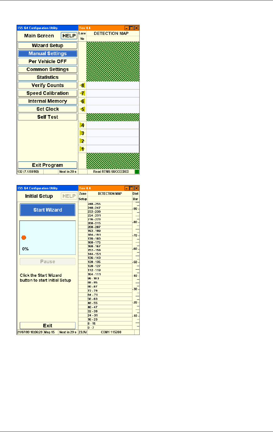
This initializes the program with sample data.
6. Left click the button named Wizard Setup. This displays the wizard setup screen:
7. Left click the button named Start Wizard.
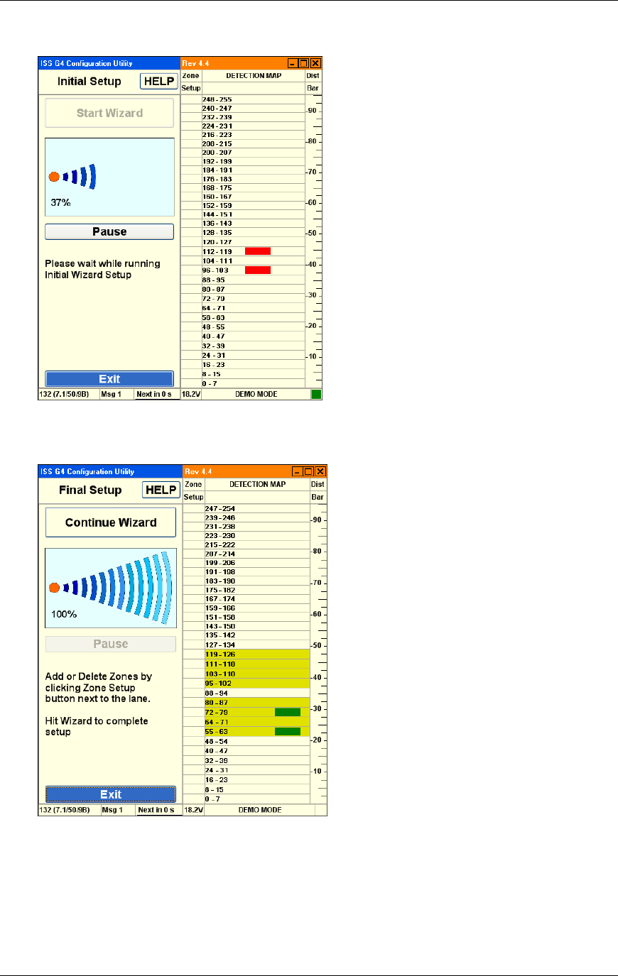
Chapter 3 G4 Software
RTMS® G4™ User Manual © 2010 Image Sensing Systems, Inc. 3-8
The wizard starts and displays progress
8. When complete, the wizard displays lane and traffic information. Configure these options
as appropriate:
9. Left click the button named Continue Wizard to complete the setup process:
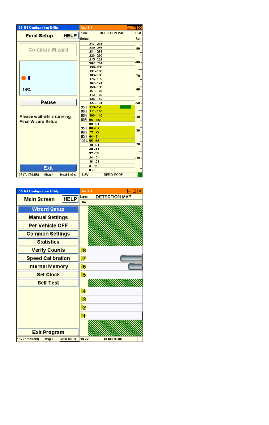
Chapter 3 G4 Software
RTMS® G4™ User Manual © 2010 Image Sensing Systems, Inc. 3-9
The software displays progress.
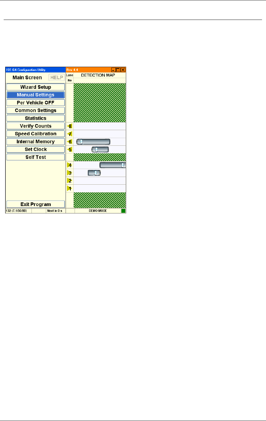
The RTMS Main Screen is displayed when complete:
10. Configure the remaining options as needed.
Chapter 3 G4 Software
RTMS® G4™ User Manual © 2010 Image Sensing Systems, Inc. 3-10
How to Modify or Troubleshoot the Connection with the RTMS
Hardware
The Communications Screen allows you to troubleshoot data connections if you encounter a
problem making a data connection on startup. You can also use these options to reconfigure
communication parameters as needed throughout the product life-cycle.
The basic communication options screen:
1. Use the basic communication screen to accomplish the following:
Change the WinRTMS Utility communication parameters such as the mode from
Single RTMS (Direct) to Multiple Sensors (Multidrop).
Search for Sensors by first using the default port (and parameters) before making any
changes. During the search for Multiple Sensors, several sensors may be found. In this
case their Sensor ID numbers will be displayed, allowing polling of all of them or a
Selected Range of IDs as well as focusing on a single sensor ID.
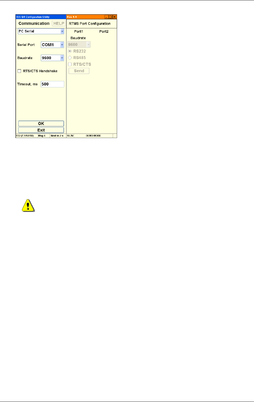
8. Click the Communication button to display advanced communication parameters in both
panels:
Chapter 3 G4 Software
RTMS® G4™ User Manual © 2010 Image Sensing Systems, Inc. 3-11
9. Use the advanced communication options on the left side of this screen to accomplish the
following:
Set the WinRTMS PC COM port and baud rate for communicating with the RTMS
when Serial is selected.
The TCP/IP selection allows you to set the IP address WinRTMS uses to communicate
via IP-based connections.
Warning
Activating RTS/CTS without wiring in place to the RTMS leads to
loss of communication.
10. Use the advanced communication options on the right side of this screen to accomplish the
following:
Set RTMS Sensor communication parameters of both ports to the correct speed from
the drop menu.
Activate RTS/CTS handshake when necessary.
Alter communication speed (baud rate).
9600 bits per second (bps) is the factory default for serial units.
Data rates below 9600 are useful where high quality transmission lines are not
available. They are however, unsuitable for setup and must be selected after
setup has been completed. When using data rates below 9600 bps, the RTMS
data mode must be set to STAT to reduce the amount of data and prevent
communication problems. See DATA MODE for further details.
11. Click Send to change the RTMS and WinRTMS will change automatically.
12. Click OK to finish.
Chapter 3 G4 Software
RTMS® G4™ User Manual © 2010 Image Sensing Systems, Inc. 3-12
How to Set Up Serial Communication
Serial communication is the simplest form of communication between an RTMS sensor and
WinRTMS. To configure serial communication:
1. Power up the computer.
2. Connect the RTMS sensor to the computer with a serial cable.
3. Start WinRTMS.
4. The WinRTMS software starts and begins to search for sensors. The software splash
screen is displayed. This process may take a few minutes.
The software displays the search screen if a sensor is not found:
This screen allows you to direct a search for sensors.
The software displays basic configuration if a sensor is found:
This screen allows you to configure the RTMS.
Chapter 3 G4 Software
RTMS® G4™ User Manual © 2010 Image Sensing Systems, Inc. 3-13
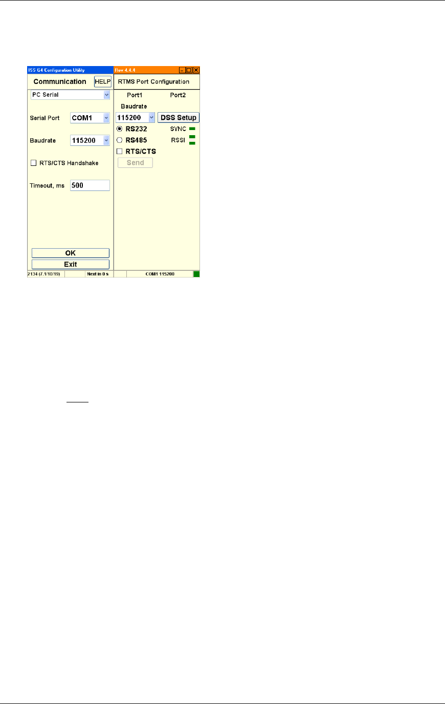
How to Set Up DSS
To configure WinRTMS to communicate with a sensor via digital radio modem:
1. Start WinRTMS and connect to the RTMS sensor.
2. Select Manual Settings from the listed options.
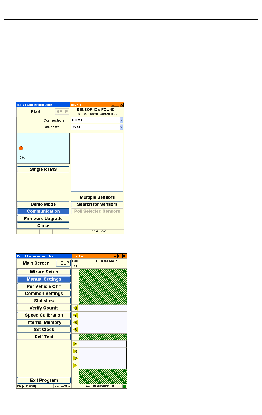
3. Select Communication from the listed options. The RTMS Port 1 Baudrate must be set
to 115200 before accessing the internal DSS radio modem:
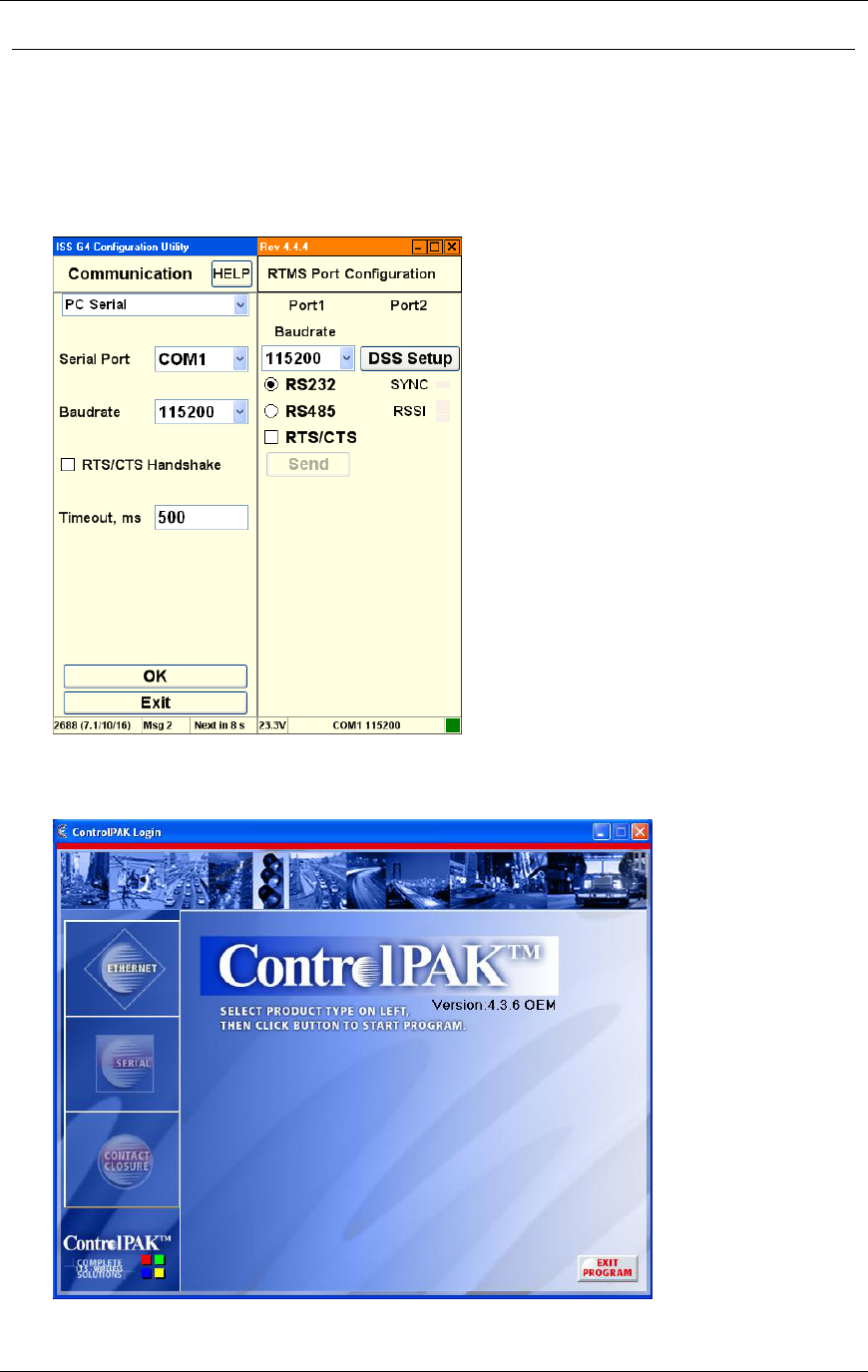
4. Left click the button named DSS Setup. This will automatically open a window so that
Encom’s Controlpak utility can be located and run. (Encom’s ControlPak software must be
run on the same computer. Select SERIAL and 520 Series:
5. Ensure the connection settings are set to 115200, 8 data bits, no parity and 1 stop bit. The
Chapter 3 G4 Software
RTMS® G4™ User Manual © 2010 Image Sensing Systems, Inc. 3-14
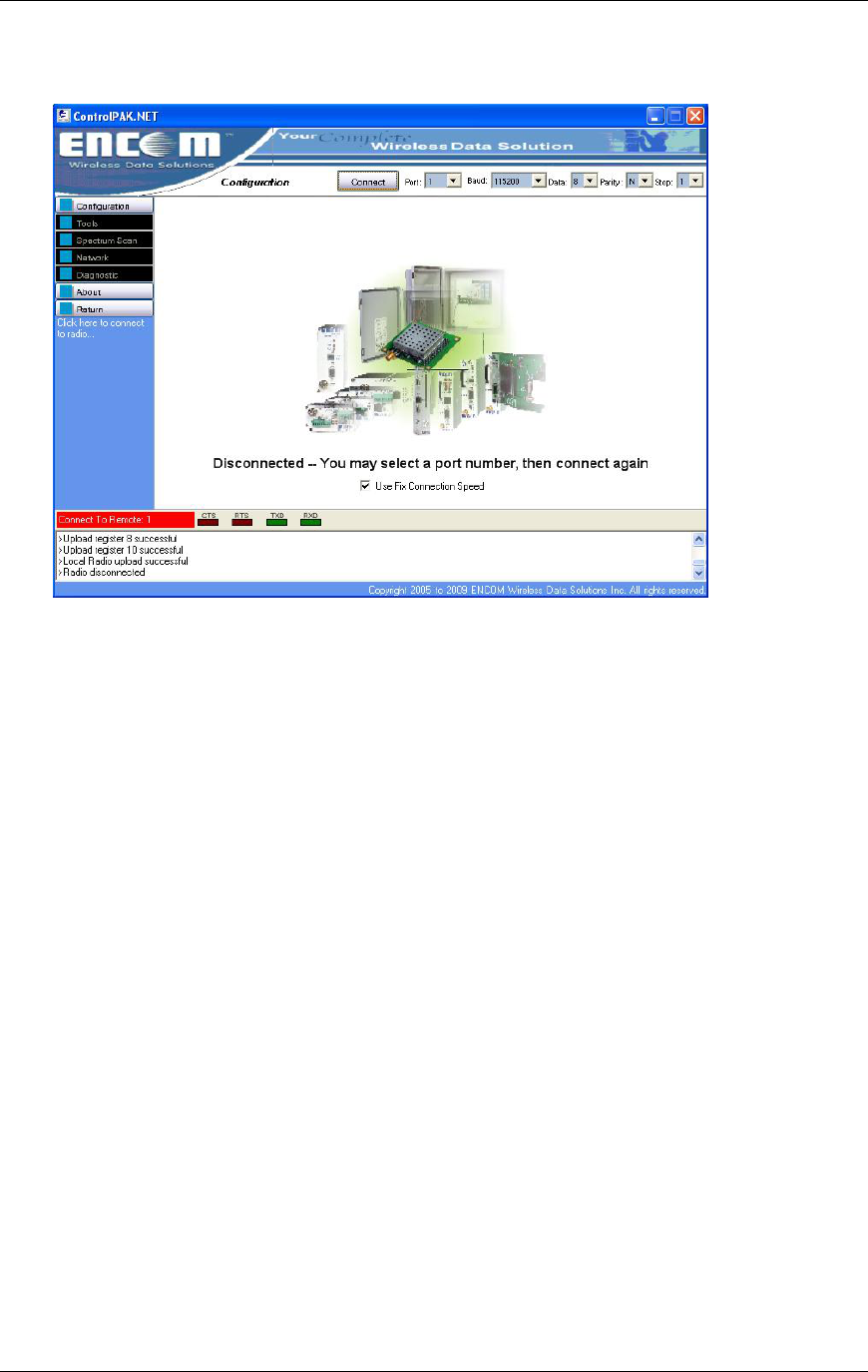
COM port may vary if you are using a USB-to-serial converter. Use Fix Connection
Speed should already be checked. To access radio settings, click Connect:
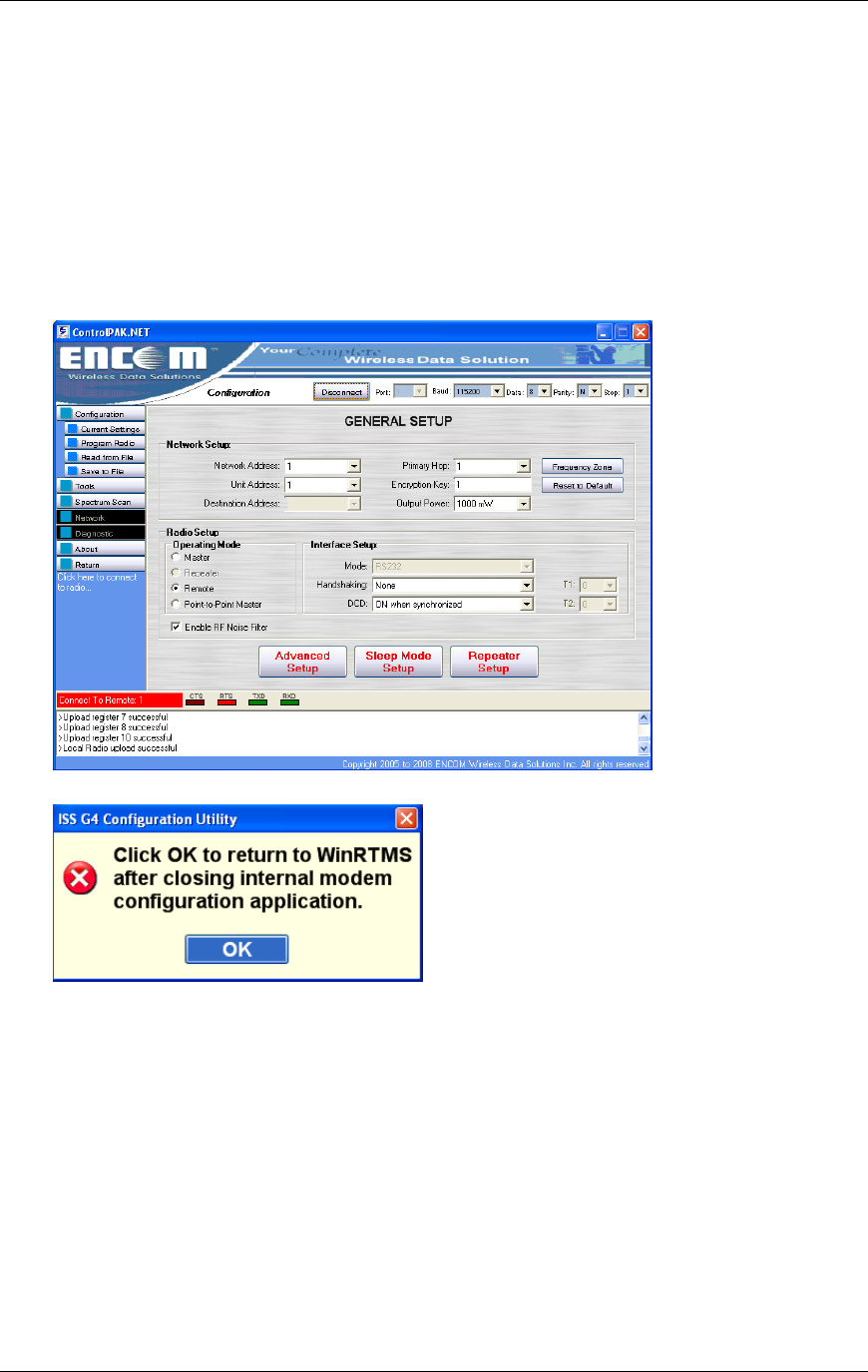
6. Enter Network Setup values: Network Address, Unit Address (unit address must match
G4 sensor ID), Primary Hop, Encryption, and Output Power.
7. To load radio settings, click Program Radio.
8. Verify the bottom window shows Local Radio upload successful.
9. To close Controlpak utility, click Return, and then Exit program.
Chapter 3 G4 Software
RTMS® G4™ User Manual © 2010 Image Sensing Systems, Inc. 3-15
10. Left click File, and select a text file containing a properly formatted modem instruction
set:
Note
Network setup limits for 520 series radio:
Network address. Range is 0-99.
Unit address. Range is 1-254.
Primary hopping pattern. Range is 0-61.
Encryption key. Range is 0-65535.
Power setting range is 1, 10, 100 and 1000 mW.
11. To return to WinRTMS, click OK:
12. From the Manual Settings dialog, select Data Mode.
Chapter 3 G4 Software
RTMS® G4™ User Manual © 2010 Image Sensing Systems, Inc. 3-16
Proper communication is indicated by the green synchronization indicator below the DSS
Setup button. The RSSI (Received Signal Strength Indicator) reflects the RSSI status: 1, 2,
or 3 bars. Three bars indicate the strongest received signal:
The master DSS communicating with the RTMS slave or repeater must be of the same
type and frequency band. All units supplied on the same order will be of the same type
and frequency. Refer to the manufacturer's documentation and instructions for setup of
the master DSS parameters.
Output Power Level is determined based upon the Radio Site Survey. Strength of
signal is important to ensure data quality. If the power setting is too high, it may
interfere with other radio systems in the area. If it is too low, the data messages may be
missed.
You must set the Unit Address=RTMS Sensor ID.
The Spider Controller only accepts 8 lanes per sensor. Therefore only 8 lanes can be
configured when G4 is operating in Spider mode.
Chapter 3 G4 Software
RTMS® G4™ User Manual © 2010 Image Sensing Systems, Inc. 3-17
How to Set Up TCP/IP Communications
To set up the RTMS TCP/IP Interface:
1. Connect RTMS to the PC. The PC's Network Port Link and Activity Indicator lights
indicate power and connection.
2. Use a crossover (Null) cable if communication is not established.
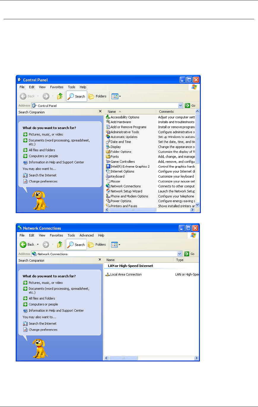
3. Open the Windows® Control Panel.
4. Double click the Network Connections icon.
Chapter 3 G4 Software
RTMS® G4™ User Manual © 2010 Image Sensing Systems, Inc. 3-18
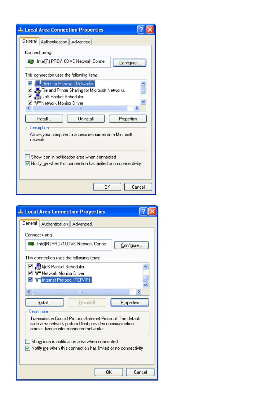
5. Right click over Local Area Connection and select Properties from the listed options.
6. Select Internet Protocol (TCP/IP) from the listed protocols.
Chapter 3 G4 Software
RTMS® G4™ User Manual © 2010 Image Sensing Systems, Inc. 3-19
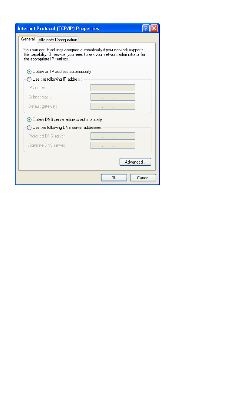
7. Left click the button named Properties.
8. Select Use the following IP address.
9. Set IP address to 128.100.101.1.
10. Set Subnet mask to 255.255.0.0.
11. Click OK. This returns to the Network Connections screen.
12. Click Close. This closes Network Connections.
Chapter 3 G4 Software
RTMS® G4™ User Manual © 2010 Image Sensing Systems, Inc. 3-20
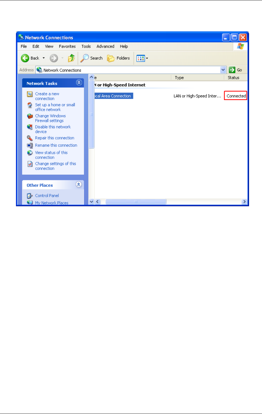
13. Examine the Network Connections screen. Status should indicate Connected. This
verifies that the RTMS and the computer are connected.
14. Start WinRTMS.
15. Select Communication.
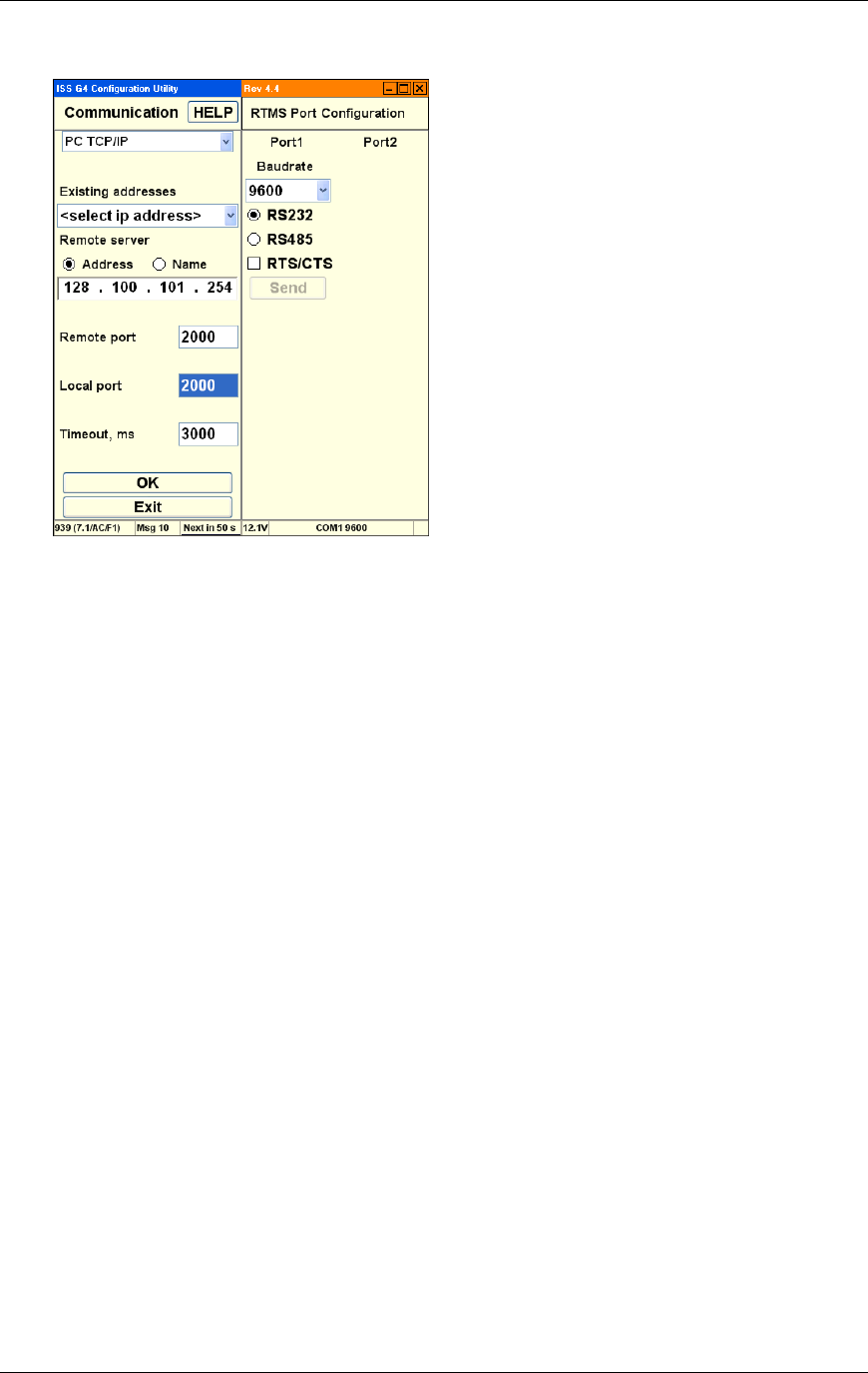
16. Select TCP/IP from the drop down below the Help button.
17. Enter the IP address in the Remote Server field. This default address is 128.100.101.254
(set at the factory).
18. Set Remote Port to 2000.
Chapter 3 G4 Software
RTMS® G4™ User Manual © 2010 Image Sensing Systems, Inc. 3-21
19. Set Local Port to 2000.
20. Click OK.
21. Click Single RTMS.
22. WinRTMS connects to the RTMS sensor and displays the main screen.
23. Proceed with sensor configuration (run the wizard).
Chapter 3 G4 Software
RTMS® G4™ User Manual © 2010 Image Sensing Systems, Inc. 3-22
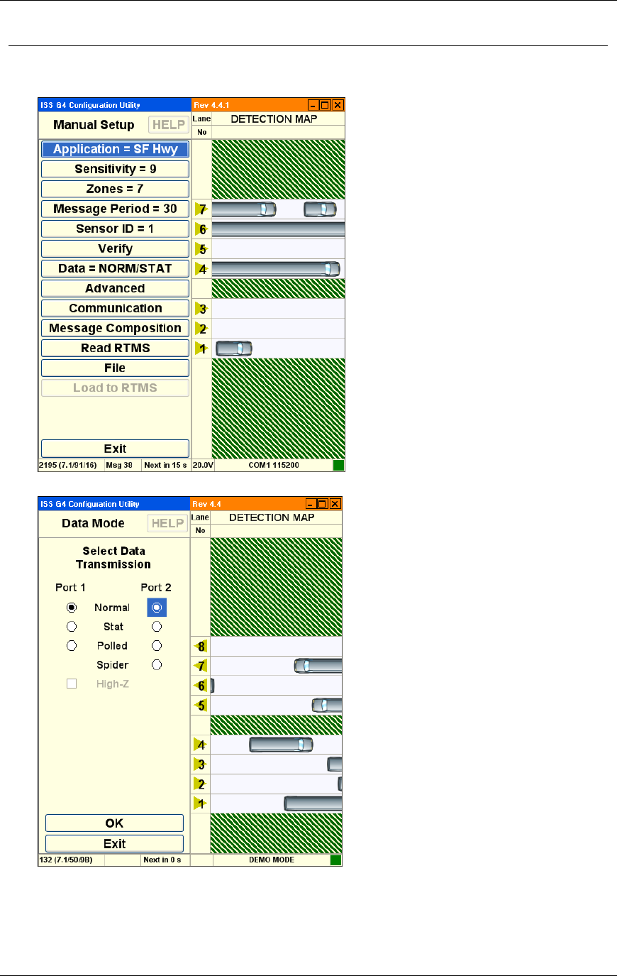
1. The Manual Setup dialog appears. Set Message Period to 30:
2. Select Data Mode. Set Port 2 to Normal, then click OK:
Chapter 3 G4 Software
RTMS® G4™ User Manual © 2010 Image Sensing Systems, Inc. 3-23
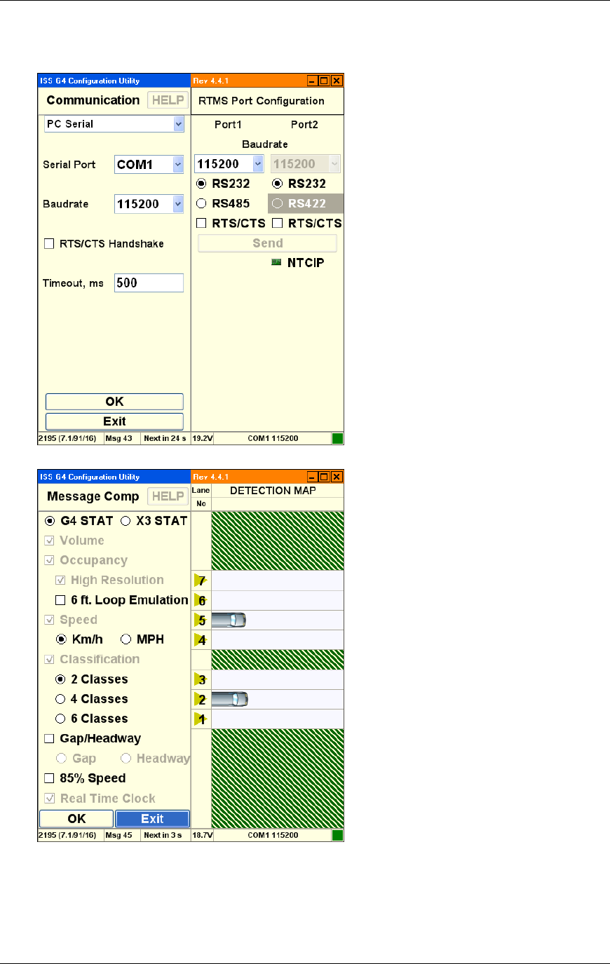
3. Select Communication and check RTMS PC Serial port configuration is set up as follows,
then click OK:
4. Select Message Composition and check settings are as follows:
The NTCIP setup is now complete.
Chapter 3 G4 Software
RTMS® G4™ User Manual © 2010 Image Sensing Systems, Inc. 3-24
How to Set Up Bluetooth Device Communications
Before you can set up Bluetooth device communications, use the manufacturer’s instructions
to install Bluetooth device on your personal computer.
Configuring the Bluetooth Device
Once you have installed the Bluetooth device, configure Bluetooth as follows:
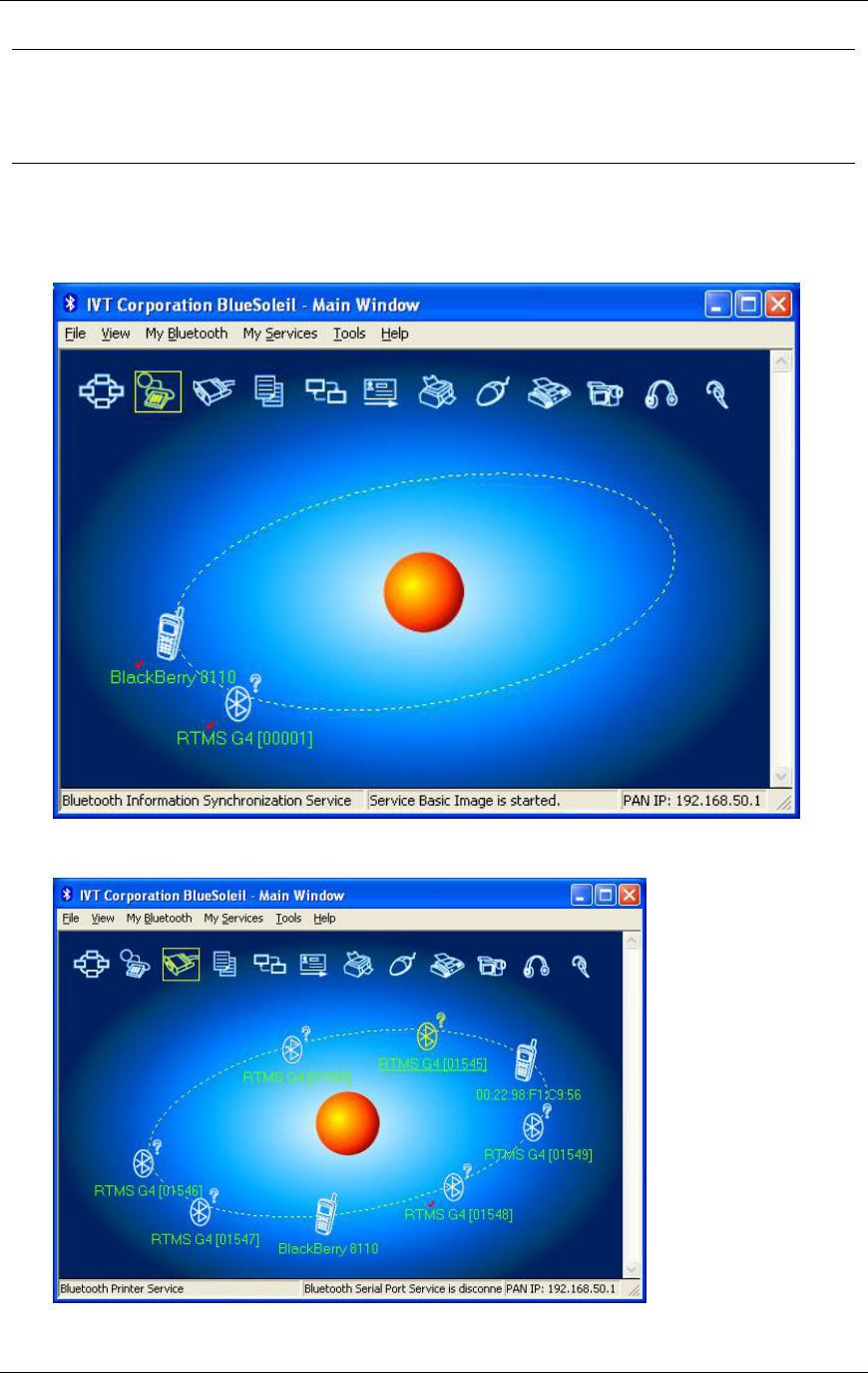
1. Open the Bluetooth utility manager window on your personal computer. The following
example uses IVT Corporation BlueSoleil™ software:
1. To find the G4 Bluetooth device, click on the icon as shown below, or from the Tools
menu, select Find Device:
An alternative method for finding the Bluetooth is to select Bluetooth Device Discovery

Chapter 3 G4 Software
RTMS® G4™ User Manual © 2010 Image Sensing Systems, Inc. 3-25
from My Bluetooth menu:
The software then searches automatically for any Bluetooth device within radio range.
2. If the software does not find the attached Bluetooth device, you may search using the
device name or MAC address. If the name search failed, type in the MAC address.
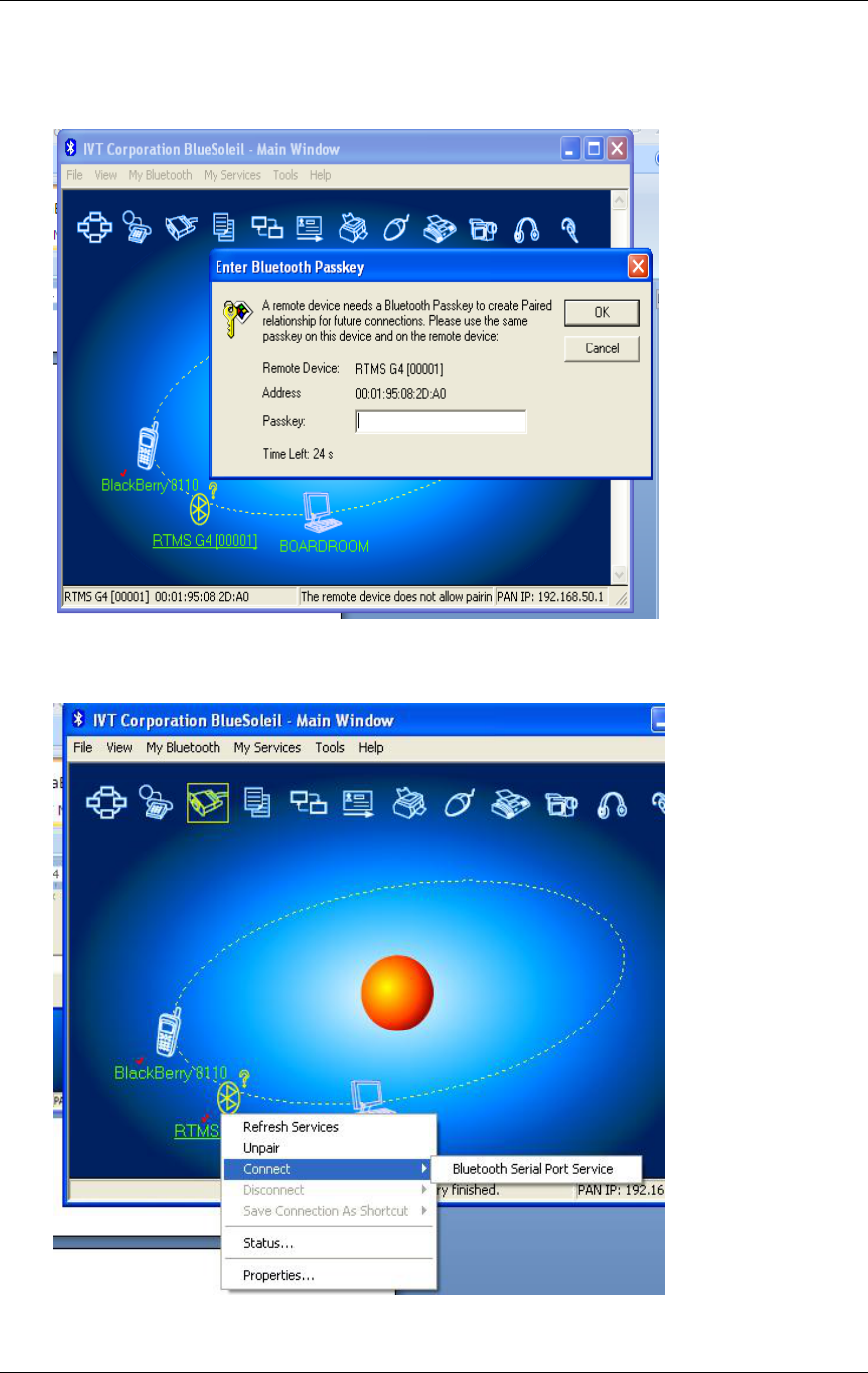
3. Once the G4 Bluetooth is found and showing in the utility window, move the mouse
pointer over the G4 icon, right click on the icon, and select Pair Device:
Chapter 3 G4 Software
RTMS® G4™ User Manual © 2010 Image Sensing Systems, Inc. 3-26
An Enter Bluetooth Passkey dialog appears. The Passkey field supports 16 alphanumeric
characters. You may only change this value using a serial connection. The default RTMS
G4 Bluetooth passkey is admin:
4. Enter the passkey and click OK. Move the mouse pointer over the G4 icon. Right click
and select Connect from the menu. This connects the software to the selected device. In
the example used below, the available connection is a serial port:
5. After you select the correct service, a link connection appears between the RTMS G4
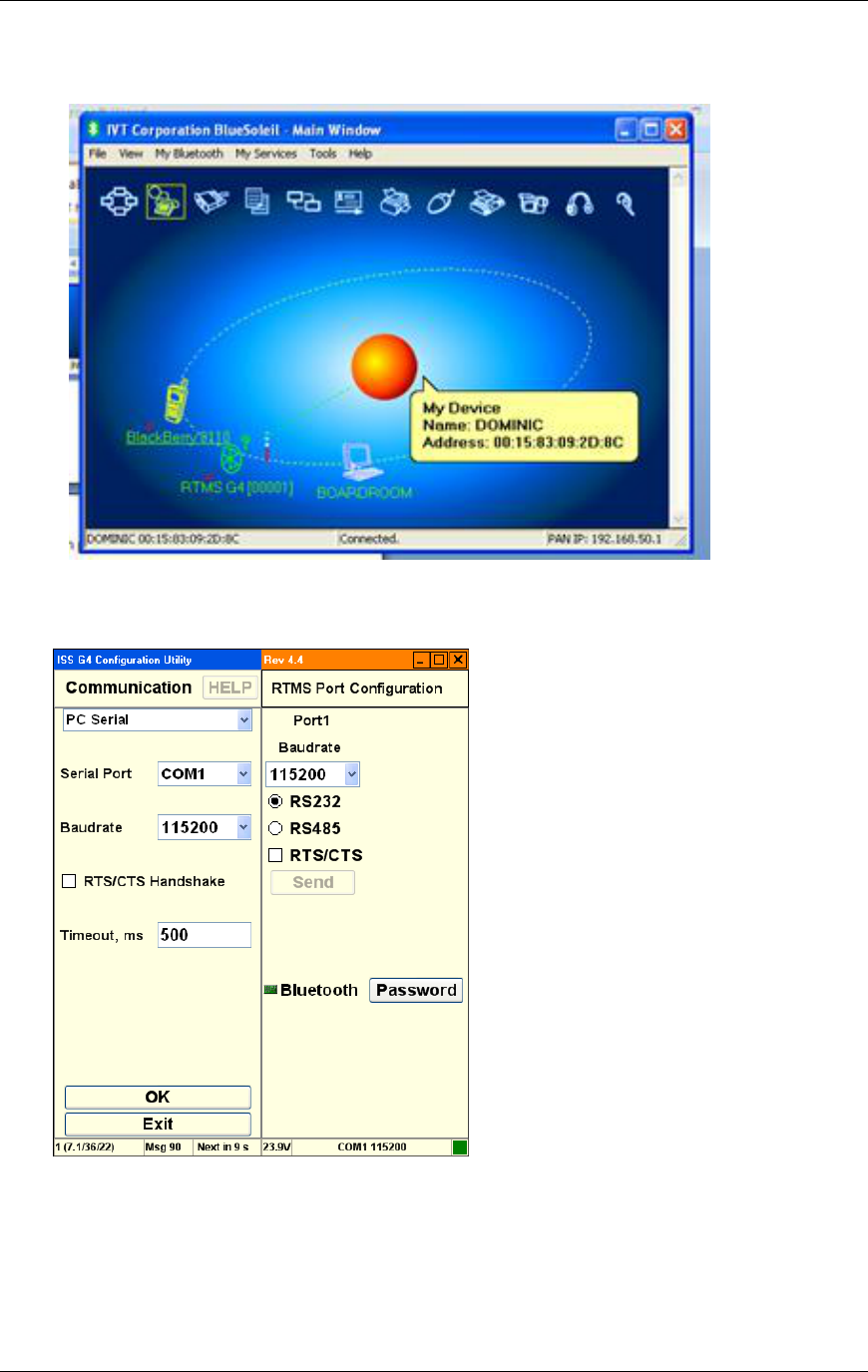
Chapter 3 G4 Software
RTMS® G4™ User Manual © 2010 Image Sensing Systems, Inc. 3-27
and the USB Bluetooth device connected to your workstation. Signal strength is shown
in the utility window. RSSI indication is in terms of signal bars, not in dBm:
6. With the connection made, run the WinRTMS software.
7. If the COM port used by the Bluetooth device is not set to 115200, set it to this value
before continuing.
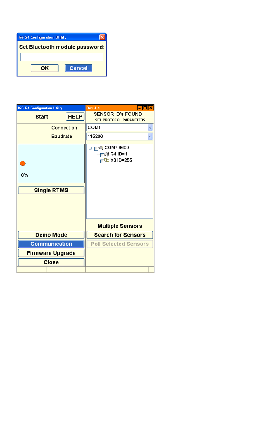
Chapter 3 G4 Software
RTMS® G4™ User Manual © 2010 Image Sensing Systems, Inc. 3-28
8. If you need to enter a new password for the Bluetooth, select Password and enter the
new value.
9. To continue, click OK.
10. To connect to the selected G4 device, select the detected sensor’s COM port number and
baud rate, and select Single RTMS:
11. Once connected, you can proceed with normal WinRTMS and G4 operation as if you are
connected via a serial cable connection. To maintain the connection, you do need to keep
your personal computer within the range of the Bluetooth radio.
12. The Bluetooth radio range is dependent on the type of Bluetooth device you are using.
Bluetooth devices are rated to 100 meters (Class A) or 10 meters (Class B):
Office environment: 10 to 15 meters
Inside a car with clear, transparent windows: 25 meters.
Optical line of sight, no clutter present: 54 meters.
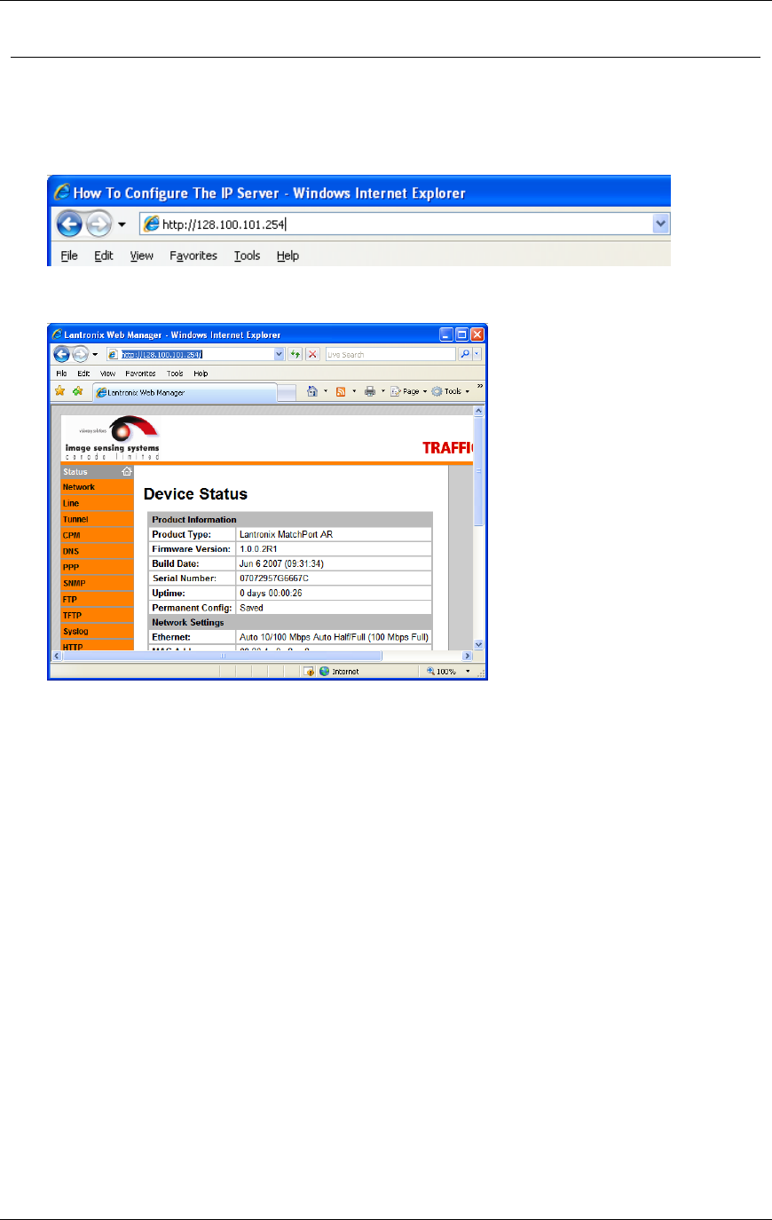
Chapter 3 G4 Software
RTMS® G4™ User Manual © 2010 Image Sensing Systems, Inc. 3-29
How to Configure the IP Server
To configure the IP server (which includes changing the RTMS sensor IP address):
1. Start Internet Explorer®.
2. Type http://128.100.101.254 in the address bar and hit ENTER.
3. Type admin for User name and PASS for password.
4. The Lantronix® interface appears:
5. Please consult Lantronix documentation for information on configuring the IP server.
Serial baud rate communication internally to RTMS is fixed at 115200 – do not adjust.
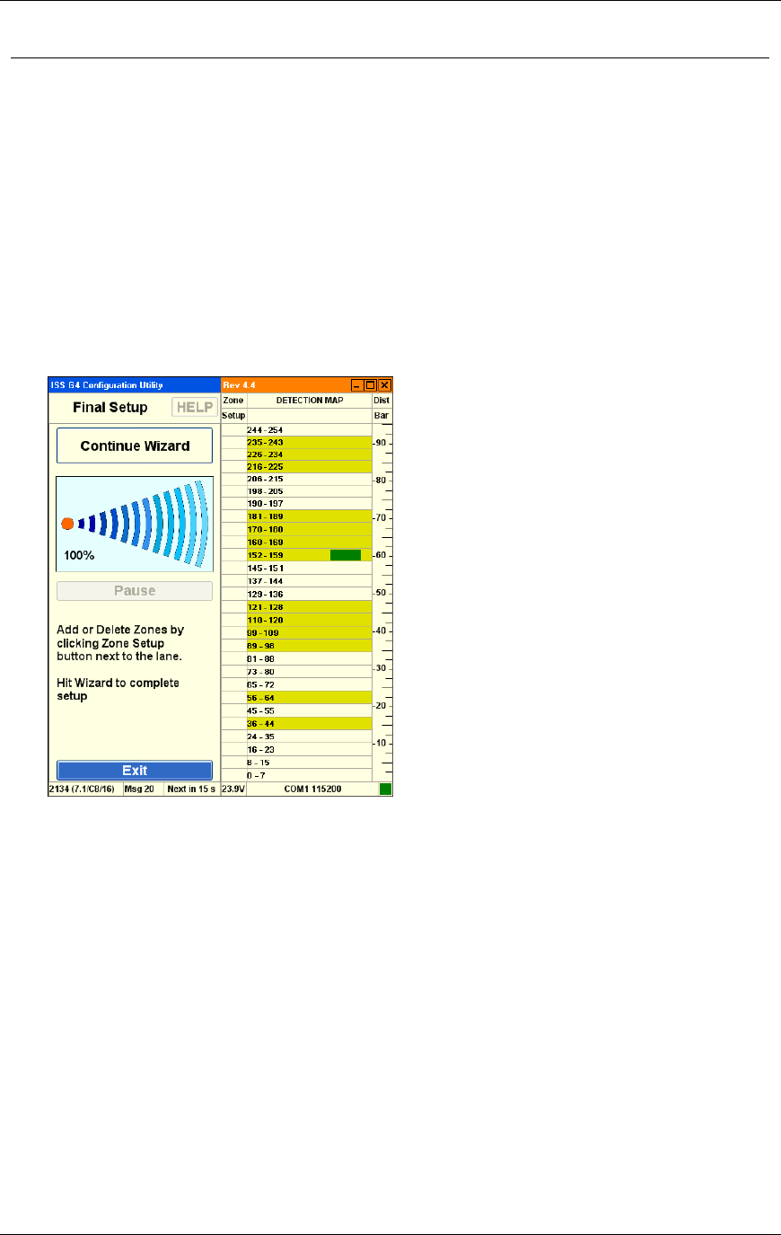
Chapter 3 G4 Software
RTMS® G4™ User Manual © 2010 Image Sensing Systems, Inc. 3-30
How to Use the Automatic Setup Wizard
The automated zone setup process requires free flowing traffic in all lanes of interest. It scans
the range of the RTMS microwave beam and positions up to 12 detection zones—representing
lanes where vehicles are detected.
The WinRTMS software automatically detects traffic in its detection area and configures lane
parameters accordingly. This is a two-stage process:
WinRTMS finds the lanes.
WinRTMS fine tunes the lane assignment/detection parameters.
You may receive warnings while detecting traffic in low-volume lanes. The warning
asks if you would like to continue detection for 1 additional minute. In some cases, such as
when the detector overlaps an exit ramp, continuing the wizard provides little benefit.
To perform Automatic Setup:
1. Click the button named Wizard Setup
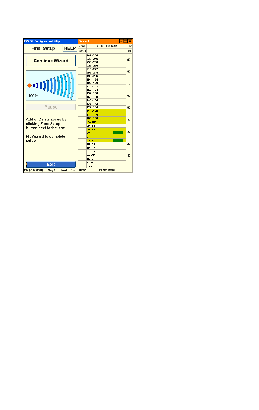
Chapter 3 G4 Software
RTMS® G4™ User Manual © 2010 Image Sensing Systems, Inc. 3-31
2. The resulting zone setup is presented for approval on the detection map when the Progress
Bar reaches its 100% point. The wizard sets sensitivity and positions detection zones
where vehicles are detected.
Using the blips, confirm visually that the proposed location of lanes corresponds to the
lanes you wish to include in the setup.
3. Click the Zone Setup buttons to add or delete zones until desired number and position are
left.
4. Zones can be added or deleted in Fine Tune later as well.
5. Click the Continue Wizard button again to complete the setup.
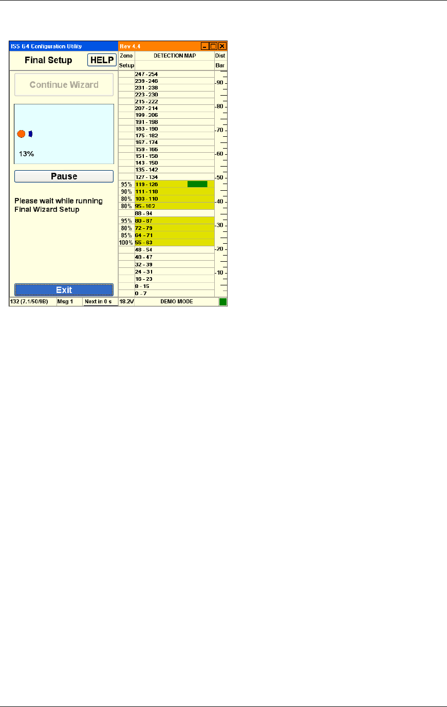
Chapter 3 G4 Software
RTMS® G4™ User Manual © 2010 Image Sensing Systems, Inc. 3-32
Final Setup:
The Wizard continues the automatic setup to a final Zone Setup unless stopped by clicking the
Pause button. (You can click the Pause button to avoid contaminating the process if traffic
slows down momentarily or there is a large gap in the traffic flow.)
On completion, the final positions of the detection zones will be displayed.
Watch the vehicle icons on the right side of the screen and look for possible "Splashing" of
vehicles in one lane into another adjacent lane also. (Trucks are responsible for most
"splashing".)
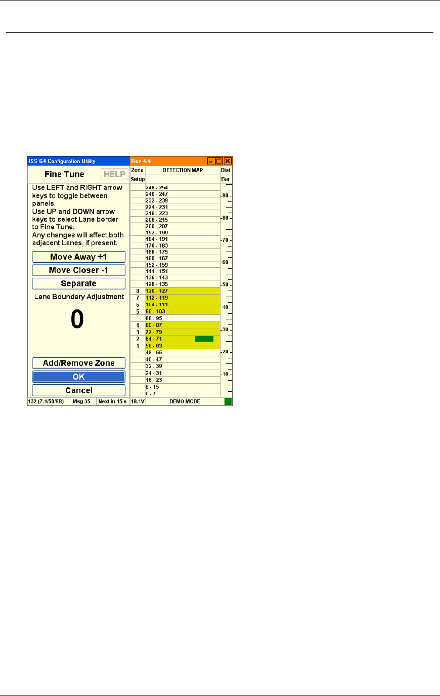
Chapter 3 G4 Software
RTMS® G4™ User Manual © 2010 Image Sensing Systems, Inc. 3-33
How to Fix Splashing
Splashing occurs when a vehicle from one lane triggers a detection in another lane. Lane
changes are one cause of splashing. Narrow lanes or incorrect boundaries are other common
causes.
1. Start the WinRTMS software.
2. Select Manual Settings from the listed options.
3. Select Zones from the listed options.
4. Select Fine Tune from the listed options.
5. To fix splashing, select a Zone No. and boundary between zones by using left click or
SPACE.
6. Use the Move Away and Move Closer buttons to change the boundary by a single micro
slice at a time. Observe the effect on detection on the Fine Tune or Manual Setup Screen.
The boundary move affects the zones on either side, reducing one and enlarging the
other.
A counter shows the amount of shift at any time. This counter resets when you select
the next boundary.
By selecting Add/Remove Zone button you can change the number of zones and
create wider zones spanning more than one lane.
The same two mechanisms allow you to perform the entire zone setup process
manually, by adding zones and moving their boundaries manually.
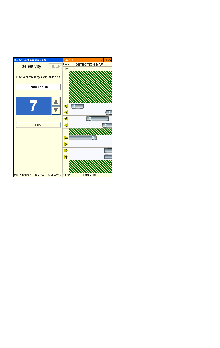
Chapter 3 G4 Software
RTMS® G4™ User Manual © 2010 Image Sensing Systems, Inc. 3-34
How to Adjust Sensitivity
Sensitivity adjustments may be necessary to detect small vehicles, or to reduce splashing.
1. Start the WinRTMS software.
2. Select Manual Settings from the listed options.
3. Select Sensitivity from the listed options.
Increase sensitivity (if needed) to detect small vehicles.
Reduce sensitivity if the button turns red. (Sensitivity is too high.)
Adjust sensor aim if small vehicles in close or far lanes are missed. Tilt the sensor
towards the zones with poor detection.
Do not increase sensitivity to compensate for improper aiming.
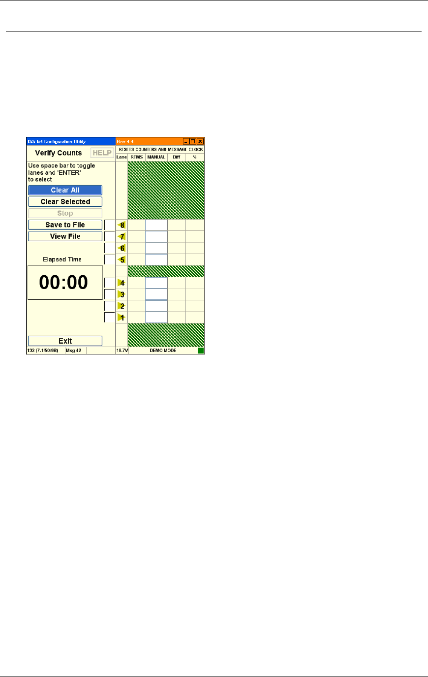
Chapter 3 G4 Software
RTMS® G4™ User Manual © 2010 Image Sensing Systems, Inc. 3-35
How to Verify Counts
The verification of a good zone setup is an essential part of the installation. In it we compare
RTMS volume measurements over a period of time to a manual (visual) count for the same
interval. Use of a hand-held tally counter is recommended.
1. Start the WinRTMS software.
2. Select Manual Settings from the listed options.
3. Select Verify from the listed options.
4. Select which lanes you wish to verify by checking their adjacent boxes. Unchecked lanes
will remain unchanged.
5. Clear the checked RTMS data counters by clicking the Clear Selected button or by
clicking Clear All.
6. In the selected lanes, count vehicles as they cross the RTMS beam starting immediately
after hitting the Start button.
7. Several observers may be enlisted in the process, with each observer counting traffic in a
different lane. The RTMS Count for each selected lane (zone) will be updated as vehicles
pass.
8. Continue counting until each lane has a count of about 50 vehicles; this will usually take
several minutes. An Elapsed Time counter shows you the interval.
9. Click the STOP button when there is a gap in the traffic and immediately stop your
manual counting on all lanes.
10. Highlight a Manual Count box and enter the manual count for the zone in the
corresponding box.
11. The difference between the RTMS and the manual counts in absolute and percent
deviation terms is immediately displayed. Deviation of more than 5% requires zone setup
correction to improve detection accuracy. The verification process should then be repeated.
12. To save the accumulated results of verification in a text file, click Save to File. Use
normal Windows procedures to name and save the file using the Save As dialog. Similarly
click View File to be shown verification results previously saved.
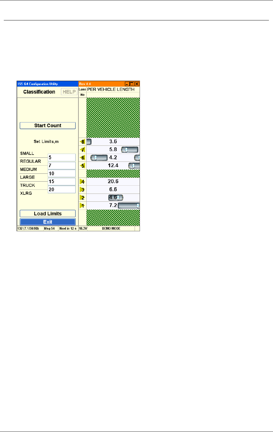
Chapter 3 G4 Software
RTMS® G4™ User Manual © 2010 Image Sensing Systems, Inc. 3-36
How to Modify Vehicle Classifications
The correct classification of vehicles by length requires good breakpoints.
1. Start the WinRTMS software.
2. Select Manual Settings from the listed options.
3. Select Advanced from the listed options.
4. Select Classification from the listed options.
The Classification screen allows the editing of the five length breakpoints above Small
vehicle: Reg, Med, Large, Truck and XLong.
For best results, ensure that differences between length breakpoints are greater than 10
ft (3 m) especially for larger vehicles. Small separation values increase potential for
"merging" of classes (vehicle counting errors are the result).
To check the correctness of the breakpoints, start the per vehicle class counter and
compare the accumulated per vehicle classification counts to manual counts for a
period of at least one minute at a time.
To select the number of classes, go to Message Composition in Manual Setup.
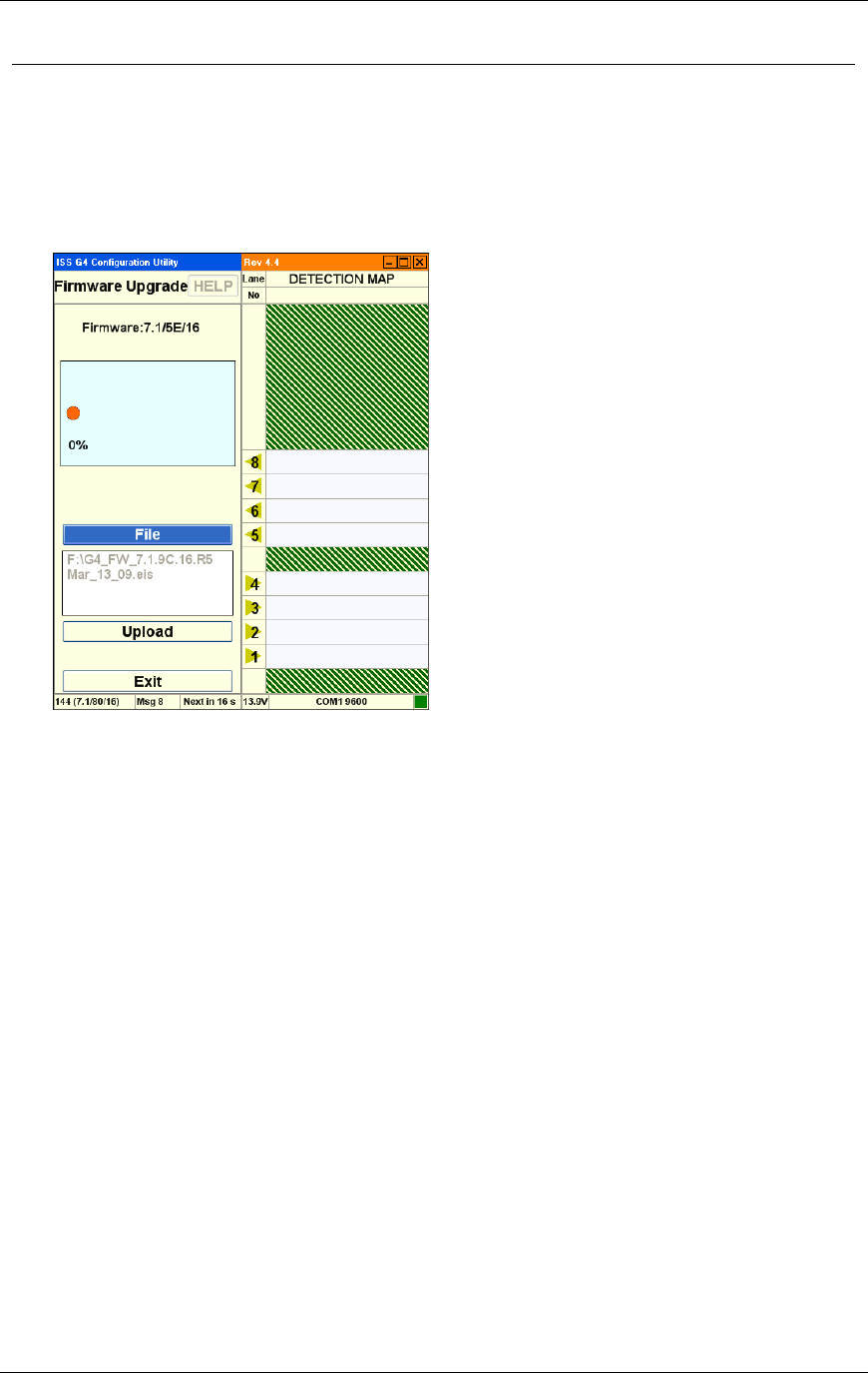
Chapter 3 G4 Software
RTMS® G4™ User Manual © 2010 Image Sensing Systems, Inc. 3-37
How to Upgrade Firmware
Complete the following procedure to upgrade firmware.
1. Start the WinRTMS software.
2. Select Manual Settings from the listed options.
3. Select Advanced from the listed options.
4. Select Firmware Upgrade from the listed options.
5. Ensure that current firmware version is displayed on screen.
6. Proceed to select the firmware file to upload into the RTMS. During upgrade, the progress
bar advances and indicates Percentage Complete. Do not attempt to upgrade without a
solid communication channel.
7. Wait for the message Upgrade Succeeded.
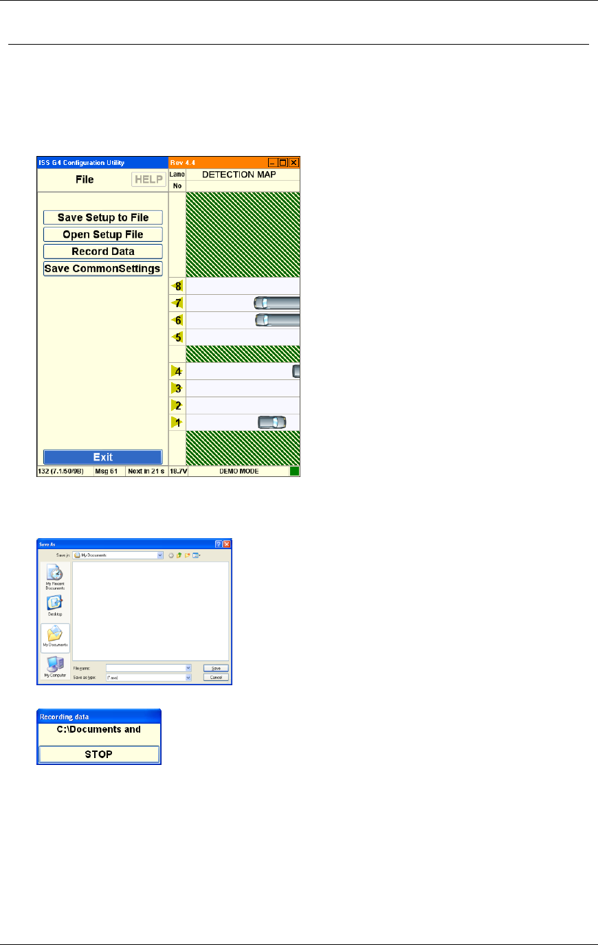
Chapter 3 G4 Software
RTMS® G4™ User Manual © 2010 Image Sensing Systems, Inc. 3-38
How to Record Data
WinRTMS can record RTMS statistical data to a file on the PC's hard disk.
1. Start the WinRTMS software.
2. Select Manual Settings from the listed options.
3. Select File from the listed options.
4. Select Record Data from the listed options.
5. The software prompts you to choose a filename and location on the hard disk. The data file
will have extension .asc.
The software displays a dialog that allows you to stop recording.
6. Click Stop when you are finished.
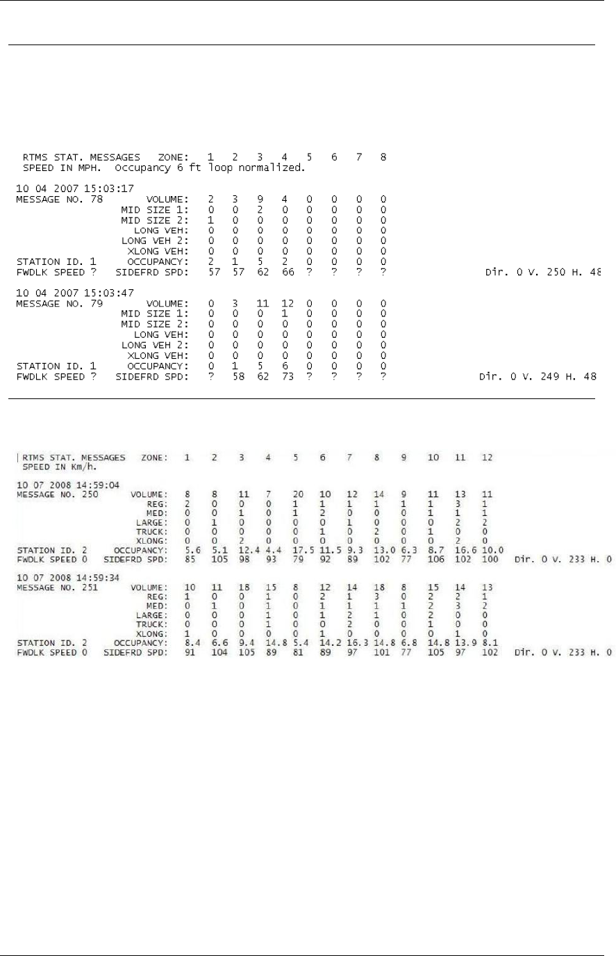
Chapter 3 G4 Software
RTMS® G4™ User Manual © 2010 Image Sensing Systems, Inc. 3-39
X3 Compatible—Statistical Message
The X3 message format will always display all 8 zones even if a lower number are configured
in the setup. The file also provides a voltage reading and a diagnostic indicator in every
message.
Figure 3.3 A sample X3 STAT file with 6 length classes reporting.
G4 Statistical Message
Figure 3.4 Sample G4 STAT file with all 12 lanes and 6 length classes reporting.
Please note:
G4 Statistics Message will have a variable length based on how many lanes are configured.
The designation of vehicle classes will also be the same as shown in the WinRTMS utility.
If Per Vehicle is ON, their data will be ahead of each message period’s statistics.

Chapter 3 G4 Software
RTMS® G4™ User Manual © 2010 Image Sensing Systems, Inc. 3-40
How to Perform Automatic Speed Calibration
Automatic Speed Calibration is intended for use with higher volume traffic, flowing at stable
speeds.
1. Start the WinRTMS software.
2. Select Speed Calibration from the listed options.
3. Use the Up/Down arrow keys to highlight the per-lane Reference Speeds.
The Left/Right arrow keys will decrease or increase the reference in 2 MPH / km/h
increments, which may be estimated or measured (For example: using a radar gun).
4. Click the Time Indicator and increase or decrease the calibration time with the Right and
Left arrow keys. A minimum of 2 minutes is required, although 3 to 5 minutes is better,
depending on traffic volume. The internal speed coefficients will not update if traffic is too
light.
5. Click the Start button and wait as the lane speeds change from their current level towards
the Reference Speeds.
6. You can click the Pause button to avoid contaminating the process if traffic slows down
momentarily or there is a large gap in the traffic flow. You can then Resume. This is
particularly handy when calibrating mid-block applications. You can also change the
Reference Speed during calibration, if more than 2 minutes are remaining. If after
sufficient time the difference to the reference speed is still more than 10%, manual
adjustment may be necessary.
7. Click on Manual if necessary.
8. Click Exit when you are finished.
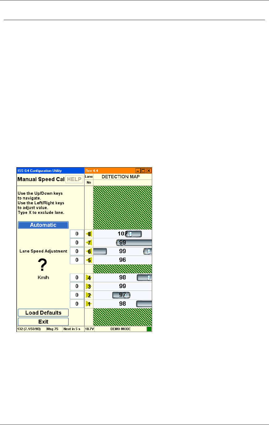
Chapter 3 G4 Software
RTMS® G4™ User Manual © 2010 Image Sensing Systems, Inc. 3-41
How to Perform Manual Calibration
Manual Speed Calibration is intended for very low-volume traffic (For example: traffic volume
of less than 5 vehicles per minute).
Note
To adjust the speeds after Automatic Speed Calibration, DO
NOT load defaults.
ONLY Increase or decrease zone speeds as necessary
It is always best to use Auto Speed Calibration first.
If Not:
You can Load Default parameters and then observe the
actual reported average speed per lane.
Compare the displayed speed measurement to your
estimated average speed in each lane.
1. Start the WinRTMS software.
2. Select Speed Calibration from the listed options.
3. Use Up/Down, Left/Right arrow keys to select a zone and adjust up or down in 2 MPH or
km/h increments; as an example, if speed readings are 10 MPH too low, increase that
lane's speed by 10. The new coefficients take effect immediately.
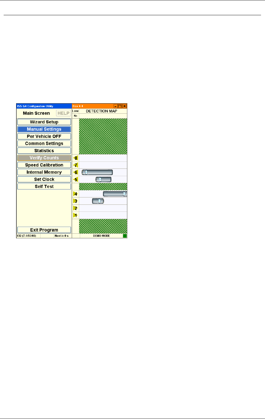
Chapter 3 G4 Software
RTMS® G4™ User Manual © 2010 Image Sensing Systems, Inc. 3-42
How to Create Common Settings
Setup Parameters are often common to all sensors. For example, the sensors in a mid-block
deployment or string of detection stations along the same highway. To save the installer time
and effort in repeatedly entering the same parameters in each site, a group of settings is defined
as common settings. Common settings allow you to specify the basic parameters for an entire
group of sensors.
To create common settings:
1. Start the WinRTMS software.
2. After the parameters on the current RTMS are set to their desired values, select Manual
Settings:
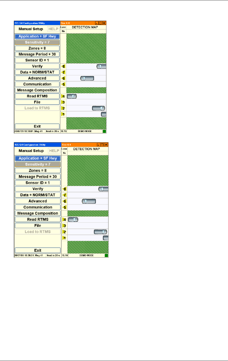
Chapter 3 G4 Software
RTMS® G4™ User Manual © 2010 Image Sensing Systems, Inc. 3-43
The Manual Setup dialog appears:
3. From the Manual Setup dialog, select File:
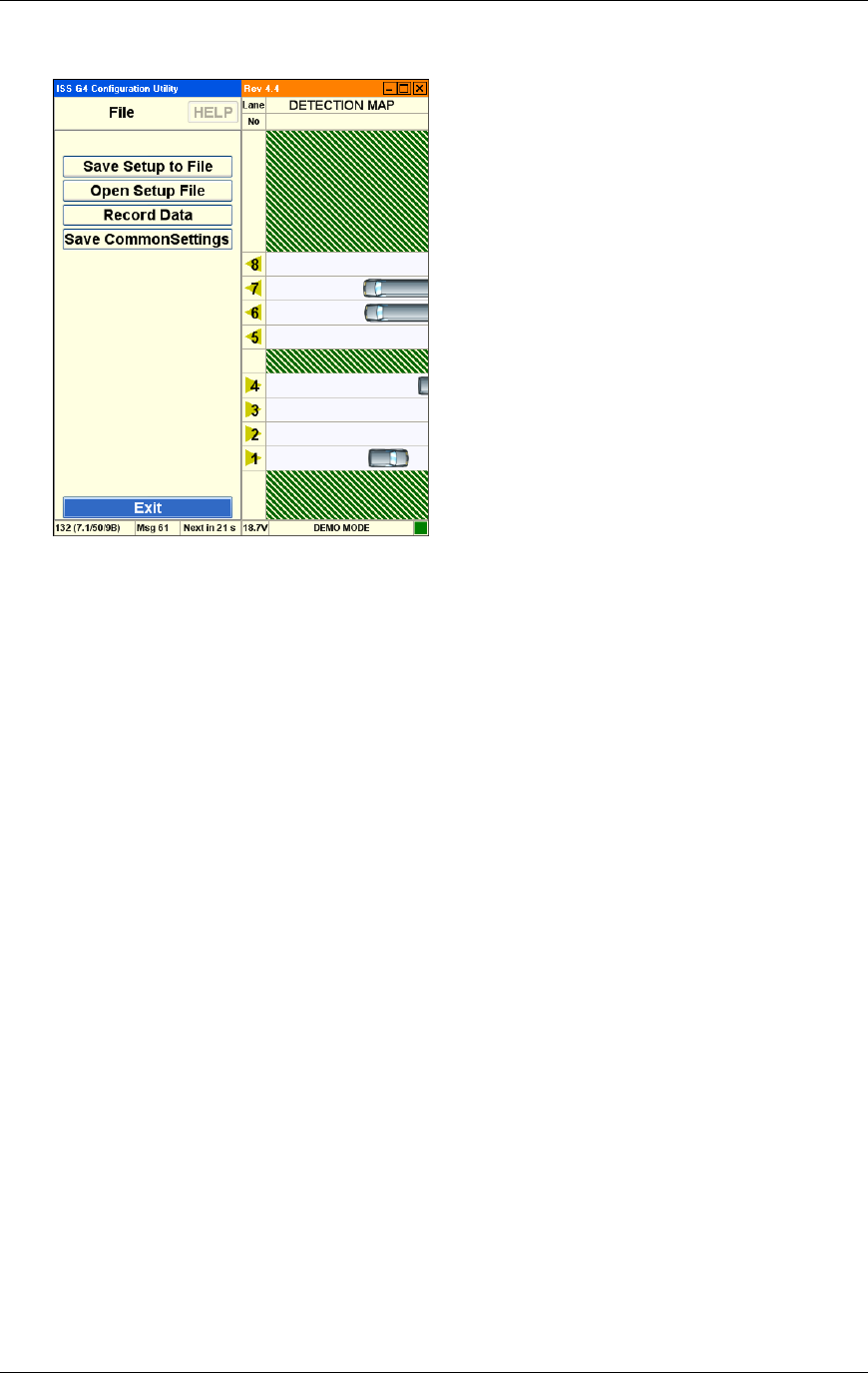
Chapter 3 G4 Software
RTMS® G4™ User Manual © 2010 Image Sensing Systems, Inc. 3-44
4. From the File dialog that appears, select Save Common Settings:
This saves the current settings. They will then be available to be loaded into other RTMS
units in whole or in part depending on requirements. WinRTMS maintains a single set of
common settings. The settings can be overwritten at any time.
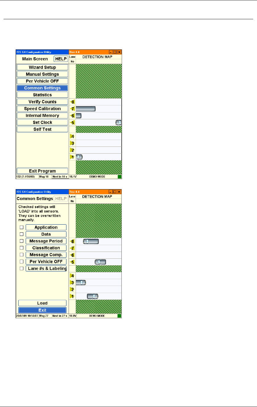
Chapter 3 G4 Software
RTMS® G4™ User Manual © 2010 Image Sensing Systems, Inc. 3-45
How to Apply Common Settings
1. Start the WinRTMS software.
2. Select Common Settings from the listed options:
3. The common settings dialog appears:
4. Check the boxes on the sides of the displayed parameters to define which parameters are
defined as common settings.
5. Click Load to send the common parameters to the RTMS sensor.
6. Click Exit to return to the main screen.

Chapter 3 G4 Software
RTMS® G4™ User Manual © 2010 Image Sensing Systems, Inc. 3-46
How to Save a Setup File to the Hard Disk
1. Start the WinRTMS software.
2. Select Manual Settings.
3. Select File.
4. Select Save Setup To File and follow standard Windows procedures to save the setup
parameters.
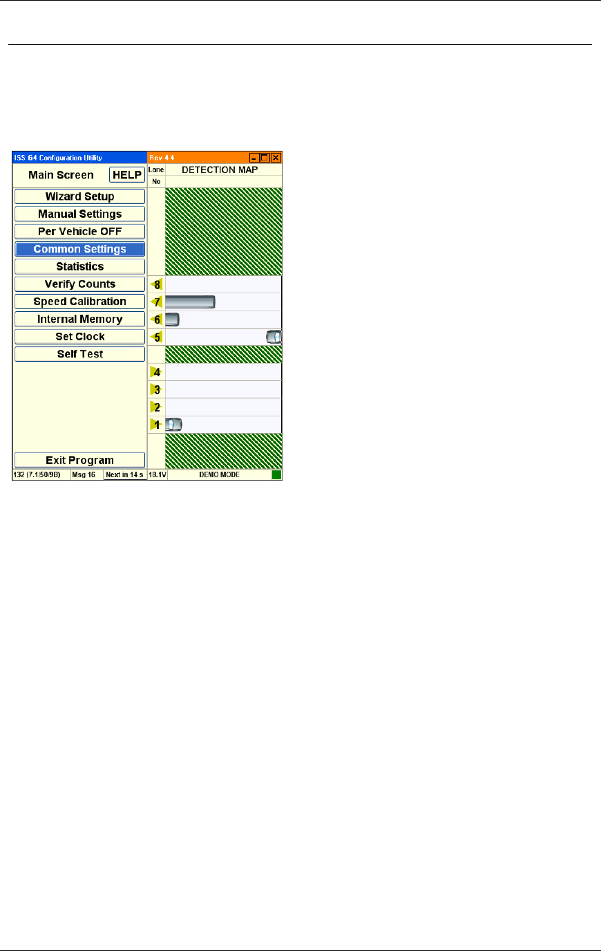
Chapter 3 G4 Software
RTMS® G4™ User Manual © 2010 Image Sensing Systems, Inc. 3-47
RTMS Workspace
The RTMS workspace is vertically divided into two separate panels. The title bar runs
horizontally across the top of the workspace. The status bar runs horizontally across the bottom
of the workspace.
Figure 3.5. RTMS Workspace
WinRTMS Setup Utility. This contains a variety of controls used to configure the
WinRTMS detector functions.
WinRTMS Detection Map. This contains controls that display the active traffic
visualization.
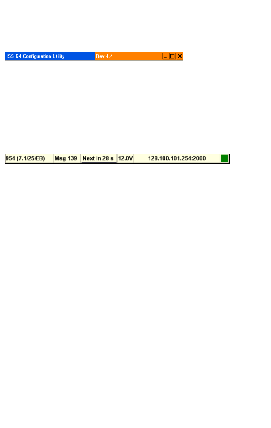
Chapter 3 G4 Software
RTMS® G4™ User Manual © 2010 Image Sensing Systems, Inc. 3-48
RTMS Title Bar
The WinRTMS title bar provides basic application size and position controls.
Reposition. Left click and drag the title bar to reposition the entire workspace.
Minimize. Left click the minimize button to minimize the workspace.
Maximize. Left click the maximize button to maximize the workspace.
Exit. Left click the exit button to close the software. You will be prompted to save the file
if the file is unsaved or to save changes if the file has been modified.
RTMS Status Bar
The WinRTMS status bar provides information about the current mode and traffic detection
parameters.
Options are:
The Serial Number and firmware version of the RTMS.
The number of the currently received statistical message.
The countdown timer (in seconds) to the next statistical message.
The current input voltage reading.
The active Communications port and its speed or the current IP address.
The Communications indicator flashes every time there is communication.

Chapter 3 G4 Software
RTMS® G4™ User Manual © 2010 Image Sensing Systems, Inc. 3-49
About RTMS Main Screen
The RTMS main screen is displayed following a successful connection and is the starting point
for accessing other functions.
Note
If WinRTMS determines that the RTMS is of earlier
firmware revision than 7.1, it will automatically launch
WinRTMS version 3.6 if installed on the computer. Please
refer to RTMS User Manual Issue 4.0 for this setup and
operation.
Once communication with the RTMS is established, the Main Screen appears. The RTMS is
now ready to be calibrated.
The left panel consists of a list of function buttons.
The right panel displays the detection map with the current detection zones and real time
detections indicated by moving vehicle icons.
Options you can click are displayed inside buttons.
Plain text, such as Main Screen and Detection Map are used to indicate the current
screen.
You cannot click these text descriptions.
Always click buttons to change the screen or modify settings.
The Factory setting may not show zones and/or vehicles.
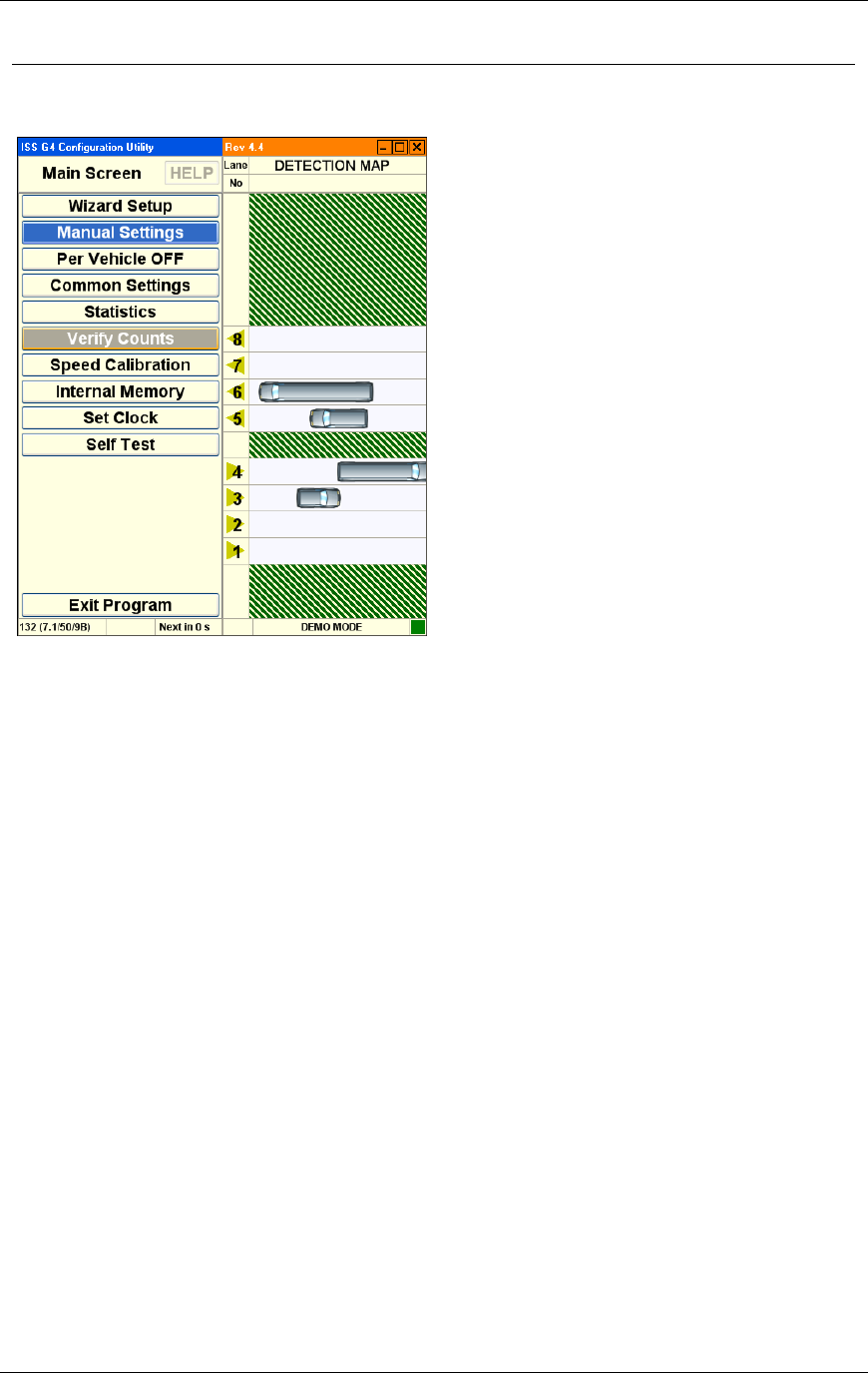
Chapter 3 G4 Software
RTMS® G4™ User Manual © 2010 Image Sensing Systems, Inc. 3-50
RTMS Main Screen
Options are:
Help. Opens a second screen with link to online manual pages.
Wizard Setup. Starts the wizard setup process.
Manual Settings. Displays the manual setup screen.
Per Vehicle OFF. Turning On per vehicle adds the Time stamp, Lane Number,
Classification, Speed and Dwell Time of every vehicle in real time. This added
information can create a huge file in a short time if saving Statistical information to
memory. It will also stream per vehicle information when Data Mode is set to Stat, and
you expect to receive data only every Message Period.
Common Settings. Displays the common settings screen.
Statistics. Displays the statistic screen.
Verify Counts. Displays the verify counts screen.
Speed Calibration. Displays the speed calibration screen.
Internal Memory. Displays the internal memory screen.
Set Clock. Synchronizes the RTMS clock with your computer clock.
Self Test. Displays the self test screen.
Exit. Closes the software. You will be prompted to save the file if the file is unsaved or to
save changes if the file has been modified.
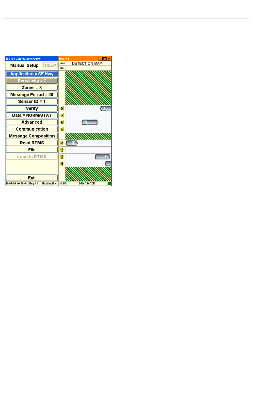
Chapter 3 G4 Software
RTMS® G4™ User Manual © 2010 Image Sensing Systems, Inc. 3-51
RTMS Manual Setup
The WinRTMS manual setup screen displays options that allow you to manually configure the
G4 or RTMS software.
Options are:
Application. This option displays a list of different sensing modes such a side-fired,
intersection, and forward looking. Select the mode that best matches your hardware
configuration and detection requirements.
Sensitivity. This option displays sensitivity adjustment parameters used to calibrate the
sensitivity for a variety of vehicle sizes and sensing applications.
Zones. This option allows you to alter lane numbers, labeling, and to manually adjust zone
position and width.
Message Period. This option allows you to configure the message period for which
statistical reports are generated.
Sensor ID. This option allows you to set the Sensor ID parameter.
Verify. This option allows you to manually verify traffic count results and determine the
percentage error.
Data. This option allows you to control the basic data mode for a single RTMS device.
Advanced. This option accesses advanced features such as traffic classification options
and firmware upgrade management.
Communication. This option allows you to specify communication parameters such as
Port and Baud Rate.
Message Composition. This option allows you to configure the content and format of
each statistical message.
Read RTMS. This option transfers the current setup parameters from the RTMS sensor to
the software.
File. This option allows you to save and load configuration files.
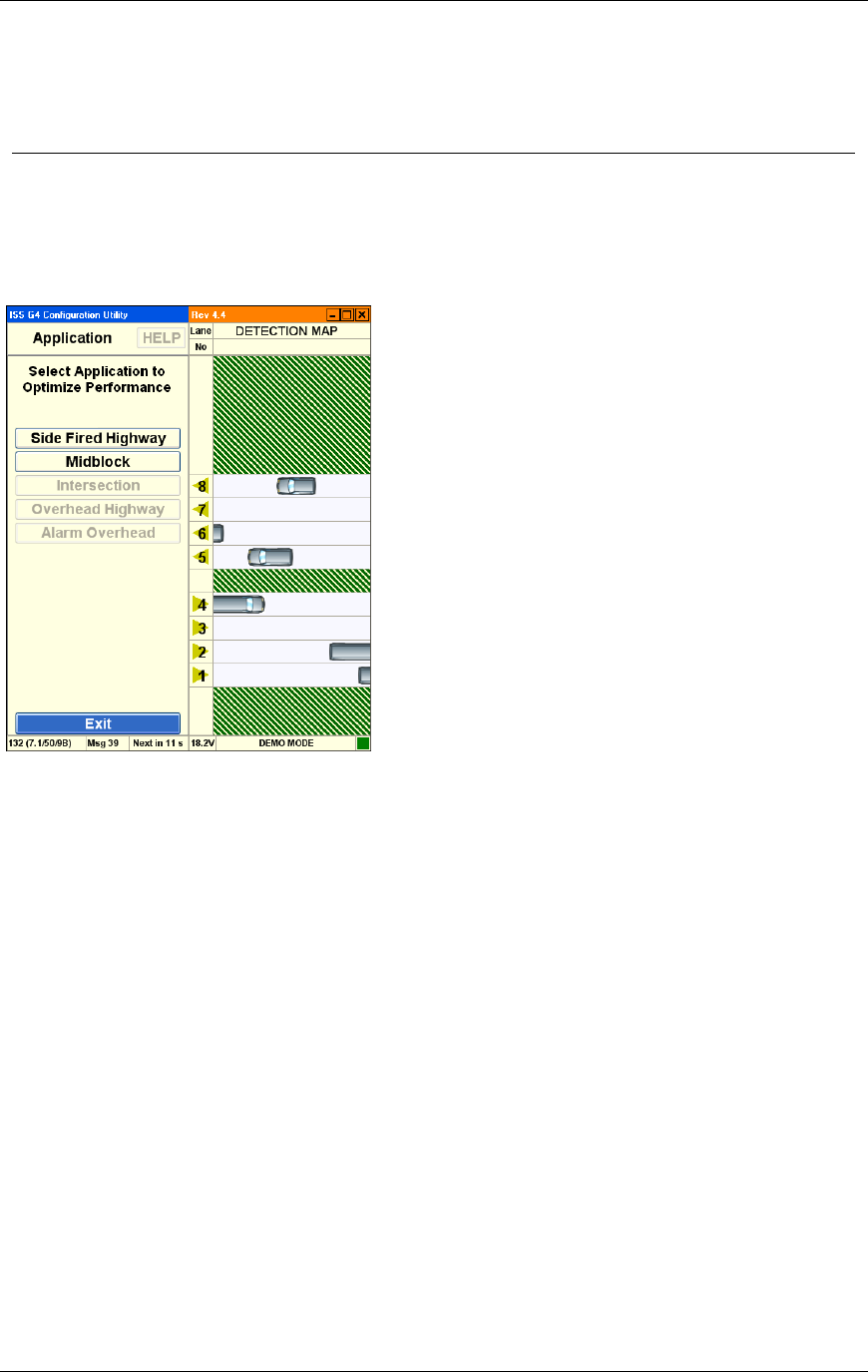
Chapter 3 G4 Software
RTMS® G4™ User Manual © 2010 Image Sensing Systems, Inc. 3-52
Load To RTMS. Clicking this button loads the current configuration (running on the
WinRTMS software) to the RTMS.
Exit. Returns to the main screen.
RTMS Application Options
This screen displays a list of different sensing modes such a side-fired, intersection, and
forward looking. Select the mode that best matches your hardware configuration and detection
requirements.
Options are:
Side Fired Highway. The RTMS detects presence and generates traffic data in up to 12
zones. (Use this option for highway and counting applications where traffic is generally
moving.)
Mid-Block. Similar to Side Fired Highway mode. Use this option for urban areas where
traffic is generally moving but gets congested.
Intersection. The RTMS detects presence only in multiple zones. (No traffic data is
generated) Use this option for Stop-bar detection where traffic is generally stopped.
Forward Looking Highway. The RTMS provides very high presence and per vehicle
Doppler speed accuracy. Volume data in up to 7 speed bins is available. Use this option for
per vehicle speed, speed Enforcement, or red light enforcement.
Alarm Forward Looking. Similar to Forward Looking Highway with programmable
Speed Threshold and real time contact closure when a vehicle exceeds threshold. Use this
option for speed enforcement and warning applications.
Exit. Returns to the main screen.
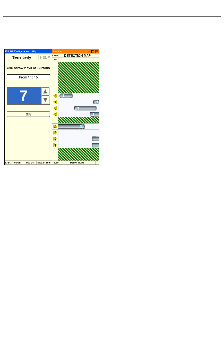
Chapter 3 G4 Software
RTMS® G4™ User Manual © 2010 Image Sensing Systems, Inc. 3-53
RTMS Sensitivity Options
This option displays sensitivity adjustment parameters used to calibrate the sensitivity for a
variety of vehicle sizes and sensing applications.
Options are:
Arrows. Click UP and DOWN arrows on screen or use arrow keys to set Sensitivity.
Initial starting level set to 7, and adjust up or down as necessary.
OK. Activates the new value and returns to the main screen.
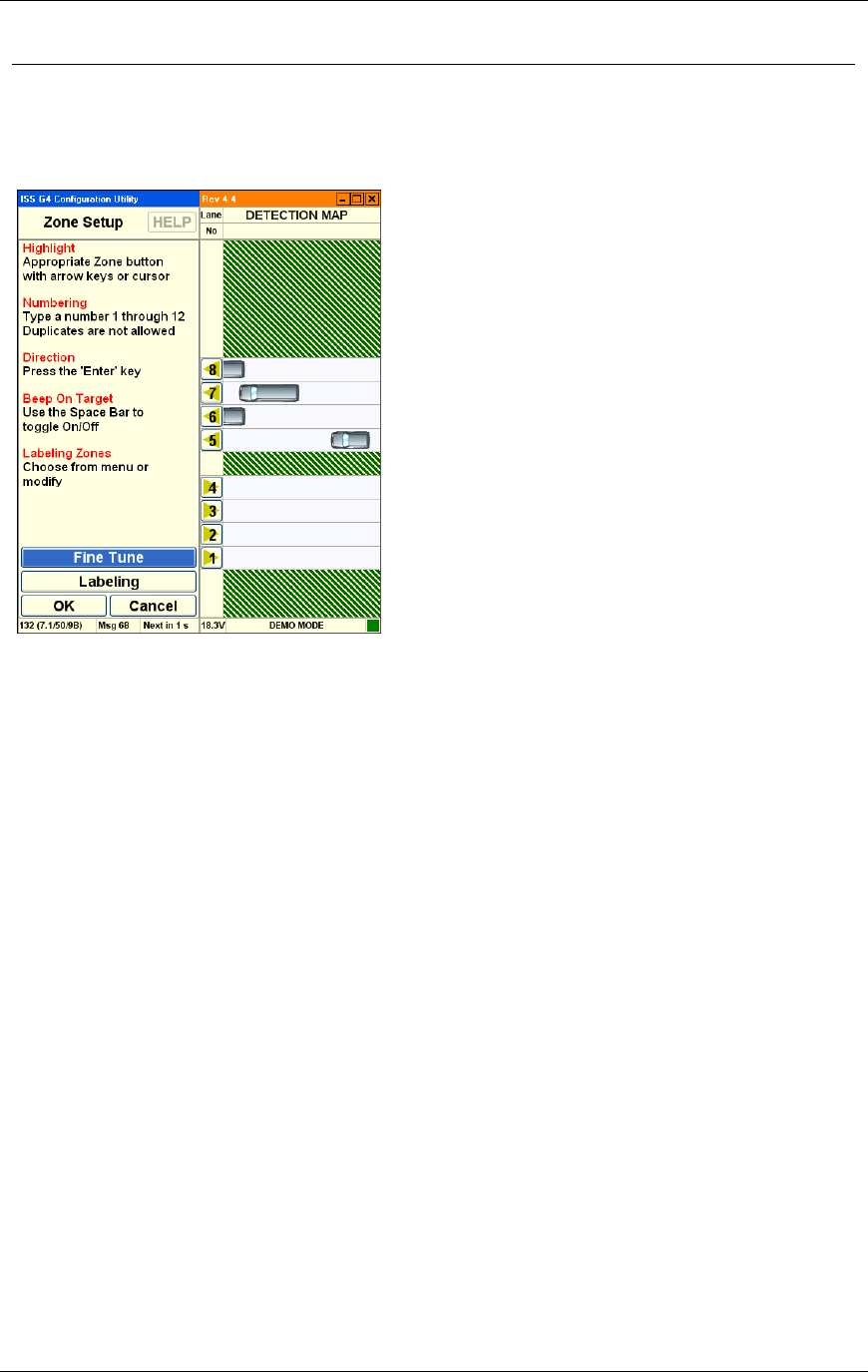
Chapter 3 G4 Software
RTMS® G4™ User Manual © 2010 Image Sensing Systems, Inc. 3-54
RTMS Zone Options
This screen allows you to alter lane number and other related parameters such as beeping and
traffic direction. See How to Fix Splashing.
Options are:
Lane Numbers. A list of lane numbers is displayed.
Once a Lane Number is selected (highlighted), you can:
Re-number the lanes.
Change vehicle icon direction
Turn on a Beep upon detection in that lane (Zone).
The beep is an additional aid in verifying that vehicles you see on the road are
detected properly by the RTMS and reported in the correct Zones.
Fine Tune. If you observe "Splashing" where a single vehicle also shows detection in an
adjacent zone or if vehicles are shown in the wrong lane, this may indicate that the zone
boundary positions do not line up with the lanes. Make sure that the splashing was not
caused by a vehicle changing lanes before using the Fine Tune option.
Labeling. Rename lanes with this option.
OK. Saves changes and returns to the main screen.
Cancel. Returns to the main screen without saving changes.
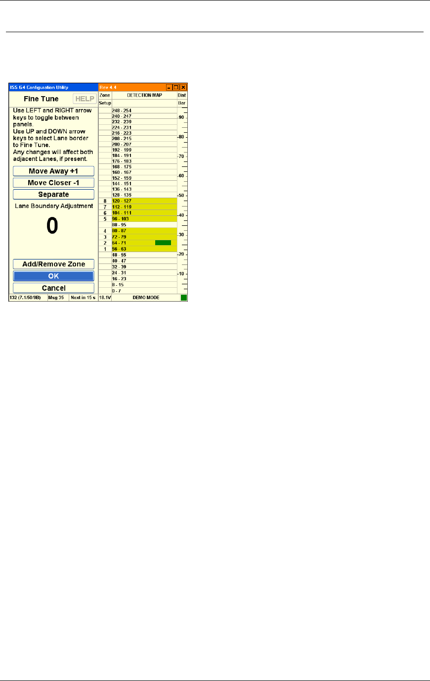
Chapter 3 G4 Software
RTMS® G4™ User Manual © 2010 Image Sensing Systems, Inc. 3-55
RTMS Fine Tune Options
This screen allows you to fine tune zone boundary parameters.
Options are:
Move Away +1. Shifts lane boundaries further away.
Move Closer -1. Shifts lane boundaries closer.
Separate. Inserts a space between lanes (for medians, curbs).
Layer Boundary Adjustment. Displays the amount of adjustment made for the current
iteration. For example: 4.
Add/Remove Zone. Adds a new lane or removes an existing lane.
OK. Saves changes and returns to the main screen.
Cancel. Returns to the main screen without saving changes.
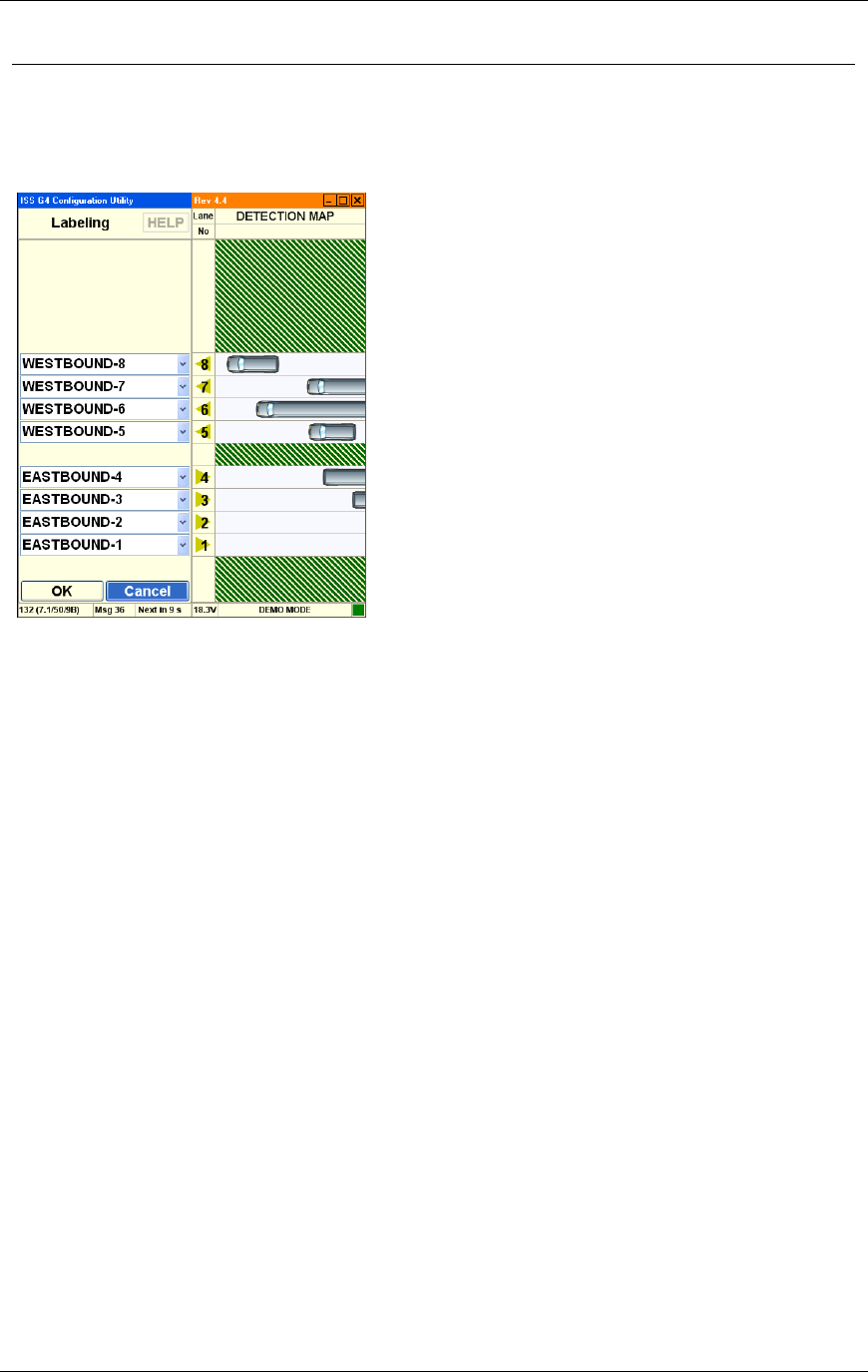
Chapter 3 G4 Software
RTMS® G4™ User Manual © 2010 Image Sensing Systems, Inc. 3-56
RTMS Labeling Options
This screen allows you to customize zone names. (The labeling is stored within the RTMS
sensor and is not transmitted in the statistical message.)
Options are:
Lane Name. Type a new name for the indicated lane.
OK. Saves changes and returns to the main screen.
Cancel. Returns to the main screen without saving changes.
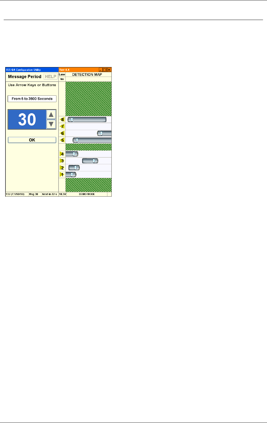
Chapter 3 G4 Software
RTMS® G4™ User Manual © 2010 Image Sensing Systems, Inc. 3-57
RTMS Message Period Options
This screen allows you to configure the message period for which statistical reports are
generated. A 30 second message period is generally used for Real-Time traffic data and 300 to
900 sec (5 to 15 min) for counting applications.
Options are:
Arrows. Click UP and DOWN arrows on screen or use arrow keys to set Message Period
to the desired interval.
OK. Activates the new value and returns to the main screen.
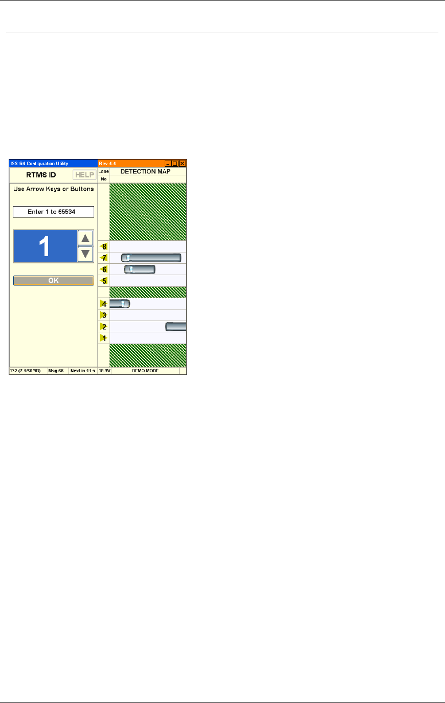
Chapter 3 G4 Software
RTMS® G4™ User Manual © 2010 Image Sensing Systems, Inc. 3-58
RTMS Sensor ID Options
This screen allows you to set the Sensor ID parameter. (Please consult ISS Canada for
assistance designing large serial networks.)
X3 Stat Mode. The Sensor ID range is between 1-254.
G4 Mode. The Sensor ID range is between 1 and 65534.
The Sensor ID must be set only if Polled data mode is used. Units should be assigned unique
ID numbers to avoid data corruption.
Options are:
Text Entry. Use the keyboard to enter an integer to set the Sensor ID to the desired value.
Arrows. Click UP and DOWN arrows on screen or use arrow keys to set Sensor ID to the
desired value.
OK. Activates the new value and returns to the main screen.
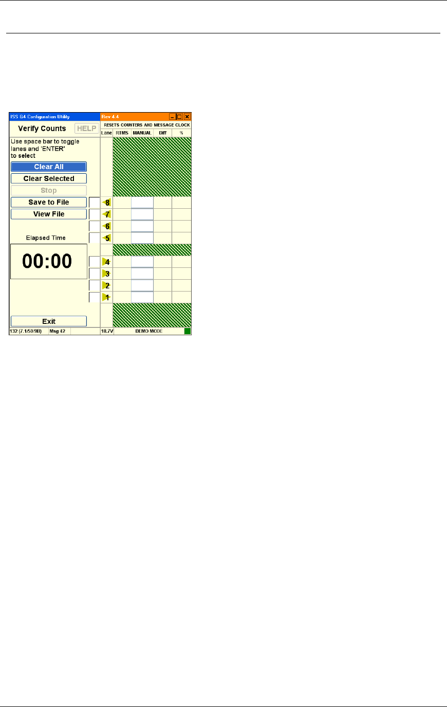
Chapter 3 G4 Software
RTMS® G4™ User Manual © 2010 Image Sensing Systems, Inc. 3-59
RTMS Verify Counts
The verification of a good zone placement is an essential part of the setup. In it we compare
RTMS volume measurements over a period of time to a manual (visual) count for the same
interval. Use of a hand-held tally counter is recommended. See How To Verify Counts.
Options are:
Clear All. This option clears the current values from all the traffic lanes.
Clear Selected. This option clears the current values from the selected traffic lanes.
Stop. This option terminates the counting process.
Save To File. This option allows you to save a count file to the hard disk.
View File. This option allows you to load a count file from the hard disk for review.
Elapsed Time. This option displays the amount of time since count verification started.
Exit. Returns to the main screen.
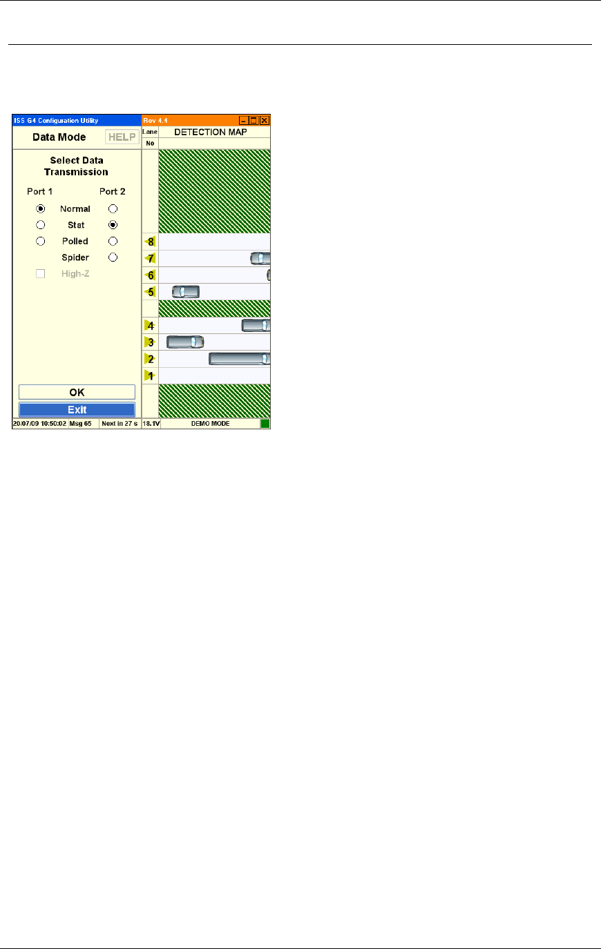
Chapter 3 G4 Software
RTMS® G4™ User Manual © 2010 Image Sensing Systems, Inc. 3-60
RTMS Data Options
The Data Mode determines whether data is Pushed or Pulled from the RTMS unit.
Options are:
Normal. Normal mode sends statistic messages at the end of every Message Period and all
per vehicle information to display vehicle icons, speeds etc.
Stat. Stat mode allows only the statistical messages to be sent at the end of every Message
Period.
Polled. Polled mode only allows the RTMS to upload the statistical data that is currently
stored in its buffer when a specific Sensor ID request is received from an outside source.
Spider. Spider mode configures the RTMS to send data, via the SPIDER protocol, through
port 2. This option only works with SPIDER systems.
High-Z. This option leaves the transmit pin in high-impedance mode. This is only
available in Polled mode.
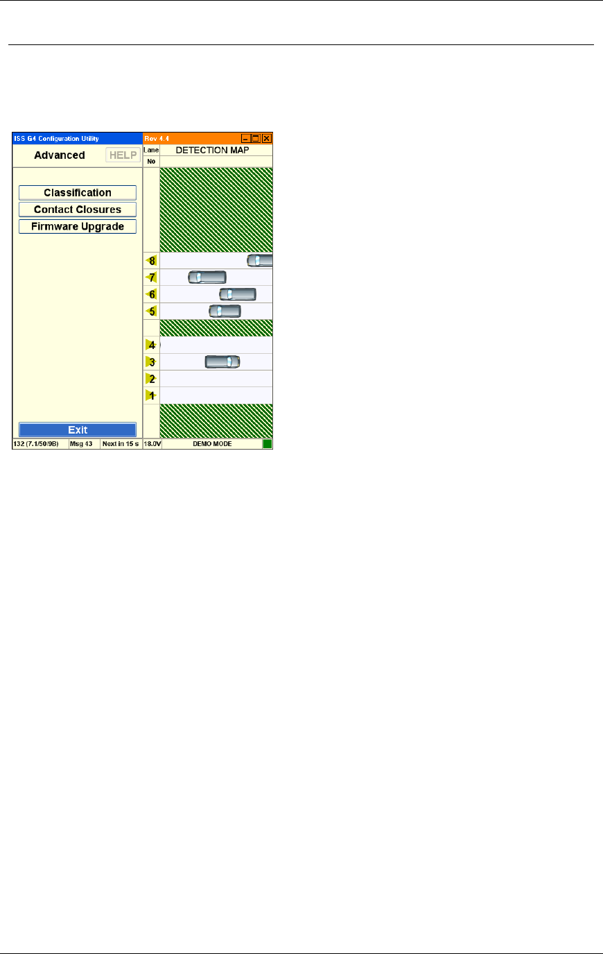
Chapter 3 G4 Software
RTMS® G4™ User Manual © 2010 Image Sensing Systems, Inc. 3-61
RTMS Advanced Options
This screen accesses advanced features such as traffic classification options and firmware
upgrade management.
Options are:
Classification. This option allows you to modify traffic classification options.
Contact Closures. This option allows you to implement real time presence indication in
each detection zone on units with the Contact Closure option installed.
Firmware Upgrade. This option allows you to upgrade to the latest version of ISS Canada
firmware.
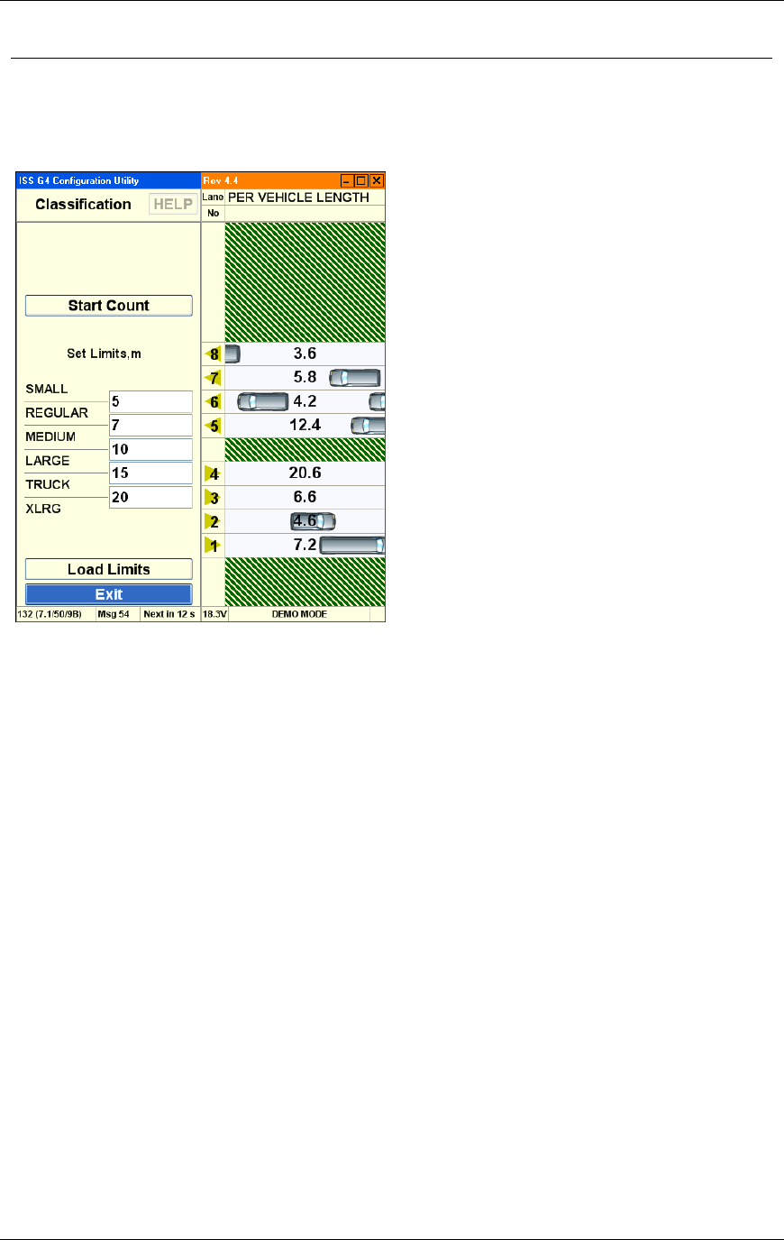
Chapter 3 G4 Software
RTMS® G4™ User Manual © 2010 Image Sensing Systems, Inc. 3-62
RTMS Advanced Classification Options
This screen allows you to specify traffic classification options for vehicles being counted. You
may specify the length of each vehicle type detected in the monitoring period.
Options are:
Start Count. This option starts the count, displaying the number of vehicles of each type
that are detected.
Set Limits. These options allow you to set the maximum length for a category of vehicles.
Depending on the number of classifications selected in Message Composition, either 2,
4 or 6 classes will display.
The number between the two classes (example between Small and Regular) reflects
the break point between the 2 classes.
Load Limits. This option sends the current size parameters to the RTMS sensor.
Exit. Returns to the main screen.
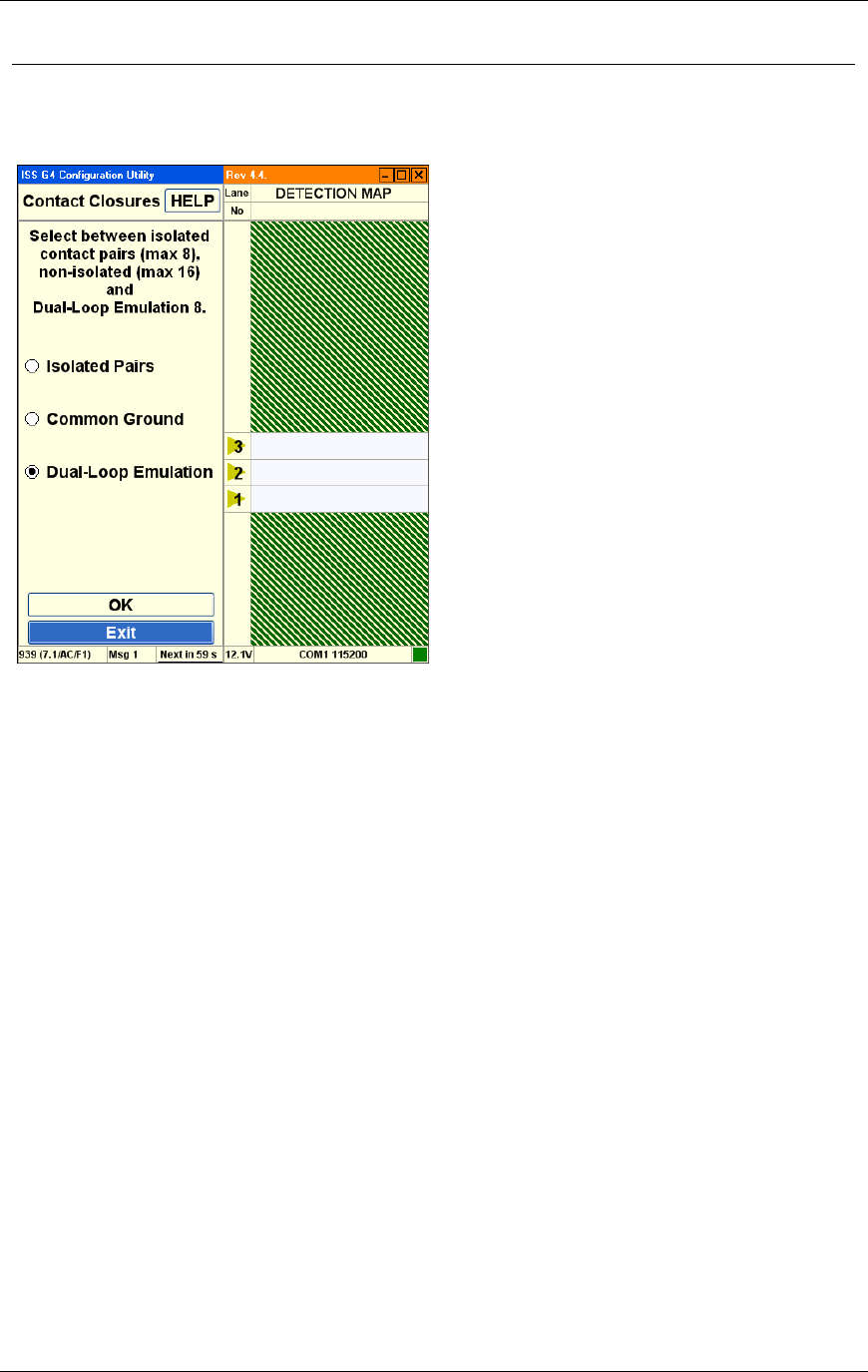
Chapter 3 G4 Software
RTMS® G4™ User Manual © 2010 Image Sensing Systems, Inc. 3-63
RTMS Contact Closures
This screen allows you to select or configure the type of contact closure to be used.
Options are:
Isolated Pairs. This option allows you to isolate contacts from each other. This option
provides 8 zones of detection, and uses two wires per zone. The zones operate completely
independent of each other.
Common Ground. This option allows contacts to share a common ground. This option
provides 12 zones of detection using a common ground.
Dual-Loop Emulation. Double click the "text" to configure dual loop detection
parameters. This option provides 8 zones of detection. This option also provides 8
secondary outputs that can be used to simulate the closure information that is collected
from a dual loop station. Changing the time delay between the first and second loop
outputs is used to adjust the speed information that the controller produces.
Note
Contact closure numbering can be different from the zone
numbering. The closest zone will always associate with
contact closure number 1 irrespective of its zone number.
Contact closure numbering will increase sequentially as they
get further away from the RTMS.
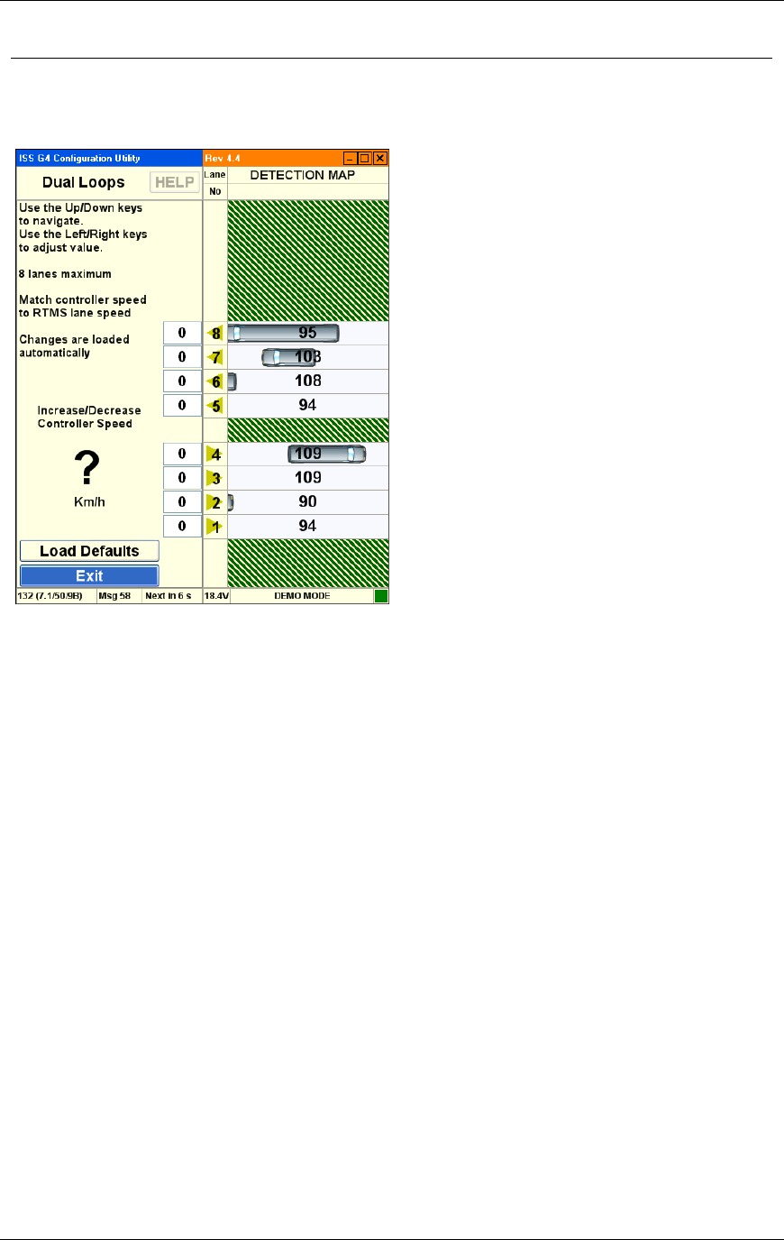
Chapter 3 G4 Software
RTMS® G4™ User Manual © 2010 Image Sensing Systems, Inc. 3-64
RTMS Dual Loop Options
This screen allows you to adjust the controller speed output to match the RTMS speed.
Options are:
Increase/Decrease Controller Speed. This option allows you to synchronize average
vehicle speed at the controller with average vehicle speed at the RTMS sensor.
Load Defaults. Loads factory default settings for speed coefficients.
Exit. Returns to the contact closures screen.
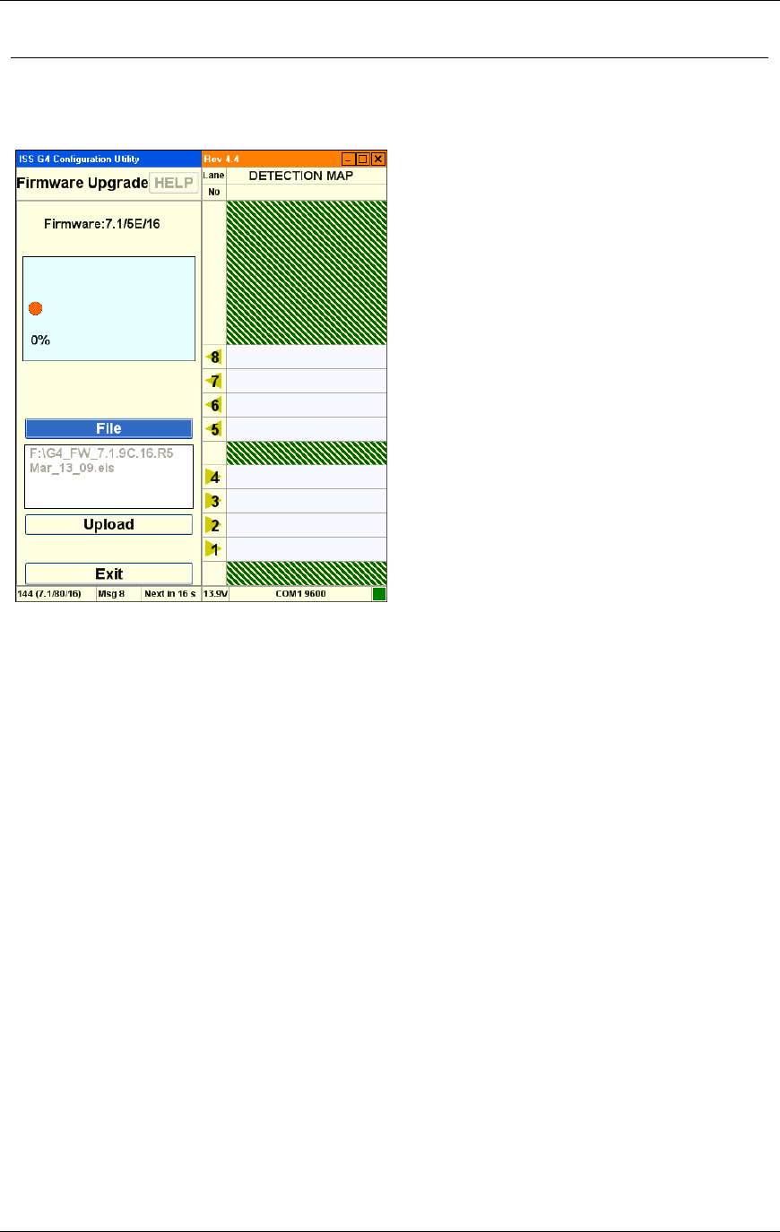
Chapter 3 G4 Software
RTMS® G4™ User Manual © 2010 Image Sensing Systems, Inc. 3-65
RTMS Firmware Upgrade Options
This screen allows you to upgrade firmware.
Options are:
Progress / Message Indicator. Displays current progress and status messages.
File. This option allows you to specify a new firmware file.
Upload. This uploads the firmware file to the sensor.
Exit. Returns to the previous screen.
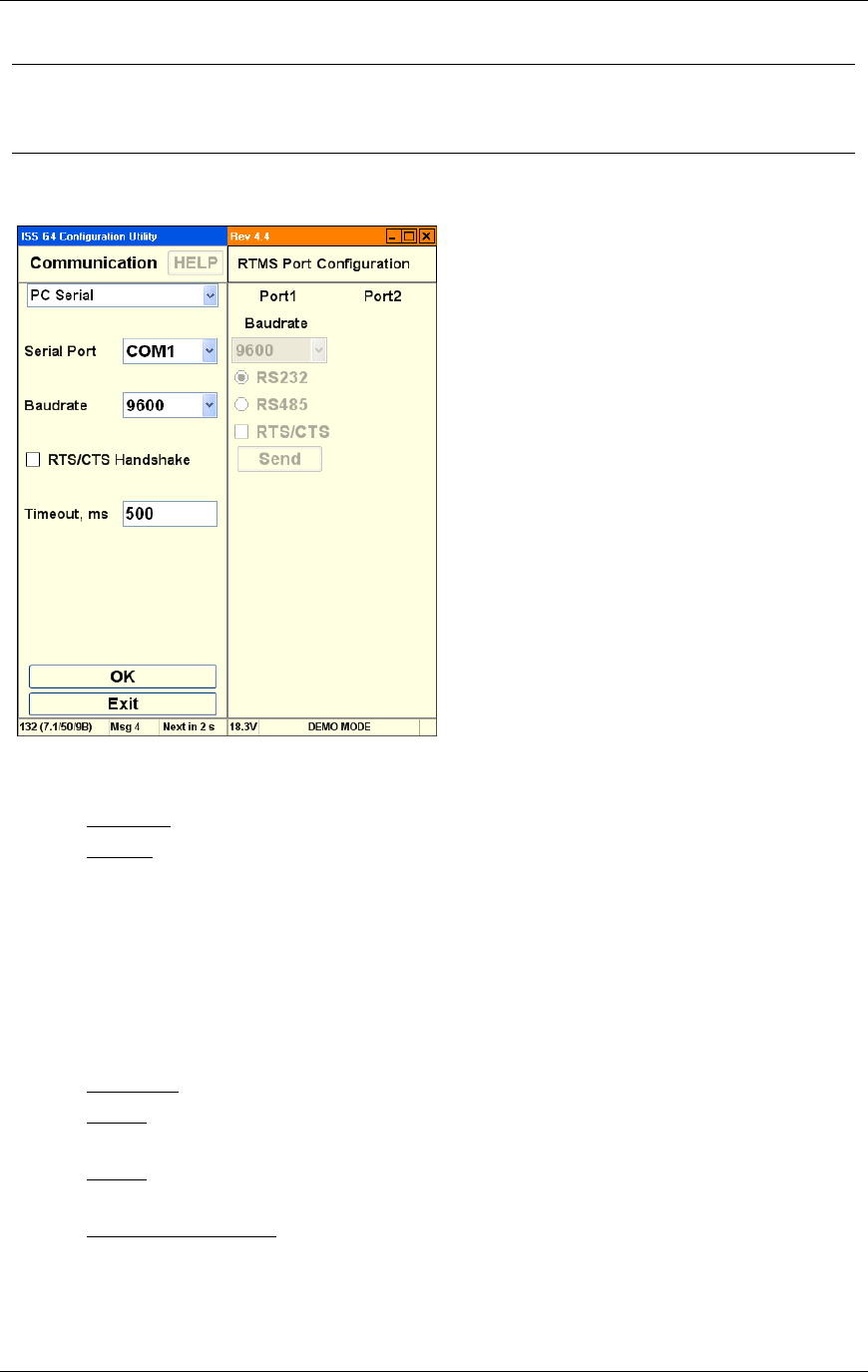
Chapter 3 G4 Software
RTMS® G4™ User Manual © 2010 Image Sensing Systems, Inc. 3-66
RTMS Communication Options
This screen allows you to configure communication protocols and specific parameters.
PC Serial Communication Options
Options are:
Mode. This drop-down allows to you to select the communication mode. Options are:
PC Serial. This option selects PC Serial communication.
TCP/IP. This option selects TCP/IP communication.
Baud Rate. This drop-down allows to you to select the data rate in bits per second.
Available baud rates differ by connection mode.
RTS/CTS. This enables handshake functionality between two modems.
Timeout, ms. This option allows you to specify the timeout period. If communication is
not established during this timeout period, the software returns to this screen and allows
you to try again.
Port 1. Allows you to specify communication parameters for Port 1.
Baud Rate. This drop-down allows to you to select the data rate in bits per second.
RS232. Allows you to specify the type of cable connection between the computer and
the RTMS sensor.
RS485. Allows you to specify the type of cable connection between the computer and
the RTMS sensor.
RTS/CTS Handshake. This uses handshake functionality between the PC and RTMS.
Send. Sends the communication parameters to the RTMS sensor.
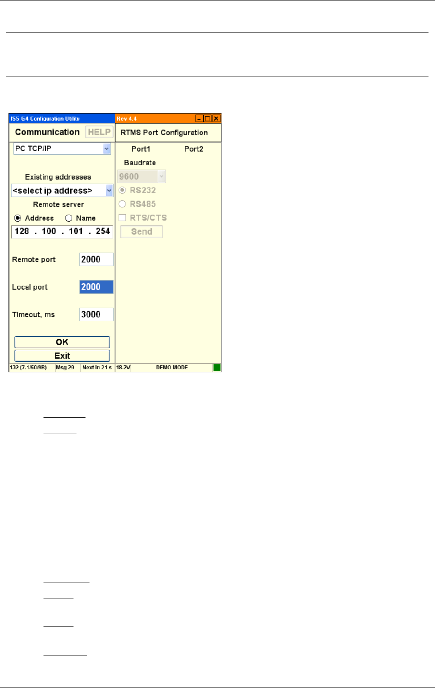
Chapter 3 G4 Software
RTMS® G4™ User Manual © 2010 Image Sensing Systems, Inc. 3-67
RTMS Communication Options…
This screen allows you to configure communication protocols and specific parameters.
PC TCP/IP Communication Options
Options are:
Mode. This drop-down allows to you to select the communication mode. Options are:
PC Serial. This option selects PC Serial communication.
TCP/IP. This option selects TCP/IP communication.
Existing Addresses. Provides a list of previous IP addresses.
Remote Server. Allows you to specify the name of the remote server by IP address or
name.
Remote Port. Allows you to specify the address of the remote port.
Local Port. Allows you to specify the address of the local port.
Timeout, ms. This option allows you to specify the timeout period. If communication is
not established during this timeout period, the software returns to this screen and allows
you to try again.
Port 1. Allows you to specify communication parameters for Port 1.
Baud Rate. This drop-down allows to you to select the baud rate in bits per second.
RS232. Allows you to specify the type of cable connection between the computer and
the RTMS sensor.
RS485. Allows you to specify the type of cable connection between the computer and
the RTMS sensor.
RTS/CTS. This enables handshake functionality between two modems.
Send. Sends the communication parameters to the RTMS sensor.

Chapter 3 G4 Software
RTMS® G4™ User Manual © 2010 Image Sensing Systems, Inc. 3-68
TCP/IP. Indicates that TCP/IP communication is selected.
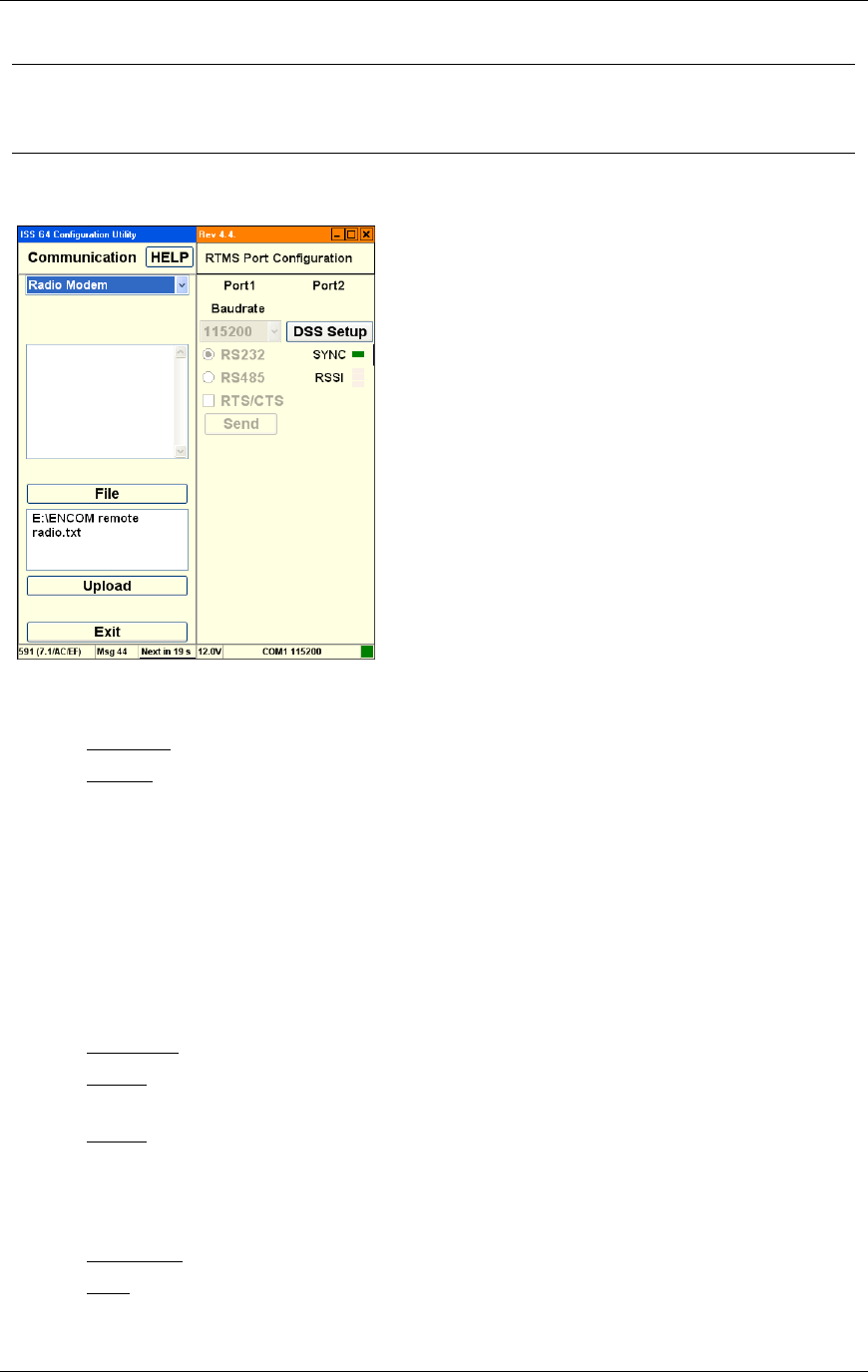
Chapter 3 G4 Software
RTMS® G4™ User Manual © 2010 Image Sensing Systems, Inc. 3-69
RTMS Communication Options…
This screen allows you to configure communication protocols and specific parameters.
Radio Modem Communication Options
Options are:
Mode. This drop-down allows to you to select the communication mode. Options are:
PC Serial. This option selects PC Serial communication.
TCP/IP. This option selects TCP/IP communication.
Window. Displays status messages during configuration. (For example: you might see
configuration instructions listed here as the instructions are sent to the mode. Success and
failure messages are displayed here.)
File. This option specifies an ASCII file containing modem instructions.
Window. Displays the filename currently used to configure the modem.
Upload. Sends the ASCII file instructions to the modem.
Exit. Returns to the previous screen.
Port 1. Allows you to specify communication parameters for Port 1.
Baud Rate. This drop-down allows to you to select the baud rate in Bits Per Second.
RS232. Allows you to specify the type of cable connection between the computer and
the RTMS sensor.
RS485. Allows you to specify the type of cable connection between the computer and
the RTMS sensor.
RTS/CTS. This enables handshake functionality between two modems.
Port 2. Allows you to specify communication parameters for Port 2.
DSS Setup. Allows you configure DSS radio communications.
Sync. A green light appears when WinRTMS is connected to the sensor via a radio
link.

Chapter 3 G4 Software
RTMS® G4™ User Manual © 2010 Image Sensing Systems, Inc. 3-70
RSSI. 1-3 bars indicate radio signal strength.
Send. Sends the communication parameters to the RTMS sensor.
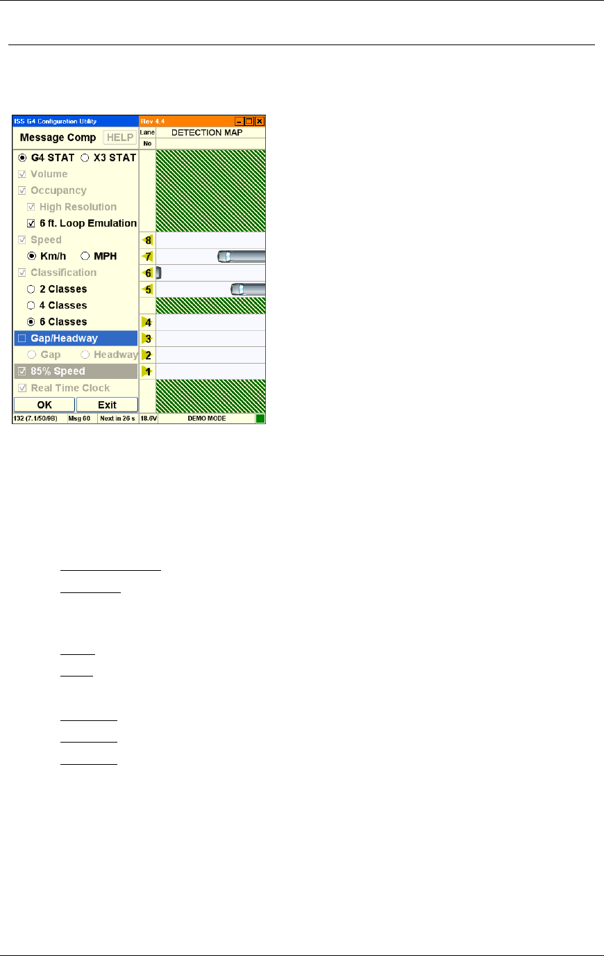
Chapter 3 G4 Software
RTMS® G4™ User Manual © 2010 Image Sensing Systems, Inc. 3-71
RTMS Message Composition Options
The Message Composition governs the content and format of each statistical message.
Options are:
G4 STAT. Transmit the data using the G4 protocol.
X3 STAT. Transmit the data using the X3 protocol.
Volume. The total number of vehicles in each message period.
Occupancy. The percentage of time a lane is occupied by a vehicle during the message
period.
High Resolution. Uses decimal place in the output results.
6 ft. Loop. Adds the loop length to the vehicle length for occupancy calculation.
Speed. Average vehicle speed during the message period. (X3 Stat mode only transmits
data in kilometers per hour.)
Km/h. Transmits speed data in kilometers per hour.
MPH. Transmits speed data in miles per hour.
Classification. The class lengths are set in Classification Options.
2 Classes. Determines how many classes to display in the Classification Options.
4 Classes. Determines how many classes to display in the Classification Options.
6 Classes. Determines how many classes to display in the Classification Options.
Gap Time Interval. Gap Time Interval is the average time between vehicles during a
Message Period.
Real Time Clock. Specifies that the software uses the RTMS internal clock for the real-
time clock when this option is selected.
Exit. Returns to the main screen.
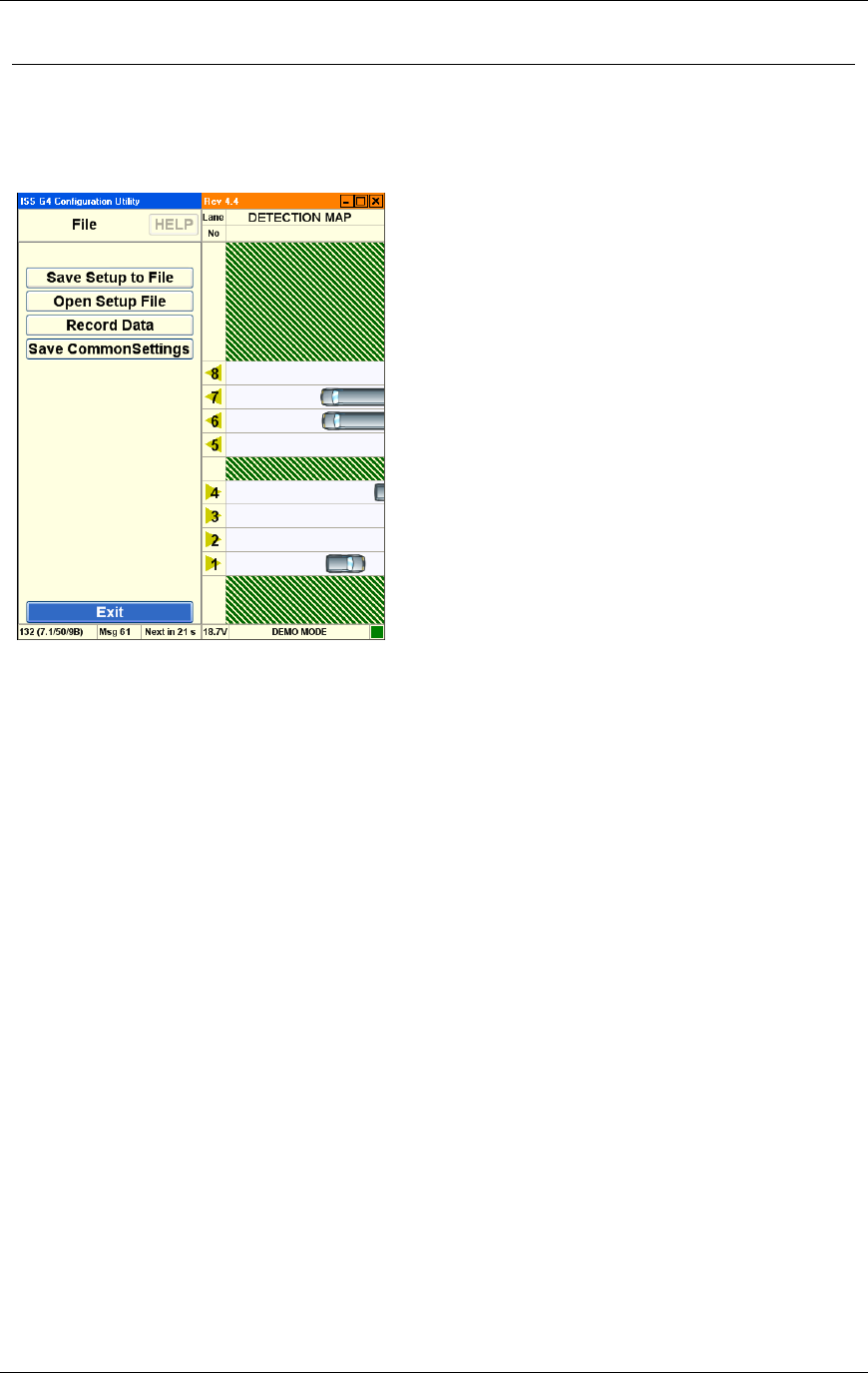
Chapter 3 G4 Software
RTMS® G4™ User Manual © 2010 Image Sensing Systems, Inc. 3-72
RTMS File Options
The Message Composition allows you to open configuration files, configure, save, and batch
apply your RTMS setup data, including statistical data to more than one sensor.
Options are:
Save Setup To File. This option saves the current configuration to a file on the hard disk.
Open Setup File. This option loads a configuration file from the hard disk.
Record Data. This option records RTMS statistical data to a file on the PC's hard disk.
See How to Record Data.
Save Common Settings. Save all the common configuration settings from your current
RTMS setup to the WinRTMS utility. These settings are applied to other RTMS sensors in
a single batch.
Exit. Returns to the previous screen.
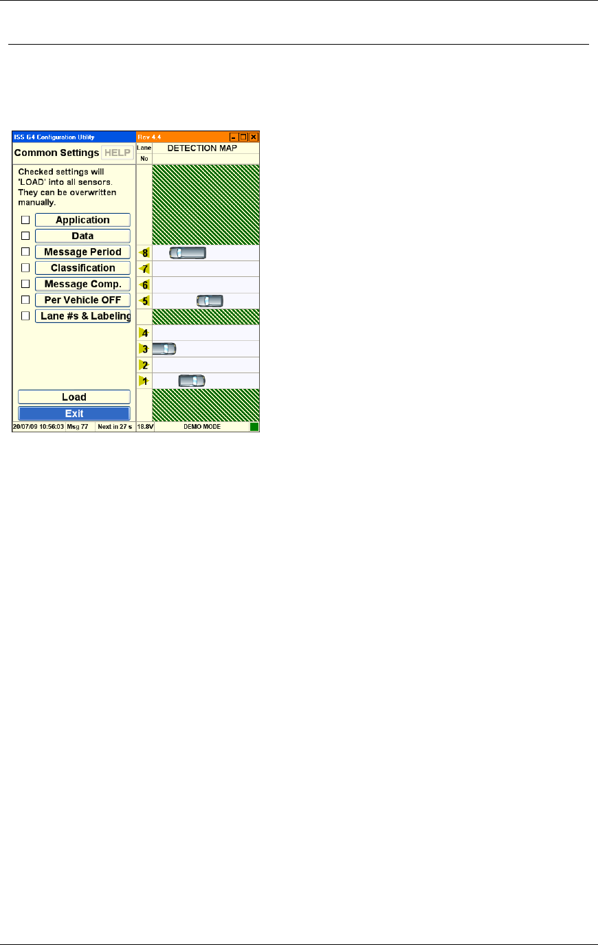
Chapter 3 G4 Software
RTMS® G4™ User Manual © 2010 Image Sensing Systems, Inc. 3-73
RTMS Common Settings
The WinRTMS common settings screen displays options that allow you to specify the basic
parameters for an entire group of sensors. See also, How to Configure Common Settings.
Options are:
Application. Select this option to use common Application settings for a group of RTMS
sensors.
Data. Select this option to use common Data settings for a group of RTMS sensors.
Message Period. Select this option to use common Message Period settings for a group of
RTMS sensors.
Classification. Select this option to use common Classification settings for a group of
RTMS sensors.
Message Comp. Select this option to use common Message Composition settings for a
group of RTMS sensors.
Per Vehicle Off. Select this option to use common Per Vehicle settings for a group of
RTMS sensors.
Lanes Labeling. Select this option to use common Lane Numbering and Labeling
settings for a group of RTMS sensors.
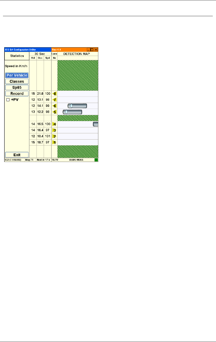
Chapter 3 G4 Software
RTMS® G4™ User Manual © 2010 Image Sensing Systems, Inc. 3-74
RTMS Statistics
The WinRTMS statistics screen displays traffic count information. Statistics are displayed for
Volume, Occupancy and Average Speed per lane, over the message period as shown.
Options are:
Per Vehicle. Provides individual vehicle information for each vehicle as the vehicles are
detected.
Classes. Displays the number of vehicles from each class that are detected during the
message period.
Sp85. Displays the 85th percentile speed for the most recent message period.
Record. Records a stream of human-readable ASCII from the RTMS sensor. This data is
typically used for troubleshooting.
Exit. Returns to the main screen.
Message Period (30 seconds in this example). Displays in seconds the message period.
Vol. Displays the total number of vehicles per lane.
Occ. % of lane occupancy for the message period.
Spd. Displays the average speed of traffic in the lane in km/h or MPH.
Lane No. Displays the lane number.
Detection Map. Displays a real-time visualization of traffic.
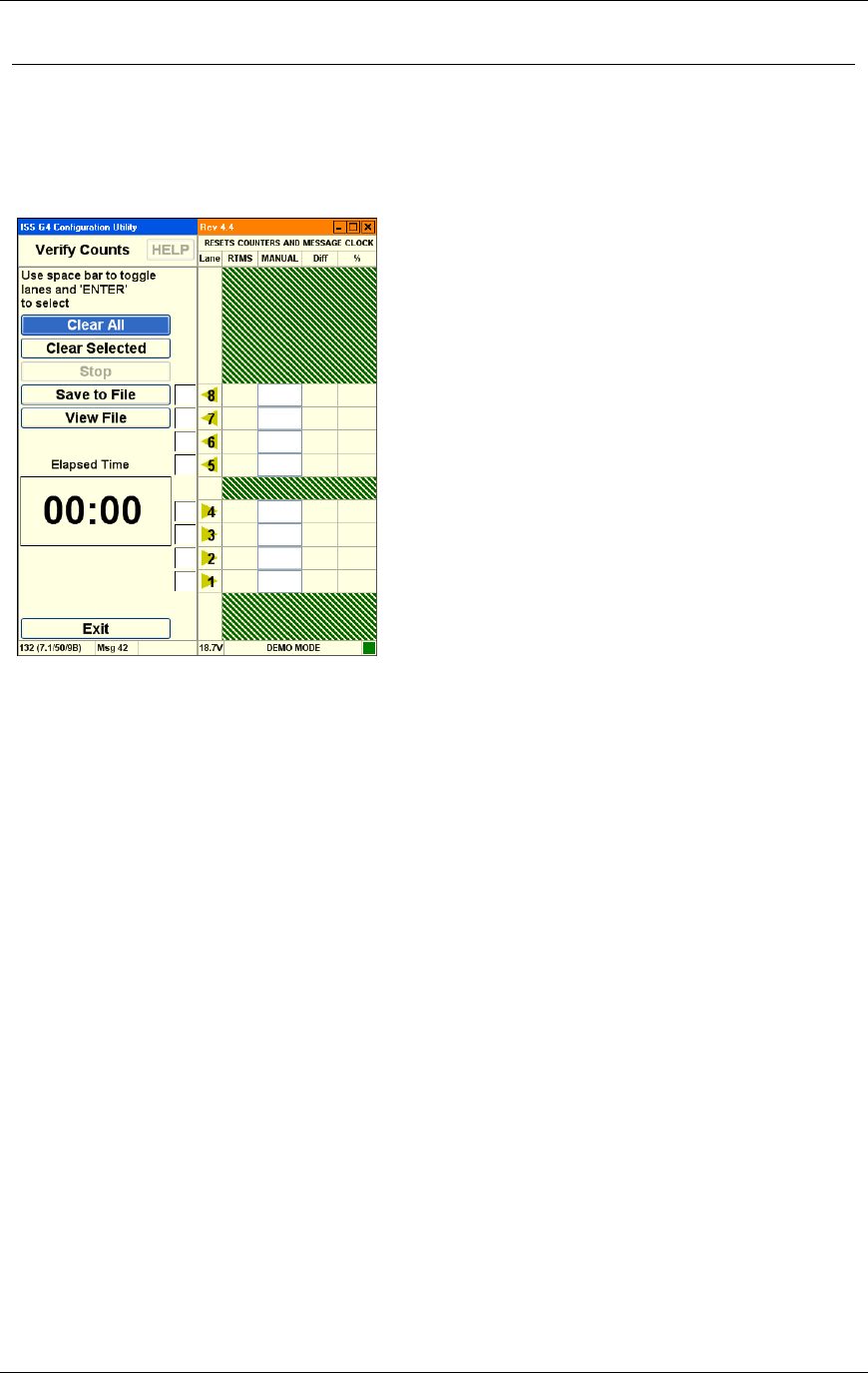
Chapter 3 G4 Software
RTMS® G4™ User Manual © 2010 Image Sensing Systems, Inc. 3-75
RTMS Verify Counts
The verification of a good zone setup is an essential part of the installation. In it we compare
RTMS volume measurements over a period of time with a manual (visual) count for the same
interval. Use of a hand-held tally counter is recommended.
Options are:
Clear All. This option clears the current values from all the traffic lanes.
Clear Selected. This option clears the current values from the selected traffic lanes.
Stop. This option terminates the counting process.
Save To File. This option allows you to save a count file to the hard disk.
View File. This option allows you to load a count file from the hard disk for review.
Elapsed Time. This option displays the amount of time since count verification started.
Exit. Returns to the main screen.
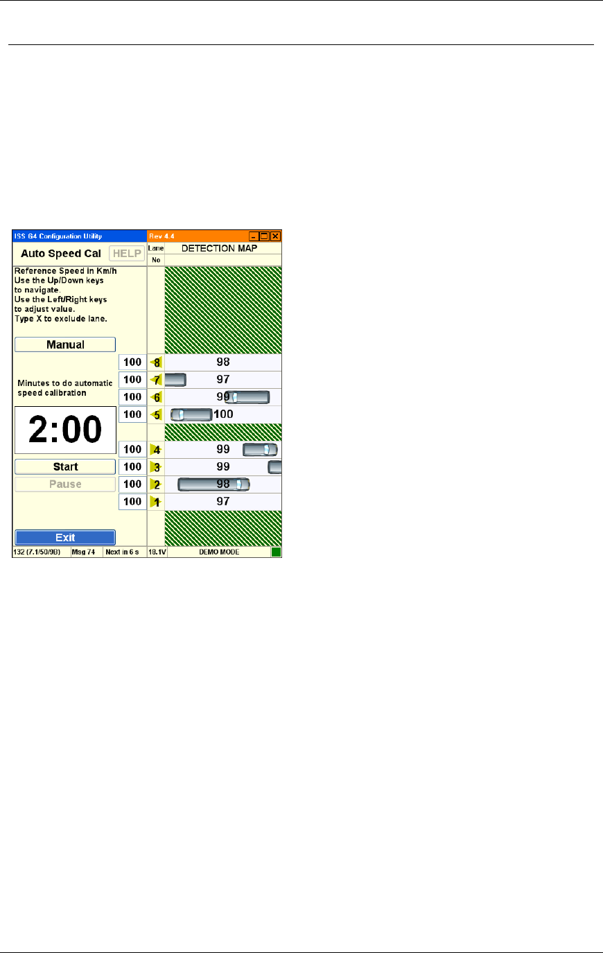
Chapter 3 G4 Software
RTMS® G4™ User Manual © 2010 Image Sensing Systems, Inc. 3-76
RTMS Automatic Speed Calibration
The speed calibration process sets the internal speed coefficients used to calculate the average
speed of traffic in each zone. The calibration procedure used depends on traffic conditions.
Note
When setting up relocated units at their new locations, all
speed coefficients should be first reset to their default values
using the Manual Speed Calibration window.
Options are:
Manual. Displays manual calibration options.
Start. Starts the calibration process.
Pause. Pauses the calibration process.
Exit. Returns to the main screen.
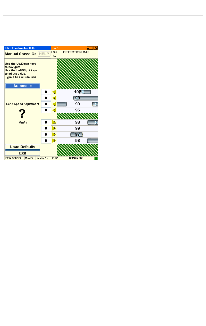
Chapter 3 G4 Software
RTMS® G4™ User Manual © 2010 Image Sensing Systems, Inc. 3-77
RTMS Manual Speed Calibration
The speed calibration process sets the internal speed coefficients used to calculate the average
speed of traffic in each zone. The calibration procedure used depends on traffic conditions.
Options are:
Automatic. Displays automatic calibration options.
Load Defaults. Loads the factory default coefficients.
Exit. Returns to the main screen.
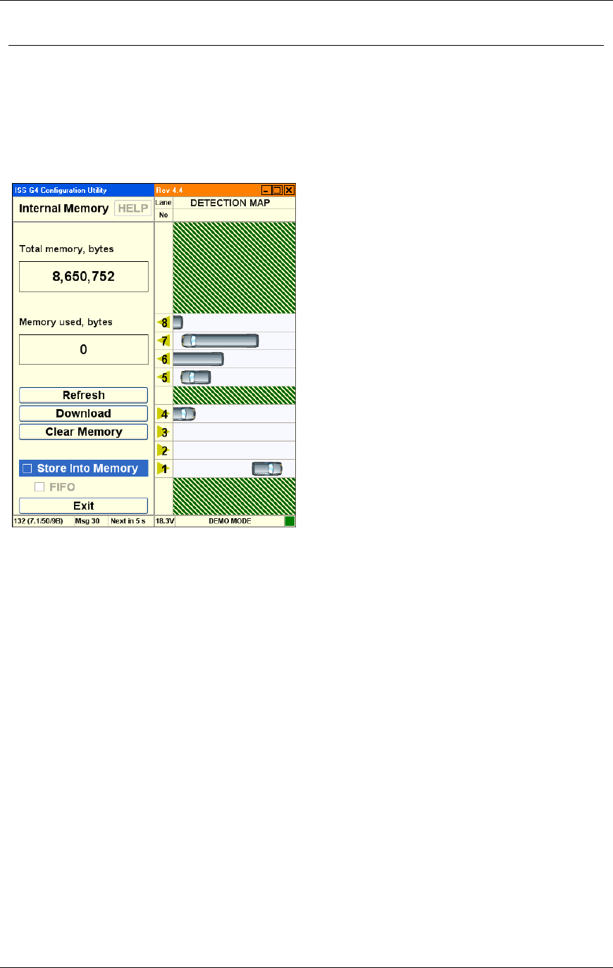
Chapter 3 G4 Software
RTMS® G4™ User Manual © 2010 Image Sensing Systems, Inc. 3-78
RTMS Internal Memory
The RTMS G4 includes internal memory. Please note:
Uncheck the Store Into Memory option prior to Downloading large volumes of data.
Download at the highest connection speed available when directly connected to the RTMS
sensor. A full memory will take just over 12 minutes to download at 115200 bps.
Options are:
Refresh. Updates the Memory Used parameter. Verifies data is being stored.
Download. Downloads the internal memory from the RTMS to the software.
Clear Memory. Clears the memory on the RTMS sensor.
Store Into Memory. This enables storage of RTMS data in the RTMS sensor's onboard
memory.
FIFO. (First In, First Out.) When memory is full, selecting this option instructs the RTMS
to overwrite the earliest stored message.
Exit. Returns to the main screen and saves changes. Activation of memory automatically
selects Real Time Clock in message composition for X3STAT.
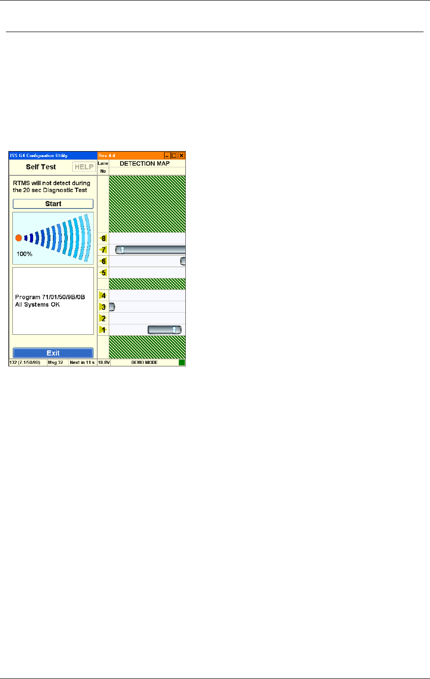
Chapter 3 G4 Software
RTMS® G4™ User Manual © 2010 Image Sensing Systems, Inc. 3-79
RTMS Self Test
The RTMS provides a diagnostic test of its internal functions. The test checks internal
functions and locates hardware faults. Please note:
The All System OK message is displayed on the screen if no faults are found.
The Self-Test will also close the (Optional) zone contacts for one second each in sequence.
Operation of the contacts can then be verified using the controller display, ohm-meter or
any other suitable device showing continuity.
The following is a list of Self-Test messages describing a fault:
Power supply fault.
Power supply fault.
Modulator signal fault.
Microwave module fault.
Modulator memory fault.
Program memory fault.
DSP fault.
Gain too low or ADC fault.
Logic failure.
No signal.
Saturation signal level.

RTMS® G4™ User Manual © 2010 Image Sensing Systems, Inc. A-1

AT Command Reference Appendix A
A-2 © 2010 Image Sensing Systems, Inc. RTMS® G4™ User Manual