Iolan Systems LA-WIWPROXKEYM Security Badge Reader User Manual ISIBR
Iolan Systems Inc. Security Badge Reader ISIBR
UserManual.wiki
>
Iolan Systems
>
LA-WIWPROXKEYM User Manual
>
ISI Technical Brochure
Contents
1.
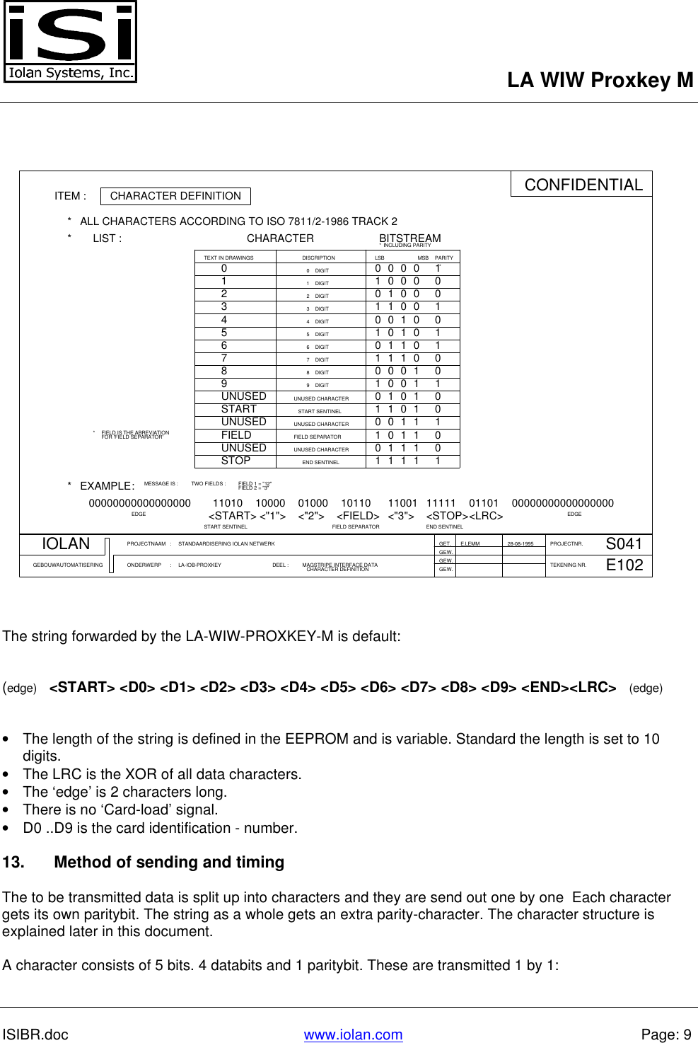
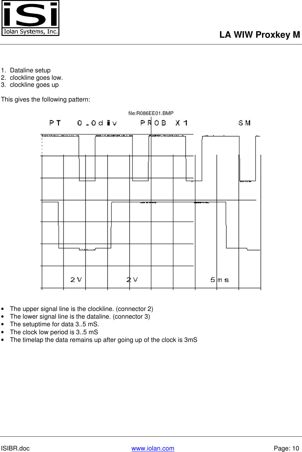
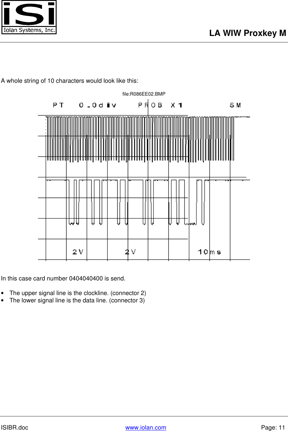
ISI Technical Brochure
2.
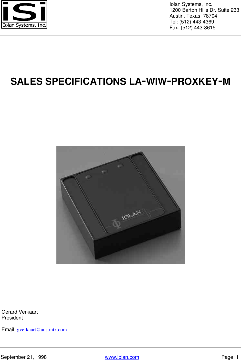
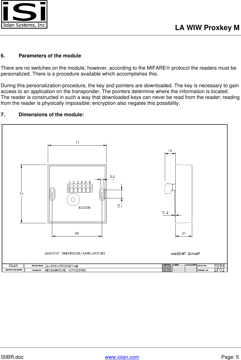
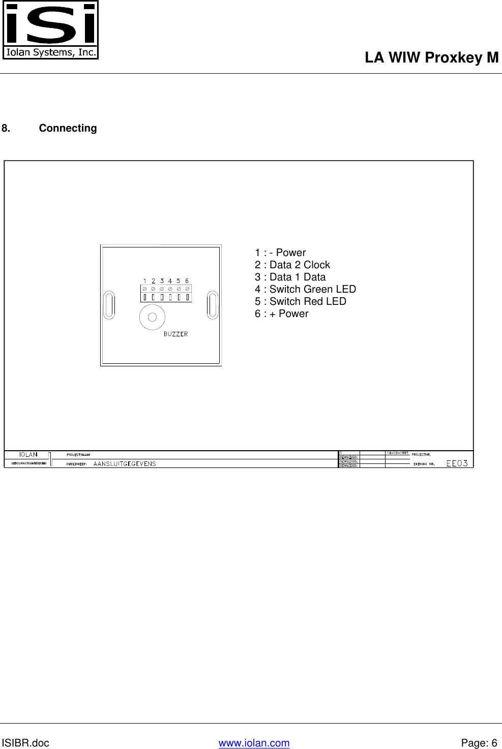
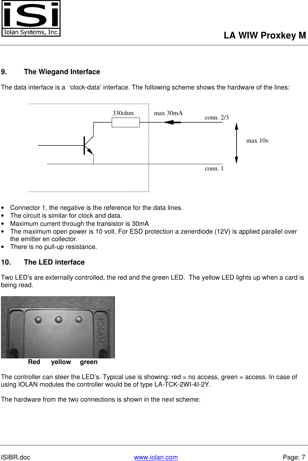
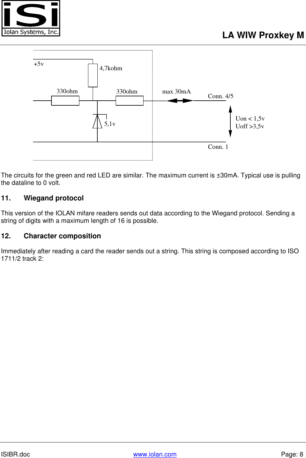
Badge Reader info
ISI Technical Brochure
Navigation menu
Upload a User Manual
Namespaces
Wiki Guide
HTML
PDF
Info
Views
User Manual
Discussion / Help
Navigation