Iridium Satellite 9603N Short Burst Data Transceiver User Manual Iridium 9602 9602N SBD Transceiver Developers Guide V1 2 DRAFT2
Iridium Satellite LLC Short Burst Data Transceiver Iridium 9602 9602N SBD Transceiver Developers Guide V1 2 DRAFT2
Contents
- 1. Developers guide
- 2. Iridium 9602_9602N SBD Transceiver Developers Guide V1.2 - DRAFT2
- 3. User Manual
- 4. User Manual II
- 5. User Manual III
Iridium 9602_9602N SBD Transceiver Developers Guide V1.2 - DRAFT2
![Iridium 9602/9602N SBD Transceiver Developer’s Guide Iridium Communications Inc. Proprietary & Confidential Information Iridium Communications Inc. 1750 Tysons Blvd, Suite 1400 McLean, VA 22102 www.iridium.com Toll Free: +1.866.947.4348 [US Only] International +1.480.752.5155 email: info@iridium.com](https://usermanual.wiki/Iridium-Satellite/9603N.Iridium-9602-9602N-SBD-Transceiver-Developers-Guide-V1-2-DRAFT2/User-Guide-2528726-Page-1.png)
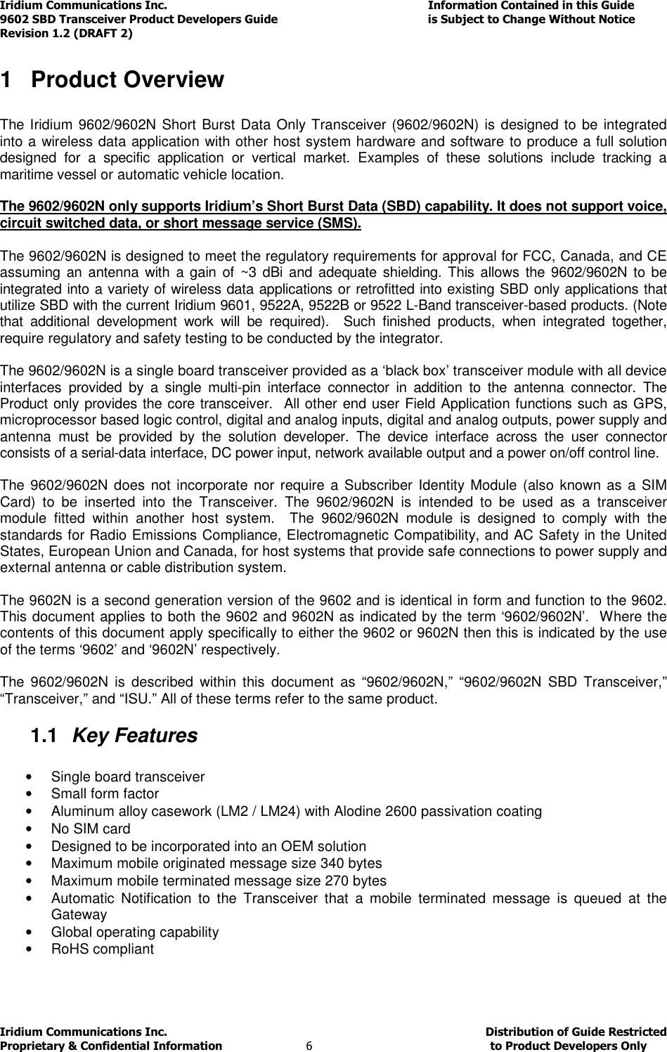
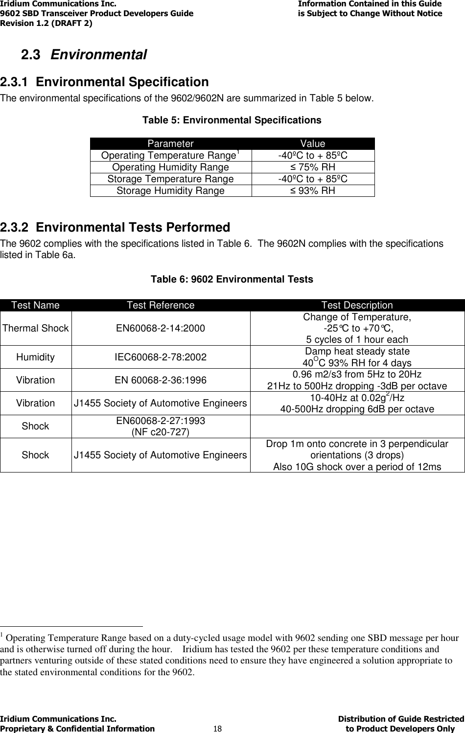
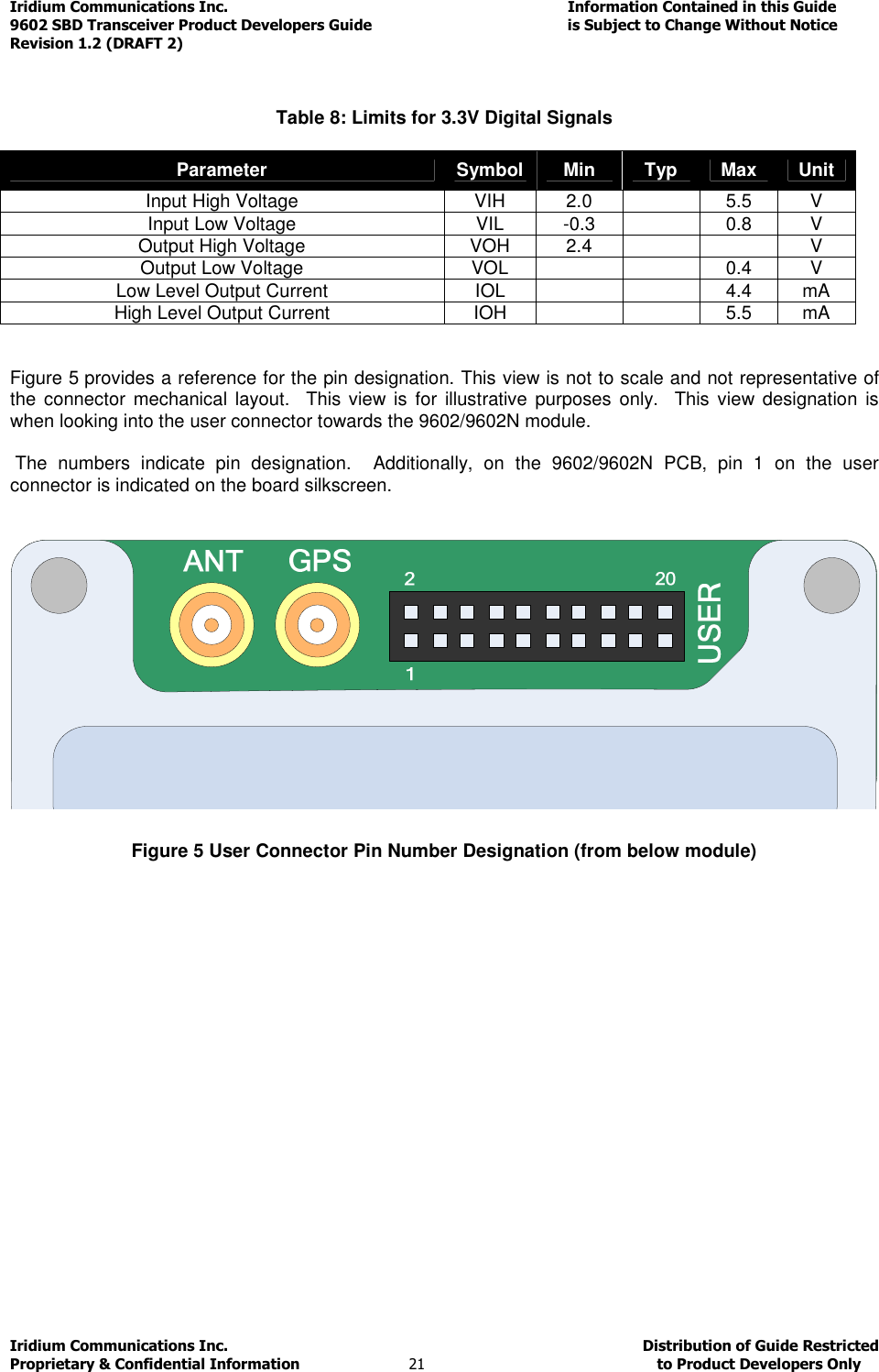
![Iridium Communications Inc. Information Contained in this Guide 9602 SBD Transceiver Product Developers Guide is Subject to Change Without Notice Revision 1.2 (DRAFT 2) Iridium Communications Inc. Distribution of Guide Restricted Proprietary & Confidential Information 25 to Product Developers Only Table 10 – Serial Interface Signals Signal Description RX Active high data output [The DTE receives the data from the 9602/9602N] TX Active high data input [Data is transmitted from the DTE to the 9602/9602N] GND 0V RTS Active low flow control input CTS Active low flow control output RTS and CTS are used together to implement hardware flow control when enabled with AT&K3 DTR Active low handshaking input AT&Dn controls how the 9602/9602N uses DTR: • If set to AT&D0, DTR is always ignored. • Otherwise DTR set to OFF places the data port into UART test mode after 10 seconds, or immediately on boot-up. A subsequent transition of DTR to ON returns the data port to DCE mode and resets it to its power-on state. • The UART test mode is provided for factory testing of the data port UART. An FA should never activate test mode; if it does, the 9602/9602N will stop responding to AT commands until the data port is returned to DCE mode. DSR Active low handshaking output The 9602/9602N drives DSR ON when the data port is in DCE mode, and OFF when the data port is in test mode. The DTE may use this signal as an indication that the 9602/9602N is powered up and ready to receive AT commands. RI Active low ring indicator output The 9602/9602N drives RI ON when it receives a Automatic Notification from the network that a Mobile Terminated SBD Message is queued at the Gateway, and drives RI OFF after 5 seconds or when the DTE initiates an SBD session, whichever occurs first. DCD Active low handshaking output DCD is driven OFF at all times. Note that the Ring Indicator (RI) pin is used by the 9602/9602N SBD Transceiver to indicate that a Mobile Terminated SBD (MT-SBD) message is queued at the Gateway. The Field Application can monitor this pin and use appropriate AT Commands to command the Transceiver to retrieve the MT-SBD message. The serial interface may be operated with a 3-wire connection, where only transmit, receive and ground signals are used. However the 9 wire interface offers better control and is the recommended implementation. Iridium is only able to provide limited 3-wire interface support. Due to the small code space and limited processing resources of the 9602/9602N the flow control is limited. When operating with a 3-wire connection, the following rules apply: • AT&Dn must be set to AT&D0 to ignore the DTR input • AT&Kn must be set to AT&K0 to disable RTS/CTS flow control • The other output signals may be connected, and operate as follows: • CTS driven ON (low) • DSR operates as normal • RI operates as normal • DCD driven ON (low)](https://usermanual.wiki/Iridium-Satellite/9603N.Iridium-9602-9602N-SBD-Transceiver-Developers-Guide-V1-2-DRAFT2/User-Guide-2528726-Page-25.png)
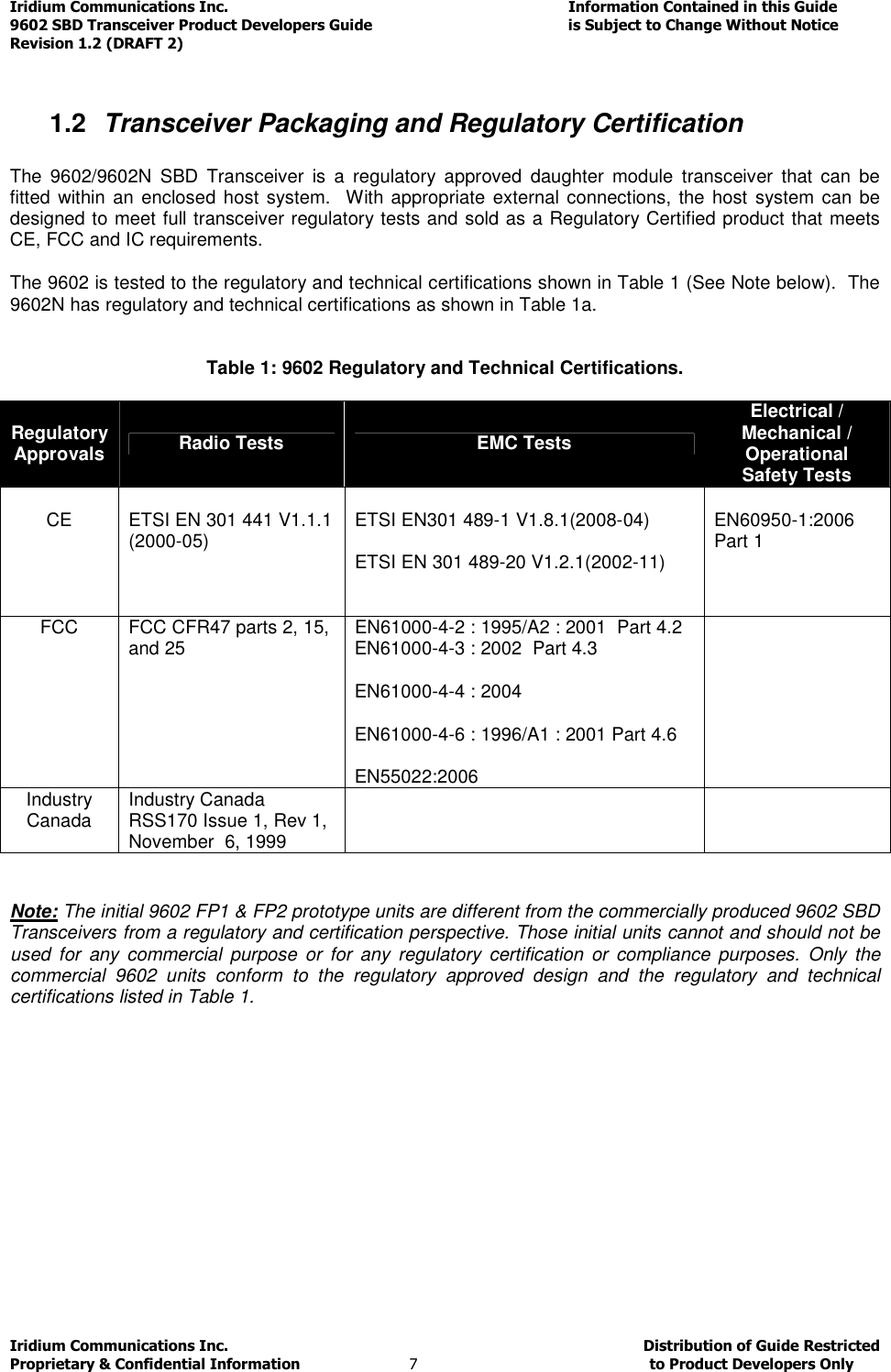
![Iridium Communications Inc. Information Contained in this Guide 9602 SBD Transceiver Product Developers Guide is Subject to Change Without Notice Revision 1.2 (DRAFT 2) Iridium Communications Inc. Distribution of Guide Restricted Proprietary & Confidential Information 26 to Product Developers Only Notes: 1. RTS/CTS flow control, when enabled, is only used when the data port is in SBD data mode. In AT command mode, RTS is ignored and CTS is driven ON (low). 2. If the DC input to the modem is to be disconnected, the developer will need to “tri-state” the serial interface to prevent a possible latch-up condition. 3.3.2 Configuration Settings The 9602/9602N allows the DTE to configure the data port communication parameters. The three configuration types are active, factory default, and stored. The active configuration is the set of parameters currently in use. They can be changed by the DTE individually via specific AT commands. The factory default configuration is stored in permanent memory. This configuration can be recalled at any time through use of the AT&Fn command. Two groups of settings, or “profiles”, can be stored as user-defined configurations. The DTE first creates desired active configurations and then writes them to memory using the AT&Wn command. These profiles can be designated to be loaded as the active configuration upon 9602/9602N power-up through use of the AT&Yn command. The 9602/9602N can be reset without loss of power to these profiles through use of the ATZn command. The configuration settings are stored in “S-register” locations and are detailed further in the “ISU AT Command Reference”. 3.3.3 Modes of Operation The serial interface is always in one of three modes: command mode, SBD data mode or SBD session mode. When the data port is in command mode, AT commands can be entered to control the 9602/9602N. In command mode, flow control has no effect, with the RTS input ignored and the CTS output driven ON (low). When in SBD data mode, the 9602/9602N is transferring binary or text SBD message data to or from the DTE. In SBD data mode: • All characters from the DTE not forming part of the message data are ignored (i.e. no AT commands may be entered) • No unsolicited result codes are issued. • RTS/CTS flow control, if enabled, is active. When RTS is OFF (high), the 9602/9602N suspends transfer of data to the DTE; when CTS is OFF (high), the 9602/9602N expects the DTE to suspend transfer of data to the 9602/9602N. When in SBD session mode, the 9602/9602N is attempting to conduct an SBD session with the network. In SBD session mode: • The DTE must wait for the +SBDI [X][A]session result code. • All characters from the DTE are ignored. • Unsolicited result codes are issued where those codes have been enabled. Transitions between the modes of operation are performed automatically by the 9602/9602N in response to the SBD AT Commands; the DTE has no other control over the mode.](https://usermanual.wiki/Iridium-Satellite/9603N.Iridium-9602-9602N-SBD-Transceiver-Developers-Guide-V1-2-DRAFT2/User-Guide-2528726-Page-26.png)
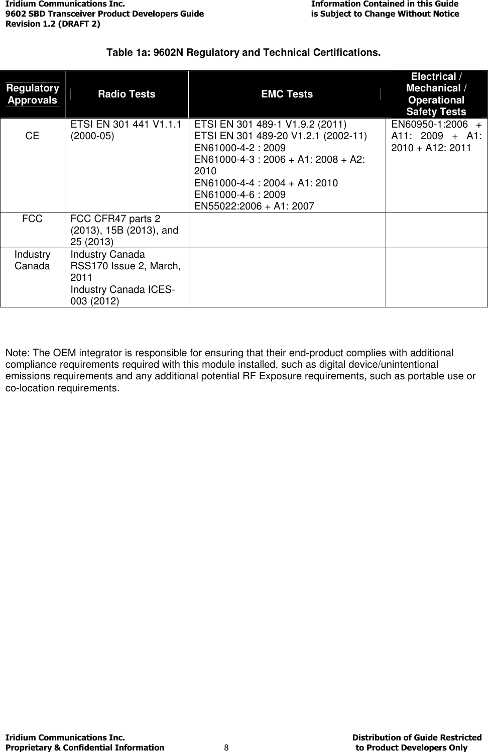
![Iridium Communications Inc. Information Contained in this Guide 9602 SBD Transceiver Product Developers Guide is Subject to Change Without Notice Revision 1.2 (DRAFT 2) Iridium Communications Inc. Distribution of Guide Restricted Proprietary & Confidential Information 27 to Product Developers Only 3.3.4 Serial port signal levels 3.3.4.1 Data Port Inputs The inputs on the 9602/9602N serial port (RTS, DTR and TXD) will operate correctly at 3.3V digital signal levels. RS-232 interface chips can be fitted to the host system motherboard if connection to an external RS232 link is required. Note that these may invert the digital logic level, so another inversion may be required. 3.3.4.2 Data Port Outputs The five outputs from the 9602/9602N serial port (DCD, DSR, CTS, RI and RXD) are all at 3.3V digital levels. 3.4 Hardware Failure Reporting If the 9602/9602N detects a hardware problem during initialisation, the 9602/9602N may be unable to function correctly. The 9602/9602N notifies the DTE of this situation by issuing an unsolicited result code at the end of initialisation: HARDWARE FAILURE: <subsys>,<error> where <subsys> identifies the software subsystem that detected the error, and <error> is the subsystem-specific error code. Any AT commands that cannot be handled in the failure condition will terminate with result code 4 (“ERROR”). 3.5 Network Available Output This is a digital output that can be used by an application to know when the transceiver has visibility to the satellite network. This is useful in applications where the transceiver may move around terrain that reduces the amount of time that clear line of sight to the satellite constellation is available. The Product Developer can use this output to preserve battery life by reducing the number of attempted transmissions by including this logic output in the application decision logic. Network Available means only that the 9602/9602N can successfully receive the Ring Channel, or, put more simply, it can see an Iridium satellite. Network Available is not a guarantee that a message can be successfully sent. The Network Available state is evaluated every time the Ring Channel is received or missed. If the Ring Channel is visible, then that is typically every 4 seconds. If the Ring Channel is not currently visible, then the update period can be as long as 2 minutes, depending on how long the lack of satellite visibility existed. This is because the 9602/9602N attempts to conserve power by increasing the ring search interval while the satellites are not visible. Every time a ring search fails, the time to wait is increased and eventually limits at 120 seconds. If Network Available is currently off, the Field Application may still attempt an SBDI[X] session. This will force the 9602/9602N Transceiver to look for the Ring Channel immediately, and on finding it, to attempt to send the message. In this case Network Available will not come on immediately. The Network Available does not turn on while in a +SBDI session. It will however turn on 4 seconds later assuming that the Ring Channel is present. After the SBD session completes, the 9602/9602N performs a new Ring Channel search sequence, at the end of which Network Available gets turned on. That can take between 4 and 12 seconds.](https://usermanual.wiki/Iridium-Satellite/9603N.Iridium-9602-9602N-SBD-Transceiver-Developers-Guide-V1-2-DRAFT2/User-Guide-2528726-Page-27.png)