Itron C3A-1L ELECTRICITY METER TRANSMITTER User Manual USERS MANUAL
Itron Electricity Metering, Inc. ELECTRICITY METER TRANSMITTER USERS MANUAL
Itron >
USERS MANUAL

5015 B.U. Bowman Drive Buford, GA 30518 USA Voice: 770-831-8048 Fax: 770-831-8598
FCC Part 15.247
Transmitter Certification
Frequency Hopping Spread Spectrum Transmitter
Test Report
FCC ID: SK9C3A-1L
FCC Rule Part: 15.247
ACS Report Number: 06-0013-15C
Manufacturer: Itron Electricity Metering Inc.
Trade name: CENTRON® IMAGE
Model: C3A1L
Manual

CENTRON® Polyphase Meter
Technical Reference Guide
Effective Date: January 2006
DRAFT

ii CENTRON® Polyphase Meter Technical Reference Guide
Proprietary Rights Notice
This manual contains the trade secrets and confidential information of Itron, Inc., which are
not to be divulged to third parties and may not be reproduced or transmitted in whole or
part, in any form or by any means, electronic or mechanical for any purpose, without the
express written permission of Itron, Inc. All rights to designs or inventions disclosed herein,
including the right to manufacture, are reserved to Itron, Inc.
The information contained in this document is subject to change without notice. Itron, Inc.
reserves the right to change the product specifications at any time without incurring any
obligations.
Trademarks Used in This Manual
CENTRON is a registered trademark of Itron, Inc.
Windows is a trademark of Microsoft Corporation.
CENTRON® Polyphase Meter Technical Reference Guide
Stock Number: 100xxxGM-01
Itron, Inc.
Corporate Headquarters
2818 North Sullivan Road
Spokane, WA 99216
U.S.A.
Tel: (509) 924-9900
Fax: (509) 891-3355
Itron, Inc.
Oconee Electricity Metering
313-B North Highway 11
West Union, SC 29696
U.S.A.
Tel: (864) 638-8300
Fax: (864) 638-4950
www.itron.com Copyright © 2005-2006
Itron, Inc.
All rights reserved.

CENTRON® Polyphase Meter Technical Reference Guide iii
Compliance With FCC Regulations
FCC Part 15, Class B
This equipment has been tested and found to comply with the limits for a Class B digital
device, pursuant to Part 15 of the FCC rules. These rules are designed to provide reasonable
protection against harmful interference when the equipment is operated in a
residential/commercial environment. This equipment generates, uses, and can radiate radio
frequency energy and, if not installed and used in accordance with the instructions, may
cause harmful interference to radio communications. However, there is no guarantee that
interference will not occur in a particular installation. If this equipment does cause harmful
interference to radio or television reception, which can be determined by turning the
equipment off and on, the user is encouraged to try to correct the interference by one or
more of the following measures:
Re-orient or relocate the receiving antenna.
Increase the separation between the equipment and the receiver.
Connect the equipment into an outlet on a circuit different from that to which the
receiver is connected.
Consult the dealer or an experienced radio/TV technician for help. This device complies
with Part 15 of the FCC rules.
THIS DEVICE COMPLIES WITH PART 15 OF THE FCC RULES. OPERATION IS
SUBJECT TO THE FOLLOWING TWO CONDITIONS: (1) THIS DEVICE MAY NOT
CAUSE HARMFUL INTERFERENCE, AND (2) THIS DEVICE MUST ACCEPT ANY
INTERFERENCE RECEIVED, INCLUDING INTERFERENCE THAT MAY CAUSE
UNDESIRED OPERATION.
FCC Part 15, Subpart C
When equipped with a radio transmitter option, this equipment has been tested and found to
comply with the limits for an intentional radiator, pursuant to Part 15, Subpart C of the FCC
Rules. This equipment generates, uses, and can radiate radio frequency energy. If not
installed and used in accordance with the instructions, it may cause interference to radio
communications.
The limits are designed to provide reasonable protection against such interference in a
residential situation. However, there is no guarantee that interference will not occur in a
particular installation. If this equipment does cause interference to radio or television
reception. which can be determined by turning the equipment on and off, the user is
encouraged to try to correct the interference by one of more of the following measures:
Reorient or relocate the receiving antenna of the affected radio or television.
Increase the separation between the equipment and the affected receiver.
Connect the equipment and the affected receiver to power outlets on separate circuits.
Consult the dealer or an experienced radio/TV technician for help.
Changes or modifications not expressly approved by Itron, Inc. could void the user’s
authority to operate the equipment.

iv CENTRON® Polyphase Meter Technical Reference Guide
RF Exposure Information
This equipment complies with the FCC RF radiation requirements for uncontrolled
environments. To maintain compliance with these requirements, the antenna and any
radiating elements should be installed to ensure that a minimum separation distance of 20
cm is maintained from the general population.
Canadian Interference Causing Equipment Regulations
This Class B digital apparatus meets all requirements of the Canadian Interference Causing
Equipment Regulations. Operation is subject to the following two conditions: (1) this device
may not cause harmful interference, and (2) this device must accept any interference
received, including interference that may cause undesired operation.
Cet appareillage numérique de la classe B répond à toutes les exigences de l'interférence
Canadienne causant des règlements d'équipement. L'opération est sujette aux deux
conditions suivantes: (1) ce dispositif peut ne pas causer l'interférence nocive, et (2) ce
dispositif doit accepter n'importe quelle interférence reçue, y compris l'interférence qui peut
causer l'opération peu désirée.
Factory Repair of Meters
Itron recommends that all repairs be performed at the factory. Certain repairs may be
performed by the user; however, unauthorized repairs will void any existing warranty. All
surface mounted parts must be replaced by the factory.
Repair of Meters Under Warranty
If the meter is under warranty, then Itron, Inc. will repair the meter at no charge if the meter
has failed due to components or workmanship. A return authorization number must be
obtained before the equipment can be sent back to the factory. Contact your Itron Sales
Representative for assistance.
Repair of Meters Not Under Warranty
The same procedure as above applies. Itron will charge for the necessary repairs based on
the failure.
Service Return Address
Itron, Inc.
Customer Repair Department
313 North Highway 11 Dock C
West Union, SC 29696

CENTRON® Polyphase Meter Technical Reference Guide v
Recycling Information
The product you have purchased contains a battery (or batteries), circuit boards, and
switches. The batteries are recyclable. At the end of the meter’s useful life, under
various state and local laws, it may be illegal to dispose of certain components into the
municipal waste system. Check with your local solid waste officials for details about
recycling options or proper disposal.
Although polycarbonate is not a commonly recycled plastic, the recycling number for
the polycarbonate inner cover, outer cover, and base is seven (7).

CENTRON® Polyphase Meter Technical Reference Guide vii
Table of Contents
Proprietary Rights Notice .........................................................................................ii
Trademarks Used in This Manual ..................................................................................................ii
Compliance With FCC Regulations............................................................................................... iii
FCC Part 15, Class B.......................................................................................................... iii
FCC Part 15, Subpart C...................................................................................................... iii
RF Exposure Information....................................................................................................iv
Canadian Interference Causing Equipment Regulations....................................................iv
Factory Repair of Meters...............................................................................................................iv
Repair of Meters Under Warranty.......................................................................................iv
Repair of Meters Not Under Warranty ................................................................................iv
Service Return Address......................................................................................................iv
Recycling Information.....................................................................................................................v
Chapter 1 General Information................................................................................1
About This Manual .........................................................................................................................1
General Description........................................................................................................................2
Physical Description.......................................................................................................................2
Meter Base...........................................................................................................................2
Personality Modules.............................................................................................................3
Product Availability.........................................................................................................................4
Outputs.................................................................................................................................4
Display Functions ...........................................................................................................................4
Specifications .................................................................................................................................4
Electrical...............................................................................................................................4
Operating Environment........................................................................................................5
Characteristic Data ..............................................................................................................5
Technical Data.....................................................................................................................5
Dimensions ..........................................................................................................................6
Chapter 2 Installation...............................................................................................7
Inspection .......................................................................................................................................7
Storage...........................................................................................................................................7
Unpacking.......................................................................................................................................7
Selecting a Site ..............................................................................................................................7
Installing the Meter into Service .....................................................................................................8
Retrofitting with Personality Modules.............................................................................................8
Chapter 3 Operation: Base Metrology ..................................................................13
Metrology......................................................................................................................................13
Surge Protection...........................................................................................................................14
Sampling.......................................................................................................................................14
Voltage and Current Measurement..............................................................................................15
Chapter 4 Operation: CP1S Version .....................................................................17
Physical Description.....................................................................................................................18

Table of Contents
viii CENTRON® Polyphase Meter Technical Reference Guide
Registers ......................................................................................................................................18
Kilowatt Hours....................................................................................................................18
Resetting Values................................................................................................................19
LCD Display Function...................................................................................................................19
Non-Detented Register........................................................................................... 20
Detented Register................................................................................................... 20
Net Register............................................................................................................ 20
Segment Check ...................................................................................................... 21
Factory Programming Options................................................................................ 21
Testing, Troubleshooting and Maintenance.................................................................................22
Chapter 5 Operation: CP1SR Version...................................................................23
Standard Consumption Message (SCM) .....................................................................................24
Interval Data Message (IDM) .......................................................................................................24
Physical Description.....................................................................................................................25
Registers ......................................................................................................................................25
Display ...............................................................................................................................25
Electronic Detent................................................................................................................26
Net Metering ......................................................................................................................27
Resetting Values................................................................................................................27
Transmission Scheme..................................................................................................................27
FCC Regulations................................................................................................................28
Tamper Detection.........................................................................................................................28
Testing the CENTRON CP1SR Tamper Counter..............................................................28
SCM Testing........................................................................................................... 28
Retrofitting the CP1SR Personality Module .................................................................................29
Testing, Troubleshooting and Maintenance.................................................................................30
Chapter 6 Operation: CP1SD/T/L Version.............................................................31
Controls and Indicators ................................................................................................................31
Demand Reset Button........................................................................................................32
Infrared Test LED...............................................................................................................32
Liquid Crystal Display (LCD)..............................................................................................32
Power Flow............................................................................................................. 33
Load Emulator ........................................................................................................ 34
Power Circle Quadrants.......................................................................................... 36
Magnetic Switch.................................................................................................................36
Optical Port ........................................................................................................................36
Test Mode Button...............................................................................................................37
Factory Reset ...............................................................................................................................37
Application of Power and Power-up.............................................................................................37
Power Down Procedures..............................................................................................................38
Demand Meter ...................................................................................................................38
TOU/Load Profile Meters ...................................................................................................38
Cold Load Pickup...............................................................................................................38
Interval Make-up ................................................................................................................39
Operating Modes..........................................................................................................................39
Normal Mode .....................................................................................................................39
Test Mode ..........................................................................................................................39
Test Mode Timeout................................................................................................. 40
Test Mode Lockout ................................................................................................. 40
Display Modes..............................................................................................................................40

Table of Contents
CENTRON® Polyphase Meter Technical Reference Guide ix
Energy Data Display Items ................................................................................................41
Demand Data Display Items ..............................................................................................41
Instantaneous Data Display Items.....................................................................................42
Informational Data Display Items.......................................................................................42
Magnetic Switch.................................................................................................................44
Scroll Lock .........................................................................................................................44
Changing Display Modes...................................................................................................44
Mode Timeout....................................................................................................................44
Normal Display Mode.........................................................................................................44
Alternate Display Mode......................................................................................................45
Toolbox Display Mode .......................................................................................................45
Test Display Mode .............................................................................................................46
Test Alternate Display Mode..............................................................................................47
Diagnostic Displays............................................................................................................47
Registers ......................................................................................................................................47
Energy Registers ...............................................................................................................47
Demand Registers .............................................................................................................48
Instantaneous Registers ....................................................................................................49
Self Read and Snapshot Registers....................................................................................49
Information Registers.........................................................................................................49
Interrogation and Programming....................................................................................................49
Interrogation.......................................................................................................................49
Programming .....................................................................................................................50
Time-of-Use (TOU).......................................................................................................................50
TOU Schedules..................................................................................................................50
Calendar Schedule ................................................................................................. 50
Rates....................................................................................................................... 50
Daily Patterns ......................................................................................................... 51
Day Types............................................................................................................... 51
Seasonal Schedules............................................................................................... 51
TOU Registers ...................................................................................................................51
Current Season Registers ...................................................................................... 51
Last Season Registers............................................................................................ 51
TOU Operation...................................................................................................................51
Rate Annunciators and Active Rate Indicators....................................................... 52
Season Change...................................................................................................... 52
Battery Carryover.................................................................................................... 52
Load Profile ..................................................................................................................................53
Load Profile Specifications.................................................................................................53
Capacity.................................................................................................................. 53
Bit Resolution.......................................................................................................... 53
Interval Lengths ...................................................................................................... 54
Power Outage......................................................................................................... 54
Channel Configuration .......................................................................................................54
Pulse Constants.................................................................................................................54
Data Storage......................................................................................................................55
Recording Duration............................................................................................................56
Event Log .....................................................................................................................................56
Security Codes .............................................................................................................................58
Implementing Security Codes............................................................................................59
Clearing Security Codes ....................................................................................................59
Firmware Upgrades......................................................................................................................60
Installing D/T/L Register Firmware on the PC ...................................................................60
R300 Series..................................................................................................................................60
SiteScan On-Site Monitoring System...........................................................................................61

Table of Contents
x
CENTRON® Polyphase Meter Technical Reference Guide
SiteScan Meter Self-Diagnostic Checks............................................................................62
SiteScan Toolbox Mode.....................................................................................................62
SiteScan System and Installation Diagnostic Checks .......................................................66
SiteScan Diagnostic #1......................................................................................................72
Current Angle Tolerance......................................................................................... 72
Cross-Phase, Polarity, and Energy Flow Check .................................................... 72
SiteScan Diagnostic #2......................................................................................................74
Phase Voltage Deviation Check ............................................................................. 75
SiteScan Diagnostic #3......................................................................................................76
Inactive Phase Current Check................................................................................ 76
SiteScan Diagnostic #4......................................................................................................78
Low End Threshold Current.................................................................................... 78
Phase Angle Displacement Check ......................................................................... 78
SiteScan Diagnostic #5......................................................................................................80
Current Waveform Distortion Check....................................................................... 81
SiteScan Diagnostic #6......................................................................................................81
Diagnostic #6 Error Example.................................................................................. 81
Testing, Troubleshooting, and Maintenance................................................................................82
Visual Indicators.................................................................................................................82
Infrared Test LED ................................................................................................... 82
Annunciators......................................................................................................................82
Load Indication/Direction Annunciator.................................................................... 83
Phase-Voltage Indication Annunciators.................................................................. 83
Nominal Voltage Indication Annunciator................................................................. 84
Test Mode Annunciator........................................................................................... 84
Energy Testing...................................................................................................................84
Testing With the Infrared Test LED ........................................................................ 84
Testing Using the Load Indication Annunciator...................................................... 85
Testing Using the Energy/Time Method ................................................................. 85
Recommended Energy Testing Procedures......................................................................85
Test Description...................................................................................................... 85
Recommendations.................................................................................................. 86
Demand Testing.................................................................................................................87
Demand Test Method ............................................................................................. 88
Demand Calculations.............................................................................................. 89
Field Testing ......................................................................................................................90
Required Hardware................................................................................................. 90
Test Method Using Infrared Pulse Adapter ............................................................ 90
Test Method Using a Snap Switch Assembly......................................................... 90
Troubleshooting .................................................................................................................91
Fatal Errors ............................................................................................................. 91
Non-Fatal Errors ..................................................................................................... 92
Other Problems....................................................................................................... 95
Maintenance ......................................................................................................................97
Preventive Maintenance ......................................................................................... 97
Corrective Maintenance.......................................................................................... 97
Glossary of Terms...................................................................................................99
Index.......................................................................................................................101

CENTRON® Polyphase Meter Technical Reference Guide xi
Table of Figures
Figure 1: CENTRON Polyphase Meter Metrology .........................................................................3
Figure 2: CENTRON Personality Module Assembly......................................................................3
Figure 3: Dimensions .....................................................................................................................6
Figure 4: Removing the Board-to-Board Connector ......................................................................9
Figure 5: Circuit Board Notches...................................................................................................10
Figure 6: Board-to-Board Connector, Bottom ..............................................................................10
Figure 7: Board-to-Board Connector, Top ...................................................................................11
Figure 8: CENTRON Polyphase Metrology .................................................................................13
Figure 9: Sampled Waveform ......................................................................................................14
Figure 10: Voltage and Current Measurement.............................................................................15
Figure 11: CP1S LCD Personality Module...................................................................................17
Figure 12: ZRO-C2A Resetter Connected to the CENTRON ......................................................19
Figure 13: Non-Detented Register (kWhd + kWhr)......................................................................20
Figure 14: Delivered kWh with Detent Enabled (kWhd)...............................................................20
Figure 15: Net kWh (kWhd - kWhr)..............................................................................................20
Figure 16: Segment Check ..........................................................................................................21
Figure 17: CENTRON CP1SR Meter...........................................................................................23
Figure 18: CP1SR LCD................................................................................................................25
Figure 19: CENTRON-IDM High Power SCM/IDM Transmission Scheme .................................27
Figure 20: CP1SR FCC Label Location .......................................................................................29
Figure 21: CENTRON Polyphase Meter LCD..............................................................................32
Figure 22: Load Emulator Segment Progression for Delivered Power........................................34
Figure 23: Load Emulator Segment Progression for Received Power ........................................35
Figure 24: Power Circle Diagram.................................................................................................36
Figure 25: Toolbox Phase Notation for Form 9S and 16S CENTRON Polyphase Meters..........63
Figure 26: Plot of Toolbox Display Mode .....................................................................................64
Figure 27: Form 9S CENTRON Polyphase Meter 4-Wire Delta Phasor Diagram.......................68
Figure 28: Form 9S CENTRON Polyphase Meter 4-Wire Wye Phasor Diagram ........................69
Figure 29: Form 16S CENTRON Polyphase Meter 4-Wire Delta Phasor Diagram.....................70
Figure 30: Form 16S CENTRON Polyphase Meter 4-Wire Wye Phasor Diagram ......................71
Figure 31: Diagnostic #1 Error Diagram.......................................................................................74
Figure 32: Envelope Example......................................................................................................79
Figure 33: Phasor Diagram..........................................................................................................80
Figure 34: Load Emulator Segment Progression.........................................................................83
Figure 35: Test Connections ........................................................................................................88

CENTRON® Polyphase Meter Technical Reference Guide 1
CHAPTER 1
General Information
In This Chapter
About This Manual................................................................................................1
General Description...............................................................................................2
Physical Description..............................................................................................2
Product Availability...............................................................................................4
Display Functions..................................................................................................4
Specifications.........................................................................................................4
This technical reference guide explains the installation, operation, and maintenance of the
Itron CENTRON Polyphase meter family. Itron urges you to read the entire manual before
attempting installation, testing, operation, or maintenance of a meter. To operate the Itron
PC-PRO+ Advanced Programming Software and the PRO-READ handheld reader
programmer discussed in this manual, refer to their respective user manuals.
About This Manual
This manual contains the following information as listed in the chapter descriptions below:
General Information Provides a general description, operation, physical and
functional descriptions, and complete CENTRON
Polyphase meter specifications.
Installation Gives instructions for the proper handling and
installation.
Operation: CP1S Provides a physical description and operational
characteristics of the CP1S watthour (kWh) only meter.
Operation: CP1SR Provides a physical description and the operational
characteristics of the CP1SR R300 900 MHz radio
frequency personality module.
Operation: CP1SD, CP1ST,
and CP1SL Provides detailed information and theoretical operation
for Demand (CP1SD), Time-of-Use (CP1ST), and Load
Profile (CP1SL) versions. Gives step-by-step
procedures for accessing the three operational modes
and associated displays.
Testing, Troubleshooting,
and Maintenance Provides an explanation of the testing, troubleshooting,
and maintenance of the CENTRON Polyphase meter.
Specification Numbers and
Drawings Provides a reference to meter part numbers and shows
meter form drawings.

General Information
2 CENTRON® Polyphase Meter Technical Reference Guide
General Description
The CENTRON meter family is a solid-state, polyphase meter used for measuring electrical
energy consumption. The CENTRON incorporates a two-piece design combining a base
metrology with a variety of personality modules that snap on the standard meter base.
Utilizing the Hall Effect technology for accurate power measurement, the metrology portion
of the meter contains all measurement circuitry and calibration information, while the
personality modules contain the register functionality and communication mediums.
Each version of the meter is distinguished by the various personality modules that mount to
the standard meter metrology base. The personality modules available include the following
versions:
Energy only—CP1S (LCD)
Energy only with radio frequency AMR—CP1SR
Demand/TOU/LP—CP1SD/T/L
Demand/TOU/LP & RF—CP1SR2/R3
Need new picture
Physical Description
The CENTRON Polyphase meter features a common meter base to which various
personality modules are attached. The cover is polycarbonate.
Meter Base
The CENTRON Polyphase meter base contains all of the measurement circuitry and
calibration information on the metrology board.
The meter base assembly includes three current conductors, three flux-directing cores, three
Hall Effect devices, the metrology circuit board, and the ultrasonically welded module
support. The base also contains three metal oxide varistors (MOV), which are used to
protect the meter from line surges.
General Information
CENTRON® Polyphase Meter Technical Reference Guide 3
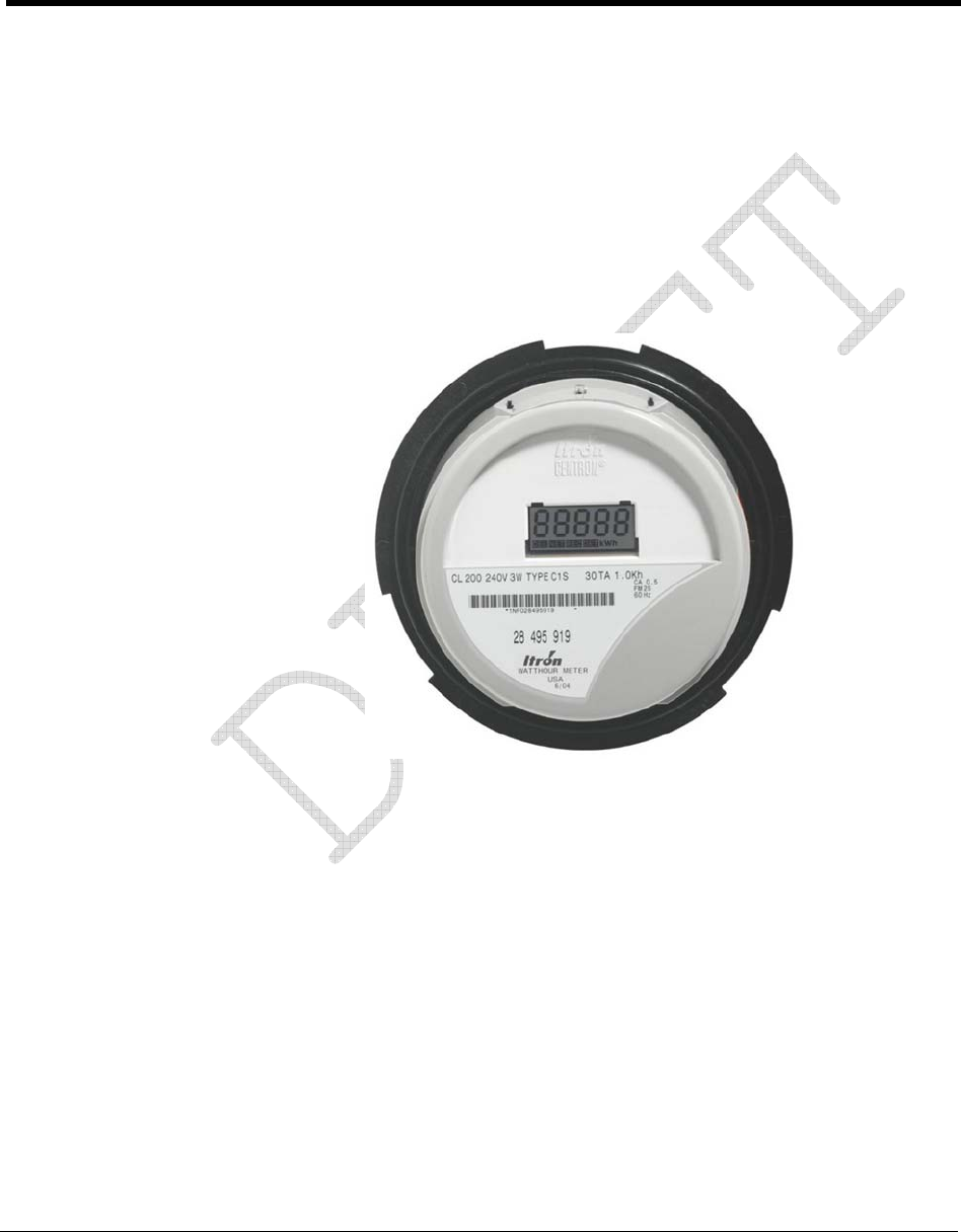
Meter bases are built specific to the metering form and are available in Form 9S CL20 and
Form 16S CL200 configurations. All meter forms are auto-voltage ranging from 120 to 480
volts. An example of the metrology is shown below.
Figure 1: CENTRON Polyphase Meter Metrology
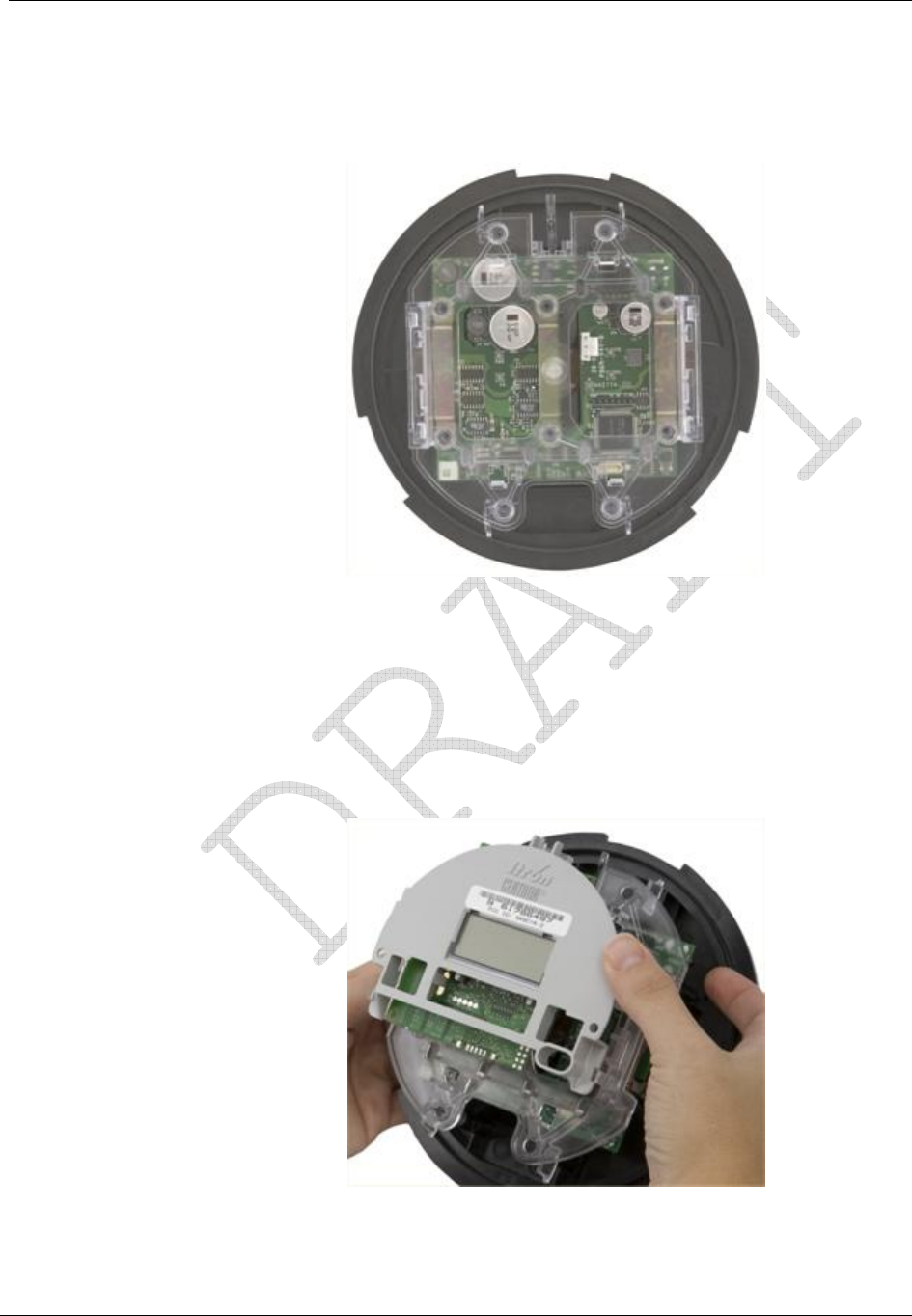
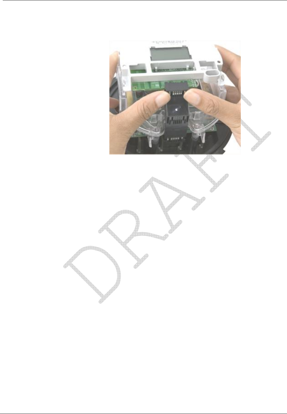
Personality Modules
All of the personality modules in the CENTRON Polyphase meter family snap into the
module holder located on the standard meter base as shown below. From the base
metrology, the energy data is transmitted to the personality modules, which contain the
meter display, communication mediums, and register functionality.
Figure 2: CENTRON Personality Module Assembly

General Information
4 CENTRON® Polyphase Meter Technical Reference Guide
Product Availability
The current offerings for the CENTRON are:
Metrology Class 20, 120-480V, Form 9S
Class 200, 120-480V, Form 16S
Personality Modules CP1S—LCD (5x1 or 4x10)
CP1SR—R300C (Radio Frequency)
CP1SD/T/L—Demand/TOU/LP
CP1SR2/R3—R300CD/R300CD3
Outputs
The CP1SD, CP1ST, and CP1SL personality modules are available input/output-ready
(I/O-ready). These modules contain circuitry that allows future functionality expansion
through I/O modules.
Display Functions
The CP1S and CP1SR modules can display kWh readings in either a 5x1 or 4x10
configuration.
Specifications
Electrical
Voltage Rating 120 - 480V
Operating
Voltage ± 20% (60 Hz); ± 10% (50 Hz)
Frequency 60 Hz, 50 Hz
Operating Range ± 3 Hz

General Information
CENTRON® Polyphase Meter Technical Reference Guide 5
Operating Environment
Temperature -40°C to +85°C
Humidity 0% to 95% non-condensing
Accuracy ± 0.2% @ unity power factor
± 0.3% @ 50% power factor
Transient/Surge
Suppression ANSI C37.90.1 - 1989
IEC 61000-4-4
ANSI C62.45 - 1992
Characteristic Data
Temperature Rise Meets ANSI C12.1 Section 4.7.2.9
Technical Data
Meets applicable standards:
ANSI C12.1 - 2001
ANSI C12.16 (Solid State Meters)
ANSI C12.18 (Optical Communications Protocol)
ANSI C12.19 - 2001
ANSI C12.20 (Class 0.2) - 2002
IEC 61000-4-4
IEC 61000-4-2
General Information
6 CENTRON® Polyphase Meter Technical Reference Guide
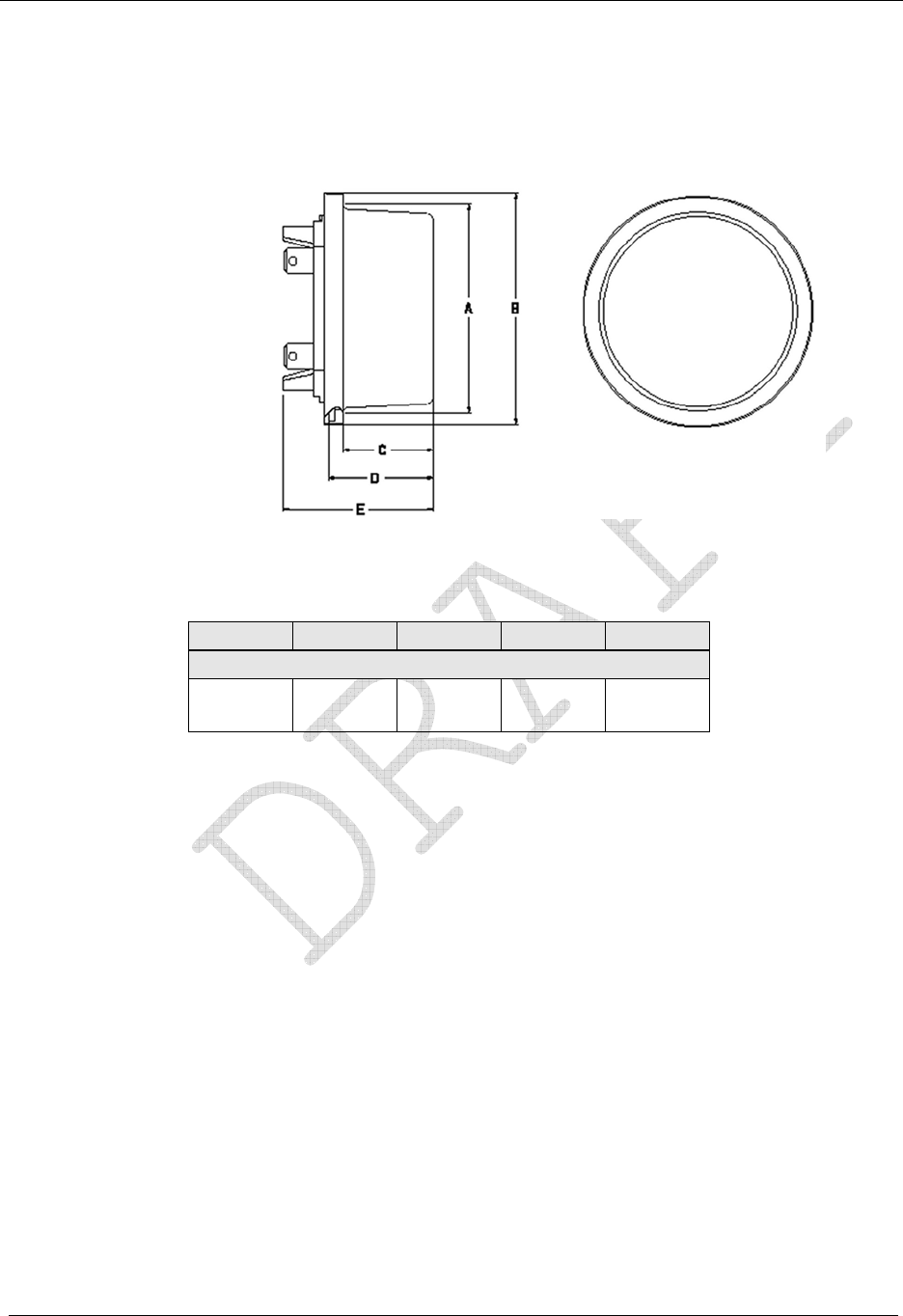
Dimensions
The following dimensional measurements are shown in inches and (centimeters).
Figure 3: Dimensions
A B C D E
Polycarbonate
6.29 (16.00) 6.95 (17.70) 2.70
(6.90) 3.16
(8.00) 4.53
(11.50)

CENTRON® Polyphase Meter Technical Reference Guide 7
CHAPTER 2
Installation
In This Chapter
Inspection ..............................................................................................................7
Storage...................................................................................................................7
Unpacking..............................................................................................................7
Selecting a Site ......................................................................................................7
Installing the Meter into Service............................................................................8
Retrofitting with Personality Modules...................................................................8
Inspection
Perform the following inspections when you receive the meter:
Inspect for obvious damage to the cover, base, and meter assembly.
Compare the meter and register nameplates to the record card and invoice. Verify the
type, class, voltage, form number, and other pertinent data.
Save the original packing materials.
Storage
Store the meter in a clean, dry (Relative Humidity < 50%) environment between -40° C to
+85° C (-40° F to +185° F). Avoid prolonged storage (more than one year) at temperatures
above +70° C(+158° F). Store the meter in the original packing material.
Unpacking
As with all precision electronic instruments, the meter should be handled with care in an
outdoor environment. Follow these precautions when handling the meter:
Avoid damaging the meter base, cover, reset mechanism (if supplied), and optical
connector (if supplied).
When handling personality modules, grip the circuit board by its edges. Do not touch
the liquid crystal display.
Selecting a Site
The meter is designed and manufactured to be installed in an outdoor environment, at
operating temperature ranges between -40° C and +85° C (-40° F to +185° F). Operation in
moderate temperatures increases reliability and product life.

Installation
8 CENTRON® Polyphase Meter Technical Reference Guide
Installing the Meter into Service
Install the meter base using standard meter installation practices.
The current and potential terminals extend as blades, or bayonets, from the back of the
meter. The meter is plugged into the socket so that the bayonets engage the main socket
jaws that connect to the service lines. Clamping pressure on the bayonets is provided by the
heavy spring pressure of the socket jaws. In some heavy-duty sockets, jaw clamping
pressure is provided by a handle or wrench.
On meters equipped with LCD displays, verify register operations by observing the display:
LCD displays the correct number of digits (4 or 5).
If the register only displays a Segment Test (all display items shown) and flashes
“norDisplay” or "3BReset", then the register has not been programmed.
Verify that no errors are displayed.
Retrofitting with Personality Modules
CENTRON meters can be upgraded to increase functionality by changing the Personality
Modules.
Do not power ON the meter without the inner cover in
place. Power the meter OFF before removing the inner
cover. Personality modules are sensitive to ESD
damage. Take appropriate grounding measures before
retrofitting!
To change or add a Personality Module:
1 Remove power from the meter.
2 Remove the outer cover.
3 Remove plastic inner cover by holding the meter with both hands and applying equal
pressure on either side of the three and nine-o’clock positions. The inner cover is held in
place by four plastic tabs on the meter base.
Installation
CENTRON® Polyphase Meter Technical Reference Guide 9
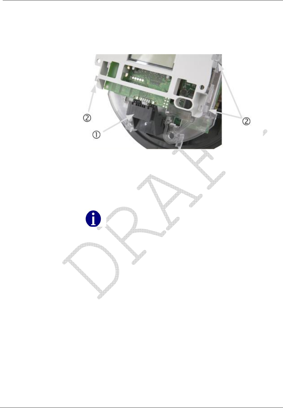
4 Remove the black board-to-board connector (1 in the figure below) between the
circuit board and the metrology board by pulling it by its middle while moving it side-
to-side. To maintain the integrity of the connector, only remove it when you are
upgrading the meter.
Figure 4: Removing the Board-to-Board Connector
5 Remove the register module, one side at a time, by pulling gently outward on the meter
frame snaps (2 in the figure above) while lifting the module up.
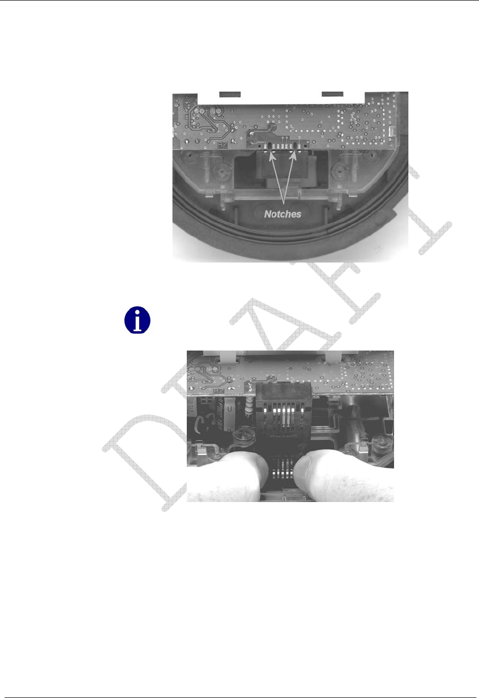
6 Snap the new module into the meter frame by aligning the notches at bottom of the
circuit board with the lower two snaps.
The module must be aligned properly in the snaps to avoid
damaging the connector or circuit board.
Installation
10 CENTRON® Polyphase Meter Technical Reference Guide
7 Replace the board-to-board connector by aligning the top of the connector with the
notches in the circuit board and pressing gently at the bottom of connector to mate the
connector to metrology board. Then, gently press the top of the connector to mate it to
the register module. The connector is seated correctly when you hear it snap into place.
Figure 5: Circuit Board Notches
Be sure to use the meter base for leverage instead of the LCD
holder. Pressure on the LCD holder may damage the
personality module.
Figure 6: Board-to-Board Connector, Bottom
Installation
CENTRON® Polyphase Meter Technical Reference Guide 11
8 Ensure the board-to-board connector is fully seated by pressing firmly in on the middle
of the connector.
Figure 7: Board-to-Board Connector, Top
9 Carefully replace the inner protective cover. Engage the top snaps first, taking care to
place the slot at the top of the cover over the IR light pipe. Failure to do so could break
the light pipe. Ensure that all four meter base tabs are engaged with the slots at the top
and bottom of the inner cover.
10 Place the cover over the meter base until the flange on the cover is flush with the flange
on the meter base.
11 Turn the cover clockwise until the locking tabs are fully engaged with the meter base.
CENTRON® Polyphase Meter Technical Reference Guide 13
CHAPTER 3
Operation: Base Metrology
In This Chapter
Metrology ............................................................................................................13
Surge Protection ..................................................................................................14
Sampling..............................................................................................................14
Voltage and Current Measurement......................................................................15
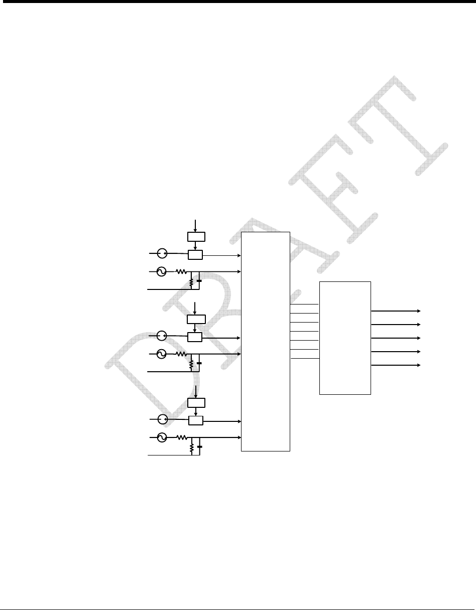
Metrology
The CENTRON Polyphase meter is a solid-state meter which uses the Hall Effect (one per
phase) to measure metered current and voltage dividers (one per phase) to measure metered
voltage as indicated in block diagram below.
DC
DC
AC
IC=IBias * ILine IC+
VC+
ILine
IBias
VC
VBias
Magnetic
Core
Hall
Sensor
DC
AC
IB=IBias * ILine IB+
VB+
ILine
IBias
VB
VBias
Magnetic
Core
Hall
Sensor
AC
IA=IBias * ILine IA+
VA+
ILine
IBias
VA
Magnetic
Core
Hall
Sensor
A/D DSP
Wh
VAh
VARh
PF
LED
VBias
Figure 8: CENTRON Polyphase Metrology
The metrology performs the direct sampling of the voltage and current waveforms and the
raw processing of these samples to compute all the energy quantities. It is comprised of a
dedicated microprocessor and an analog-to-digital (A/D) converter. Low level signals
proportional to the service voltages and currents are connected to the analog inputs of the
A/D converters. These converters, which are contained in one package, individually sample
the signals and send the digital results to the microprocessor 1,920 times per second. The
microprocessor takes these samples, applies precision calibration corrections and computes
all the quantities required for the specific meter configuration.
Operation: Base Metrology
14 CENTRON® Polyphase Meter Technical Reference Guide
Surge Protection
Surge protection for the electronics in the CENTRON POLYPHASE meter is provided by
Metal Oxide Varistors (MOVs). MOVs are clamping devices that allow voltage up to a
limit, and then increasingly conduct current to prevent the voltage from exceeding
the limit. The MOVs on the power supply board are connected directly across the voltage
inputs to the meter. Although this approach requires very large MOVs, it prevents high
voltages from appearing on or near the electronic boards giving the CENTRON
POLYPHASE meter superior performance when exposed to extremely high-voltage surges.
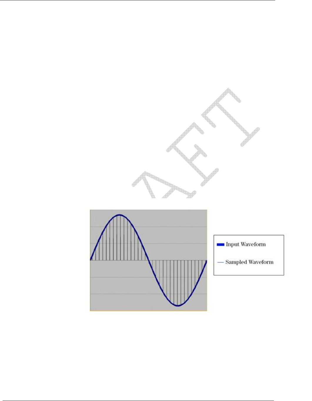
Sampling
The analog-to-digital converter samples each phase voltage and current signal 32 times per
line cycle and sends the digital values immediately to the microprocessor. This amounts to
32 samples per cycle at 60 Hz. Each time a new set of digital samples are received by the
microprocessor, it calculates all of the selected metrological quantities.
Figure 9: Sampled Waveform
At this sampling rate, harmonics to the 15th are measured. The high rate of the sampling
enables the CENTRON POLYPHASE meter to measure energy quantities accurately under
high harmonic distortion conditions. The sampling continues uninterrupted as long as the
meter is powered up. All other processing is done in the background between samples. From
the continuous train of digital samples on each of the six channels, current, voltage, active
energy, reactive energy, and apparent energy quantities are computed.
Operation: Base Metrology
CENTRON® Polyphase Meter Technical Reference Guide 15
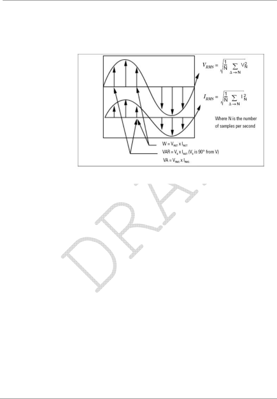
Voltage and Current Measurement
Figure 10: Voltage and Current Measurement
CENTRON® Polyphase Meter Technical Reference Guide 17
CHAPTER 4
Operation: CP1S Version
In This Chapter
Physical Description............................................................................................18
Registers ..............................................................................................................18
LCD Display Function.........................................................................................19
Testing, Troubleshooting and Maintenance.........................................................22
The kWh only version of the CENTRON Polyphase meter is available with an LCD
personality module to register energy accumulation.
Figure 11: CP1S LCD Personality Module
The LCD module may be ordered with a 5x1 or 4x10 register for self-contained meters, and
a 5xTR or 4xTR register for transformer-rated meters.
The kWh only version of the CENTRON Polyphase meter not only provides very accurate
measurement for energy accumulation for today's needs, but also provides a platform for
easy upgrade to higher functionality in the future.

Operation: CP1S Version
18 CENTRON® Polyphase Meter Technical Reference Guide
Physical Description
The CENTRON Polyphase meter Personality Modules snap into the meter register
mounting brackets to ease installation of the board.
The LCD module is connected to the metrology board using the board-to-board connector.
The following information is sent to the LCD module from the metrology board:
Reference voltages
Energy data
Basic status information
A connector is located at the 12 o'clock position behind the LCD for resetting the energy
register. This is done using the ZRO-C2A Resetter.
Need new photo
Registers
Kilowatt Hours
The modules display energy in increments of whole values of kWh. Standard operation for
all modules is to add forward and reverse energy flow. Therefore, if the meter is inverted,
the registers will accumulate in the forward direction, thus providing uni-directional
operation. At the time of order, the LCD module can be selected to have a detent register.
Programmed at the factory, this feature will cease registration while the meter is inverted, or
power flow is otherwise reversed. The module can also be selected to have a net register.
This feature is factory programmable and will subtract registration while the meter is
inverted, or power flow is otherwise reversed.
Operation: CP1S Version
CENTRON® Polyphase Meter Technical Reference Guide 19
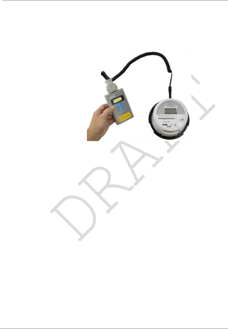
Resetting Values
The ZRO-C2A resets the energy register through a direct connection to the connector at the
12 o'clock position on the LCD and R300 modules.
Figure 12: ZRO-C2A Resetter Connected to the CENTRON
The ZRO-C2A is a pocket-sized handheld device for resetting the electronic meter readings
in the CENTRON Polyphase LCD kWh meter (CP1S) and the R300 meter (CP1SR). The
ZRO-C2A also resets the tamper indicators in the CP1SR.
The ZRO-C2A requires that the meter Not Be Powered. Wait three (3) seconds after power
removal to install the probe to ensure the meter has had sufficient time to power down. The
device connects to the CENTRON Polyphase meter through a hole in the plastic inner cover
located at the 12 o’clock position on the meter. Extending from the ZRO-C2A is a cable
terminating in a connector which mates to the programming connector of the CENTRON.
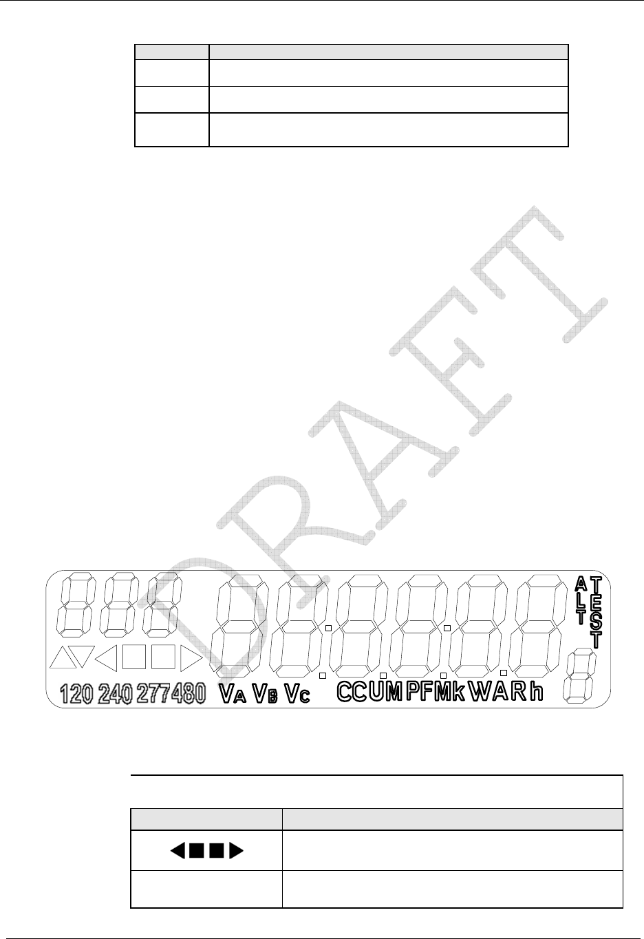
LCD Display Function
The following sections describe the LCD for the CENTRON Polyphase meter.
The LCD module is shown below. This display uses five 7-segment digits, three icons to
indicate the type of displayed data, three icons to represent a watt disk emulator, and three
icons for voltage indication. The display may be configured for either four or five digits and
will roll over at 100,000 kWh.
This module is compatible with the ZRO-C2A Resetter.
Need new photo

Operation: CP1S Version
20 CENTRON® Polyphase Meter Technical Reference Guide
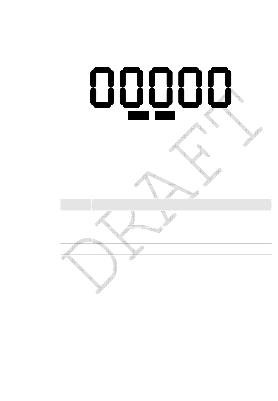
Non-Detented Register
The Non-Detented Register displays the delivered energy plus received energy.
kWhVAVBVC
Figure 13: Non-Detented Register (kWhd + kWhr)
Detented Register
The Detented Register addresses applications requiring the reading of delivered kWh only.
Received energy is discarded.
DET kWhVAVBVC
Figure 14: Delivered kWh with Detent Enabled (kWhd)
Net Register
The Net (kWh) Register addresses applications requiring residential net metering points. Net
kWh is the delivered kWh to the customer minus any received kWh from the customer.
NET kWhVAVBVC
Figure 15: Net kWh (kWhd - kWhr)
Operation: CP1S Version
CENTRON® Polyphase Meter Technical Reference Guide 21
Segment Check
The Segment Check Register addresses applications requiring display scrolling between
kWh and a full segment check. See Display Timing (on page ) 21 for factory programming
options.
NET DET kWhVAVBVC
Figure 16: Segment Check
Factory Programming Options
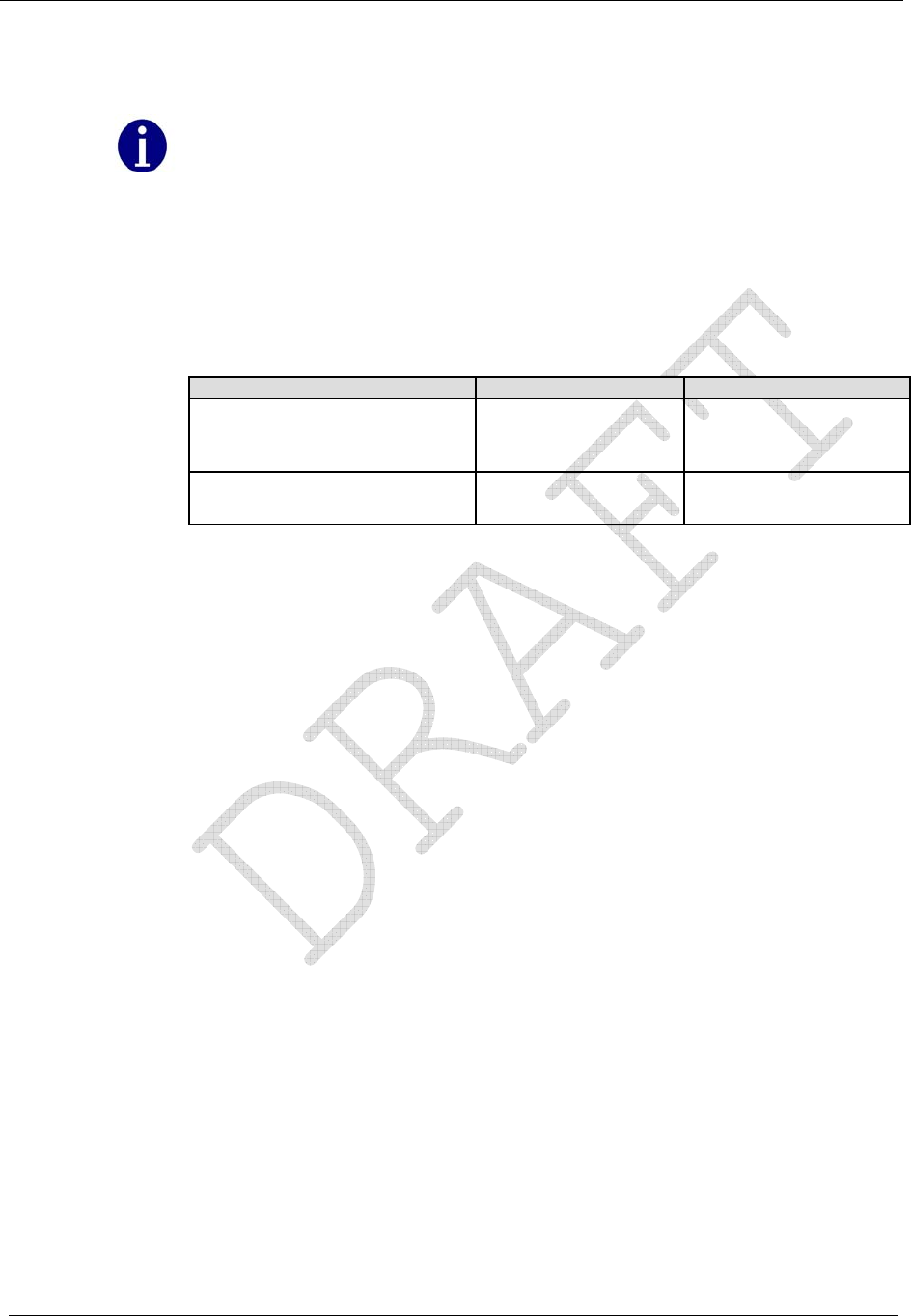
Display Timing
The display will scroll between the billing register and the segment check mode based on
the factory programming option.
Option Description
1 7 second billing register display, 1 second blank, 7 second segment
check display (7/7)
2 7 second billing register display, 1 second blank, 1 second segment
check display (7/1)
3 Only the billing register is displayed (7/0)
Digits and Multipliers
The following digit and multiplier settings are available for factory programming:
4 digits x 1 kWh
4 digits x 10 kWh
5 digits x 1 kWh

Operation: CP1S Version
22 CENTRON® Polyphase Meter Technical Reference Guide
Testing, Troubleshooting and Maintenance
Diagnostic Display OFF Period Notes
Metrology message stopped for
greater than 15 seconds and
less than 10 minutes
Error Missing message with
diagnostic flag also
written to the memory
Power up with Phase A, B, and
C voltage equal to 0 degrees noSEr
CENTRON® Polyphase Meter Technical Reference Guide 23
CHAPTER 5
Operation: CP1SR Version
In This Chapter
Standard Consumption Message (SCM)..............................................................24
Interval Data Message (IDM)..............................................................................24
Physical Description............................................................................................25
Registers ..............................................................................................................25
Transmission Scheme..........................................................................................27
Tamper Detection ................................................................................................28
Retrofitting the CP1SR Personality Module........................................................29
Testing, Troubleshooting and Maintenance.........................................................30
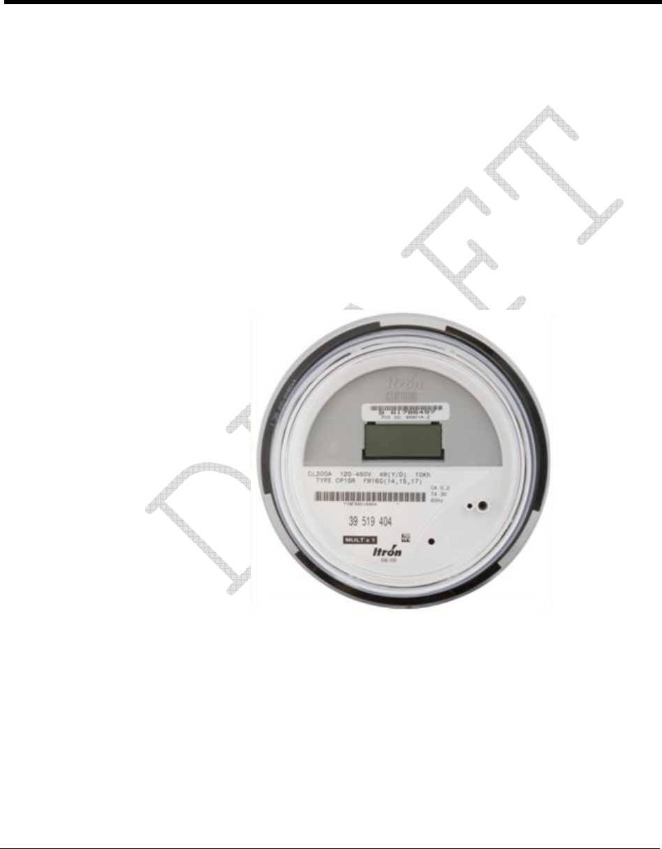
The CP1SR module is a one-way, unlicensed radio frequency (RF) personality module that
attaches to the CENTRON Polyphase meter base (See the figure below). It offers a cost-
effective solution for the endpoints in automatic and off-site meter reading applications.
Figure 17: CENTRON CP1SR Meter

Operation: CP1SR Version
24 CENTRON® Polyphase Meter Technical Reference Guide
Standard Consumption Message (SCM)
Utilizing the 96-bit Itron Standard Consumption Message protocol (SCM), the CP1SR
provides the energy (kWh) consumption, module ID number, tamper indications, meter
type, and error checking information in each radio frequency transmission. Within the 96-bit
SCM, 26 bits are allocated to the module ID number for meter identification (also referred
to as ERT ID number).
The CP1SR uses frequency hopping and transmits within the unlicensed 910 to 920 MHz
band on an average of once per second. In order to avoid interference from other devices,
the transmission frequencies and time interval between transmission cycles are completely
random in nature.
The CP1SR is factory programmed with tuning information, module ID, tamper indicators
(ITPR and RTPR), meter type, energy consumption, and scaling factor. The program and all
register information are stored in non-volatile memory in the event of a power outage. Upon
power restoration, all of the information in the non-volatile memory is restored to the
appropriate registers.
The ERT type 7 message indicates that the device is sending this message supports
transmitting a single SCM in the XXXXX format.
Interval Data Message (IDM)
The ERT type 7 SCM and an ERT type 24 IDM message indicates that the device sending
this message supports transmitting a single SCM with an XXXXX.XX format. The type 24
ERT indicates that it is an IDM message.
The RF Personality Module allows meter data to be collected automatically, helping to save
time, improve reliability, increase accuracy, and ensure data security.
The R300 IDM is a RF Personality Module based on the CENTRON Polyphase solid-state
metering platform. Kilowatt-hours and tamper data are reported through RF transmissions.
The R300 IDM module provides both baseline and advanced data collection functionality,
including interval data recording and enhanced tamper reporting capability. The R300 IDM
delivers the Standard Consumption Message to any of Itron’s radio-based data collection
technologies, including handheld computers (OMR), a vehicle-based Mobile AMR unit such
as the Mobile Collector, or a network data collection solution such as the Itron Fixed
Network or MicroNetwork. In addition, the R300 IDM is also capable of delivering the
Interval Data Message to the Itron Fixed Network AMR system to calculate ANSI standard
demand, time-of-use, and load profiling information.

Operation: CP1SR Version
CENTRON® Polyphase Meter Technical Reference Guide 25
Physical Description
The CP1SR personality module is constructed of a flame retardant printed circuit board
material which supports the discrete, surface-mounted, and integrated circuit components. A
microstrip etched on the circuit board serves as the RF antenna. The CP1SR personality
module easily snaps into the meter module mounting bracket. This module is then
electronically attached to the metrology board via a board to board connector. The following
information is sent to the personality module from the base metrology board:
Line voltages
Energy data
Basic status information
The CP1SR contains contacts on the module board, located at the 12 o'clock position behind
the LCD, for resetting the energy register and tamper counters. This can be accomplished
with the ZRO-C2A Resetter.
The CP1SR uses a unique module identification number, provided by Itron. This ID number
is contained in each message transmission and is used by the handheld and billing system to
determine meter identity and location. This ID number, which is contained on a bar-coded
label, is placed on the LCD housing directly above the LCD display.
Registers
Display
The CP1SR personality module is only available with a liquid crystal display, LCD. The
LCD is automatically adjusted for contrast over the operating temperature range.
NET DET kWhVAVBVC
Figure 18: CP1SR LCD
This module can be configured to display either four or five digits of energy consumption
and will rollover at 100,000 kWh for all meters. The self-contained meters can be
programmed to display normal kWh consumption (5X1 register configuration) or tens of
kWh consumption (4X10 register configuration). If the CP1SR is programmed for a 4x10
display, a “Mult by 10" label is placed on the module to the left of the LCD display. Thus,
the actual energy consumption is obtained by multiplying the value on LCD display by 10.

Operation: CP1SR Version
26 CENTRON® Polyphase Meter Technical Reference Guide
The transformer rated meters can be programmed to display either a 5xTR or 4xTR. In order
to determine the actual energy consumption, the display reading needs to be multiplied by
the transformer ratio (TR). If the transformer ratio is 1, then the reading on the display is the
actual energy consumption.
The LCD display contains an electronic load indicator (or watt disk emulator). The disk
emulator is three square segments in the lower right-hand corner of the display, which scroll
in the direction of energy flow. The LCD contains voltage indicators for A, B, and C phase.
These indicators will blink if nominal voltage falls below 20% of reference (A phase at
power up). These indicators will turn off if the voltage is below 96 volts.
Icons are illuminated on the display when the meter is programmed with a non-standard
algorithm. The LCD will display DET for detented energy and NET for net energy. There is
no additional indicator for the standard undetented configuration (i.e., where reverse energy
is accumulated in the forward register).
Factory programmable multipliers are available for CL20 (x20, x40 and x80) applications.
This allows the meter to display and transmit via RF primary readings. Meters are labeled
accordingly when factory programmed.
The display will scroll between the billing register and the segment check mode based on
the factory programming option.
Option Description
1 7 second billing register display, 1 second blank, 7 second segment
check display (7/7)
2 7 second billing register display, 1 second blank, 1 second segment
check display (7/1)
3 Only the billing register is displayed (7/0)
Electronic Detent
The CP1SR module displays energy in increments of whole values of kWh. Standard
operation for this module is to accumulate both forward and reverse energy flow in the
positive direction. However, the CP1SR personality module is available with an electronic
detent that will cause the meter to ignore reverse energy flow. Therefore, if the meter is
inverted, the registers will accumulate in the forward direction only, thus providing
uni-directional operation. At the time of order, the CP1SR module can be selected to have a
detent register.
When the meter is undetented, both forward and reverse energy will be accumulated.
Therefore, the electronic load indicator will flash at a rate equal to the energy consumption,
regardless of the direction of the energy flow.
When the electronic detent is enabled, only forward energy flow will be accumulated.
Operation: CP1SR Version
CENTRON® Polyphase Meter Technical Reference Guide 27
Net Metering
The CP1SR module is available with the option of net metering capability. When the net
option is enabled, received energy is subtracted from delivered energy. The net energy value
is then displayed on the register.
Resetting Values
The ZRO-C2A Resetter zeros both the energy registers and tamper counters by direct
connection to the CP1SR module. For more information, see the ZRO-C2A Handheld Meter
Resetter for the CENTRON C1S and C1SR Operating Instructions.
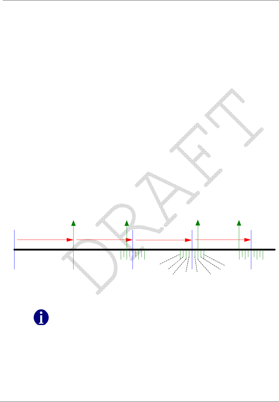
Transmission Scheme
A transmission cycle contains a wait period before and after each message burst and a
period of random silent time. The silent time is determined by the scaling factor, which sets
a minimum and maximum silent time between each transmission cycle.
The transmission frequencies (within the 910-920 MHz band), the frequency hopping
pattern, and the time interval between transmission cycles are completely random in nature.
This randomness provides a method for avoiding interference with transmissions from other
devices. The figure below shows an example of the CENTRON Polyphase meter CP1SR
transmission cycle containing one message burst.
Power
up
0 – 30 Sec . 30 Sec . 30 Sec . 30 Sec .
First
Transmission
2 Sec
1.5 Sec
1.0 Sec 0.5
Sec 0.5
Sec 1. 0 Sec
1.5 Sec
2 Sec
Figure 19: CENTRON-IDM High Power SCM/IDM Transmission Scheme
In the figure above, if the transmission is an IDM/SCM message pair, then the SCM
occurs 250 milliseconds following the completion of the IDM.

Operation: CP1SR Version
28 CENTRON® Polyphase Meter Technical Reference Guide
FCC Regulations
The CP1SR communicates in the unlicensed, 910-920 MHz band governed by the US Code
of Federal Regulations (CFR) Title 47, Part 15 Radio Frequency Devices, Sub Part C
Paragraph 249 Intentional Radiator.
Changes or modifications not expressly approved by
Itron could void the users authority to operate the
equipment.
Tamper Detection
The CENTRON Polyphase CP1SR features the Itron patented method of tamper detection
that senses both meter removal and meter inversion. The removal tamper (RTPR)
increments a counter each time the meter is abruptly removed from a live meter socket. The
tamper counter utilizes a tilt switch to detect when the meter is removed from a meter
socket.
Testing the CENTRON CP1SR Tamper Counter
SCM Testing
In order to test the power removal counter, the meter must sense a shaken condition
associated with a power outage.
1 Place the meter in a socket.
2 Apply power to the meter.
3 Remove the meter from the live socket.
4 Replace the meter in the socket.
The meter has incremented the removal tamper counter.
The CP1SR uses the power outage (the meter being removed from a live socket) in
conjunction with the meter being shaken simultaneously to increment the power removal
counter.
The inversion counter increments when the meter senses reverse current flow. The
metrology board senses reverse power flow and sends this status to the CP1SR personality
module. The CP1SR then increments the counter and transmits the count.
As part of the 96-bit Standard Consumption Message, 4 bits are allocated for tamper
indications, which include the power removal and meter inversion counters. The ReadOne®
Pro handheld reader converts the 4 bit binary number to its equivalent value between 0 and
15. The table below shows the removal and inversion information based on the reported
tamper count. For example, a tamper count of 6 on the ReadOne Pro would translate as 1
meter removal and 2 meter inversions since the last read.
Operation: CP1SR Version
CENTRON® Polyphase Meter Technical Reference Guide 29
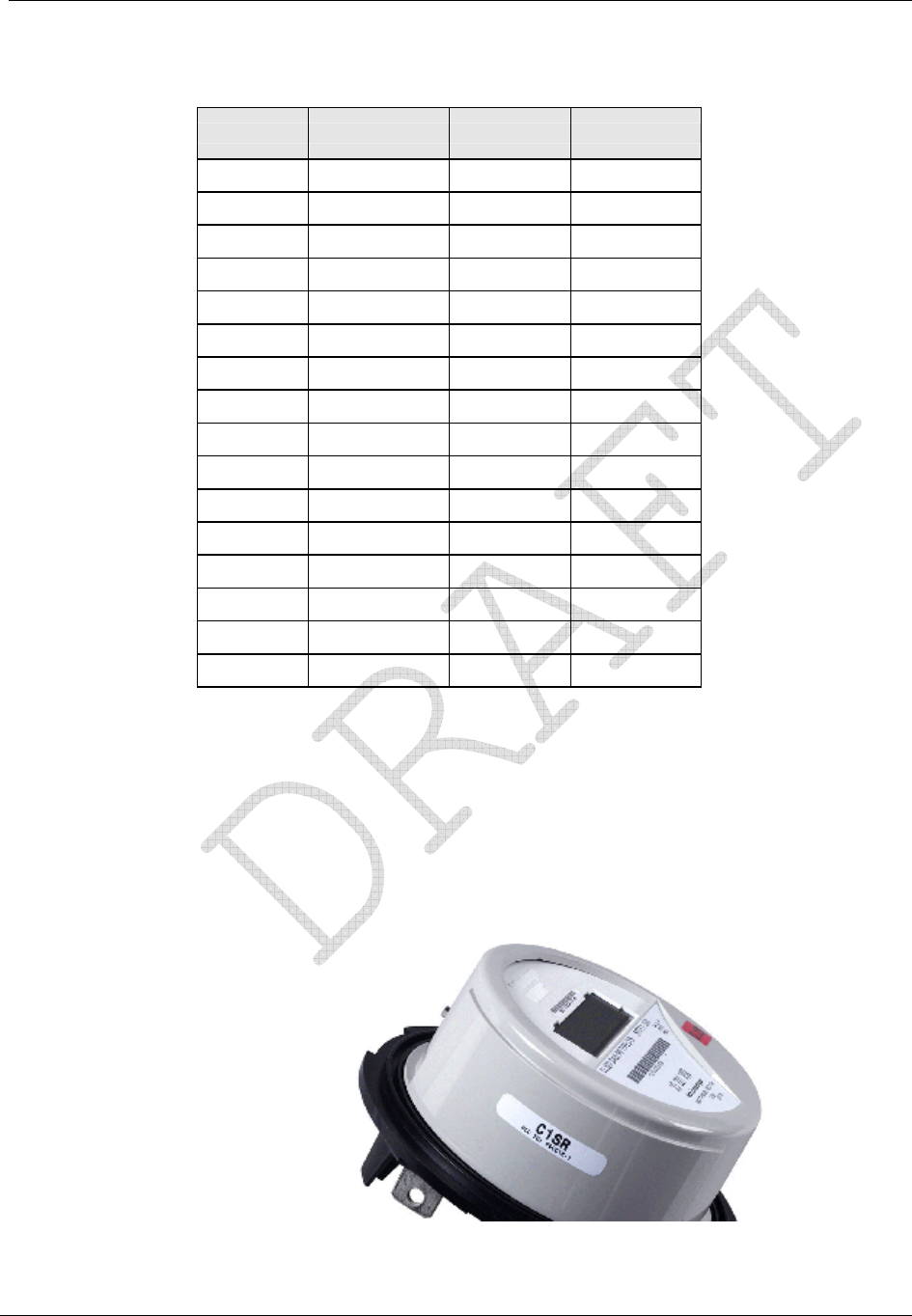
ReadOne Pro Tamper Count:
Binary Tamper Count Inversion Removal
0000 0 0 0
0001 1 1 0
0010 2 2 0
0011 3 3 0
0100 4 0 1
0101 5 1 1
0110 6 2 1
0111 7 3 1
1000 8 0 2
1001 9 1 2
1010 10 2 2
1011 11 3 2
1100 12 0 3
1101 13 1 3
1110 14 2 3
1111 15 3 3
Retrofitting the CP1SR Personality Module
The CENTRON R300 is a one-way radio frequency personality module that transmits
within the unlicensed 910-920 MHz frequency band governed by the US Code of Federal
Regulations (CFR) Title 47, Part 15 Radio Frequency Devices, Sub Part C Paragraph 249
Intentional Radiator. Any device operating within this unlicensed frequency band must
contain an FCC Identification number. Therefore, the FCC ID Label included in the Retrofit
Kits must be placed on the meter as shown below.
Figure 20: CP1SR FCC Label Location
Operation: CP1SR Version
30 CENTRON® Polyphase Meter Technical Reference Guide
Recent revisions to the CP1SR module include placing the FCC ID on the module itself.
Changes or modifications not expressly approved by Itron could void the user's
authority to operate the equipment.
To retrofit an existing meter with an R300 module, see Retrofitting with Personality
Modules (on page 8).
Testing, Troubleshooting and Maintenance
Diagnostic Display OFF Period Notes
Metrology message stopped for
greater than 15 seconds and
less than 10 minutes
Error Missing message with
diagnostic flag also
written to the memory
Power up with Phase A, B, and
C voltage equal to 0 degrees noSEr

CENTRON® Polyphase Meter Technical Reference Guide 31
CHAPTER 6
Operation: CP1SD/T/L Version
In This Chapter
Controls and Indicators........................................................................................31
Factory Reset.......................................................................................................37
Application of Power and Power-up....................................................................37
Power Down Procedures......................................................................................38
Operating Modes .................................................................................................39
Display Modes.....................................................................................................40
Registers ..............................................................................................................47
Interrogation and Programming...........................................................................49
Time-of-Use (TOU).............................................................................................50
Load Profile.........................................................................................................53
Event Log ............................................................................................................56
Security Codes.....................................................................................................58
Firmware Upgrades .............................................................................................60
R300 Series..........................................................................................................60
SiteScan On-Site Monitoring System..................................................................61
Testing, Troubleshooting, and Maintenance........................................................82
This chapter describes the basic operation of the CENTRON Polyphase meter D/T/L
Register. It also explains how to configure the D/T/L Register while providing detailed
information on energy and demand multimeasurement functions, as well as Time of Use
(TOU), Load Profile, KYZ, and communications board options.
Controls and Indicators
All controls and indicators are shown in the figure below.
Add New Photo
Callout Description
1Liquid Crystal Display (LCD)
2Magnetic Switch
3Demand Reset Button
4Test Mode Button
5Battery Slot
6Battery Connector
Operation: CP1SD/T/L Version
32 CENTRON® Polyphase Meter Technical Reference Guide
Callout Description
7Optical Port
8Infrared Test LED
9Nameplate
Demand Reset Button
The demand reset button is located at the 6 o’clock position on the meter face. The demand
reset mechanism is used to initiate a demand reset. The demand reset cover mechanism can
be physically locked with a meter seal, or disabled by the meter programming software.
Infrared Test LED
One infrared (IR) LED is located at the 3 o’clock position of the meter nameplate. The LED
can be configured to pulse based on any of the following energy quantities:
Wh delivered, received
Varh delivered, received, Q1, Q4
VAh delivered, received (arithmetic or vectorial)
Liquid Crystal Display (LCD)
The CENTRON Polyphase meter features a versatile ANSI C12.10-compliant, 104-segment
liquid crystal display (LCD). The LCD with all segments lit is shown in the figure below.
There are several static indicators available on the LCD as described in the table below the
figure.
Figure 21: CENTRON Polyphase Meter LCD
Static Indicators
Indicator Description
Load Emulator (-> for positive, <- for negative)
888 888888 Nine digits (7 segments each) for display of
alphanumeric information
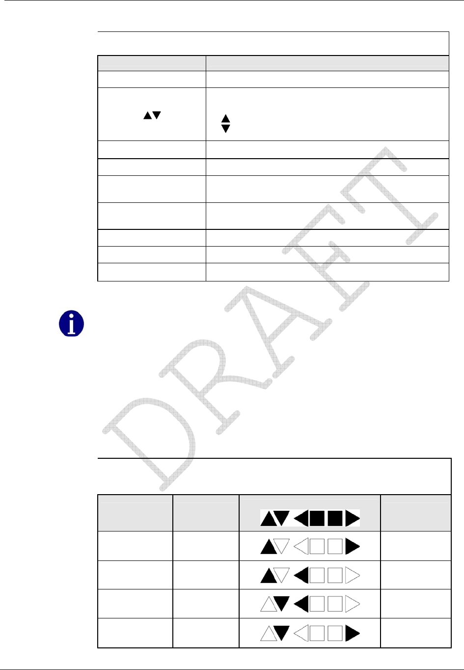
Operation: CP1SD/T/L Version
CENTRON® Polyphase Meter Technical Reference Guide 33
Static Indicators
Indicator Description
VA, VB, VC Indicators for phase voltages being present
Reactive Load Indicator:
No arrow for unity PF
for positive [delivered] (lag)
for negative [received] (lead)
120 240 277 480 Nominal Voltage Indicator (one value appears at a time)
EOI End of Interval (Registers - Dmd)
Scr Loc Scroll Lock (indicates temporary scroll lock of a display
item)
SEL nor, SEL Alt, SEL
tooL Selection of Normal, Alternate, or Toolbox display
sequence
nor diSP Entry into Normal Mode.
TEST Entry into Test Mode.
ALT TEST Entry into Test Alternate Mode.
The indicators shown in the table above actually display in a digital readout font;
some characters may display as upper case.
Power Flow
The D/T/L Register display can be configured to provide instant power flow feedback. The
load emulator and reactive load indicator identify in real time which quadrant of the power
circle the power is flowing through. The meter display identifies the active quadrant as
shown in the following table.
D/T/L Register Reactive Load Indicator
Reactive (Var)
Direction Power (W)
Direction
Meter Display
Active
Quadrant
Vars delivered Watts
delivered Q1
Vars delivered Watts received Q2
Vars received Watts received Q3
Vars received Watts
delivered Q4
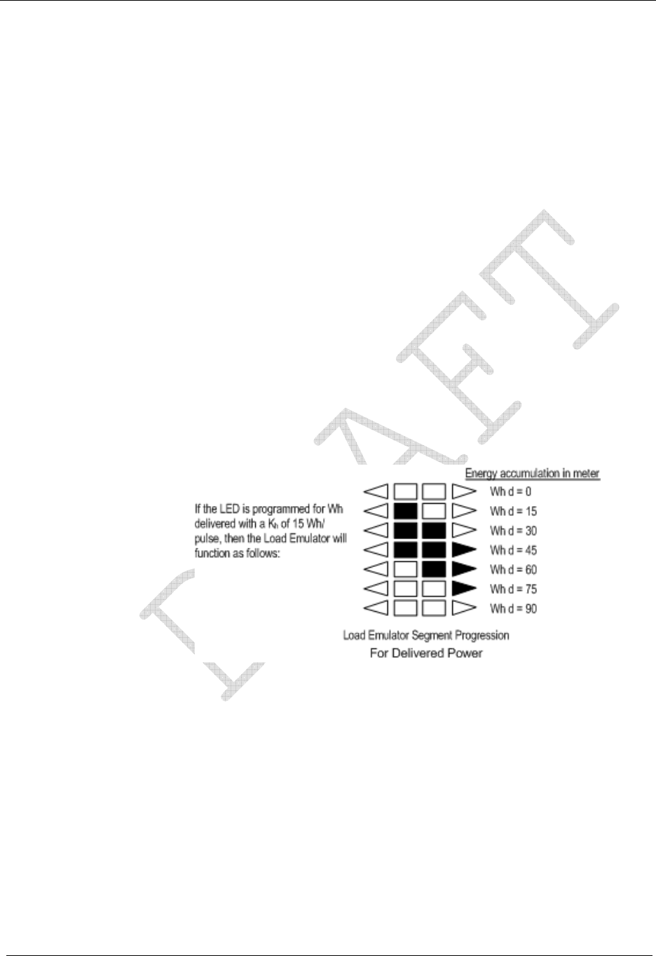
Operation: CP1SD/T/L Version
34 CENTRON® Polyphase Meter Technical Reference Guide
Load Emulator
The Load Emulator follows the Infrared Test LED. For each pulse of the Test LED, the
Load Emulator increments one segment. The operation of the Load Emulator depends on the
quantity being pulsed.
If the quantity being pulsed is “Delivered-Only”, then the Load Emulator scrolls to the
right when energy is being delivered and lights the left arrow when energy is being
received.
If the quantity being pulsed is “Received-Only”, then the Load Emulator scrolls to the
left when energy is being received and lights the right arrow when energy is being
delivered.
If the quantity being pulsed is “Delivered and Received”, then the Load Emulator
scrolls to the right when energy is being delivered and scrolls to the left when energy is
being received.
When the meter is in Toolbox mode, the Load Emulator does not follow the Test LED.
Instead, the operation of the Load Emulator depends on the quantity that is currently being
displayed. If the quantity being displayed is a Phase quantity, then the Load Emulator scrolls
to the right if energy flow on that phase is currently delivered or scrolls to the left if energy
flow on that phase is currently received. If the quantity being displayed is a Diagnostic
Counter, then the Load Emulator is turned off.
The figures below represents a typical progression of the Load Emulator segments:
Figure 22: Load Emulator Segment Progression for Delivered Power

Operation: CP1SD/T/L Version
CENTRON® Polyphase Meter Technical Reference Guide 35
Figure 23: Load Emulator Segment Progression for Received Power
Several uni-directional quantities are available. When these quantities are programmed to
LED, both the LED and the load emulator will function for delivered and received
quantities.
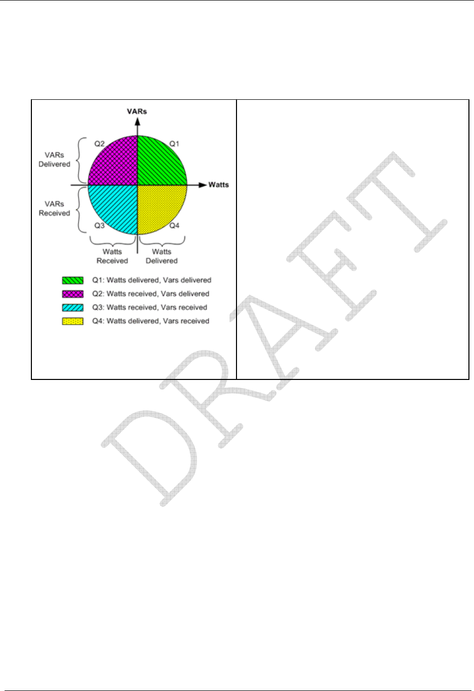
Operation: CP1SD/T/L Version
36 CENTRON® Polyphase Meter Technical Reference Guide
Power Circle Quadrants
The following power circle diagram shows the quadrants for watts and vars delivered and
received.
Figure 24: Power Circle Diagram
The directional calculations in the CENTRON
Polyphase meter are as follows:·
• Watts delivered = (wattsQ1) + (wattsQ4)·
• Watts received = (wattsQ2) + (wattsQ3)·
• VA delivered = (VA while watts are in Q1) + (VA
while watts are in Q4)·
• VA received = (VA while watts are in Q2) + (VA
while watts are in Q3)·
• Var net delivered (while watts are delivered) =
(varQ1) - (varQ4)·
• Var net received (while watts are received) =
(varQ2) - (varQ3)·
• Var delivered (Lag) = (varQ1) + (varQ2)·
• Var received (Lead) = (varQ3) + (varQ4)
Magnetic Switch
The magnetic switch allows for manual switching between display modes as well as scroll
lock of display items. To activate the magnetic switch, hold the magnet to the location
shown in the figure below. For more information on using the magnetic switch, see
Magnetic Switch.
Add New Photo
Optical Port
The optical port is mounted on the meter cover. The optical port is a communication
interface from the meter to a PC. Interface to a PC is accomplished through a
communication cable which attaches to the optical port on one end and a PC serial port on
the other end. This interface cable can be powered by a DC TAP, an AC Adaptor, or the
PC’s COM Port. Communication through the optical port may be at 9600, 14400, 19200, or
28800 bps.

Operation: CP1SD/T/L Version
CENTRON® Polyphase Meter Technical Reference Guide 37
Test Mode Button
The Test Mode button is located at the 3 o'clock position under the meter cover. Pressing the
button activates Test Mode. Test Mode is indicated by the “TEST” annunciator on the lower
left of the LCD. Pressing the button a second time activates Test Alternate Mode, enabling
the user to test a different energy quantity with the IR LED. Test Alternate Mode is
indicated by the “TEST” and “ALT” annunciators on the lower left of the LCD. Pressing the
button a third time will exit Test Mode and activate the Normal display.
If the TEST button is disabled through programming, the meter will not enter Test
Mode when the button is pressed.
Factory Reset
To return the meter to its original factory settings, you must perform a factory reset. A
factory reset is also referred to as a “three button reset”.
All programming of the meter will be lost when a factory reset is performed.
All security codes are also cleared.
To perform a factory reset, do the following:
1 Activate the magnetic switch.
2 Press and hold the Demand Rest button.
3 Press and hold the Test Mode button.
4 While continuing to hold all buttons, cycle the power to the meter OFF, and then back
ON. You do not need to hold the buttons while turning the meter OFF, only while
turning it ON.
5 Once completed, the meter may possibly display "3BReset" or "NorDisplay" and all
segments will blink.
The original factory settings of the meter are restored.
Application of Power and Power-up
To energize all electronics, apply 120-480V (50/60 Hz) between A-phase and Neutral.
Do not power up the meter if the upper and lower housing are not
properly secured. Line-level voltages are present inside the housings.
Failure to follow this procedure could result in serious personal injury
or death.

Operation: CP1SD/T/L Version
38 CENTRON® Polyphase Meter Technical Reference Guide
Power Down Procedures
To de-energize all electronics, remove power from the meter.
A power outage is recognized any time the line voltage drops 20 percent below the lowest
nominal point of the voltage range. With a standard single phase power supply, a power
outage occurs when line voltage drops below 96 volts; with a polyphase power supply, a
power outage occurs when line voltage drops below 45 volts. When a power outage is
recognized, the D/T/L Register saves all billing values to non-volatile Flash memory.
Demand Meter
Restoration of AC power energizes the electronics and causes the meter to perform self-
diagnostic check procedures. The meter then retrieves all billing data from non-volatile
memory, begins measuring energy, and starts the process of calculating any demand values.
TOU/Load Profile Meters
All TOU/Load Profile meters have a battery installed. The battery allows the TOU and Load
Profile data in RAM to be maintained during a power outage. The battery also allows the
timekeeping circuitry in the meter to maintain the meter's clock during an outage. If a
battery is removed on a TOU/Load Profile meter during an outage, then the meter's clock
will be off by the duration of the outage and the TOU data and some Load Profile data will
be lost. Load Profile data is periodically committed to flash as described in the Load Profile
section.
Upon the return of AC power, the register undergoes a procedure similar to the initial
power-up. The meter performs self-diagnostic checks, data is retrieved from non-volatile
memory, and normal operation is resumed. The number of minutes of power outage
maintained while the meter was in carry-over operation, is added to the Time on Battery
register. Since the demand interval is synchronized to the top of the hour, the first demand
interval after a power outage may be shorter than the programmed interval value.
Cold Load Pickup
Normally, when power is restored to the meter after an outage, a new demand interval is
started and demand calculations begin immediately. The meter can be configured to
recognize a demand delay or cold load pickup (CLPU) time. If a CLPU is configured in the
meter, the meter will delay demand calculations for the configured amount of time—0 to
255 minutes in one-minute increments. For example, if a CLPU time of five minutes is
programmed into the meter, a power outage will cause the meter to wait five minutes after
power restoration before resuming demand calculations.
Defining CLPU as zero will cause demand calculations to restart immediately after
any recognized power outage.

Operation: CP1SD/T/L Version
CENTRON® Polyphase Meter Technical Reference Guide 39
Interval Make-up
Interval Make-up applies only to Load Profile meters.
During power-up processing, the Load Profile component checks if the duration of the
outage exceeds the configured minimum duration time. If it does, then at least one interval
will be tagged with an outage status. The interval that was active when outage occurred is
tagged as a partial interval due to the outage. If the outage ended in the middle of another
interval, then that interval is also tagged as a partial interval due to the outage. If any
intervals occurred in between, then those intervals are tagged as skipped intervals due to the
outage and their data will be all zeroes.
Operating Modes
The D/T/L Register has two operating modes: Normal Mode and Test Mode.
In the Normal Mode of operation, there are three display mode options: Normal Display
Mode, Alternate Display Mode, and Toolbox Display Mode.
In the Test Mode of operation, there are two display mode options: Test Display Mode and
Test Alternate Display Mode.
When the meter is placed in Test Mode, it ceases all normal billing functions. The
TEST switch can be used to control the operating mode of the D/T/L Register.
Normal Mode
Normal Mode is the standard mode of operation and the mode in which the meter
automatically starts when energized. Selected quantities are measured and processed in
billing registers. During this mode of operation, billing registers are saved in non-volatile
memory during power outages.
Test Mode
The meter can be placed into Test Mode either by pressing the TEST button or through
software communications. Manual use of the TEST button can be disabled via PC-PRO+
Advanced software.
If the TEST button is disabled through programming, the meter will not enter Test
Mode when the button is pressed.
While in Test Mode, the “TEST” annunciator is displayed on the LCD. When the Test
Mode is activated, all billing registers and certain non-billing registers are preserved in non-
volatile memory and restored when Test Mode is exited.

Operation: CP1SD/T/L Version
40 CENTRON® Polyphase Meter Technical Reference Guide
To exit Test Mode, press the TEST button. The meter will change display mode to Test
Alternate. Press the TEST button again. The LCD will display “nor diSP” signifying the exit
of Test Mode and entry into Normal Mode operation.
Test Mode Timeout
If the meter is left in Test Mode, the meter will automatically exit after a user-configurable
Mode Timeout. See the PC-PRO+ Advanced online help for more information on
configuring the Mode Timeout. This action prevents someone from accidentally leaving a
meter in Test Mode and thus losing billing data.
Test Mode Lockout
Activating Test Mode Lockout via the programming software will prevent entry into Test
Mode via manual Test Mode Switch activation.
Display Modes
The D/T/L Register has five display modes as shown in the table below: Normal, Alternate,
Test, Test Alternate, and Toolbox. Each display mode has a separate list of items
(quantities) it can display. The aggregate of items associated with a display mode is called a
display list. Test and Test Alternate modes employ the same display list. The CENTRON
Polyphase meter can display a maximum of 80 items. The display list is dynamically
configured through PC-PRO+ Advanced. The user can select as many items per mode
totaling up to 80 with at least one item in each display mode. The display items and
sequence of display, along with any desired annunciators or ID code number, are selected
during program setup, a feature of the PC-PRO+ Advanced programming software.
Operating Mode Display Mode Metrological LED Quantity
Normal
Normal
Alternate
Toolbox
Normal Mode Quantity
Alt Mode Quantity
Normal Mode LED
Selection
Test Test
Test/Alternate
Test Mode Quantity
Test Alt Mode Quantity
The following types of displayable items are available for the user-defined display lists:
Energy registers
Demand registers
Instantaneous registers
Self Read registers
SnapShot registers
Informational items (configuration, state informational items)
Numerical values may be displayed in various formats depending on configuration. For
example, kilo units, mega units, fixed decimal point, floating decimal point, and leading
zeros can all be configured.
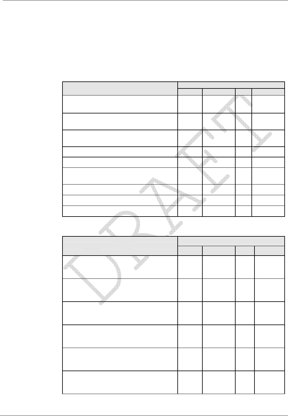
Operation: CP1SD/T/L Version
CENTRON® Polyphase Meter Technical Reference Guide 41
The following tables show items programmable for display in the modes indicated.
All of the display items in the next two tables may be selected by TOU Rate. They also may
be selected from the four Self Read buffers, the two Demand Reset Snapshot buffers, and
Last Season Self Read buffer.
Energy Data Display Items
Display Mode
Energy Data Display Item Normal Alternate Test Toolbox 1
Wh (delivered, received, net, uni-
directional) X X X
Varh (delivered [lag], received [lead], Net,
net delivered, net received, Q1, Q4) X X X
VAh (delivered, received; arithmetic &
vectorial) X X X
VAh lag (vectorial) X X X
Qh (delivered, received) X X X
Vh (Phase A, Phase B, Phase C,
Average) X X
Ah (Phase A, Phase B, Phase C) X X
V2h Aggregate X X
A2h Aggregate X X
Demand Data Display Items
Display Mode
Demand Data Display Item Normal Alternate Test Toolbox2
W Delivered (Max, Present, Previous,
Projected, Cumulative, Continuous
Cumulative) X X X
W Received (Max, Present, Previous,
Projected, Cumulative, Continuous
Cumulative) X X X
W Net (Max, Present, Previous,
Projected, Cumulative, Continuous
Cumulative) X X X
W Uni-directional (Max, Present,
Previous, Projected, Cumulative,
Continuous Cumulative)
Var Q1, Var Q4 (Max, Present, Previous,
Projected, Cumulative, Continuous
Cumulative) X X X
Var Delivered [lag: Q1+Q2] (Max,
Present, Previous, Projected, Cumulative,
Continuous Cumulative) X X X
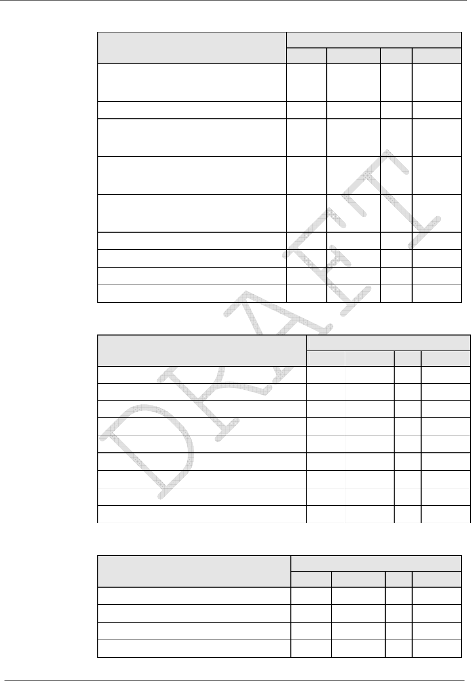
Operation: CP1SD/T/L Version
42 CENTRON® Polyphase Meter Technical Reference Guide
Display Mode
Demand Data Display Item Normal Alternate Test Toolbox2
Var Received [lead: Q3+Q4] (Max,
Present, Previous, Projected, Cumulative,
Continuous Cumulative) X X X
Var Net
VA Delivered [arithmetic or vectorial]
(Max, Present, Previous, Projected,
Cumulative, Continuous Cumulative) X X X
VA Received [arithmetic or vectorial]
(Max, Present, Previous, Projected,
Cumulative, Continuous Cumulative) X X X
VA Lag (Max, Present, Previous,
Projected, Cumulative, Continuous
Cumulative) X X X
Max A (per phase: A, B, C) X X
PF Average X X
Min P.F. X X
Coincident Demands (up to 4) X X
Instantaneous Data Display Items
Display Mode
Instantaneous Data Display Item Normal Alternate Test Toolbox3
Instantaneous W X X X
Instantaneous Var X X X
Instantaneous VA (arithmetic & vectorial) X X X
Instantaneous Volts (A, B, C) X X X
Instantaneous Amps (A, B, & C) X X X
Instantaneous P.F. X X
Instantaneous Frequency (Hz) X X
Instantaneous Current Phase Angles (A, B, C)
X
Instantaneous Voltage Phase Angles (A, B, C)
X
Informational Data Display Items
Display Mode
Informational Data Display Item Normal Alternate Test Toolbox4
Calibration Date & Calibration Time X X
Cold Load Pickup Outage Time X X
Current Transformer Ratio X X
Current Date, Day & Current Time X X
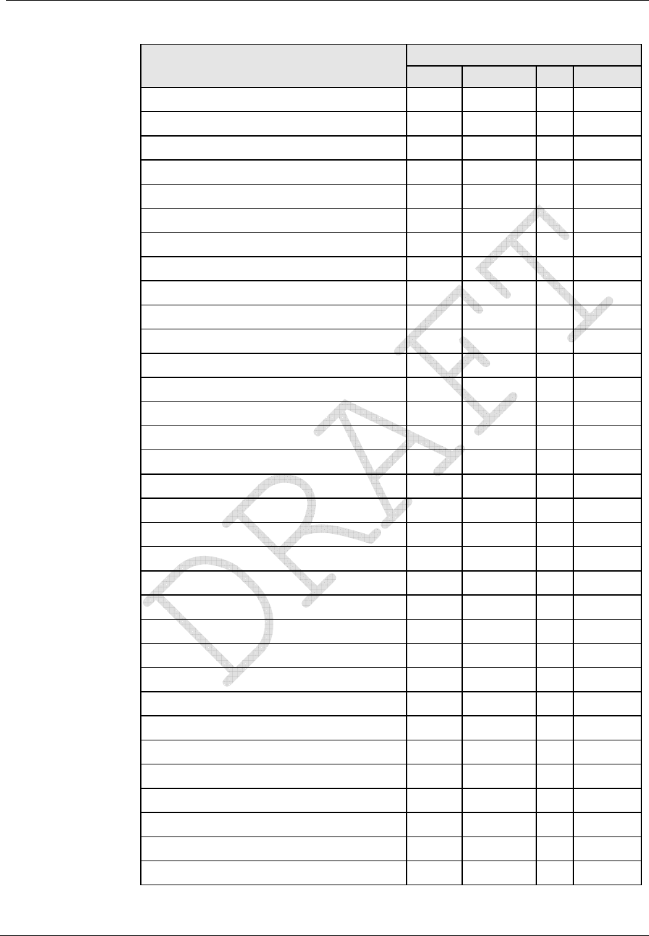
Operation: CP1SD/T/L Version
CENTRON® Polyphase Meter Technical Reference Guide 43
Display Mode
Informational Data Display Item Normal Alternate Test Toolbox4
Days Since Demand Reset X X
Demand Reset Count X X
Diagnostic Counters 1-5
X
Display On Time X X
Firmware Revision X X
Last Outage Date & Last Outage Time X X
Last Program Date & Last Program Time X X
Last Reset Date & Last Reset Time X X
Last Test Date & Last Test Time X X
Load Profile Pulse Weight 1-8 X X
Load Research ID X X
Last Season Self Read Registers X X
Meter ID & Meter ID 2 X X
Minutes on Battery X X
Normal Kh & Normal Kh #2 (Alternate Kh) X X
Number of Subintervals X X
Number of Test Subintervals
X
Last Interrogate Date & Time X X
Option Board Fields 1 - 3 X X
Outage Count X X
Percent VQ Log Full X X
Program Count X X
Program ID X X
Register Fullscale X X
Register Multiplier X X
RF ID 1-3 X X
Segment Test X X
Service Type X X
SiteScan Diagnostic Count X
Software Revision Number X X
Subinterval Length X X
Test Kh & Test Kh #2 (Test Alternate Kh)
X
Test Subinterval Length
X

Operation: CP1SD/T/L Version
44 CENTRON® Polyphase Meter Technical Reference Guide
Display Mode
Informational Data Display Item Normal Alternate Test Toolbox4
Time Remaining in Demand Subinterval X X X
Time Remaining in Test Mode
X
TOU Expiration Date X X
Transformer Ratio X X
User Data 1-3 X X X
Voltage Transformer Ratio X X
Magnetic Switch
The magnetic switch enables scroll lock of display items as well as manual switching
between display modes. The magnetic switch is located near the front of the meter face in
the 10 o'clock position.
Scroll Lock
When the magnetic switch is activated for one second and removed, the “ScrLoc” message
appears on the LCD and the display locks on the current display item. The value displayed
on the locked screen will continue to be updated every second. The user may scroll to the
next item by again momentarily activating the magnetic switch. The display will remain in
the scroll lock condition until a mode timeout occurs or until the display mode is changed.
Changing Display Modes
When the magnetic switch is activated for four seconds, the display may indicate the
“ScrLoc” condition (if not already in scroll lock) and then, enter into a display mode
selection menu. The menu options are: “SELnor”, “SELALt”, and “SELtooL”. The desired
mode can be selected by removing the magnet when it is being displayed.
Mode Timeout
When the display is put into display modes other than Normal display (Alternate, Toolbox,
Scroll Lock, Test, or Test Alternate display modes), the meter will return to normal
operation after a programmable Mode Timeout expires. The Mode Timeout can be
configured from 1 to 255 minutes using the meter programming software.
Normal Display Mode
The Normal Display Mode is the default display when the meter is energized and when the
meter is in Normal Operating Mode. When Mode Timeout occurs from any other display
mode, the display returns to Normal Display Mode.
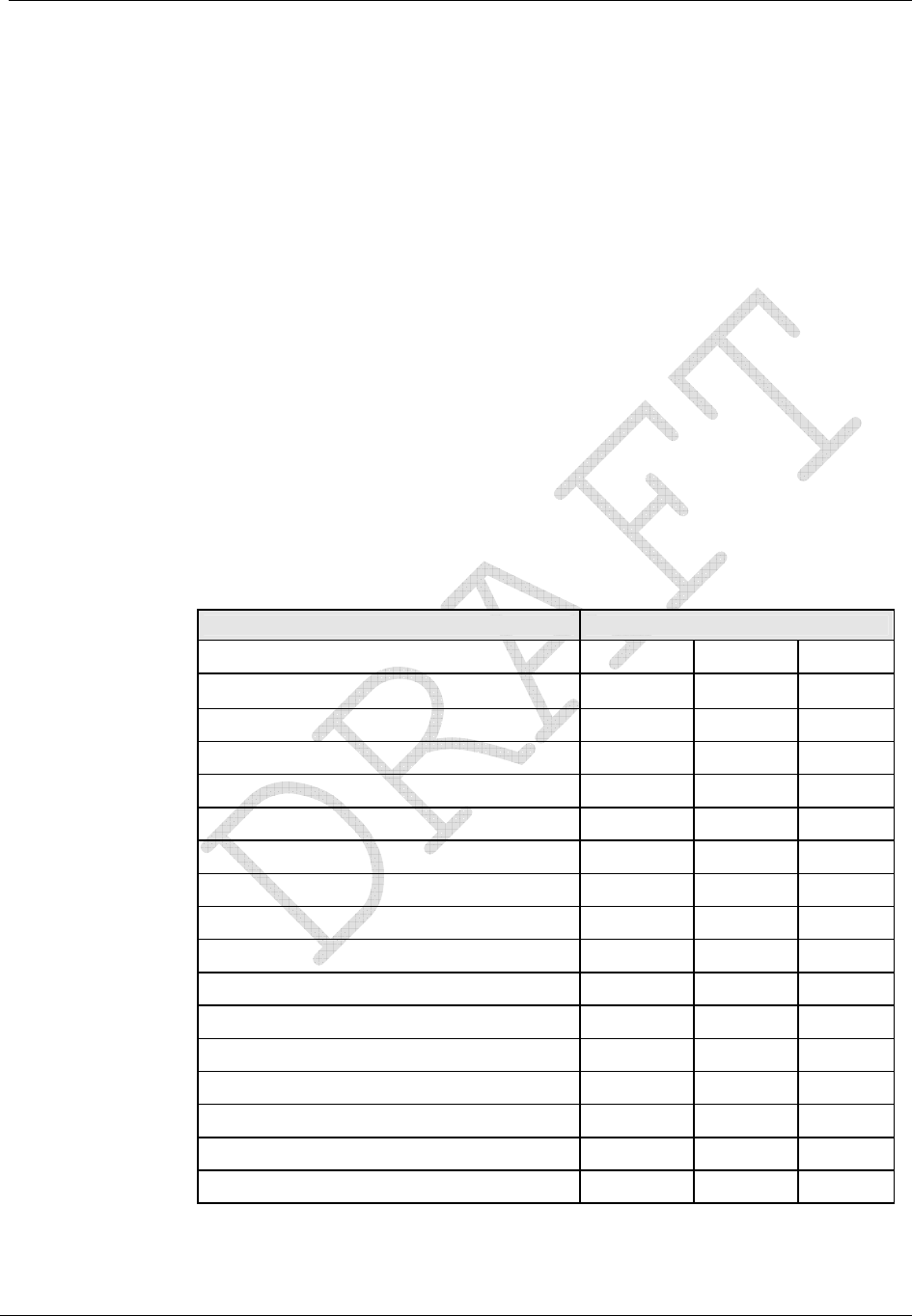
Operation: CP1SD/T/L Version
CENTRON® Polyphase Meter Technical Reference Guide 45
Alternate Display Mode
The Alternate Display Mode is functionally identical to the Normal Mode. The meter itself
still operates under normal measurement, but the display sequence can be programmed to
show a different set of displayable items from those in the Normal Display Mode.
While in Alternate Display Mode, the “ALT” annunciator on the lower left of the display
designates activation of the Alternate Display Mode. Upon completion of the Mode Time-
out period, the meter automatically returns to the Normal Display Mode.
Toolbox Display Mode
Toolbox Display Mode is identical to Normal Mode except that the list of displayable items
is a fixed list dependent on the service type.
You can enter the Toolbox Mode from either Normal or Alternate Mode. While in Toolbox
Mode, a flashing “TEST” appears on the left side of the display.
Once activated, the Toolbox Mode scrolls through the list of per-phase items and diagnostic
counters. The table below shows an example of a 3-element meter.
Description Display
Phase A voltage angle PhA 0.0° U
Phase A voltage PhA xxx.x U
Phase A current angle PhA xxx.x° A
Phase A current PhA xxx.x A
Phase B voltage angle PhB xxx.x° U
Phase B voltage PhB xxx.x U
Phase B current angle PhB xxx.x° A
Phase B current PhB xxx.x A
Phase C voltage angle PhC xxx.x° U
Phase C voltage PhC xxx.x U
Phase C current angle PhC xxx.x° A
Phase C current PhC xxx.x A
# of Diagnostic 1 errors d1 xxx
# of Diagnostic 2 errors d2 xxx
# of Diagnostic 3 errors d3 xxx
# of Diagnostic 4 errors d4 xxx
# of Diagnostic 5 errors d5 xxx

Operation: CP1SD/T/L Version
46 CENTRON® Polyphase Meter Technical Reference Guide
All “PhA”, “PhB”, “PhC” quantities are displayed with a fixed decimal and no
leading zeros. While displaying phase information, the load emulator cycles at a
fixed rate in the direction of energy flow for that phase. The Load Emulator is not
displayed while the diagnostic counters are displayed. The diagnostic counters are
displayed with leading zeros (000-255).
The per-phase Volt and Amp readings are Root-Mean-Square (RMS) values which are
updated every second. The voltage and current angles are updated every five seconds. The
direction of the load emulator is the same as the direction of energy flow for the phase being
displayed. If any quantity is undefined due to the meter’s service, the per-phase information
for that quantity will not be displayed.
If the magnitude of the current for that phase is too low, the current magnitude and angle for
a particular phase (A, B, or C) are displayed as zeros.
The SiteScan diagnostic counters represent the number of times each diagnostic error
occurred since the last time the counters were reset.
The diagnostic counters range from 0 to 255 and can only be reset to zero through the PC-
PRO+ Advanced programming software.
Upon completion of the Mode Timeout period, the meter automatically returns to the
Normal Display Mode.
Test Display Mode
The Test Mode can be accessed from either the Normal, Alternate, or Toolbox Mode by
removing the meter cover and pressing the Test button.
To activate this mode with a programming device, refer to the appropriate software user’s
manual.
The Test Mode annunciator (“TEST”) is displayed while the D/T/L Register is in Test
Mode.
Activating Test Mode causes all billing data to be transferred to non-volatile memory. Upon
entry of Test Mode, if any calculated demand values of the present interval are higher than
the stored maximum demand values, the new values are stored as maximum demands. All
Test Mode program parameters are then retrieved from non-volatile memory for use in Test
Mode. The parameters are demand test interval length, number of subintervals, and test Kh.
Each is independent from those specified for Normal Mode. Activating the demand reset
while in Test Mode initializes the demand test interval. (This interval is not synchronized to
the top of the hour.)
To exit Test Mode and place the register in Normal Mode, perform one of the following:
Press and then release the manual Test Mode button a second and a third time. The
“TEST” annunciator will go away.
Wait for selected Test Mode timeout to occur; if the meter is inadvertently left in Test
Mode, it will return to Normal Mode at the completion of Mode Timeout.
Removal of power for a brief period will force Test Mode to end.

Operation: CP1SD/T/L Version
CENTRON® Polyphase Meter Technical Reference Guide 47
Values calculated in Test Mode are not added to previous billing values or stored for
retrieval. After exiting Test Mode, all billing data previously transferred to non-volatile
memory is retrieved, an end-of-interval (EOI) is initiated, and a new demand interval
begins.
Any time-related activities, such as TOU rate changes or Daylight Savings Time (DST)
changes that occur while the meter is in Test Mode, are performed upon exiting Test Mode.
Test Alternate Display Mode
Test Alternate Mode is functionally identical to Test Mode. To enter Test Alternate Mode,
press the Test switch a second time. The “TEST” and “ALT” annunciators will be
displayed. The meter will return to Normal Mode at the completion of Mode Time-out.
Diagnostic Displays
The user may program the behavior that the meter should exhibit for every specific error
condition. The possible actions in order of increasing severity are to ignore the error (do not
display the error code); scroll its error code (an error code is automatically displayed after
each display item); or lock the display, showing only the error code (do not display anything
else).
Registers
There are five register types in the D/T/L Register: Energy, Demand, Instantaneous, Self
Read (or Snapshot), and Information.
Energy Registers
The D/T/L Register can measure numerous energy quantities (as shown in the table below)
from which the user can configure any eight to be registered.
Measured Energy
Quantity Type Phases Directions
watt-hours aggregate
delivered
received
net
uni-directional
Varhours aggregate
delivered
received
net
net delivered
net received
Q1, Q4
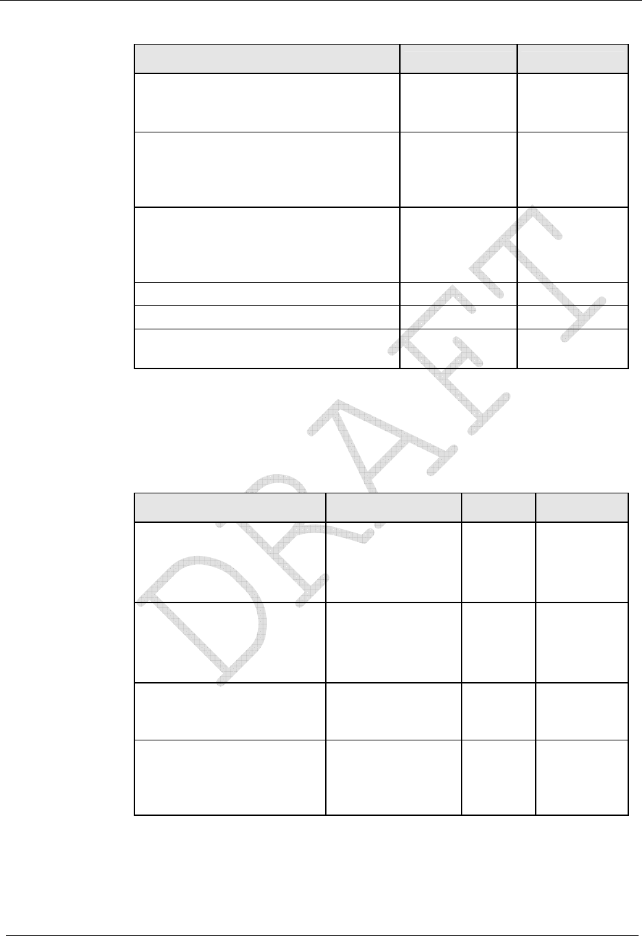
Operation: CP1SD/T/L Version
48 CENTRON® Polyphase Meter Technical Reference Guide
Measured Energy
Quantity Type Phases Directions
VA-hours (vectorial or arithmetic [RMS]) aggregate delivered
received
lagging
Volt-hours (Vh)
phase A
phase B
phase C
average
Amp-hours (Ah) phase A
phase B
phase C
V2h aggregate
A2h aggregate
Q-hours aggregate
delivered
received
Demand Registers
Demands can be calculated from any of the eight selected energy quantities. The user can
configure up to ten demand registers. The D/T/L Register can compute three types of
demand: Block Demand, Rolling Demand, or Thermal Demand.
Measured Demand
Quantity Type Demand Registers Phases Directions
watt-hours Block, Rolling,
Thermal aggregate
delivered
received
net
uni-
directional
Varhours Block, Rolling,
Thermal aggregate
delivered
received
net
per
quadrant
VA-hours (vectorial or
arithmetic [RMS]) Block, Rolling,
Thermal aggregate delivered
received
lagging
Amp-hours (Ah) Block
phase A
phase B
phase C
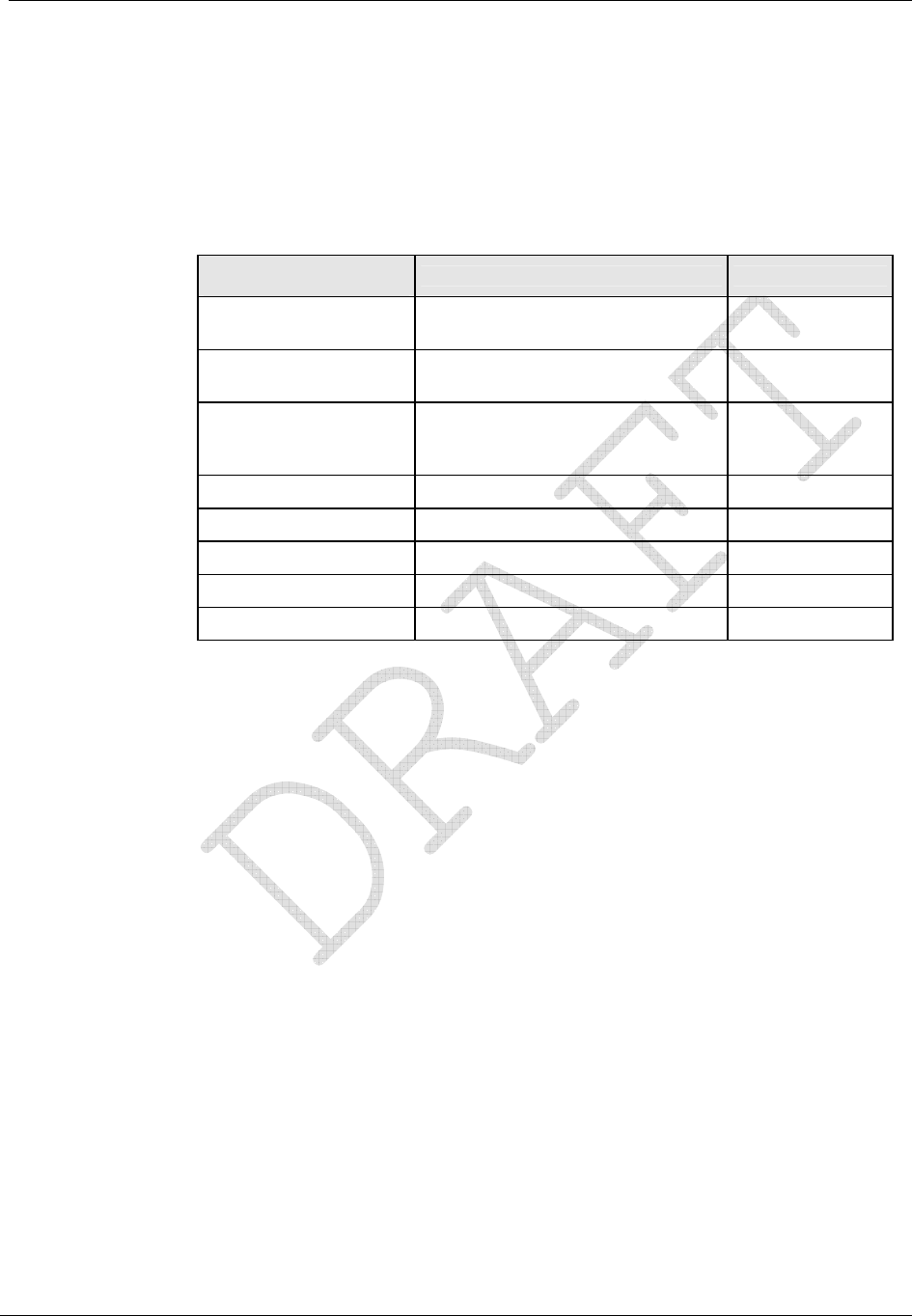
Operation: CP1SD/T/L Version
CENTRON® Polyphase Meter Technical Reference Guide 49
Instantaneous Registers
The D/T/L Register is capable of displaying Primary or Secondary Instantaneous registers,
with the following exceptions: Frequency, Power Factor (PF), and Phase Angles. The user
can configure the CT and VT multipliers (transformer ratios) using PC-PRO+ Advanced
programming software.
Instantaneous Register
Quantity Directions (Types) [Range] Phases
W Signed (+) Delivered or (-)
Received Aggregate
Var Signed (+) Delivered or (-)
Received Aggregate
VA
(Vectorial or
Arithmetic) None Aggregate
V None A, B, C
A None A, B, C
PF None Average
Frequency None A
Phase Angles Va = 0° Vb, Vc, Ia, Ib, Ic
Self Read and Snapshot Registers
There are up to fifteen self-read registers available in the D/T/L Register, depending on the
particular version. All meters have two snapshot registers that store self read data triggered
by a demand reset. Snapshot 1 is taken at the most recent demand reset. Snapshot 2 is the
next most recent set of self read data at demand reset. Meters with time keeping
functionality have an additional twelve self-reads registers used for scheduled self-reads,
and one Last Season self-read register triggered at a season change in TOU meters.
Information Registers
The D/T/L Register also stores a significant amount of informational data. These non-
registered values are listed in Informational Data.
Interrogation and Programming
Interrogation
The meter can be interrogated via the ANSI C12.18 optical port using PSEM (ANSI
C12.18-1996) protocol.

Operation: CP1SD/T/L Version
50 CENTRON® Polyphase Meter Technical Reference Guide
Programming
The software for programming this meter (PC-PRO+ Advanced) is a 32-bit Windows
NT/2000/XP application. User-definable security codes in both the programming software
and the meter prevent unauthorized access to the meter.
Programming and/or interrogation of the meter can be accomplished through the optical port
using a laptop PC and an optical probe.
Time-of-Use (TOU)
The Time-of-Use (TOU) functionality is designed for use in billing applications where
multiple rates (bins) are required for energy and demand. The TOU option provides 4 Rates
+ Total
TOU is a clock-dependent feature; therefore, a battery is required in the meter.
TOU Schedules
Schedule information is programmed using the PC-PRO+ Advanced Programming
software. The CENTRON Polyphase meter TOU calendar is programmable for up to 25
years and accommodates leap years, daylight savings time, and recurring holidays.
When using the TOU functions of the meter, energy and demand registrations are
segmented into time blocks during the day. Each time block is assigned one of four rate
periods. In addition to these four rate periods, a total rate is always available.
Calendar Schedule
The calendar schedule contains all daily and yearly information needed for the meter to
measure and register data in real time. The schedule contains daily patterns, seasons, and up
to 44 holidays with programmable day types, rates and outputs. For information concerning
the entry of these parameters into the PC-PRO+ Advanced software package, consult the
PC-PRO+ Advanced System Manual.
Rates
Four independent rates are available for TOU registration. These are designated A, B, C,
and D. Only one of these rates can be active at a time. The Total register, designated Rate
T, is always active, regardless of the active rate period. T
The D/T/L Register TOU rates are applied to all energy and demand registers that have been
selected for measurement. Therefore, all energy and demand registers are segmented as per
the TOU schedule and available in each rate period, in addition to the Total rate.

Operation: CP1SD/T/L Version
CENTRON® Polyphase Meter Technical Reference Guide 51
Daily Patterns
Each pattern defines the times during the day that rate period A, B, C, or D begins and ends.
Up to 24 rate period changes may be specified for each daily pattern.
Day Types
There are four day types: Weekday, Saturday, Sunday, and Holiday. Each day of the week
is assigned to one of the four day types. Each day type is assigned one of the four daily
patterns when each season is defined. Any of the daily patterns can be used in any
combination with the day types.
Seasonal Schedules
A season is a period of weeks during the year when a particular rate structure is in effect.
The year can be divided into a maximum of eight seasons. The day types with associated
daily patterns can be defined differently for each season. Up to eight season change dates
are specified for each year in the calendar schedule. If multiple seasons are not used, the
TOU schedule contains one year-round season.
Season changes occur at midnight of the season change date (where midnight corresponds to
00:00 hours) or can be designated through programming to occur at the first demand reset
following the season change date.
TOU Registers
The D/T/L Register can measure up to eight energies and ten demands. When the meter is
configured for a TOU calendar, all energies and demands that are selected for measurement
also have the configured TOU rates applied to them, with the exception of previous,
projected, and instantaneous registers. The TOU energy and demand registers are available
for display as well.
Current Season Registers
All energy and demand registers selected are considered current season registers. If a single
rate schedule is applicable year-round, then only current season registers are used.
Last Season Registers
Last season registers are available when two or more seasons are used during the year. For
every current season register (with the exception of Cumulative and Continuous Cumulative
registers), there is a last season register for the same quantity. Last season registers are
designated “LS” in the programming software. Last season registers can be selected for
display in Normal and Alternate Display Lists.
TOU Operation
This section describes TOU operation specific to the meter display. Several TOU indicators
are available on the liquid crystal display (LCD).

Operation: CP1SD/T/L Version
52 CENTRON® Polyphase Meter Technical Reference Guide
Rate Annunciators and Active Rate Indicators
Rate annunciators are available with each demand and energy register. An A, B, C, or D will
be displayed on the far right side of the LCD to indicate the rate period for each quantity
being displayed. The rate annunciator that may be displayed for the Total Rate is T. T
If the rate annunciator is flashing while a demand or energy value is displayed, the
annunciator indicates that it is the current rate in effect. This gives a quick indication that
the register is programmed with the correct TOU schedule and that it is currently set to the
correct time.
Season Change
At the end of a specified season, all last season registers are updated with current season
register data. The meter can be programmed to either delay the season change until a
demand reset occurs, to activate an automatic demand reset at season change, or to change
the season without performing a demand reset. A season change occurs at midnight at the
end of the programmed season change date or at the first demand reset following the season
change date, depending on how the meter has been programmed. Some utilities program the
season change to occur at the first demand reset following the season change date to make
season changes concurrent with the meter reading cycles.
The following events take place when an automatic demand reset occurs at a season change:
1 The current season energy registers are copied directly to the last season energy
registers.
2 The current season maximum demand registers are copied directly to the last season
maximum demand registers, and T rate is added to the cumulative demand register. T
3 After the demand reset, the maximum demand registers are reset to zero, and the T rate
cumulative demand register is copied to the last season cumulative demand register.
T
If there is no demand reset at season change, all current season registers are directly copied
to last season registers at season change, but no current season registers are zeroed.
Battery Carryover
When the meter recognizes a power outage, it begins battery carryover operations. Billing
data is transferred to non-volatile memory at this time, and all circuits, except the RAM and
timekeeping circuit, are de-energized. The timekeeping circuitry, powered by the lithium
battery, keeps time while the meter is in battery carryover mode.
Upon restoration of AC power, all self-diagnostics are completed, and data is retrieved from
non-volatile memory. The real time is retrieved from the real time clock. The elapsed time
of the outage is also added to the stored value for the time spent on battery.
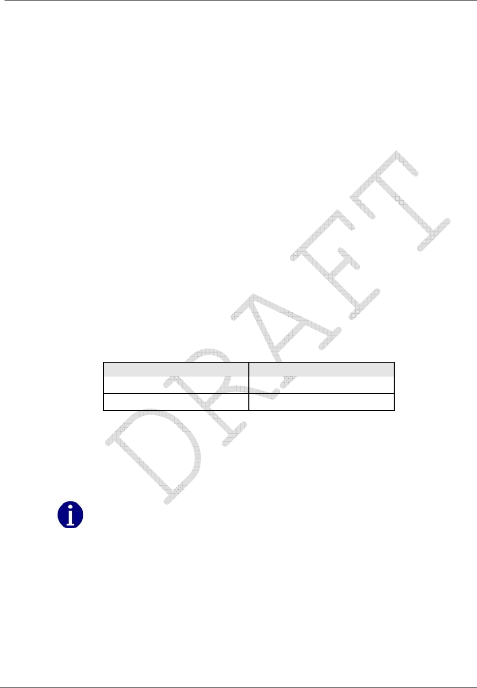
Operation: CP1SD/T/L Version
CENTRON® Polyphase Meter Technical Reference Guide 53
Load Profile
Load Profile (mass memory) data is stored in blocks (records) of 128 intervals. The profile
interval length is the same for all channels and is independent of the interval length for
demand quantities. Each interval of load profile data is identified by date and time. Each
interval contains status bits indicating the occurrence of outages, Test Mode, and other
significant events or errors. Refer to the PC-PRO+ Advanced online help for a list of Load
Profile Status Codes. Register readings are also stored for each channel for data validation.
The Load Profile functionality is designed for use in billing and load research applications
where multi-channel high resolution data is needed.
Load Profile Specifications
Capacity
The load profile option is available in 144 kBytes of memory. The amount of memory
actually used for load profile recording is programmable in 1 kByte increments. There are
up to 8 channels available for interval load profile data.
Bit Resolution
The load profile operates with 16-bit data resolution. Equivalent pulse count resolution is as
follows:
Bits Pulse Counts
16 65,535
15132,767
1 When a Net quantity (i.e., Net Wh) is chosen as a load profile channel, all load profile channels have
15-bit data resolution.
There is a difference between MV-90 and the D/T/L Register concerning load profile
data. The D/T/L Register can accommodate a maximum of 65,535 pulses (16 bit) per
interval. (A maximum of 32,767 pulses per interval is allowed when using bidirectional
quantities because the 16th bit is used for "+" or "-"). MV-90 is a 16 bit system,
however the 16th bit is always used for "+" or "-". Since the 16th bit is always signed,
the maximum allowed pulses per interval is always 32,767. If MV-90 receives a number
of pulses per interval larger than 32,767, MV-90 will record a negative number
(received value) for that interval.
Itron recommends programming any D/T/L Register with load profile that is
interrogated by MV-90 or any system that exports load profile information to MV-90 to
use 15 bit resolution or 32,767 pulses per interval.

Operation: CP1SD/T/L Version
54 CENTRON® Polyphase Meter Technical Reference Guide
Interval Lengths
The load profile records data on a block interval basis. The interval length is programmable
for 1, 2, 3, 4, 5, 6, 10, 12, 15, 20, 30, or 60 minutes. The interval length is the same for all
channels and is independent of the interval length for demand quantities.
Power Outage
The D/T/L Register flags an interval when a power outage exceeds a specified number of
seconds. The range for power outage length is programmable from 0 to 255 seconds and
must not exceed the programmed interval length.
During power outages the CENTRON Polyphase meter maintains all meter data as well
as timekeeping functions.
During an outage, billing data is stored in non-volatile memory.
When power is restored, data is returned to active memory and normal metering
resumes.
The meter records the date and time of the power outage and the power restoration (for
meters with batteries).
Channel Configuration
The D/T/L Register can be programmed to have one to eight channels of interval load
profile data. Each channel corresponds to an energy register selected during the
programming process. In order to load profile an energy, the energy must first be selected
as a quantity to be measured.
Selection of channel configuration and pulse constants is accomplished through the
programming software. Each data channel is programmed to record load profile data from a
user-selected register. The energy registers allowed for load profile are listed in Energy
Data.
Pulse Constants
For each load profile channel, the pulse constant is programmable from 0.01 to 10 unit
hours per pulse in 0.01 increments. The load profile pulse constants apply to secondary
readings only.
Example: Calculation of pulse weight from kWh
A meter, 3-element, 120 Volts, CL20 is programmed to record kWh in load profile with 15
minute intervals.
First, calculate the maximum watthour accumulation during 15 minute intervals:
)25.0()3()20()120(max hoursXphasesXAXVWh =
watthoursWh 800,1max =

Operation: CP1SD/T/L Version
CENTRON® Polyphase Meter Technical Reference Guide 55
The maximum number of pulses is 65,535; therefore, the smallest pulse weight (PW) that
can be used is:
0275.0
535,65
1800
min == Wh
PW
Since the pulse weight value must be a multiple of 0.01 in the meter, 0.03 Wh could be
programmed as the pulse weight (Ke) for the kWh channel in load profile in this example.
Data Storage
The D/T/L Register uses non-volatile flash memory to record load profile data. Data is
stored in load profile memory at the end of each interval. Each channel has 16 bits written to
load profile memory. For example, consider 8 channels of load profile. At the end of an
interval, a 16-bit number is written into load profile memory for channel 1; a 16-bit number
for channel 2 follows immediately; and so on, up to the last 16-bit number for channel 8,
which follows immediately.
The process continues for each interval until 128 intervals (one block or record) have been
recorded. In addition to the profile data, each interval contains eight types of status bits
written into each data interval.
1 Partial Interval—The status bit is set for a partial interval due to a time adjust, power
outage, or beginning interval.
2 Long Interval—The status bit is set for a long interval due to a time adjust backwards.
3 Skipped Interval—The status bit is set for a skipped interval due to either a power
outage, Test Mode, or time adjusted forward during the interval.
4 Test Mode—The status bit is set for Test Mode due to the meter being in test mode
during the interval.
5 DST—The status bit is set for DST due to DST being in effect during the interval.
6 Power Outage—The status bit is set for each interval during which a power outage
occurs (greater than the minimum time programmed in software).
7 Time Adjust Forward—The status bit is set for time adjust forward during the
interval.
8 Time Adjust Backward—The status bit is set for time adjust backward during the
interval.
Refer to the PC-PRO+ Advanced online help for a list of Load Profile Status Codes.
In addition to the interval profile data and the interval status data, each block contains a time
tag specifying the month, day, hour, and second of the end of the data block.
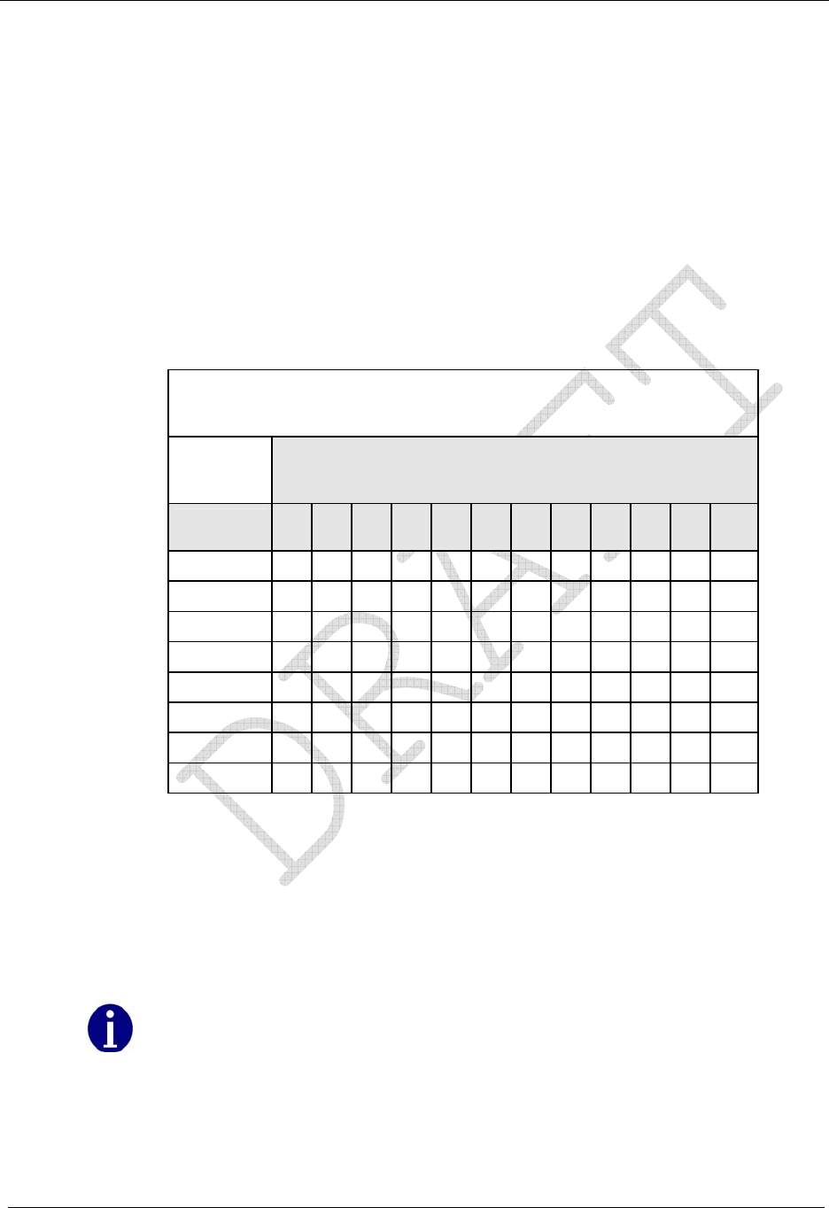
Operation: CP1SD/T/L Version
56 CENTRON® Polyphase Meter Technical Reference Guide
Recording Duration
The following equation can be used to determine the recording duration of the load profile:
Recording Duration (days) = (M x I x 1024) / (1,440 x [(2 x C + 2) + ((6 x C + 4) / 128)])
M = Memory size in kilobytes
C = Number of channels
I = Interval Length in minutes
The tables below show the recording duration for 144 kilobytes (KB) load profile memory
size.
Recording Duration (in days) for 144 KB of Load Profile Memory
INTERVAL LENGTH (Minutes)
Number of
Channels 1 2 3 4 5 6 10 12 15 20 30 60
1 25 50 75 100 125 150 251 301 376 502 753 1506
2 16 33 50 66 83 100 167 200 250 334 501 1003
3 12 25 37 50 62 75 125 150 187 250 375 751
4 10 20 30 40 50 60 100 120 150 200 300 601
5 8 16 25 33 41 50 83 100 125 166 250 500
6 7 14 21 28 35 42 71 85 107 143 214 429
7 6 12 18 25 31 37 62 75 93 125 187 375
8 5 11 16 22 27 33 55 66 83 111 166 333
Event Log
The D/T/L Register has an Event Log that records historical events that have taken place in
the meter. The events to be logged must be configured via the PC-PRO+ Advanced
programming software. To aid in troubleshooting, Itron recommends enabling all events to
be logged.
In order to have date and time associated with an event, Time-of-Use or Load Profile
is required. A Demand-only D/T/L Register allows for event log recording. However,
in the event of a power outage, the date and time will not be reliable.
The D/T/L Register Event Log is circular in nature, allowing for the capture of the most
recent events in the meter at all times. The CENTRON Polyphase meter is capable of
retaining 420 events prior to wrapping.

Operation: CP1SD/T/L Version
CENTRON® Polyphase Meter Technical Reference Guide 57
Each event log record includes an event description, a time and date stamp, and additional
information on certain events.
For meters with batteries, all logged events are retained through a power outage. For meters
without batteries, the Event Log is periodically written to non-volatile memory. Events that
occur just prior to a power outage may be lost depending on whether they were backed-up
or not.
The contents of the event log can be viewed using the meter programming software.
The following events may be configured for recording in the D/T/L Register Event Log:
Clear Billing Data—billing data has been cleared upon initialization of the meter, or as
a secondary activity by authorized personnel
Configuration Error—meter configuration was not successful
Demand Reset—a demand reset occurred
Diagnostic 1 On—diagnostic 1 condition occurred
Diagnostic 1 Off—diagnostic 1 condition went away
Diagnostic 2 On—diagnostic 2 condition occurred
Diagnostic 2 Off—diagnostic 2 condition went away
Diagnostic 3 On—diagnostic 3 condition occurred
Diagnostic 3 Off—diagnostic 3 condition went away
Diagnostic 4 On—diagnostic 4 condition occurred
Diagnostic 4 Off—diagnostic 4 condition went away
Diagnostic 5 On—diagnostic 5 condition occurred
Diagnostic 5 Off—diagnostic 5 condition went away
DST Time Change—DST adjustment forward or backward has occurred
Event Log Cleared—Event Log was cleared by programming software
Full Scale Overflow—see Non-fatal Error 6 for description
Load Profile Error—see Non-fatal Error 5 for description
Logon Successful—a user or option board logged on successfully to the meter
Loss of Phase—see Non-fatal Error 2 for description
Loss of Phase Restored—phase voltage was restored
Low Battery—see Non-fatal Error 1 for description
Meter Reprogrammed—meter was initialized or reconfigured
Power Outage—power was lost
Power Restored—power was restored
Rate Change—TOU rate change occurred
Register Self Read—self read occurred
Reverse Power Flow—see Non-fatal Error 4 for description
Reverse Power Flow Restored—delivered power flow resumed after reverse flow
exceeded a configured threshold
Season Change—TOU season change occurred
Security Fail—logon with security code failed
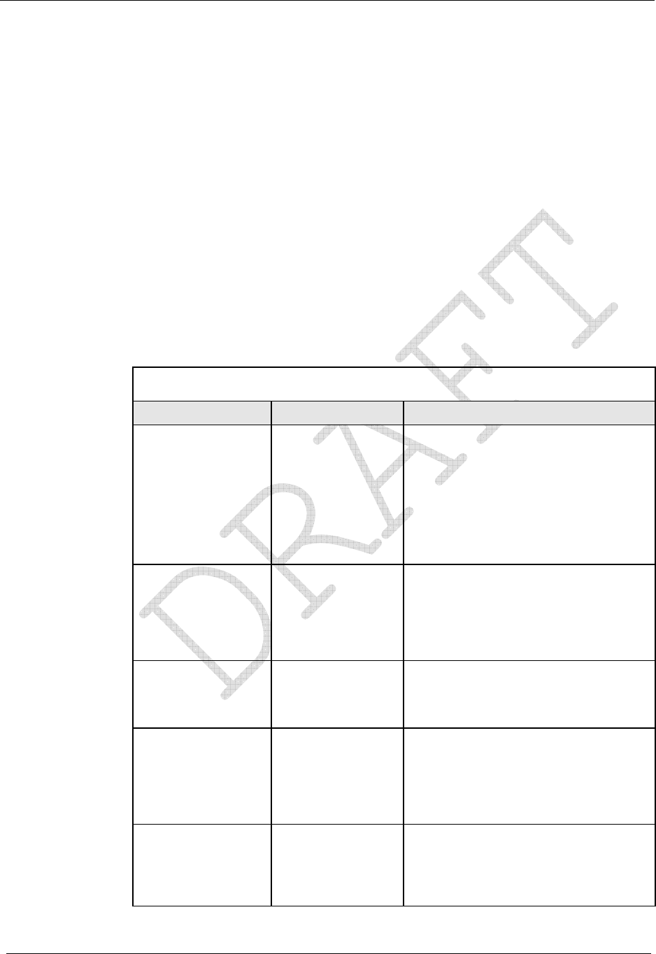
Operation: CP1SD/T/L Version
58 CENTRON® Polyphase Meter Technical Reference Guide
Security Pass—logon with security code succeeded
SiteScan Error—a SiteScan error occurred
Test Mode Entered—Test Mode or Alternate Test Mode was entered
Test Mode Exited—Test Mode or Alternate Test Mode was exited
Time Changed—a time adjustment forward or backward occurred
TOU Schedule Error—see Non-fatal Error 3 for description
Security Codes
The meter security codes provide protection for meter register and load profile data. Four
levels of security are inherent in the D/T/L Register. The table below describes the level of
access to the meter provided by each device security code. Once security codes are
programmed and stored in the meter, users are required to logon to the meter with an
appropriate password. The user may choose not to use security codes in the meter’s
program.
D/T/L Register Security Code Levels
Level Access Level Description
Primary/Firmware
Download Read/Write
access and
firmware
download
Access to the meter is unrestricted. All
read/write functions are available
including all programming options, the
ability to download new firmware to the
meter, and upgrade or downgrade
MeterKey™ features. New security
codes can be programmed into the
meter using the level of access
provided by this security code.
Limited
Reconfigure Read/Limited
Write access Provides read and limited write access
including the ability to reset demand,
change the time in the device, and
reconfigure the device. You cannot
clear billing data, change display
modes, or change security codes.
Secondary Read-only access
plus Demand
Reset and Reset
Time
Read-only access is provided as well as
the ability to reset demand and change
the time.
Tertiary Read-only access Access to the meter is limited to reading
information from the meter. No
operation that writes information to the
meter is available. This code can be
used by other applications that contact
the meter.
Previous Security
Code Read-only access This code is not programmed into the
meter; it allows a user to save an
alternate password in the software to
use for logging on only; can be any
security level.

Operation: CP1SD/T/L Version
CENTRON® Polyphase Meter Technical Reference Guide 59
Implementing Security Codes
When a customer file is created, security codes are entered by the software (PC-PRO+
Advanced) operator. Each security code may be from 1 to 20 characters long. For example,
the primary code is selected to be ABC and the secondary code is to be 123. When the
software first attempts to communicate with a meter that has just been delivered from the
factory, the meter has only null security codes. The software downloads and unlocks the
meter with these null security codes. When the meter is initialized, the software downloads
security codes ABC and 123 to the meter.
When unlocking a meter with security codes, the software downloads the primary code that
is in the PC-PRO+ Advanced Device Security Codes dialog— in this case ABC. If this code
matches the meter primary code, the operator can read and/or program the meter. If it does
not match the primary, but matches the secondary, 123, the operator can only read data from
the meter.
For example:
Three PCs are set up to interrogate D/T/L Registers. One PC is designated as the Master PC.
The Master PC programs D/T/L Registers for installation and interrogates meters in the
field. In this example, the Master PC programs a meter with a primary security code of
SEN1 and a secondary security code of 222. The Master PC can then read data from and
reprogram the meter. The remaining two PCs are configured so that the same customers are
in each database, but each PC-PRO+ Advanced software is configured with a security code
that matches the meter’s secondary security code only. In this case, the two additional PCs
have been given security code 222. When the two PCs interrogate the meter, the security
code they download provides them with secondary security code privileges only.
To set up a meter so that the Master PC can perform all meter functions, but any other PC
has limited access, program the meter through the Master PC with a primary security code,
but leave the secondary security code blank. Any PC other than the Master PC will connect
to the meter using a blank security code and thereby gain secondary access only.
Clearing Security Codes
To clear the existing security codes in the meter, perform a Factory Reset.
If security codes are cleared from the meter in this manner, the PC will have no record of a
security code change. The PC will go through the following attempts to gain access to the
meter:
If the Options | Default Values | Device Security Codes | Override Security Code
menu option IS NOT checked, PC-PRO+ Advanced will:
Use the security code in the device Primary field.
Use the security code in the device Previous Security Code field.
Use all nulls.
If the Options | Default Values | Device Security Codes | Override Security Code
menu option IS checked, PC-PRO+ Advanced will:
Use the security code entered in the Security Code field on the logon screen.

Operation: CP1SD/T/L Version
60 CENTRON® Polyphase Meter Technical Reference Guide
Use the security code in the device Previous Security Code field.
Use all nulls.
Firmware Upgrades
PC-PRO+ Advanced 7.2 and higher supports upgrading firmware for D/T/L Registers.
When the firmware is upgraded, all billing data in the D/T/L Register is erased. After a
D/T/L Register’s firmware is upgraded, you must re-initialize the meter.
You can determine which version of D/T/L Register firmware is installed on your PC by
looking at Add/Remove Programs in the Control Panel (Start | Settings | Control Panel) and
reading the Support Information for the D/T/L Register firmware. The firmware version is
also displayed each time you begin a firmware upgrade while logged on to a D/T/L Register.
This feature is not available for meters that have been initialized (sealed) for
Canadian installations. If a Canadian meter has not been sealed, the firmware can be
upgraded.
Installing D/T/L Register Firmware on the PC
You must install the D/T/L Register firmware on your computer to make it available to
PC-PRO+ Advanced. You can obtain firmware upgrades through your Itron, Inc. Sales
Representative. You can install only one version of D/T/L Register firmware on a computer.
For more information, refer to your PC-PRO+ Advanced online help files and the
PC-PRO+ Advanced CENTRON Device Online User’s Manual.
After you have installed the D/T/L Register firmware on your computer, if you attempt to
initialize a D/T/L Register that has a different version of firmware, a message is displayed
stating that the firmware in the meter is different and asks if you want to change the meter
firmware.
R300 Series
As an option the D/T/L register can be ordered with R300 functionality. The R300
continuously transmits Standard Consumption Messages (SCM) and Interval Data
Messaging (IDM) using radio frequency in the unlicensed frequency band which can be
read by handheld, drive-by or fixed network systems. The table below describes the various
versions of the R300 option:
Option SCM ERT Type IDM Type Description
R300CD (HP/LP) 04 N/A Two ERT register w/o
IDM
R300CD3 (HP/LP) 08 25 Three ERT register w/
IDM

Operation: CP1SD/T/L Version
CENTRON® Polyphase Meter Technical Reference Guide 61
Each SCM message contains tamper information. Below is a chart that indicates the tamper
information available in each SCM:
SCM # Indicator # Group
1 1 Meter Inversion
1 2 Meter Removal
2 1 Demand Reset (Push Button)
2 2 Low Battery or End of Billing Schedule (1 Year from end)
Warning
3 1 Billing Events
3 2 Non-Billing Warnings
Using the PC-PRO+ Advanced programming software, you can:
Configure the quantity(s) to be transmitted
Select the type of registers to be transmitted.
Select the number of digits for the data to be transmitted as well as the number of
decimal place digits for the data.
Select the type of registers to be transmitted.
Select the number of digits for the data to be transmitted as well as the number of
decimal place digits for the data.
Select one of three date formats to be transmitted as ERT information.
Enable TOU and select the TOU rate to be transmitted.
Select whether transmission shall be stopped based on SiteScan
When using Type 8 ERTs the format for the kWH value should be 7.0(XXXXXXX)
and the format for the Demand value should be 7.3 (XXXX.XXX).
SiteScan On-Site Monitoring System
The SiteScan on-site monitoring system consists of the following features:
Meter self-diagnostic checks
Toolbox Mode with its on-site and/or on-line display
SiteScan system and installation diagnostic checks
Diagnostic output alarms
Using the Itron, Inc. PC-PRO+ Advanced Programming software package you can
customize the SiteScan System for each individual metering site. The use of the SiteScan
on-site monitoring system greatly enhances the ability to diagnose and resolve site-specific
metering or tampering problems.
Operation: CP1SD/T/L Version
62 CENTRON® Polyphase Meter Technical Reference Guide
SiteScan Meter Self-Diagnostic Checks
The CENTRON Polyphase meter performs self-diagnostic checks to confirm proper meter
operation. The following is a list of possible errors and associated error codes:
Error Error Type Error Code
Flash Error Fatal Error FAtError1
RAM Error Fatal Error FAtError2
Data Flash Error Fatal Error FAtError3
CPC/Metrology Error Fatal Error FAtError4
Power Down Error Fatal Error FAtError5
Low Battery Error Non-Fatal Error ERR1-----
Loss of Phase Voltage Error Non-Fatal Error ERR-2----
TOU Schedule Error Non-Fatal Error ERR--3---
Reverse Power Flow Error Non-Fatal Error ERR---4--
Load Profile Error Non-Fatal Error ERR----5-
Fullscale Exceeded Non-Fatal Error ERR-----6
Valid Service Not Found (SiteScan Error) Non-Fatal Error ERR--9---
Diagnostics 1 Diagnostic diA 1-----
Diagnostics 2 Diagnostic diA -2----
Diagnostics 3 Diagnostic diA --3---
Diagnostics 4 Diagnostic diA ---4--
Diagnostics 5 Diagnostic diA ----5-
A fatal error indicates an internal meter problem, which ceases all meter functions except
communications. These errors cause the display to lock on the error code until the meter is
re-initialized.
The non-fatal errors can indicate either a meter problem such as low battery error or a site
problem such as the loss of phase voltage error. The non-fatal self-diagnostic checks can be
independently enabled or disabled through the PC-PRO+ Advanced software.
SiteScan Toolbox Mode
SiteScan Toolbox Mode displays all the metering information used by the meter for
individual phase measurements and system and installation diagnostic checks. This
information helps the user verify that the meter is installed and operating correctly. The per-
phase RMS voltage and current readings along with both voltage and current angle readings
let the user check the meter’s site phase sequencing performance. The diagnostic counters
alert the user to the frequency of a metering installation or tampering problem. The
combination of a diagnostic error and the information in the Toolbox Mode display will
greatly enhance the ability to diagnose and resolve metering or tampering issues.
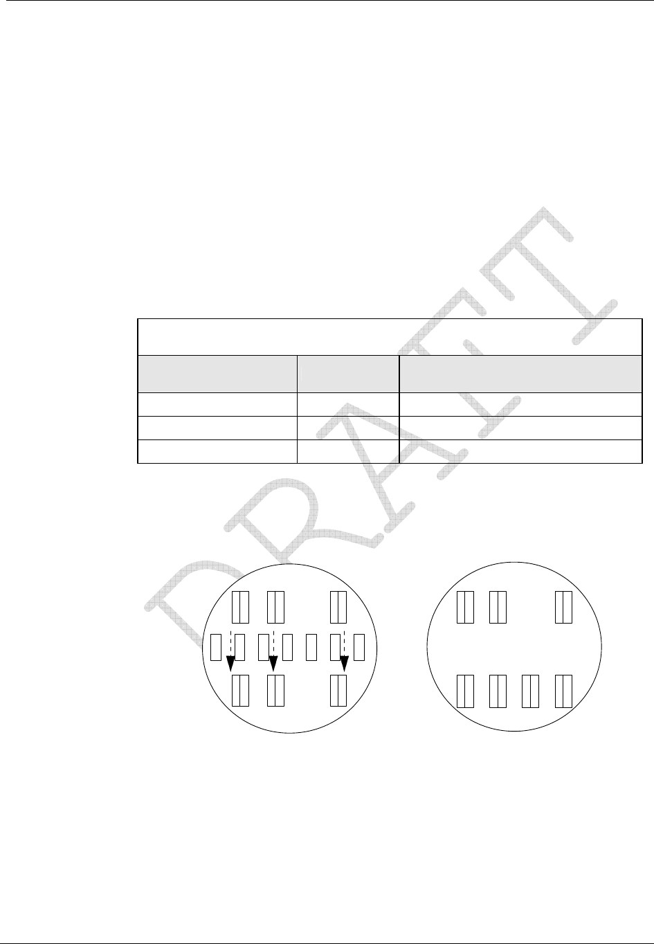
Operation: CP1SD/T/L Version
CENTRON® Polyphase Meter Technical Reference Guide 63
The PC-PRO+ Advanced software lets the user retrieve Toolbox information (the same
information available by accessing the display list through the use of a magnet and magnetic
switch) on an instantaneous basis with a graphical vector diagram.
To best understand the values on the Toolbox display, one should graphically plot this
information. Before starting to manually plot the Toolbox data, two basic definitions must
be understood about the SiteScan system.
Definition 1: The per-phase information displayed in the Toolbox Mode is
referenced to the internal voltage and current sensors of the meter.
The meter will designate each phase by the elements. The table
below defines each element.
Phase Notation in Display
Element Used in Meter Defined Phase Phase Notation in Toolbox Display
Left-hand Element Phase A PhA
Center Element Phase B PhB
Right-hand Element Phase C PhC
The figure below shows how the wiring of each element determines the phase notation used
by the meter. (socket view)
IAIBIC
VAVBVC
N
Form 9S Form 16S
IAIBIC
VAVBVC
N
Figure 25: Toolbox Phase Notation for Form 9S and 16S CENTRON Polyphase Meters
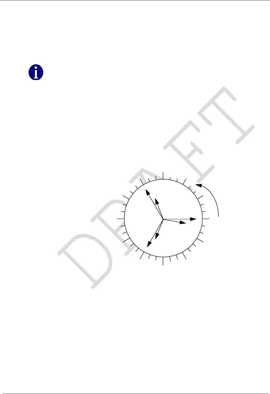
Operation: CP1SD/T/L Version
64 CENTRON® Polyphase Meter Technical Reference Guide
Definition 2: The SiteScan system uses the A phase voltage as a reference point.
Therefore, the Toolbox Mode display of the A phase voltage angle will
always be 0.0°V. The CENTRON Polyphase meter is still determining
this angle and will still detect a problem if the A phase voltage angle is
incorrect.
A phase angle variations will manifest as errors in the other phases.
After the meter sets the A phase voltage direction to 0.0 degrees, the meter calculates all the
other voltage and current angles relative to the A phase voltage. This allows the user to
easily plot the vector information, not only to determine problems, but also to determine the
phase sequencing of the site.
The figure below provides an example of the plot for Toolbox Mode information. No matter
how the phasor information is plotted, whether the user plots the same as shown in the
figure below or in the opposite direction with 90° at the 12 o’clock position, the Toolbox
Mode will still provide an accurate representation of the site.
270
VA
IA
VB
IB
VC
IC
0
180
90
Figure 26: Plot of Toolbox Display Mode
In this example, the plot is going in the clockwise direction. Therefore, the phasors will be
rotating in the counterclockwise direction. By using this information, the phase sequencing
of the meter site can be determined. In the case shown, the A phase voltage is seen first. The
next voltage phasor is B phase and last is C phase voltage, indicating ABC rotation. For
CBA rotation, A phase voltage at zero will be seen first, but the user would see C phase
voltage next followed by B phase.

Operation: CP1SD/T/L Version
CENTRON® Polyphase Meter Technical Reference Guide 65
The following is an example of the data available in the Toolbox Mode. This example is for
a Form 9S meter wired for a 4-Wire Wye system:
Phase A Display
(Left Element) Phase B Display
(Center Element) Phase C Display
(Right Element)
Voltage Phase
Angles PhA 0.0° V PhB 120.5° V PhC 240.3° V
Phase Voltage PhA 120.2 V PhB 115.5 V PhC 119.3 V
Current Phase
Angles PhA 9.0° A PhB 117.8° A PhC 246.0° A
Phase Current PhA 6.8 A PhB 10.2 A PhC 9.8 A
Diagnostic Counters1 d1 000 d2 000 d3 000 d4 000
d5A 000 d5B 000 d5C 000 d5T 000
1 The diagnostic counters are incremented each time a diagnostic error occurs.
If the magnitude of a phase voltage or current is zero or too low to measure accurately, a
dashed line (---) will appear in the value location. The corresponding angle will also indicate
dashed lines. Accurate measurement is considered to be 0.5% of class rating for the current:
CL 20 = 10 mA
CL 200 = 1 Amp
CL 320 = 1.6 Amps
By following the definitions of the SiteScan system and the information on the Toolbox
display, the above example can be graphically plotted into the phasor diagram shown in the
figure above.
By simply viewing the phasor diagram, several facts about the site become clear:
There are no wiring problems currently at the site.
Both A and C phase currents lag while B phase current leads its voltage.
The site is wired with ABC phase rotation.
By graphically plotting the Toolbox Mode display information, many metering site
problems are easily diagnosed. Problems such as cross-phasing of voltage or current
circuits, incorrect polarity of voltage or current circuits, and reverse energy flow of one or
more phases can be found quickly. The load emulator scrolling in the direction of energy
flow for each phase will also aid in checking for reverse energy flow. Other problems, such
as loss of phase voltage, incorrect voltage transformer ratio, current diversion, or a shorted
current transformer circuit, can be determined through the Toolbox Mode.
While some of these problems may occur at the time of meter installation, others may
happen at any time after the meter is installed. Since it is impossible to continuously watch
the Toolbox Mode information, the SiteScan on-site monitoring system has been designed
to continuously monitor the site. The occurrence of any diagnostic condition can be logged,
as well as display error codes on the LCD.

Operation: CP1SD/T/L Version
66 CENTRON® Polyphase Meter Technical Reference Guide
SiteScan System and Installation Diagnostic Checks
The SiteScan on-site monitoring system has the ability to continuously monitor the site for
metering installation or tampering problems through the system and installation diagnostic
checks. The following software programmable diagnostic checks are available:
SiteScan Diagnostic #1 Cross-Phase, Polarity & Energy Flow Check—This diagnostic
verifies that all meter elements are sensing and receiving the
correct voltage and current angles for each phase of a specific
polyphase electric service. The limits are +/- 10 degrees for
voltage and +/- 90 degrees for current.
SiteScan Diagnostic #2 Phase Voltage Deviation Check—This diagnostic verifies that
each individual phase maintains an acceptable voltage level
with respect to the other phases. Problems such as shorted
potential transformer windings, incorrect phase voltage, and
loss of phase potential among others may be indicated.
SiteScan Diagnostic #3 Inactive Phase Current Check—This diagnostic verifies that
each individual current phase maintains an acceptable current
level. It may indicate problems such as current diversion and
open or shorted circuits, among others.
SiteScan Diagnostic #4 Phase Angle Displacement Check—Similar to Diagnostic 1,
but this diagnostic allows the user to define an acceptable
angle displacement between the phase voltage and current.
This diagnostic may indicate problems such as poor load
power factor conditions, poor system conditions, or
malfunctioning system equipment.
SiteScan Diagnostic #5 Current Waveform Distortion Check—This diagnostic detects
the presence of direct current (DC) on any of the phases of the
meter.
It is very important to note that the meter will continue to operate normally while any of the
diagnostic errors are being displayed. The system and installation diagnostic checks will
only report that there may be a problem with the site. They have no effect on metering or on
any operations performed by the CENTRON Polyphase meter.
If enabled, all the diagnostic checks will continually check for errors every five seconds.
The CENTRON Polyphase meter will not check for diagnostic errors under any of the
following conditions:
When single phase series conditions occur (Test Bench)
When the meter is in Test Mode
When the diagnostic(s) have been disabled by the programming software
When auto service sense is configured the meter cannot determine the service type

Operation: CP1SD/T/L Version
CENTRON® Polyphase Meter Technical Reference Guide 67
The system reports diagnostic errors in several ways. If a diagnostic check is enabled and an
error occurs, the system will always increment the corresponding diagnostic counter by one.
The range for all diagnostic counters is from 0 to 255. When the counter reaches 255, it
remains there until it is reset by the user. The diagnostic checks will continue to function
and report any errors even after the diagnostic counter has reached 255. The PC-PRO+
Advanced programming software can be used to reset the counters. Refer to the PC-PRO+
Advanced documentation for instructions on how to reset the counters.
The system can also be programmed to display diagnostic errors similar to the one shown in
the figure below.
Need New Photo...
If more than one diagnostic error condition exists, the meter will display a combined error
message. Diagnostic errors will not be shown if any fatal or non-fatal errors are displayed.
Each of the diagnostic checks can be independently programmed with one of the following
display options:
Disable The diagnostic error will not be displayed on the meter display
or increment the diagnostic counter.
Ignore The diagnostic error will not be displayed on the meter.
However, the diagnostic error will still increment the diagnostic
counter. This option can be used to determine the frequency of
an error without reporting it on the display of the CENTRON
Polyphase meter.
Lock The diagnostic error is locked on the display.
Activating the magnetic switch for more than 4 seconds to select
Normal, Alternate, or Toolbox display mode will cause the meter
to scroll through that list and then lock again on the error.
Scroll The diagnostic error will be displayed during the “Off Time”
between display items. When an error occurs, the meter will
display the error during the next and all subsequent “Off Time”
of the current display mode (Normal, Alternate, or Toolbox).
The meter will check for all enabled diagnostic errors every five seconds. If three
consecutive checks fail, the meter will flag the error. Therefore the meter takes
approximately 15 seconds before an error is flagged. A diagnostic error may take longer to
display on the meter depending on the display option chosen. Once the condition causing
the error is corrected, the meter must pass two consecutive checks before the diagnostic
error is cleared from the display.
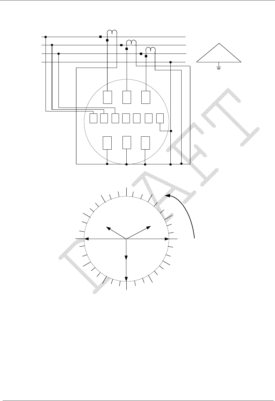
Operation: CP1SD/T/L Version
68 CENTRON® Polyphase Meter Technical Reference Guide
IAIBIC
A
B
C
Line Load
270
0180
90
Ic
Vc
IA
VA
A
C
210
B
NN
IB
VAVCNVB
VB(CBA Rotation)
Expected vector diagram at unity power factor with load connected line-to-neutral
330
Figure 27: Form 9S CENTRON Polyphase Meter 4-Wire Delta Phasor Diagram
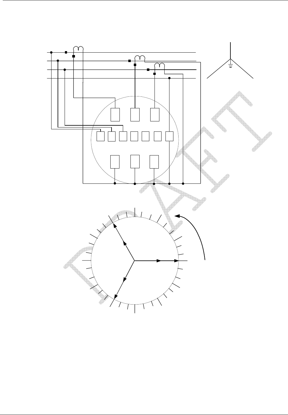
Operation: CP1SD/T/L Version
CENTRON® Polyphase Meter Technical Reference Guide 69
B
I
A
I
B
I
C
270
0180
90
I
c
Vc
I
A
V
A
A
B
C
Line Load
AC
240
N
N
I
B
120
V
A
V
C
NV
B
(ABC Rotation)
V
B
Figure 28: Form 9S CENTRON Polyphase Meter 4-Wire Wye Phasor Diagram
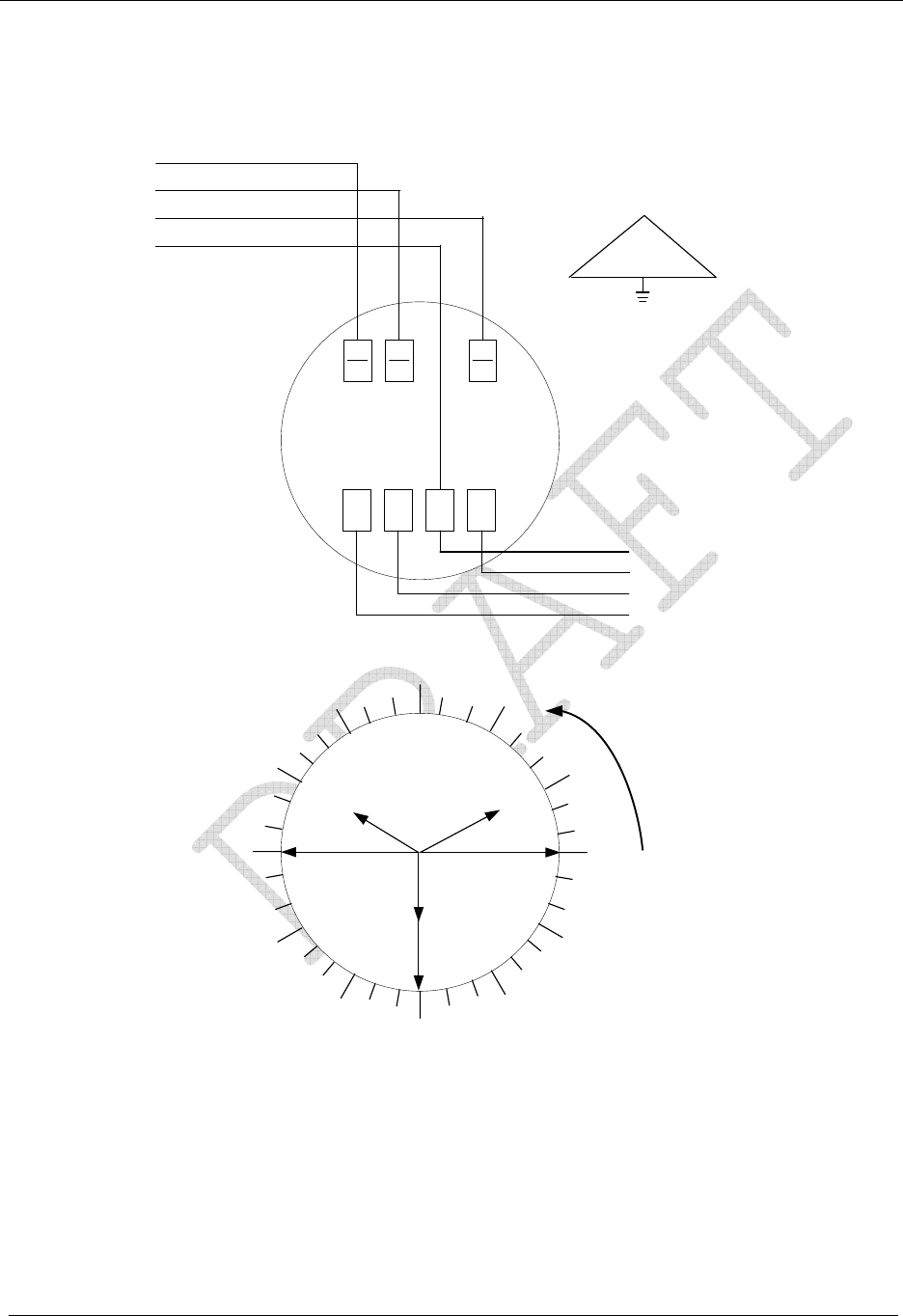
Operation: CP1SD/T/L Version
70 CENTRON® Polyphase Meter Technical Reference Guide
I
A
V
A
I
B
V
B
I
C
V
c
N
A
B
C
Line
Load
N
A
C
B
A
B
C
N
270
0180
90
I
c
Vc
I
A
V
A
210
I
B
V
B
(CBA Rotation)
330
N
Figure 29: Form 16S CENTRON Polyphase Meter 4-Wire Delta Phasor Diagram
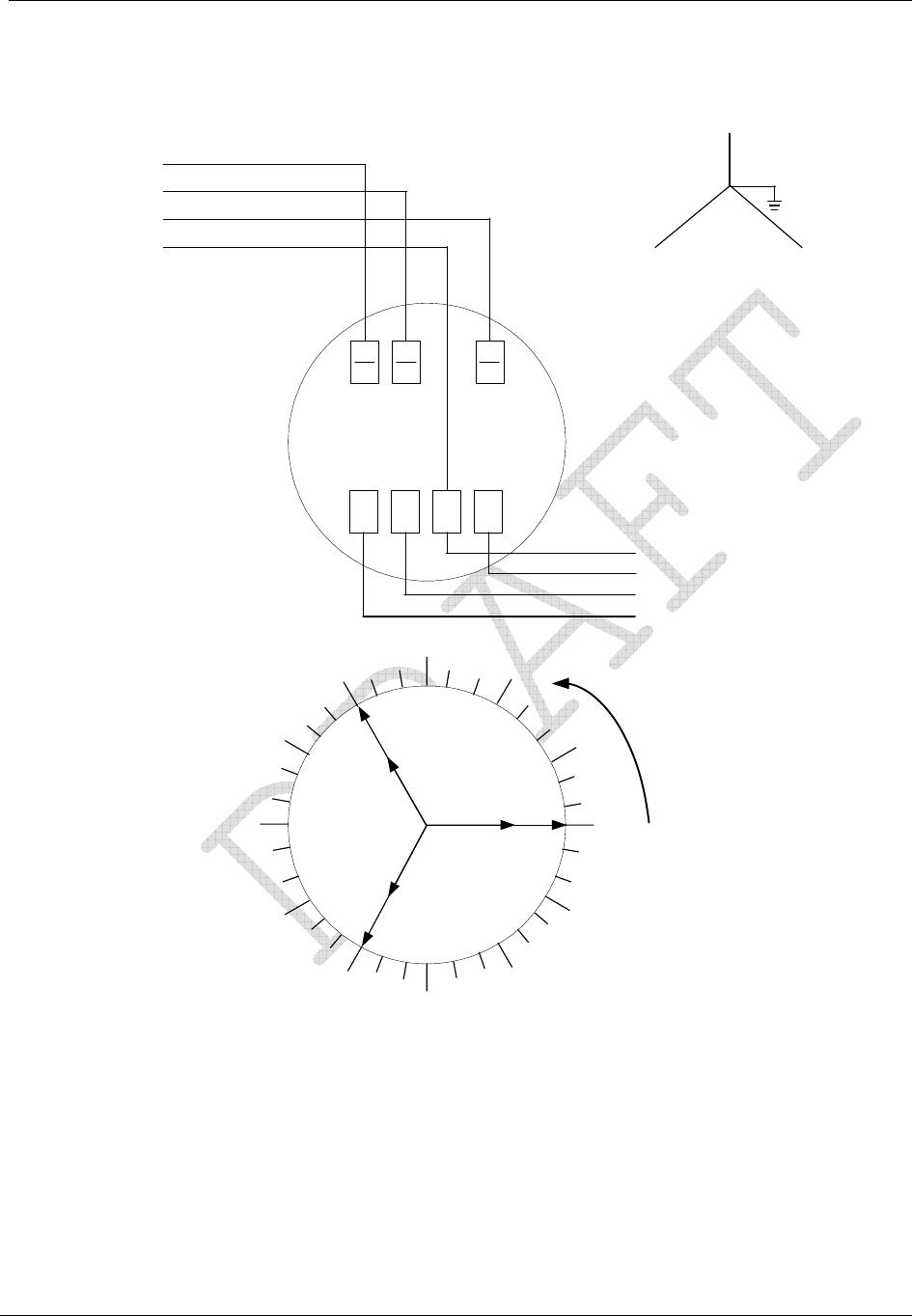
Operation: CP1SD/T/L Version
CENTRON® Polyphase Meter Technical Reference Guide 71
I
A
V
A
I
B
V
B
I
C
V
c
N
270
0180
90
I
c
Vc
I
A
V
A
120
Expected vector diagram at unity power factor with load connected phase-to-neutral
A
B
C
Line
Load
AC
240
B
N
N
A
B
C
N
V
B
I
B
(ABC Rotation)
Figure 30: Form 16S CENTRON Polyphase Meter 4-Wire Wye Phasor Diagram

Operation: CP1SD/T/L Version
72 CENTRON® Polyphase Meter Technical Reference Guide
SiteScan Diagnostic #1
The purpose of this diagnostic is to verify that all meter elements are sensing and receiving
the correct voltage and current for each phase. This diagnostic may indicate one or more of
the following problems:
Cross-phasing of a voltage or current phasing
Incorrect polarity of a voltage or current circuit
Reverse energy flow of one or more phases
Internal meter measurement malfunction
Faulty site wiring
This error will not be reported when the meter is in a serial test configuration since this is
considered as a “valid” 3-element 4-wire Y service.
The voltage and current angles are determined with respect to phase A voltage, and
compared to a pre-established service diagram, according to the current meter service in use.
A lag and lead tolerance is entered as a parameter for the current and voltage angles.
Current Angle Tolerance
The SiteScan Current Angle Tolerance configurations in PC-PRO+ Advanced are the lead
and lag tolerances for current angles associated with Diagnostic #1. The range of adjustment
is from 90 to 120 degrees both lag and lead direction.
Cross-Phase, Polarity, and Energy Flow Check
Although the diagnostic checks occur every 5 seconds, once every second the meter
determines the angle of each voltage and current phasor with respect to VA. The meter will
not only display this information in the Toolbox Mode, but will determine each phasor angle
for validity with respect to the meter’s form and service type. Diagnostic #1 will take the
“typical” phasor diagram for a particular form number and service type and place an
envelope around each phasor where the actual phasor must be found for the diagnostic
check to pass. The envelope for the voltage vectors is fixed at ±10° and the envelope for the
current vectors is fixed at ±100°. The meter will recognize ABC or CBA phase rotation and
will adjust the SiteScan expected values.
For example, if a typical diagram has the B phase voltage angle at 120°, and the envelope
around that phasor is ±10°, then the actual phasor must be between 110° to 130° from VA
for the diagnostic check to pass. The system will check each phasor in a similar fashion. The
system will define the phasor envelope for each phase.
Figure 7.4 through Figure 7.13 show the ideal phasor diagrams for all possible form
numbers and service types. These vector relationships assume site wiring as shown and the
special case of unity power factor with balanced phase loading.
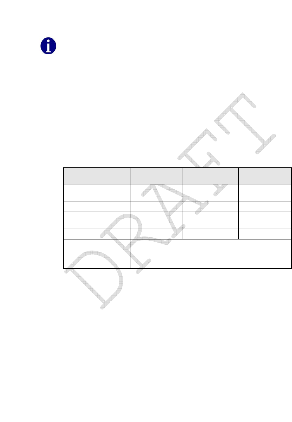
Operation: CP1SD/T/L Version
CENTRON® Polyphase Meter Technical Reference Guide 73
A multitude of wiring conventions, phase loadings, and power factors can exist at
metering sites. Therefore, the vector diagrams obtained from actual metering sites will
most likely vary from those shown here. This should be expected and will cause no
metering errors, but some unusual circumstances could necessitate reconfiguration of
one or more of the diagnostics. For more information on SiteScan reconfiguration, refer
to the PC-PRO+ Advanced documentation.
Diagnostic #1 Error Example
This example is for a Form 9S meter wired for a 4-Wire Wye system with ABC phase
rotation, but the site was wired with a voltage circuit having the incorrect polarity (reverse
VT).
The first step of diagnosing an error is to place the meter into the Toolbox Mode and gather
the information.
The following is the information from the SiteScan snapshot when the Diagnostic #1 error is
triggered:
Phase A Display
(Left Element) Phase B Display
(Center Element) Phase C Display
(Right Element)
Voltage Phase
Angles PhA 0.0° V PhB 301.2° V PhC 240.3° V
Phase Voltage PhA 120.2 V PhB 120.5 V PhC 119.3 V
Current Phase
Angles PhA 9.0° A PhB 125.5° A PhC 246.0° A
Phase Current PhA 6.8 A PhB 10.2 A PhC 9.8 A
Diagnostic Counters d1 001 d2 000 d3 000
d4 000 d5A 000 d5B 000
d5C 000 d5T 000 d6 000
The next step is to graphically plot the above information into a phasor diagram as shown in
the figure below.

Operation: CP1SD/T/L Version
74 CENTRON® Polyphase Meter Technical Reference Guide
0
90
270
180
V
B
V
A
V
C
I
A
I
B
I
C
Figure 31: Diagnostic #1 Error Diagram
By comparing the phasor diagram drawn from the information found in the snapshot with
the typical phasor diagram, it becomes clear that the B phase voltage is incorrect. The
correct phasor should be around 120°, not 300° where the phasor currently is. Since the
phasor is approximately 180° off, this most likely represents a polarity problem with the B
phase voltage circuit. Also note that diagnostic counter d1 has incremented to “001”.
SiteScan Diagnostic #2
The purpose of this diagnostic is to verify that each individual phase maintains an
acceptable voltage level with respect to phase A. Because Phase A is present in all the
configurations, it is chosen as the reference level. This diagnostic check may indicate one or
more of the following problems:
Loss of phase voltage
Incorrect voltage transformer ratio
Shorted voltage transformer windings
Incorrect phase voltage
Internal meter measurement malfunction
Faulty site wiring
The percentage of deviation tolerated from phase A voltage is the user-defined parameter
used for this test. All other phases are compared to phase A, to see if it is within the defined
voltage tolerance.
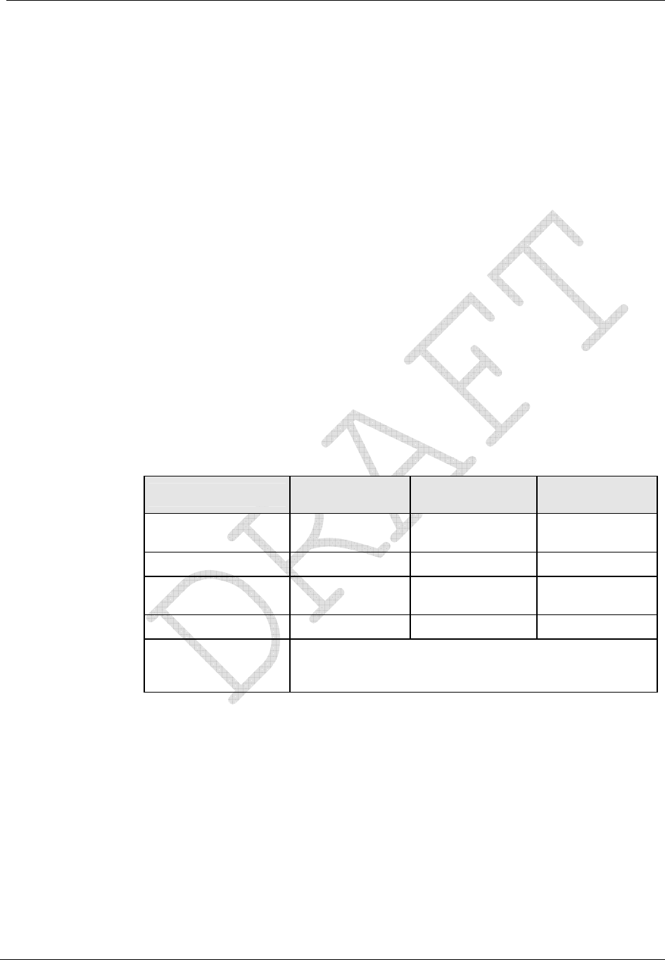
Operation: CP1SD/T/L Version
CENTRON® Polyphase Meter Technical Reference Guide 75
Phase Voltage Deviation Check
Once every five seconds, the phase A voltage is combined with a user-defined percentage
tolerance (x) to determine the upper and lower bounds of the acceptable range for the other
voltages. The range of values for the percent tolerance is 1 to 25.
For Diagnostic #2 to pass, the following equations must be satisfied:
ACAc
ABAB
VxVVxV
VxVVxV
•−≥•+≤
•−≥•+≤
%)1(lower and %)1(upper
%)1(lower and %)1(upper
If the above equations are not met for three consecutive checks, the diagnostic check will
trigger. Although the meter is using VA as a reference voltage, it does not need to be correct
for this check to be valid. The percentage difference is the determining factor.
Diagnostic #2 Error Example
This example is for a Form 9S meter wired for a 277 Volt, 4-Wire Wye system, but the site
has an incorrect voltage transformer ratio. The meter was also programmed with a
percentage tolerance of 10%.
The following is the information from the SiteScan snapshot when the Diagnostic #2 error is
triggered.
Phase A Display
(Left Element) Phase B Display
(Center Element) Phase C Display
(Right Element)
Voltage Phase
Angles PhA 0.0° V PhB 119.4° V PhC 240.9° V
Phase Voltage PhA 119.2 V PhB 275.4 V PhC 279.1 V
Current Phase
Angles PhA 9.0° A PhB 125.5° A PhC 246.0° A
Phase Current PhA 6.8 A PhB 10.2 A PhC 9.8 A
Diagnostic Counters d1 000 d2 001 d3 000
d4 000 d5A 000 d5B 000
d5C 000 d5T 000 d6 000
The second step to diagnose a Diagnostic #2 error is to compare the different phase voltage
readings. This can be done several ways by simply comparing the readings or plugging the
values into the equation. In this case, A phase is about 120 volts while both B and C phases
are about 277 volts. This could indicate an incorrect voltage transformer ratio or a shorted
voltage transformer winding for the A phase transformer. This could also indicate that A
phase is correct and both B and C phases are incorrect. Also note that diagnostic counter d2
has incremented to “001”.

Operation: CP1SD/T/L Version
76 CENTRON® Polyphase Meter Technical Reference Guide
By using the equations above and substituting in the voltages for the upper and lower limits,
one can also see why the diagnostic check has failed. For Diagnostic #2 to pass, the
following equations must be satisfied:
3.107279.1 and 131.11.279
2.119%)101(279.1 and 119.2%)101(1.279
3.107274.5 and 31.114.275
2.119%)101(275.4 and 119.2%)101(4.275
><
•−>•+<
><
•−>•+<
and
One can see in the above equations that 275.4 and 279.1 are not less than 131.1. Further
investigation can begin on the circuit to determine the cause of the problem.
SiteScan Diagnostic #3
The purpose of this diagnostic is to verify that each individual phase current maintains an
acceptable current level with respect to the others. This diagnostic check may indicate one
or more of the following problems:
Current diversion
Open or shorted current transformer circuit
Internal meter measurement malfunction
During the test, if one or more currents fall below the user defined “low current threshold”,
and at least one current is above this level, then a diagnostic error is triggered.
Inactive Phase Current Check
Diagnostic #3 checks every five seconds to verify that the meter is receiving a configured
current level for each individual phase. If the meter fails three consecutive checks, the
Diagnostic #3 check will trigger.
Once every five seconds, all phase currents are checked against a user-defined “low current
value” to verify that the current value is above this value. If one or more currents fall below
the low current value, and at least one current remains above this value for 3 consecutive
checks, the CENTRON Polyphase meter will trigger the error. The error will not be
triggered if all the currents fall below or above the user-defined value.
The starting current of:
transformer rated meters, CL 20, is 5 mA.
self-contained meters, CL 200, is 50 mA.
the CL320 version is 80 mA.
Therefore, a selected “low current value” of 100 mA would require at least one phase above
and below the starting current in order to activate the diagnostic.
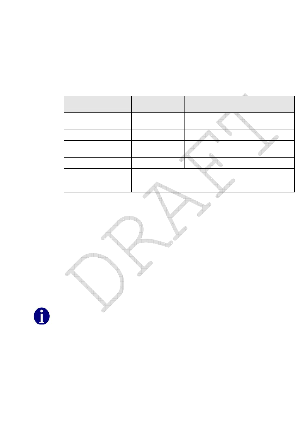
Operation: CP1SD/T/L Version
CENTRON® Polyphase Meter Technical Reference Guide 77
Refer to the PC-PRO+ Advanced documentation for instructions on how to program this
value into the CENTRON Polyphase meter.
Diagnostic #3 Error Example
This example is for a Form 9S meter wired for a 277 volt, 4-Wire Wye system, but the site
has a shorted current transformer. The “low current value” is set at 25 mA.
The following is the information from the SiteScan snapshot when the Diagnostic #3 error is
triggered.
Phase A Display
(Left Element) Phase B Display
(Center Element) Phase C Display
(Right Element)
Voltage Phase
Angles PhA 0.0° V PhB 119.4° V PhC 240.9° V
Phase Voltage PhA 276.2 V PhB 277.7 V PhC 277.0 V
Current Phase
Angles PhA 9.0° A PhB --------- PhC 246.0° A
Phase Current PhA 11.8 A PhB --------- PhC 5.2 A
Diagnostic Counters d1 000 d2 000 d3 001
d4 000 d5A 000 d5B 000
d5C 000 d5T 000 d6 000
The second step to diagnose a Diagnostic #3 error is to compare the different phase current
readings. In this case A and C phases both have current passing through the elements while
B phase (center element) has no current. The dashes indicate that current is zero or too low
to measure accurately. Accurate measurement is considered to be 0.5% of class rating for
the current:
CL 20 = 10 mA
CL 200 = 1 Amp
CL 320 = 1.6 Amps
This could indicate an open or shorted current transformer or current diversion. Also note
that diagnostic counter d3 has incremented to “001”.
It is possible to see dashes where the current information should be, but have no
Diagnostic #3 error present. See the SiteScan Toolbox Mode for more information.

Operation: CP1SD/T/L Version
78 CENTRON® Polyphase Meter Technical Reference Guide
SiteScan Diagnostic #4
The purpose of this diagnostic is to verify that the current elements are sensing and
receiving the correct current for each phase. It is basically a power factor check diagnostic.
This diagnostic check may indicate one or more of the following problems:
Poor load power factor conditions
Poor system conditions
Malfunctioning system equipment
Diagnostic #1 must be enabled and passed for this diagnostic to be enabled, so that the
system can assume all the phasors are in the relatively correct orientation. Each phase must
also exceed a configured minimum current threshold in order for it to be tested. Then the
user-defined angle tolerance is the parameter used to check the phasors.
Low End Threshold Current
The low end threshold current for Diagnostic #4 is adjustable based upon the class of the
meter from 0.5% of class to 5% of class.
Phase Angle Displacement Check
Diagnostic #1 must be enabled and must pass for Diagnostic #4 to be enabled and check for
a problem. This will allow the system to make the assumption that all the phasors are in the
relatively correct orientation and that there is no wiring problem. Since the voltage angles
passed Diagnostic #1, the meter will assign the voltage phasors to be constant at the typical
phasor angle.
If Diagnostic #1 passes, the meter will then determine the angle of each current phasor with
respect to VA for Diagnostic #4. The meter will monitor each current phasor angle for
validity with respect to the meter’s form number and service type. Diagnostic #4 will take
the “typical” phasor diagram at unity PF for a particular form number and service type and
place a user-defined envelope around each current phasor, where the actual phasor must be
found for the diagnostic check to pass.
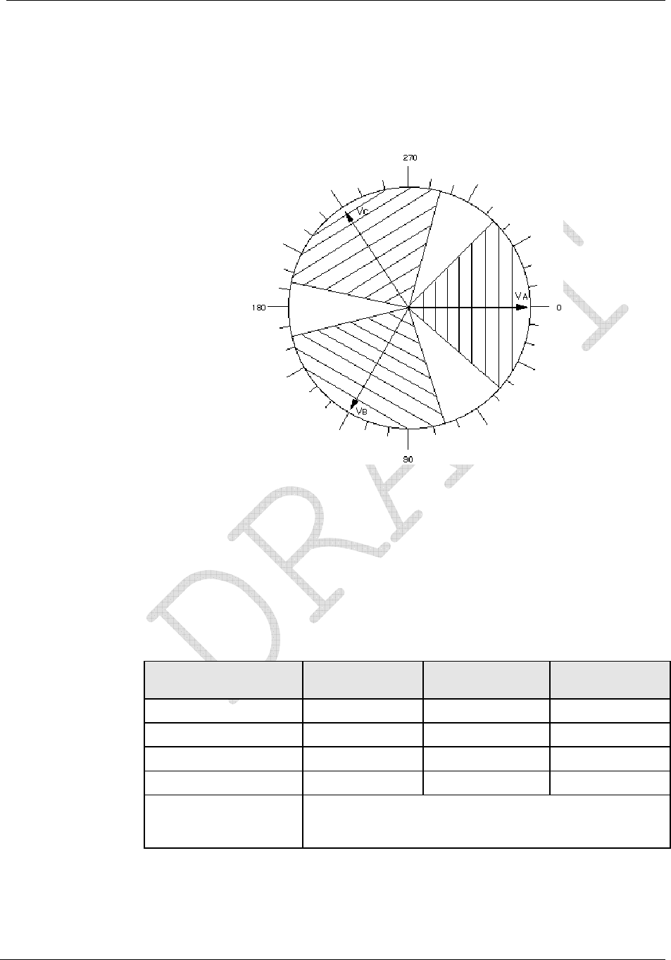
Operation: CP1SD/T/L Version
CENTRON® Polyphase Meter Technical Reference Guide 79
An example would be if a typical diagram has the C phase current angle at 240° and the user
has programmed an acceptable envelope of ±45° around that phasor, then the actual current
phasor must be between 195° to 285° from VA for the diagnostic to pass that check. The
system will check each current phasor in a similar fashion. Here, the current vector must be
within ±45° of the voltage vector for Diagnostic #4 to pass.
Figure 32: Envelope Example
Diagnostic #4 Error Example
This example is for a Form 9S meter wired for a 4-Wire Wye system with ABC phase
rotation, but the site has a poor load power factor condition. The meter was programmed
with a tolerance level of ±45° for Diagnostic #4 and Diagnostic #1 was also enabled and has
already passed.
The following is the information from the SiteScan snapshot when the Diagnostic #4 error is
triggered.
Phase A Display
(Left Element) Phase B Display
(Center Element) Phase C Display
(Right Element)
Voltage Phase Angles PhA 0.0° V PhB 120.4° V PhC 239.8° V
Phase Voltage PhA 120.8 V PhB 120.0 V PhC 119.3 V
Current Phase Angles PhA 2.0° A PhB 119.8° A PhC 297.2° A
Phase Current PhA 6.8 A PhB 10.2 A PhC 9.8 A
Diagnostic Counters d1 000 d2 000 d3 000
d4 001 d5A 000 d5B 000
d5C 000 d5T 000 d6 000
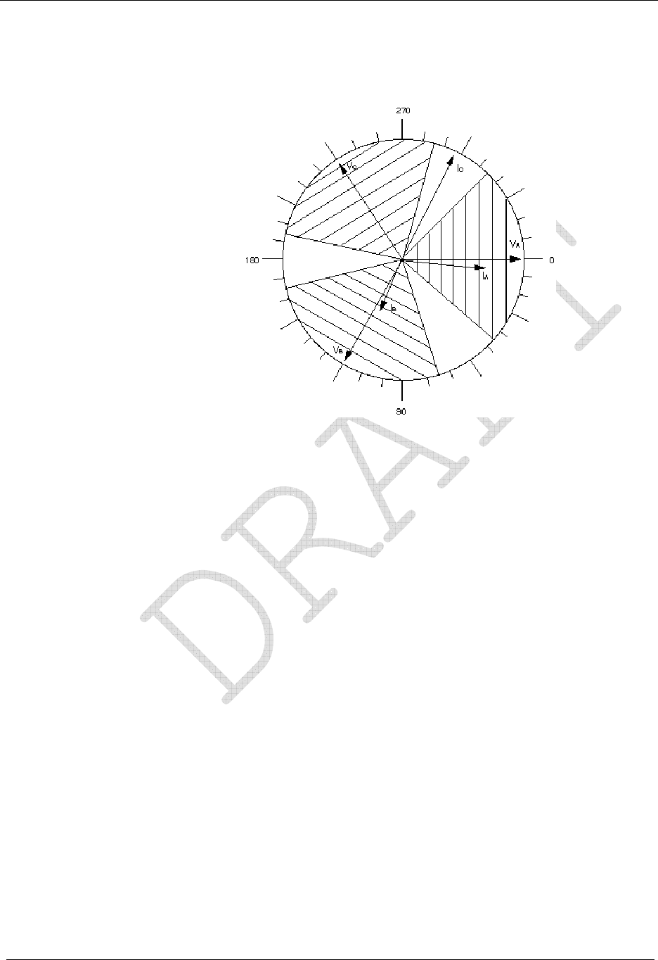
Operation: CP1SD/T/L Version
80 CENTRON® Polyphase Meter Technical Reference Guide
The next step is to graphically plot the above information into a phasor diagram as shown in
the figure below.
Figure 33: Phasor Diagram
By comparing the phasor diagram drawn from the information found in the snapshot versus
the typical phasor diagram, it becomes clear that the C phase current is out of the user-
defined envelope. The correct phasor should be around 240.0°, not the 297.0° where the
phasor currently is. This is not a problem with the meter or a wiring problem at the site, but
it does indicate a poor load power factor condition which may need to be corrected. Also
note that diagnostic counter d4 has incremented to “001”.
SiteScan Diagnostic #5
The purpose of this diagnostic is to check for the presence of DC on any of the current
phases. If DC is present on a phase, depending on the amount, this can adversely affect the
metering of power on that phase. The DC has the affect of distorting the waveform seen on
the secondary side of the CT.
A DC index is calculated for every current phase present for a given service. This index is
compared against a threshold that was established through extensive data analysis applying
different loads to the CTs and evaluating the DC Index. If a DC Index is found above the
threshold, then this is a single failure. As with the other diagnostics, there must be failures
on three consecutive checks before a failure is registered.

Operation: CP1SD/T/L Version
CENTRON® Polyphase Meter Technical Reference Guide 81
Current Waveform Distortion Check
Diagnostic #5 detects DC on a per-phase basis using what is know as a comb filter method.
Rectified loads produce even harmonics which are typically in phase with the voltage signal.
The algorithm works by summing current samples, which occur 90° after every zero
crossing of the voltage waveform. This information is accumulated for a sample interval.
These sample points should represent peak current values. If no DC is present on any of the
phases, the current waveforms will be symmetrical and the accumulation of the current
samples will be near zero. If DC is present on a phase, the current waveform is offset
vertically and the accumulation of the current samples will be significantly higher.
Diagnostic #5 will trigger when the level of DC present is such that the accuracy of the
CENTRON Polyphase meter could be affected. This level varies for different installations
based on the per-phase load conditions. When DC current is present, the CENTRON
Polyphase meter can be programmed to display the Diagnostic #5 error code (i.e. lock,
scroll, ignore). The number of times DC was present is available through meter
communications on a per-phase basis. The number of times that DC was present on all
phases is available by accessing the Toolbox Mode and viewing the Diagnostic #5 counter
or through meter communications.
SiteScan Diagnostic #6
The purpose of this diagnostic is to check for the presence of harmonic distortion.
Unlike the other diagnostics, Diagnostic #6 has a programmable minimum duration before
the condition is triggered. The minimum duration may be programmed from 5 to 3600
seconds in increments of 5 seconds.
The check is performed every 5 seconds. It compares the instantaneous %THD V for each
phase against a configured threshold and it compares the instantaneous %TDD I for each
phase against a configured threshold. The %THD V threshold and the %TDD I threshold
may both be configured from 1.0 to 35.0.
Once the condition occurs, the check must pass twice in a row for the condition to clear.
Diagnostic #6 Error Example
The following is the information from the SiteScan snapshot when the Diagnostic #6 error is
triggered.
Phase A Display
(Left Element) Phase B Display
(Center Element) Phase C Display
(Right Element)
Voltage Phase
Angles 0.00 119.20 239.20
Phase Voltage 120.875 120.000 120.150
Current Phase
Angles 359.10 118.40 237.50
Phase Current 5.8 6.0 5.9
%THD V 0.330 7.730 0.280

Operation: CP1SD/T/L Version
82 CENTRON® Polyphase Meter Technical Reference Guide
Phase A Display
(Left Element) Phase B Display
(Center Element) Phase C Display
(Right Element)
%TDD I 0.010 0.500 0.500
Diagnostic Counters d1 0 d2 0 d3 0
d4 0 d5A 0 d5B 0
d5C 0 d5T 0 d6 1
The snapshot data indicates that there was harmonic distortion on Vb. Also note that the
diagnostic counter d6 has incremented to 1.
Testing, Troubleshooting, and Maintenance
This section provides information and instructions to help you test and maintain the
CENTRON Polyphase meter. Topics covered include:
Visual indicators
Energy testing
Demand testing
Recommended testing procedures
TOU schedule testing
Field testing
Troubleshooting (fatal and non-fatal errors)
Maintenance
Visual Indicators
The Infrared Test LED, as well as several other annunciators, assist you in testing and
troubleshooting the CENTRON Polyphase meter.
Infrared Test LED
The meter is equipped with an Infrared (IR) Test Light Emitting Diode (LED) for testing
meter accuracy; the LED is located at the top of the meter. The pulse weight represented by
the LED is programmable through the PC-PRO+ Advanced programming software for a
CP1SDTL meter. The programming software allows a different pulse weight value for the
LED in the following display modes: Normal, Alternate, Test, and Test Alternate. The meter
can be programmed to drive the Test LED with a variety of energy values, depending upon
the energy quantities selected in the configuration.
Annunciators
The CENTRON Polyphase meter is equipped with a variety of annunciators for a more
meaningful display.

Operation: CP1SD/T/L Version
CENTRON® Polyphase Meter Technical Reference Guide 83
Load Indication/Direction Annunciator
The CENTRON Polyphase meter is equipped with a Liquid Crystal Display (LCD) load
emulation indicator. The Load Emulator follows the Infrared Test LED. For each pulse of
the Test LED, the Load Emulator increments one segment. The operation of the Load
Emulator depends on the quantity being pulsed.
If the quantity being pulsed is “Delivered-Only”, then the Load Emulator scrolls to the
right when energy is being delivered and lights the left arrow when energy is being
received.
If the quantity being pulsed is “Received-Only”, then the Load Emulator scrolls to the
left when energy is being received and lights the right arrow when energy is being
delivered.
If the quantity being pulsed is “Delivered and Received”, then the Load Emulator
scrolls to the right when energy is being delivered and scrolls to the left when energy is
being received.
When the meter is in Toolbox mode, the Load Emulator does not follow the Test LED.
Instead, the operation of the Load Emulator depends on the quantity that is currently being
displayed. If the quantity being displayed is a Phase quantity, then the Load Emulator scrolls
to the right if energy flow on that phase is currently delivered or scrolls to the left if energy
flow on that phase is currently received. If the quantity being displayed is a Diagnostic
Counter, then the Load Emulator is turned off.
Figure 34: Load Emulator Segment Progression
Phase-Voltage Indication Annunciators
The CENTRON Polyphase meter is equipped with three LCD voltage indicator
annunciators. They are located in the lower left portion of the LCD display. Illuminated
annunciators (VA, VB, and VC) indicate active voltage for these respective phases.
Depending on how the user configures the meter, a loss of voltage may be indicated with
either a missing or flashing annunciator.

Operation: CP1SD/T/L Version
84 CENTRON® Polyphase Meter Technical Reference Guide
Nominal Voltage Indication Annunciator
The CENTRON Polyphase meter is equipped with a nominal voltage indication
annunciator. This annunciator indicates the voltage value to which the nominal voltage is
nearest. Nominal voltage indication values are 120, 240, 277, and 480.
Test Mode Annunciator
The CENTRON Polyphase meter is equipped with a Test Mode LCD annunciator. Located
in the lower left portion of the display, this annunciator is present when Test Mode or Test
Alternate Mode is activated. The word “TEST” appears on the display during Test Mode
activation. The words “ALT” and “TEST” appear on the display during Test Alternate
Mode activation. The “TEST” annunciator will also flash when the meter is in Toolbox
Mode.
Energy Testing
The CENTRON Polyphase meter is a CL 0.2 accurate meter and requires no calibration
adjustments. Verification of accuracy of energy and demand may be verified in many ways.
Testing With the Infrared Test LED
Verification of metered energy values by the meter can be accomplished by using the
pulsing infrared LED located in the 3 o’clock position of the faceplate.
With a constant load applied, the IR LED pulses are compared to the output of a
conventional high accuracy watthour standard. This is accomplished using an IR-compatible
optical pickup device and a pulse counter.
Follow these steps to test the Wh with the LED:
1 Program the meter with the desired pulse quantity(s) and pulse weight(s) Ke.
2 Apply a constant delivered watts load (Wapp) to the meter.
3 Verify that the LED pulses properly either by counting the pulses or using a pulse
counter to compare pulses from the meter under test to the standard. To determine the
number of pulses per second, use the following equation:
Keseconds
hour
NW secondper pulses app 1
3600
1
#•••=
where N is the coil factor for single phase test method as shown in the table below.

Operation: CP1SD/T/L Version
CENTRON® Polyphase Meter Technical Reference Guide 85
If the meter is being tested using single phase test methods, a coil factor must be included in
the calculations. See the table below for the appropriate factor.
Meter Coil Factors
Form Series A Phase Only B Phase Only C Phase Only
9(8)1, 16(15,14) 3 1 1 1
1 When testing under true polyphase conditions, Forms 9 and 16 can only be tested as a 4-Wire
Wye. These forms cannot be tested as 4-wire deltas because of present limitation inherent in the
test equipment.
If accuracy or repeatability is poor, the Kh may be incorrect or the “settling time” in
the test bench must be adjusted. (Itron recommends a 4–5 second settling time.)
Testing Using the Load Indication Annunciator
The CENTRON Polyphase meter is capable of visually being tested by using the load
emulation annunciator shown in Load Indication/Direction Annunciator. As further
discussed in the load emulation annunciator section, the load emulation annunciator scrolls
at a rate proportional to the programmed energy constant.
Testing Using the Energy/Time Method
As an alternate to the above methods, the energy accumulated by the registers and a
reference standard can be read directly from the display and compared over a period of time.
Energy readings displayed while the meter is in the Test Mode are in floating decimal
format. This will result in maximum resolution for short duration tests.
Recommended Energy Testing Procedures
Testing solid-state meters on test boards designed primarily for electromechanical meters
may sometimes give unexpected results. Erroneous readings could occur on light-load (LL)
tests when the test sequence calls for a light-load test following a full-load (FL) or power-
factor (PF) test. In some cases, PF readings could also be in error when following a FL test.
The errors are always positive and may be a few percent for PF and even greater for LL.
The problem is aggravated on lower voltages and when using large test constants, Kt,
similar to the typical Kh values of comparable induction meters. This problem does not exist
on modern test boards with their latest software.
Test Description
A typical meter test sequence consists of:
1 The voltage and current ramp up at unity power factor to the FL level.
2 A pulse from the meter starts the FL test and another pulse ends it.
3 The phase angle then changes for the PF test. The current may stay at the FL level or
ramp down to zero and back up for the phase angle change.
4 A pulse from the meter starts the PF test and another pulse ends it.

Operation: CP1SD/T/L Version
86 CENTRON® Polyphase Meter Technical Reference Guide
5 The current ramps (directly or through zero) to the LL current level at unity power
factor.
6 A pulse from the meter starts the LL test and another pulse ends it.
Most test boards use jogging (slewing) immediately following a FL or PF test to shorten the
time required for the next test to start. The energy used for jogging may be more than
enough to cause the next pulse from the meter even before the ramping of current or
changing of phase angle is completed. If the trigger to start the next test is armed and ready
during the jogging or transition to the next test level, an unexpected pulse may cause the test
to start too soon. This obviously will result in erroneous readings. Some settling time is
necessary for the test board power, the reference standard, and the meter under test to
stabilize after the change to a new test level.
Most test boards provide a settling time (programmable or fixed) and will not recognize
another test pulse following the completion of a test until the jogging, ramping, and settling
time have all transpired. The CENTRON Polyphase meter needs a settling time of about
three to five seconds after the new test level has been reached before the test starts.
Recommendations
Erroneous test results caused by the problems previously described can probably be
corrected by implementing one of the following suggestions. Even if there are no bad
readings, Solution 3 can cut the total test time significantly without sacrificing test
verification certainty. The suggested solutions are:
1 Change the test sequence to avoid jogging before the light-load test.
2 Upgrade the test board to meet the requirements listed previously.
3 Program the meter and test board for a small test constant. This will avoid jogging and
also give the added benefit of shorter test time.
Solution 1
This is the preferred solution, since it results in shorter test times and can be implemented
simply by programming the meter for a smaller test constant and settling the test board
accordingly.
The CENTRON Polyphase and most other solid-state meters have the capability of being
programmed for a much smaller test constant (Kt), such as one-tenth or one-twelfth of the
energy required for one “disk revolution” of the meter. With the test pulses running 10 to 12
times faster, there is the possibility of shortening the test time considerably, but not by a
factor of 10 or 12. It still takes a finite amount of time to obtain meaningful results.
Solution 2
Change the test sequence so that the LL test is first, followed by the PF test and then the FL
test. This should prevent all jogging from occurring between tests and will probably
eliminate the erroneous readings. This is the quickest solution to implement since it requires
no changes to the test board or the meter.

Operation: CP1SD/T/L Version
CENTRON® Polyphase Meter Technical Reference Guide 87
Solution 3
Install the latest test board software revision. A test board ideally should recognize no new
test pulses after the completion of a test until jogging, ramping, and settling time have all
transpired. Settling time should be programmed for three to six seconds. There is nothing to
be gained by using settling times greater than six seconds.
Recommended Test Setup for Minimizing Test Time
The following settings are recommended for obtaining test uncertainties of less than 0.1%
and at minimum test times:
1 Program the test board settling time for five seconds.
2 Program the meter and test board for a small test constant, Kt, in some convenient
fractional value of the traditional Kh. For this example, 1/12 of the traditional Kh of the
equivalent electromechanical meter is used. (The use of decimal values may be
preferred for simplification of math.)
3 Use 12 pulses (1 rev) for FL.
4 Use 12 pulses for PF.
5 Use 1 pulse for LL.
6 For element tests, the FL and PF pulses can be divided by the number of elements,
always rounding up for fractional values.
The total test time for a series FL, PF, LL sequence can be shortened by more than one
minute compared to the time required for an electromechanical meter or a solid-state meter
using the equivalent test constants. If LL element tests are used, the time savings will be
much greater.
Recommendations for Minimum Variability
The variability of testing a CENTRON Polyphase meter can be reduced by lengthening the
test times (using more pulses). Doubling or tripling the recommended minimum test time
will reduce the variability by a factor of two or three. Very little improvement is realized by
running longer than about 45 seconds for each test.
Demand Testing
Testing consists of comparing the readings displayed on the CENTRON Polyphase meter to
the actual demand as determined using a high-accuracy RMS responding reference standard.
The standard should have pulse outputs proportional to Wh/pulse (or VAh/pulse).
Pulses from the reference standard are accumulated over one demand interval, and then the
total pulse count representing watt-hours or volt-ampere-hours is converted to an average
demand value using the formulas in Demand Calculations.
Because of the high accuracy of the CENTRON Polyphase meter, the following is the
recommended procedure for testing these meters.
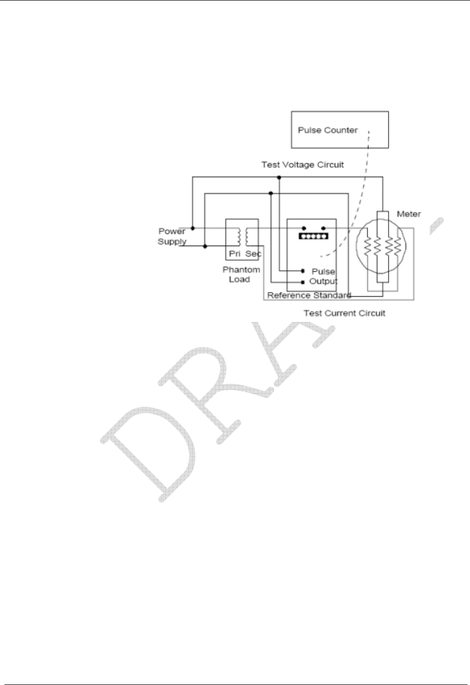
Operation: CP1SD/T/L Version
88 CENTRON® Polyphase Meter Technical Reference Guide
Demand Test Method
1 Connect the meter under test and the reference standard in the same circuit with all
voltage coils in parallel and current coils in series as per standard meter testing
procedures.
Figure 35: Test Connections
2 Apply rated voltage to the meter under test and the reference standard. Set the test
current to the desired level (FL, LL, or PF test amps or any desired level within the
meter rating). To ensure that the supply polarities are correct, check that the Load
Emulation Annunciator is traversing in the forward direction. Switch off only the
current to both the meter and the standard.
3 Reset and enable the pulse counting device.
4 Put the CENTRON Polyphase meter into Test Mode by pressing the Test switch. Once
this has been done, push in the Demand Reset switch to zero the test registers and start a
new demand interval.
5 Start the test by switching on the current to all meters and the reference simultaneously.
6 The End-of-Interval (EOI) flag will appear for five seconds in the display after the end
of the demand interval. At this time, switch off the current to all meters simultaneously
and stop the pulse count. Do not disconnect the voltage to the meter.
7 Record the pulse counter total and the values displayed on the CENTRON Polyphase
meter.
8 Perform calculations A, B, C, and D (if applicable) in the demand calculations section
and compare the results.

Operation: CP1SD/T/L Version
CENTRON® Polyphase Meter Technical Reference Guide 89
Meter Single Phase Test Constants (SPTC)
Form Series A Phase
Only B Phase
Only C Phase
Only
9 or 16 3Ø, 3W, 0.911 .866 .0866 1
9, 16, or 14 3Ø, 4W, wye 1 1 1 1
This test method is valid for kWh, kVAh, kvarh, kW, kVA, and kvar at any load or
power factor.
Demand Calculations
With solid-state metering, conducting energy and demand tests may be considered
redundant since they are both results of the same measurement.
Calculation A: Actual Active Energy (kWh)
Actual active energy is calculated using the following formula:
kWh = PT x Kh x N/1000
where: Kh = watt-hours per pulse output value from the reference
standard. (A watt and/or a VA standard must be used.)
PT = Total pulses accumulated from the reference standard
N = Coil factor (See Testing With the infrared Test LED)
Pre-calculate the total pulses expected with the following formula to ensure that the pulse
counter display does not overflow:
PT x Kh = V x I x T/(Kh x 60)
where: V = Voltage applied to standard
I = Current applied to standard
T = Test Mode demand interval length in minutes
If Test Mode display is in watt-hours (Wh), divide by 1000 to get kWh.
Calculation B: Actual Active Demand (kW)
Actual active demand is calculated using the following formula:
kW = kWh x 60/T
where: T = Test Mode demand interval length in minutes
Calculation C: Actual KVA Hours
kVAh = PT x Kh x N/ (1000*SPTC)

Operation: CP1SD/T/L Version
90 CENTRON® Polyphase Meter Technical Reference Guide
where: N = Coil factor (See Testing With the Infrared Test
LED)
SPTC=Single phase test constant (See the table in
Demand Test Method)
Calculation D: Actual kVA Demand
kVA = kVAh x 60/T
where: T = Test Mode demand interval length in minutes
Field Testing
Field testing of the CENTRON Polyphase meter may be accomplished with conventional
methods using either the infrared test pulses or the load emulation annunciator.
Required Hardware
The typical field test setup consists of a phantom load, a portable standard, and an infrared
test pulse adapter with counter or snap switch assembly.
Test Method Using Infrared Pulse Adapter
The pulse adapter runs the test for a programmed number of pulses. The number of pulses is
set on the test pulse adapter by the use of counter switches. The adapter will automatically
start the test when the START COUNT button is pressed.
When the test begins, the test pulse adapter counts the pulses it receives from the meter until
the programmed number of pulses have been received.
When this occurs, the pulse adapter automatically shuts off the portable standard. The
standard then displays the number of equivalent disk revolutions which is then compared to
the number of pulses for the test.
Test Method Using a Snap Switch Assembly
This method is similar to the above except starting and stopping of the standard is
performed manually.
To conduct the test, the technician observes the position of the load emulation annunciator
and simultaneously starts the standard through the snap switch. After observing a
predetermined number of emulated disk rotations, the technician stops the standard with the
snap switch. A comparison is then made between the predetermined number of emulated
disk rotations and equivalent disk rotations indicated on the watthour standard.
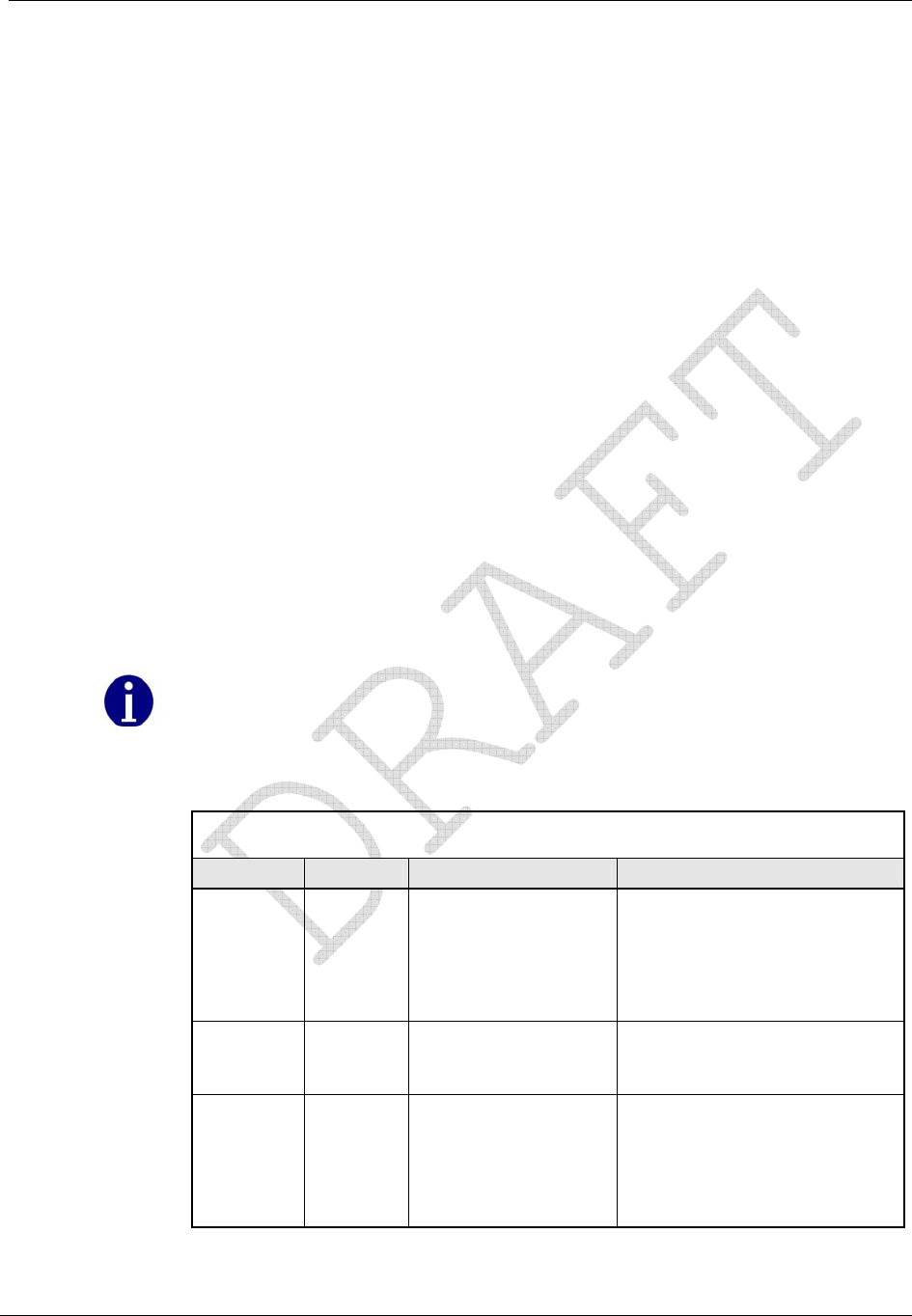
Operation: CP1SD/T/L Version
CENTRON® Polyphase Meter Technical Reference Guide 91
Troubleshooting
Typically, meters are placed in a very unfriendly environment. While the CENTRON
Polyphase meter is designed to perform within this harsh environment, things can go wrong
with the meter or installation.
Fatal Errors
Fatal errors cause the display to lock on the error code because of the possibility that billing
data may have been corrupted or that the meter may not be operating correctly. If multiple
fatal errors occur, the one with the lowest number will be the error code that locks on the
display.
The CENTRON Polyphase meter will check for fatal errors:
when a meter reconfigure is performed.
when power is initially energized and upon future power restoration.
while performing key operations.
The different fatal errors should be handled as described in the table below. Fatal errors can
only be cleared by performing a Factory Reset on the meter will wipe out all information in
the meter, so be sure to try to retrieve any meaningful data from the meter prior to
performing the Factory Reset. After this is performed, the meter must be reprogrammed.
Sometimes when a battery is plugged into a meter while the meter is powered
down, it will result in a fatal error when the meter is powered up. This is due to
an unstable voltage on the battery. In this case, the fatal error can be ignored and
a Factory Reset performed on the meter. To prevent these fatal errors from
occurring, always power up the meter before plugging a battery into it.
Fatal Errors
Error Code Error Possible Cause Error Description
FAtError1 MCU
FLASH
Error
The meter has
detected a problem
with the program
memory.
If this error occurs, Factory
Reset the meter, reprogram the
meter and check for proper
operation. If the error continues
to exist, return the meter for
repair.
FAtError2 RAM
Error The meter has
detected a problem
with the RAM.
If the meter detects this
problem, return the meter for
repair.
FAtError3 DATA
FLASH
Error
The meter has
detected a problem
with the data flash
(non-volatile
memory).
If this error occurs, Factory
Reset the meter, reprogram the
meter and check for proper
operation. If the error continues
to exist, return the meter for
repair.

Operation: CP1SD/T/L Version
92 CENTRON® Polyphase Meter Technical Reference Guide
Fatal Errors
Error Code Error Possible Cause Error Description
FAtError4 Front
End
Process
or Error
A problem has
occurred with the
metrology portion of
the meter.
If the meter detects this
problem, return the meter for
repair.
FAtError5 Power
Down
Error
A problem has
occurred while saving
billing data at time of
a power outage.
The billing data has been
corrupted. Factory Reset the
meter, reprogram the meter and
check for proper operation,
including several power cycles.
If the error continues to exist,
return the meter for repair.
FAtError6 File
System
Error
The meter has
detected a problem
with the file system
If the meter detects this
problem, return the meter for
repair.
FAtError7 Operati
ng
System
Error
The meter has
detected a problem
with the operating
system
If the meter detects this
problem, return the meter for
repair.
Non-Fatal Errors
Non-fatal errors can be programmed to scroll during the one second display off-time or lock
on the meter display. If multiple non-fatal errors occur, the meter will display a combined
error message. For example, if a Low Battery error and a Loss of Phase error exist, the error
display will read Err 12----. In this case, if one of the errors had been programmed to
lock, and the other error had been programmed to scroll, the display will lock on the
combined error message.
Selecting a display mode by holding the magnet near the cover’s magnet icon at the seven
o’clock position allows that display mode sequence to scroll one time during a locked non-
fatal error. At the end of the display sequence, the error message locks onto the display
again.
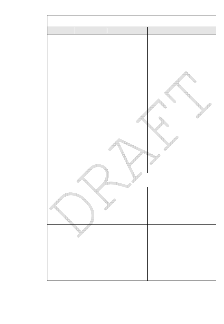
Operation: CP1SD/T/L Version
CENTRON® Polyphase Meter Technical Reference Guide 93
Non-Fatal Errors
Error Code Error Possible Cause(s) Error Description
Err 1----- Low
Battery
Error
Battery Voltage
Low
Battery Not
Connected
Properly
A low battery check is
performed once a day and
upon a set clock procedure. If
a low battery is detected, the
condition will remain until the
battery is replaced. As long as
the meter is not powered down
with a dead or missing battery,
the meter will continue to
function as normal. When the
battery is replaced while the
meter is powered up, the
meter will automatically detect
the new battery and clear the
error condition.
If the meter is powered down
with a dead or missing battery,
then, when power is restored,
the meter's clock will be off by
the duration of the outage, and
Load Profile and TOU will be
halted. When the battery is
replaced, a set clock
procedure is needed to clear
low battery error condition.
This will also restart TOU and
clear and restart Load Profile.
To retain data for TOU and Load Profile, the battery must be replaced
with the power applied to the meter.
Err -2---- Loss of
Phase
Error
The voltage on
one of the
phases dropped
below 45 volts.
The voltage on each phase is
checked every five seconds. A
phase must fail twice in a row
to cause an error.A Demand
Reset or a Clear STD or MFG
Status Flags after the voltage
returns will clear this error.
Err --3--- Time-of-
Use (TOU)
Error
• Current Season
is not
programmed.
• Current Year is
not
programmed.
• TOU halted due
to power down
with dead or
missing battery.
This is tested at power-up, at
midnight crossings, at season
changes, upon reconfigures
and upon set clocks.
Depending on the cause of the
error, it can be cleared with a
corrective reconfigure or with a
set clock with a good battery
present.
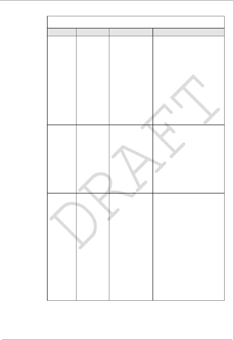
Operation: CP1SD/T/L Version
94 CENTRON® Polyphase Meter Technical Reference Guide
Non-Fatal Errors
Error Code Error Possible Cause(s) Error Description
Err ---4-- Reverse
Power
Flow Error
The configured
reverse power
threshold has
been reached
Reverse power is tested every
second and an accumulator
for it is maintained. If power is
delivered during the second,
then the accumulator is
cleared. If power is received
during the second, then the
accumulator is incremented. If
the accumulator reaches the
configured reverse power
threshold, then the error is
triggered.
A Demand Reset or a Clear
STD or MFG Status Flags with
power being delivered will
clear this error.
Err ----5- Clock/Load
Profile
Error
Load Profile
halted due to
power down with
dead or missing
battery.
This is tested upon power-up.
A set clock with a good battery
present will clear this error. Be
sure to read the Load Profile
data prior to setting the clock
to clear the error. The dead
battery will cause some invalid
intervals at the end of the
data. When the error is
cleared, Load Profile will be
restarted from the beginning to
purge the bad data.
Err -----6 Full Scale
Overflow
Error
The calculated
W delivered
demand at an
EOI exceeded
the configured
full scale value.
This is tested at a demand
EOI.The maximum demand
register continues to
accumulate and W delivered is
still correctly displayed. When
a demand reset is performed,
the correct maximum W
delivered will be added to the
cumulative register.
A Demand Reset or a Clear
STD or MFG Status Flags will
clear this error.
If a full scale overflow occurs,
check the installation to
ensure that the current
capacity of the meter has not
been exceeded. A full scale
overflow error in no way
affects the existing billing data.

Operation: CP1SD/T/L Version
CENTRON® Polyphase Meter Technical Reference Guide 95
Non-Fatal Errors
Error Code Error Possible Cause(s) Error Description
Err - 9--- SiteScan
Error SiteScan auto
service
detection could
not determine
the meter's
service type.
This is tested after the power-
up delay time has expired
following a power-up, an exit
Test mode and a reconfigure
of SiteScan configuration data.
While this condition is present,
SiteScan Diagnostics and
Voltage Quality are disabled.
Once a SiteScan error occurs,
SiteScan will continue to test
for it every 5 seconds until the
service is determined. When
the service is determined, the
error condition is cleared.
Other Problems
Demand Reset Cannot Be Initiated Through PC or Handheld
Insufficient security.
Communication cannot be established. See Programmer Cannot Communicate with
Meter.
Incorrect or No Accumulation of kWh or kW
Demand Delay Selected—kW will not accumulate immediately after a power outage if
Cold Load Pickup (demand delay) has been selected. Accumulation will begin
immediately after demand delay has expired. Verify meter program and reconfigure
meter.
Component Failure—Return the meter for repair.
Meter is not being tested properly—See Recommended Testing Procedures.
Reset Mechanism Does Not Initiate Demand Reset
Reset Has Occurred Within Last Programmable Time Period, e.g., 60 Seconds—
Manual demand reset cannot occur within 60 seconds of the previous demand reset.
Wait 60 seconds before trying again.
Reset Switch Disabled—Reset switch may be disabled through software.
Register Board not Properly Installed in Upper Housing—Verify that the Register
board is fully engaged with the upper inner cover.
Blank Display
Power Not Applied to Meter—Apply voltage to A phase (or phase-to-phase voltage
with a polyphase power supply).
Voltage Too Low for Meter Startup—the CENTRON Polyphase meter requires at least
45 volts to start up.
Voltage Connector Loose—Voltage connector of the meter loose from the Register
board; re-secure the connector.
Component Failure—Return the meter for repair.
Board-to-Board Connector Not Seated—Verify proper connection of board-to-board
connector.

Operation: CP1SD/T/L Version
96 CENTRON® Polyphase Meter Technical Reference Guide
Time and Date Wrong (TOU Version)
Time/Date Wrong in PC or Handheld Device—Verify and update time/date in
programming device and download new time and date to meter. Refer to the appropriate
software manual for more detailed directions.
Wrong Line Frequency—Verify proper line frequency is selected in setup routine in
programming software. Select proper frequency and reconfigure meter.
Battery Failure During Power Outage—Verify battery voltage. Replace battery and
download new time and date.
Daylight Savings Time Not Programmed Correctly—Verify DST is selected in
program. Reconfigure meter with correct program.
Component Failure—Return meter for repair.
Optional Output Contact Closures Not Occurring
Meter Improperly Programmed—Verify all required programmable values were
defined.
Output Wiring Not Properly Connected—Verify wiring and correct.
Meter Not Supplied with Output Electronics—Retrofit proper output circuitry.
Option Board Component Failure—Replace Option Board.
Meter Component Failure—Return meter for repair.
Low (or No) Wetting Voltage—Apply wetting voltage.
No Load—Confirm load should be present.
Programmer Cannot Communicate with Meter
Optical Probe Cable Assembly Failure—Check cable with known meter that
communicates. Check meter against known cable that is functioning. Also check
batteries in cable assembly (if applicable).
COM Port in Programmer Is Set Wrong—Verify proper COM port number has been
selected in the setup routine of the programming software. If the wrong COM port is
selected communications will not occur.
Security Code in Meter—If security codes have been downloaded to the meter, the
programming device must have the proper code to make connection to the meter. Verify
security codes in the setup routine of the programming software.
Cable Not Connected Properly—Verify optical probe lines up properly over the optical
connector. Re-install cover for proper alignment. Verify PC (or handheld) and cable are
securely connected and attached to the correct COM port.
Incorrect Cable Selection—Wrong cable selected in Options | Optical Probes section of
PC-PRO+ Advanced.
Main Register Electronics Failure—Return meter for repair.
Magnetic Switch Does Not Activate the Alternate or Toolbox Mode
Magnetic Field Is Too Weak—Place magnet closer to switch or use stronger magnet.
Magnet was not in place for four consecutive seconds.
Magnetic Switch Failure—Return meter for repair.
Test Mode Switch Does Not Place Meter in Test Mode
No display items in Test Mode Display List.
Switch deactivated by software—Activate switch in software and reprogram meter.

Operation: CP1SD/T/L Version
CENTRON® Polyphase Meter Technical Reference Guide 97
Register Board not Properly Installed in Upper Housing—Verify that the Register
board is fully engaged with the inner cover.
Switch or Electronic Failure—Return meter for repair.
Diagnostic 1 Condition Incorrectly Active
Verify that meter determined the correct service type.
Diagnostic 2, 3, or 4 Condition Incorrectly Active
Verify that thresholds are not set too tight.
Counters Are Too High
Verify that thresholds are not set too tight.
Maintenance
Preventive Maintenance
No scheduled or preventive maintenance (other than battery replacement for TOU/Load
Profile versions) is necessary for the CENTRON Polyphase meter.
Line potential may exist on the battery terminals. Follow these
precautions:
• Never short-circuit batteries (such as by measuring current
capability with an ammeter).
• Do not recharge batteries.
• Do not store or transport batteries in metal or other
electrically conductive containers.
• Keep batteries separated. If stored in a container where
they can contact each other, face them in the same
direction to prevent short circuits.
• Do not operate batteries at temperatures above 85°C
(185°F).
• Dispose of batteries where they will not be punctured,
crushed, or incinerated.
• Discard the battery using proper hazardous waste
procedures.
Corrective Maintenance
Because of the high level of integrated packaging and surface-mount components, on-board
component repairs are not recommended. The entire meter should be returned to Itron, Inc.
Customer Service for repair.

CENTRON® Polyphase Meter Technical Reference Guide 99
Glossary of Terms
A floating decimal
A display format that allows a maximum number of
digits to the right of the decimal, but can display any
number of digits to the right of the decimal equal to
or less than that number specified
annunciator
A Liquid Crystal Display (LCD) label that is
displayed to identify a particular quantity being
displayed
L
B LCD
baud Liquid Crystal Display
Unit of data transmission signalling speed, roughly
analogous to bits per second (bps)
LED
D Light-Emitting Diode
M
display duration
The programmed number of seconds that a quantity is
displayed on the LCD before it is replaced with the
next quantity in the display sequence
magnetic reed switch
A mechanical switch consisting of a thin metal
contact which is closed by an external magnetic field
E
N
EEPROM nonvolatile memory
Electrically Erasable Programmable Read Only
Memory. A memory chip that can only be erased by
an electrical signal (retains data during a power
outage)
See EEPROM
R
RS-232
electronic detent A communication media whereby information is
transmitted through a serial bit stream
An algorithm in firmware which restricts the device
to metering energy flow only to the customer
(unidirectional metering)
EPROM
Erasable Programmable Read Only Memory. Similar
to EEPROM except it requires ultraviolet light to be
erased
F
firmware
Computer programs stored in non-volatile memory
chips (ROMs, PROMs, EPROMs, EEPROMs, etc.)
fixed decimal
A display format that always retains the same number
of digits to the right of the decimal point

CENTRON® Polyphase Meter Technical Reference Guide 101
Index
About This Manual • 1
Alternate Display Mode • 45
annunciator • 99
Annunciators • 83
antenna
RF • 25
Application of Power and Power-up • 37
base • 2
base metrology • 13
Battery Carryover • 52
baud • 99
Bit Resolution • 53
Blank Display • 96
board-to-board connector • 8, 17
button
test mode • 8
Calculation A
Actual Active Energy (kWh) • 90
Calculation B
Actual Active Demand (kW) • 90
Calculation C
Actual KVA Hours • 90
Calculation D
Actual kVA Demand • 91
Calendar Schedule • 50
Capacity • 53
Changing Display Modes • 44
Channel Configuration • 54
Characteristic Data • 5
circuit board • 8
metrology • 2, 28
Clearing Security Codes • 59
clock register • 17
Cold Load Pickup • 38
connector
board-to-board • 8, 17
Controls and Indicators • 31
Corrective Maintenance • 98
counter
power removal • 28
Counters Are Too High • 98
cover • 7
inner • 8
See also inner cover and outer cover • 8
Cross-Phase, Polarity, and Energy Flow Check •
73
Crystal Time synchronization • 7
Current Angle Tolerance • 73
Current Season Registers • 51
Current Waveform Distortion Check • 82
current/potential terminals • 8
cyclometer • 17
D
Daily Patterns • 51
Data Storage • 55
Day Types • 51
Demand Calculations • 90
Demand Data Display Items • 41
Demand Meter • 38
Demand Registers • 48
demand reset • 8
Demand Reset Button • 32
Demand Reset Cannot Be Initiated Through PC
or Handheld • 96
Demand Test Method • 89
Demand Testing • 88
detent register • 18
Detented Register • 20
Diagnostic #1 Error Example • 74
Diagnostic #2 Error Example • 76
Diagnostic #3 Error Example • 78
Diagnostic #4 Error Example • 80
Diagnostic #6 Error Example • 82
Diagnostic 1 Condition Incorrectly Active • 98
Diagnostic 2, 3, or 4 Condition Incorrectly
Active • 98
Diagnostic Displays • 47
Digits and Multipliers • 21
Dimensions • 6
Display • 25
display duration • 99
Display Functions • 4
Display Modes • 40

Index
102 CENTRON® Polyphase Meter Technical Reference Guide
Display Timing • 21
EEPROM • 99
Electrical • 4
electronic detent • 99
Electronic Detent • 26
electronic load indicator • 25
energy consumption • 25
Energy Data Display Items • 41
Energy Registers • 47
Energy Testing • 85
EPROM • 99
ESD damage • 8
Event Log • 56
Factory Programming Options • 21
Factory Reset • 37
Fatal Errors • 92
FCC Regulations • 27
Field Testing • 91
firmware • 99
Firmware Upgrades • 60
fixed decimal • 99
floating decimal • 99
forward energy flow • 18, 26
General Description • 2
General Information • 1
grounding measures • 8
Hall Effect
technology • 2
I/O module • 4
Implementing Security Codes • 59
Inactive Phase Current Check • 77
Incorrect or No Accumulation of kWh or kW •
96
Information Registers • 49
Informational Data Display Items • 42
Infrared Test LED • 32, 83
inner cover • 8
removing • 8
input/output-ready • 4
Inspection • 7
Installation • 7
Installing D/T/L Register Firmware on the PC •
60
Installing the Meter into Service • 8
Instantaneous Data Display Items • 42
Instantaneous Registers • 49
Interrogation • 49
Interrogation and Programming • 49
Interval Data Message (IDM) • 24
Interval Lengths • 54
Interval Make-up • 39
inversion counter • 28
inversion tamper (ITPR) • 28
IR light pipe • 8
ITPR • 28
K
Kilowatt Hours • 18
L
Last Season Registers • 51
LCD • 99
LCD display • 8
LCD Display Function • 19
LCD holder • 8
LCD housing • 25
LCD module • 17, 18
LCD register • 17
LED • 99
line frequency • 7
Liquid Crystal Display (LCD) • 32
lithium battery
shelf life • 7
Load Emulator • 34
Load Indication/Direction Annunciator • 84
Load Profile • 53
Load Profile Specifications • 53
Low End Threshold Current • 79
M
magnetic reed switch • 99
magnetic switch • 99
Magnetic Switch • 36, 44
Magnetic Switch Does Not Activate the
Alternate or Toolbox Mode • 97
Maintenance • 98
metal oxide varistor • 2
meter
resetting • 18
meter base • 2, 3, 7, 8, 23

Index
CENTRON® Polyphase Meter Technical Reference Guide 103
Meter Base • 2
meter cover • 7
meter inversion • 28
meter removal • 28
meter storage • 7
Metrology • 13
metrology base • 2
metrology board • 8, 28
metrology circuit board • 2
Mode Timeout • 44
module
LCD • 18
R300 • 23
register • 8
module holder • 3
MOV • 2
Net Metering • 27
Net Register • 20
Nominal Voltage Indication Annunciator • 84
Non-Detented Register • 19
Non-Fatal Errors • 93
nonvolatile memory • 99
non-volatile memory • 23
Normal Display Mode • 44
Normal Mode • 39
Operating Environment • 5
Operating Modes • 39
operating temperature range • 7, 25
Operation
Base Metrology • 13
CP1S Version • 17
CP1SD/T/L Version • 31
CP1SR Version • 23
optical connector • 7, 8
Optical Port • 36
Optional Output Contact Closures Not Occurring
• 97
Other Problems • 96
outer cover
removing • 8
Outputs • 4
PC-PRO+ Advanced Programming Software • 1
personality module • 2, 3, 4, 8
C1S • 17
C1SR • 23, 25
handling • 7
Personality Modules • 3
Phase Angle Displacement Check • 79
Phase Voltage Deviation Check • 76
Phase-Voltage Indication Annunciators • 84
Physical Description • 2, 17, 25
Power Circle Quadrants • 36
Power Down Procedures • 38
Power Flow • 33
Power Outage • 54
power removal counter • 28
Preventive Maintenance • 98
Product Availability • 4
Programmer Cannot Communicate with Meter •
97
Programming • 50
Proprietary Rights Notice • ii
PRO-READ • 1
Pulse Constants • 54
R
R300 module • 23
R300 Series • 60
random silent time • 27
Rate Annunciators and Active Rate Indicators •
52
Rates • 50
ReadOne Pro handheld reader • 28
Recommendations • 87
Recommendations for Minimum Variability • 88
Recommended Energy Testing Procedures • 86
Recommended Test Setup for Minimizing Test
Time • 88
Recording Duration • 56
register module • 8
Registers • 18, 25, 47
removal tamper (RTPR) • 28
removal tamper counter • 28
Required Hardware • 91
reset mechanism • 7
Reset Mechanism Does Not Initiate Demand
Reset • 96
resetting meter • 18
Resetting Values • 18, 27
Retrofit Kit
C1SR • 29
retrofitting • 8
Retrofitting the CP1SR Personality Module • 29

Index
104 CENTRON® Polyphase Meter Technical Reference Guide
Retrofitting with Personality Modules • 8, 30
reverse current flow • 28
reverse energy flow • 18, 26
reverse power flow • 28
RF antenna • 25
RS-232 • 99
RTPR • 28
Sampling • 14
SCM Testing • 28
Scroll Lock • 44
Season Change • 52
Seasonal Schedules • 51
Security Codes • 58
Segment Check • 21
segment test • 8
Selecting a Site • 7
Self Read and Snapshot Registers • 49
silent time • 27
SiteScan Diagnostic #1 • 73
SiteScan Diagnostic #2 • 75
SiteScan Diagnostic #3 • 77
SiteScan Diagnostic #4 • 79
SiteScan Diagnostic #5 • 81
SiteScan Diagnostic #6 • 82
SiteScan Meter Self-Diagnostic Checks • 62
SiteScan On-Site Monitoring System • 61
SiteScan System and Installation Diagnostic
Checks • 65
SiteScan Toolbox Mode • 62
Solution 1 • 87
Solution 2 • 87
Solution 3 • 88
Specifications • 4
Standard Consumption Message (SCM) • 24
storage
meter • 7
Storage • 7
Surge Protection • 14
tamper counter • 27
Tamper Detection • 28
tamper indication • 28
Technical Data • 5
Test Alternate Display Mode • 47
Test Description • 86
Test Display Mode • 46
Test Method Using a Snap Switch Assembly •
91
Test Method Using Infrared Pulse Adapter • 91
Test Mode • 39
test mode annunciator • 8
Test Mode Annunciator • 85
test mode button • 8
Test Mode Button • 37
Test Mode Lockout • 40
Test Mode Switch Does Not Place Meter in Test
Mode • 97
Test Mode Timeout • 40
Testing the CENTRON CP1SR Tamper Counter
• 28
Testing Using the Energy/Time Method • 86
Testing Using the Load Indication Annunciator •
86
Testing With the Infrared Test LED • 85
Testing, Troubleshooting and Maintenance • 22,
30
Testing, Troubleshooting, and Maintenance • 83
Time and Date Wrong (TOU Version) • 97
Time-of-Use (TOU) • 50
Toolbox Display Mode • 45
TOU Operation • 51
TOU Registers • 51
TOU Schedules • 50
TOU/Load Profile Meters • 38
TR • 25
transformer rated meter • 25
transformer ratio (TR) • 25
transmission cycle • 27
Transmission Scheme • 27
Troubleshooting • 92
U
Unpacking • 7
V
Visual Indicators • 83
Voltage and Current Measurement • 15
W
watt disk emulator • 25
Z
ZRO-C2 • 18
ZRO-C2 Resetter • 17, 25, 27