JBL Modemulator User Guide 3520 Ug
3520-modemulator-ug USR :: USR3520 Modemulator™ & M2M 3G Cellular Gateway
3520-modemulator-ug USR :: USR3516-EMU Modemulator™ Expansion Card
Modemulator User Guide 3520-modemulator-ug USR :: Product
User Manual: JBL Modemulator User Guide USR :: Product
Open the PDF directly: View PDF ![]() .
.
Page Count: 120 [warning: Documents this large are best viewed by clicking the View PDF Link!]
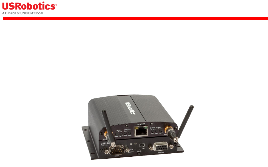
USRobotics® Courier® Modemulator™
User Guide & Technical Documentation
For the following products:
Modemulator & 3G M2M Cellular Gateway
USR3520, USR803520
Modemulator Upgrade Kit
USR3516-EMU
R24.0800.02
Rev 1.1 7/1/2016
For firmware version 1.0.03
Modemulator User Guide
Page 2 of 120
Contents
Contents .................................................................................................................................... 2
About This Guide ......................................................................................................................... 7
Symbols Used In This User Guide ............................................................................................... 7
Important Safety Instructions .................................................................................................... 8
General Recommendations For Use ......................................................................................... 8
Ambient Temperatures .......................................................................................................... 8
Explosive Atmosphere ........................................................................................................... 8
Driving ................................................................................................................................ 9
Medical Equipment ................................................................................................................ 9
ESD Notice ........................................................................................................................... 9
Class A Device ...................................................................................................................... 9
Chapter 1: Features ................................................................................................................... 10
Introduction .......................................................................................................................... 10
Overview of Main Features ................................................................................................... 10
Physical Features ................................................................................................................ 12
Mounting Instructions .......................................................................................................... 14
Chapter 2: Getting Started ......................................................................................................... 15
Verifying Modemulator Operation ............................................................................................. 15
Testing Modemulator Connectivity ............................................................................................ 18
System requirements .......................................................................................................... 18
Set Up Cellular Connectivity ................................................................................................. 18
Configure Modemulator Dialing Directory ............................................................................... 20
Making a Connection ........................................................................................................... 22
Chapter 3: Applications .............................................................................................................. 24
Modemulator User Guide
Page 3 of 120
Convert A Legacy Dial-up M2M System To Cellular ..................................................................... 24
Peer-to-Peer Operation ........................................................................................................ 24
Single-Ended Operation ....................................................................................................... 27
Maintain Compatibility with Dial-up Modems .............................................................................. 30
Chapter 4: Command Reference .................................................................................................. 32
Using the AT Command Set ..................................................................................................... 32
Overview ........................................................................................................................... 32
General rules for using AT commands .................................................................................... 32
Modemulator Memory ............................................................................................................. 33
The Modemulator Base Unit .................................................................................................. 33
The Modemulator Expansion Card ......................................................................................... 33
AT Command Reference Guide ................................................................................................. 34
Basic Commands................................................................................................................. 34
Ampersand Commands ........................................................................................................ 46
Modemulator Commands ..................................................................................................... 52
S Registers ......................................................................................................................... 63
Alternative Commands ......................................................................................................... 68
Chapter 5: USR3520/USR803520 Technical Specifications .............................................................. 70
Physical ............................................................................................................................. 70
Serial Port Ratings .............................................................................................................. 70
Power ................................................................................................................................ 70
Radio Technology & Frequency Bands .................................................................................... 72
Max. connectivity speeds ..................................................................................................... 72
GPS ................................................................................................................................... 73
Security ............................................................................................................................. 73
Minimum System Requirements ............................................................................................ 73
Modemulator User Guide
Page 4 of 120
Command-line Interface ...................................................................................................... 73
Graphical User Interface ...................................................................................................... 74
Environmental .................................................................................................................... 74
Enclosure Type ................................................................................................................... 74
Mounting ........................................................................................................................... 74
Package Dimensions/Weight ................................................................................................. 74
Product Dimensions/Weight .................................................................................................. 74
Troubleshooting and FAQs .......................................................................................................... 75
General ................................................................................................................................. 75
What are displayable characters? ............................................................................................. 75
What are programmable characters? ........................................................................................ 75
What are dial modifier characters? ........................................................................................... 75
Can I use the SIM from my phone for Modemulator? .................................................................. 75
What type of screwdriver do I need for installing a SIM or an expansion card? ............................... 76
What is peer-to-peer? ............................................................................................................. 76
What is point-to-point? ........................................................................................................... 76
Can I enable both Caller ID Screening and Password Prompting? ................................................. 76
Can I enable both Caller ID Screening and Dialback Security?...................................................... 76
Why does an originating Modemulator report BUSY? ................................................................... 76
Can I connect to the IP address reported by the USR3520/USR803520? ....................................... 76
How do I configure a Modemulator for connection to the Vodafone UMTS network? ........................ 77
How do I restore the Modemulator expansion card to factory settings? ......................................... 77
Why do I need an M2M data plan with the Modemulator? ............................................................ 79
Can the Modemulator connect simultaneously to several remote sites? ......................................... 79
Can I use the Modemulator to connect to an analog site over the cellular network? ........................ 79
Can the Modemulator be connected to the console port of a Cisco router? ..................................... 79
Modemulator User Guide
Page 5 of 120
Glossary of Terms ..................................................................................................................... 81
Support .................................................................................................................................... 82
Appendices ............................................................................................................................... 84
Appendix A: ASCII Chart ......................................................................................................... 84
Appendix B: Excessive Data Usage Warning .............................................................................. 86
Appendix C: DTE Interface Requirements .................................................................................. 88
Appendix D: Result Codes ....................................................................................................... 89
Appendix E: ATI6 Disconnect Reasons ...................................................................................... 90
Appendix F: Flow Control ........................................................................................................ 91
Appendix G: Dial Security ....................................................................................................... 92
Overview ........................................................................................................................... 92
Setting Up Caller ID Screening .............................................................................................. 93
Setting Up Password Prompting ............................................................................................ 95
Setting Up Dialback Security ................................................................................................ 97
Appendix H: Remotely Accessing and Configuring the Modemulator ............................................ 100
Overview ......................................................................................................................... 100
Setting Up for Remote Access ............................................................................................. 101
Starting A Remote Access Session ....................................................................................... 101
Ending A Remote Access Session ........................................................................................ 102
Appendix I: Flashing New Firmware into Modemulator Card ....................................................... 103
Appendix J: DB9 Pinouts ....................................................................................................... 106
Terminal Port.................................................................................................................... 106
Modem Port ...................................................................................................................... 106
Appendix K: Peer-To-Peer Cellular Data Service ....................................................................... 107
Appendix L: Leased Line Operation ......................................................................................... 108
Appendix M: Break Sequence Operation .................................................................................. 109
Modemulator User Guide
Page 6 of 120
Appendix N: Alternative Command Set ................................................................................... 110
Legal Notice ............................................................................................................................ 113
Warranty ............................................................................................................................ 114
Regulatory Information ............................................................................................................ 118
FCC Compliance ................................................................................................................... 118
UL Listing/CUL Listing ........................................................................................................... 118
Industry Canada (IC) ............................................................................................................ 118
CE Compliance ..................................................................................................................... 119
WEEE Compliance ................................................................................................................ 119
Copyright Information .............................................................................................................. 120

Modemulator User Guide
Page 7 of 120
About This Guide
This Modemulator User Guide contains operating instructions for the USRobotics Courier Modemulator. It
describes the characteristics of the Modemulator when operating in Modemulator mode. For guidance on
the Modemulator operating in Gateway mode, refer to the USR3520/USR803520 Gateway User Guide.
Chapter 1 summarizes some of the key features of the Modemulator, and presents its external interfaces.
Chapter 2 explains how to verify that the Modemulator is operational and how to test the cellular
connectivity before installing the Modemulator into specific deployments.
Chapter 3 shows the intended applications of the Modemulator, and describes its operation in those
applications.
Chapter 4 is a detailed listing of the Modemulator command set with examples of command usage.
Chapter 5 lists Modemulator technical specifications.
Symbols Used In This User Guide
This symbol invites the User to read more technical details.
This symbol identifies helpful User information.
This symbol warns the User to stop, read, and understand critical information.
This symbol denotes supplemental information.
Modemulator User Guide
Page 8 of 120
Important Safety Instructions
General Recommendations For Use
do not open your product when powered.
do not expose to liquid, moisture or humidity.
do not drop, throw or try to bend your product.
do not paint your product.
do not touch the antenna unnecessarily.
Ambient Temperatures
Do not operate your product at ambient temperatures beyond the range of -30 and +70 degrees Celsius
(exception: PoE functionality is limited to 45°C when using more than 30W). When using an AC adapter
make sure that the ambient temperature doesn’t exceed the specified temperature limits of the AC
adapter.
In restricted areas, such as dedicated equipment rooms or electrical closets, where the temperature can
exceed 65°C, the temperature of the surface might reach high values and therefore under these
conditions the products need to be protected against accidental contact. We recommend that operators
who plan to use this product at these high temperatures stick a warning sticker, in accordance with IEC
60417-5041 (DB:2002-10), on a visible part of the device, or attach a sticker with the following text:
WARNING
HOT SURFACE
DO NOT TOUCH
Explosive Atmosphere
Turn off your device in any area with a potentially explosive atmosphere. It is rare, but your device could
generate sparks, which could cause an explosion or fire. Areas with a potentially explosive atmosphere are
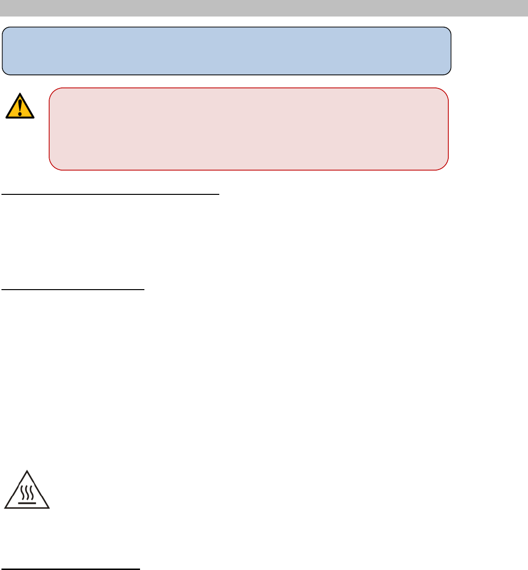
Please read the following guidelines carefully. Not following these guidelines can cause
harm to the gateway, yourself or other persons.
RF EXPOSURE WARNING
A minimum distance of 20cm must be maintained between the user's body
and the device antennas.

Modemulator User Guide
Page 9 of 120
not always clearly marked. They include fueling areas (petrol filling stations), below deck on boats, fuel or
chemical transfer or storage facilities and areas where the air contains chemicals or particles, such as
grain, dust, or metal powders. Do not transport or store your product in the compartment of a vehicle
which contains flammable gas, liquid or explosives.
Blasting Areas – Construction Sites
Turn off your product when in a blasting area in order to avoid interfering with two-way radios used in
blasting operations.
Do Not Use On Aircraft
Using wireless devices on aircraft can cause interference. Do not use it when the plane is on the ground
without permission from the aircraft crew.
Driving
Do not operate your device while driving. Park the vehicle first.
Medical Equipment
Do not use near medical equipment, especially life support equipment that might be susceptible to radio
interference.
ESD Notice
Electrostatic Discharge (ESD) is caused by a buildup of static electricity and can happen when making
contact with a product. To limit the likelihood of Electrostatic Discharge, it is recommended to:
avoid conditions that result in high static electricity (carpet, cool and dry air,…);
avoid touching any connectors when handling the unit; only touch the casing if possible;
ground yourself prior to handling by touching a large metal object.
In case the product encounters loss of performance after an Electrostatic Discharge, please reset the
device in order to restore it to normal functionality.
Class A Device
This is a Class A product. In a domestic environment this product may cause radio interference in which
case the User may be required to take adequate measures. The operation of the gateway is restricted for
use in a commercial, industrial or business environment.

Modemulator User Guide
Page 10 of 120
Chapter 1: Features
Introduction
The USRobotics Courier Modemulator allows a legacy M2M system to be conveniently converted to cellular
without upgrading or replacing application software. The Modemulator accepts and responds to analog
modem commands and sends result codes that mimic a PSTN connection, which allows drop-in
compatibility with legacy application software.
Overview of Main Features
The following features and capabilities assure an easy transition from dial-up to cellular M2M.
Cellular Gateway Engine
The Modemulator is embedded into a full-featured cellular gateway, and connects to cellular networks
using the gateway resources.
Operating Modes
The Modemulator operates in two distinct modes, which are selected by a MODE switch on the front of the
device.
Modemulator mode
Gateway mode
Modemulator Mode
In Modemulator mode, the Modemulator’s command line user interface emulates the behavior of a serial
dial-up modem connecting over the PSTN.
Modem AT command set
Originate or answer calls
PSTN response codes
Translate up to 7200 phone numbers into IP addresses
Cellular Gateway Mode
When in cellular gateway mode, the Modemulator configures the base unit to operate as a full-featured
cellular gateway. Some of the key gateway features are:
Interoperability with most cellular networks
GPS receiver
One 10/100 Mbps RJ45 Ethernet port
One DB9 RS-232 DCE serial port
IPsec VPN
Firewall
Graphical User Interface
Modemulator User Guide
Page 11 of 120
Automatic Switchover to Dial-up
To facilitate the gradual conversion of legacy systems to cellular or a permanently mixed system, the
Modemulator can initiate and answer connections over the PSTN to sites with a dial-up modem by
automatically diverting commands to a dial-up modem attached to its Modem serial port. This provides the
User a single interface and protocol for connecting with both cellular and dial-up sites.
Dial Security
The Modemulator provides three forms of dial security for your connections, similar to those of a dial-up
modem.
Programmable Login & Security Banners
The Modemulator can display a programmable login banner if Password Prompting is enabled, and display
a programmable warning banner to alert unauthorized Users, similar to those of a dial-up modem.
HELP Screens
The Modemulator displays screens that summarize the AT command set, Dial command options, and S-
register functions, similar to those of a dial-up modem.
Remote Access
The Modemulator settings can be configured remotely as well as locally, similarly to a dial-up modem.
Firmware Upgrades
The Modemulator firmware is upgradable locally or remotely, allowing easy access to the latest
Modemulator features and functions.

Modemulator User Guide
Page 12 of 120
Physical Features
1. WWAN Diversity Antenna Connector - SMA-female antenna port for connection to a diversity
antenna or a GPS antenna. See the USR3520/USR803520 Gateway User Guide for details.
2. Gateway LEDs – The seven Gateway LEDs indicate the operating status of the Gateway base unit.
See the USR3520/USR803520 Gateway User Guide for details.
3. Ethernet Port – 10/100 Mbps RJ-45. See the USR3520/USR803520 Gateway User Guide for details.
4. WWAN Main Antenna Connector - SMA-female antenna port for connection to a cellular antenna.
See the USR3520/USR803520 Gateway User Guide for details.
5. Terminal Serial Port - The terminal serial port provides an RS-232 asynchronous serial DCE
connection via a DB9-F connector. See Appendix J for pinout details. Use an appropriate serial cable to
connect this port to the DTE serial port of a terminal that will send modem AT commands to the
Modemulator. In gateway mode, this port is configured and activated by the Plugin tab of the gateway’s
graphical user interface.
6. Mode Switch – This switch selects the operating mode. See Table 1 below for details.
1
2
4
5
6
7
8
2
3

Modemulator User Guide
Page 13 of 120
7. Modemulator LEDs - These LEDs indicate the Modemulator operating mode and connection status.
See Table 1 for details.
CONNECT
LED
MODE
LED
Switch
Position
Modemulator
mode
Connected
Green
Green
←
Connection pending
(Originate or Answer)
Blinking
Green
←
Ready
Off
Green
←
Busy
Red
Green
←
Gateway mode
Off
Red
→
Power OFF
Off
Off
N/A
Table 1
8. Modem Serial Port - The modem serial port provides an RS-232 asynchronous serial DTE connection
via a DB9-M connector. See Appendix J for pinout details. Use an appropriate serial cable to connect this
port to the DCE serial port of a dial-up modem to enable the Modemulator to manage PSTN connections to
or from remote dial-up modems. In gateway mode, this port is inactive.
Modemulator User Guide
Page 14 of 120
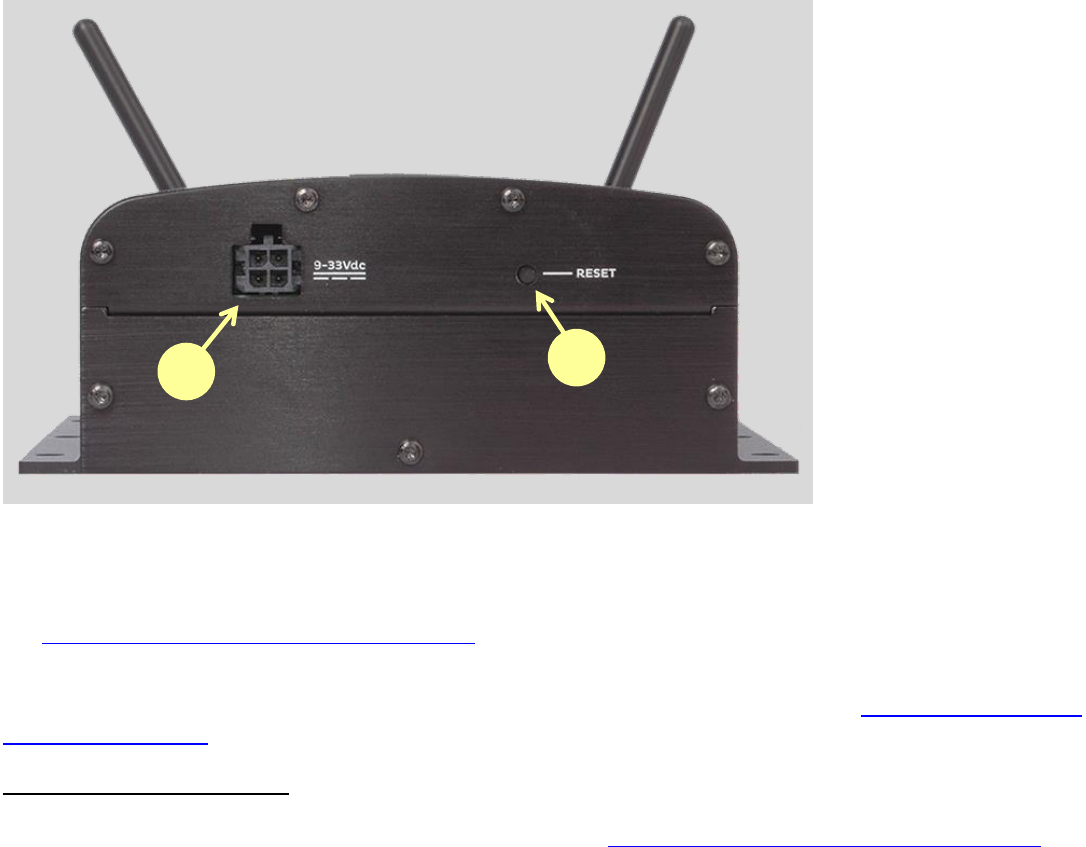
9. External Power Supply Input – This input receives operating power from the external low voltage
power supply that is included with the base unit. Connect the included power supply to this connector. See
the USR3520/USR803520 Gateway User Guide for details.
10. Reset Button - Press and hold for less than five seconds to reset the unit to the last working settings.
Press and hold for five seconds or more to reset the unit to factory settings. See the USR3520/USR803520
Gateway User Guide for details.
Mounting Instructions
The gateway can be mounted on a wall or DIN rail. See the USR3520/USR803520 Gateway User Guide for
details.
9
10

Modemulator User Guide
Page 15 of 120
Chapter 2: Getting Started
This chapter describes:
Verifying Modemulator Operation
Testing Modemulator Connectivity
For detailed configuration and advanced operating features see the Modemulator Command Reference
section in this guide, and see the USR3520/USR803520 Gateway User Guide.
Verifying Modemulator Operation
Because Modemulators make a peer-to-peer connection to another Modemulator, it is required to
perform this set-up procedure on two Modemulators.
For the USR3520/USR803520, please proceed directly to step 1.
For the USR3516-EMU upgrade kit, first follow the instructions in the USR3516-EMU Installation Guide to
upgrade a USR3510/USR803510 Gateway to a USR3520/USR803520.
1. Check system requirements:
Computer with an DB9 RS-232 serial port
Terminal emulation application that communicates with a COM port
If the computer does not have a serial port, use a USB-to-serial cable that is compatible with the
computer’s operating system.
2. Connect a computer to the Modemulator.
Use a DB9-to-DB9 serial cable to connect the computer’s serial port to the Modemulator Terminal
port.
Serial cables are widely available from electronics distributors and retailers.
3. Connect the included power supply unit (PSU) to the base unit.
Use the included PSU to power the base unit. Connect the PSU output jack to the power supply
input, and then plug the PSU into a mains power outlet.
The Modemulator will take about two minutes to become operational.

Modemulator User Guide
Page 16 of 120
MODE
4. Put the Modemulator into Modemulator mode by moving the MODE switch to the left if not already
there.
The MODE LED will be green when the Modemulator is switched into Modemulator mode.
5. Open a Terminal Emulation Application.
Open a terminal emulation window on the computer and select the COM port corresponding to the
computer’s serial port (usually COM1). Set the port parameters for 9600bps, 8 data bits, no parity,
1 stop bit.
Refer to the terminal emulation application documentation for details on setting parameters. It is
recommended to set the application’s font for Courier, Courier New, or another fixed character
width font to properly display the Modemulator screens.
6. Confirm communication with the Modemulator.
In the terminal emulation window, type AT<Enter>. The Modemulator should respond OK.

Modemulator User Guide
Page 17 of 120
Type ATI7<Enter>. The Modemulator should display the I7 information screen, as shown in
Figure 1. Actual parameter values may vary from Figure 1.
Figure 1
The Modemulator is now operational and ready to connect to the cellular network.
If the Modemulator does not respond to AT commands, remove power from the base unit and check the
Troubleshooting section.
ati7
USRobotics Courier EMU Configuration Profile...
Product type Modemulator
Product ID USR3516-EMU
Code Date 07/14/16
Code Rev 1.0.03
Modemulator S/N 1MENB2AP0001
Cellular S/N MB19D8K0LH
IMEI/MEID 356144040623593
IMSI 310410564600725
F/W Version m2m-1.46.0.2
S/W Version "USRobotics_V1.0.38"
Date/Time 2016-05-26/16:38:10
Internet State connected
WWAN Reg State registered
Operator AT&T
Carrier IP Addr 10.17.93.73
Signal Strength -74
ECIO -12
APN a105.2way.net
OK

Modemulator User Guide
Page 18 of 120
Testing Modemulator Connectivity
Because Modemulators make a peer-to-peer connection to another Modemulator, it is required to
perform this set-up procedure on two Modemulators.
System requirements
A computer with
o two DB9 RS-232 serial ports
o An Ethernet port
Terminal emulation application that communicates with COM ports
Web browser application
Or
Two computers, each with
o one DB9 RS-232 serial port
o An Ethernet port
Terminal emulation application that communicates with COM ports
Web browser application
If the computer does not have a serial port, use a USB-to-serial cable that is compatible with the
computer’s operating system.
Set Up Cellular Connectivity
1. Attach both of the included antennas to the antenna connectors on the front of the Modemulator.
2. Make sure that a cellular service plan is associated with the device (for CDMA networks) or with a
SIM card (for GSM networks).
Modemulator functionality requires a cellular service plan that has device-to-device IP routing.
This type is service is generally not available directly from Mobile Network Operators, so contact a
Mobile Virtual Network Operator (MVNO) to obtain a suitable service plan. See Appendix K for
details. Contact a USRobotics Sales representative for advice on finding a suitable service plan.
Preparing for GSM Networks
1. Remove power from the Modemulator.
2. Install the SIM (for GSM networks):
a. Remove the four Torx T6 screws from the top cover plate on the back of the unit and
remove the plate.

Modemulator User Guide
Page 19 of 120
The MVNO will provide a document listing the peer-to-peer static IP address assigned to this SIM.
Make note of this IP address for later use.
b. Insert the SIM into the SIM slot as shown in Figure 2.
Figure 2
c. Replace the top cover plate and its four TorxT6 screws.
Preparing for CDMA Networks
Devices connecting to a CDMA network do not require a SIM. After the MVNO has provisioned the data
service, the Modemulator will automatically activate itself onto the CDMA network.
The MVNO will provide a document listing the peer-to-peer static IP address assigned to this
device. Make note of this IP address for later use.
Connecting to the Cellular Network
1. Power up the Modemulator by plugging the provided power supply into the connector on the back
of the device.
The Modemulator will take about two minutes to become operational.
The Modemulator card uses the gateway resources for cellular connectivity. So the gateway must
be setup for cellular connectivity before using Modemulator functionality.
2. Use an Ethernet cable to connect the gateway’s Ethernet port to and a computer Ethernet port.
3. Open a web browser on the computer and enter the address 192.168.1.1 into the address bar.
Enter the default username (admin) and password (admin). After a successful login, the Home
screen will appear.

Modemulator User Guide
Page 20 of 120
4. Click on the “Interfaces” tab on the top menu bar and select 3G connection.
5. In the “General” section, select the radio firmware for the wireless service provider that you are
using. Click “Save changes”.
6. Verify/Update the gateway APN to match the network APN provided by the MVNO.
For GSM wireless service:
The network settings will populate automatically for many SIM cards. Check the settings of
the APN, Username, Password, and International Roaming. Update if necessary.
Click “Save changes”.
For CDMA service:
For both Verizon Wireless and Sprint services the activation will occur automatically.
Click on the “Home” tab on the top menu bar.
Connection to the network will be setup automatically.
7. Disconnect the Ethernet cable.
Configure Modemulator Dialing Directory
The Modemulator makes a peer-to-peer connection to another Modemulator, which emulates a
dial-up modem connecting to another dial-up modem. In both cases, the calling device has to
know the “number” of the answering device.
For an M2M system based on dial-up modems and PSTN networks, the telephone service provider
assigns a phone number to the destination, and the User (or software application) commands the
calling modem to dial the phone number of the destination modem.
For an M2M system based on Modemulators and cellular networks, the MVNO that provides the
cellular data service will assign a static IP address to each device (CDMA) or SIM (GSM) on the
account. That IP address is the “number” that the calling device must know.
In order for the Modemulator to be a drop-in replacement for dial-up modems, it has to accept a
command to dial a PSTN phone number, but translate that number into the IP address of the
destination Modemulator. That translation is done by the Modemulator dialing directory.
WARNING!
LAN to WAN routing is enabled by default. Once connected, any
Internet activity on your system will consume Cellular Data.
For configuration and more information go to Appendix B

Modemulator User Guide
Page 21 of 120
For this example, one Modemulator will be referred to as the “local” Modemulator, and the other will be
referred to as the “remote” Modemulator.
In this example, the local Modemulator’s dialing directory will be programmed to recognize the example
phone number 555-1234 and translate it into the IP address of the remote Modemulator.
Conversely, the remote Modemulator’s dialing directory will be programmed to recognize the example
phone number 555-5678 and translate it into the IP address of the local Modemulator.
Set-Up the Local Modemulator Dialing Directory
1. Power up the local Modemulator by plugging the provided power supply into the connector on the
back of the device, and then plug the PSU into a mains power outlet.
The Modemulator will take about two minutes to become operational.
2. Connect the local Modemulator Terminal port to a computer serial port. In the terminal application,
set this COM port for 9600bps, 8N1.
3. Consult the MVNO documentation for the static IP address assigned to the remote Modemulator
for CDMA networks or assigned to the SIM installed in remote Modemulator for GSM networks.
4. Enter the example phone number, port number (Modemulator listens to port 8888 by default), and
IP address (assigned by the MVNO) of the remote Modemulator into the local Modemulator’s
dialing directory by typing the following command into the local Modemulator, substituting the
static IP address assigned by the MVNO for the remote Modemulator:
AT{Y=5551234:8888:xxx.xxx.xxx.xxx <Enter>
Modemulator should respond OK.
5. Type the following command to set the local Modemulator to auto-answer on one ring:
ATS0=1 <Enter>
Modemulator should respond OK.
6. Keep the local Modemulator powered-up and connected to the computer serial port.
Set-Up the Remote Modemulator Dialing Directory
1. Power up the remote Modemulator by plugging the provided power supply into the connector on
the back of the device, and then plug the PSU into a mains power outlet.
phone
number
port
number
IP
address

Modemulator User Guide
Page 22 of 120
The Modemulator will take about two minutes to become operational.
2. Connect the remote Modemulator Terminal port to another computer serial port. In the terminal
application, set this COM port for 9600bps, 8N1.
3. Consult the MVNO documentation for the static IP address assigned to the local Modemulator for
CDMA networks or assigned to the SIM installed in local Modemulator for GSM networks.
4. Enter the example phone number, port number (Modemulator listens to port 8888 by default), and
IP address (assigned by the MVNO) of the local Modemulator into the remote Modemulator’s
dialing directory by typing the following command into the remote Modemulator, substituting the
static IP address assigned by the MVNO for the local Modemulator:
AT{Y=5555678:8888:xxx.xxx.xxx.xxx <Enter>
Modemulator should respond OK.
5. Type the following command to set the remote Modemulator to auto-answer on one ring:
ATS0=1 <Enter>
Modemulator should respond OK.
6. Keep the remote Modemulator powered-up and connected to the computer serial port.
Making a Connection
With connectivity and dialing directories now set-up, follow the steps below to make a Modemulator test
connection.
1. Type the following command to the local Modemulator to initiate a connection to the remote
Modemulator:
ATD5551234 <Enter>
The local Modemulator will take a few moments to make a connection to the remote
Modemulator.
The local Modemulator should first report RINGING, then CONNECT 9600.
The remote Modemulator should first report RING, then CONNECT 9600.
2. Test the data transfer:
Type characters into the local terminal. A few moments later the characters should appear on
the remote terminal.
phone
number
port
number
IP
address
Modemulator User Guide
Page 23 of 120
Type characters into the remote terminal. A few moments later the characters should appear
on the local terminal.
3. Drop the connection by using one of these two methods:
Type the escape sequence +++ into the local terminal to drop the connection. The local
Modemulator should then respond NO CARRIER.
Using the local terminal capabilities, de-assert the RS-232 DTR signal to drop the connection.
The local Modemulator should respond NO CARRIER. Then re-assert DTR to allow further
communication.
The Modemulators are now operational and ready to install.

Modemulator User Guide
Page 24 of 120
Chapter 3: Applications
This chapter summarizes how to:
Convert a legacy dial-up M2M system to cellular
Maintain compatibility with dial-up modems
For detailed configuration and advanced operating features see the Modemulator Command Reference
section in this guide, and see the USR3520/USR803520 Gateway User Guide.
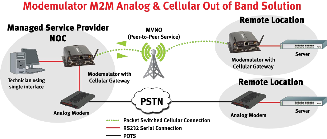
Convert A Legacy Dial-up M2M System To Cellular
Properly configured Modemulators are drop-in cellular replacements for dial-up PSTN modems, which
extends the useful life of legacy M2M software and hardware, while providing the benefits of a transition
from the PSTN to the cellular network.
Modemulators normally operate in a peer-to-peer fashion, with a Modemulator on both ends of a
connection. Alternatively, the Modemulator can operate in single-ended mode for a system that has
remote Modemulators connecting directly with a TCP/IP server. Both types of systems are described
below.
Peer-to-Peer Operation
First, follow the Getting Started chapter in this guide to verify that two Modemulators are operating
properly.
System Architecture
A legacy M2M host site (Headquarters, Operations Center, etc.) is the source of data being transferred to
all of the remote sites, or is the destination of data being transferred from all of the remote sites. This
host site has application hardware and software that normally interfaces with a serial dial-up modem used
to transfer the data.
The legacy M2M remote sites are the sources of data being transferred to a host site, or are the
destinations of data being transferred from a host site. Each remote site has application hardware and
software that normally interfaces with a serial dial-up modem used to transfer the data.
The Terminal port of the Modemulator at the host site connects to a serial port of the host application
hardware that would normally connect to a serial dial-up modem, and the Terminal port of the
Modemulator at each remote site connects to a serial port of the remote application hardware that would
normally connect to a serial dial-up modem.
An RF survey of the host and remote sites may be necessary to determine if the installations are
in range of cellular reception from the operator chosen to provide service. Consult a professional
cellular installer for assistance.

Modemulator User Guide
Page 25 of 120
Set-Up the Host Modemulator
The Modemulator defaults to peer-to-peer mode, which allows the host Modemulator to initiate a
connection to any remote Modemulator or any remote Modemulator to initiate a connection to the host
Modemulator.
The Modemulator that interfaces to the host application software must be configured as required by the
software with the same settings as a dial-up modem. The application software may automatically send
initialization commands to the modem, or may require the modem to be pre-configured. Consult the
application software User Guide for any requirements for pre-configuring the attached modem.
If the application software User Guide is not available, modem configuration settings can normally
be read directly from the dial-up modem. See the modem User Guide for details. Those settings
can then be referenced when pre-configuring the Modemulator.
Choose an arbitrary phone number for each remote Modemulator. For drop-in compatibility with the host
software, use the phone numbers that the host software is already programmed to dial. Program the
host Modemulator’s dialing directory with the static IP address of each remote Modemulator and the
corresponding phone number.
Disconnect the dial-up modem from the application hardware serial port, and connect the Modemulator to
the application hardware serial port. The application hardware will now use the Modemulator for all
communications.
Set-Up Each Remote Modemulator
The Modemulator defaults to peer-to-peer mode, which allows the host Modemulator to initiate a
connection to any remote Modemulator or any remote Modemulator to initiate a connection to the host
Modemulator.
The Modemulator that interfaces to the remote application software must be configured as required by
the software with the same settings as a dial-up modem. The application software may automatically send
initialization commands to the modem, or may require the modem to be pre-configured. Consult the
application software User Guide for any requirements for configuring the attached modem.
If the application software User Guide is not available, modem configuration settings can be read
directly from the dial-up modem. See the modem User Guide for details. Those settings can then
be referenced when pre-configuring the Modemulator.
Choose an arbitrary phone number for the host Modemulator. For drop-in compatibility with the remote
software, use the phone number that the remote software is already programmed to dial. Program each
remote Modemulator’s dialing directory with the static IP address of the host Modemulator and the
corresponding phone number.

Modemulator User Guide
Page 26 of 120
Disconnect the dial-up modem from the application hardware serial port, and connect the Modemulator to
the application hardware serial port. The application hardware will now use the Modemulator for all
communications.
Outgoing Calls
In a peer-to-peer system the host Modemulator or any remote Modemulator may initiate a connection.
To initiate a connection from an originating Modemulator to an answering Modemulator, a dial
command is sent by the legacy software to the originating Modemulator. The originating Modemulator
will search its dialing directory for an entry containing the phone number from that dial command.
If an entry for that phone number is found in the dialing directory, the originating Modemulator
will open an IP connection to the IP address of the answering Modemulator. The originating
Modemulator and the answering Modemulator will then send call-progress messages to the legacy
application software that mimic those of a dial-up modem. If the answering Modemulator is
configured to auto-answer or if the application software issues an answer command, the connection
will complete, which emulates the behavior of dial-up modems.
If the answering Modemulator does not auto-answer or manually answer, the connection will
time-out, which emulates the behavior of dial-up modems.
The originating Modemulator will report NO DIALTONE or BUSY or NO CARRIER if the answering
Modemulator already has a connection in-progress with another Modemulator.
The originating Modemulator will report NOT FOUND if an entry for that phone number is not
found in the dialing directory, and a dial-up modem is not attached or not available. See Maintain
Compatibility With Dial-up Modems for information about attaching a dial-up modem to a
Modemulator.
If an entry for that phone number is not found in the dialing directory, and a dial-up modem is
attached and available, the originating Modemulator will forward the dial command to the
attached dial-up modem which will dial the number via the PSTN. See Maintain Compatibility With
Dial-up Modems for information about attaching a dial-up modem to a Modemulator.
The legacy software sends the same type of command to initiate both cellular and analog connections, and
receives the same type of responses. This makes the type of connection indistinguishable and transparent
to the legacy software.
Incoming Calls
In a peer-to-peer system the host Modemulator or any remote Modemulator may answer a connection.
Incoming cellular calls will route through the answering Modemulator’s Terminal port to the legacy
application software when a connection completes.
If the answering Modemulator does not have a cellular connection already in-progress with
another Modemulator, the answering Modemulator will accept the IP connection from the
originating Modemulator. The originating Modemulator and the answering Modemulator will

Modemulator User Guide
Page 27 of 120
then send call-progress messages to the legacy application software that mimic those of a dial-up
modem. If the answering Modemulator is configured to auto-answer or if the application software
issues an answer command, the connection will complete, which emulates the behavior of dial-up
modems.
If the answering Modemulator does not auto-answer or manually answer, the connection will
time-out, which emulates the behavior of dial-up modems.
If the answering Modemulator has a cellular connection already in-progress with another
Modemulator, the current connection will not be interrupted and the originating Modemulator will
report NO DIALTONE or BUSY or NO CARRIER.
The following diagram illustrates a simplified peer-to-peer legacy system using two Modemulators and
peer-to-peer cellular service.
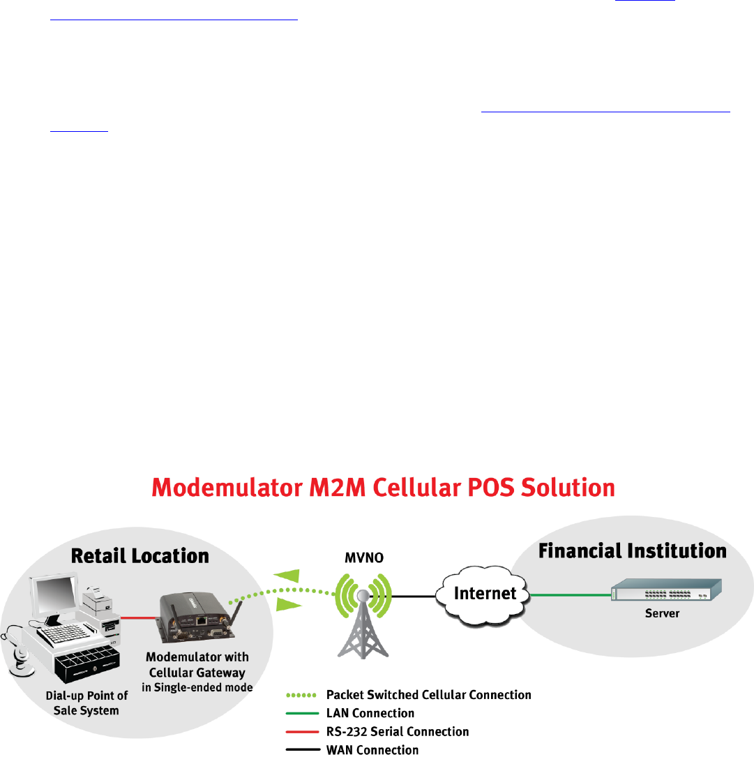
Single-Ended Operation
First, follow the Getting Started chapter in this guide to verify that one Modemulator is operating properly.
System Architecture
A legacy M2M host site (Headquarters, Operations Center, Transaction Processor) is the destination of
data being transferred from all of the remote sites. This host site has application hardware and software
that interfaces with the Internet to accept an IP connection and transfer the data.
The legacy M2M remote sites are the sources of data being transferred to the host site. Each remote
site has application hardware and software that normally interfaces with a serial dial-up modem used to
transfer the data.
Modemulators can replace the dial-up modems at all or some of the remote sites. The Terminal port of
the Modemulator at each remote site connects to a serial port of the remote application hardware that
would normally connect to a serial dial-up modem.

Modemulator User Guide
Page 28 of 120
An RF survey of the remote sites may be necessary to determine if the installations are in range
of cellular reception from the operator chosen to provide service. Consult a professional cellular
installer for assistance.
Set-Up Each Remote Modemulator
The Modemulator defaults to peer-to-peer mode, but for a single-ended system it must be configured for
single-ended operation. Single-ended operation is enabled by issuing the {M1 command. See the
Command Reference chapter of this document for details.
The Modemulator that interfaces to the remote application software must be configured as required by
the software with the same settings as a dial-up modem. The application software may automatically send
initialization commands to the modem, or may require the modem to be pre-configured. Consult the
application software User Guide for any requirements for configuring the attached modem.
If the application software User Guide is not available, modem configuration settings can be read
directly from the dial-up modem. See the modem User Guide for details. Those settings can then
be referenced when pre-configuring the Modemulator.
Choose an arbitrary phone number for the host server. For drop-in compatibility with the remote
software, use the phone number that the remote software is already programmed to dial. Program each
remote Modemulator’s dialing directory with the IP address of the host server and the corresponding
phone number.
Disconnect the dial-up modem from the application hardware serial port, and connect the Modemulator to
the application hardware serial port. The application hardware will now use the Modemulator for all
communications.
Modemulator Outgoing Calls
In a single-ended system the host is a TCP/IP server, and any remote Modemulator may initiate a
connection.
To initiate a connection from a remote Modemulator to the host, a dial command is sent by the legacy
software to the remote Modemulator. The remote Modemulator will search its dialing directory for an
entry containing the phone number from that dial command.
If an entry for that phone number is found in the dialing directory, the remote Modemulator will
open an IP connection to the IP address of the host. The remote Modemulator will then send call-
progress messages to the legacy application software that mimic those of a dial-up modem. If the
host accepts the IP session, the connection will complete, which emulates the behavior of dial-up
modems.
If the host does not accept the IP session, the connection will time-out, which emulates the
behavior of dial-up modems.
Modemulator User Guide
Page 29 of 120
The remote Modemulator will report NOT FOUND if an entry for that phone number is not found in
the dialing directory, and a dial-up modem is not attached or not available. See Maintain
Compatibility With Dial-up Modems for information about attaching a dial-up modem to a
Modemulator.
If an entry for that phone number is not found in the dialing directory, and a dial-up modem is
attached and available, the remote Modemulator will forward the dial command to the attached
dial-up modem which will dial the number via the PSTN. See Maintain Compatibility With Dial-up
Modems for information about attaching a dial-up modem to a Modemulator.
The legacy software sends the same type of command to initiate the cellular connection as it does for an
analog connection, and receives the same type of responses. This makes the cellular connection
indistinguishable from an analog connection to the legacy software.
Modemulator Incoming Calls
In a single-ended system that uses conventional cellular service, the host will be unable to initiate a
connection to the remote Modemulators because of constraints in the cellular network, unless a VPN
tunnel or public static IP address is used.
The cellular service provider normally assigns dynamic IP addresses to the cellular devices, which
prevents the host from knowing the current IP address of the remote Modemulators.
The cellular service provider may have a firewall preventing any host from contacting the IP
address of any cellular devices.
The following diagram illustrates a simplified single-ended legacy system using one Modemulator and
conventional client/server cellular service.

Modemulator User Guide
Page 30 of 120
Maintain Compatibility with Dial-up Modems
The host Modemulator of a peer-to-peer system can utilize an attached serial dial-up modem for
connections with remote dial-up modems via the PSTN. This section describes a system that has a
mixture of remote Modemulators and remote dial-up modems.
A mixed cellular / dial-up system requires:
Cellular peer-to-peer service for the host Modemulator and remote Modemulators
PSTN service at the host site and at all remote dial-up sites
A serial dial-up modem attached to the host Modemulator at the host site
A dial-up modem attached to the remote application hardware at each remote dial-up site
Follow the set-up for peer-to-peer operation to program the host Modemulators dialing directory with IP
addresses for the remote Modemulators.
Do not enter the PSTN phone number of any remote dial-up site into the host Modemulators
dialing directory.
The host Modemulator can initiate or answer PSTN connections by using an attached serial dial-up
modem. Also, any configuration commands sent to the Modemulator are processed by both the
Modemulator and by the attached modem. In that way, modem initialization strings sent by legacy
software will apply to both the Modemulator and the dial-up modem.
Outgoing PSTN Calls
For a PSTN connection to be initiated, a dial command is sent to the host Modemulator by the legacy
software. The host Modemulator will search its dialing directory for an entry containing the phone
number in the dial command.
If no entry is found for that phone number, the dial command will be forwarded to the attached
dial-up modem which will dial that phone number via the PSTN, allowing the legacy software to
contact any remote dial-up site.
The host Modemulator will report NOT FOUND if a PSTN phone number is dialed and a dial-up
modem is not attached or not available based on the RS232 CTS signal.
The legacy software sends the same type of dial command to initiate either cellular or PSTN connections,
and receives the same type of responses. This makes the type of connection indistinguishable and
transparent to the legacy software.
Modemulator User Guide
Page 31 of 120
Incoming Calls
Incoming PSTN calls or incoming cellular calls will route through the host Modemulator’s Terminal port to
the legacy application software when a connection completes.
If the host Modemulator has a cellular connection already in-progress with a remote
Modemulator, the host Modemulator will de-assert the RS-232 DTR signal to the attached dial-up
modem to prevent the attached dial-up modem from answering an incoming PSTN call.
If the host Modemulator has a PSTN connection already in-progress with a remote dial-up modem
and a remote Modemulator attempts to contact the host Modemulator, the remote Modemulator
will report NO DIALTONE.
If the host Modemulator has a cellular connection already in-progress with a remote
Modemulator, and another remote Modemulator attempts to contact the host Modemulator, the
remote Modemulator will report NO DIALTONE or BUSY or NO CARRIER.
The following diagram illustrates a simplified peer-to-peer legacy system using two Modemulators, cellular
peer-to-peer service, two dial-up modems, and PSTN service.
Modemulator User Guide
Page 32 of 120
Chapter 4: Command Reference
This section includes information about:
Using the AT Command Set
Modemulator Memory
AT Command Reference Guide
Using the AT Command Set
Overview
If Modemulator mode is enabled by the Mode switch on the front panel, and if no connection is in-
progress, AT commands can be sent to the Modemulator Terminal port to change Modemulator settings.
To send AT commands to the Modemulator, run a terminal emulation application on a computer,
configured so the selected COM port sends whatever is typed to the computer RS-232 serial port that is
attached to the Modemulator. By default, the Modemulator will echo commands back to the terminal.
General rules for using AT commands
Here are some general guidelines for sending AT commands to the Modemulator:
Type AT before each command and press ENTER after each command.
The exceptions are A/ and +++, which require neither AT nor ENTER.
Leave zeroes off the end of AT commands. A missing numeric parameter is assumed to be a zero. For
example, ATE is equivalent to ATE0.
Either use AT (all caps) or at (all lower case). Mixed case, as in At for example, is unacceptable.
Create compound commands of up to 58 characters between AT and ENTER.
Example: AT&H1 D(847)555-1234
AT Attention; a command follows.
&H1 Enable hardware flow control.
D Dial the following number.
Optional hyphens, spaces, and parentheses add to the count of 58 characters.
Commands not recognized will be accepted and ignored.

Modemulator User Guide
Page 33 of 120
Modemulator Memory
This section describes the types of memory that are included in the Courier Modemulator & M2M Gateway,
what the memory is used for, and where the memory is located.
The Modemulator Base Unit
The Courier Modemulator & M2M Gateway base unit contains Random Access Memory (RAM) and Flash
memory. These memories hold the operating system, radio firmware, system firmware, and application
software that control the operation of the base unit. The system firmware and the application software are
user-upgradable. See the USR3520/USR803520 Gateway User Guide or the USR3516-EMU Installation
Guide for details on loading new system firmware and application software into the base unit.
The Modemulator Expansion Card
The USR3516-EMU expansion card that is installed into the Courier Modemulator & M2M Gateway contains
three types of memory that users can interact with: Random Access Memory (RAM), NonVolatile Random
Access Memory (NVRAM), and Flash memory.
Random Access Memory
The RAM holds the current settings that control the Modemulator card operation. These settings are
recalled from NVRAM and loaded into the RAM on power-up or when the Modemulator receives an ATZ
command. Commands sent to the Modemulator to change settings will modify the RAM parameters only.
The settings must be saved into NVRAM to make the new settings nonvolatile. The commands to display
and manage the Modemulator card settings are detailed in the AT Command Reference Guide section in
this guide.
Nonvolatile Random Access Memory
The Modemulator card uses Electrically Erasable Programmable Read Only Memory (EEPROM) for
nonvolatile storage. This NVRAM is used to hold Modemulator card settings that are recalled to RAM on
power-up or when the Modemulator receives an ATZ command, and also holds the Modemulator card
dialing directory, security accounts, and security banners. The commands to display and manage the
Modemulator card NVRAM are detailed in the AT Command Reference Guide section in this guide.
Flash Memory
The Modemulator card firmware is stored in the Modemulator card Flash memory, which is another type of
nonvolatile storage. This firmware includes factory defaults that can be recalled by sending AT&F0,
AT&F1, or AT&F2 commands. See the AT Command Reference Guide section in this guide for details. The
firmware stored in the Modemulator card Flash memory is user-upgradable. See Appendix I in this guide
for details on loading new Modemulator card firmware into Flash memory.

Modemulator User Guide
Page 34 of 120
AT Command Reference Guide
'*' denotes command available in Remote Command Mode. (See the {R1 command)
Basic Commands
AT$ * Display Basic Command Help Screen:
This command will not be forwarded to the analog modem.
A/ * Repeat Last Command
This command will repeat the last AT command string attempted. If the last AT command ended in
DL, then "ERROR" will be displayed.
This command will not be forwarded to the analog modem.
at$
Basic Command Help (unrecognized commands accepted & ignored)
D$ Dial Command Help I1 Main Checksum
&$ Ampersand Command Help I3 Product Type & Version
{$ Modemulator Command Help I4 RAM Variables
S$ S-Register Command Help I5 EEPROM Variables
I6 Link Diagnostics
!! Flash New Code I7 Product Profile
A/ Repeat Last Command O Return Online
A Manual Answer Q0 Display Result Codes
Q1 Quiet Mode
E0 Command Echo Off
E1 Command Echo On V0 Numeric Result Codes
V1 Verbal Result Codes
F0 Local Online Echo On
F1 Local Online Echo Off X0-7 Result Code Options
H Hang Up Z Recall EEPROM Variables
OK

Modemulator User Guide
Page 35 of 120
A Manual Answer
This must be the last command in the AT command string.
This command would be used to answer an incoming call when autoanswer is disabled. The
command would be issued by the User, or by an application when the RING message is received,
or when the Ring Indicate (RI) signal goes active on the RS-232 interface.
D$ Dial Command Help Screen:
This command will not be forwarded to the analog modem.
Dn Dial (n=phone number)
This must be the last command in the AT command string.
Dial modifier characters (except comma, colon, and L) in dial commands that initiate cellular
connections are ignored. Dial modifier characters in dial commands that are forwarded to an
attached dial-up modem are processed by the modem.
Use this command as you would for an ordinary analog modem. There are two cases:
atd$
Dial Command Help (unrecognized commands accepted & ignored)
D:IP:Port Direct IP Dialing
D:IP Direct IP Dialing if Port=8888
DL Dial Last Number
Dn Dial Phone Number n
, Dial Modifier for Pause (S8 seconds)
OK

Modemulator User Guide
Page 36 of 120
1. The dialing directory is searched for an entry containing the phone number n and a match is
found. (see the {Y command). In this case, the legacy analog phone number (or any number of
your choosing) is translated into the Port number and IP address in the directory entry, and
used to create a TCP client connection to the remote TCP server (Listener).
Example: ATD3456789
(The remote analog modem with this phone number was replaced by a Modemulator, and {Y
was used to translate the number to a Port/IPaddress)
Example: ATDT4
(The {Y command was used to create an entry having the phone number 4, with the associated
Port/IPaddress of the new remote Modemulator)
This is equivalent to ATD4 since the 'T' dial modifier is ignored.
2. The dialing directory is searched for an entry containing the phone number n and a match is
not found. In this case, the entire AT command string is forwarded to the connected analog
modem (if present), and an ordinary analog modem connection is attempted. If no analog
modem is attached, the NOT FOUND message is displayed.
To forward only the dial string portion, but not the configuration commands, issue the {F1
command.
Example: ATDT18005551234
(a remote analog modem's phone number)
The following commands are not forwarded to the analog modem:
$ (Help) commands
I (Info) commands
{ (Modemulator-only) commands
&C0 (force DCD) command
A/ (repeat last command)
If a command string is to be forwarded to the analog modem, any of the above commands should
be grouped at the end of the configuration commands, and before the Dial command, if present.
DL Dial Last Number
This must be the last command in the AT command string.
Modemulator User Guide
Page 37 of 120
Redial the last phone number attempted. It proceeds as in the cases described in the Dn or D:
commands.
DSn Dial Stored Number
Since the 'S' in ATDSn is ignored as a non-implemented dial modifier, Dial Stored Number
commands can be emulated. The USRobotics Courier analog modem allows stored numbers in
locations 0 through 79, so to emulate a stored phone number with the Modemulator, simply assign
a phone number in the Modemulator dialing directory equal to the legacy storage location index.
Example: AT{Y=2::172.17.2.1
(Stores the phone number 2, the default port number, and the IP address into the
Modemulator dialing directory)
ATDS2
(Dials the stored number 2, where 2 was formerly the location of the stored number
in the analog modem)
D:i:p Direct IP Dialing (i=destination IP address, p=destination port number)
This must be the last command in the AT command string.
Bypass the directory lookup, and attempt to create the TCP client connection directly, using the IP
address and port number supplied in the command.
Separate the ATD, IP address, and Port number with ':' (colon) characters.
Example: ATD:172.17.2.1:2025
If using the default Listener port number (8888) on the answering Modemulator, you may
optionally omit the port number.
Example: ATD:172.17.2.1
One advantage of using direct IP dialing is that it doesn't use the dialing directory, so the number
of remotes is unlimited. The dialing directory is limited to 7200 entries.
E0 * Command Echo OFF
Disable local echo of typed characters.
E1 * Command Echo ON (default)
Enable local echo of typed characters.
F0 * Local Online Echo ON
Enable local echo of typed characters in a data connection.

Modemulator User Guide
Page 38 of 120
This is sometimes known as half-duplex mode.
F1 * Local Online Echo OFF (default)
Disable local echo of typed characters in a data connection.
This is sometimes known as full-duplex mode.
H * Hang Up
This must be the last command in the AT command string.
Disconnect the local TCP client from Remote Command Mode (see the {R1 command) and cause
both Modemulators to report NO CARRIER.
I1 * Display Checksum
Display the Modemulator firmware's 4 digit hex checksum (used mainly by tech support).
Example:
This command will not be forwarded to the analog modem.
ati1
9225
OK

Modemulator User Guide
Page 39 of 120
I3 * Display Product Type and Version
Display the product description and the firmware version number.
Example:
This command will not be forwarded to the analog modem.
ati3
USRobotics Courier EMU V1.0.03
OK

Modemulator User Guide
Page 40 of 120
I4 * Display RAM Variables
Display the current settings of RAM variables. This screen is formatted to be similar to a
USRobotics Courier Dial-up Business Modem.
Example:
This command will not be forwarded to the analog modem.
ati4
USRobotics Courier EMU Settings...
BAUD=9600 PARITY=N WORDLEN=8
E1 F1 Q0 V1 X7
&A3 &C1 &D2 &H1 &I0 &L0 &R2 &S0
{C0 {D0 {F0 {H0 {J0 {M0 {O0 {R0
S00=000 S01=000 S02=043 S07=060 S08=002 S19=000 S21=010
S22=017 S23=019 S25=002 S44=015 S59=000 S60=020 S61=120
S64=060 S65=015
LAST DIALED #: 18478742000
OK

Modemulator User Guide
Page 41 of 120
I5 * Display NVRAM Variables
Display the current settings of variables stored in EEPROM. This screen is formatted to be similar to
a USRobotics Courier Dial-up Business Modem.
Example:
This command will not be forwarded to the analog modem.
ati5
USRobotics Courier EMU NVRAM Settings...
BAUD=115200 PARITY=N WORDLEN=8
E1 F1 Q0 V1 X7
&A3 &C1 &D2 &H1 &I0 &L0 &R2 &S0
{C0 {D0 {F0 {H0 {J0 {M0 {O0 {R0
S00=000 S02=043 S07=060 S08=002 S19=000 S21=010 S22=017
S23=019 S25=002 S44=015 S59=000 S60=020 S61=120 S64=060
S65=015
OK

Modemulator User Guide
Page 42 of 120
I6 * Display Link Diagnostics
Display the link diagnostic information for the last connection (or current connection if in Remote
Command Mode - see the {R1 command).
Example:
Chars Sent TXD characters sent to remote Modemulator.
Chars Rcvd RXD characters received from remote Modemulator.
Max Latency (See S61 for description)
(Blank in Single-Ended mode)
(Blank if remote heartbeat period is zero)
Last Call Duration of call in days:hrs:min:sec.
(Labeled "Current Call" if in Remote Command Mode)
Disconnect Reason (See Appendix E for a list)
ati6
USRobotics Courier EMU Link Diagnostics...
Chars Sent 0
Chars Rcvd 0
Max Latency (sec) 000
Last Call 000:00:00:00
Disconnect Reason is DTR dropped
OK

Modemulator User Guide
Page 43 of 120
This command will not be forwarded to the analog modem.
I7 * Display Configuration Profile
Display information about the product.
Example:
This command will not be forwarded to the analog modem.
O * Return Online
This must be the last command in the AT command string.
Exit Remote Command Mode (see the {R1 command) and return to ordinary data connection.
The CONNECT message will report the DTE speed of the answer side.
ati7
USRobotics Courier EMU Configuration Profile...
Product type Modemulator
Product ID USR3516-EMU
Code Date 07/14/16
Code Rev 1.0.03
Modemulator S/N 1MENB2AP0001
Cellular S/N MB19D8K0LH
IMEI/MEID 356144040623593
IMSI 310410564600725
F/W Version m2m-1.46.0.2
S/W Version "USRobotics_V1.0.38"
Date/Time 2016-05-26/16:38:10
Internet State connected
WWAN Reg State registered
Operator AT&T
Carrier IP Addr 10.17.93.73
Signal Strength -74
ECIO -12
APN a105.2way.net
OK
Not shown while in Remote Command mode

Modemulator User Guide
Page 44 of 120
Q0 * Display Result Codes (default)
Enable the display of result codes (verbal or numeric).
(See Appendix D for a description of result codes)
Q1 * Quiet Mode
Disable the display of result codes (verbal and numeric).
V0 * Numeric Result Codes
Replace verbal result codes with numeric codes.
(See Appendix D for a description of result codes)
V1 * Verbal Result Codes (default)
Use verbal result codes.
(See Appendix D for a description of result codes)
Xn * Result Code Options (default=X7)
Result Code Options:
X0
X1
X2
X3
X4
X5
X6
X7
0/OK
*
*
*
*
*
*
*
*
1/CONNECT
*
*
*
*
*
*
*
*
2/RING
*
*
*
*
*
*
*
*
3/NO CARRIER
*
*
*
*
*
*
*
*
4/ERROR
*
*
*
*
*
*
*
*
6/NO DIAL TONE
*
*
*
*
7/BUSY
*
*
*
*
*
8/NO ANSWER
*
*
*
*
*
10/REFUSED
*
*
*
*
*
*
*
*
11/RINGING
*
*
*
The local DTE speed is appended to the CONNECT message.
(See Appendix D for a description of result codes)

Modemulator User Guide
Page 45 of 120
Z * Recall NVRAM Variables
This must be the last command in the AT command string.
Recall all stored variables from EEPROM and copy to RAM.
Settings for the following RAM variables are stored in EEPROM:
E F Q V X
&A &C &D &H &I &L &R &S
{C {D {F {H {J {M {O {R
S0 S2 S7 S8 S19 S21 S22 S23 S25 S44 S59 S60 S61 S64 S65
(See &W command for storing variables in EEPROM)
!! * Flash New Modemulator Code
This must be the last command in the AT command string.
(See Appendix I Procedure for Flashing New Firmware into Modemulator)

Modemulator User Guide
Page 46 of 120
Ampersand Commands
&$ * Display Ampersand Command Help Screen:
This command will not be forwarded to the analog modem.
&A0 * Basic CONNECT Message
If the programmable CONNECT message is empty, then upon connection, emulate the basic
CONNECT message.
Example:
CONNECT 33600
at&$
Ampersand Command Help (unrecognized commands accepted & ignored)
&A0 CONNECT n &I0 S/W Recv Flow Ctrl Disabled
&A1 CONNECT n/ARQ &I1 Xon/Xoff Signals Local & Remote
&A2 CONNECT n/ARQ/V34 &I2 Xon/Xoff Signals Local Only
&A3 CONNECT n/ARQ/V34/LAPM/V42BIS
&L0 Normal Line
&C0 CD Override &L1 Leased Line
&C1 CD Normal
&R1 Modem Ignores RTS
&D0 DTR Override &R2 RTS Controls RXD Out
&D2 DTR Normal
&S0 DSR Override
&F0 Factory (no flow) &S1 DSR Follows CD
&F1 Factory (H/W flow)
&F2 Factory (S/W flow) &W Save Settings to EEPROM
&H0 Flow Ctrl Disabled
&H1 Flow Ctrl H/W
&H2 Flow Ctrl S/W
OK

Modemulator User Guide
Page 47 of 120
&A1 * ARQ CONNECT Message
If the programmable CONNECT message is empty, then upon connection, emulate the ARQ
CONNECT message.
Example:
CONNECT 33600/ARQ
&A2 * Modulation CONNECT Message
If the programmable CONNECT message is empty, then upon connection, emulate the ARQ and
modulation CONNECT message.
Example:
CONNECT 33600/ARQ/V34
&A3 * Compression CONNECT Message (default)
If the programmable CONNECT message is empty, then upon connection, emulate the ARQ,
modulation and compression CONNECT message.
Example:
CONNECT 33600/ARQ/V34/LAPM/V42BIS
&C0 * CD Override
Assert the DCD signal on the RS-232 interface for DTE applications that require it.
This command will not be forwarded to the analog modem.
&C1 * CD Normal Operation (default)
The DCD signal on the RS-232 interface behaves normally. If the Modemulator is currently in a
cellular or analog connection, the DCD signal will be asserted.
&D0 * DTR Override
If the local DTE does not provide the DTR signal on the RS-232 interface, the Modemulator
firmware can behave as if DTR is asserted with this command.
&D2 * DTR Normal Operation (default)
The DTR signal on the RS-232 interface behaves normally. If the Modemulator is currently in a
cellular or analog connection, and the DTR signal is de-asserted, the connection will be terminated.
Be sure to re-assert DTR before the next connection attempt.
Modemulator User Guide
Page 48 of 120
&F0 * Set Factory Defaults - no flow ctrl
Equivalent to sending AT&F1 X1 &H0 &R1
(See Factory Defaults Table below)
&F1 * Set Factory Defaults - H/W flow ctrl (as shipped from factory)
(See Factory Defaults Table below)
&F2 * Set Factory Defaults - S/W flow ctrl
Equivalent to sending AT&F1 &H2 &I2 &R1
(See Factory Defaults Table below)

Modemulator User Guide
Page 49 of 120
Factory Defaults Table:
Parameter
&F0
&F1
&F2
Parameter
&F0
&F1
&F2
E
1
1
1
{O
0
0
0
F
1
1
1
{R
0
0
0
Q
0
0
0
S0
000
000
000
V
1
1
1
S2
043
043
043
X
1
7
7
S7
060
060
060
&A
3
3
3
S8
002
002
002
&C
1
1
1
S19
000
000
000
&D
2
2
2
S21
010
010
010
&H
0
1
2
S22
017
017
017
&I
0
0
2
S23
019
019
019
&L
0
0
0
S25
002
002
002
&R
1
2
1
S44
015
015
015
&S
0
0
0
S59
000
000
000
{C
0
0
0
S60
020
020
020
{D
0
0
0
S61
120
120
120
{F
0
0
0
S64
060
060
060
{H
0
0
0
S65
015
015
015
{J
0
0
0
{M
0
0
0

Modemulator User Guide
Page 50 of 120
&H0 * Flow Control Disabled
No Hardware or Software flow control will be used.
(See Appendix F Flow Control)
&H1 * H/W Flow Control (default)
Hardware flow control (CTS/RTS) will be used.
(See Appendix F Flow Control)
&H2 * S/W Flow Control
Software flow control (Xon/Xoff) will be used.
(See Appendix F Flow Control)
&I0 * S/W Receive Flow Control Disabled (default)
Xon and Xoff characters received from the local DTE are treated as ordinary data.
(See Appendix F Flow Control)
&I1 * Xon/Xoff Signals Local and Remote Modemulator
Xon and Xoff characters received from the local DTE control the flow of data to the DTE and
Xon/Xoff characters are also passed along to the remote Modemulator as data.
(See Appendix F Flow Control)
&I2 * Xon/Xoff Signals Local Modemulator Only
Xon and Xoff characters received from the local DTE control the flow of data to the DTE, but are
not passed along to the remote Modemulator as data.
(See Appendix F Flow Control)
&L0 * Normal Line (default)
Emulate normal PSTN dialup operation.
(See Appendix L Leased Line Operation)
&L1 * Leased Line
Emulate the operation of a private point-to-point leased circuit.
(See register S44 and Appendix L Leased Line Operation)

Modemulator User Guide
Page 51 of 120
&R1 * Modemulator Ignores RTS
If &H is set to 1 (H/W flow control), then &R1 causes the Modemulator to ignore the incoming RTS
receive flow control signal.
(See Appendix F Flow Control)
&R2 * RTS Controls RXD out (default)
If &H is set to 1 (H/W flow control), then &R2 causes the Modemulator to obey the incoming RTS
receive flow control signal to enable/disable the flow of received data to the local DTE.
(See Appendix F Flow Control)
&S0 * DSR Override (default)
Assert the DSR signal on the RS-232 interface for DTE applications that require it.
This does not mean that DSR will be always ON. It will be ON when the Modemulator is ready for
commands and when DCD is ON. It will be OFF while the cellular Gateway is booting or after a
disconnect while the TCP/IP Listener is starting.
&S1 * DSR follows DCD
The DSR signal follows the DCD signal on the RS-232 interface.
&W * Store RAM Variables to EEPROM
This must be the last command in the AT command string.
Settings for the following RAM variables will be stored in EEPROM:
E F Q V X
&A &C &D &H &I &L &R &S
{C {D {F {H {J {M {O {R
S0 S2 S7 S8 S19 S21 S22 S23 S25 S44 S59 S60 S61 S64 S65
(See the Z command for recalling variables from EEPROM)
Also the current baud rate and parity format of the Terminal port will be saved to EEPROM which
will then be applied to the Terminal port upon power-up.

Modemulator User Guide
Page 52 of 120
Modemulator Commands
Modemulator commands will not be forwarded to the analog modem.
{$ * Display Modemulator Command Help Screen:
{A Switch to Analog Modem Port until DTR Off
This must be the last command in the AT command string.
If an analog modem is attached to the analog modem port, you can communicate directly with it
by using this command. When finished, toggle DTR off then back on to return to AT command
mode in the Modemulator.
{B * Program Security Banner
This must be the last command in the AT command string.
When Password Prompting is enabled (see {Sn command), a Security Banner (up to 256
characters) can be displayed before the Login Banner and login prompt.
Factory default is no Security Banner.
at{$
Modemulator Command Help (unrecognized commands accepted & ignored)
{B Program Security Banner {A Switch to Analog Port until DTR off
{B? Display Security Banner {I= Program Caller ID
{L Program Login Banner
{L? Display Login Banner {C1 Enable Caller ID
{K= Program CONNECT Message {D1 Enable Dialback Security
{K? Display CONNECT Message {F1 Disable Command Forwd to Analog Port
{H1 Enable High Speed CONNECT Messages
{S Display Security Settings {J1 Enable Concatenate Banners
{Sn= Set User n Password {M1 Enable Single-Ended Modemulation
{Pn= Set User n Admin Privileges {O1 Enable Originate Only
{R1 Schedule Remote Command Mode Next Dial
{W Wipe Phone:Port:IP Recs
{X Display Phone:Port:IP Recs {Tn Force Remote Baud Rate
{Y= Program Phone:Port:IP Recs n=5-9: 9600,19200,38400,57600,115200
{Z= Program Listener Port
{Un Force Remote Parity
n=0-2: None,Even,Odd
OK

Modemulator User Guide
Page 53 of 120
After issuing this command, the following prompt will appear:
Type up to 256 displayable characters. Each occurrence of '\n' will be replaced with a carriage
return/line feed pair (CRLF). When finished, press Enter.
To clear the Security Banner, enter AT{B<Enter><Enter>
{B? * Display Security Banner
Displays the programmed Security Banner.
{C0 * Disable Transmission of Caller ID String (default)
Prevents transmission of the Caller ID string during connection handshake.
{C1 * Enable Transmission of Caller ID String
If the calling Modemulator has {C1 set, and has programmed the Caller ID with the {I command,
the Caller ID string will be sent to the answering Modemulator before acknowledging the first
ringback.
If the answering Modemulator has {C1 set, then the Caller ID of the calling Modemulator must be
found in the dialing directory (as the phone number) or else the connection is refused.
(See Appendix G Caller ID Screening)
{D0 * Disable Dialback Security (default)
Do not require a dialback number from the call originator.
{D1 * Enable Dialback Security
If Password Prompting is enabled in the answer Modemulator (see {Sn command) and this
command is issued, then the Dialer must ask for a dialback.
AT{B
Program Security Banner (up to 256 chars)...
(type \n for new line)

Modemulator User Guide
Page 54 of 120
A "Dialback:" instead of "Login:" prompt will be displayed. The Dialer should type the phone
number containing the Dialer's IP address (shown in the answer Modemulator's dialing directory).
The dialing Modemulator will display "Dialback Security" and disconnect. Both Modemulators will
restart their Listener port. The answering Modemulator will wait S44 (default=15) seconds, and
then dial the requested phone number (translated to IP address).
Example: answer's directory contains: 5551234 8888 172.17.2.1
answer has issued the {D1 command
Dialer calls answer Modemulator
at "Dialback:", Dialer types 5551234
answering Modemulator disconnects and dials back to 172.17.2.1:8888
If the Dialer is requesting Remote Command Mode (see the {R1 command), then after the Dialback
is connected, the "Login:" prompt will be displayed, requiring an Administrator's password.
(See Appendix G Setting Up Dialback Security for more details)
{F0 * Allow Forwarding of Configuration Commands to Analog Modem (default)
Normally, an AT command containing a dial string with a phone number not found in the dialing
directory will be forwarded in its entirety to the analog modem attached to the modem port.
{F1 * Disable Forwarding of Configuration Commands to Analog Modem
This command will cause only the dial string portion of the AT command (not the configuration
commands) to be sent to the attached analog modem.
{H0 * Normal CONNECT Messages (default)
At DTE speeds of 38400 and above, display 33600 in the CONNECT message.
{H1 * High Speed CONNECT Messages
At DTE speeds of 38400 and above, display the actual DTE speed in the CONNECT message.
Example:
CONNECT 115200/ARQ/V34/LAPM/V42BIS
{I= * Program Caller ID
This must be the last command in the AT command string.
Enter the Caller ID string to be sent to the Listener during Modemulator handshake protocol. The
CID string may be up to 23 numeric (0-9) digits. Attempting to enter a non-numeric character or
more than 23 digits will return ERROR.

Modemulator User Guide
Page 55 of 120
Example:
AT{I=18005551234
See Appendix G Caller ID Screening
To clear the Caller ID string, enter AT{I=<Enter>
{J0 * Normal Security and Login Banners (default)
The Security and Login banners will remain separate.
{J1 * Concatenate (Join) Security and Login Banners
Issuing this command causes the space allocated for the 256 byte Security Banner to be
contiguous with the 64 byte Login Banner, creating a 320 byte banner. This will remove the empty
line between the banners.
\n will only be replaced with CRLF in the 256 byte Security Banner portion.
{K= * Program User-Defined CONNECT Message
This must be the last command in the AT command string.
If the standard CONNECT messages of &A0 through &A3 are not acceptable, the user may program
a customized CONNECT message (up to 48 displayable characters) with this command.
Example:
AT{K=My Custom Programmable CONNECT Message
To clear the custom CONNECT message, enter AT{K=<Enter>
{K? * Display User-Defined CONNECT Message
Displays the programmed CONNECT message.
{L * Program Login Banner
This must be the last command in the AT command string.
When Password Prompting is enabled (see {Sn command), a Login Banner and login prompt will
appear to the call originator. Use this command to program the desired Login Banner.
Factory default Login Banner: "USRobotics Courier M2M Modemulator Expansion Card"

Modemulator User Guide
Page 56 of 120
After issuing this command, the following prompt will appear:
Type up to 64 displayable characters. When finished, press Enter.
(See the {J1 command to concatenate Security and Login Banners)
To clear the Login Banner, enter AT{L<Enter><Enter>
{L? * Display Login Banner
Displays the programmed Login Banner.
{M0 * Normal Modemulation (default)
Use normal Modemulation handshake protocol.
{M1 * Single-Ended Modemulation
When it is desired to connect to a TCP server or client that is not a Modemulator, the Modemulator
handshake protocol must be disabled by issuing this command.
If S19 is zero, it will be set to 5 when Single-Ended is enabled. The User may change the
inactivity timeout to any value from 1 to 255 minutes as desired, but attempting to set S19 to
zero will result in a setting of 5 to allow for a secondary disconnect method, since there can be no
heartbeats.
{O0 * Allow Answer Mode (default)
Whenever the Modemulator is in AT command mode, it will attempt to create a TCP server and be
ready for a remote calling TCP client connection.
AT{L
Program Login Banner (up to 64 chars)...

Modemulator User Guide
Page 57 of 120
{O1 * Originate Only
Issuing this command will stop the TCP server (Listener) from being created, preventing answer
mode.
{Pn=x * Grant or Deny Administrator Privileges for User n
When Password Prompting is enabled (see {Sn command), remote users must login in order to
complete the connection. Use this command to grant (x=1) or deny (x=0) Administrator privileges
to any User (n). User 0 is always an Administrator.
Administrator privileges are required in order for a User to gain access to the answer
Modemulator's AT command set during a connection using Remote Command Mode (see the {R1
command).
Example to grant Administrator privileges to User 2:
AT{P2=1
{R0 * Normal Data Connections (default)
Normal data connections made without Remote Command Mode.
{R1 * Schedule Remote Command Mode on next Dial
If this command is issued, and the caller has Administrator privileges, then originating a call to a
remote Modemulator will place the remote in “Remote Command Mode”, allowing the caller to issue
most commands to the remote Modemulator. (See Appendix H)
When finished configuring the remote, you may either issue the O command to return to online
data mode, or issue the H command or de-assert DTR to disconnect. Be sure to re-assert DTR
before the next connection attempt. If the caller does not have Administrator privileges, "No Admin
Privileges" will be displayed, and the caller will not be in Remote Command Mode.

Modemulator User Guide
Page 58 of 120
{S * Display Security Settings
Example:
{Sn=p * Set Password for User n
In order to enable Password Prompting, an Administrator password must be programmed using the
command 'AT{S0=p' where p is replaced with the desired password. Each password may contain
up to 15 displayable characters (case sensitive) with no spaces.
User 0 is always an Administrator. Users 1 through 9 may be granted Administrator privileges
using the {Pn command. Each time a new User (1-9) is added, it will default with no Administrator
privileges.
All passwords must be unique.
Example:
AT{S2=8]mYpasSwoRd[#!
To clear the password, enter AT{Sn=<Enter>
at{s
Security Settings...
Set Password Command Admin
----------------------- -------
AT{S0=Admin__Password (Admin)
AT{S1=User_1_Password AT{P1=0
AT{S2=User_2_Password AT{P2=1 (Admin)
AT{S3=User_3_Password AT{P3=0
AT{S4=User_4_Password AT{P4=0
AT{S5=User_5_Password AT{P5=0
AT{S6=User_6_Password AT{P6=0
AT{S7=User_7_Password AT{P7=0
AT{S8=
AT{S9=User_9_Password AT{P9=0
AT{I=18005551234
OK

Modemulator User Guide
Page 59 of 120
{Tn * Force Stored Remote Baud Rate
While a Modemulator is connected in Remote Command Mode (see the {R1 command), this
command stores a new baud rate into the remote Modemulator’s RAM and NVRAM to set the baud
rate of the remote Modemulator’s Terminal port for future connections.
n
Baud
1
300
2
1200
3
2400
4
4800
5
9600
6
19200
7
38400
8
57600
9
115200
This command is available only in Remote Command mode, and is ignored if entered into the
Modemulator’s Terminal port.
{Un * Force Stored Remote Parity
While a Modemulator is connected in Remote Command Mode (see the {R1 command), this
command stores a new parity into the remote Modemulator’s RAM and NVRAM to set the parity of
the remote Modemulator’s Terminal port for future connections.
n
Parity
0
None (8 data bits, 1 stop bit)
1
Even (7 data bits, 1 stop bit)
2
Odd (7 data bits, 1 stop bit)
This command is available only in Remote Command mode, and is ignored if entered into the
Modemulator’s Terminal port.
{W * Wipe Phone:Port:IPaddr Records
This must be the last command in the AT command string.

Modemulator User Guide
Page 60 of 120
This command will erase all existing records in the local phone number translation directory.
You will be prompted: Are You Sure?
The User must press Y in order to proceed with the erasure.
(See the {Y command for programming records)
{X * Display Phone:Port:IPaddr Records
Display the Listener Port number, and all entries in the local phone number translation directory
stored in the EEPROM. Toggle DTR off to abort.
(See the {Y command for storing entries)
Example:
{Y=n * Program Phone:Port:IPaddr Records
This must be the last command in the AT command string.
Modemulators can be drop-in replacements for analog modems. On the originate side, the legacy
dial string can be sent as-is to the Modemulator.
at{x
Listener Port: 8888
Phone Number Port IP Address
----------------------- ----- ---------------
18478742000 8888 172.18.3.2
18478742001 8888 172.18.3.3
2 8888 172.18.3.9
3 8888 172.18.4.163
OK

Modemulator User Guide
Page 61 of 120
By using this command, the Modemulator can be told how to translate the old phone number to a
TCP client port number and IP address.
Phone numbers may contain only numeric digits 0-9 and commas for delay. (See S8 register) All
other dial modifier characters will be accepted and ignored.
There is EEPROM space available for 7200 records in the dialing directory.
Separate the phone number, port number, and IP address with ':' (colon) characters.
Example:
AT{Y=18478742000:2025:172.18.3.2
For new installations that are not replacing legacy analog modems, any phone number can be
chosen (even a single digit). Just keep in mind that all phone numbers in the dialing directory must
be unique.
Example:
AT{Y=4:2025:172.18.3.4
If using the default Listener port number (8888) on the remote Modemulator, you may optionally
omit the port number.
Example:
AT{Y=4::172.18.3.4
(equivalent to AT{Y=4:8888:172.18.3.4)
Records may be deleted by specifying only the phone number. This will cause the last record in the
dialing directory to be moved up to the empty slot.
Example:
AT{Y=4
(the above record would be deleted)
Records may be modified by simply reprogramming the same phone number with a new port
number and/or IP address.
The Modemulator will prompt:
Replace Existing Record...
Are you sure [Y/N]?
Press Y to proceed, or N to abort.

Modemulator User Guide
Page 62 of 120
Phone numbers may contain up to 23 digits, including commas.
Port numbers should generally be from 1000 to 65535.
Listener Port and TCP client port must match for a connection.
Phone numbers may be modified as long as the directory is not completely full (7200
entries).
{Z=n * Program Listener Port Number for Answer Mode
This must be the last command in the AT command string.
Each time the Modemulator is in AT command mode, the cellular Gateway will be instructed to
create a TCP server to listen on this port number. The factory default Listener port is 8888.
Example:
AT{Z=2025
If the User wishes to disable Listener mode, select Originate-Only by issuing the {O1 command.
To clear the Listener port number, enter AT{Z=<Enter>

Modemulator User Guide
Page 63 of 120
S Registers
Use ATSx=y to set S register x to value y.
Use ATSx? to display the current value of S register x.
S$ * Display S Register Command Help Screen:
This command will not be forwarded to the analog modem.
S0 * Autoanswer Count (default=0)
S0=0 disables autoanswer (cellular and analog).
S0=1 causes the Modemulator to autoanswer and attempt a connection (cellular or analog) on the
first RING.
S0 may range from 0 to 255, however the calling Modemulator would likely abort the connection
attempt if S0 is set too high, because typically the NO ANSWER timeout is set to 60 seconds.
ats$
S-Register Command Help (unrecognized commands accepted & ignored)
S0 Autoanswer Ring S25 DTR Validation (100 ms)
S2 Escape Char (ASCII) S44 Leased Line Retry (sec)
S7 NO ANSWER Timeout (sec) S59 Reserved
S8 Comma Dial Delay (sec) S60 TX Heartbeat Period (sec)
S19 Inactivity Timeout (mins) S61 Maximum Latency (sec)
S21 Break Time (10 ms) S64 Login Timeout (sec)
S22 Xon Char (ASCII) S65 Analog Answer Timeout (sec)
S23 Xoff Char (ASCII)
OK

Modemulator User Guide
Page 64 of 120
S1 Ring Count
S1 is read-only. The I4 command will display the number of RINGs received so far in the S1
register.
S2 * ASCII Code for Escape Character (default=43, 0x2B=+)
This is the programmable character used for the escape sequence. The default character for the
escape sequence to terminate a data connection is '+' (ASCII code decimal 43).
Issuing +++ during a data connection will cause the Modemulator to disconnect a cellular
connection, and return to AT command mode.
If connected using the attached analog modem, it may enter local online command mode
(depending on configuration). Issue ATH to disconnect.
S7 * NO ANSWER Timeout (default=60 seconds)
In analog calls, if the remote modem doesn't answer within this many seconds, the local
Modemulator will report NO CARRIER.
In cellular calls:
If no RINGBACKs were received within half of this time, then the local Modemulator will report
BUSY.
If at least one RINGBACK has been received, the local Modemulator will report NO ANSWER when
S7 expires.
S7 will also control the connection attempt timeout in answer mode.
S8 * Comma Delay (default=2 seconds)
Each comma in the dial string will cause an extra delay before the CONNECT message is displayed
(for applications that may require it).
S19 * Inactivity Timeout (minutes, default=0, disabled)
If no characters are sent or received for this many minutes, the local and remote Modemulator will
disconnect and report NO CARRIER.
The Disconnect Reason will be INACTIVITY TIMEOUT.
S21 * Break Length (default=10, which is 100 ms)
Controls the length of the break signal (in 10 ms increments) generated and sent to the local DTE
when a break token is received from the remote Modemulator. Set S21=0 to disable generation of
break signals.
(See Appendix M Break Sequence Operation)

Modemulator User Guide
Page 65 of 120
S22 * ASCII Code for Xon Character (default=17, 0x11=ctrl-Q)
This is the programmable character used to represent Xon in S/W Flow Control (&H2).
(See Appendix F Flow Control)
S23 * ASCII Code for Xoff Character (default=19, 0x13=ctrl-S)
This is the programmable character used to represent Xoff in S/W Flow Control (&H2).
(See Appendix F Flow Control)
S25 * DTR Validation Time (default=2 tenths second)
Sets the recognition time for changes in the DTR signal in tenths of seconds.
S44 * Leased Line Retry Timer (default=15 sec)
This register controls the number of seconds delay after a disconnect and restart of the Listener,
that the Modemulator waits before attempting to reconnect to the remote Listener. This emulates
the behavior of analog leased line modems.
(See &L1 command and Appendix L Leased Line Operation)
S44 is also used to delay the call for Dialback Security. See the {D1 command for a description of
Dialback Security.
S59 * Bitmapped Register (default=0)
Reserved
S60 * Heartbeat Period (default=20 seconds)
Heartbeat tokens can be sent from each Modemulator when there are no data bytes sent for a
period of seconds. This allows the remote's receiver to detect long latency in the system (including
the cellular network, all processors & buffers, etc.)
(See S61 Maximum Latency)
S60 Setting
Result
0
heartbeat sent each 250 seconds if no data sent
1-19
heartbeat sent each 10 seconds if no data sent
20-29
heartbeat sent each 20 seconds if no data sent
30-39
heartbeat sent each 30 seconds if no data sent
40-49
heartbeat sent each 40 seconds if no data sent

Modemulator User Guide
Page 66 of 120
S60 Setting
Result
50-59
heartbeat sent each 50 seconds if no data sent
60-69
heartbeat sent each 60 seconds if no data sent
70-79
heartbeat sent each 70 seconds if no data sent
80-89
heartbeat sent each 80 seconds if no data sent
90-99
heartbeat sent each 90 seconds if no data sent
100-109
heartbeat sent each 100 seconds if no data sent
110-119
heartbeat sent each 110 seconds if no data sent
120-129
heartbeat sent each 120 seconds if no data sent
130-139
heartbeat sent each 130 seconds if no data sent
140-149
heartbeat sent each 140 seconds if no data sent
150-159
heartbeat sent each 150 seconds if no data sent
160-169
heartbeat sent each 160 seconds if no data sent
170-179
heartbeat sent each 170 seconds if no data sent
180-189
heartbeat sent each 180 seconds if no data sent
190-199
heartbeat sent each 190 seconds if no data sent
200-209
heartbeat sent each 200 seconds if no data sent
210-219
heartbeat sent each 210 seconds if no data sent
220-229
heartbeat sent each 220 seconds if no data sent
230-239
heartbeat sent each 230 seconds if no data sent
240-249
heartbeat sent each 240 seconds if no data sent
250-255
heartbeat sent each 250 seconds if no data sent
If the remote Modemulator is firmware Rev 1.0.01, then the local Modemulator's heartbeat period
will be limited to a maximum of 90 seconds.

Modemulator User Guide
Page 67 of 120
S61 * Maximum Latency (default=120 seconds)
When the local Modemulator's receiver sees no received data bytes or heartbeats for this time plus
the remote Modemulator's Heartbeat Period (S60), then disconnect will occur and NO CARRIER will
be displayed.
Maximum Latency disconnect can be disabled by setting this register to zero. If you set S61 to
zero, it is strongly recommended that you enable the inactivity timeout (S19) for an alternative
means to disconnect.
Range for S61 is 60-255, or zero.
S64 * Login Timeout (default=60 seconds)
If Password Prompting is enabled (see {Sn command): upon making a TCP connection and
completing Modemulator handshake, a Login screen will be presented to the caller. If the caller
does not login before the Login Timeout expires, a disconnect will occur.
Range for S64 is 30-255.
S65 * Analog Answer Timeout (default=15 seconds)
If autoanswer is off (S0=0), and an analog call is detected, but not answered, S65 will determine
the number of seconds after the last Ring Indicate (RI) signal before aborting analog handshaking
and reverting to normal operation.
S65 should be stored to EEPROM with the &W command because S65 is restored to the last saved
value after an Analog Answer Timeout.
Range for S65 is 5-45.

Modemulator User Guide
Page 68 of 120
Alternative Commands
The Modemulator emulates these commands to improve interoperability with legacy software designed to
interface with non-USRobotics modems.
&V * Display RAM Variables (alternative command set)
Display the current settings of RAM variables using the alternative commands where available.
(See Appendix N Alternative Command Set)
Example:
&K0 * Flow Control Disabled
This is the same as &H0, for compatibility with alternative command set.
(See Appendix N Alternative Command Set)
&K3 * H/W Flow Control (default)
This is the same as &H1, for compatibility with alternative command set.
(See Appendix N Alternative Command Set)
AT&V
----Option---------- -Setting- Cmd ----Option---------- -Setting- --Cmd--
Command Echo Enabled E1 Originate Only Disabled {O0
Online Echo Disabled F1 Remote Command Mode Disabled {R0
Result Codes Enabled Q0 Break Time 100 ms \B1
Result Form Verbal V1 S/W Recv Flow Ctrl Disabled
Dialtn,Busy,Ringing Enabled X7
/ARQ/V34/LAPM/V42BIS Enabled &A3 Answer Ring Number 000 S00=000
DCD Action Std RS232 &C1 Escape Character '+' S02=043
DTR Action Std RS232 &D2 No Answer Timeout 060 sec S07=060
Flow Control Hardware &K3 Comma Pause 002 sec S08=002
Line Type Normal &L0 Xon Character ^Q S22=017
H/W Recv Flow Ctrl RTS &R2 Xoff Character ^S S23=019
DSR Action Override &S0 DTR Validation Time 002 1/10 S25=002
Caller ID Disabled {C0 Inactivity Timeout 000 min S30=000
Dialback Security Disabled {D0 Leased Retry Timer 015 sec S44=015
Command Fwd to Modem Enabled {F0 Heartbeat Period 020 sec S60=020
High Speed CONN msg Disabled {H0 Max Latency 120 sec S61=120
Concatenate Banners Disabled {J0 Login Timeout 060 sec S64=060
Single-Ended Disabled {M0 Analog Answ Timeout 015 sec S65=015
OK

Modemulator User Guide
Page 69 of 120
&K4 * S/W Flow Control
This is the same as &H2, for compatibility with alternative command set.
(See Appendix N Alternative Command Set)
\Bn * Break Length (default=1, which is 100 ms)
This is the same as S21 but in tenths of a second, for compatibility with alternative command set.
(See Appendix N Alternative Command Set)
\X0 * Xon/Xoff Signals Local Modemulator Only
This is the same as &I2, for compatibility with alternative command set.
(See Appendix N Alternative Command Set)
\X1 * Xon/Xoff Signals Local and Remote Modemulator
This is the same as &I1, for compatibility with alternative command set.
(See Appendix N Alternative Command Set)
S30 * Inactivity Timeout (minutes, default=0, disabled)
This is the same as S19, for compatibility with alternative command set.
(See Appendix N Alternative Command Set)

Modemulator User Guide
Page 70 of 120
Chapter 5: USR3520/USR803520 Technical Specifications
Physical
1 Main Antenna Connection: 50 Ohm SMA female (WWAN Main)
1 Diversity Antenna/GPS Connection: 50 Ohm SMA female (WWAN Div / GPS)
1 10/100 Mbps RJ45 Connector
1 Power connector: 4 pin Micro-Fit™ 3.0, dual row, 2 circuits
7 3-color LEDs showing system status and signal strength
1 reset switch
1 internal SIM slot (1.8V/3V) - USIM/SIM Class B and Class C
DTE interface: 1 RS-232 DB9 Male connector
DCE interface: 1 RS-232 DB9 Female connector
2 LEDs indicators: system connect status, operating mode
1 mode switch: Modemulator/Gateway
Serial Port Ratings
Terminal Port RS-232C DCE: Auto-baud detection of 115200, 57600, 38400, 19200, 9600, 4800,
2400, 1200, and 300 bps
Modem Port RS-232C DTE: 115200, 57600, 38400, 19200, 9600, 4800, 2400, 1200, and 300 bps
Power
The symbol on the label at the bottom side of the gateway shows the power requirements:
Input voltage must be between 9V - 33V DC
Internal electronic fuse limits the input current to 1.2A
Attached to 3G network, no Ethernet, 3G call @ 2100MHz (band I): 361mA
(All power measurements at 12V DC)
USRobotics recommends using a power cable between the external power supply unit and
the gateway that has a wire thickness of 22 AWG!

Modemulator User Guide
Page 71 of 120
As a reference, the power supply available from USRobotics has the following parameters:
Output voltage 12V DC
Max output current 1A
If an industrial power supply is preferred USRobotics recommends:
http://www.us.tdk-lambda.com/ftp/Specs/dspa.pdf
It can be sourced through Farnel, Mouser, Digikey, etc...
Power Connector
The power connector is a Micro-Fit connector from Molex (MX-43025-0400).
Power Connector Drawing (PDF) --> http://support.usr.com/support/3510/files/molex_43025-
400_drawing.pdf
Power Connector Datasheet (PDF) --> http://support.usr.com/support/3510/files/molex_43025-
400_datasheet.pdf
SAFETY WARNING
This device operates on DC power provided via a DC power supply or AC
power adapters. Only use power supplies in the range 9-33V DC and make
sure the product is installed near a power outlet that is easily accessible. This
product is regarded a class III equipment where protection against electric
shock is provided by means of power supplied from a SELV (Safety Extra
Voltage) circuit and does not generate hazardous voltages within itself.
SAFETY WARNING
When using an AC adapter make sure that the ambient temperature doesn’t
exceed the specified temperature limits of the AC adapter.
1
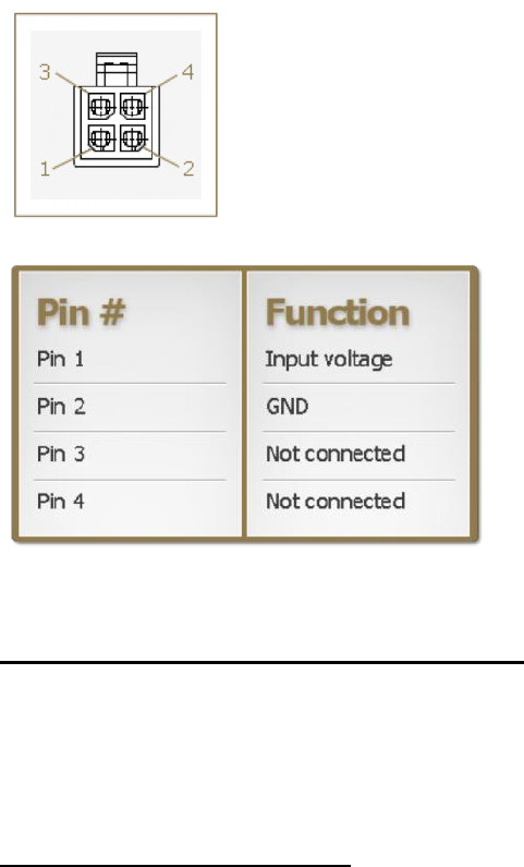
Modemulator User Guide
Page 72 of 120
Pinout
Radio Technology & Frequency Bands
3G UMTS/HSDPA/HSUPA/HSPA+: 800- 850/900/1900/2100 MHz and AWS band (1700/2100MHz)
(B1, B2, B4, B5, B6, B8)
2G GSM/GPRS/EDGE: 850/900/1800/1900 MHz
CDMA 1xRTT/EV-DO rev0/EV-DO revA (USR3520 only): 800/1900MHz (BC0, BC1)
Max. connectivity speeds
HSPA+: 14.4Mbps (Cat 10) down, 5.76 (Cat 6) up
EV-DO RevA mode: 3.1Mbps FL / 1.8Mbps RL
HSPA+ Rel 7 SW features CPC (DTX/DRX), Enhanced L2, EF-DPCH

Modemulator User Guide
Page 73 of 120
GPS
• Assisted/Standalone GPS
o Standalone GPS, Assisted GPS, gps OneXTRA™
o Wideband GPS processing (20MHz) for improved measurement accuracy
• Embedded Standalone GPS
o Tracking sensitivity: -159 dBm
o Cold start sensitivity: -145 dBm
o Hot start sensitivity: -159 dBm
o Open sky TTFF: cold start: 40 seconds
o Open sky TTFF: super hot start: 1 second
o Open sky accuracy: < 3M CEP -50
• NMEA sentences: GGA, GSA, GSV, RMC, VTG
Security
• Modemulator
o Connects over a secure private network
o Support for 1 Administrator account and 9 User accounts
o Caller ID Screening
o Password Prompting
o Dialback Security
o Configurable security warning banner (up to 256 characters)
o Configurable login banner (up to 64 characters)
• IPsec VPN
o Encryption: 3DES, AES128, AES 256
o Authentication: MD5, SHA1, SHA256
o Key Group: DH1, DH2, DH5, DH14
• Firewall
o DMZ
o Inbound Port Forwarding
o Outbound Port Filtering
o Outbound Trusted IPs
Minimum System Requirements
• Cellular device-to-device routing (for peer-to-peer operation)
• Computer hardware/software:
o Ethernet port/web browser (for Gateway set-up)
o RS-232 DTE port/terminal software (for Modemulator set-up)
• Optional peripheral hardware: RS-232 serial analog modem with access to PTSN
Command-line Interface
• Compatible with common Hayes modem AT commands

Modemulator User Guide
Page 74 of 120
Graphical User Interface
• HTML configuration is supported by most web browsers
Environmental
• Operating temperature: -30°C to 70°C
• Storage temperature: -40°C to 85°C
• Humidity operational: 5% - 95% non-condensing
• Operating altitude: up to 2000m
Enclosure Type
• Industrial Grade Aluminum
Mounting
• 6 through holes for M4 bolts - 2 x 2 compatible with VESA Mount MIS-D 75 (optional standard DIN
rail mounting interface)
Package Dimensions/Weight
• 8.5 x 5.55 x 2.5 in. (21.6 x 14.1 x 6.35 cm)
• 1.38 lb ( .63 kg)
Product Dimensions/Weight
• 4.53 x 4.13 x 1.77 in. (11.5 x 10.5 x 4.5 cm)
• 0.77 lb ( 0.35 kg)

Modemulator User Guide
Page 75 of 120
Troubleshooting and FAQs
General
If you have trouble with the USR3520/USR803520 first try the following:
Try cycling the power off and on, then repeat the setup process.
Make sure the correct COM port was selected.
Consult the cellular service provider to verify that the Modemulator base unit is setup properly.
Make sure the power supply is plugged in to an operational power outlet, and that the power
supply is also securely plugged into the unit.
Verify all cables and adaptors are correct for the type of ports.
Verify that the Modemulator card is fully seated in the base unit.
When power and interface cables are connected, type AT<Enter> to see if OK appears on the
terminal.
What are displayable characters?
"Displayable characters" are all ASCII characters from 20h thru 7Eh.
What are programmable characters?
All 3 of the programmable characters (Escape, Xon, Xoff) can be any ASCII character 00h thru 7Fh (0 thru
255 decimal).
What are dial modifier characters?
Dial modifier characters are any non-numeric displayable character following a dial (D) command.
Examples of common dial modifier characters used in dial-up modems are:
P T , ; " W @ / R ! L S $
Also punctuation characters like - ) ( and <space> are dial modifier characters.
Dial modifier characters (except comma, colon, and L) in Modemulator dial commands that initiate cellular
connections are ignored. Dial modifier characters in Modemulator dial commands that are forwarded to an
attached dial-up modem are processed by the dial-up modem.
Can I use the SIM from my phone for Modemulator?
Generally no. The SIM from your phone is not provisioned for peer-to-peer data connectivity, which
Modemulators require in order to emulate the analog PSTN and dial-up modems.
However, depending on how your SIM is provisioned, it may allow connectivity to the Internet, and
Modemulator can use this type of connectivity when operating in single-ended mode to originate a
connection to the IP address of a TCP/IP server.

Modemulator User Guide
Page 76 of 120
What type of screwdriver do I need for installing a SIM or an expansion card?
The gateway base unit panels are fastened by Torx T6 screws, so a Torx T6 screwdriver is required to
remove a panel. Torx is the tip style, and is also called “star” or “6-point”. T6 is the tip size.
What is peer-to-peer?
Peer-to-peer is a communications model in which each party has the same capabilities and either party
can initiate a communication session. Peer-to-peer devices are capable of originating or answering a
connection. Dial-up modems are an example of a peer-to-peer device.
What is point-to-point?
Point-to-point is a type of communications connection in which one device has an exclusive connection
with one other device. The Public Switched Telephone Network (PSTN) is an example of a point-to-point
network. An RS-232 serial link is another example.
Can I enable both Caller ID Screening and Password Prompting?
Yes. With Caller ID Screening and Password Prompting both enabled, a Modemulator connection will first
validate the originating Modemulator with Caller ID Screening, then prompt for a password. If either
authentication fails the connection will not complete.
Can I enable both Caller ID Screening and Dialback Security?
Yes. With Caller ID Screening and Dialback Security both enabled, a Modemulator connection will first
validate the originating Modemulator with Caller ID Screening, then prompt for a dialback number. If
either authentication fails the connection will not complete. When it does complete successfully, it will only
connect to an IP address listed in the Answerer’s phone directory.
Why does an originating Modemulator report BUSY?
Cellular data networks are packet-switched networks, and packets can be significantly delayed when
travelling large distances from one Modemulator to another. One reason an originating Modemulator can
report BUSY is when the total network delay exceeds the Modemulator busy timeout. Increasing the
originating Modemulator’s S7 setting may help by increasing the busy timeout.
Can I connect to the IP address reported by the USR3520/USR803520?
When the cellular service is provided by a Mobile Network Operator (MNO), the IP address reported by the
USR3520/USR803520 GUI or I7 screen may be public and routable. Normally this IP address provided by

Modemulator User Guide
Page 77 of 120
the MNO will be dynamic so it will change periodically, and the MNO may block access to this IP address
with a firewall.
When the cellular service is provided by a Mobile Virtual Network Operator (MVNO), the IP address
reported by the USR3520/USR803520 GUI or I7 screen is not public and routable. The reported IP address
is used only by the MVNO to route traffic to the USR3520/USR803520 on the cellular operator’s network.
The MVNO will translate the IP address using Network Address Translation (NAT) and provide you with a
different routable IP address, but the USR3520/USR803520 cannot report that IP address. The MVNO will
control whether your IP address is private or public, and static or dynamic.
How do I configure a Modemulator for connection to the Vodafone UMTS
network?
1. The Vodafone network requires any cellular device to report a Username and Password in order for the
cellular connection to complete. The Username and Password are not assigned by Vodafone or by an
MVNO, so an arbitrary Username and Password can be chosen by the User. Consult the
USR3520/USR803520 Gateway User Guide for instructions on entering a Username and Password.
2. Follow the instructions in the USR3520/USR803520 Gateway User Guide for selecting the “Generic
UMTS” network setting in the embedded GUI.
3. Enter the APN given by your cellular service provider. Consult the USR3520/USR803520 Gateway User
Guide for instructions on entering an APN.
4. The embedded GUI of the USR3520/USR803520 has a “Connect while on international roaming”
feature. Depending on how the Vodafone SIM is provisioned and on the geographical location of the
gateway, you may need to enable this setting.
The SIM is programmed with a Mobile Network Code (MNC) and a Mobile Country Code (MCC).
When a cellular device is connecting to a cellular network, the device receives the network’s MNC
and MCC which it compares to the MNC and MCC programmed in the SIM. If the SIM MNC doesn’t
match the network MNC, a roaming connection is established if the cellular service allows roaming
to that local cellular network. If also the SIM MCC doesn’t match the network MCC, the connection
is international roaming. Contact your cellular service provider to determine your SIM’s home
country, and whether roaming to your local cellular network is allowed.
How do I restore the Modemulator expansion card to factory settings?
To restore the Modemulator operating parameters in the i4 screen to factory values and make the factory
values non-volatile, enter this command string:
AT&F1&W <enter>
Modemulator User Guide
Page 78 of 120
To restore all other Modemulator configurations to factory default, enter the commands below as needed.
There is no need to restore configurations that are already at factory default.
Erase security banner:
AT{B <enter> <enter>
Restore factory login banner:
AT{L <enter> "USRobotics Courier M2M Modemulator Expansion Card" <enter>
Erase caller ID string:
AT{I= <enter>
Delete all passwords:
AT{S0= <enter>
AT{S1= <enter>
AT{S2= <enter>
AT{S3= <enter>
AT{S4= <enter>
AT{S5= <enter>
AT{S6= <enter>
AT{S7= <enter>
AT{S8= <enter>
AT{S9= <enter>
Disable all Administrator privileges:
AT{P1= <enter>
AT{P2= <enter>
AT{P3= <enter>
AT{P4= <enter>
AT{P5= <enter>
AT{P6= <enter>
AT{P7= <enter>
AT{P8= <enter>
AT{P9= <enter>
Erase all dialing directory entries:
AT{W <enter> y <enter>
Restore default Listener port:
AT{Z=8888 <enter>
Erase programmable CONNECT message:
AT{K= <enter>
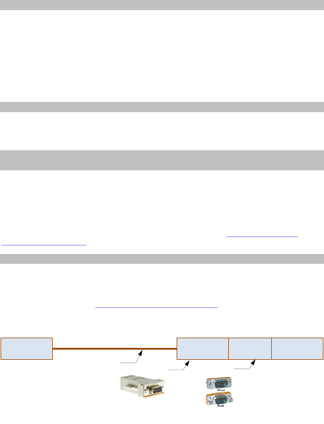
Modemulator User Guide
Page 79 of 120
Why do I need an M2M data plan with the Modemulator?
The Modemulator emulates the behavior of an analog modem, but actually connects over a cellular
network instead of the legacy Public Switched Telephone Network (PSTN). Any device that connects to a
cellular network must subscribe to a cellular service plan.
Also, since the Modemulator is sending and receiving digital data (not voice), the cellular service must be
a data plan (not a voice plan).
And in order to emulate the operation of the legacy PSTN, the cellular data plan must be provisioned for
peer-to-peer connectivity and static IP addressing. These provisioning features are available only from an
M2M cellular data plan (not from consumer cellular data plans).
Can the Modemulator connect simultaneously to several remote sites?
No, the Modemulator emulates the behavior of dial-up modems and the PSTN, which allows only point-to-
point connections from one endpoint to one other endpoint. A Modemulator must disconnect before a
connection to another site can be made.
Can I use the Modemulator to connect to an analog site over the cellular
network?
No. A dial-up modem sends and receives analog signals that can connect only to another analog modem.
Modern cellular networks don’t contain analog modems and don’t offer analog services. The voice services
that cell phones use are actually sending and receiving digital voice, not analog.
And also, cellular modem and gateways make data connections, not digital voice connections. The cellular
network’s digital voice service is too low-fidelity to carry a dial-up modem’s analog signal.
For an overview of cellular networking and the legacy PSTN, download the Cellular to Cellular Data
Communications whitepaper.
Can the Modemulator be connected to the console port of a Cisco router?
Yes, with the proper cable and adaptors, and with the proper settings, the Modemulator can connect to a
Cisco console port.
The Cisco console port is a serial port which can connect to the Modemulator’s Terminal port. It may be
useful to consult Cisco’s online Cabling Guide for Console and AUX Ports.
For example, if the Cisco console port is presented on an RJ45 connector, one way to make the connection
is as follows:
Standard Ethernet cable
(not rollover)
Cisco Terminal adaptor
Gender changer
(not null)
USR Modemulator
DB9F Terminal
port
Cisco RJ45
Console port
RJ45 to DB9F
DB9M to DB9M
Cisco DB9F-to-RJ45
TERMINAL Adaptor
DB9M/DB9M
Gender Changer (Coupler)

Modemulator User Guide
Page 80 of 120
Also, the Cisco console port will require the Modemulator to be pre-configured with certain settings. For
example, if the Cisco console port requires the Modemulator to be pre-configured for 9600bps 8-N-1 serial
format:
1. Connect a computer’s serial port to the Modemulator’s Terminal port with a serial cable and set the
computer’s serial parameters for 9600bps 8-N-1.
2. Enter any AT command to establish the 9600bps 8-N-1 serial settings in the Modemulator.
3. Use the &W command to save those serial setting into the Modemulator’s non-volatile memory.
The Cisco console port may work best with the Modemulator (or any modem) pre-configured for DTR
override, flow control off, quiet mode, command echo off, and autoanswer on. It may be useful to consult
Cisco’s online guide for Attaching a USRobotics Modem to the Console Port of a Cisco Router to see their
recommendations for configuring a USRobotics analog modem, and apply those recommendations to the
Modemulator as needed.
Contact USRobotics technical support if these troubleshooting tips did not solve your issue.
Modemulator User Guide
Page 81 of 120
Glossary of Terms
APN Access Point Name
ASCII American Standard Code for Information Interchange
CD Same as DCD, Data Carrier Detect
CID Caller ID
CRLF Carriage Return/Line Feed control character pair
CTS Clear To Send, used for H/W TXD flow control
DCD Data Carrier Detect
DCE Data Communication Equipment, such as a modem
DSR Data Set Ready (sometimes known as Modem Ready)
DTE Data Terminal Equipment, such as a computer
DTR Data Terminal Ready
ECIO Ratio (dB) of rcvd energy per code bit to interference level
EEPROM Electrically Erasable Programmable Read Only Memory
F/W Firmware
GUI Graphical User Interface
H/W Hardware
IMEI International Mobile-station Equipment Identity
IMSI International Mobile Subscriber Identity
IP Internet Protocol
MEID Mobile Equipment IDentifier
MVNO Mobile Virtual Network Operator
NVRAM Non-Volatile Random Access Memory
PSTN Public Switched Telephone Network
RAM Random Access Memory
RI Ring Indicate
RTS Request To Send, used for H/W RXD flow control
RX Receive
RXD Receive Data
S/W Software
TCP Transmission Control Protocol
TX Transmit
TXD Transmit Data
UTC Universal Time, Coordinated
WWAN Wireless Wide Area Network

Modemulator User Guide
Page 82 of 120
Support
1. Be prepared to provide model and serial numbers.
Product
Model Number
Courier Modemulator & 3G M2M Cellular Gateway
3520
Upgraded Product
Model Number
USRobotics Courier M2M 3G Cellular Gateway
3510
USRobotics Courier Modemulator Expansion Card
3516-EMU
The USR3520 has two serial numbers, the base unit serial number and the Modemulator expansion
card serial number. A USR3510 that was upgraded to a USR3520 also has two serial numbers, the
base unit serial number and the Modemulator expansion card serial number.
The base unit serial number is on the side of the package, bottom of the unit, and is shown
on the Modemulator I7 screen on the line labeled Cellular S/N.
The Modemulator expansion card serial number is shown on the Modemulator I7 screen on
the line labeled Modemulator S/N. If the Modemulator is not responding to the I7 command,
remove power from the unit and uninstall the Modemulator expansion card to find the
Modemulator expansion card serial number on the expansion card label.
2. Visit the Support section of the USRobotics Web site at www.usr.com/support/3520
Many of the most common issues that users experience have been addressed in the FAQ and
Troubleshooting Web pages for the USR3520. The Support Web pages also contain information on
the latest firmware, application software, and documentation updates.
3. Submit a technical support question to the USRobotics Technical Support Department using an
online form:
Country
Webmail
United States & Canada
http://www.usr.com/emailsupport
Austria
www.usr.com/emailsupport/de
Belgium (Flemish)
www.usr.com/emailsupport/nl
Belgium (French)
www.usr.com/emailsupport/be
Czech Republic
www.usr.com/emailsupport/cz

Modemulator User Guide
Page 83 of 120
Country
Webmail
Denmark
www.usr.com/emailsupport/ea
Finland
www.usr.com/emailsupport/ea
France
www.usr.com/emailsupport/fr
Germany
www.usr.com/emailsupport/de
Greece
www.usr.com/emailsupport/gr
Hungary
www.usr.com/emailsupport/hu
Ireland
www.usr.com/emailsupport/uk
Italy
www.usr.com/emailsupport/it
Luxembourg
www.usr.com/emailsupport/be
Netherlands
www.usr.com/emailsupport/nl
Norway
www.usr.com/emailsupport/ea
Poland
www.usr.com/emailsupport/pl
Portugal
www.usr.com/emailsupport/pt
Russia
www.usr.com/emailsupport/ru
Spain
www.usr.com/emailsupport/es
Sweden
www.usr.com/emailsupport/se
Switzerland
www.usr.com/emailsupport/de
Turkey
www.usr.com/emailsupport/tk
United Kingdom
www.usr.com/emailsupport/uk
For additional current support contact information, go to: http://www.usr.com/en/international/

Modemulator User Guide
Page 84 of 120
Appendices
Appendix A: ASCII Chart
Dec
Hex
Char
Dec
Hex
Char
Dec
Hex
Char
Dec
Hex
Char
00
00
NUL
18
12
DC2
36
24
$
54
36
6
01
01
SOH
19
13
XOFF
37
25
%
55
37
7
02
02
STX
20
14
DC4
38
26
&
56
38
8
03
03
ETX
21
15
NAK
39
27
ë
57
39
9
04
04
EOT
22
16
SYN
40
28
(
58
3A
:
05
05
ENQ
23
17
ETB
41
29
)
59
3B
;
06
06
ACK
24
18
CAN
42
2A
*
60
3C
<
07
07
BEL
25
19
EM
43
2B
+
61
3D
=
08
08
BS
26
1A
SUB
44
2C
'
62
3E
>
09
09
HT
27
1B
ESC
45
2D
-
63
3F
?
10
0A
LF
28
1C
FS
46
2E
.
64
40
@
11
0B
VT
29
1D
GS
47
2F
/
65
41
A
12
0C
FF
30
1E
RS
48
30
0
66
42
B
13
0D
CR
31
1F
US
49
31
1
67
43
C
14
0E
SO
32
20
SP
50
32
2
68
44
D
15
0F
SI
33
21
!
51
33
3
69
45
E
16
10
DLE
34
22
52
34
4
70
46
F
17
11
XON
35
23
#
53
35
5
71
47
G

Modemulator User Guide
Page 85 of 120
Dec
Hex
Char
Dec
Hex
Char
Dec
Hex
Char
Dec
Hex
Char
72
48
H
86
56
V
100
64
d
114
72
r
73
49
I
87
57
W
101
65
e
115
73
s
74
4A
J
88
58
X
102
66
f
116
74
t
75
4B
K
89
59
Y
103
67
g
117
75
u
76
4C
L
90
5A
Z
104
68
h
118
76
v
77
4D
M
91
5B
[
105
69
i
119
77
w
78
4E
N
92
5C
\
106
6A
j
120
78
x
79
4F
O
93
5D
]
107
6B
k
121
79
y
80
50
P
94
5E
à
108
6C
l
122
7A
z
81
51
Q
95
5F
_
109
6D
m
123
7B
{
82
52
R
96
60
`
110
6E
n
124
7C
|
83
53
S
97
61
a
111
6F
o
125
7D
}
84
54
T
98
62
b
112
70
p
126
7E
~
85
55
U
99
63
c
113
71
q
127
7F
DEL
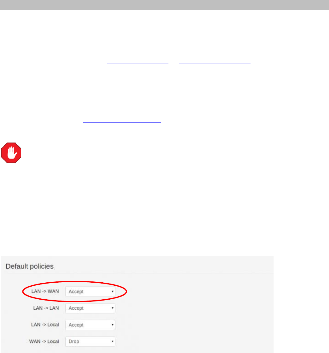
Modemulator User Guide
Page 86 of 120
Appendix B: Excessive Data Usage Warning
There are two default settings that can cause unintentional billable cellular data usage: LAN to WAN and
Auto Provisioning.
1. By default LAN to WAN routing is turned on. Once the gateway is connected to a cellular data network
it will route all of the attached computer’s Internet traffic through the cellular data network. To prevent
this cellular data usage, either turn off LAN to WAN or exit out of all programs that use the Internet
while configuring the gateway for its intended use. Otherwise, computer Internet traffic will continue to
use the LAN to WAN routing until the cellular gateway is disconnected.
2. By default auto provisioning is also turned on. This means that the gateway will connect to the USR
Universe and check for updates each time it is powered on. If an update is available the gateway will
automatically download and install the update. USR recommends auto provisioning only if the product
is properly registered on the USR Universe. If the product is not registered, or if the gateway has a low
cellular data rate plan, disable auto provisioning and check for updates manually to avoid the extra
data usage.
Do not manually or automatically update the gateway if a USR3510/USR803510 was
upgraded to a USR3520/USR803520. The update will remove the Modemulator upgrade.
How to disable LAN to WAN
Before installing a SIM card or setting-up the carrier information, connect a computer’s Ethernet port to
the gateway’s Ethernet port with a standard Ethernet cable, then open a web browser on the computer
and enter the address 192.168.1.1 into the address bar. Enter the default username (admin) and
password (admin). After a successful login, the Home screen will appear.
Click on the Firewall Tab.
Change the LAN -> WAN from Accept to Reject and click Save changes.
Now continue to configure the gateway as needed.
Modemulator User Guide
Page 87 of 120
If the application requires LAN to WAN routing, close any programs running on the attached
computer that might be using the Internet before returning to this page to re-enable LAN to WAN.
Closing Programs
If LAN to WAN routing is left enabled during the configuration process, USR strongly recommends closing
any programs that might be using the Internet (web browsers, instant messengers, email programs, etc.)
before connecting the gateway to a cellular network. Be sure to close any programs that are running in
the background; e.g. auto updates or anti-virus. There are applications available that provide a list of
current network activity like Windows’ Resource Monitor that can be used as a guideline.
Auto Provisioning
By default the gateway connects to the USR Universe each time the device is powered on, and checks for
an updated image file. The gateway will automatically download and install updates from the USR
Universe over the cellular connection. If the product is not properly registered on the USR Universe, or to
reduce cellular data usage, disable auto provisioning and manually check for updates. If auto provisioning
is turned off, USR strongly recommends checking for updates on a regular basis to manually update the
gateway when updates are available.
How to Disable Auto Provisioning
Before installing a SIM card or setting-up the carrier information, connect a computer’s Ethernet port to
the gateway’s Ethernet port with a standard Ethernet cable, then open a web browser on the computer
and enter the address 192.168.1.1 into the address bar. Enter the default username (admin) and
password (admin). After a successful login, the Home screen will appear.
Click on the Provisioning Tab.
To disable this feature go to Settings, then next to Enable automatic provisioning click No and click Save
Changes.

Modemulator User Guide
Page 88 of 120
Appendix C: DTE Interface Requirements
Baud rate and parity are automatically detected for each AT command.
Baud rate must be one of the following:
300, 1200, 2400, 4800, 9600, 19200, 38400, 57600, 115200
Parity must be one of the following:
8N1 - 8 data bits, no parity, 1 stop bit
7E1 - 7 data bits, even parity, 1 stop bit
7O1 - 7 data bits, odd parity, 1 stop bit
7M1 - 7 data bits, mark parity, 1 stop bit
7S1 - 7 data bits, space parity, 1 stop bit
7M1 is the same as 7 data bits, no parity, 2 stop bits

Modemulator User Guide
Page 89 of 120
Appendix D: Result Codes
0/OK Command has executed
1/CONNECT Successfully connected with another Modemulator
2/RING Incoming RING detected from remote Modemulator
3/NO CARRIER Data connection has terminated
4/ERROR Command is invalid or DSR not asserted
6/NO DIAL TONE Network TCP connection attempt timed out
7/BUSY Cellular: half of S7 expired with no ringbacks
8/NO ANSWER Ringback(s) detected, but S7 expired
10/REFUSED Caller ID failed authentication
11/RINGING Remote Modemulator is displaying RING

Modemulator User Guide
Page 90 of 120
Appendix E: ATI6 Disconnect Reasons
1. None
No connection has been made since reset, or in Remote Command Mode while still connected.
2. DTR dropped
DTR was de-asserted by the local DTE on the RS-232 interface.
3. Escape Code
Escape Code (default='+++') was issued by the local DTE.
4. Loss of Carrier
Gateway or analog modem de-asserted DCD.
5. Inactivity Timeout
Local or remote Modemulator disconnected due to data inactivity.
6. DISC Received
Remote Modemulator disconnected (unspecified reason).
7. Link Timeout
Local Modemulator disconnected due to network latency.
8. Keypress Abort
A key was pressed during connection handshake.
9. Refused
Caller ID failed authentication at the Listener end.

Modemulator User Guide
Page 91 of 120
Appendix F: Flow Control
1. Hardware Flow Control
H/W Transmit Flow Control
When the Modemulator's incoming transmit data buffer is getting full, it will de-assert the Clear to
Send (CTS) signal on the RS-232 interface, which commands the local DTE to stop sending
transmit data to the Modemulator. When sufficient space becomes available, CTS will be re-
asserted, enabling data flow.
H/W Receive Flow Control
If set to &R2, the Modemulator will obey the incoming Request to Send (RTS) signal, sending or
stopping receive data to the local DTE.
2. Software Flow Control
S/W Transmit Flow Control
When the Modemulator's incoming transmit data buffer is getting full, it will send the
programmable Xoff character to the local DTE, which commands the DTE to stop sending transmit
data to the Modemulator. When sufficient space becomes available, the programmable Xon
character will be sent, enabling data flow.
S/W Receive Flow Control
If set to &I1 or &I2, the Modemulator will obey the incoming Xon/Xoff flow control characters,
sending or stopping receive data to the local DTE. &I1 will pass Xon/Xoff through to the remote
Modemulator, while &I2 will not.
S/W flow control should not be used for binary file transfers, since Xon and Xoff characters in the
data could be falsely interpreted as flow control.

Modemulator User Guide
Page 92 of 120
Appendix G: Dial Security
This appendix contains information about:
Setting up Caller ID Screening
Setting up Password Prompting
Granting Administrator Privileges To A User
Setting up Dialback Security
Overview
Dial Security is designed to protect networks and data centers from unauthorized access. There are three
forms of Dial Security; each will be explained later in this appendix:
Caller ID Screening
Password Prompting
Dialback Security
You should be familiar with these terms before you continue:
Remote site: One of multiple locations where a Modemulator is attached to equipment that transfers data
to or from a host site.
Host site: The single location where a Modemulator is attached to a terminal or application server that
transfers data to or from multiple remote sites.
Remote Modemulator: A Modemulator attached to equipment at a remote site. In a peer-to-peer system
a remote Modemulator may originate or answer a connection.
Host Modemulator: A Modemulator attached to a terminal or application server at a host site. In a peer-
to-peer system a host Modemulator may originate or answer a connection.
Administrator: With Password Prompting enabled in an answering Modemulator, an Administrator is a
person or application that has privileges to contact the answering Modemulator to remotely configure it or
to transfer data to/from the equipment attached to its Terminal port.
With Password Prompting disabled, any person or application has privileges to contact and remotely
configure the answering Modemulator, and to transfer data to/from the equipment attached to its
Terminal port.
User: With Password Prompting enabled in an answering Modemulator, a User is a person or application
that has no privileges to remotely configure the answering Modemulator, but is allowed to contact the
answering Modemulator and transfer data to/from the equipment attached to its Terminal port.
Any User can be granted Administrator privileges by the default Administrator or any other User that has
Administrator privileges.

Modemulator User Guide
Page 93 of 120
Setting Up Caller ID Screening
An originating Modemulator has the option of sending a Caller ID (CID) number during the connection
handshake.
If the answering Modemulator has CID enabled, it will compare the received CID number with the phone
numbers stored in its dialing directory. If the CID number is not found, the connection will fail and the
originating Modemulator will display REFUSED.
Caller ID cannot be used when the answering Modemulator is operating in single-ended mode.
In the case of Modemulators replacing legacy dial-up modems, it is recommended that each
originating Modemulator CID number be programmed with its former PSTN phone number. Each
answering Modemulator should have an entry in its dialing directory containing the originator’s
phone number.
The User can, however, select any numeric string (up to 23 digits) as a Caller ID number, as long
as the answering Modemulator has a corresponding entry in its dialing directory.
The originating and answering Modemulator must both be configured to enable Caller ID, which can be
done locally (pre-deployment) or remotely (post-deployment). The following steps will describe how to do
local configuration. To do remote configuration, see Appendix H for details about using Remote Access.
Here are the steps for locally setting up Caller ID Screening:
1. Enter a CID number in the originating Modemulator
Connect a computer serial port to the originating Modemulator Terminal port with a serial cable.
Run a terminal application on the computer to facilitate sending commands into the Modemulator.
Use the {I command to enter the Caller ID number that will be sent to the Listener during
Modemulator handshake protocol. The CID number may be up to 23 numeric (0-9) digits.
Attempting to enter a non-numeric character or more than 23 digits will return ERROR.
Example:
AT{I=18005551234
The number written by the {I command is automatically stored to EEPROM. It does not require
you to send &W.
2. Enable CID in the originating Modemulator
Issue the {C1 command to enable CID in the originating Modemulator.
Example:
AT{C1&W

Modemulator User Guide
Page 94 of 120
The {C setting is not automatically written to EEPROM. Send &W to maintain the S registers after
a reset.
3. Enter the CID number of the originating Modemulator into the answering Modemulator’s dialing
directory
Connect a computer serial port to the answering Modemulator Terminal port with a serial cable.
Run a terminal application on the computer to facilitate sending commands into the Modemulator.
Use the {Y command to enter the same CID number that was programmed into the originating
Modemulator in step 1, along with the port number and IP address of the originating Modemulator.
Example:
AT{Y=18005551234:8888:172.18.3.2
The number written by the {Y command is automatically stored to EEPROM. It does not require
you to send &W.
4. Enable CID in the answering Modemulator
Issue the {C1 command to enable CID in the answering Modemulator.
Example:
AT{C1&W
The {C setting is not automatically written to EEPROM. Send &W to maintain the S registers after
a reset.
5. Caller ID Screening is now operational
Steps 1 and 2 configure the originating Modemulator to always send its CID number when originating a
connection. Steps 3 and 4 configure the answering Modemulator to always require a valid CID number
when answering a connection. If a valid CID number is not received during a connection handshake, the
connection will fail and the originating Modemulator will display REFUSED.
In a peer-to-peer system any Modemulator can originate or answer a connection. In that case, it
is recommended to set up each Modemulator as both CID originator and CID answerer.
To disable CID, issue the {C0 command in the answering Modemulator.
Example:
AT{C0&W

Modemulator User Guide
Page 95 of 120
Setting Up Password Prompting
With Password Prompting enabled in an answering Modemulator, an originating Modemulator will present
a login banner and a login prompt before completing a connection. An optional security banner may
precede the login banner. In order to complete the connection, a valid password must be entered at the
login prompt.
If an invalid password is entered, the connection will fail and the originating Modemulator will display
Login Failed. Or if no password is entered before S64 times-out, the connection will fail and the originating
Modemulator will display Login Failed.
The Modemulator can store up to ten security accounts: one default Administrator account and nine User
accounts. The account profiles are stored in the answering Modemulator’s NVRAM.
The answering Modemulator must be configured to enable Password Prompting, which can be done locally
(pre-deployment) or remotely (post-deployment). The following steps will describe how to do local
configuration. To do remote configuration, see Appendix H for details about using Remote Access.
Here are the steps for locally setting up Password Prompting:
1. Enter an Administrator password in the answering Modemulator to enable Password Prompting
Connect a computer serial port to the answering Modemulator Terminal port with a serial cable.
Run a terminal application on the computer to facilitate sending commands into the Modemulator.
In order to enable Password Prompting, a password must be programmed for the default
Administrator (User 0). Use the {S command to enter an Administrator password. The password
may contain up to 15 displayable characters (case sensitive) with no spaces.
Do not forget the Administrator password! If the Administrator password is forgotten,
the only way to reset the password is via a terminal connected locally to the
Modemulator’s Terminal port.
Example:
AT{S0=p
(where p is replaced with the desired password)
The passwords written by the {S command are automatically stored to EEPROM. It does not
require you to send &W.
2. Enter a User password (optional)
Connect a computer serial port to the answering Modemulator Terminal port with a serial cable.
Run a terminal application on the computer to facilitate sending commands into the Modemulator.
Use the {S command to enter a User password.

Modemulator User Guide
Page 96 of 120
Example:
AT{Sn=p
(where n is any User number from 1 through 9, and p is replaced with the desired password)
The passwords written by the {S command are automatically stored to EEPROM. It does not
require you to send &W.
3. Enable Auto-answer in the answering Modemulator and save to NVRAM
Set register S0 greater than 0 to enable Auto-answer in the answering Modemulator.
Example:
ATS0=1&W
S register settings are not automatically written to EEPROM. Send &W to maintain the S registers
after a reset.
4. Password Prompting is now operational
In order to disable Password Prompting, use the {S command to delete the Administrator (User 0)
password.
Example:
AT{S0=
(Issuing the command with a blank password deletes the previous password)
Granting Administrator Privileges to a User
When Password Prompting is enabled, Users 1-9 have no Administrator privileges by default, but can be
individually granted Administrator privileges.
A User can be granted or denied Administrator privileges locally (pre-deployment) or remotely (post-
deployment). The following steps will describe how to do local configuration. To do remote configuration,
see Appendix H for details about using Remote Access.
To grant Administrator privileges to a User:
Connect a computer serial port to the originating Modemulator Terminal port with a serial cable. Run a
terminal application on the computer to facilitate sending commands into the Modemulator.
Use the {Pn=x command to grant (x=1) or deny (x=0) Administrator privileges to any User (n).

Modemulator User Guide
Page 97 of 120
Example:
AT{P2=1
(to grant Administrator privileges to User 2)
The Administrator privilege status written by the {P command is automatically stored to EEPROM.
It does not require you to send &W.
Setting Up Dialback Security
With Password Prompting and Dialback Security both enabled in an answering Modemulator, an originating
Modemulator will present a login banner and a dialback prompt before completing a connection. An
optional security banner may precede the login banner. In order to complete the connection, the valid
phone number of the originating Modemulator must be entered at the dialback prompt. The answering
Modemulator can store up to 7200 phone numbers in its dialing directory, and any of the numbers in the
dialing directory can be valid dialback phone numbers (a.k.a. whitelist).
If the valid phone number of the originating Modemulator is entered before S64 times-out, the
answering Modemulator will disconnect and after the duration set by the S44 register it will
attempt to dialback the originating Modemulator.
If an invalid phone number (not found in the answering Modemulator’s dialing directory) is entered
before S64 times-out, the connection will fail and the originating Modemulator will display Login
Failed.
If nothing is entered before S64 times-out, the connection will fail and the originating Modemulator
will display Login Failed.
If a valid phone number of another Modemulator is entered, the answering Modemulator will
disconnect and after the duration set by the S44 register it will attempt to dial that Modemulator.
Dialback Security must be enabled in the answering Modemulator, which can be done locally (pre-
deployment) or remotely (post-deployment). The following steps will describe how to do local
configuration. To do remote configuration, see Appendix H for details about using Remote Access.
Here are the steps for locally setting up Dialback Security:
1. Password Prompting must be enabled in the answering Modemulator for Dialback Security to operate.
Follow the instructions in Setting Up Password Prompting before proceeding to the next step.
2. Enter the dialback phone number of the originating Modemulator into the answering Modemulator’s
dialing directory.
Connect a computer serial port to the answering Modemulator Terminal port with a serial cable.
Run a terminal application on the computer to facilitate sending commands into the Modemulator.
Use the {Y command to enter the dialback phone number of the originating Modemulator into the
answering Modemulator’s dialing directory.

Modemulator User Guide
Page 98 of 120
Example:
AT{Y=5556789:8888:172.18.3.3 <Enter>
In this example 5556789 is the phone number chosen for the originating Modemulator, 172.18.3.3
is the IP address of the originating Modemulator, and 8888 is the listening port of the originating
Modemulator.
The number written by the {Y command is automatically stored to EEPROM. It does not require
you to send &W.
3. Enable Auto-answer in the answering Modemulator and save to NVRAM
Set register S0 greater than 0 to enable Auto-answer in the answering Modemulator.
Example:
ATS0=1&W
4. Enable Dialback Security in the answering Modemulator and save to NVRAM
Issue the {D1 command to enable Dialback Security in the answering Modemulator.
Example:
AT{D1&W
Steps 3 and 4 can be performed with the single compound command ATS0=1{D1&W.
5. Enable Auto-answer in the originating Modemulator and save to NVRAM
Connect a computer serial port to the originating Modemulator Terminal port with a serial cable.
Run a terminal application on the computer to facilitate sending commands into the Modemulator.
Set register S0 greater than 0 to enable Auto-answer in the originating Modemulator.
Example:
ATS0=1&W
S register settings are not automatically written to EEPROM. Send &W to maintain the S registers
after a reset.
6. Dialback Security is now operational
phone
number
port
number
IP
address


Modemulator User Guide
Page 100 of 120
Appendix H: Remotely Accessing and Configuring the Modemulator
This appendix contains information about:
Setting Up For Remote Access
Starting A Remote Access Session
Ending A Remote Access Session
Overview
Remote Modemulators can be accessed and configured over the cellular network via a host Modemulator.
Privileges to do Remote Access depend on whether Password Prompting is enabled or disabled.
With Password Prompting disabled, any User can do Remote Access
With Password Prompting enabled, the Administrator or any User with Administrator privileges can
do Remote Access
You should be familiar with these terms before you continue:
Remote site: One of multiple locations where a Modemulator is attached to equipment that transfers data
to or from a host site.
Host site: The single location where a Modemulator is attached to a terminal or application server that
transfers data to or from multiple remote sites.
Remote Modemulator: A Modemulator attached to equipment at a remote site. In a peer-to-peer system
a remote Modemulator may originate or answer a connection.
Host Modemulator: A Modemulator attached to a terminal or application server at a host site. In a peer-
to-peer system a host Modemulator may originate or answer a connection.
Administrator: With Password Prompting enabled in an answering Modemulator, an Administrator is a
person or application that has privileges to contact the answering Modemulator to remotely configure it or
to transfer data to/from the equipment attached to its Terminal port.
With Password Prompting disabled, any person or application has privileges to contact and remotely
configure the answering Modemulator, and to transfer data to/from the equipment attached to its
Terminal port.
User: With Password Prompting enabled in an answering Modemulator, a User is a person or application
that has no privileges to remotely configure the answering Modemulator, but is allowed to contact the
answering Modemulator and transfer data to/from the equipment attached to its Terminal port.
Any User can be granted Administrator privileges by the default Administrator or any other User that has
Administrator privileges.

Modemulator User Guide
Page 101 of 120
Setting Up for Remote Access
Remote Access allows authorized Users to remotely issue AT commands from a Modemulator to another
Modemulator that is in Remote Command Mode. The AT commands that are supported by Remote
Command Mode are identified with a ‘*’ in the Command Reference chapter of this document.
Remote Command Mode is enabled on a per-connection basis at the originating Modemulator by issuing
the {R1 command to schedule Remote Command Mode for the next connection with an answering
Modemulator. The Remote Command Mode scheduling will automatically clear upon disconnect.
Here are the steps for locally setting up Remote Access:
1. Connect a computer serial port to the originating Modemulator Terminal port with a serial cable. Run a
terminal application on the computer to facilitate sending commands into the Modemulator.
2. Issue the {R1 command to schedule Remote Command Mode in the originating Modemulator.
Example:
AT{R1
To prevent Remote Command Mode from being enabled following every reset, USR recommends
not sending &W to the Modemulator while {R1 is set.
In Remote Command Mode, if S19=0, it will temporarily be set to 5 (5 minute Inactivity Timeout)
to prevent falsely staying connected if the TCP connection has been lost.
Starting A Remote Access Session
1. Dial the remote Modemulator that you want to manage. Use any form of the D command (ATD, ATD:
or ATDL) to initiate a connection to the remote Modemulator that you want to manage.
Example:
ATD18005551234
If the originating Modemulator detects that the phone number being dialed is a PSTN number and
if a dial-up modem is connected to the Modemulator “Modem” port, Modemulator will attempt a
dial-up connection. Regardless if that attempt succeeds or not, {R1 will automatically revert to
{R0.
Password Prompting Is Disabled
If Password Prompting is disabled in the answering Modemulator, the originating Modemulator will
display a CONNECT message and enter Remote Command mode. The answering Modemulator will then

Modemulator User Guide
Page 102 of 120
accept and process any AT commands identified with a ‘*’ in the Command Reference chapter of this
document.
Password Prompting Is Enabled
If Password Prompting is enabled in the answering Modemulator, the originating Modemulator will
display a CONNECT message, the login banner, and the login prompt.
2. Enter a password at the login prompt.
If the password is accepted and has Administrator privileges, a Logged In message is displayed and
the answering Modemulator enters Remote Command Mode. The answering Modemulator will then
accept and process any AT commands identified with a ‘*’ in the Command Reference chapter of
this document.
If the password is accepted but has no Administrator privileges, a No Admin Privileges message is
displayed and the answering Modemulator then completes the connection to the equipment
attached to its Terminal port.
If the password is not accepted, the answering Modemulator will disconnect, and the originating
Modemulator will display a Login Failed message and return to command mode.
If no password is entered before S64 times-out, the answering Modemulator will disconnect, and
the originating Modemulator will display a Login Failed message and return to command mode.
Ending A Remote Access Session
There are three ways to exit Remote Command Mode:
1. Use the O command to make the answering Modemulator exit Remote Command Mode and complete
the connection to the equipment attached to its Terminal port.
Example:
ATO
2. Use the H command to make the answering Modemulator exit Remote Command Mode and disconnect.
Example:
ATH
3. De-assert DTR on the terminal application to make the originating Modemulator disconnect. Then re-
assert DTR to allow further communication.
The Remote Command Mode scheduling bit will automatically clear upon disconnecting by any method,
disabling Remote Command Mode in subsequent connections

Modemulator User Guide
Page 103 of 120
Appendix I: Flashing New Firmware into Modemulator Card
Firmware can be flashed into a Modemulator expansion card locally (pre-deployment) or remotely (post-
deployment). The following steps will describe how to do local flashing. To do remote flashing, see
Appendix H for details about Remote Access.
To flash new firmware into a Modemulator card:
You will need a local computer with a serial port and terminal application, and access to the Internet.
1. Download the new Modemulator firmware hex file from the USR support website onto your computer.
2. Connect the computer serial port to the Modemulator Terminal port with a serial cable. Run a terminal
application on the computer to facilitate sending commands into the Modemulator.
You will need to know how to send a hex file using ASCII protocol (text file) from your terminal
application. Consult the terminal application documentation for help.
3. Use the !! command to begin the procedure of flashing new firmware into the Modemulator card's
processor.
Example:
AT!!
The following message will be displayed:
Flash New Code
Are you sure [Y/N]?

Modemulator User Guide
Page 104 of 120
4. Type Y to continue or N to abort the flash process.
After typing Y, the Boot> prompt will be displayed:
Press ! to abort the flash process, exit the boot loader, and restart the current flash image.
Step 5 erases the current Modemulator firmware image. However the system will
remain operational (with limited capability) until new firmware is loaded.
5. Within 40 seconds, type these three characters: #$%.
If the characters are not entered within 40 seconds, the flash process will abort and exit the boot
loader, restarting the current flash image.
(Press '!' to Reset)
Boot>

Modemulator User Guide
Page 105 of 120
After typing the three characters, the following will be displayed:
6. Within 40 seconds after LOAD HEX FILE appears, start sending the hex file using ASCII protocol (text
file or raw binary) from the terminal application. When the file transfer completes, a checksum will be
performed. If it is successful, Modemulator will be in AT command mode, with OK responses.
If the hex file is not sent within 40 seconds, or if the checksum fails, you will see Boot> instead of the
normal OK response after AT commands. Repeat from step 3. If flashing cannot succeed, the hex file
may be corrupt and should be replaced with a fresh file from USR's website or from customer service.
Please wait.......
LOAD HEX FILE
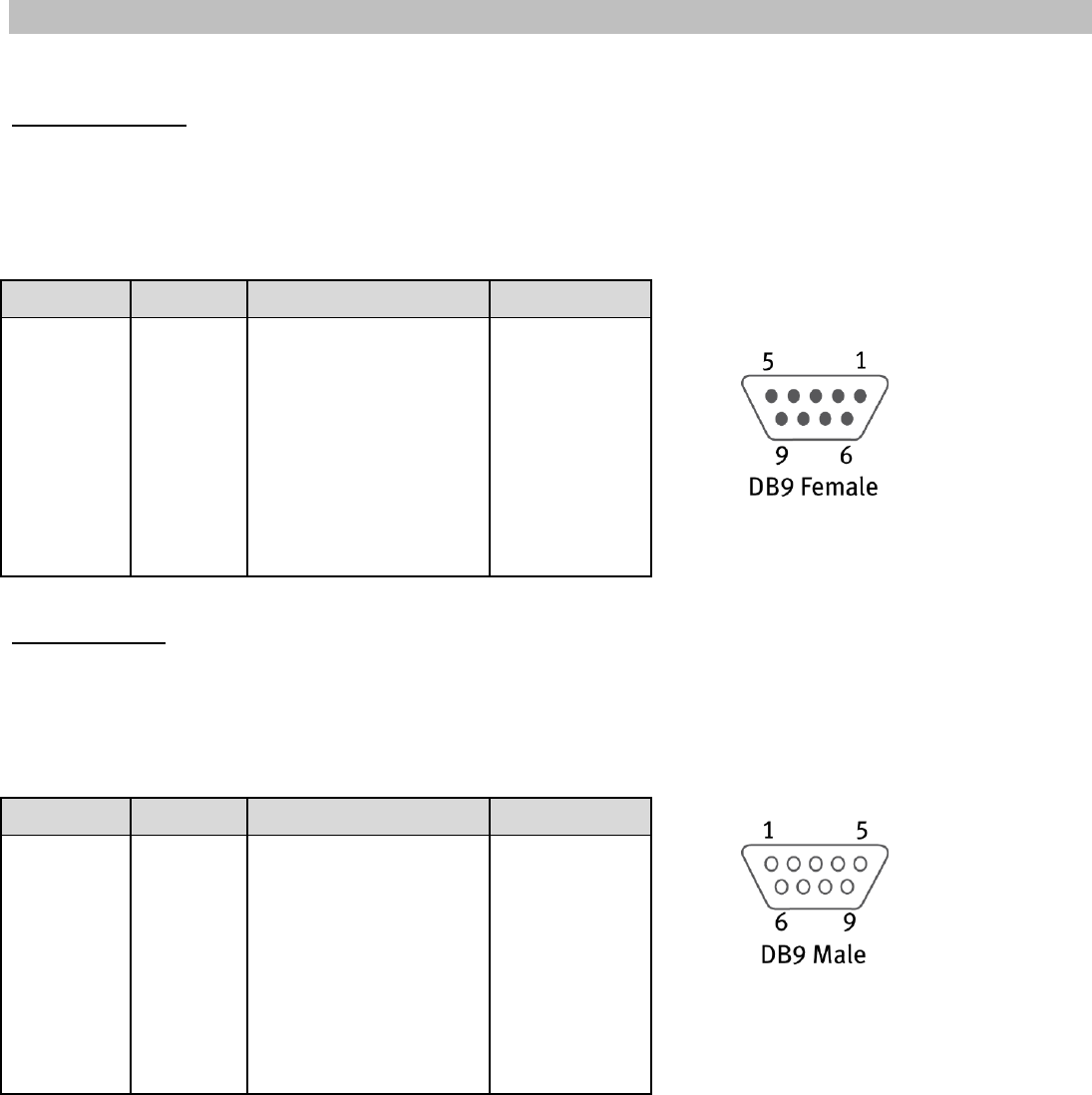
Modemulator User Guide
Page 106 of 120
Appendix J: DB9 Pinouts
The USR3520/USR803520 has two DB9 serial ports.
Terminal Port
The USR3520/803520 Terminal port is an RS-232 DCE presented on a DB9 female connector using a
standard pinout.
RS-232 output signal levels are nominally ±5v.
Modem Port
The USR3520/803520 Modem port is an RS-232 DTE presented on a DB9 male connector using a standard
pinout.
RS-232 output signal levels are nominally ±5v.
DB9F Pin
Symbol
Description
Direction
1
DCD
Carrier Detect
Output
2
TXD
Transmit Data
Output
3
RXD
Receive Data
Input
4
DTR
Data Terminal Ready
Input
5
GND
Ground
-
6
DSR
Data Set Ready
Output
7
CTS
Clear To Send
Input
8
RTS
Request To Send
Output
9
RI
Ring Indicator
Output
DB9M Pin
Symbol
Description
Direction
1
DCD
Carrier Detect
Input
2
RXD
Receive Data
Input
3
TXD
Transmit Data
Output
4
DTR
Data Terminal Ready
Output
5
GND
Ground
-
6
DSR
Data Set Ready
Input
7
RTS
Request To Send
Output
8
CTS
Clear To Send
Input
9
RI
Ring Indicator
Input
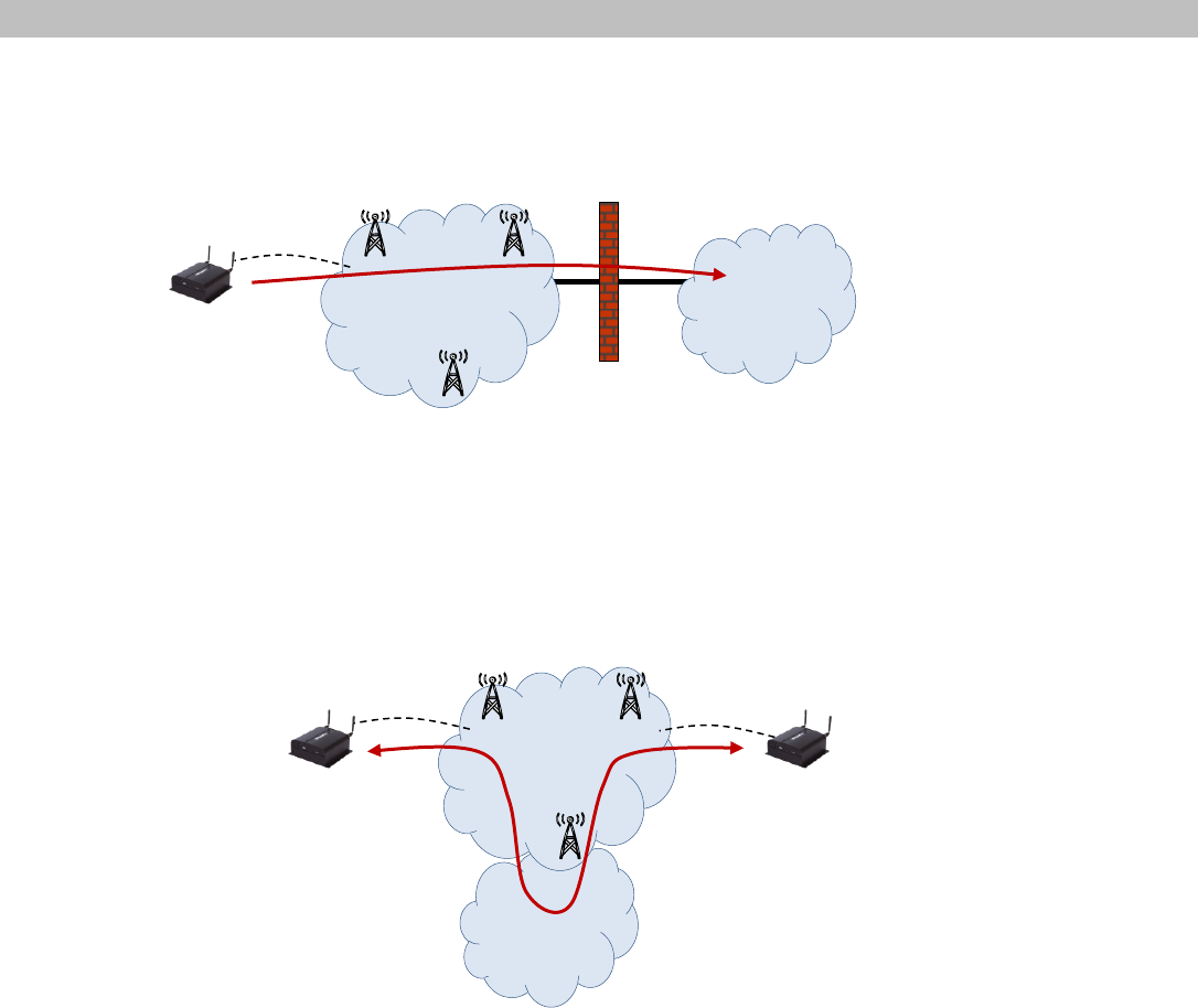
Modemulator User Guide
Page 107 of 120
Appendix K: Peer-To-Peer Cellular Data Service
Conventional cellular data service routes connections from a mobile device to the Internet, illustrated
below. The Modemulator can use this type of data service only when operating in single-ended mode to
make mobile-originated connections.
In order to emulate the PSTN, the Modemulator requires a special type of cellular data service when
operating in the default peer-to-peer mode that doesn’t route connections to or through the Internet. The
Modemulator requires service that allows connection from one mobile device to another mobile device.
This type of peer-to-peer data service is typically not available directly from mobile operators. However,
Mobile Virtual Network Operators (MVNOs) can provide this type of service, illustrated below.
With this type of peer-to-peer data routing, each of the mobile devices are assigned a private, static IP
address. An originating Modemulator can contact an answering Modemulator by addressing the IP address
of the answering Modemulator. The IP addresses are routable only within the MVNO private network, and
are not reachable by any outside networks.
When engaging with an MVNO to provide cellular data service for Modemulator, be sure to specify this
type of peer-to-peer data routing. Also be sure to ask the MVNO about any restrictions in connectivity
between devices or between different cellular networks.
Firewall
MVNO
Cellular
Data Network
Cellular
Data Network Internet

Modemulator User Guide
Page 108 of 120
Appendix L: Leased Line Operation
The &L1 command may be used to emulate the behavior of analog leased line modems. One Modemulator
must be designated as originator, while the other Modemulator must be the answerer (Listener). The
answerer must have autoanswer enabled (S0 greater than zero), and the originator must have S0 set to
zero.
The User should decide whether response codes will be displayed, and set the Q command appropriately.
Register S44 determines how many seconds after a disconnect that the originating Modemulator waits
before attempting to reconnect with the answering Modemulator.
When the &L1 command is issued to the originating Modemulator, it will attempt to connect with the
answering Modemulator using the last dialed number, similar to issuing ATDL. It is, therefore, necessary
to issue ATDn (where n is the desired phone number in the directory), or ATD:n (where n is the desired IP
address) one time to populate the Last Dialed Number area. This means that the &L1 command also
emulates the behavior of auto-redial.
If there is ever a disconnect, such as "DISC Received", "Loss of Carrier" or "Link Timeout", the originating
Modemulator will wait S44 (default=15) seconds, and attempt to reconnect, repeating indefinitely.
To disable leased line operation, enter the escape code (default is +++) or de-assert the RS-232 DTR
signal to the originating Modemulator to cause a disconnect, then enter the &L0 command before the
Modemulator attempts to reconnect.

Modemulator User Guide
Page 109 of 120
Appendix M: Break Sequence Operation
If the Modemulator is in a cellular connection, it detects a break signal (spacing data bits longer than one
character length) sent by the DTE into its Terminal port, and sends a token representing the break to the
remote Modemulator. The remote Modemulator receives the token and generates a break signal on the
DTE's RXD line. The length of the generated break signal is controlled by S21 (in 10 ms increments) on
the receiving Modemulator. Set S21=0 on the receiving Modemulator to disable generation of break
signals.
Since most of the data buffering takes place in the gateway's memory, the only version of break handling
supported is unexpedited, non-destructive (&Y3 in USRobotics Courier analog modems).

Modemulator User Guide
Page 110 of 120
Appendix N: Alternative Command Set
There are some dial-up modems that use an alternative command set. Most of the commands pertain to
purely analog modem functions, such as modulation speeds, speaker commands, etc., so are not
applicable.
A few of the alternative commands correspond to commands in the Modemulator's USR Courier-based
command set, as shown below:
USR
Alt
Description
&H0
&K0
Flow Ctrl Disabled
&H1
&K3
Flow Ctrl H/W
&H2
&K4
Flow Ctrl S/W
&I1
\X1
Xon/Xoff Signals Local & Remote
&I2
\X0
Xon/Xoff Signals Local Only
S19
S30
Inactivity Timeout (minutes)
S21
\Bn
Break Time
S21 in hundredths of seconds
\B in tenths of seconds
I4
&V
Display RAM Variables
S21
Displayed in &V screen
000
Displayed as \B0 in &V
001-015
Displayed as \B1 in &V
016-025
Displayed as \B2 in &V
026-035
Displayed as \B3 in &V
036-045
Displayed as \B4 in &V
046-055
Displayed as \B5 in &V
056-065
Displayed as \B6 in &V
066-075
Displayed as \B7 in &V
076-085
Displayed as \B8 in &V
086-255
Displayed as \B9 in &V

Modemulator User Guide
Page 111 of 120
If &I0 is issued, S/W Recv Flow Ctrl is displayed as Disabled in &V
Other examples:
Issuing &K3 results in a setting of &H1
Issuing \X0 results in a setting of &I2
Issuing S30=5 results in a setting of S19=5
Issuing \B3 results in a setting of S21=30
Issuing &V (with &F1 settings) displays the following:
The settings in the &V screen correspond to the equivalent settings in the I4 screen:
AT&V
----Option---------- -Setting- Cmd ----Option---------- -Setting- --Cmd--
Command Echo Enabled E1 Originate Only Disabled {O0
Online Echo Disabled F1 Remote Command Mode Disabled {R0
Result Codes Enabled Q0 Break Time 100 ms \B1
Result Form Verbal V1 S/W Recv Flow Ctrl Disabled
Dialtn,Busy,Ringing Enabled X7
/ARQ/V34/LAPM/V42BIS Enabled &A3 Answer Ring Number 000 S00=000
DCD Action Std RS232 &C1 Escape Character '+' S02=043
DTR Action Std RS232 &D2 No Answer Timeout 060 sec S07=060
Flow Control Hardware &K3 Comma Pause 002 sec S08=002
Line Type Normal &L0 Xon Character ^Q S22=017
H/W Recv Flow Ctrl RTS &R2 Xoff Character ^S S23=019
DSR Action Override &S0 DTR Validation Time 002 1/10 S25=002
Caller ID Disabled {C0 Inactivity Timeout 000 min S30=000
Dialback Security Disabled {D0 Leased Retry Timer 015 sec S44=015
Command Fwd to Modem Enabled {F0 Heartbeat Period 020 sec S60=020
High Speed CONN msg Disabled {H0 Max Latency 120 sec S61=120
Concatenate Banners Disabled {J0 Login Timeout 060 sec S64=060
Single-Ended Disabled {M0 Analog Answ Timeout 015 sec S65=015
OK

Modemulator User Guide
Page 112 of 120
ati4
USRobotics Courier EMU Settings...
BAUD=9600 PARITY=N WORDLEN=8
E1 F1 Q0 V1 X7
&A3 &C1 &D2 &H1 &I0 &L0 &R2 &S0
{C0 {D0 {F0 {H0 {J0 {M0 {O0 {R0
S00=000 S01=000 S02=043 S07=060 S08=002 S19=000 S21=010
S22=017 S23=019 S25=002 S44=015 S59=000 S60=020 S61=120
S64=060 S65=015
LAST DIALED #: 18478742000
OK

Modemulator User Guide
Page 113 of 120
Legal Notice
The information in this publication is subject to change without notice and is provided “AS IS” WITHOUT
WARRANTY OF ANY KIND. THE ENTIRE RISK ARISING OUT OF THE USE OF THIS INFORMATION REMAINS
WITH RECIPIENT. IN NO EVENT SHALL USROBOTICS BE LIABLE FOR ANY DIRECT, CONSEQUENTIAL,
INCIDENTAL, SPECIAL, PUNITIVE OR OTHER DAMAGES WHATSOEVER (INCLUDING WITHOUT
LIMITATION, DAMAGES FOR LOSS OF BUSINESS PROFITS, BUSINESS INTERRUPTION OR LOSS OF
BUSINESS INFORMATION), EVEN IF USROBOTICS HAS BEEN ADVISED OF THE POSSIBILITY OF SUCH
DAMAGES.
This publication does not constitute an endorsement of the product or products that were tested. The
configuration or configurations tested or described may or may not be the only available solution. This test
is not a determination or product quality or correctness, nor does it ensure compliance with any federal
state or local requirements.
The safety precautions listed in this User Guide must be observed at all times. Failure to comply with
these precautions may result in injury and property damage. USRobotics assumes no liability for the
customer's failure to comply with these requirements.
WARNING!
YOU ARE EXPRESSLY PROHIBITED FROM USING THIS PRODUCT IN HIGH RISK APPLICATIONS
AND SUCH USE SHALL BE AT YOUR SOLE RISK. AS USED IN THIS PARAGRAPH, “HIGH RISK
APPLICATIONS” REFERS TO USAGE IN OR IN CONJUNCTION WITH EQUIPMENT FOR WHICH
FAILURE OF THE USR PRODUCT MAY RESULT IN PROPERTY DAMAGE, BODILY INJURY,
EMOTIONAL INJURY OR LOSS OF LIFE, INCLUDING BUT NOT LIMITED TO ATOMIC ENERGY
CONTROL EQUIPMENT, AIRCRAFT OR SPACECRAFT EQUIPMENT, TRAFFIC CONTROL
EQUIPMENT, TRANSPORTATION EQUIPMENT, COMBUSTIBLE CONTROL EQUIPMENT, MEDICAL
OR DIAGNOSTIC EQUIPMENT, AND ALL TYPES OF MANUFACTURING AND SAFETY DEVICES.
For questions regarding your product or declaration, contact:
U.S. Robotics Corporation
1300 East Woodfield Road, Suite 506
Schaumburg, IL, 60173
U.S.A.
http://www.usr.com/
To identify this product we refer to the Part, Series, or Model number found on the product.

Modemulator User Guide
Page 114 of 120
Warranty
U.S. Robotics Corporation Two (2) Year Limited Warranty
1.0 GENERAL TERMS:
1.1 This Limited Warranty is extended only to the original end-user purchaser (CUSTOMER) and is not transferable.
1.2 No agent, reseller, or business partner of U.S. Robotics Corporation (U.S. ROBOTICS) is authorized to modify the terms of this
Limited Warranty on behalf of U.S. ROBOTICS.
1.3 This Limited Warranty expressly excludes any product that has not been purchased as new from U.S. ROBOTICS or its authorized
reseller.
1.4 This Limited Warranty is only applicable in the country or territory where the product is intended for use (As indicated by the
Product Model Number and any local approval stickers affixed to the product).
1.5 U.S. ROBOTICS warrants to the CUSTOMER that this product will be free from defects in workmanship and materials, under
normal use and service, for TWO YEARS from the date of purchase from U.S. ROBOTICS or its authorized reseller.
1.6 U.S. ROBOTICS’ sole obligation under this Limited Warranty shall be, at U.S. ROBOTICS’ sole discretion, to repair the defective
product or part with new or reconditioned parts; or to exchange the defective product or part with a new or reconditioned product or
part that is the same or similar; or if neither of the two foregoing options is reasonably available, U.S. ROBOTICS may, at its sole
discretion, provide a prorated refund to the CUSTOMER of the purchase price of the product, as evidenced by the proof of purchase,
less any applicable service fees in accordance with the following schedule:
Months 0- 3: 100%
Months 4 – 12: 50%
Year 1 – 2: 25%
1.7 A product or part that is repaired or replaced under this Limited Warranty shall be covered for the remainder of the original
warranty period applying to the product or part, or for NINETY (90) days, whichever is longer. All products or parts that are exchanged
for replacement will become the property of U.S. ROBOTICS.
1.8 U.S. ROBOTICS makes no warranty or representation that this product will meet CUSTOMER requirements or work in
combination with any hardware or software products provided by third parties.
1.9 U.S. ROBOTICS makes no warranty or representation that the operation of the software products provided with this product will
be uninterrupted or error free, or that all defects in software products will be corrected.
1.10 U.S. ROBOTICS shall not be responsible for any software or other CUSTOMER data or information contained in or stored on this
product.
1.11 U.S. ROBOTICS products are not designed for any “critical applications.” ”Critical applications” shall mean life support systems,
medical applications, connections to implanted medical devices, commercial transportation, nuclear facilities or systems or any other
applications where product failure could lead to injury to persons or loss of life or property damage.
2.0 CUSTOMER OBLIGATIONS:
2.1 CUSTOMER assumes full responsibility that this product meets CUSTOMER specifications and requirements.
2.2 CUSTOMER is specifically advised to make a backup copy of all software provided with this product.
2.3 CUSTOMER assumes full responsibility to properly install and configure this product and to ensure proper installation,
configuration, operation and compatibility with the operating environment in which this product is to function.

Modemulator User Guide
Page 115 of 120
2.4 CUSTOMER must furnish U.S. ROBOTICS or its authorized reseller a dated Proof of Purchase (copy of original, dated purchase
receipt from U.S. ROBOTICS or its authorized reseller) for any warranty claims to be authorized.
3.0 OBTAINING WARRANTY SERVICE:
3.1 CUSTOMER must contact U.S. ROBOTICS Technical Support within the applicable warranty period to obtain warranty service
authorization.
3.2 For information on how to contact U.S. ROBOTICS Technical Support please see the U.S. ROBOTICS corporate Web site at:
www.usr.com
3.3 CUSTOMER should have the following information/items readily available when contacting U.S. ROBOTICS Technical Support:
Product Model Number
Product Serial Number
Dated Proof of Purchase
CUSTOMER contact name & telephone number
CUSTOMER Computer Operating System version
U.S. ROBOTICS Installation CD-ROM
U.S. ROBOTICS Installation Guide
4.0 WARRANTY REPLACEMENT:
4.1 In the event U.S. ROBOTICS Technical Support determines the product or part has a malfunction or failure attributable directly to
faulty workmanship and/or materials; and the product is within the TWO (2) YEAR warranty term; the CUSTOMER will include a copy
of the dated Proof of Purchase (original purchase receipt from U.S. ROBOTICS or its authorized reseller) with the returned product or
part, then U.S. ROBOTICS will issue CUSTOMER a Return Material Authorization (RMA) and instructions for the return of the product
to the authorized U.S. ROBOTICS Return Center.
4.2 Any product or part returned to U.S. ROBOTICS without an RMA issued by U.S. ROBOTICS prominently displayed on the exterior
of the return packaging will be returned.
4.3 CUSTOMER agrees to pay shipping charges to return the product or part to the authorized U.S. ROBOTICS Return Center; to
insure the product or assume the risk of loss or damage which may occur in transit; and to ship the product in the original
packaging.
4.4 Responsibility for loss or damage does not transfer to U.S. ROBOTICS until the returned product or part is received as an
authorized return at an authorized U.S. ROBOTICS Return Center.
4.5 Authorized CUSTOMER returns will be unpacked, visually inspected, and matched to the Product Model Number and Product
Serial Number for which the RMA was authorized. The enclosed Proof of Purchase will be inspected for date of purchase and place of
purchase. U.S. ROBOTICS may deny warranty service if visual inspection of the returned product or part does not match the
CUSTOMER supplied information for which the RMA was issued.
4.6 U.S. ROBOTICS retains the final decision whether products are within warranty conditions. In the event U.S. ROBOTICS
determines that the product is not within warranty conditions, or is without the original packaging and accessories, CUSTOMER will
not be entitled to repair or a refund and the product will be returned to CUSTOMER.
4.7 Once a CUSTOMER return has been unpacked, visually inspected, and tested U.S. ROBOTICS will, at its sole discretion, repair or
replace the product, using new or reconditioned product or parts, to whatever extent it deems necessary to restore the product or
part to operating condition.
Modemulator User Guide
Page 116 of 120
4.8 U.S. ROBOTICS will make reasonable efforts to ship the repaired or replaced product or part to CUSTOMER, at U.S. ROBOTICS
expense, not later than TWENTY ONE (21) DAYS after U.S. ROBOTICS receives the authorized CUSTOMER return.
4.9 U.S. ROBOTICS shall not be liable for any damages caused by delay in delivering or furnishing repaired or replaced product or
part.
5.0 LIMITATIONS:
5.1 THIRD-PARTY SOFTWARE: This U.S. ROBOTICS product may include or be bundled with third-party software, the use of which is
governed by separate end-user license agreements provided by third-party software vendors. This U.S. ROBOTICS Limited Warranty
does not apply to such third-party software. For the applicable warranty refer to the end-user license agreement governing the use
of such software.
5.2 UNAUTHORIZED PRODUCTS: To the extent permitted by applicable law, this U.S. ROBOTICS Limited Warranty does not apply to
distressed, “grey market” or liquidated inventory and all such products are sold “as is” without any warranty. Further, this U.S.
ROBOTICS Limited Warranty does not apply and U.S. ROBOTICS assumes no responsibility or liability for counterfeit products or for
products sold by auction or by parties who are not specifically authorized by U.S. ROBOTICS.
5.3 DAMAGE DUE TO MISUSE, NEGLECT, NON-COMPLIANCE, IMPROPER INSTALLATION, AND/OR ENVIRONMENTAL FACTORS: To the
extent permitted by applicable law, this U.S. ROBOTICS Limited Warranty does not apply to normal wear and tear; damage or loss of
data due to interoperability with current and/or future versions of operating system or other current and/or future software and
hardware; alterations (by persons other than U.S. ROBOTICS); damage caused by operator error or non-compliance with instructions
as set out in the user documentation or other accompanying documentation; damage caused by acts of nature such as lightning,
storms, floods, fires, and earthquakes, etc. Products evidencing the product serial number has been tampered with or removed;
misuse, neglect, and improper handling; damage caused by undue physical, temperature, or electrical stress; damage or loss of data
caused by a computer virus, worm, Trojan horse, or memory content corruption; failures of the product which result from accident,
abuse, misuse (including but not limited to improper installation, connection to incorrect voltages, and power points); electrical
transients or disturbances in the line power (mains) connected to the device or in a telephone network connected to the device,
including any transient phenomenon due to the cross connected nature of a device between these two networks, failures caused by
products not supplied by U.S. ROBOTICS; damage cause by moisture, corrosive environments, high voltage surges, shipping,
abnormal working conditions; or the use of the product outside the borders of the country or territory intended for use (As indicated
by the Product Model Number and any local telecommunication approval stickers affixed to the product).
5.4 TO THE FULL EXTENT ALLOWED BY LAW, THE FOREGOING WARRANTIES AND REMEDIES ARE EXCLUSIVE AND ARE IN LIEU OF
ALL OTHER WARRANTIES, TERMS, OR CONDITIONS, EXPRESS OR IMPLIED, EITHER IN FACT OR BY OPERATION OF LAW,
STATUTORY OR OTHERWISE, INCLUDING WARRANTIES, TERMS, OR CONDITIONS OF MERCHANTABILITY, FITNESS FOR A
PARTICULAR PURPOSE, SATISFACTORY QUALITY, CORRESPONDENCE WITH DESCRIPTION, AND NON-INFRINGEMENT, ALL OF
WHICH ARE EXPRESSLY DISCLAIMED. U.S. ROBOTICS NEITHER ASSUMES NOR AUTHORIZES ANY OTHER PERSON TO ASSUME FOR
IT ANY OTHER LIABILITY IN CONNECTION WITH THE SALE, INSTALLATION, MAINTENANCE, WARRANTY, OR USE OF ITS PRODUCTS.
5.5 LIMITATION OF LIABILITY. TO THE FULL EXTENT ALLOWED BY LAW, U.S. ROBOTICS ALSO EXCLUDES FOR ITSELF AND ITS
SUPPLIERS ANY LIABILITY, WHETHER BASED IN CONTRACT OR TORT (INCLUDING NEGLIGENCE), FOR INCIDENTAL,
CONSEQUENTIAL, INDIRECT, SPECIAL, OR PUNITIVE DAMAGES OF ANY KIND, OR FOR LOSS OF REVENUE OR PROFITS, LOSS OF
BUSINESS, LOSS OF INFORMATION OR DATA, OR OTHER FINANCIAL LOSS ARISING OUT OF OR IN CONNECTION WITH THE SALE,
INSTALLATION, MAINTENANCE, USE, PERFORMANCE, FAILURE, OR INTERRUPTION OF ITS PRODUCTS, EVEN IF U.S. ROBOTICS OR
ITS AUTHORIZED RESELLER HAS BEEN ADVISED OF THE POSSIBILITY OF SUCH DAMAGES, AND LIMITS ITS LIABILITY TO REPAIR,
REPLACEMENT, OR REFUND OF THE PURCHASE PRICE PAID, AT U.S. ROBOTICS OPTION. THIS DISCLAIMER OF LIABILITY FOR
DAMAGES WILL NOT BE AFFECTED IF ANY REMEDY PROVIDED HEREIN SHALL FAIL OF ITS ESSENTIAL PURPOSE.
6.0 STATUTORY RIGHTS OF CUSTOMER:
Some countries, states, territories or provinces do not allow the exclusion or limitation of implied warranties or the limitation of
incidental or consequential damages for certain products supplied to consumers or the limitation of liability for personal injury, so the
above limitations and exclusions may be limited in their application to CUSTOMER. When the implied warranties are not allowed by
law to be excluded in their entirety, they will be limited in scope and duration to this written Limited Warranty. This Limited Warranty
gives CUSTOMER specific legal rights. CUSTOMER may also have other rights that may vary from state to state or from country to
Modemulator User Guide
Page 117 of 120
country. CUSTOMER is advised to consult applicable state or country laws for full determination of its rights. If any term is held to be
illegal or unenforceable, the legality or enforceability of the remaining terms shall not be affected or impaired.
7.0 GOVERNING LAW:
This Limited Warranty shall be governed by the laws of the State of Illinois, U.S.A. excluding its conflicts of laws principles and
excluding the United Nations Convention on Contracts for the International Sale of Goods.
U.S. Robotics Corporation
1300 East Woodfield Road, Suite 506
Schaumburg, IL, 60173
U.S.A.

Modemulator User Guide
Page 118 of 120
Regulatory Information
FCC Compliance
Declar ati on of Conf or mi ty
U.S. Robotics Corporation
1300 E. Woodfield Rd. Suite 506
Schaumburg, IL 60173
U.S.A.
declares that this product conforms to the FCC’s specifications:
Part 15, Class A
This equipment complies with Part 15, Class A for use in a commercial, industrial, or business
environment.
Note: This equipment has been tested and found to comply with the limits for a Class A digital device,
pursuant to part 15 of the FCC Rules. These limits are designed to provide reasonable protection against
harmful interference when the equipment is operated in a commercial environment. This equipment
generates, uses, and can radiate radio frequency energy and, if not installed and used in accordance with
the instruction manual, may cause harmful interference to radio communications. Operation of this
equipment in a residential area is likely to cause harmful interference in which case the User will be
required to correct the interference at one’s own expense.
Modifications not expressly approved by the manufacturer could void the User's authority to operate the
equipment under FCC rules.
UL Listing/CUL Listing
This information technology equipment is UL Listed and C-UL Listed for both the US and
Canadian markets respectively for the uses described in this User Guide. Use this product
only with UL Listed Information Technology Equipment (ITE).
Industry Canada (IC)
This digital apparatus does not exceed the Class A limits for radio noise emissions from digital apparatus
set out in the interference-causing equipment standard entitled Digital Apparatus, ICES-003 of Industry
Canada.
Customer Information

Modemulator User Guide
Page 119 of 120
Notice: This equipment meets the applicable Industry Canada Terminal Equipment Technical
Specifications. This is confirmed by the registration number. The abbreviation, IC, before the registration
number signifies that registration was performed based on a Declaration of Conformity indicating that
Industry Canada technical specifications were met. It does not imply that Industry Canada approved the
equipment.
CE Compliance
Declar ati on of Conf or mity
We, U.S. Robotics Corporation of 1300 E. Woodfield Rd. Suite 506, Schaumburg, Illinois, 60173-5446
USA, declare under our sole responsibility that the product, USRobotics model USR4204, to which this
declaration relates, is in conformity with the following standards and/or other normative documents.
EN60950-1
EN55022
EN55024
EN61000-3-2
EN61000-3-3
We hereby declare that the above named product is in conformity with the essential requirements and
other relevant provisions of Directive 2011/65/EU.
The conformity assessment procedure referred to in Article 10(3) and detailed in Annex IV of Directive
1999/5/EC has been followed.
An electronic copy of the original CE Declaration of Conformity is available at the U.S. Robotics website:
www.usr.com
WEEE Compliance
CONSUMER NOTICE
For the following Countries:
Austria
Belgium
Croatia
Cyprus
Czech Republic
Denmark
Estonia
Finland
France
Germany
Greece
Hungary
Iceland
Ireland
Italy
Latvia
Luxemburg
Malta
Netherlands
Norway
Poland
Portugal
Romania
Slovakia
Slovenia
Spain
Sweden
Switzerland
Turkey
United Kingdom

Modemulator User Guide
Page 120 of 120
This product is subject to Directive 2012/19/EU of the European Parliament and the Council of the
European Union on waste electrical and electronic equipment (WEEE) and, in jurisdictions adopting that
Directive, is marked as being put on the market after July 4, 2012 and should not be disposed of as
unsorted municipal waste. Please utilize your local WEEE collection facilities in the disposition of this
product and otherwise observe all applicable requirements. For further information on the requirements
regarding the disposition of this product and collection facilities that maybe available to you, please visit
www.usr.com/weee.
Copyright Information
U.S. Robotics Corporation
1300 E. Woodfield Road, Suite 506
Schaumburg, Illinois
60173-5446
USA
No part of this documentation may be reproduced in any form or by any means or used to make any
derivative work (such as a translation, transformation, or adaptation) without written permission from
U.S. Robotics Corporation. U.S. Robotics Corporation reserves the right to revise this documentation and
to make changes in the products and/or content of this document from time to time without obligation to
provide notification of such revision or change. U.S. Robotics Corporation provides this documentation
without warranty of any kind, implied or expressed, including, but not limited to, implied warranties of
merchantability and fitness for a particular purpose. If there is any software on removable media
described in this documentation, it is furnished under a license agreement included with the product as a
separate document, in the hard copy documentation, or on the removable media in a directory named
LICENSE. If you are unable to locate a copy, please contact U.S. Robotics and a copy will be provided to
you.
UNITED STATES GOVERNMENT LEGEND: If you are a United States government agency, then this
documentation and the software described herein are provided to you subject to the following:
All technical data and computer software are commercial in nature and developed solely at private
expense. Software is delivered as “Commercial Computer Software” as defined in DFARS 252.227-7014
(June 1995) or as a “commercial item” as defined in FAR 2.101(a) and as such is provided with only such
rights as are provided in U.S. Robotics standard commercial license for the Software. Technical data is
provided with limited rights only as provided in DFAR 252.227-7015 (Nov 1995) or FAR 52.227-14 (June
1987) whichever is applicable. You agree not to remove or deface any portion of any legend provided on
any licensed program or documentation contained in, or delivered to you in conjunction with, this User
Guide.
Copyright © 2015 U.S. Robotics Corporation. All rights reserved. USRobotics, U.S. Robotics and the
U.S. Robotics logo are registered trademarks of U.S. Robotics Corporation. Other product names are for
identification purposes only and may be trademarks of their respective companies. Product specifications
are subject to change without notice.
