JDTECK DR-LCPA-27 Broad Band Booster User Manual Manual
JDTECK INC Broad Band Booster Manual
JDTECK >
Contents
- 1. Manual
- 2. User Manual
Manual
JDTECK INC.
215 Celebration Place, Suite 180-190
Kissimmee FL 34747
Technical User Manual
JDIR-LCPA-DR27
Multi-Band Industrial Digital Repeater
GUI with Remote Access
Safety……………………………………………………………………….……………….2
1. Preface………………………………………………………………………………... 3
2. Introduction / Features & Functions……………………………………..5
3. DAS Installation..………………………………………………………………….7
3.1 Installation Procedure………………………………………...………………8
3.2 Installation Procedure – Antenna Mounting…………………….10
3.3 Installation Procedure – Repeater Mounting……………………11
4. Installing the Graphic User Interface (GUI)....….………………13
4.3 Accessing the GUI……………………..……..….………………15
5. Using the GUI……………………....……………………..…………….18
6. Testing………………..……………………………..………………...……….…..…22
7. Troubleshooting…………..…..…………………………………...……….……23
8. FCC Statement / Warning…….....……………………………………..…..24
9. Specifications…………..….....……………………………………..……………25
10. Abbreviations….……..….....……………………………………..……………27
For North American Market.
User Warnings – MUST READ!
1. This repeater must ONLY be used for the purpose it was intended
for. Making any alternations to the design layout without first
consulting with a trained technician can result in interference to
the operator’s network and liability by the end user.
2. Please read this entire manual carefully before using this product!
3. Only the power supply that came with the repeater should be
used at all times. It is highly recommended that the repeater
is grounded and lightning protection used.
4. Do not attempt to open any sealed part of the repeater. This will
void the warranty and can cause an electric shock.
Electrostatic can also cause damage to the internal
components.
5. Please keep away from any heating-equipment, because the
repeater will dissipate heat when working. Do not cover the
repeater with anything that influences heat-dissipation.
6. Do not use an unauthorized antennas, cables and / or coupling
devices not conforming with the ERP/EIRP and/or indoor-only
use restrictions.
1
2
1. Preface
Personal mobile communication is now part of daily life and persons have
come to expect a robust network that meets their increased demand for an
always-on network that provides seamless coverage and unlimited bandwidth
at high speeds. Cellular repeaters are an integral part of achieving this goal.
A cellular tower in a non-metro environment typically supports a large number
of users but is affected by a relatively small coverage footprint. Therefore, the
average number of users who can access it is limited and a large amount of
channel resources go unused. The best way of solving this problem is to use
repeaters to extend the BTS coverage to fully utilize the telecommunication
resources. Hence cellular repeaters are no longer considered as peripheral
devices to cover blind areas in the network but as part of the core network
itself. Extending coverage and maximizing the available network resources
and revenue growth for the operator.
The complete coverage approach is not only a prerequisite for a high quality
mobile cellular network, but also a factor that attracts users. From this point
of view, a network operator should first consider providing a radio network
architecture with complete coverage in mind. This includes seamless
coverage in urban areas, heavy traffic areas, office buildings, supermarkets,
and hotels as the first step. Cellular repeaters successfully aid in
accomplishing this.
With this in mind, JDTECK has focused on successfully developing advanced
repeaters that are applicable to any mobile network and indoor distributed
antenna system (DAS). Repeaters are available to support any technology or
frequency in use today.
Because a large amount of BTS or Node B devices are deployed in densely
populated urban areas, there is usually no large blind area, therefore
repeaters are predominantly used to provide coverage inside buildings, sub-
ground locations or rural outdoor areas. Typically, radio frequency (RF)
repeaters are used when optical fibers are not available in buildings or when
using a fiber solution is not cost effective.
Since the number of repeaters on a cellular network usually increases with
the number of buildings to be covered in a specific sector, multiple repeaters
may end up feeding from one BTS or Node B. In view of this, the design of
the DAS is extremely important to maintain an acceptable noise floor and
thus achieve seamless integration to the macro network especially in densely
populated areas.
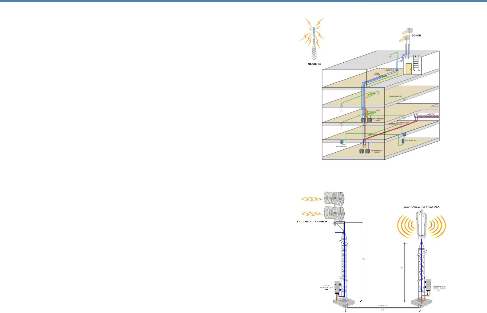
Figure 1 shows an indoor application of repeaters. (I-DAS)
Figure 2 shows an outdoor application of repeaters. (O-DAS)
3
4
2. Introduction
JDTECK has engineered an advanced industrial grade digital repeater for
Distributed Antenna Systems with the ability to function in either a wideband
or narrow band mode. This core component helps create the perfect solution
for providing a wireless improvement in the cellular reception of a large office
or apartment building, hotel, underground parking garage or remote outdoor
location.
It is designed to improve the call quality of an area by receiving, amplifying,
filtering and re-transmitting the signals from the macro base station into a
specified area via a distributed antenna system (DAS.
This highly advanced digital unit uses a Graphic User Interface (GUI) to
access and select the desired active bands or channels, set any alarm trigger
points as well as configure and control the parameters of the repeater which
by extension controls the entire DAS it’s mated to either locally via USB or
remotely via Ethernet.
To maintain safe and specific output power levels, the GUI of this industrial
grade digital repeater has a wide range of configurable settings which allows
the repeater to function strictly within the parameters set by the end user.
These features include built-in Signal Oscillation Detection circuits with
color changing indicators for the respective bands (Green, Orange or Red
depending on the intensity), Automatic Gain Control (AGC) which will
dynamically reduce the gain of the repeater up to 10dB if oscillation or a high
input signal is detected. Manual Gain Control (MGC) to bring the repeater
into a set safe operating limit as well as a Network Safe / Auto MUTE
feature that immediately shuts-down the RF transmission circuit of any
frequency band that exceeds its set output power limits. There is also an
Uplink Sleep mode which shuts down the UL band of the repeater if no
activity is detected on the DAS after a set period of time. All features that
rigorously protect the macro cellular network from harmful interference.
There is master alarm indicator on the header of the GUI as well as an
external LED on the enclosure of the repeater which changes color from
green to red to alert the user if any alarm is detected. The user also has the
option to have the repeater send automatic email or SMS notifications to
specific addresses or numbers alerting the recipients to access the repeater
to make any needed adjustments.
This multiband industrial grade digital repeater from JDTECK is truly a very
user friendly, flexible and highly intuitive device that customers and system
integrators alike will enjoy using for many years to come.
2. Features & Functions
Intuitive GUI with local USB access and remote access via Ethernet.
Stable Performance and Technical Parameters.
Wide range of preset and customized bandwidth options.
IP55 enclosure with large cooling fins for heat dissipation.
External LED indicators that display environmental conditions.
Supports all protocols. (GSM, WCDMA, UMTS & LTE)
ALC function. (Automatic Limit Control – User chooses set limit)
AGC function. (Automatic Gain Control with option to disable)
MGC function. (Manual Gain Control – Up to 40dB)
MUTE auto shutdown function. (Keeps macro network safe)
Uplink Sleep Mode. Shuts down UL if no activity detected after 5 min.
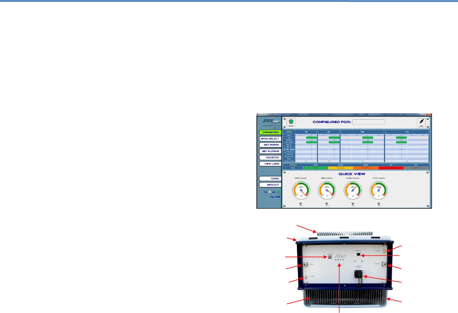
AC Power
Graphic User Interface – Dashboard View
Heat Sink
Cooling
5
6
Bottom View
Mounting
Bracket
LED Indicators
RF OUT
Ethernet
Connection
DL Coupling Port
USB
Connection
RF IN
UL Coupling Port
Heat Sink Cooling
Lockable
Enclosure
3. DAS Installation
1. The repeater’s main function is to improve weak RF signals to an area.
2. Selecting the appropriate accessories that are compatible with this digital
frequency repeater is very important for optimal system performance. Since
this is a multiband repeater, it’s important that all the peripheral components
used in the DAS supports all the frequencies that are going to be needed
and that all the components are Low PIM rated.
3. The signal strength and quality at the donor antenna directly affects the
efficiency of the indoor coverage. Therefore, it is very important to choose
the location of the outdoor antenna carefully. With this in mind, it is
recommended that the donor antenna be installed in clear line of sight
(LOS) to the serving sector/s.
4. The repeater is a two-way (full duplex) digital signal amplifier so, there needs
to be proper isolation between the outdoor antenna and indoor antennas in
order to avoid signal oscillation of the repeater. (Feedback) There needs to
be more than 15dB of isolation above the repeaters gain. For example, if
the repeater gain is 80dB, then you need 95dB of isolation between outdoor
antenna and indoor antenna.
5. The repeater gain is adjustable for both the uplink / downlink individually.
Depending on the environment, the end-user may need to adjust the
repeater gain to achieve optimum performance and desired coverage.
6. The repeater is designed to amplify the input signal, filter it and retransmit it
to the desired area via service antennas. In order to reach the best
performance, the outdoor signal should be better than -80dBm with an Ec/Io
<6 and an RSRQ of <12dB. If the outdoor signal is very weak, then a pre-
amplifier may be used.
7. Calculating the Link budget before setting the repeater gain.
Link budget calculation:
Outdoor signal strength – Loss of accessories (cable, connectors, splitters,
Directional Couplers, Path Loss) + Antenna gain (outdoor antenna, indoor
antenna) + Repeater gain = Indoor signal strength.
8. For all cellular applications, you should only use 50 Ohm rated coax.
Besides affecting voice quality, using any other impedance of coax will
affect the throughput performance of services over LTE as well as shorten
the life of the repeater.
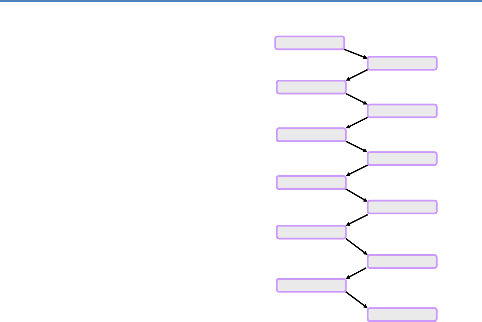
3.1 Installation Procedure
Site Survey
Carrier Coordination
Link Budget
Calculation
Retransmit Agreement
Install Donor Antenna
Install Cables & Sweep
Install Repeater
Install Indoor Antennas
Commission System
Gain Adjustment
Call & Data Quality
7
8
System Optimization
3.1 Installation Procedure – Cont.
Check the contents supplied against your packing list & DAS design.
Identify a suitable location where the donor antenna will be installed on
the roof or at an elevated location free of any other antennas or
immediate obstructions. Confirm this location has the best input signal
for the carriers you would like to support using test equipment. Ensure
the location is properly isolated from any of the indoor service antennas
so as to avoid signal oscillation.
Identify the location for the head-end equipment and that suitable AC
power and a lightning ground is available. Using the DAS design
provided, walk the entire space to confirm all the components and cable
access paths of the DAS can be installed without any omissions.
Install the donor antennas at the suitable location identified and start the
cabling process. DO NOT COIL UP any excess coax or create any
service loops in your system. These are detrimental to cellular
performance. Be sure to weather proof all your external connections and
fire stop all ports of entry.
Carefully follow your DAS diagram to ensure all the components are
installed according to the design. Any alterations made to the system
layout without informing the DAS design engineer could result in poor
system performance or interference to the macro.
It’s EXTREMELY IMPORTANT that all your cable terminations be done
properly and line sweeps completed using the appropriate test
equipment. (Frequency Return Loss) Directional couplers MUST be
installed in the right direction and with the correct values as outlined in
the DAS design. DOUBLE-CHECK ALL YOUR WORK! The extra time
you invest to do so will pay-off with a smooth and successful
commissioning process.
If multiple repeaters are deployed, start by commissioning one repeater
at a time. It’s best to start with the frequencies that support voice
communication, then move on to data (4G, 5G, LTE). Upon
commissioning, quickly work towards getting the LEDs on the repeater to
a green status by adding attenuation as needed. First on the DL, then
on the UL.
If signal oscillation or a strong input signal is between 1~4dB over the
acceptable range then the field alarm for the respective band will turn
orange (See manual gain adjustment). If the signal oscillation is between
10-15dB then the field alarm for the respective band will turn red and the
circuit will then go into MUTE / Shutdown (Grey). This is as a result of
not having enough isolation between the donor and service antennas or
the input signal at the donor antenna is too strong.
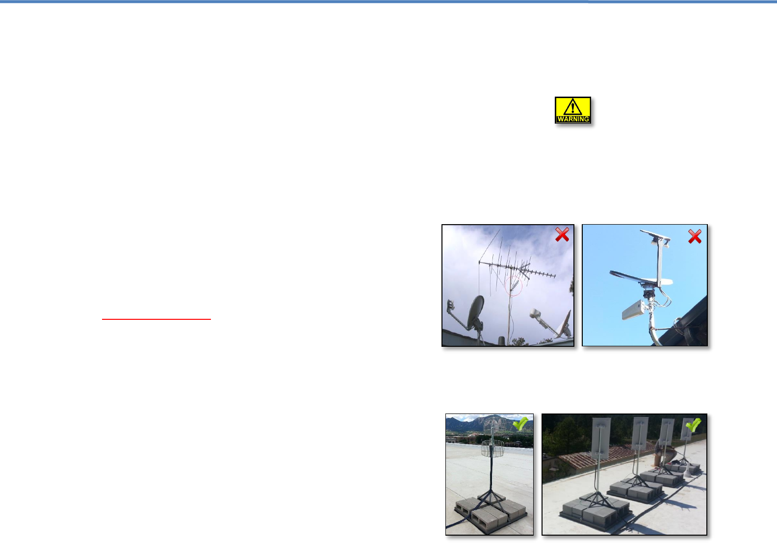
3.2 Installation Procedure – Antenna Mounting.
In this case, attenuate the DL gain on the repeater and then match the UL
gain to the same gain value. After each gain adjustment is made, click the
power cycle tab on the GUI. This will take the repeater out the MUTE /
Shutdown state. (See attenuation settings for adjustments)
"The installation height of the antenna for AWS band (1700/2100 MHz)
operations is limited to 10 meters above ground for compliance with 47
CFR 27.50
Do not install the donor antenna near high voltage power lines.
Please take the necessary safety measures when working on heights.
Do not mount near or in the path of other antennas or satellite dishes.
It is recommended that you mount your donor antenna in a spot that is
free of any immediate obstructions. Making use of a dedicated mast or
mounting bracket is recommended for optimum antenna performance.
9
10
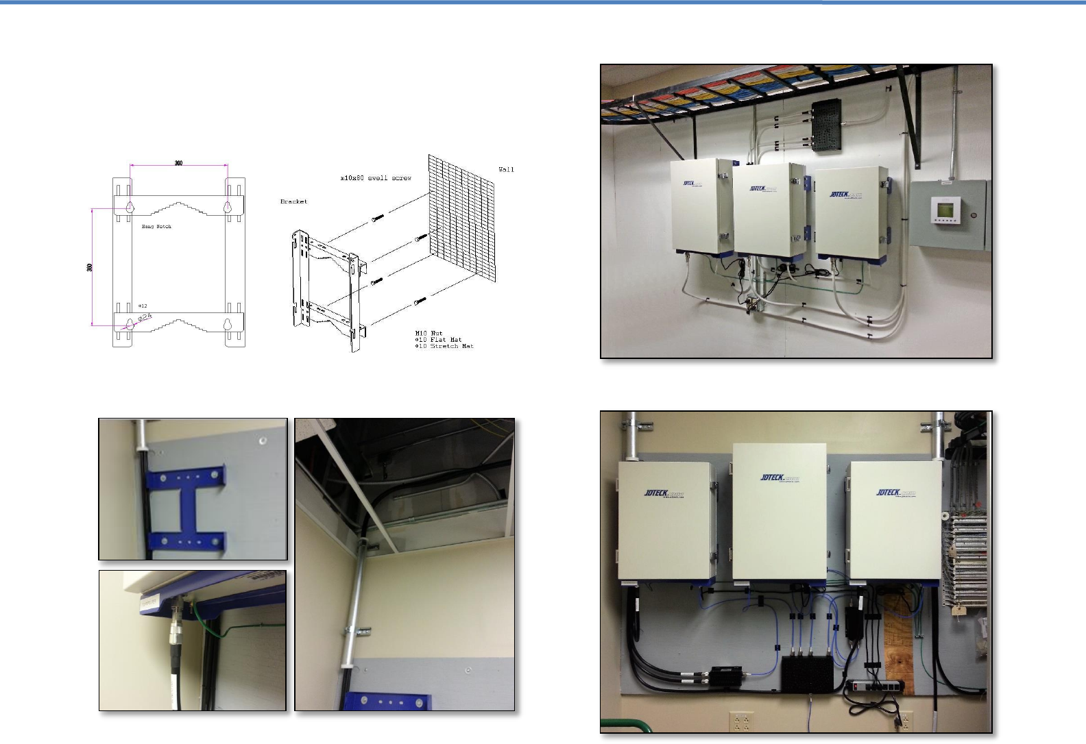
3.3 Installation Procedure – Repeater Mounting.
The JDTECK industrial digital repeater is designed to be mounted on a wall.
Carefully remove the repeater from the box and place it upright on a
protected surface like cardboard or carpet. Then remove the mounting
bracket from repeater and securely bolt bracket to the wall. Be sure to use a
plumb level so the bracket is perfectly straight when completed.
Install conduit from above ceiling to communications board, route coax
through conduit, then slide repeater onto bracket.
3.3 Installation Procedure – Repeater Mounting Cont.
Always dress in and label cables properly so communications
board looks neat and professional.
11
12
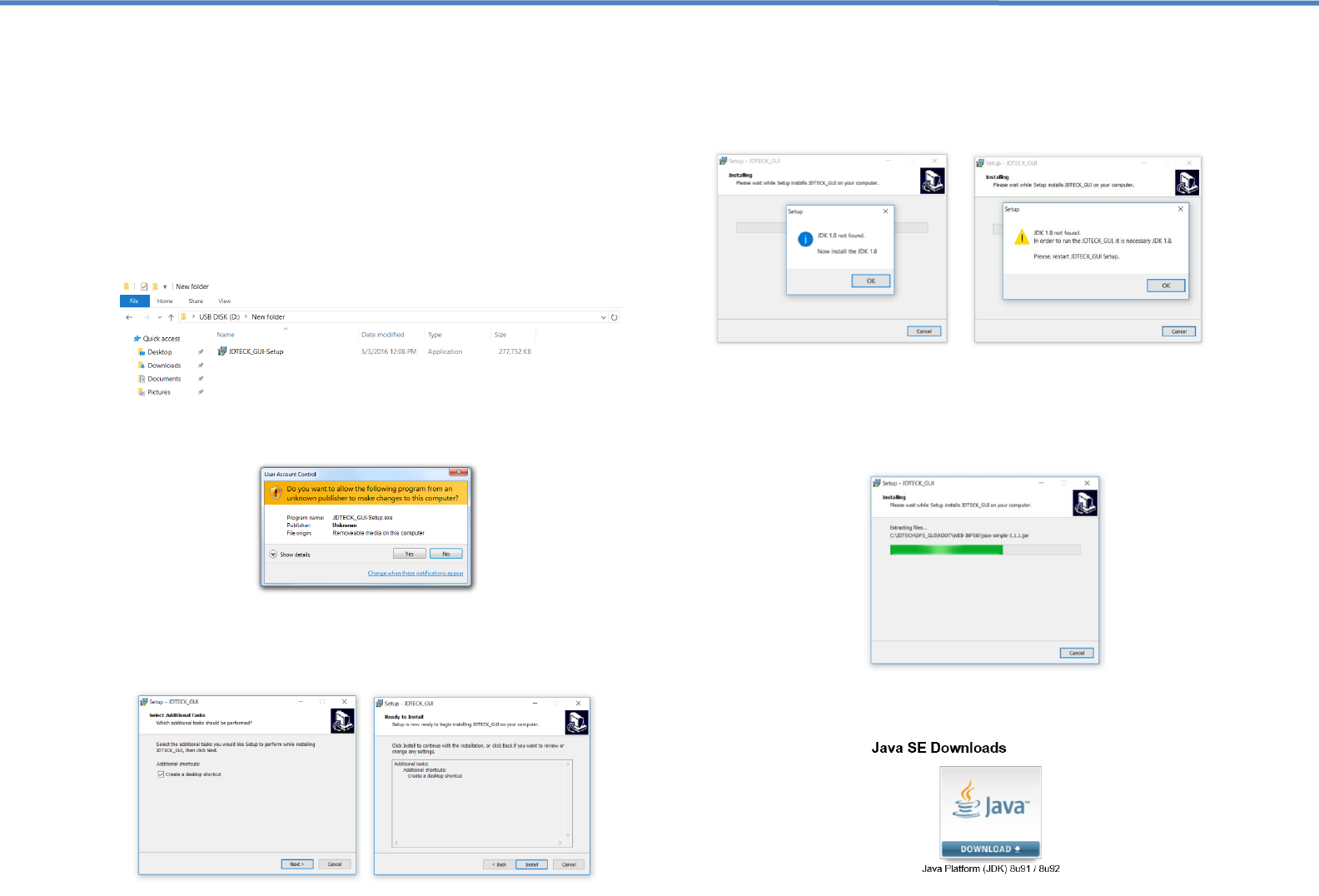
4. Installing the Graphic User Interface. (GUI)
A USB thumb drive is shipped with each repeater which has the GUI program
stored on it. Install the GUI program onto a Laptop PC that will be used to
initially access and configure the repeater. Please note that the GUI can only
be initially accessed via a USB cable connection. You will also need to have
an internet connection to download Java.
Click on file name JDTECK_GUI.exe to install program. Please allow a few
seconds for process to start.
The following error will most likely pop up. Go ahead and click yes.
You will then be prompted to start the install sequence. Click next. Be sure to
leave the check box selected to create a desktop shortcut.
4.1 Installing the GUI. (Con’t)
Java Development Kit is required to run the GUI. If none is detected, you will
be prompted to install it. Click OK on both windows.
The install sequence will begin and complete, however you will again be
prompted to install Java Development Kit (JDK). The second time,
a link to Oracle’s website will launch.
On the Oracle site, click on the following link.
12
13
2
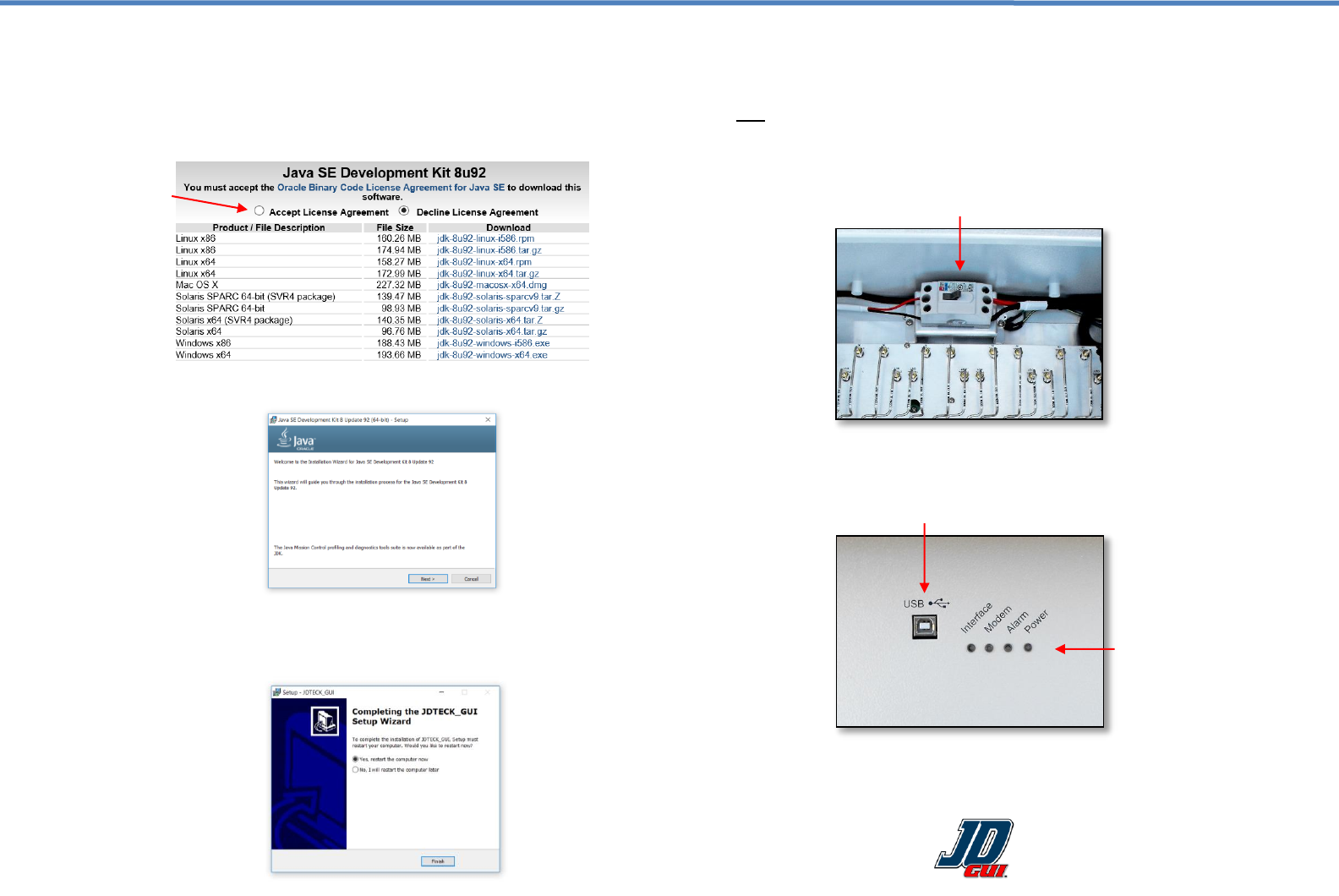
4.2 Installing the GUI. (Con’t)
You will then be show several options to choose from. Scroll down to Java
SE Development Kit 8u92 and select “Accept License Agreement”. Then
choose the operating system compatible with your PC.
After selecting the appropriate operating system, click next.
After you have installed Java, you will be prompted to restart your PC. Please
do.
4.3 Accessing the GUI.
After you have installed the GUI program and restarted the PC, the user will
first switch the repeater ON and wait for the boot sequence to complete.
This is indicated by the LED’s at the bottom of the repeater. The LED’s turn
from RED to GREEN. This will take about 1-2 min.
After the LED’s turn green, connect the supplied USB cable to the repeater
and your PC.
Next click on the JDTECK GUI Icon.
Main Power Switch
Connect USB
LED Indicators
Click Here
14
15
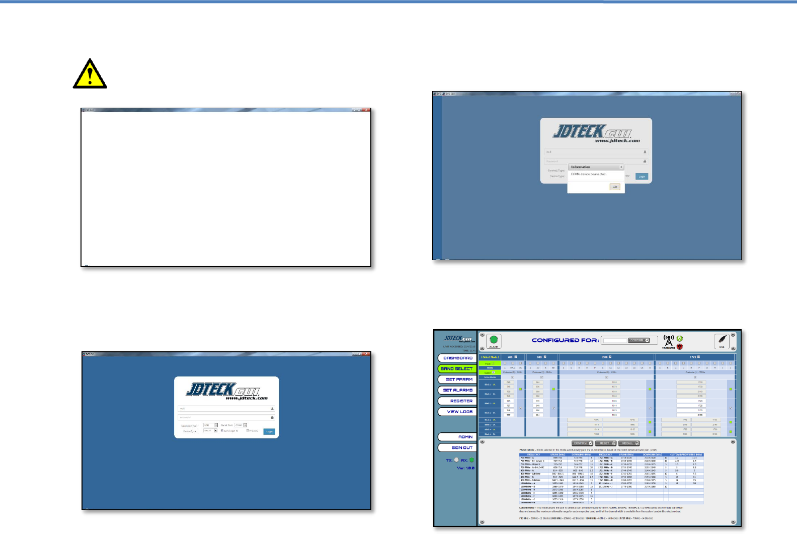
4.4 Accessing the GUI. (Con’t)
If the GUI screen comes up blank, it’s because Java did not install
correctly. It would be easiest to just reinstall the program again
from the thumb drive where you would again be prompted to
download the correct Java Kit and restart the install sequence.
Upon a successful installation, the following screen will appear. Here you will
select the connection type (USB), the device type (DR-27) and the COM
Port. This is typically COM Port 4, however you can double check by going
to Device Manager on your PC to see which port is active.
4.5 Accessing the GUI. (Con’t)
When the correct COM Port has been selected, the following screen will
appear. Click OK to proceed.
The first screen to appear is the Band Select Page. On this page, the user
will select which bands they want to support. You also have the option to
assign the repeater a name or ID on this page at the header.
16
17
5. Using the GUI. (BAND SELECT)
The GUI is inherently intuitive and very user friendly. The user simply selects
the bands they would like to support and click confirm. They can choose from
either the preset band selections or customize a selection as needed. In the
custom selection mode, the user can select all the bands at the very top
which will activate all the blocks within the bands. This will allow the repeater
to run in wideband mode. (All Channels in All Bands). Ideal for enterprise
deployments where the user would like to support all carriers.
The user also has the option to select multiple non-contagious blocks or
channels they would like to support. (2) for 700 MHz, (2) for 800 MHz,
(4) for 1900 MHz and (4) for AWS. These are typically used in carrier
applications. No matter which options are selected, the user must remember
to click CONFIRM for the GUI to register the selection. Please note that
clicking CONFIRM will NOT send the repeater into transmission mode, it will
only log the data inputted or selected. This allows the user to continue with
setting up the parameters and alarms for the repeater even before going live
with transmission.
There are several other neat features you will notice on the header as well as
internal of each page. These include:
A MASTER ALARM on the top left which is synced with the alarm LED on
the outside / bottom of the repeater enclosure so even if the user is not
logged into the GUI, they can observe if an alarm is present or not.
A dynamic ICON on the top right of the GUI that indicates how the user is
interfaced with the GUI. Either via USB or Ethernet.
A CONFIRM button that registers the selections on each page.
A RESET button which resets all the settings on that page to factory default.
A RECALL button which will repopulate the fields with the last saved
selection.
Bold, easy to view, color changing navigation tabs on the left so at any time
the user knows which page they are on or where to navigate to next.
A dynamic TX & RX status indicator to show communication activity between
the GUI and the repeater.
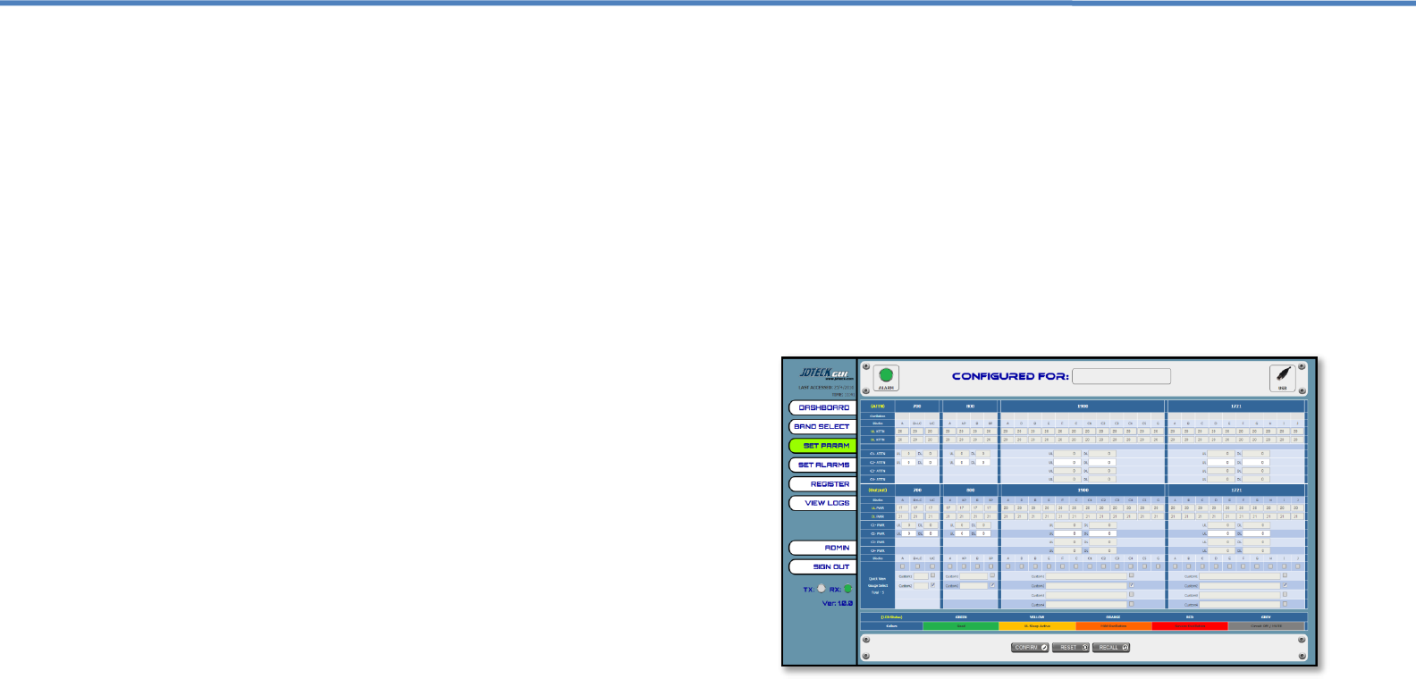
5.1 Using the GUI. (SET PARAMETERS)
The SET PARAMATERS page allows the user to set the high-limit (not to
exceed) points of the repeater on the bands that were activated on the
BAND SELECT page. Only the active band fields are editable. The user
can individually adjust the UL and DL attenuation values which directly
influences the Output Power for each respective band. This page also
displays the status color of the respective band so the user knows which
band to adjust. Once on this page, the response to the adjustment is not
dynamic, so the user will need to click on the dashboard to see the effect.
Also working fixed within the program is an Automatic Gain Control
feature (AGC) which dynamically adds attenuation to the respective band to
maintain the output power limit set by the user for UL and DL.
Because the repeater has dynamic AGC, the status fields will only change
color from Green to Orange or Red when the AGC threshold has been
exceeded. An infringement that is between 1-5dB over the AGC range will
change color from Green to Orange. If between 6dB and 10dB, it will
change to Red. If above 10dB, the respective circuit will go into active
MUTE / Shutdown. To get the unit out of MUTE, first add more DL
attenuation to the respective circuit, power cycle the repeater’s transmit
circuit and then click on the DASHBOARD to see the change. The fields on
this page come preset from the factory with the following values:
20dB of attenuation on the UL and DL.
17-20dBm Output Power Limit for the UL.
21dBm Output Power Limit for the DL.
18
19
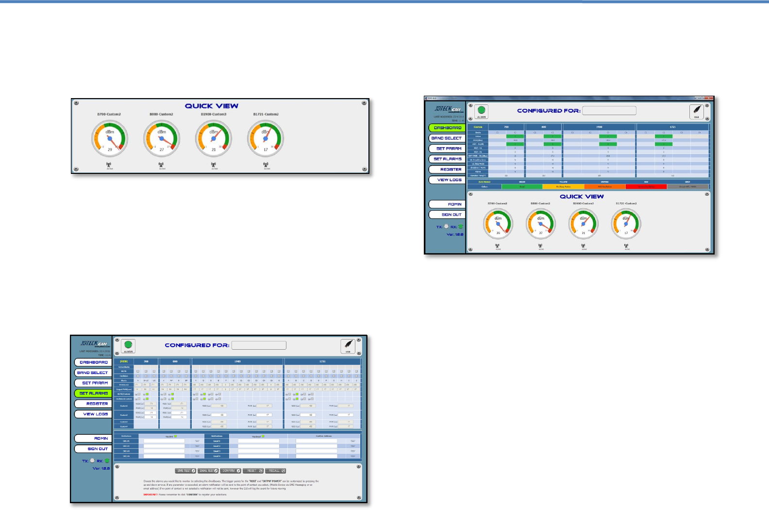
5.2 Using the GUI. (SET PARAMETERS)
On this page, the user also has the option to select up to any 5 bands they
would like the QUICK VIEW DIALS to monitor which dynamically display the
DL output power over on the DASHBOARD page.
4. Using the GUI. (SET ALARMS)
On the SET ALARMS page the user can set the trigger points for when an
alarm will activate and display RED or optionally send an automated
notification out to as many as 4 users simultaneously. The parameters
monitored on this page include Low RSSI, Low Output Power, MUTE
activation and Signal Oscillation. The user can define what they consider to
be a low threshold point when an alarm should be triggered and a notification
sent for the RSSI and Output Power limit. They also have the option to select
if they want a MUTE or Oscillation notification sent out as well. If the email
and SMS fields are not populated, alarms will just be displayed and logged.
5.3 Using the GUI. (DASHBOARD)
The DASHBOARD page provides an overview of how the repeater is
functioning. The view of this page dynamically changes depending on if the
repeater is operating in preset or custom mode.
The RSSI, AGC, MGC, Output Power, UL Overdrive, UL Sleep, MUTE,
Alarms, Operating Temps and Quick View Dials are all dynamically
displayed in real time on this page. The user gets to see when the output
power exceeds the set limits and exactly how much AGC is being added to
keep the repeater within the set output power limit range, as well as when
any threshold limit is exceed which will then send the respective circuit into
active MUTE / Shutdown.
Because of this, it allows the user to easily determine exactly how much
additional MGC is needed to prevent the repeater from going into active
AGC mode and maintain a stable output.
This page also has a unique feature called an UL Overdrive Alarm. This
alarm was designed for scenarios where the DAS is also providing coverage
to an underground parking garage and someone enters the garage with an
in-car signal booster which inadvertently sends the respective UL circuit
beyond its set UL limit. The repeater detects this and immediately adds AGC
to the respective circuit in order to protect the macro from severe
interference. If the AGC range is exceeded (10dB) the respective circuit
then goes into MUTE and then attempts the auto restart sequence.
20
21
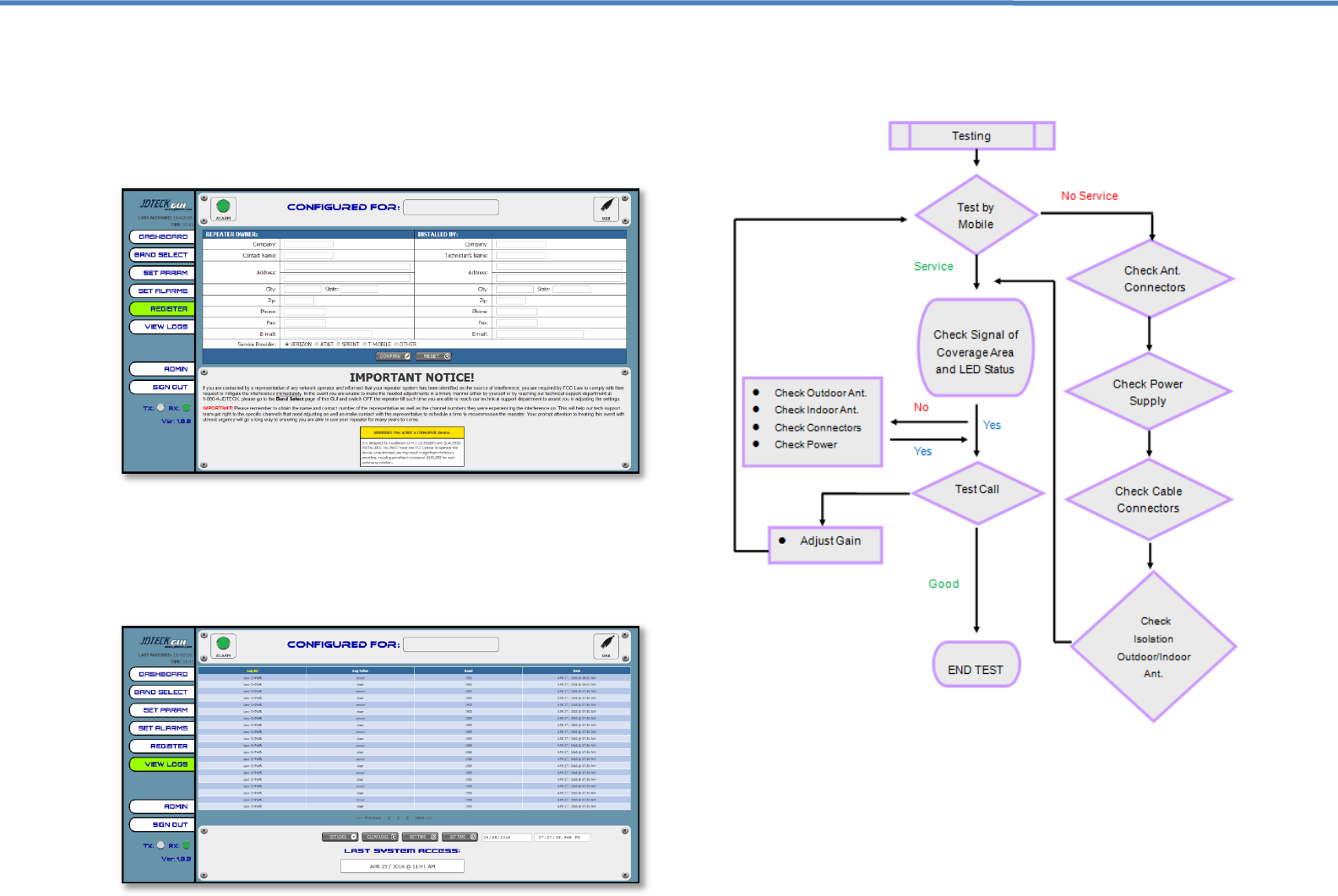
5.4 Using the GUI. (REGISTER)
The REGISTER page allows the user to document the contact details of who
owns the repeater as well as who installed it.
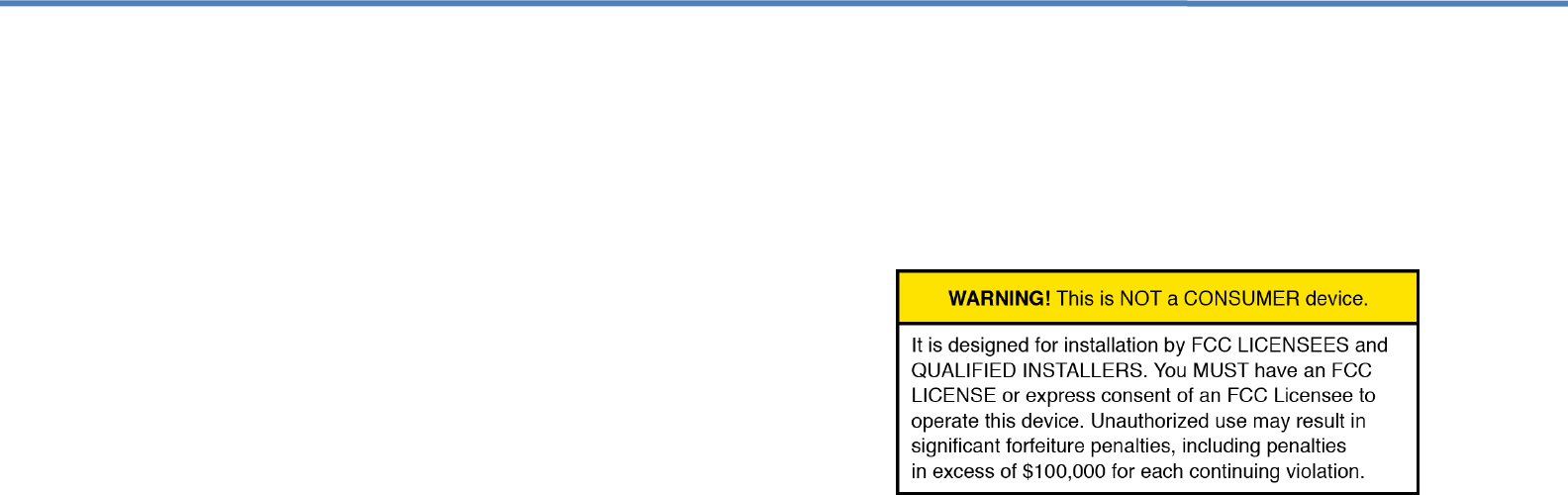
A warning label is also displayed on this page.
5.5 Using the GUI. (VIEW LOGS)
The VIEW LOGS page allows the user back and review the type, value,
band, date and time an alarm occurred. They also have the option to
download the logs to excel.
6. Testing. (Flow Chart)
22
22
IMPORATNT SAFETY INFORMATION
The outdoor antenna used for the purpose of communicating to the wireless
infrastructure is limited to 23 dBi, or any combination of gain and loss that equates
to 23 dBi at output. Each antenna must be positioned to observe minimum
separation requirements from all users and bystanders.
The following guidelines should be used when considering separation distances.
INDOOR antennas must be placed such that, under normal conditions, personnel
cannot come within 20 cm from any inside antenna.
OUTDOOR antenna must be positioned such that, under normal conditions,
personnel cannot approach closer than 103 cm. A directional antenna having a
maximum gain of 23 dBi is used, precautions should be taken to prevent personnel
from routinely passing closer than specified.
7. Troubleshooting
Q1. Why is there still no signal after installing the equipment?
Answer:
1. Check the power on repeater and power supply.
2. Check the connector of outdoor antenna is tight or not.
3. Check the connectors of RF cable are tight or not.
4. Check the outdoor signal is strong enough or not.
5. Check to make sure the antenna is installed correctly.
6. Check the connector of indoor antenna is tight or not.
7. Check the cable type is suitable or not.
Q2. Why the signal strength is too weak on the edge of area?
Answer:
1. Check the outdoor signal and antenna direction.
2. Check repeater is full gain or not.
3. Check all of the connectors are tight.
4. Change the location of outdoor/indoor antenna.
5. Check the cable type is suitable or not.
6. Deploy more indoor antennas.
Q3. Why can’t I make a call after installation, even though I can
detect a signal?
Answer:
1. Check LED status of repeater to make sure alarms are green.
2. Change the location of outdoor / indoor antenna.
3. Reduce the UL gain of the repeater.
Q4. The signal is not stable after turning on the repeater power.
Answer:
1. Check to see if the outdoor signal is stable or not.
2. Check the location of the donor antenna. Too close to other antennas.
3. Check the RF cable is broken or not and has no coils.
4. Confirm direction of donor antenna in relation to cell tower.
8. FCC Statement
1. FCC RF Exposure Statement
This equipment complies with FCC radiation exposure limits set forth for an uncontrolled
environment. End users must follow the specific operating instruction for satisfying RF
exposure compliance. This transmitter must not be co-located or operating in
conjunction with any other antenna or transmitter.
2. FCC Warning
For North American Market.
23
24
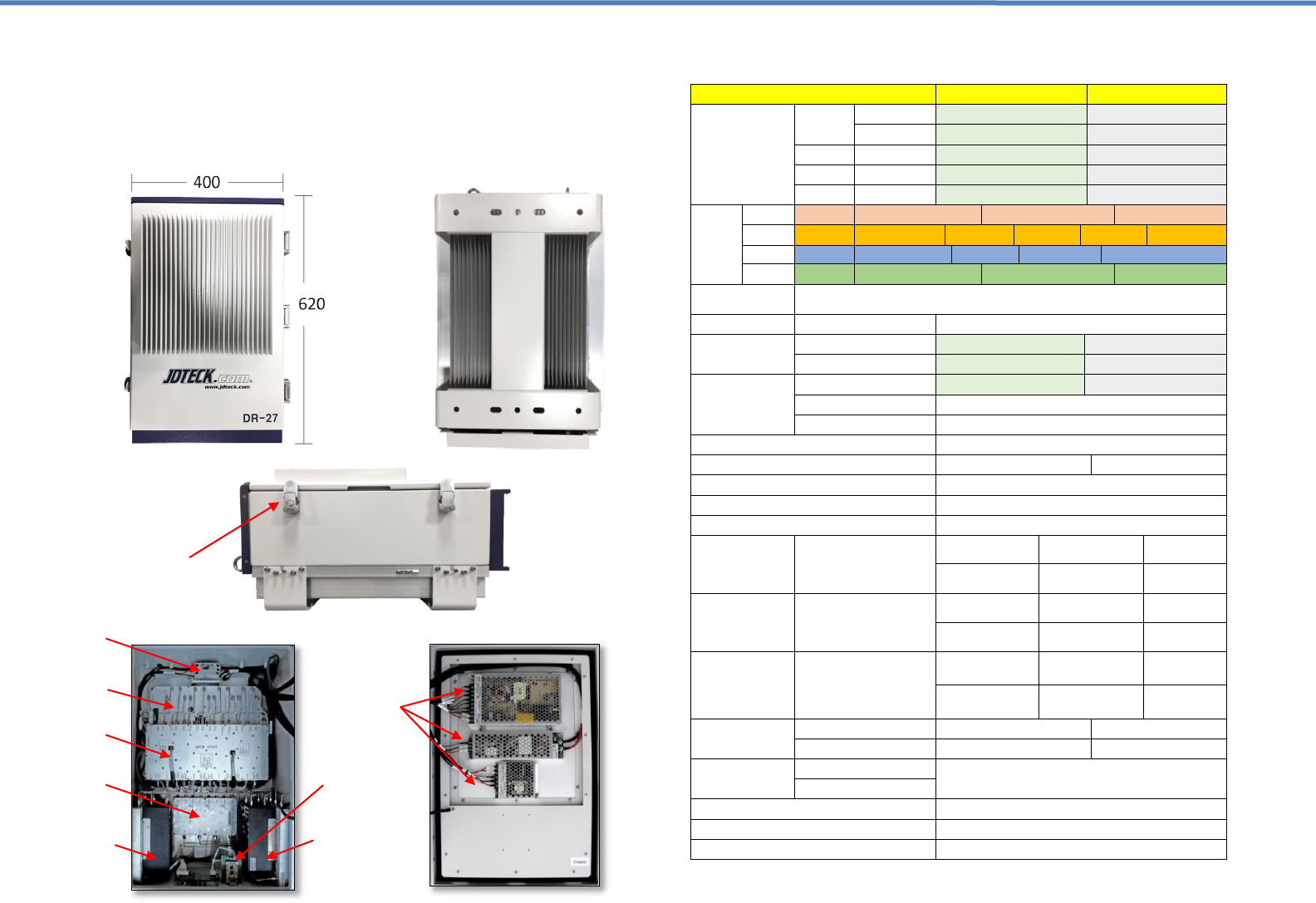
9. Specifications. (Enclosure)
The JDIR-LCPA-DR27 Quad Band Digital Repeater is built in a solid
enclosure resistant to dust and is lockable. To maintain safe operating temps,
there is heatsink lining both the front and rear of the enclosure. Mounting
brackets allow this unit to be installed on a wall.
9.1 Specifications. (Data)
Frequency Specifications
Uplink
Downlink
Frequency Range
700 MHz
18 MHz
698 ~ 716 MHz
728 ~ 746 MHz
11 MHz
776 ~ 787 MHz
746 ~ 757 MHz
800 MHz
25 MHz
824 ~ 849 MHz
869 ~ 894 MHz
1900 MHz
65 MHz
1850 ~ 1915 MHz
1930 ~ 1995 MHz
1721 MHz
70 MHz
1710 ~ 1780 MHz
2110 ~ 2180 MHz
Preset
Filter
Options
1 to 2
700 MHz
29M (A+B+LC+UC)
6M (A,B,LC)
11M (UC)
1 to 2
800 MHz
25M (A+B+A'+B')
11M (A)
10M (B)
1.5M (A')
2.5M (B')
1 to 4
1900 MHz
65M (A,D,B,E,FC,G)
15M (A,B,F)
7.5M (C1, C2)
5M (D, E, F, C3, C4, C5,G)
1 to 4
1721 MHz
70M (A,B,C,D,E,F,G,H,I,J)
10M (A,B,F,J)
5M (C, D, E, G, H,I)
Customizable
Bandwidth Options
1.2MHz, 1.23MHz, 1.25MHz, 1.4MHz,1.5MHz, 2.5MHz, 3MHz, 3.5MHz, 3.8MHz, 5MHz
6MHz, 7.5MHz, 10MHz, 11MHz, 14MHz, 15MHz, 18MHz, 20MHz
Effective Bandwidth
Custom Bandwidth 900 KHz
All Bands
Output Power
700 / 800 MHz
+17dBm Each Band Total
+24dBm Each Band Total
1900 / 1721 MHz
+20dBm Each Band Total
+27dBm Each Band Total
Gain
Range
52~92 dB
52~88 dB
Adjust step
1dB
Adjust Accuracy
+/- 1dB
Gain Variation Over Temp.
+/- 2dB / Ambient Room Temp
Adjacent Channel Power Compensation Level
N/A
< 15dB – Downlink
Noise Figure
<7dB @ Max Gain
Impedance
50 Ohm
Propagation Delay
<6usec
CDMA Spurious
Emission
>45dBc@+/- 750KHz
>50dBc @+/-1.98MHz
700 / 800 MHz
1 Block @ 20dBm
1 Block @
34dBm
1900 / 1721 MHz
1 Block @ 23dBm
1 Block @
37dBm
ACLR (LTE)
>45dBc@+/- 5MHz,
>45dBc @+/-10MHz
700 / 800 MHz
1 Block @ 20dBm
1 Block @
34dBm
1900 / 1721 MHz
1 Block @ 23dBm
1 Block @
37dBm
ACLR (WCDMA)
>45dBc@+/- 5MHz
>45dBc @+/-10MHz
700 / 800 MHz
1 Block @ 20dBm
1 Block @
34dBm
1900 / 1721 MHz
1 Block @ 23dBm
1 Block @
37dBm
Gain Flatness
700 / 800 MHz
<6dB p-p ( Total Bandwidth )
<3dB p-p (Each block)
1900 / 1721 MHz
<8dB p-p ( Total Bandwidth )
<3dB p-p (Each block)
EVM
LTE
<8% ( Including Source Signal )
WCDMA
VSWR
<1.5:1
Wave Form Quality (p) ~ CDMA
>0.98
FCC ID
SQX-JDIR-LCPA27
25
26
Power
Switch
Power
Supplies
Digital
Board
RF
Module
DL Power
Amp
Ethernet
Module
Donor
Multiplexer
Lockable
Enclosure
Service
Multiplexer
NOTES
_________________________________________________________________________________
_________________________________________________________________________________
_________________________________________________________________________________
_________________________________________________________________________________
_________________________________________________________________________________
_________________________________________________________________________________
_________________________________________________________________________________
_________________________________________________________________________________
_________________________________________________________________________________
_________________________________________________________________________________
_________________________________________________________________________________
_________________________________________________________________________________
_________________________________________________________________________________
_________________________________________________________________________________
_________________________________________________________________________________
_________________________________________________________________________________
_________________________________________________________________________________
_________________________________________________________________________________
_________________________________________________________________________________
_________________________________________________________________________________
_________________________________________________________________________________
_________________________________________________________________________________
_________________________________________________________________________________
_________________________________________________________________________________
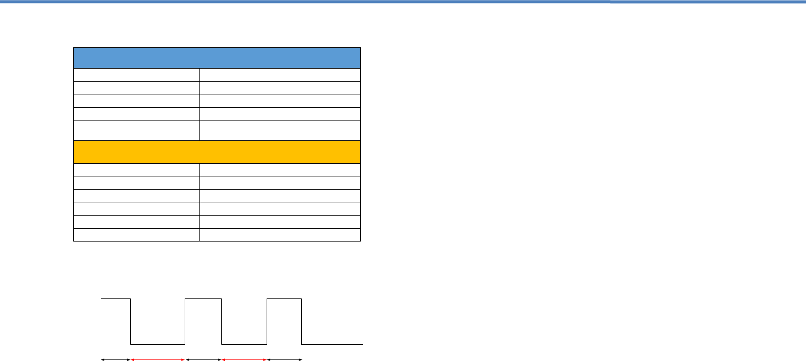
9.2 Specifications. (Features & Environmental)
FEATURES
Automatic Gain Control Range (AGC)
≥10dB
Manual Gain Control Range (MGC) ~ Via GUI
≥40dB
Automatic Limit Control (ALC)
Will not exceed max. output power of repeater
Automatic Shutdown (MUTE)
Circuit will shut down if limit is exceeded
Uplink Sleep Mode
When no mobile is detected in range of service antenna, UL will
go into sleep
ENVIRONMENTAL
Power
AC 110V~220V
Operating Temp.
-10 ~ +55'C
RF Connector
N-Type Female (RF IN / OUT), SMA Female (Coupling Port)
Coupling port
20dBc +/- 3dB
Environment Condition
Indoor type
Ext. Interface
RJ 45 , USB B, SMS Connection
9.3 MUTE / Shutdown Cycle Sequence.
10. Abbreviations.
AGC – Automatic Gain Control.
ALC – Automatic Limit Control.
DAS – Distributed Antenna System.
DL – Downlink.
GUI – Graphic User Interface.
LED – Light Emitting Diode.
MGC – Manual Gain Control.
MUTE - Shutdown.
RSSI – Receive Signal Strength Indicator.
UL – Uplink.
18
27
28
AGC Atten value
over 10dB
Shutdown
5 seconds 30 seconds 5 seconds 30 seconds 5 seconds
Complete
Shutdown