JTECH Communications INTELFLEXBS Base Station User Manual
JTECH Communications, Inc. Base Station
User manual
1
Installation, Programming and Operator Guide
Part Number 320XXXC
IntelFlex TM Controller
o Base Station
2
Introduction:
Congratulations on your purchase of a JTECH Message System containing the IntelFlex
Controller. Please take a few minutes to review this manual prior to installing and
operating your system.
Please inspect the System upon receipt. If the contents appear to be damaged, notify
the shipper immediately to file a claim and notify JTECH Customer Care. If components
are missing, contact JTECH Customer Care.
If you have any questions or need assistance, please call JTECH Customer Care at 800-
321-6221 or 561-997-0772, option 6.
IntelFlex TM Controller
Base Station
3
4
5
6
7
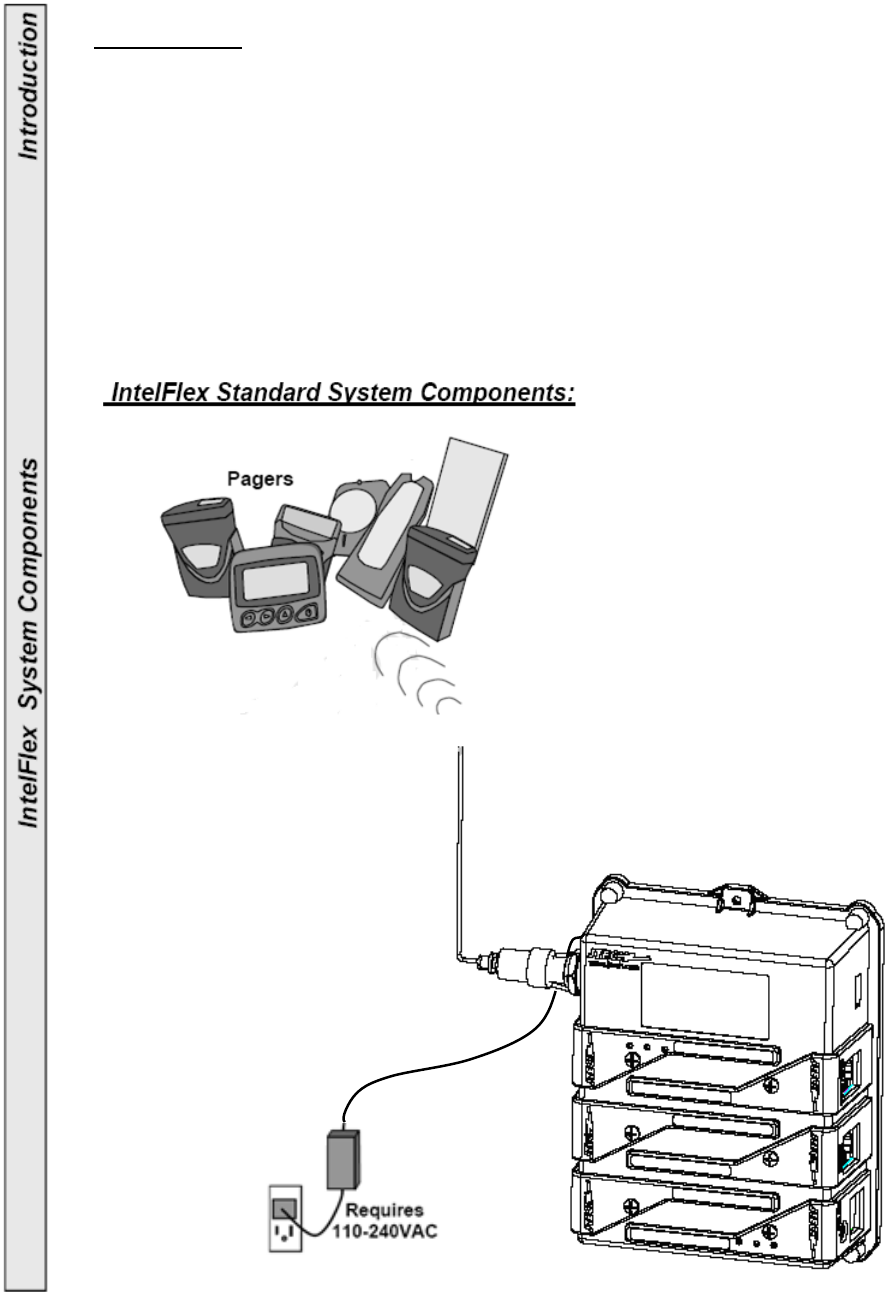
General Specifications (Includes Optional Expansion Modules):
DC Operating Voltage: 13.5VDC 2.4A
Power Adaptor: 110-240VAC 50-60Hz power adaptor
Controller RF Power Output: 0.1-2 Watts - adjustable using 5 levels
Modulation: FSK 512BPS
Protocol: POCSAG
Transmit: 512, 1200, 2400 Baud
Maximum Expansion Modules: 6 (Any combination; RS232, Telco or Contacts)
RS232 Module (Optional): 1200 Baud, No parity, 8 Data bits, 1 Stop bit
(for JTECH protocol and up to 115,200 Baud for TAP)
Telco Module (Optional): REN=0
Contact Module (Optional): NC/NO 4 Pair. 100Ft Maximum wire length.
Antenna Port: 50 Ohm BNC
Gain of antenna: 2.0dBi max.
Antenna type: Monopole antenna
Operating Frequency: UHF synthesized 435-470MHz
Temperature Stability: -22° to 122°F (-30 to 50°C) at better than 5 ppm
Weight: 1.95-2.25 Lbs (0.89-1.02kg) – Depending on options
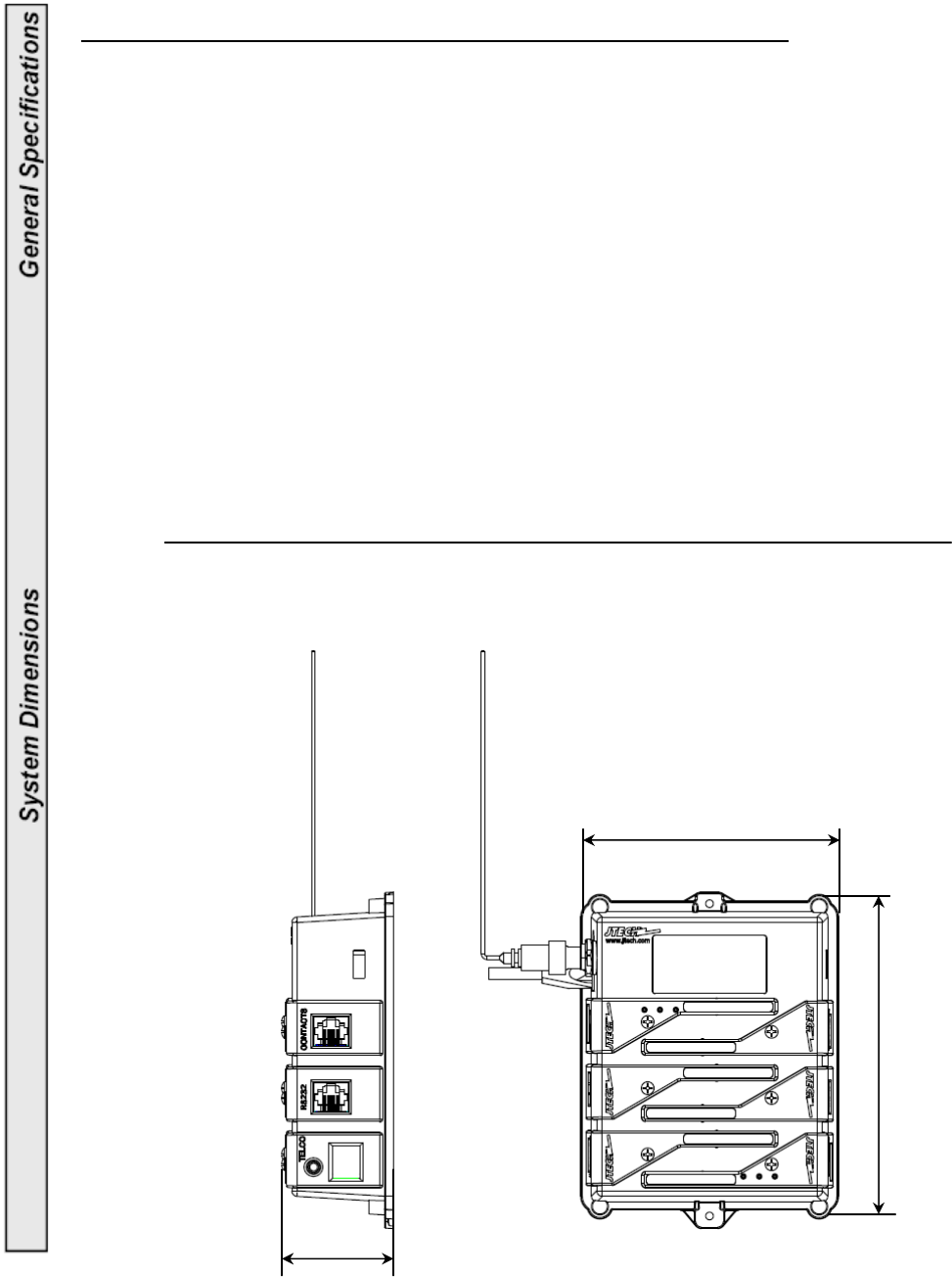
Base Station Dimensions
113.7mm
137.5mm
46mm
8
IntelFlex Controller Highlights:
• Built in transmitter for paging Vibe/ Tone/ Flash, Numeric and Alphanumeric
Pagers.
• Send canned and user defined messages to Alphanumeric and Numeric Pagers.
• Adjustable RF power settings from 0.1-2.0 Watts.
• Time stamped events and an exportable Log (.txt format) are available.
• 6 expansion slots allow for increasing capabilities.
• “Monitor Before Transmit” eliminates missed pages caused by surrounding
equipment.
• Queues up to 32 messages with priority.
• Supports past and present JTECH Transmitter functions and more:
•Out-of-Range: Warn when the Pager is moved out of transmission range.
• Range Test: Measure, establish and adjust transmitter range.
• Search Mode: Find lost Pagers.
• Group and Dynamic Group Paging: Page several Pagers with a single entry.
• Call4Sure: Cell phone paging.
• Replace Pager: Change Pager numbers as needed.
• Pager Voice: Turns Pagers voice alerts ON or OFF.
• Change alert vibration settings.
Range:
•Maximum transmitter range is 1.5- 2 miles (2.4 – 3.2km).
• Range will vary, depending on the equipment location and surrounding
environment.
• Increase range with an optional Magnetic Mount Antenna, 6ft Antenna or
Extended Range Kit (FCC license required).
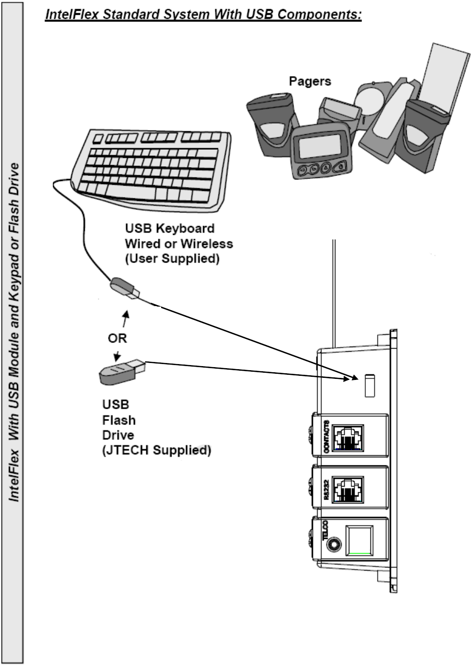
USB and Ethernet Connection:
•USB 2.0 port for Flash Drive software upgrades or keyboard support.
• IP addressable Ethernet port for paging support “online” and software upgrades.
9
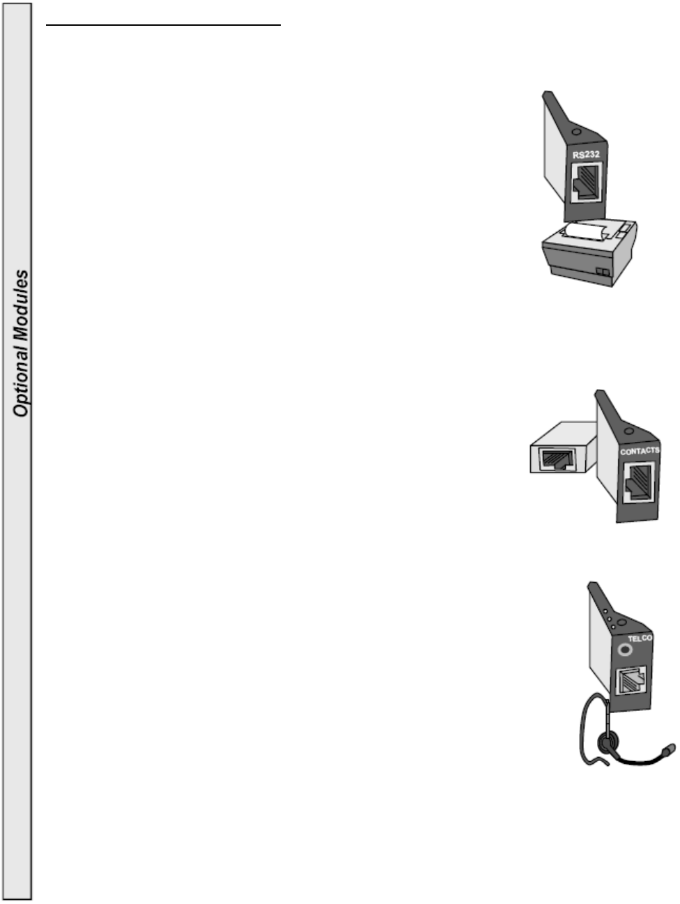
Optional Expansion Modules:
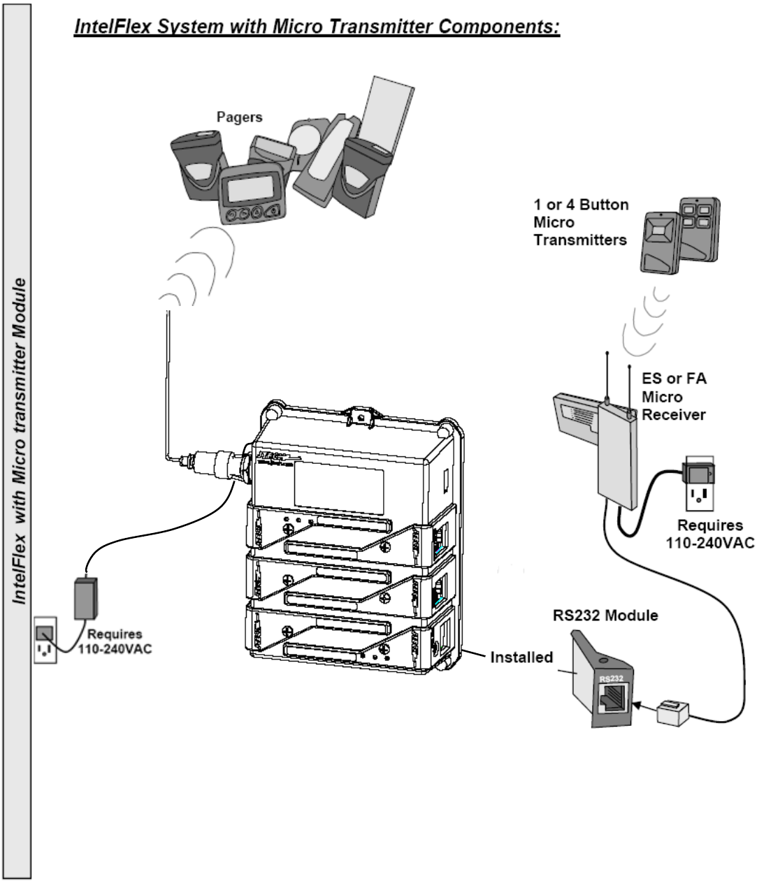
RS232 (Communications):
• Supports existing JTECH RS232 Interfaces including
Smart Alert Transmitters.
• Receives TAP (Telocator Alphanumeric Protocol) at
various baud rates.
• Receives data input at up to 115,200 Baud.
• Connect to a computer to send page information to
Vibe/Tone, Numeric and Alphanumeric Pagers.
• Connect to a Thermal Printer to print Call4Sure
receipts and phone lists.
• Develop special applications (User software and interface
development may be required).
• Includes a RJ45/RS232 adapter cable.
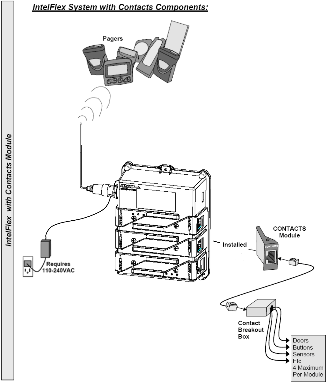
CONTACTS (Contact Closure):
• Each Module supports up to 4 buttons/contacts.
• SPDT Connections
• Normally Open (NO) or Normally Closed (NC) programmable
contacts.
• 25 feet (7.6m) of Cable and Contact Breakout Box included.
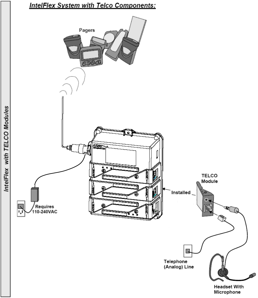
Call4Sure:
• Use with Call4Sure functions to send messages to cellular
phones.
• Requires a dedicated analog phone/fax line for each TELCO
Module installed.
• Outgoing calls will queue.
• Customize voice messages and monitor calls using the included
Headset with Mic.
10
6
’
(1.8m)
M
agneti
c
M
ount
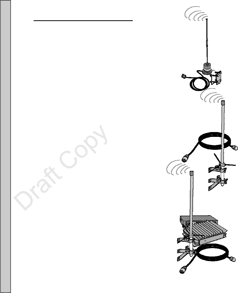
Antenna Choices to Extend Range
(Requires FCC licensing)
---- current Desktop controller is for indoor use.
Outdoor antenna function is not considered at this time
• 3 Ft (0.9m) Magnetic Mount Antenna with
12ft (3.6m) Cable: All metal indoor/outdoor
Antenna with a magnetized base for mounting to
steel or iron. Wall mounting hardware included for
wall mounting to non magnetic surfaces.
•
6ft (1.8m) Antenna and 25ft (7.6m) Cable:
Fiberglass indoor/outdoor Antenna which can mount
to any stable surface. Wall mounting hardware included.
•
Extended Range Antenna Kit:
Includes a 6ft (1.8m) fiberglass indoor/ outdoor Antenna,
35watt Power Amplifier, Power Supply and 50ft (15m) or
100ft (30m) Cable. Increases the output of the IntelFlex’s
Controller to 35 Watts and range of up to 5 miles (8km).

11
Connect your system for testing.
1. Connect the Antenna and point upward (vertical).
2. Connect the USB port to USB keyboard and RS232 port to PC.
3. Plug in the AC Power Cord into the Adapter.
4. Plug the Adapter into the IntelFlex Controller.
5. Plug the AC Power Cord into a 120VAC outlet.
6. When powered and ready, the Controller will respond to commands sent via the
RS232 port. The RS232 protocol is defined on page ___ of this manual. Pages can also
be sent via telephone or changes in contacts if the unit is so equipped. See page___
and page ____ of this manual:
• Initialization Process...
• Base Station Connecting….
• Receiving config data….
• Enter Pager Number:
7. When PC application software shows “Enter Pager Number:” comment appears, the
Controller is ready for use.
12
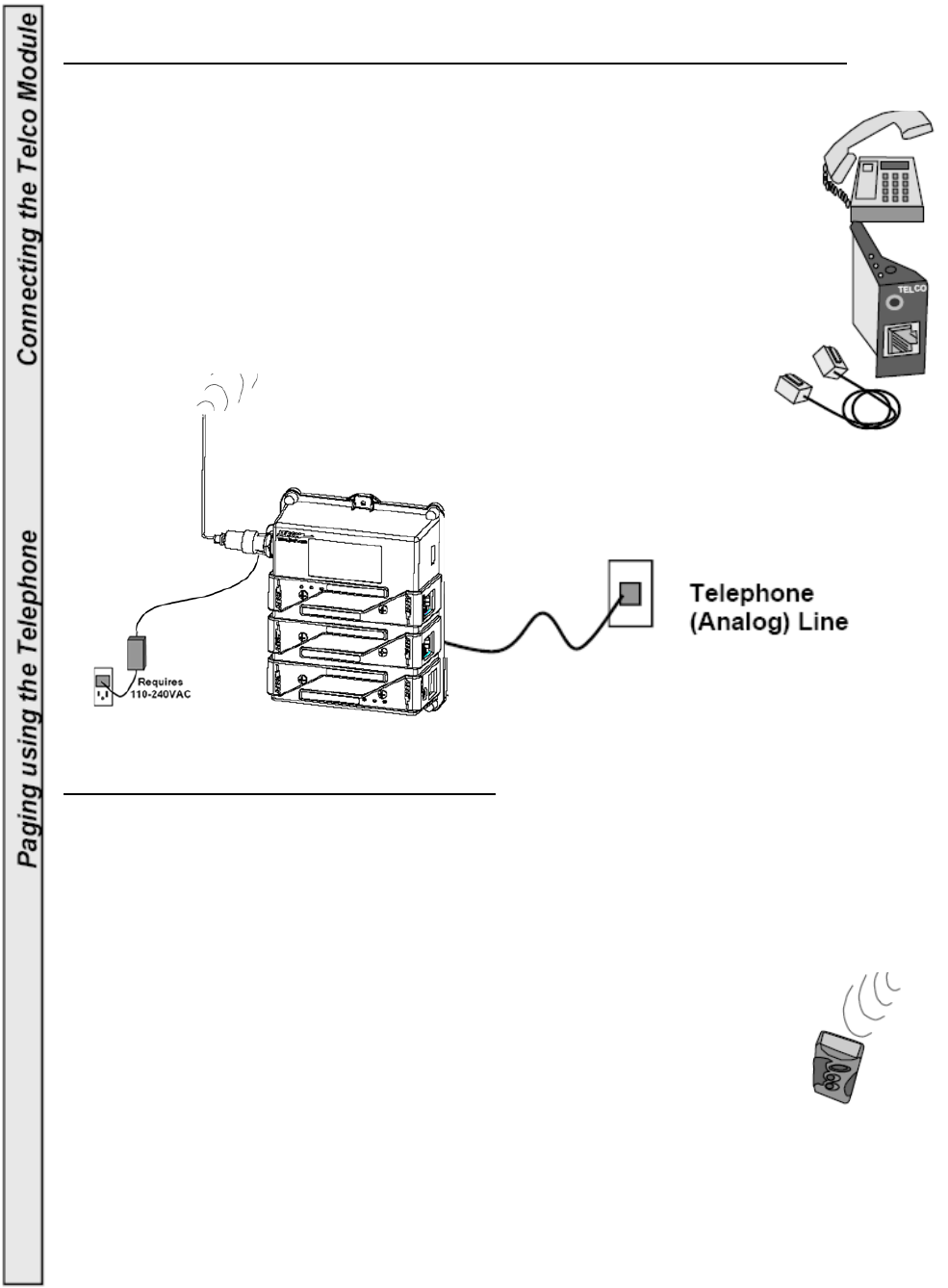
Connecting the TELCO (Telecommunications) Module for Phone connections.
1. Verify that a TELCO Module has been installed in your Controller.
The Module can be installed into any of the expansion slots except slot 6.
2. Connect the supplied RJ11 Cable to the TELCO Module and the
other end to a dedicated (analog) telephone line.
3. Up to 5 TELCO Modules can be installed to 5 different phone lines
if needed. Each one independently controlled.
Paging a single pager using the telephone:
1. Pick up the phone and listen for the dial tone.
2. Dial the phone number that has been assigned to the TELCO Module installed.
3. Listen for a voice message from the telephone that confirms the Controller is ready.
4. Within 8-10 seconds, use the telephone keypad:
a. Enter the Pager number (up to 4 digits).
b. Press the * key.
c. Enter a numeric message, if desired (16 digits maximum).
d. Press the # key to send the page.
5. A voice message heard on the phone confirms the message was sent.
6. Hang up the telephone.
13
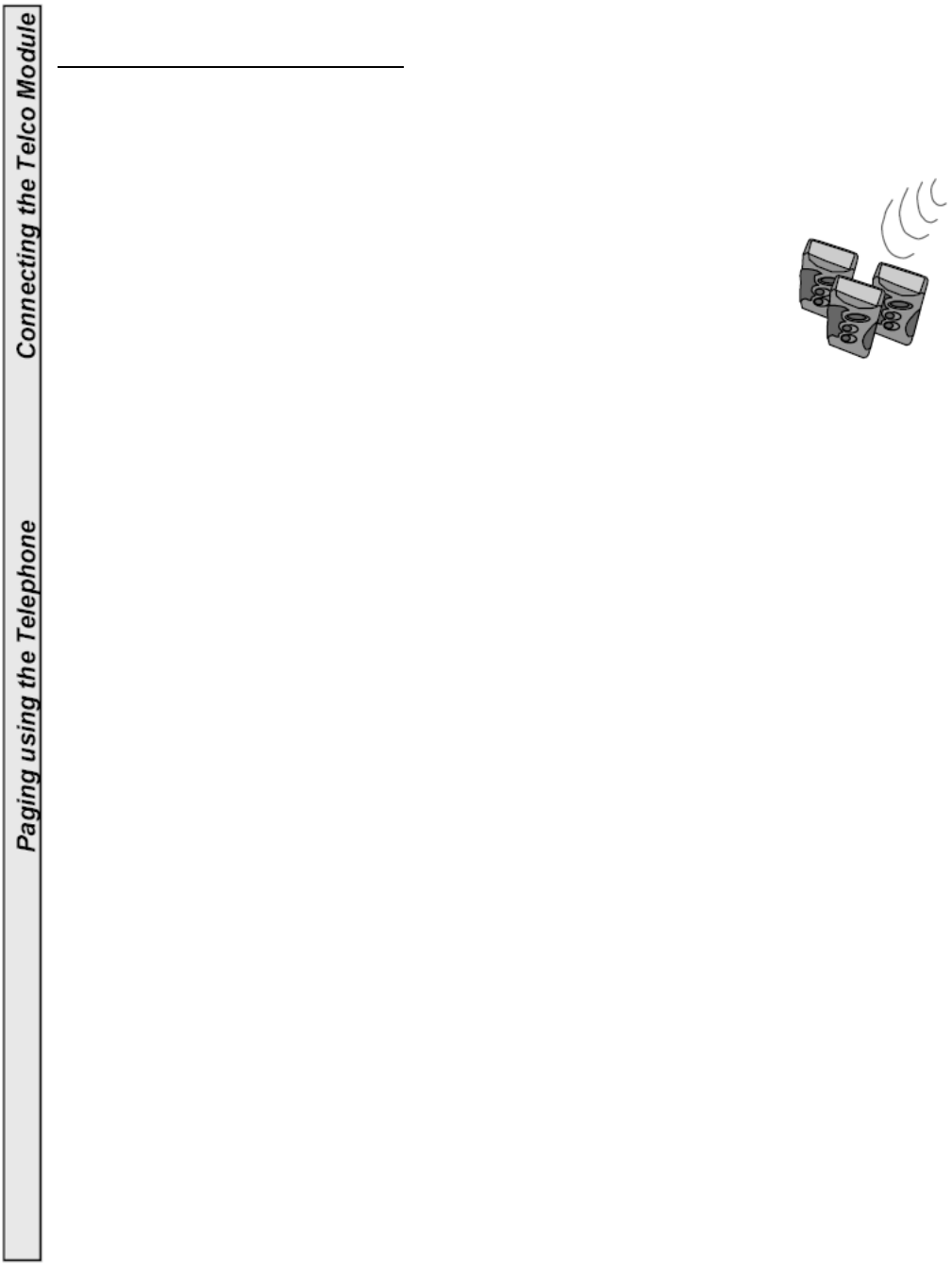
Group Paging using the telephone:
Group information can be preprogrammed into the Pagers at your Distributor’s site or
JTECH. “Dynamic” Groups can be programmed by the user.
1. Pick up the telephone and listen for the dial tone.
2. Dial the telephone number that has been assigned to the
Telco Module installed.
3. Listen for a voice message that confirms the Controller is ready.
4. Within 8-10 seconds, use the telephone keypad:
a. Press the * key.
b. Enter the Group number (1-99) to page.
c. Press the * key.
d. Enter a numeric message, if desired (16 digits maximum).
e. Press the # key to send the page.
5. A voice message heard on the phone verifies that the message was sent.
6. Hang up the telephone.
14
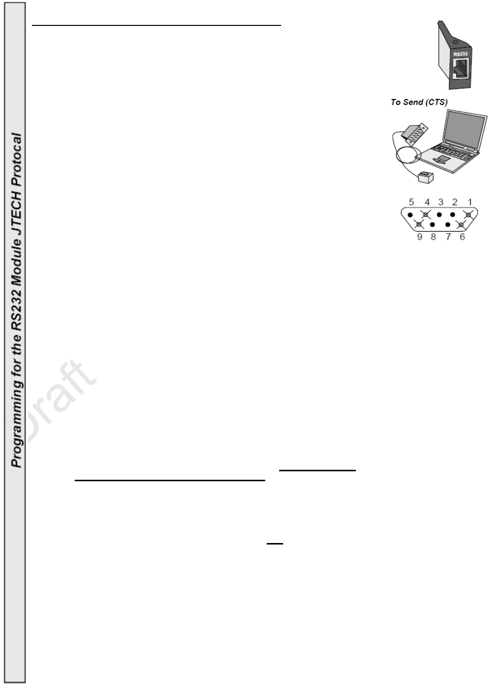
Programming For The RS232—JTECH Protocol:
To communicate with the Controller, the computer software must send
RS232 1200 baud message information using the following protocol.
RS232 Baud Rate And Settings
1200,N,8,1 (1200 Baud, No Parity, 8 Data Bits, 1 Stop Bit).
RS232 Handshaking-Request To Send (RTS) - Clear To Send (CTS)
• The Controller uses CTS to allow data out of the Host output buffer.
• The Controller does not monitor RTS.
• The Controller requires the host to stop sending data immediately,
when CTS signal switches from high to low. Incoming data are not
monitored while CTS signal is low.
• High-speed serial port drivers may continue to send data after CTS
signal is switched to low. This condition causes data to be lost.
Serial port drivers having settings for the amount of buffered data ,
should be set to 0.
7 Digit Message Format: Contains six parts:
1. Preamble (3 bytes) 4. Separator (1 byte)
2. Function Bit (1 byte) 5. Pager Message (120 bytes max.)
3. Cap Code (7 bytes) 6. Terminator (1 byte)
Preamble: Is a 3 character hex string that supplies start up synchronization
“padding” between messages IN, an output buffer, and information to the
Controller, that a message is coming. The Preamble is [Chr$(255)].
Function Bit: The Function Bit is the single hex character following the preamble.
This character tells the Controller which bit to turn ON in the POCSAG
message sent. Characters are:
(Hex 01) Non Priority Alert for Numeric Pagers.
(Hex 02) Priority Alert for Numeric Pagers.
(Hex 03) Non Priority Alert for Alphanumeric Pagers.
(Hex 04) Priority Alert for Alphanumeric Pagers.
Cap Code: Cap Code is a seven digit data string which contains the address
information of the Pager to be used.
Cap Code Prefix: Is the first 3 digits of the Cap Code. ONLY Cap Code
Prefixes of 000 and 008-199 are allowed. If the first 3 digits of the Pagers
cap code are [000], the Controller will convert the last 4 digits (Pager number)
of Cap Code by multiplying by 8.
Example: Cap code information sent to the Controller = [0000111].
The Controller sends to the Pager address [0000888].
If the first 3 digits of the Pagers cap code are not [000], the Controller will send the
Cap Code information as received.
Example: Cap code information sent to the Controller = [1230111].
The Controller sends to the Pager address [1230111].
15
Messages:
•
Alphanumeric Pagers
can be sent a maximum of 120 alpha characters
(using separator Chr$(02) orChr$(0A)).
•
Numeric Pagers can be sent a maximum of 16 numeric characters (using
separator Chr$(0B) or Chr$(03)).
•
ParentPass or Patron use message characters as controls.
•
PeoplePass ( programmed without Groups) use message characters as
controls.
Example: To send default alert three to a Glowster or CommPass, send
the hex string to the Controller: FF FF FF 01 3P 3P 3P 3P 3P
3P 3P 03 0D] where PPPPPPP is the 7 digit Pager number. See Cap
Code for more information.
Example: To send an alert, other than the default, send the hex string to the
Controller [FF FF FF 01 3P 3P 3P 3P 3P 3P 3P 03 3A 3A 0D] where
PPPPPPP is the 7 digit Pager number and AA is the alert.
Alerts AA 3A,3A Alert type
31 33, 31 Alert 1 – one alert of 15 seconds total.
32 33, 32 Alert 2 – two alerts for 30 seconds total.
33 33, 33 Alert 3 – three alerts for 45 seconds total.
34 33, 34 Alert 4 – four alerts for 60 seconds total.
35 33, 35 Alert 5 – sixty alerts for 15 minutes total.
36 33, 36 Alert 6 - Demo alert 1 for 5 seconds total.
37 33, 37 Alert 7 - Demo Alert 2 for 7 seconds total.
38 33, 38 Alert 8 - Range Test Alert.
39 33, 39 Alert 9
30 33, 30 Alert 0 - Group Alert.
The first ‘33’ in the message is used as a filler and can be any ASCII
numeric digit.
Terminator: The terminator marks the end of message. The terminator character is
the Chr$(13) or Hex 0D.
Example Of Visual Basic Code: Below is an sample section from a Visual Basic
program. This example produces a non-inverted, non-priority page sent to a 512 baud
Alphanumeric Pager.
MSComm1.PortOpen = True (Opens serial port for communication)
Preamble = Chr$(255) & Chr$(255) & Chr$(255)
FBit = Chr$(03) (Set Function bit #3 (non-priority for Alpha)) Cap
Code = “1236789” (where ‘123’ is the cap code prefix and ‘6789’ is the Pager number)
Separator = Chr$(10) (This is an Non Inverted, 512 RF baud, Alpha Page)
PagerMessage = “This is a test Page”
Terminator = Chr$(13)
OutPutString = Preamble & Fbit & CapCode & Separator & PagerMessage & Terminator
MSComm1.Output = OutPutString
Example of Hex Data Stream Into Controller:
[FF FF FF 03 31 32 33 36 37 38 39 0A 54 48 49 53 20 49 53 20 41 20 54 45 53 54 20 50 41 47 45 OD]
Example Data Stream reads as:
| P | F | Cap Code:1236789 | S| Message: THIS IS A TEST
PAGE | T |
P =Preamble
F = Function Bit
Cap Code = Seven Digits (the 3-digit cap code prefix should match the cap code prefix stored in the
Controller; the remaining 4 digits represent the Pager number)
S = Separator
Message = A maximum of 120 alphanumeric or 16 numeric characters (Function Bit
determines alphanumeric or numeric)
T = Terminator
16
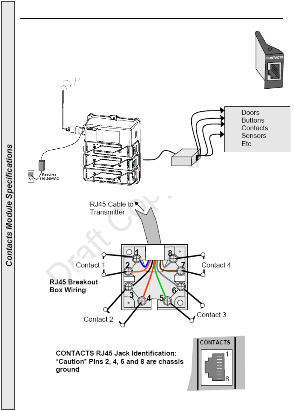
CONTACTS (Using remote contacts to send pages (CONTACTS Module Required)
1. Verify that a CONTACTS Module has been installed if needed.
The Module can be installed into any of the controllers expansion slots.
2. Up to 6 Contacts Modules can be installed if needed.
3. Each CONTACTS Module has the ability to monitor
4 individual contacts; doors, buttons, sensors, etc
17

18
FC
C
Important Note
FCC RF Exposure Statement
Under Industry Canada regulations, this radio transmitter may only operate using an
antenna of a type and maximum (or lesser) gain approved for the transmitter by
Industry Canada. To reduce potential radio interference to other users, the antenna
type and its gain should be so chosen that the equivalent isotropically radiated power
(e.i.r.p.) is not more than that necessary for successful communication.
This radio transmitter has been approved by Industry Canada to operate with the antenna types listed
below with the maximum permissible gain and required antenna impedance for each antenna type
indicated. Antenna types not included in this list, having a gain greater than the maximum gain
indicated for that type, are strictly prohibited for use with this device.
Antenna Gain: 2.0dBi max.
Antenna Type: 50ohm BNC, monopole antenna
To satisfy FCC RF exposure requirements, a separation distance of 25 cm or more should be maintained
between the antenna of this device and persons during device operation. To ensure compliance,
operations at closer than this distance is not recommended.
Conformément à la réglementation d'Industrie Canada, le présent émetteur radio peut fonctionner avec
une antenne d'un type et d'un gain maximal (ou inférieur) approuvé pour l'émetteur par Industrie
Canada. Dans le but de réduire les risques de brouillage radioélectrique à l'intention des autres
utilisateurs, il faut choisir le type d'antenne et son gain de sorte que la puissance isotrope rayonnée
équivalente (p.i.r.e.) ne dépasse pas l'intensité nécessaire à l'établissement d'une communication
satisfaisante.
Le présent émetteur radio (identifier le dispositif par son numéro de certification ou son numéro de
modèle s'il fait partie du matériel de catégorie I) a été approuvé par Industrie Canada pour fonctionner
avec les types d'antenne énumérés ci-dessous et ayant un gain admissible maximal et l'impédance
requise pour chaque type d'antenne. Les types d'antenne non inclus dans cette liste, ou dont le gain est
supérieur au gain maximal indiqué, sont strictement interdits pour l'exploitation de l'émetteur.
Gain d'antenne: 2.0dBi maximal
Type d'antenne: 50 Ω BNC, antenne monopôle
Les antennes installées doivent être situées de facon à ce que la population ne puisse y être exposée à
une distance de moin de 25 cm. Installer les antennes de facon à ce que le personnel ne puisse
approcher à 25 cm ou moins de la position centrale de l’ antenne.
La FCC des états-Unis stipule que cet appareil doit être en tout temps éloigné d’au moins 25 cm des
personnes pendant son functionnement.