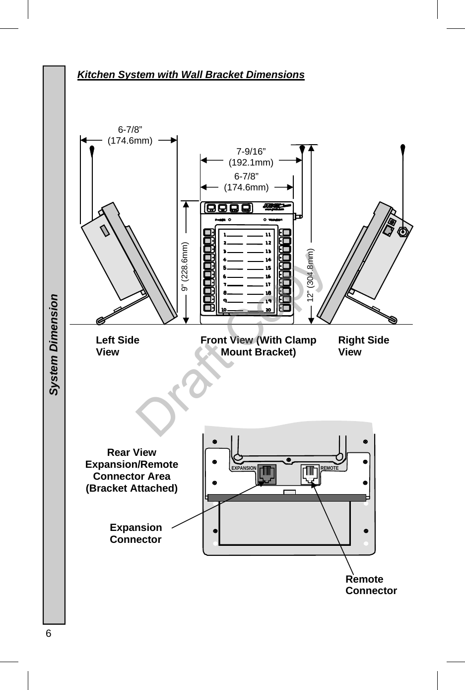
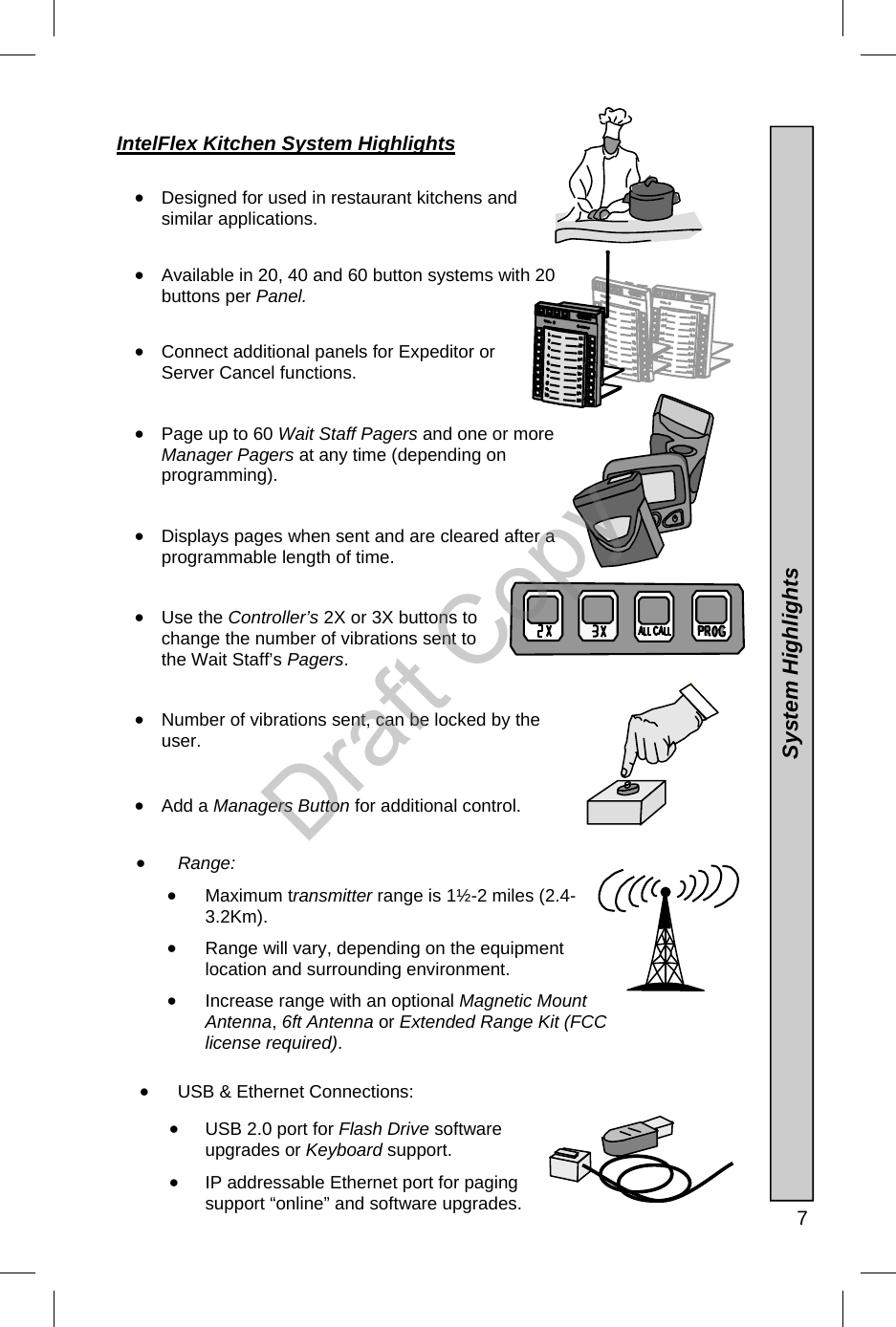
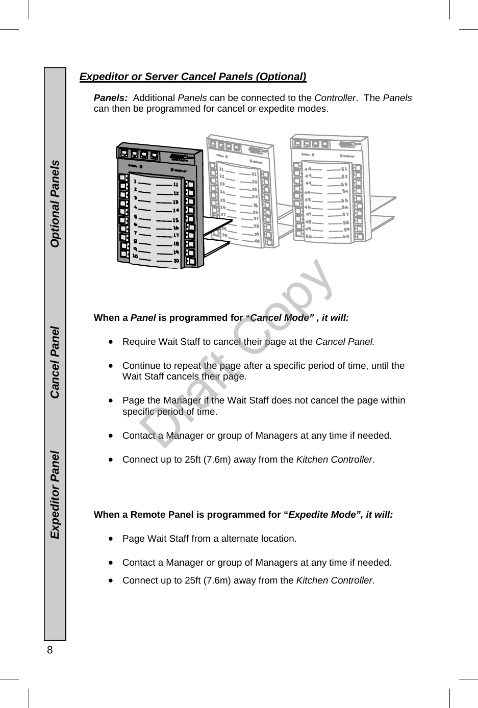
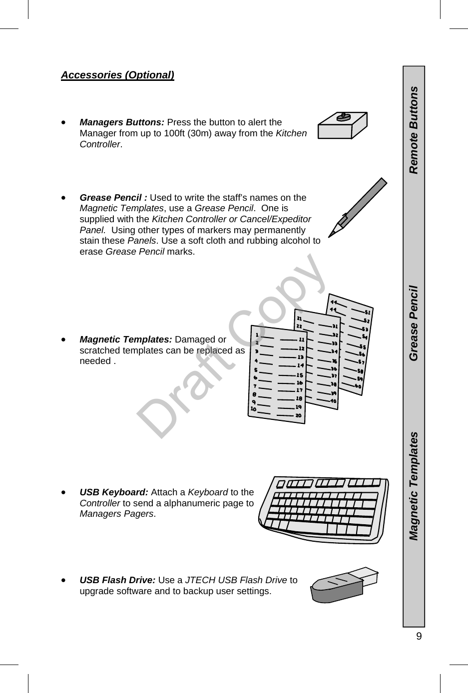
JTECH Communications INTELFLEXKP Kitchen Controller User Manual Patton ServAlert 5 2

JTECH Communications, Inc. Kitchen Controller Patton ServAlert 5 2

User Manual

     Installation, Programming and Operator Guide Part Number TBD          IntelFlex™Controller  Kitchen System                Draft Copy
 2   Introduction Congratulations on your purchase of a JTECH Kitchen Messaging System containing the IntelFlex Kitchen Controller. Please take a few minutes to review this manual prior to installing and operating your system.    Please inspect the System upon receipt.  If the contents appear to be damaged, notify the shipper immediately to file a claim and notify JTECH Customer Care. If components are missing, contact JTECH Customer Care.  If you have any questions or need assistance, please call JTECH Customer Care at 800-321-6221 or 561-997-0772, option 6.    IntelFlex  20, 40 and 60 Button Systems                 Introduction Wait Staff and Managers Pagers 6Ft, Magnetic Mount or 35W Antenna Kit  (Optional Equipment) IntelFlex Kitchen Controller ( Expansion Panels Optional ) IntelFlex  20, 40 and 60 Button Systems                 Introduction Managers Buttons (Optional)  System also work with IntelFlex Desktop Controllers Remote Panels Cancel or Expeditor Ability ( Expansion Panels Optional) Grease Pencil Requires 110-240VAC  Draft Copy
 4  Front View (With Clamp Mount Bracket)  General Specifications        DC Operating Voltage:      13.5VDC 2.4A   Power Adapter       110-240VAC 50-60Hz power adapter  Transmitter Power Output::     0.1-2 Watts  -  adjustable using 5 levels. Keypad Display:           20 Button LED Modulation:    FSK 512 BPS Protocol:  POCSAG Transmit:     512. 1200, 2400 Baud 3-3/16” (81mm) 9-5/16” (236.4mm) 1/8 - 2 1/16”  (3.2-52.4mm) Left Side 7-5/16”  (185.7mm) 11-3/8” (288.9mm) 16-5/16” (413.5mm) 1.3/16” (30.1mm) 6-7/8”  (174.6mm) 5-1/2”  (139.7mAdjustable  Threaded  Knob (6mm) Right Side Rear View  Connector Area (Brackets Attached)  REMOTE EXPANSION Kitchen System with Clamp Bracket Dimensions  System Dimension                 General Specifications Expansion Connector Remote Connector  7-9/16”  (192.1mmDraft Copy
  5 Rear View  Connector Area (Bracket Remove)  Antenna Port:   50 ohm BNC  Antenna (Standard)   6” (153mm) Rotating Whip Stainless Steel”  Operating Frequency:       UHF synthesized 450-470 MHz. (standard) Temperature Stability:       -22°to 122°F (-30 to 50°C) at better than 5 ppm Weight :  2.5-3.0 Lbs (1.14-1.36Kg) -Depending on Mounting  Brackets used. Weight: (Keypad Only)  1.85-2.35Lbs (0.84-1.1.07Kg) -Depending on Mounting   Brackets Used. 4 Mounting Slots for 1/4” (6-7mm)Diameter Screws or Bolts Rear View (With Wall Mount bracket) Left Side 1-7/16” (36.5mm) 3-9/16”  (90.5mm) 5 –11/16” (144.5mm) 3-3/8” (85.7mm) 8-1/8” (206.4mm) 6-1/2”- (165.1mm) 1-9/16” (39.7mm) Left Side EXPANSION REMOTE Kitchen System with Wall Bracket Dimensions  Expansion Connector Remote Connector  System Dimension                 General Specifications Draft Copy
 6  Rear View  Expansion/Remote Connector Area (Bracket Attached) 12” (304.8mm) 9” (228.6mm) 7-9/16”  (192.1mm) 6-7/8”  (174.6mm) Front View (With Clamp Mount Bracket) Left Side View  Right Side View 6-7/8”  (174.6mm) REMOTE EXPANSION Kitchen System with Wall Bracket Dimensions  Expansion Connector Remote Connector  System Dimension                  Draft Copy
  7 IntelFlex Kitchen System Highlights   •  Designed for used in restaurant kitchens and similar applications.   •  Available in 20, 40 and 60 button systems with 20 buttons per Panel.     •  Connect additional panels for Expeditor or Server Cancel functions.   •  Page up to 60 Wait Staff Pagers and one or more Manager Pagers at any time (depending on programming).   •  Displays pages when sent and are cleared after a programmable length of time.   •  Use the Controller’s 2X or 3X buttons to change the number of vibrations sent to the Wait Staff’s Pagers.   •  Number of vibrations sent, can be locked by the user.   •  Add a Managers Button for additional control.  •  Range: •  Maximum transmitter range is 1½-2 miles (2.4-3.2Km).  •  Range will vary, depending on the equipment location and surrounding environment. •  Increase range with an optional Magnetic Mount Antenna, 6ft Antenna or Extended Range Kit (FCC license required).  •  USB & Ethernet Connections:  •  USB 2.0 port for Flash Drive software upgrades or Keyboard support. •  IP addressable Ethernet port for paging support “online” and software upgrades.  System Highlights Draft Copy
 8  Expeditor or Server Cancel Panels (Optional)     Panels:  Additional Panels can be connected to the Controller.  The Panels can then be programmed for cancel or expedite modes.                      When a Panel is programmed for “Cancel Mode” , it will:    •  Require Wait Staff to cancel their page at the Cancel Panel.  •  Continue to repeat the page after a specific period of time, until the Wait Staff cancels their page.  •  Page the Manager if the Wait Staff does not cancel the page within specific period of time.  •  Contact a Manager or group of Managers at any time if needed.  •  Connect up to 25ft (7.6m) away from the Kitchen Controller.       When a Remote Panel is programmed for “Expedite Mode”, it will:   •  Page Wait Staff from a alternate location.  •  Contact a Manager or group of Managers at any time if needed.  •  Connect up to 25ft (7.6m) away from the Kitchen Controller.                                      Expeditor Panel                Cancel Panel                        Optional Panels Draft Copy
  9                           Magnetic Templates                      Grease Pencil                                   Remote Buttons Accessories (Optional)    •  Managers Buttons: Press the button to alert the Manager from up to 100ft (30m) away from the Kitchen Controller.      •  Grease Pencil : Used to write the staff’s names on the Magnetic Templates, use a Grease Pencil.  One is supplied with the Kitchen Controller or Cancel/Expeditor Panel.  Using other types of markers may permanently stain these Panels. Use a soft cloth and rubbing alcohol to erase Grease Pencil marks.          •  Magnetic Templates: Damaged or scratched templates can be replaced as needed .            •  USB Keyboard: Attach a Keyboard to the Controller to send a alphanumeric page to Managers Pagers.      •  USB Flash Drive: Use a JTECH USB Flash Drive to upgrade software and to backup user settings.    Draft Copy
 10      Extended Range Antenna Kit                   6’ (1.8m) Antenna                             Magnetic Mount Antenna Antenna Choices to Extend Range    All Extended Range Antenna choices require FCC approval and licensing.  JTECH can assist in acquiring any additional licensing.       •  Magnetic Mount Antenna with 12ft (3.6m) Cable: All metal indoor/outdoor Antenna with a magnetized base for mounting to steel or iron.  Wall mounting hardware include for wall mounting to non magnetic surfaces.           •  6ft (1.8m) Antenna and 25ft (7.6m) Cable:  Fiberglass indoor/outdoor Antenna which can mount to any stable surface.  Wall mounting hardware included.                      •  Extended Range Antenna Kit:  Includes a 6ft (1.8m) fiberglass indoor/outdoor Antenna, 35watt Power Amplifier, Power Supply and 50ft (15m) or 100ft (30m)Cable.  Increase the output of the Controller to 35 Watts and range of up to 5 miles (8km).   Requires 110-120VAC outlet and indoor mounting of the amplifier.  Draft Copy
  11 Pagers That Work with the IntelFlex Kitchen Controller    •  Use Vibe or Vibe/Tone Rechargeable Pagers (Wait Staff) to receive a page from the Kitchen Controller or Expeditor Panel.       •  Use Numeric (Managers) Pagers to receive numeric information from the Kitchen Controller, Cancel/Expeditor Panel or Managers Button .       •  Use Alphanumeric (Managers) Pagers to received numeric information from the Kitchen Controller, Cancel Panel, Expeditor Panel or Managers Button.  Adding a Keyboard to your Kitchen Controller allows the user to send alphanumeric messages.    •  Numeric and Alphanumeric (Managers) Pagers can be added at any time.    •  Pages can also be sent from a IntelFlex Desktop Controller (optional) to Wait Staff and Managers Pagers.  Send Numeric information to Numeric and Alphanumeric (Managers) Pagers as well.                       Guest Transmitter Paging             Alphanumeric Pagers       Numeric Pagers         Vibe/Tone Pagers Draft Copy
 12  Installing the Kitchen Controller and Cancel/Expeditor Panel     •  Mount on a wall, clamp to a shelf or let it sit on any flat surface.    •  Mount as high as possible from the floor with the antenna tip at least 18” away from any metal.  This includes; counters, backsplash, etc.    •  Walls, pipes, ducts, mirrored glass, etc. may weaken or misdirect transmitted signals.    •  Locate away from liquids or extreme heat.       •  The Antenna must be mounted vertically.    •  Mounting hardware is user supplied.  Select hardware that will ensure a safe installation.      •  Requires a 110-240 VAC 50-60Hz outlet for power.      •  Warning - All connection cables (if required) and Antenna must be connected before applying power.          Installing the Transmitter and Cancel/Expeditor Panels  Draft Copy
  13 Assembly for Clamp Brackets Shelf, Table or Counter Top Mounting                 Assembly for Stand Bracket Shelf, Table or Counter Top               Assembly for Wall Bracket Walls or Vertical Surface                    Wall mounting screws are not supplied.  Select wall mounting hardware as needed.     Wall  Bracket                       Stand Bracket                     Clamp Brackets  Draft Copy
 14  EXPANSION REMOTE Powering the Kitchen Controller  1. Connect the Power Adapter to the Kitchen Controller and plug it into a 120VAC outlet. 2. The Controller LED’s will light in a sequence, TRANSMIT light will light and the POWER light will flash.   3.  After several seconds, the TRANSMIT light turns off and the Kitchen Controller is ready for use. 4.  The POWER light continues to blink while the system is powered.                  Connecting the Cancel or Expeditor Panel  1. The Cancel/Expeditor Panel must be connected to the Kitchen Controller Panel  before connecting power. 2.  Connect the Cancel/Expeditor Panel to the Kitchen Controller Panel using the 25’ (7.6m) the RJ12 Phone Cord supplied. 3.  Connect the cable from the gray “REMOTE” jack of the Controller Panel to the gray “REMOTE” jack of the Cancel/Expeditor Panel. 4.  Connect Power to the Kitchen Controller Panel.  Antenna  12VDC Power Adapter AC  Outlet 110-240VAC Right Side View           Connecting the Cancel or Expeditor Panel                                       Powering the Transmitter Cancel/Expeditor  Panel With  Buttons 1-20 Kitchen Controller  Panel with  Buttons 1-20 Draft Copy
  15 Connecting the Cancel or Expeditor Panel with Managers Button  1. The Cancel/Expeditor Panel must be connected to the Kitchen Controller Panel  before connecting power. 2. Connect the Cancel/Expeditor Panel to the Kitchen Controller Panel using the 25’ (7.6m) the RJ12 Phone Cord supplied. 3. Plug the Phone Cord into the gray “REMOTE” jack of the Controller Panel and into the gray “REMOTE” jack of the Cancel/Expeditor Panel. 4.  Plug 1 end of the RJ-12 100’ (30m) Cable into the Kitchen Controller Panel “EXPANSION” jack and the other end into the Managers Button. •  Do not use the Managers Button as a power source.  Attempt to do so will damage the Controller •  When the Button is pressed, the Controller sends a “00” message to the Manager Pagers.               Kitchen Controller Buttons 1-20 Cancel/Expeditor Panel Buttons 1-20 Managers  Button    Connecting a 20 Button System with Cancel/Expeditor Panel All Expansion Panels connect together using the supplied 1’ (0.3m)Cables. Draft Copy
 16  Connecting a 40 Button System with Cancel/Expeditor Panels Connecting a 40 Button System with Cancel/Expeditor Panels Kitchen Controller Buttons 1-20 All Expansion Panels connect together using the supplied 1’ (0.3m)Cables. Managers  Button 1 Cancel/Expeditor Panel Buttons 1-20 Cancel/Expeditor Panel Buttons 21-40 Managers  Button 2 Expansion Panel Buttons 21-40 Draft Copy
  17     Connecting a 60 Button System with Cancel/Expeditor Panels Connecting a 60 Button System with Cancel/Expeditor Panels Kitchen Controller Buttons 1-20 Expansion Panel Buttons 21-40 Cancel/Expeditor Panel Buttons 1-20  Cancel/Expeditor Panel Buttons 21-40 Cancel/Expeditor Panel Buttons 41-60  Managers  Button 2 Managers  Button 1 Expansion Panel Buttons 41-60 All Expansion Panels connect together using the supplied 1’ (0.3m)Cables. Draft Copy
 18  Range Testing    When the Controller is put into Range Test Mode, it will continue to send a page every 3-4 seconds for 4 minutes.  This will allow a person to walk the area where your Pagers will be used and check for dead spots or weak signal areas.  If you find such areas, try relocating the Controller.             To set the Controller into Range Test Mode  1. Wear any Wait Staff Pager as usual, do not hold the Pager in your hands.   2. The Pager selected will vibrate during the range test. 3.  Press and hold the program button for 2 seconds.   4.  LED’s 1-7 will light up. 5.  Press button 6.  6.  All LED’s and TRANSMIT will blink. 7.  Press the button, for the Pager you are using.  8.  The LED for that button will turn on, all other buttons will blink. 9. TRANSMIT button will blink every 3-4 seconds. 10.  Move around the paging area, the Pager worn will continue to alert every 2-4 seconds while in the range of the Controller.  Range Testing Draft Copy
  19 Paging using a Controller or Expeditor Panel  1.  Press the number on the Controller or Expeditor Panel of the Pager you want to page. 2.  The light on the Panel, next to that number will turn ON.   3.  The TRANSMIT light will turn ON for 2-3 seconds and turn off. 4. The Pager will receive a single, one second vibration (factory setting) or: A.    Send double or triple vibrations individually at any time by pressing 2X or 3X button before pressing the Pager button. The Controller must be programmed for single vibration (factory setting) for these buttons to work as described.   B.    Send double or triple vibrations by changing the Controller settings. If changed, it affects all Pagers used and the 2X and 3X buttons are disabled.   5.  The light on the panel, next to that Pager number, will continue to stay ON for 40 seconds (factory setting). 6. If a Controller and Expeditor Panel are combined, pressing a button on either panel will light both panels. 7.  After 40 seconds (factory setting), the light next to the number pressed will begin to blink on the Panel or Panels for an additional 40 seconds (factory setting), before turning off.        Paging the Managers Pager  1. Page the Managers Pager at any time by pressing PROG on the Controller or  Expeditor/Cancel Panel. 2.  The TRANSMIT light will turn ON for 2-3 seconds and turn off. 3.  If paged from a Controller, the Managers Pager will display “99”. 4.  If paged from a Expeditor Panel, the Managers Pager will display “98”. 5.  If paged from a Managers Button, the Managers Pager will display “00”.  Paging a Managers Pager                         Paging a Transmitter or Expeditor Panel Draft Copy
 20  Using the Cancel Panel •  The Cancel Panel is used to cancel (end) pages sent from the Controller.   •  After the Controller sends a page, the Wait Staff must cancel (end) the page by pressing the Pager number button on the Cancel Panel.    •  If not canceled, the Controller will continue to page the Pager.   •  The delay between repeat pages is 40 seconds (factory setting) and can be adjusted by changing the program settings. •  When a page is sent; 1. The Pager number on the Controller and the Cancel Panel will light for 40 seconds (factory setting).   2.  If the page is not canceled within 40 seconds, the panel light will blink and send a 2nd page to the Pager. 3.  If the page is not canceled within 40 seconds, the Controller will send a 3rd page and send a single vibration and Pager number message to the Managers Pagers.    4.  If the page is not canceled within 40 seconds, The Controller repeats a page to the Wait Staff Pager and Managers Pager every 40 seconds until the page has been canceled.   Using a Managers Button   •  The Managers Button can be connected to a Controller for paging the Manager from an alternate location.          •  Managers Button when press, sends a “00” page to the Managers Pagers.                                  Using the Managers  Button                           Using the Cancel Panel Draft Copy
  21 Paging from a IntelFlex Desktop Controller    If you also have a IntelFlex Desktop Controller set to the same Frequency and Cap Code Prefix (see IntelFlex Desktop Controller manual), you can page your Wait Staff, Manager or group of Mangers from it.                 Page Wait Staff from a IntelFlex Desktop Controller  1. From the Desktop Controller press “90NN” where NN = the Wait Staff Pager number. 2.  Press # or “SEND”. 3. That Pager will receive a alert of 16 short vibrations.        Page the Manager from a Desktop Controller  1. Page the Managers Pager by pressing “9NNN”, where NNN = Managers Pager number.  2.  Add a message by pressing * and enter up to a 16 digit numeric message, if desired. 3.  Press # or “SEND” 4.  Also can send “Canned” Alphanumeric messages from the Keypad or using the optional USB Keyboard.  See the IntelFlex Desktop System manual for more information.    Paging From a Desktop Controller Draft Copy
 22  Standard Program Settings  Factory Settings: Unless ordered otherwise, the factory defaults are: •  Pick Up Period:           =   40 seconds  •  All Call:             =   Selected •  Remote Panel Setting   =   Expedite mode  •  Number Of Vibrations    =   Single Vibration •  Transmit Power          =   2 Watt (Maximum)    Pick Up Time  Factory setting is 40 seconds.  To program:  1.  Press and hold the PROG on the Controller Panel for 2 seconds. 2.  LED’s 1-7 will blink. 3.  Press button 3. 4.  The current setting will blink and the remaining LED’s will light. Each button = its value X 10 seconds.  For example, button 5= 50 seconds. 5.  Set for 10-80 seconds by pressing buttons 1-8 as needed. 6.  To return to the programming mode, press ALL CALL once.   7.  To return to normal operation, press ALL CALL again.    ALL CALL  When the ALL CALL button is pressed the Controller will page all Pagers.  The alert will be 4 short double  vibrations and then a short single vibration. To program:  1.  Press and hold PROG button on the Controller Panel for 2 seconds . 2.  LED’s 1-7 will blink. 3.  Press button 4. 4.  A blinking LED indicates the current choice.   Button blinking 1 = ALL CALL ON   Button blinking 2 = ALL CALL OFF 5.  Press button 1 to turn ALL CALL ON or button 2 to turn ALL CALL OFF. 6.  Press ALL CALL once to return to programming mode. 7.  Press ALL CALL again to return to normal operation.                                All Call                                                  Pick Up Time                     Factory Settings  Draft Copy
  23 Cancel/Expedite Mode  The Panel can be programmed as a Cancel  or Expeditor Panel and cannot be both at the same time.  A Cancel Panel is used by the Wait Staff to cancel their pages after picking up an order.  A Expeditor Panel is used by an Assistant or Chef to page the Wait Staff. To program:  1.  Press and hold PROG on the Controller for 2 seconds. 2.  LED’s 1-7 will be ON. 3.  Press button 1. 4.  LED’s 1-2 will light with the current choice blinking;        1= Cancel, 2=Expedite.   5.  Press button 1 (Cancel) or 2 (Expedite) as needed. 6.  Press ALL CALL to return to programming mode. 7.  Press ALL CALL again to exit programming mode.  Number of vibrations    The number of vibrations sent from the Controller, Cancel/Expeditor Panels to the Pagers can be locked by the user.  If locked, it will always send the same number of vibrations to the Pagers.  This can be used to identify which panel (Controller, Cancel or Expeditor) sends the page. Each Panel can be set for a specific number of vibrations.  Factory setting is 1 vibration. If set to 2 or 3 vibrations, the X2 or X3 buttons on the Panel are disabled. To program:  1.  Press and hold PROG on the Controller Panel for 2 seconds. 2.  LED’s 1-7 will blink. 3.  Press button 2. 4.  LED’s 1-3 and 6-8 will light with the current choice blinking.   5.  Press button 1, 2 or 3 to select the number of vibrations for the Controller. 6.  Press 6, 7 or 8 for the number of vibrations for the Cancel/Expeditor Panel.  Pressing 6=1, 7=2, 8=3 vibrations.  7.  To return to programming mode press ALL CALL. 8.  To exit programming mode, press ALL CALL again.  Transmit Power    Power can be adjusted as needed.  The Controller is set at the maximum 2.0 Watts at the factory. To adjust:  1.  Press and hold PROG on the Controller Panel for 2 seconds. 2.  Led’s 1-7 will blink. 3.  Press button 7. 4.  LED’s 1-5 will light with the current choice blinking.        1=0.1Watts   2=0.4Watts   3=0.82Watts   4=1.4Watts   5=2.0Watts  5.  Press button 1-5 to select the transmit power of the Controller. 6.  To exit programming mode, press ALL CALL.                  Transmit Power                      Number Of Vibrations                   Cancel/Expedite Mode Draft Copy
 24  Service     Assistance  For assistance, please contact JTECH Customer Care at 800-321-6221, fax at 561-995-2260 or email at wecare@jtech.com . JTECH provides complete diagnostic technical support 24 hours a day, 7 days a week.     Warranty  Equipment under warranty will be repaired  without charge.   Extended warranties are available. If the equipment is out of warranty, there will be a nominal service fee charged when the equipment has been repaired and shipped.       Billing for Repairs  Terms are C.O.D. (company check), company billing or credit card.  If “advanced replacement” is required, replacement equipment will arrive with a packing list and a Return Material Authorization Sheet (RMA).  To return the defective equipment and ensure proper credit,  include the Return Material Authorization (RMA) sheet in the shipment back to JTECH.  Mark the outside of the box with the Return Material Authorization (RMA) number.  If advance replacement of equipment service is used and the defective equipment is not received back at JTECH within 10 days, JTECH will bill the amount of the list price of the equipment to the Customer.       Shipping Costs  Costs to ship equipment from JTECH to the Customer paid by JTECH.  If Expedited shipping is needed, the Customer pays the additional costs.  Costs for shipping equipment from the Customer to JTECH are the responsibility of the Customer.  JTECH recommends using a shipping service that is traceable in case shipping delays occur.                   Service Draft Copy
  25 General Terms and Conditions  This offer is subject to the terms and conditions listed below which are binding upon the seller and the buyer under this offer and are hereby incorporated by reference in any subsequent agreement for purchase duly executed between JTECH Communications Inc. (Seller) and its buyer of goods proposed for sale herein: 1.  Price.  All prices are F.O.B. point of origin, unless otherwise agreed to in writing by the buyer and seller.  Prices quoted are those in effect at the time of quotation and are valid for 30 days from the date of quotation regardless of existence of any written confirmation.  Until the proposal price and subsequent purchase price are paid in full, the buyer grants seller a security interest in all of the goods described in this proposal all of the goods described in any resulting contract and buyer agrees to sign on seller's request any required documentation to complete seller's said security interest. 2.  Payment Terms.  Normal payment terms are C.O.D. unless otherwise set forth in this proposal.  Any outstanding balances not paid by the date on which they are due to JTECH Communications Inc. Inc. shall be subject to interest of 1 1/2% per month on the unpaid balance (or the maximum allowable by law whichever is the lesser) as well as rebilling charges together with reasonable attorney's fees and paralegal fees including all such fees in any appeal together with all costs associated with efforts by JTECH Communications Inc. to enforce the terms of this proposal as well as all agreements between the parties.  Any discounts offered will be calculated from the date of invoice to the date that payment is received by JTECH Communications Inc. or JTECH Communications Inc.'s agents.  Any discount is void if not taken at time of payment of the invoice containing said discount within thirty (30) days of the date on which the goods for which the discount is allowed, have been received by Buyer, its agents or employees.   3.  Products.  Products are defined as those items listed on this proposal and a subsequent resultant purchase order to JTECH Communications Inc. containing items listed on this proposal. 4.  Acceptance.  Upon receipt the buyer shall immediately inspect and/or test the products.  Unless stated otherwise in writing on the final agreement between the parties, products shall be deemed accepted unless the buyer notifies JTECH Communications Inc. within 5 working days after receipt of shipment of any defect or discrepancy. 5. Transportation.  Unless the buyer specifies the method of transportation, JTECH Communications Inc. will use its best judgment in determining the method of transportation.  All costs of standard transportation, premium transportation if required through no fault of JTECH, and other costs such as excise taxes, duty, freight forwarding or the like shall be billed to the buyer. 6. Title and Risk of Loss.  Title of goods sold, shall pass to buyer at the F.O.B. point. 7.  Limited Warranty for material and workmanship.    JTECH (Seller) warrants to the buyer that products purchased from JTECH shall be free from defects in material and workmanship under normal use and service.  JTECH's obligation under this warranty shall be limited to the repair or exchange of any part or parts which may thus prove defective under normal use and service within one (1) year from date of purchase by the original purchaser, and which our examination shall disclose to our satisfaction to be thus defective. THIS PROPOSAL AND SUBSEQUENT SALE ARE MADE ON THE EXPRESS UNDERSTANDING THAT THERE IS NO IMPLIED WARRANTY THAT THE GOODS SHALL BE MERCHANTABLE NOR AN IMPLIED WARRANTY THAT THE GOODS SHALL BE FIT FOR ANY PARTICULAR PURPOSE.  THE BUYER ACKNOWLEDGES THAT BUYER IS NOT RELYING ON THE SELLER'S SKILL OR JUDGMENT TO SELECT OR FURNISH GOODS SUITABLE FOR ANY PARTICULAR PURPOSE AND THAT THERE ARE NO WARRANTIES WHICH EXTEND BEYOND THOSE PREVIOUSLY SET FORTH HEREIN.    PURCHASER IS DIRECTED NOT TO RELY ON JTECH'S PRODUCTS TO FUNCTION AS AN INTEGRAL PART OF ITS LIFE CARE/LIFE SUPPORT PROCEDURES OR SYSTEMS.  JTECH'S PRODUCTS ARE NOT DESIGNED FOR SUCH USE; PARTICULARLY WHEN AN ALLEGATION MAY BE MADE THAT PRODUCT MALFUNCTION CONTRIBUTED TO THE FAILURE TO ADMINISTER A PROPER TREATMENT, PROCEDURE, ACTION OR MEDICATION. BUYER AGREES TO FULLY PROTECT, DEFEND AND HOLD SELLER HARMLESS FROM CLAIMS OR DAMAGES RESULTING FROM THE USE OF JTECH'S PRODUCTS IN LIFE CARE/LIFE SUPPORT PROCEDURES.  Any claim by the buyer for the repair or exchange of goods proposed and of goods actually sold to buyer shall be deemed waived by the buyer unless submitted in writing to JTECH within the earlier of (a) 30 (thirty) days from the date the buyer discovered or by reasonable inspection should have discovered any claimed breach of the foregoing warranty.   8.  Damages Based Upon Negligence or Strict Liability.  JTECH's obligation based upon any claim of negligence or of strict liability as a result of its delivery of products ordered by Buyer, shall be limited to, at JTECH's option, repairing or replacing the products that are found by JTECH to be defective, or refunding the purchase price of such products.  In no event shall JTECH's liability exceed the purchase price of the products that are subject matter of any such claim.  JTECH shall not be obligated to make any such refund or replacement until at least thirty(30) days after JTECH has received from Buyer the subject alleged defective product, which will be shipped to JTECH at the buyer's expense. 9. Disclaimer of Consequential Damages.  In no event shall JTECH be liable for incidental or consequential damages arising out of or in connection with the purchase by Buyer of goods from JTECH including, without limitation, such damages that may be caused by a breach of any obligation or warranty imposed on JTECH under such purchase.  Consequential damages shall include without limitation, loss of use, income or profit, or loss sustained as the result of injury to any person, or loss or damage to any property, or loss or damages sustained as the result of work stoppage.  Buyer shall indemnify JTECH against all liability, cost or expense that may be sustained by JTECH due to loss, damage or injury.  IN NO EVENT, SHALL JTECH'S LIABILITY EXCEED THE PURCHASE PRICE OF GOODS.  10. Taxes. Unless specifically provided herein, the price for goods purchased as a result of this proposal does not include sales, use, excise or similar taxes, whether Federal, State or local.  Buyer is responsible for all applicable taxes for any goods after title passes to the Buyer at the F.O.B. point.  If Buyer is exempt from paying sales taxes, a certificate evidencing such shall be provided to JTECH upon request. 11. Export.  Buyer agrees not to directly or indirectly export any Goods purchased from JTECH (whether or not modified by subsequent services) including, but not limited to parts, equipment, software or technical data/documentation without first obtaining the required U.S. Government export license(s).  If Buyer intends to export Goods outside the U.S., Buyer shall determine whether an export license is required; and, if so, obtain that license from the U.S. Government.  Buyer shall protect, defend and indemnify JTECH from any loss or liability due to Buyer's failure to comply with export regulations.  Buyer furthers warrants that the Goods sold to Buyer from JTECH will not be resold, transferred, exported or reused in any way by Buyer in violation of any laws, General Terms and Conditions Draft Copy
 26  General Terms and Conditions regulations or export control imposed by the U. S. Government. 12. Delays. Unless specified in writing by JTECH to the contrary, goods in stock shall be shipped immediately upon the signing of a binding purchase agreement.  Goods not in stock will be shipped as soon as possible.  JTECH will not be liable for any nonperformance of the Agreement resulting from this proposal caused by strikes, fires, disasters, riots, acts of God or other causes or conditions beyond JTECH's reasonable control.  In the event of such delay or nonperformance, JTECH may, at its sole option, and without liability, cancel any portion of the Agreement resulting from this proposal and/or extend any date upon which any performance is due. 13. Termination. If Buyer (a) fails to pay any amount owed when due, or (b) assigns or transfers the Agreement subsequently resulting from this proposal without JTECH's prior written consent, or (c) makes an assignment for benefit of creditors, or (d) files or has filed against it, petition for relief under federal or state bankruptcy laws, or (e) breaches any other term or condition of this proposal or resultant contract, JTECH may terminate any portion of the agreement resulting from this proposal in addition to JTECH's other available remedies.  If JTECH fails to perform any obligation when due, and if such failure is not remedied within thirty (30) days after receipt of written notice from Buyer, Buyer may terminate any portion of such Agreement.  In all other cases, the Agreement resulting from this proposal may be terminated by either party by giving sixty (60) days written notice.  Termination of the Agreement, for any reason, shall in no way interfere with the obligation of Buyer to pay all monies payable as of the effective date of termination or which become payable for Goods ordered and delivered after such termination.  If such Agreement is terminated by Buyer for any reason other than default by JTECH, Buyer shall be liable immediately thereupon, to pay to JTECH the full contract price for all goods completed by JTECH pursuant to the Agreement and for all work in process at the time of termination. 14. Returns and Cancellations.  Buyer may not cancel any order or return any Goods that have been special or custom ordered, custom manufactured or configured, unless specifically agreed to in writing to seller in this proposal and in the subsequent agreement.  Returns are subject to a restocking fee that will be due to seller when the goods are received by seller. 15. Patents and Copyrights. In no event shall JTECH be liable for damages arising from infringement of patents or copyrights.  In the event that Buyer should be enjoined in any such suit alleging infringement of patent(s) or copyright(s) or proceeding from using any of the Goods purchased pursuant to this proposal and subsequent Agreement, JTECH, at its option, shall either (a) secure termination of the injunction and procure for Buyer the right to use such goods without obligation or liability or (b) replace or modify said Goods with non infringing materials at JTECH's expense and refund the purchase price of the infringing goods to Buyer; provided, however, that in no event shall JTECH be liable for or have any obligations under this paragraph if the alleged infringement is by reason of the specifications provided by Buyer to JTECH under this agreement.  The foregoing shall be Buyer's exclusive remedy against JTECH with respect to any alleged patent or Copyright infringement.  The sale of goods does not convey any license of copyright under any proprietary or patent rights of any manufacturer.  JTECH shall not have any liability if the alleged infringement is based upon the use or application of the Goods in combination with other Goods and Buyer shall protect, defend, and indemnify JTECH therefrom.  JTECH disclaims all other liability for infringement of intellectual property rights and further disclaims any liability for incidental or consequential damages arising in connection with such infringement. 16. Manufacturer Liability.    In addition to JTECH's limited warranty for materials and workmanship as per section 7 herein, and unless specifically greed to in writing by the manufacturer, JTECH and Buyer, Buyer represents to JTECH and the manufacturer that the Goods sold pursuant to this proposal and the subsequent resultant Agreement incorporating such of the terms of this proposal agreed to by JTECH and buyer do not constitute standard components intended for use by Buyer or JTECH in life support systems, surgical implantation, nuclear facilities, or for any other application in which the failure of the Goods or the product in which the Goods are to be used could create a situation where personal injury or death may occur. 17. Credit Terms.  All orders and shipments shall at all times be subject to the approval of JTECH's credit department.  JTECH reserves the right of declining to make any shipment called for by the contract between seller and buyer whenever, for any reason, there is doubt in JTECH's sole judgment, as to buyer's willingness or ability to pay for the goods ordered on Buyer's solvency and JTECH shall not, in such event, be liable for breach or nonperformance of this Agreement in whole or in part. 18. Packaging.  Packaging will be standard commercial package and acceptable to commercial carriers.  Special customer packaging will be furnished only when specified and so stated herein and the cost thereof shall have been agreed to by both the Buyer and JTECH in writing. 19. Substituted or Repaired Goods.  If substitute additional or repaired goods are purchased by Buyer from JTECH, the terms and conditions of this proposal and resultant Agreement shall be applicable thereto, the same as if such substituted, additional or repaired Goods had been originally purchased hereunder unless specifically stated to the contrary in this proposal or subsequent resultant Agreement. 20. General Conditions.  No agent, salesman or other party is authorized to bind JTECH to any agreement, warranty, statement, promise or understanding not expressed herein.  The sale of Goods pursuant to this proposal and any subsequent resultant Agreement shall be governed by the laws of the State of Florida.  Any notice that is required under the terms of a resultant Agreement shall be in writing and delivered to the address of the party set forth in the Agreement and shall be effective when actually received.  The remedies reserved by the parties shall be cumulative and in addition to other remedies provided by law.  JTECH shall not be required to proceed with the performance of any obligation under a resultant Agreement so long as Buyer is in default or in breach of any of Buyer's obligations or agreements herein.  Any clerical errors are subject to correction.  No delay or omission by JTECH in exercising any right or remedy under that agreement shall constitute a waiver of such right or remedy.  The waiver, invalidity or unenforceability of any provision in a resultant Agreement shall not affect the validity of the agreement as a whole or any other provisions herein.  An Agreement resulting from this proposal shall be binding upon and shall inure to the benefit of the successors and assigns of Buyer and JTECH.  Buyer may not assign or transfer such Agreement in whole or in part without the prior written consent of JTECH.  For the purposes of such agreement, the Buyer and JTECH agree, notwithstanding any of the items sold not constituting "goods" as defined in Article 2 of the Uniform Commercial Code as enacted and amended from time to time in the state of Florida, for the purpose of interpreting this proposal or a resultant Agreement all items shall be deemed to be such "goods."  Buyer agrees that acceptance of this proposal and receipt of shipment from JTECH pursuant to any resultant Agreement shall constitute acceptance in total of the preceding General Terms and Conditions except as otherwise agree to in writing by the parties thereto. Draft Copy
 FCC   Important   Note FCC RF Exposure Statement    Under Industry Canada regulations, this radio transmitter may only operate using an  antenna of a type and maximum (or lesser) gain approved for the transmitter by  Industry Canada. To reduce potential radio interference to other users, the antenna  type and its gain should be so chosen that the equivalent isotropically radiated power  (e.i.r.p.) is not more than that necessary for successful communication.   This radio transmitter has been approved by Industry Canada to operate with the antenna types listed below with the maximum permissible gain and required antenna impedance for each antenna type indicated. Antenna types not included in this list, having a gain greater than the maximum gain indicated for that type, are strictly prohibited for use with this device.  Antenna Gain: 2.0dBi max.  Antenna Type: 50ohm BNC, monopole antenna  To satisfy FCC RF exposure requirements, a separation distance of 25 cm or more should be maintained between the antenna of this device and persons during device operation. To ensure compliance, operations at closer than this distance is not recommended.   Conformément à la réglementation d'Industrie Canada, le présent émetteur radio peut fonctionner avec une antenne d'un type et d'un gain maximal (ou inférieur) approuvé pour l'émetteur par Industrie Canada. Dans le but de réduire les risques de brouillage radioélectrique à l'intention des autres utilisateurs, il faut choisir le type d'antenne et son gain de sorte que la puissance isotrope rayonnée équivalente (p.i.r.e.) ne dépasse pas l'intensité nécessaire à l'établissement d'une communication satisfaisante.  Le présent émetteur radio (identifier le dispositif par son numéro de certification ou son numéro de modèle s'il fait partie du matériel de catégorie I) a été approuvé par Industrie Canada pour fonctionner avec les types d'antenne énumérés ci-dessous et ayant un gain admissible maximal et l'impédance requise pour chaque type d'antenne. Les types d'antenne non inclus dans cette liste, ou dont le gain est supérieur au gain maximal indiqué, sont strictement interdits pour l'exploitation de l'émetteur.  Gain d'antenne: 2.0dBi maximal Type d'antenne: 50 Ω BNC, antenne monopôle  Les antennes installées doivent être situées de facon à ce que la population ne puisse y être exposée à une distance de moin de 25 cm. Installer les antennes de facon à ce que le personnel ne puisse approcher à 25 cm ou moins de la position centrale de l’ antenne.  La FCC des états-Unis stipule que cet appareil doit être en tout temps éloigné d’au moins 25 cm des personnes pendant son functionnement.
 28  6413 Congress Avenue Suite 150 Boca Raton, Florida 33487 800-321-6221  Part Number TBD Kit Number TBD  © 2009, JTECH Communications, Inc. All Rights Reserved.  SYSTEM WARRANTY JTECH Communications, Inc. warrants its equipment to be free from defects in materials and workmanship for a period of one year. Its obligation under this warranty is limited to repairing or replacing, at its own sole option, any such defective products. Products must be returned with transportation charges prepaid and must be accompanied by a brief description of the problem encountered and date and place of purchase. This warranty does not apply to equipment  which has been damaged by accident, negligence or misapplication or has been altered or modified in any way. This warranty applies only to the original purchaser who must have properly registered the product within ten days of purchase.  The following are not covered under our one-year warranty: adapters, antennas, user-replaceable batteries, pager belt clips, pager promobacks, pager battery doors, pager neck chains, liquid damage to master transmitter, pagers or chargers, lightning strikes or other acts of God that could affect the performance of the master transmitter, pagers and peripherals. Draft Copy

Navigation menu