JTECH Communications SERIES2600 series2600 transmitter User Manual usermanual
JTECH Communications, Inc. series2600 transmitter usermanual
UserManual.wiki
>
JTECH Communications
>
SERIES2600 User Manual
user manual
Navigation menu
Upload a User Manual
Namespaces
Wiki Guide
HTML
PDF
Info
Views
User Manual
Discussion / Help
Navigation
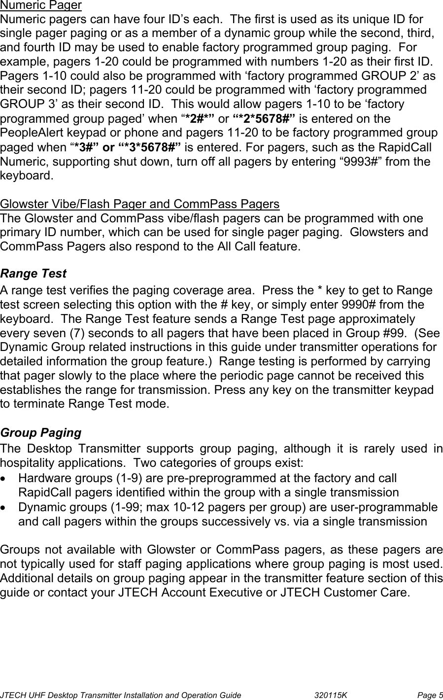
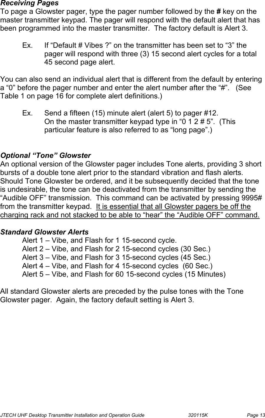
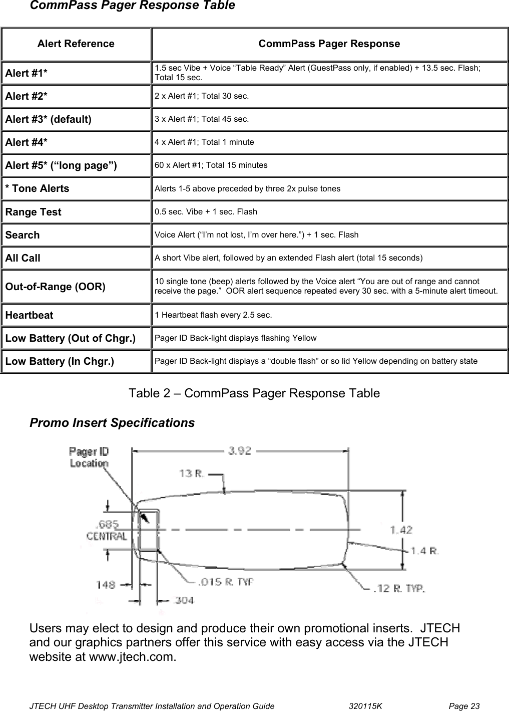
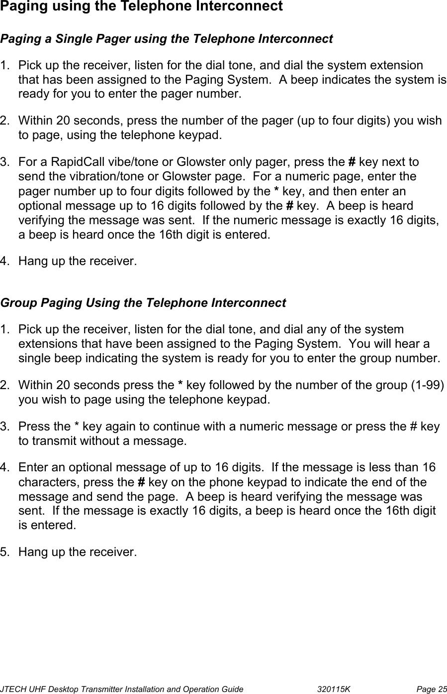
![JTECH UHF Desktop Transmitter Installation and Operation Guide 320115K Page 16 Glowster Response Table Alert Reference Transmitter Keypad Entry Pager Response Alert #1 0 PgrNumb # 1 1.5 sec Vibe + Voice Alert #1(if enabled) + 13.5 sec. Flash; Total 15 sec. Alert #2 0 PgrNumb # 2 2 x Alert #1; Total 30 sec. Alert #3 (default) PgrNumb # 3 x Alert #1; Total 45 sec. Alert #4 0 PgrNumb # 4 4 x Alert #1; Total 1 minute Alert #5 0 PgrNumb # 5 60 x Alert #1; Total 15 minutes Tone Alerts std. if tone is ordered Alerts 1-5 above preceded by 3 sets of 2 short pulse tone alerts Demo #1 0 PgrNumb # 6 1.5 sec. Vibe + 3.5 sec Flash; Total 5 sec. (No Voice Alert) Demo #2 0 PgrNumb # 7 5 beeps with 1 sec. Pauses (No Voice Alert) Range Test 9990 # 0.5 sec. Vibe + 0.1 sec. Beep Search 9999 # 1 Beep + Voice Alert #3 (if enabled) + 1 sec. Flash All Call 9998 # 2 x [ 0.4 sec. Vibe + 1 Short Beep ] Audible ON 9994 # None Audible OFF 9995 # None Out-of-Range ON 9996 # None Out-of-Range OFF 9997 # None Out-of-Range AlertN/A 1 Beep every 3 sec. + Voice Alert #2 (if enabled) every 30 sec. Heart Beat N/A 1 Heart Beat flash every 3 sec. Low Battery N/A 1 soft beep with a quick simultaneous heartbeat flash [ .025 sec. ] Pager OTA OFF (RapidCall Vibe/Tone) 9991 # 1 short tone alert following the over-the-air (OTA) transmission Pager OTA OFF (RapidCall Numeric) 9993 # 1 short tone alert following the over-the-air (OTA) transmission Table 1 – Desktop Transmitter Functions and Glowster Response Table](https://usermanual.wiki/JTECH-Communications/SERIES2600/User-Guide-444275-Page-22.png)