JTECH Communications SERVALERT200 Fixed Paging Base Station User Manual
JTECH Communications, Inc. Fixed Paging Base Station Users Manual
UserManual.wiki
>
JTECH Communications
>
SERVALERT200 User Manual
Users Manual
Navigation menu
Upload a User Manual
Namespaces
Wiki Guide
HTML
PDF
Info
Views
User Manual
Discussion / Help
Navigation


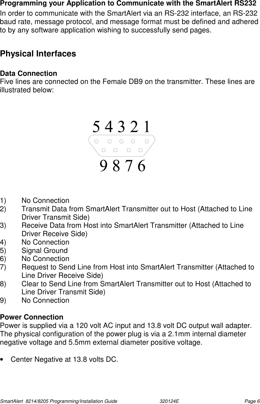

![SmartAlert 8214/8205 Programming/Installation Guide 320124E Page 16 • The telephone system then detects current flowing from its source of battery, through the SmartAlert transmitter with telephone's loop closure, and back to the telephone system. The current flow energizes relays in the telephone system, which connect bi-directional audio lines through Tip and Ring to the SmartAlert transmitter with telephone. • Once connected, the SmartAlert transmitter with telephone prompts the caller to enter a pager number. The caller must enter this number via a true DTMF tone type telephone. The DTMF tones must be at least 50 msec in duration with a 50 msec pause between digits. Numbers entered via Rotary dial, or Digital phone systems are not recognized by the SmartAlert transmitter with telephone. • Termination of the call can be accomplished in three different ways: 1) The calling party hangs up their telephone before the SmartAlert transmitter with telephone times out. This terminates the call at the telephone end, but not at the encoder’s end. The disconnect created by the caller hanging up its phone never makes it through the connection between the telephone system and the SmartAlert transmitter with telephone. To overcome this loss of a disconnect signal the encoder uses an ‘inactivity timer’ which will time out and terminate the call, in the encoder, after a loss of audio on Tip and Ring for approximately four seconds. 2) The SmartAlert transmitter with telephone times out before the calling part hangs up the telephone; this terminates the call at the encoders end. 3) The calling party enters the correct string of digits described in the section ‘Paging a Single Pager Using the Telephone Interconnect’. When the last (#) pound key is pressed the page is sent and the call is terminated. Appendix B - Detailed Technical Specifications SmartAlert Model 8214/8205Transmitter Item Specification Operating voltage 13.8 volts 1.7 amp external wall mount power supply Power Output 0.5 - 2 watts (Factory set; default is 2W) Modulation FSK 512 BPS Protocol POCSAG Antenna port 50 ohm BNC with Whip Antenna and rotating base Mounting Horizontal for Base Mounting/ Vertical for wall mount Data Format 7 digit extended [recommended] Operating frequency UHF synthesized 450 MHz-470 MHz Temperature Stability -30o C to +50 o C better than 5 ppm Size 13.3” L (338 mm) x 6.5" H (165 mm) x 2.37 "T (60 mm) Weight 4.3 lbs. (625 g)](https://usermanual.wiki/JTECH-Communications/SERVALERT200/User-Guide-670299-Page-22.png)