JULONG EDUCATIONAL TECHNOLOGY JL-V2 VOTE User Manual
JULONG EDUCATIONAL TECHNOLOGY CO., LTD. VOTE
Users Manual

User Manual
Attentions
General Note
z JL-V2 should be charged for about 2 hours before first-use. Please charge it when in low battery.
JL-V2 can keep normal operation continuously for about 7 hours, and with the stand-by time of about
150 hours (The charger indicator is red while charging and it turns green after full charged.).
z 8 Teacher’s JL-V2 or Student’s JL-V2 can be charged simultaneously by using 8-port charger.
z Power Supply: 3.6V, 3 Ni-MH batteries (AAA 1.5V batteries are also available).
General Note
z IPBOARD Vote Edition V2.0 is required to be installed before operation. Ensure that V4.0 driver is
well connected.
z The network ID of transceiver is supposed to be compatible with that said on the label stuck on the
back of JL-V2, or the driver may fail in connection.
z JL-V2 includes 7 models as follows: JL-V2 (08/16/24/32/64/128/256). The transceiver available for
JL-V2 (64) is different from that for JL-V2 (128) and JL-V2 (256), and they are not allowed to be used
interchangeably.
General Note
z JL-V2 defaults to auto-sleep mode. It will access to sleep mode and the backlight of LCD screen will
be off automatically without any operation in 9 minutes.
z Users can press Menu to wake up JL-V2. Besides, users can select whether access to sleep mode
manually in connectivity status with Menu.
Content
Attentions................................................................................................................................. 1
Content ..................................................................................................................................... 2
Ⅰ Brief Introduction............................................................................................................... 3
Ⅱ Unpacking JL-V2 Suite ...................................................................................................... 4
1 JL-V2...................................................................................................................................... 4
2 Standard Accessories ................................................................................................................ 5
Ⅲ Installation of IPBOARD Vote Edition V2.0...................................................................... 7
Ⅳ Run the Software.............................................................................................................. 14
1 Start IPBOARD Vote Edition Driver........................................................................................ 14
2 Start IPBOARD Vote Edition .................................................................................................. 14
3 Start voting system................................................................................................................. 14
Ⅴ Features of JL-V2 in-class Response System .............................................................. 16
1 Set Questions ...................................................................................................................... 16
2 Question Management ......................................................................................................... 17
3 Combined with JL-V2 response system to answer questions interactively ................................ 18
4 Statistics ............................................................................................................................. 19
Ⅵ Performance Specifications............................................................................................ 20
Ⅰ Brief Introduction
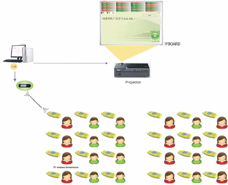
The in-class response system is very suitable for classroom training, creating a teaching
system integrated with in-class assessment, feedback and interaction. The response system
consists of IPBOARD Vote Edition V2.0 software, Teacher’s JL-V2 [JL-V2 (T)], Student’s JL-V2
[JL-V2 (S)] and transceiver [JL-V2 (I)]. With JL-V2, students can answer questions instantly and
teachers can gain instant feedback visually. It is designed for modern interactive teaching, aiming
at enabling teachers and students to be more engaged and interactive in class as well as enhancing
teaching methodology. The interactive effect is shown as Figure 1:
Figure 1
Ⅱ Unpacking JL-V2 Suite
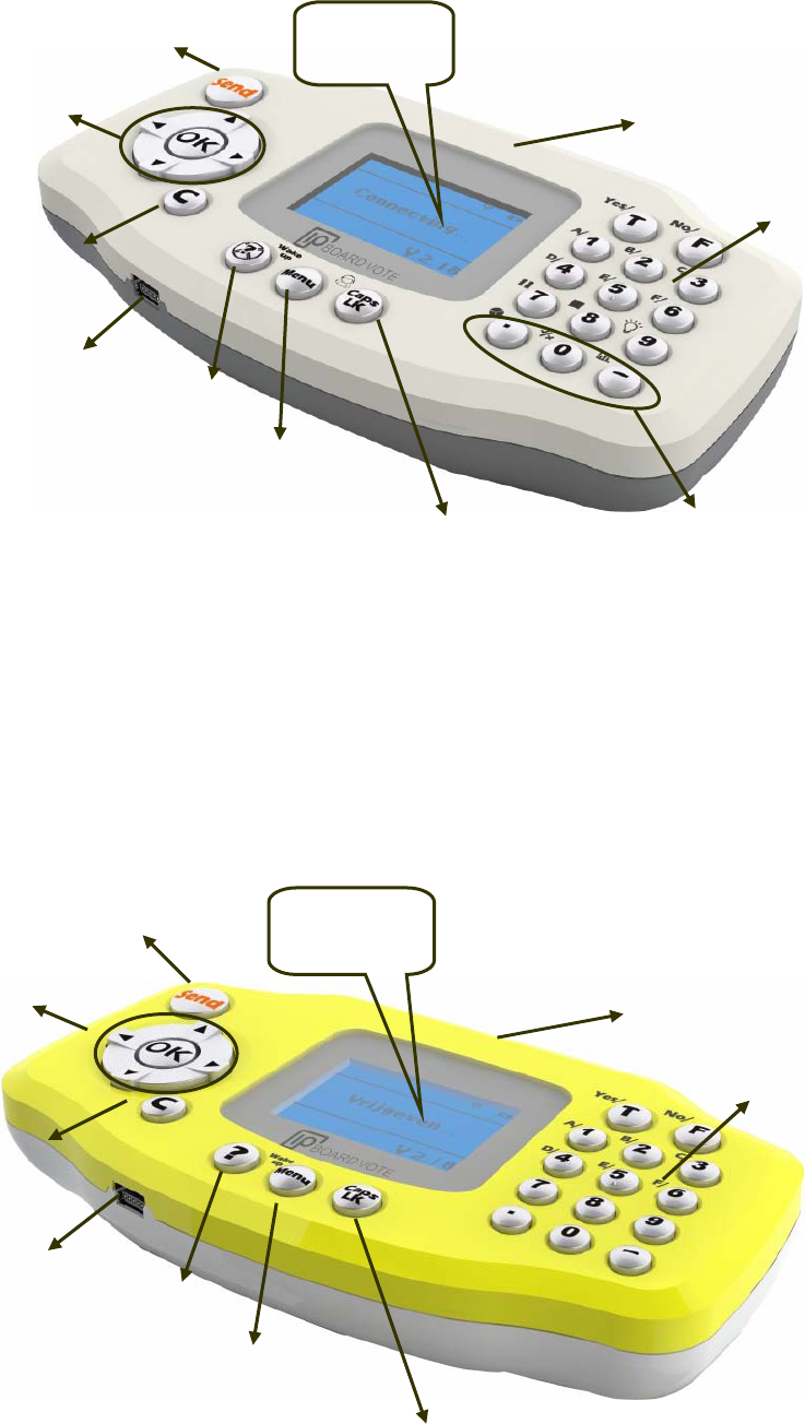
1 JL-V2
Statistic Report
Power Switch
Charge Interface
Ca
p
s Lock
Menu
Answer Ke
yp
ad
LCD Display
Submit
Button
Question Button
Clear Button
Confirm and
Next&Back
Buttons
Front of JL-V2 (T)
¾ Users can select whether access to sleep mode using the next/back keys on the Menu.
¾ Statistic Area is set on the JL-V2 (T), which enables teachers to check scores, true/false
report and right answers easily; and statistic reports are displayed in the form of bar chart.
Answer Keypad
Power Switch
LCD Display
Charge Interface
Submit Button
Caps Lock
Menu
Question Button
Clear Button
Confirm and
Next&Back
Buttons
Front of JL-V2 (S)
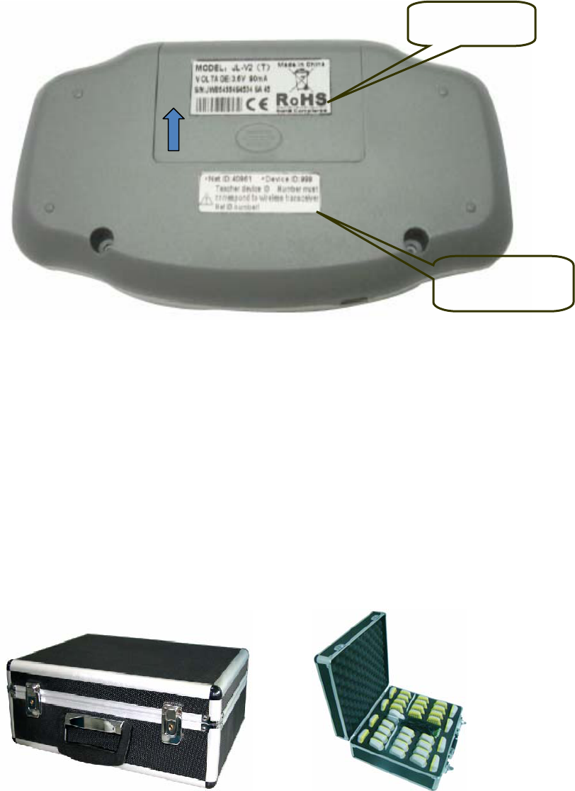
ROHS Identifier
NetID&DeviceID
Open Battery Cover
Back of JL-V2
¾ NetID, which is designed to build the network channel between transceiver and JL-V2, has
been set ex factory. To ensure successful connection, NetID is supposed to be compatible
with that said on the label stuck on the back of JL-V2.
¾ Device ID, which is used for identifying different terminals, is supposed to be
corresponding to student's number. The device ID of JL-V2 (T) is a fixed value of 999.
2 Standard Accessories
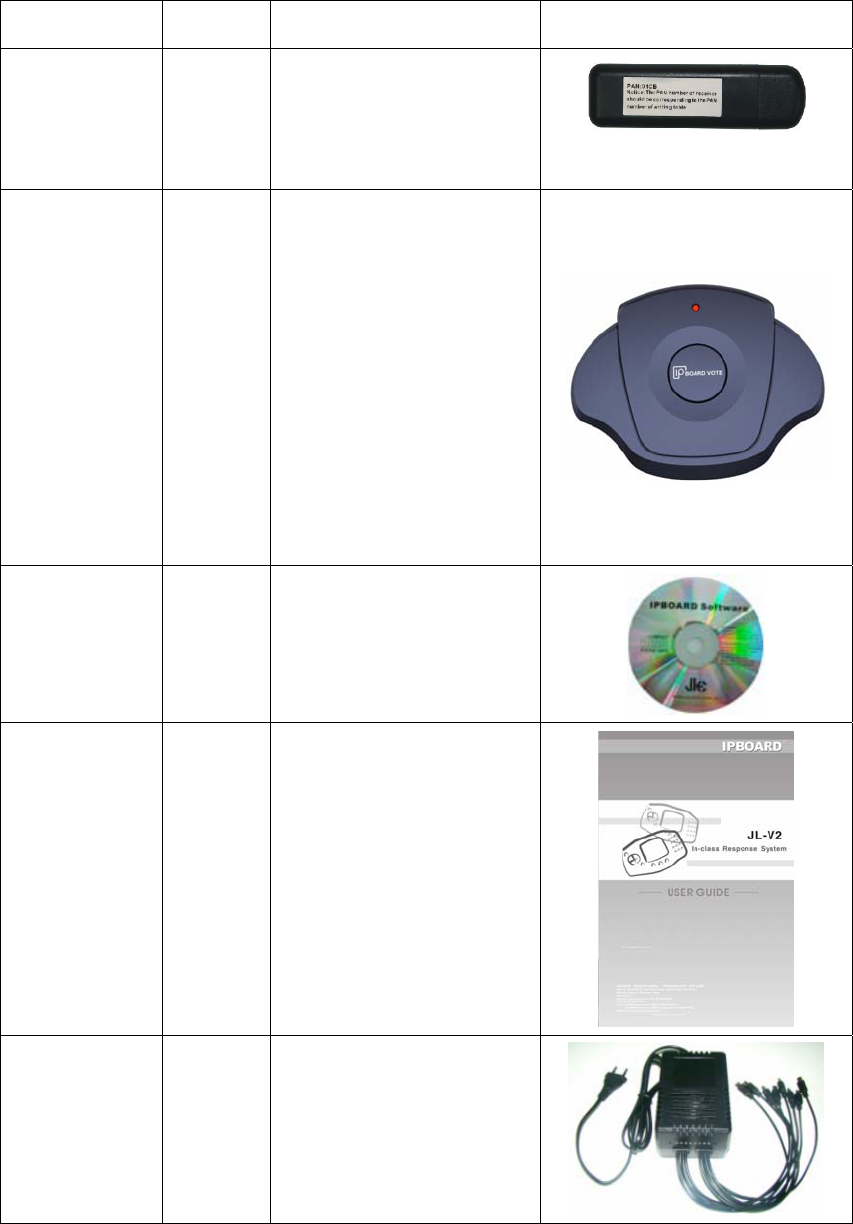
Standard Accessories include:
Description Quantity Function Figure
Transceiver
(1-to-64)
1 Ensure that the computer
connect with JL-V2
(8/16/24/32/64)
Transceiver
(1-to-128)/
Transceiver
(1-to-256)
1 Used together with JL-V2
(128), the appearance of
Student’s JL-V2 (128) is the
same with that of Student’s
JL-V2 (256). Transceiver
(1-to-128) and Transceiver
(1-to-256) are not allowed to
be used interchangeably.
IPBOARD Vote
Edition Disc
1 JL-V2 driver and
applications
JL-V2 User
Manual
1 Operation introduction
8-port Charger 1 Charge 8 JL-V2 (T) or
JL-V2 (S) simultaneously
Ⅲ Installation of IPBOARD Vote Edition V2.0
4.1 Insert IPBOARD Vote Edition disc
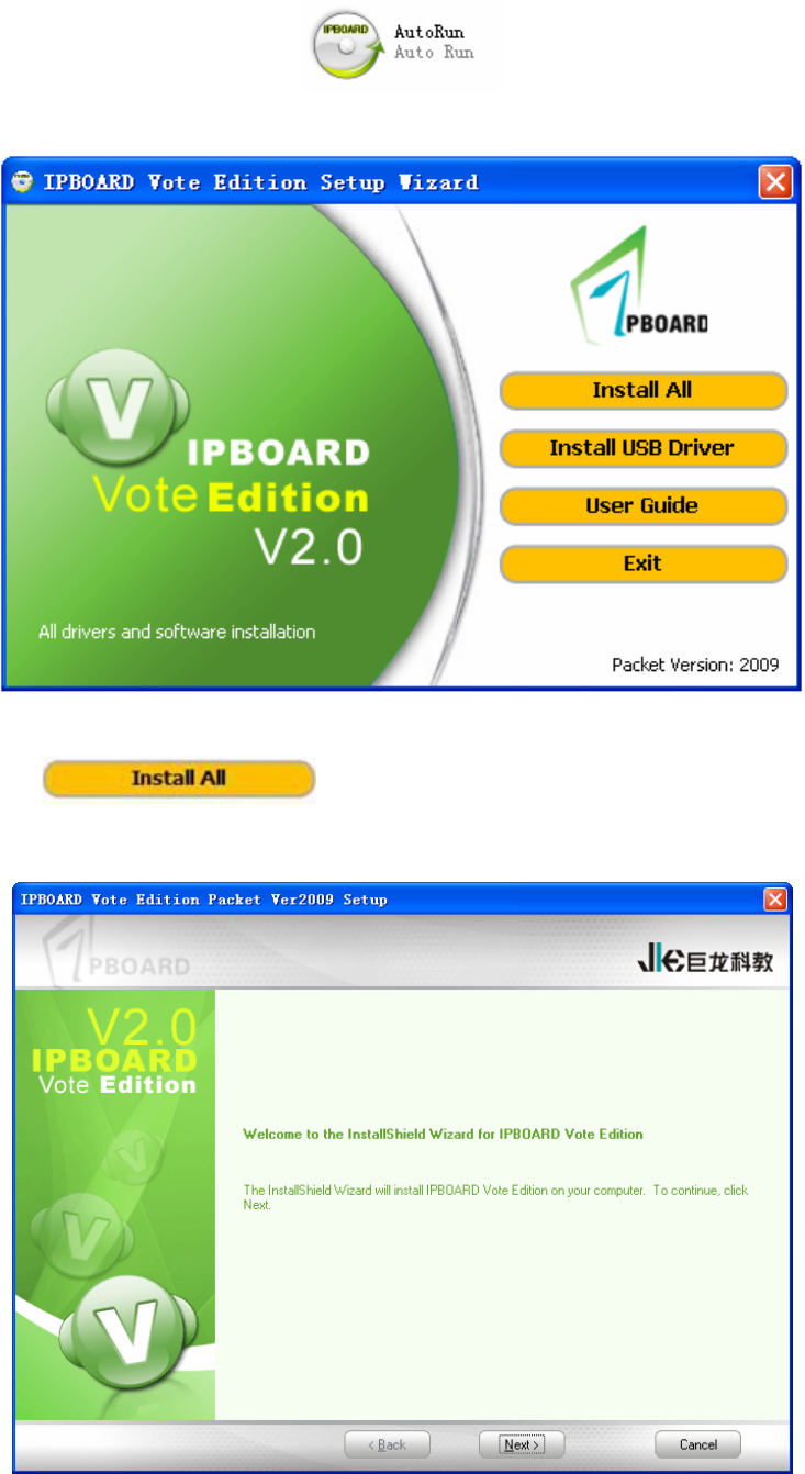
4.2 Click the program icon
4.3 Access to setup wizard window. As shown in Figure 2:
Figure 2
4.4 Click to install IPBOARD Vote Edition and driver.
4.5 Start the installation. As shown in Figure 3:
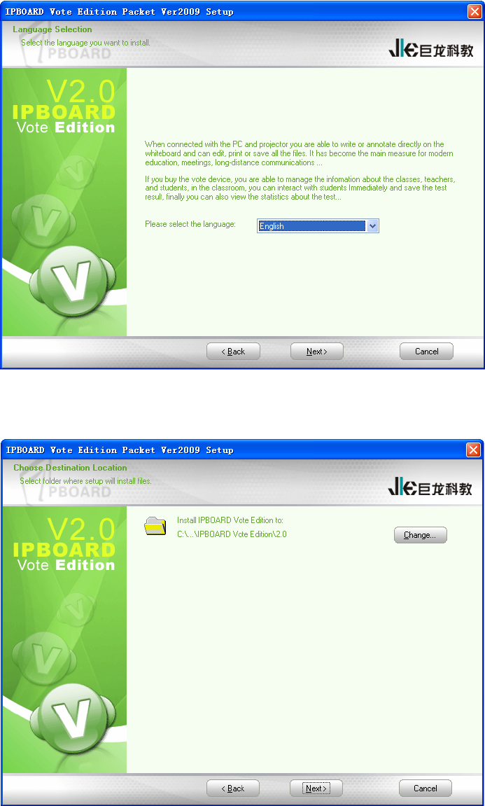
Figure 3
4.6 Select the language you want to install. As shown in Figure 4:
Figure 4
4.7 Choose destination location. As shown in Figure 5:
Figure 5
4.8 Select the database you want to install. As shown in Figure 6:
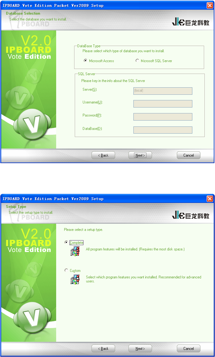
Figure 6
4.9 Select the setup type to install. As shown in Figure 7:
Figure 7
4.10 Complete installation. As shown in Figure 8:
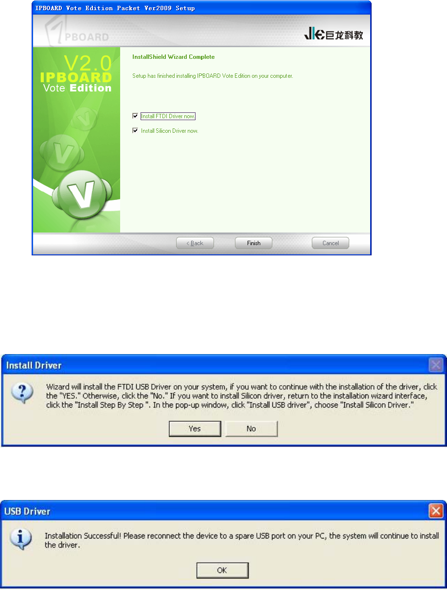
Figure 8
4.11 The USB driver installation prompt will be displayed after the software installation. FTDI
USB driver will be installed by default firstly; and then the Silicon driver for IPBOARD Tablet
(TB3124RDV) can be installed subsequently. As shown in Figure 9:
Figure 9
4.12 Complete the installation of FTDI driver. As shown in Figure 10:
Figure 10
4.13 The dialog of Silicon driver installation wizard will appear. As shown in Figure 11 and Figure
12:
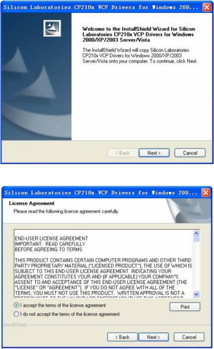
Figure 11
Figure 12
4.14 Choose destination location. As shown in Figure 13:
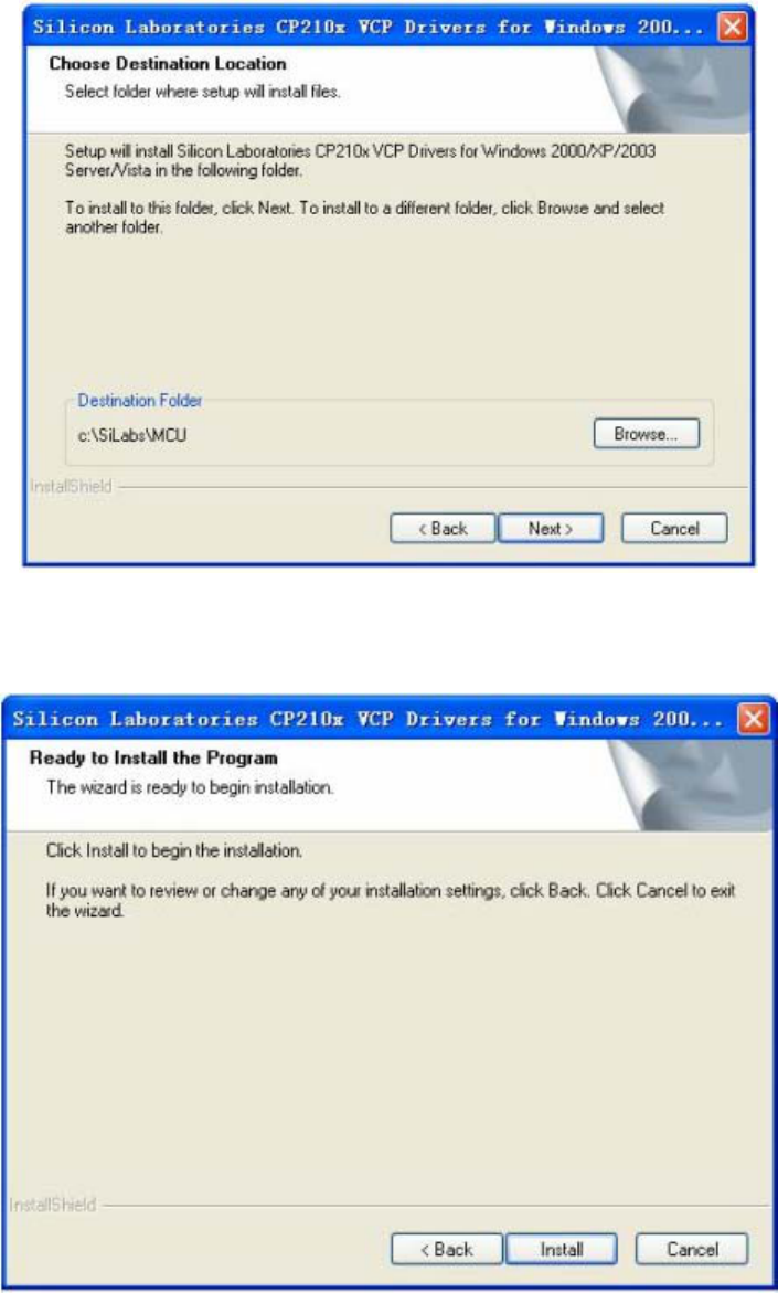
Figure 13
4.15 Start the installation. As shown in Figure 14:
Figure 14
4.16 Complete the installation of Silicon driver. As shown in Figure 15:
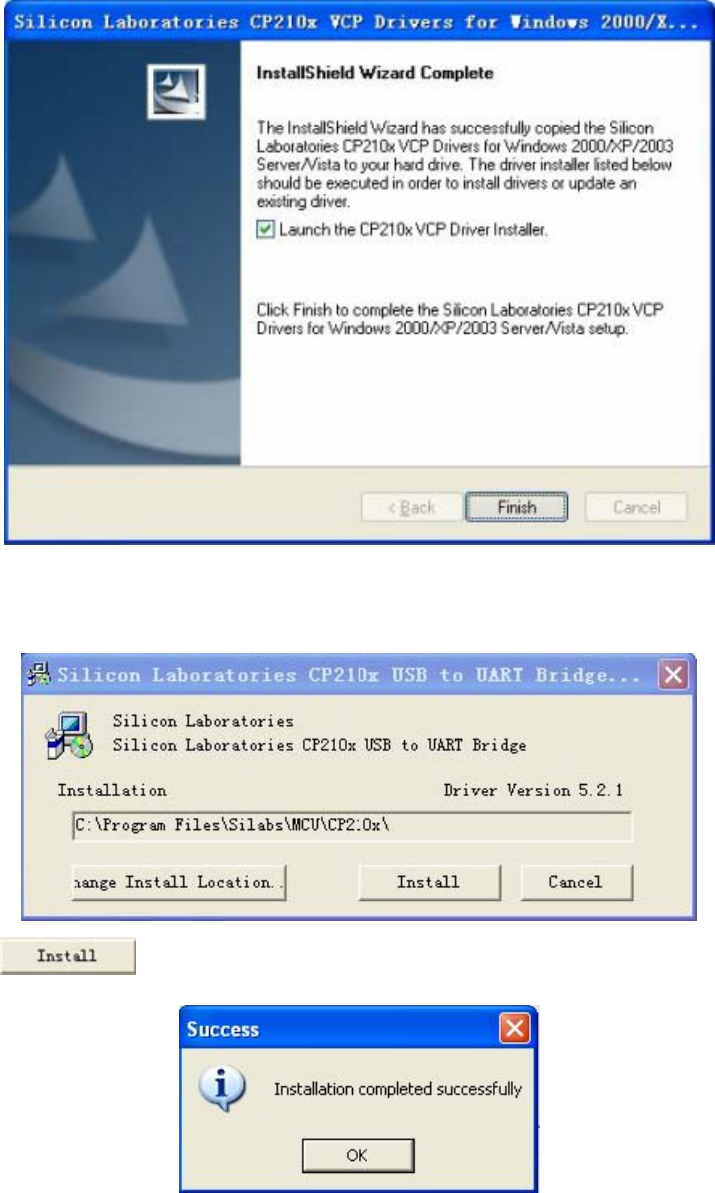
Figure 15
Click Finish, and the dialog as follows will pop up:
Click , and then plug-in transceiver to complete the installation.
Ⅳ Run the Software
1 Start IPBOARD Vote Edition Driver
Click 〝Start 〞 → 〝All programs 〞 →
→→ to run IPBOARD Vote
Edition driver. Then a tray icon will be displayed in status bar on lower-right corner of
the desktop.
If it shows 〝Communication with device failed〞, please make sure that the
transceiver is successfully connected, IPBOARD Vote Edition and USB
drivers have been correctly installed. And then click IPBOARD Driver on the
desktop.
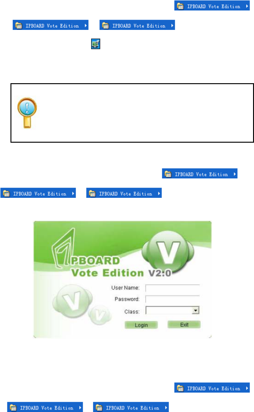
2 Start IPBOARD Vote Edition
1) Click 〝Start 〞 → 〝All programs 〞→ →
→, then a login window will pop up
as shown below:
2) Users can click Login to access IPBOARD Vote Edition directly.
3 Start voting system
1) Click 〝Start 〞 → 〝All programs 〞→
→ →, a dialog will appear as shown
below:
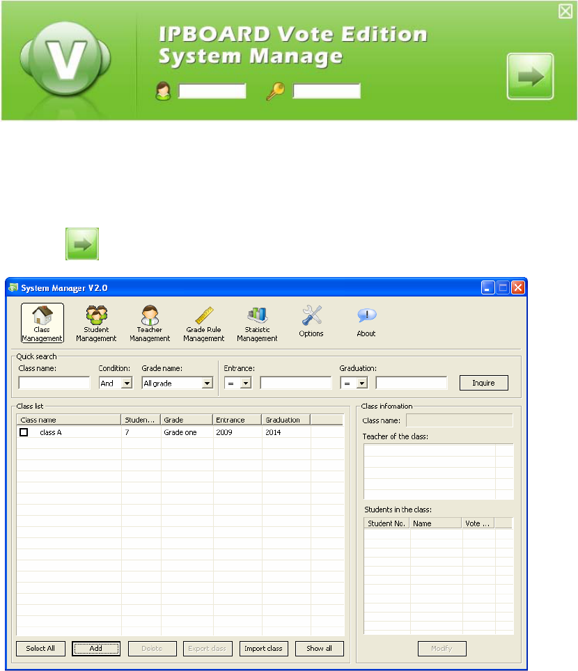
Figure 16
Key-in the administrator account to access voting system. The default administrator account is
Administrator and the password is julong.
2) Click to enter the system manage window as follows:
3)For adding, modifying or setting the information in Class Management, Student
Management, Teacher Management, Grade Management, Statistics Management and
System Management, please see the help text of IPBOARD Vote Edition for details.
Ⅴ Features of JL-V2 in-class Response System
Combining with IPBOARD Vote Edition V2.0, use JL-V2 to give and gain in-class feedback
instantly and create modern interactive classroom.
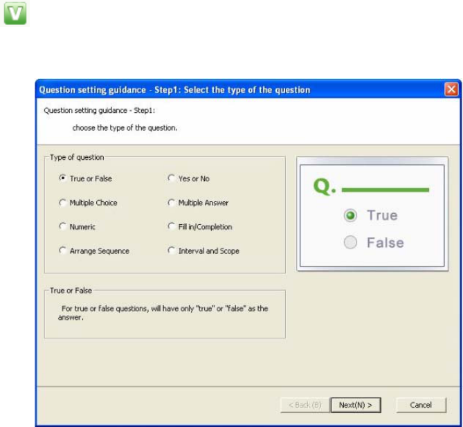
1 Set Questions
Click in the menu bar to vote. 8 different types of questions have been built in the
IPBOARD Vote Edition, as shown below:
¾ Two methods are available for setting questions --- Guide to Set Questions and Advanced
Question Setting. Use Guide to Set Questions to set questions as an example hereafter.
¾ Users can set the difficulty and mark of questions as well as test time.

2 Question Management
After setting question, the window as shown below will appear:
Fill in/Completion
¾ To enable easy management of test database for teachers, every set question can be added to
the test database. And then teachers can search, modify and reuse questions easily, which
provides an extremely convenient way for students to review lessons.
¾ To add questions to the test database, click Vote -> Add to Test Database -> Save Question,
and then name and save test question.
¾ Click Vote -> Question Management to classify, import, export, delete and name test
questions. See the help text of IPBOARD Vote Edition V2.0 for details.
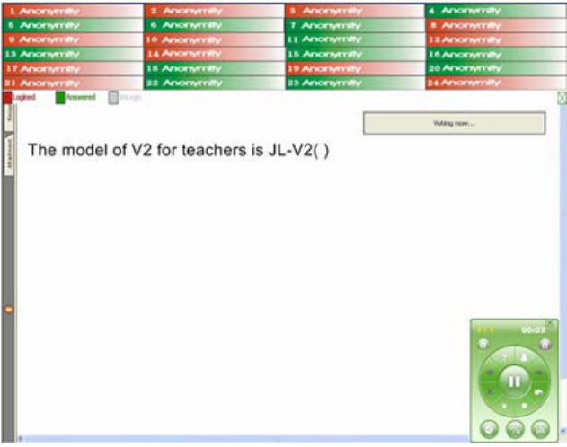
3 Combined with JL-V2 response system to answer questions interactively
3.1 Using JL-V2 (S) to answer questions
Students can key in answers using Answer Keypad on the JL-V2 (S), and then click OK or Send
to submit answers. To correct answers, key in and submit answers after clicking C button as
follows (e.g., using 1-to-24 JL-V2 in-class response system to conduct test):
3.2 Click Next button to skip to next question and Back button to previous question. In addition,
visual test results can be captured on JL-V2 (T) (displayed in the form of bar chart).
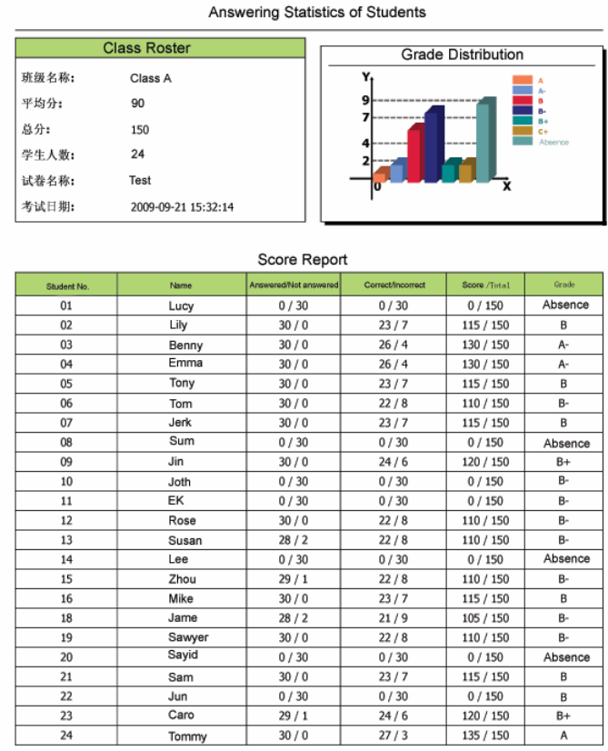
4 Statistics
Teachers can log on Vote Manage to view the detailed information of test results and scores, as
shown below:

Ⅵ Performance Specifications
Content Specification
Dimension 133mm X 75mm
Net Weight 230g (with battery)
Technical Specification
LCD Display 128 X 64 lattice (with backlight)
Transmission Frequency 2.4GHZ
Transmitting Power +2.5dBM
Quantity of Channels 16
Working Electricity Max.: <85 mA; Sleep mode: <65 mA; Stand-by mode: <4mA,
Working Voltage DC 3.6V
Power Less than 0.4W
Continuous operating hours More than 9 hours
Stand-by Time More than 240 hours
Power Supply 800mAH, 3 Ni-Mh batteries (AAA batteries are available)
Working Environment Temperature: -10℃~50℃
Relative Humidity: 30%~80% Non-condensing
Storage Environment Temperature: -25℃~70℃
Relative Humidity: 10%~90% Non-condensing
Transmission Technology Conforming to IEEE802.15.4 Standard
Transmitting Speed 57600bps
Charge Interface MINI USB
Quantity of keys 24
Data Transmission Range ≤20m (with obstacle), ≤120m (without obstacle)
Charger Charge 8 JL-V2 (T) or JL-V2 (S) simultaneously
Types of Questions 8 types available: True or False, Yes or No, Multiple Choice, Multiple
Answer, Numeric, Fill in/Completion, Arrange Sequence and Scope
Operation System Windows XP,Windows Vista,windows 7
This device complies with part 15 of the FCC rules. Operation is subject to the
following two conditions: (1) this device may not cause harmful interference,
and (2) this device must accept any interference received, including
interference that may cause undesired operation.
NOTE: The manufacturer is not responsible for any radio or TV interference
caused by unauthorized modifications to this equipment. Such modifications
could void the user’s authority to operate the equipment.
NOTE: This equipment has been tested and found to comply with the limits for
a Class B digital device, pursuant to part 15 of the FCC Rules. These limits
are designed to provide reasonable protection against harmful interference in
a residential installation. This equipment generates uses and can radiate
radio frequency energy and, if not installed and used in accordance with the
instructions, may cause harmful interference to radio communications.
However, there is no guarantee that interference will not occur in a particular
installation.
If this equipment does cause harmful interference to radio or television
reception, which can be determined by turning the equipment off and on, the
user is encouraged to try to correct the interference by one or more of the
following measures:
- Reorient or relocate the receiving antenna.
- Increase the separation between the equipment and receiver.
-Connect the equipment into an outlet on a circuit different from that to which
the receiver is connected.
-Consult the dealer or an experienced radio/TV technician for help.