JVC KENWOOD 417100 800 MHz Base Station/ Repeater User Manual
JVC KENWOOD Corporation 800 MHz Base Station/ Repeater Users Manual
Contents
- 1. Users Manual
- 2. Users Manual Safety Instructions
Users Manual

NXR-900
INSTRUCTION MANUAL
© B62-XXXX-00 (K)
09 08 07 06 05 04 03 02 01 00
MANUAL DE INSTRUCCTIONES
MODE D'EMPLOI
BASE-REPETIDOR DIGITAL 800MHz
800MHz DIGITAL BASE-REPEATER
BASE-RELAIS NUMÉRIQUE 800MHz
◆ Thisrepeaterisintendedforuseasaxedbasestationwith
the antenna located outdoors on the rooftop or on an antenna
tower.
◆ Thisrepeaterisdesignedfora13.8VDCpowersource!
Neverusea24VDCorhighersourcetopowertherepeater.
◆ UseonlythesuppliedDCcord.
◆ DonotremovetheferritecoreattachedtotheDCcord.Doing
somaycauseinterferencewithradiocommunications.
UNPACKING AND CHECKING EQUIPMENT
Note: Thefollowingunpackinginformationisforusebyyour
Kenwood dealer, an authorized Kenwood service center, or the
factory.
Carefullyunpacktherepeater.Werecommendthatyouidentify
theitemslistedinthefollowingtablebeforediscardingthe
packingmaterial.Ifanyitemsaremissingorhavebeendamaged
duringshipment,leaclaimwiththecarrierimmediately.
Item Part Number Quantity
Front glass B10-2781-XX 1
Dressedscrew N08-0563-XX 1
Bracket J29-0725-XX 2
Flatheadmachinescrew N32-4008-XX 4
Handleandscrewset K01-0421-XX 1
DC cord E30-3344-XX 1
Leadwirewithconnector(15pin) E37-1381-XX 1
Fuse(7.5A) F05-7521-XX 1
SYNCCable E30-7701-XX 1
Instruction Manual B62-1994-XX 1
INSTALLATION
To install the handles onto the front panel of the repeater, align
thehandleswiththeholesonthefrontpanel,thensecurethe
handlesusingthesuppliedscrews.
Please consult your dealer for installing the repeater and
antenna.
MICROPHONE
Connect an optional KMC-30, KMC-35, or KMC-9C Kenwood
microphone to the MICROPHONEjackonthefrontpanel.
OCXO UNIT (KXK-3):Option
The OCXO unit (KXK-3) is an Oven Controlled Crystal Oscillator
(OCXO)unit.
NOTICES TO THE USER
◆ Governmentlawprohibitstheoperationofunlicensedradio
transmitterswithintheterritoriesundergovernmentcontrol.
◆ Illegaloperationispunishablebyneand/orimprisonment.
◆ Referservicetoqualiedtechniciansonly.
FCC WARNING
Thisequipmentgeneratesorusesradiofrequencyenergy.Changes
ormodicationstothisequipmentmaycauseharmfulinterference
unlessthemodicationsareexpresslyapprovedintheinstruction
manual.Theusercouldlosetheauthoritytooperatethisequipmentif
anunauthorizedchangeormodicationismade.
INFORMATION TO THE DIGITAL DEVICE USER REQUIRED BY
THE FCC
Thisequipmenthasbeentestedandfoundtocomplywiththelimits
foraClassBdigitaldevice,pursuanttoPart15oftheFCCRules.
Theselimitsaredesignedtoprovidereasonableprotectionagainst
harmfulinterferenceinaresidentialinstallation.
This equipment generates, uses and can generate radio frequency
energyand,ifnotinstalledandusedinaccordancewiththe
instructions,maycauseharmfulinterferencetoradiocommunications.
However,thereisnoguaranteethattheinterferencewillnotoccur
inaparticularinstallation.Ifthisequipmentdoescauseharmful
interferencetoradioortelevisionreception,whichcanbedetermined
byturningtheequipmentoffandon,theuserisencouragedtotryto
correcttheinterferencebyoneormoreofthefollowingmeasures:
• Reorientorrelocatethereceivingantenna.
• Increasetheseparationbetweentheequipmentandreceiver.
• Connect the equipment to an outlet on a circuit different from that to
whichthereceiverisconnected.
• Consultthedealerfortechnicalassistance.
THANK YOU!
WearegratefulyoupurchasedthisKenwoodrepeater.We
believethiseasy-to-programrepeaterwillbehighlyeffectivein
yourcommunicationssystem,andwillkeeppersonneloperating
atpeakefciency.
Kenwood incorporates the latest in advanced technology into
allofourproducts.Asaresult,wefeelstronglythatyouwillbe
pleasedwiththequalityandfeaturesofthisproduct.
PRECAUTIONS
• Donotexposetheunittorainormoisture;topreventreor
electricshock.
• Donotopentheunitunderanycircumstances;toavoidrisk
ofelectricshock.
• Donotexposetheunittolongperiodsofdirectsunlight,nor
placeitclosetoheatingappliances.
• Donotplacetheunitinexcessivelydustyand/orhumid
areas,noronunstablesurfaces.
• Ifyoudetectanabnormalodororsmokecomingfromthe
unit,disconnectthepowerfromtheunitimmediately.Contact
your Kenwood servicecenterordealer.
NXR-900 INSTRUCTION MANUAL
800MHz DIGITAL BASE-REPEATER
The AMBE+2TMvoicecodingTechnologyembodiedinthisproduct
isprotectedbyintellectualpropertyrightsincludingpatentrights,
copyrightsandtradesecretsofDigitalVoiceSystems,Inc.Thisvoice
codingTechnologyislicensedsolelyforusewithinthisCommunications
Equipment.TheuserofthisTechnologyisexplicitlyprohibitedfrom
attemptingtoextract,remove,decompile,reverseengineer,or
disassembletheObjectCode,orinanyotherwayconverttheObject
Codeintoahuman-readableform.U.S.PatentNos.#5,870,405,
#5,826,222,#5,754,974,#5,701,390,#5,715,365,#5,649,050,
#5,630,011,#5,581,656,#5,517,511,#5,491,772,#5,247,579,
#5,226,084and#5,195,166.
REPEATER OPERATION
Note: Pleaseconsultyourdealerforprogrammingtherepeater.Due
tothefrequencystabilityonthe6.25kHzbandwidthchannel,when
operatingtherepeaterusinganoptionalOCXOunit,allowtheunitto
warmupfor24hoursafterturningthepoweron.
Afterturningonthepower,waitforapproximately10secondsfor
theVCXOor5minutesfortheOCXO(whenmounting)towarmup.
Duringthistime,theCH/STATUSDisplaywillblink.Thekeyswill
functionwhentheyarepressed.
Whenpowerisappliedtotheunit,thePOWER indicator lights
green.TurntheVOLUMEcontrolclockwiseuntilaclicksounds,
tounmutetheaudio.Rotatetoadjusttheaudio.Turnthe
VOLUMEcontrolcounterclockwisefullytomutetheaudio.
The BUSYindicatorlightsgreenwhilereceivingasignalandthe
TXindicatorlightsredwhiletransmitting.
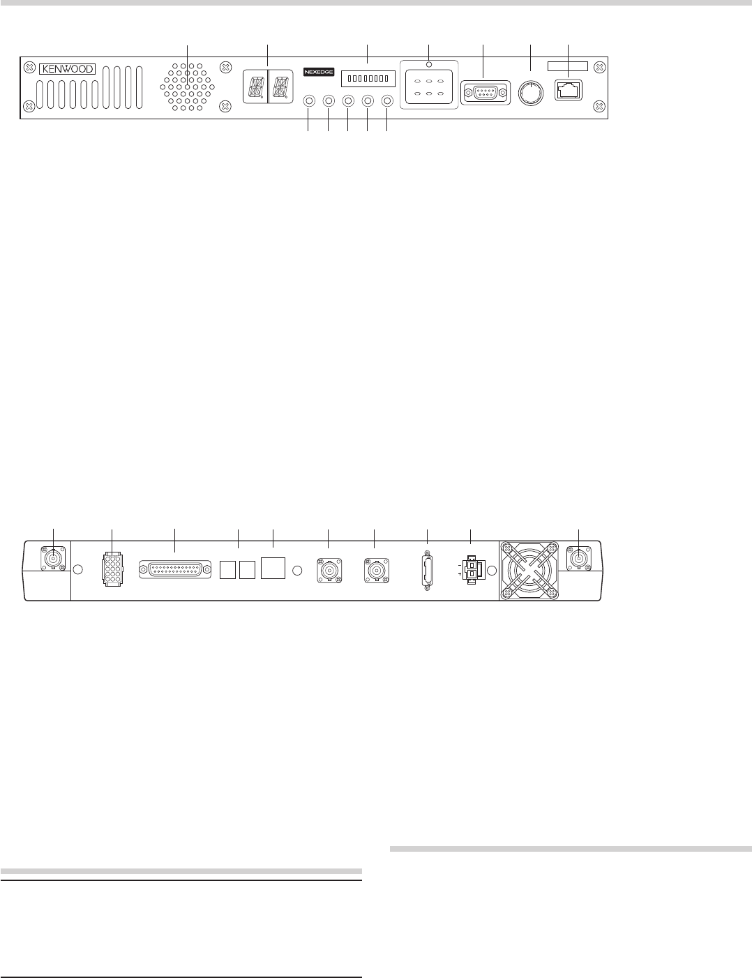
■ Rear Panel
q RX IN jack
ConnectanRXantennaoraduplexertothisBNC
receptacle.
w TEST/SPKR jack
Testinput/outputjack.Connectanexternalspeakerto
thisjack.
e CONTROL I/O jack
Connect a repeater controller or a remote panel to this
DB-25interface.
r SYNC 1 / 2 jack
Connect to another repeater to use synchronous frame
signalingfordigitaltrunking.
t LAN jack
ConnecttoEthernet.
CONTROLS AND FUNCTIONS
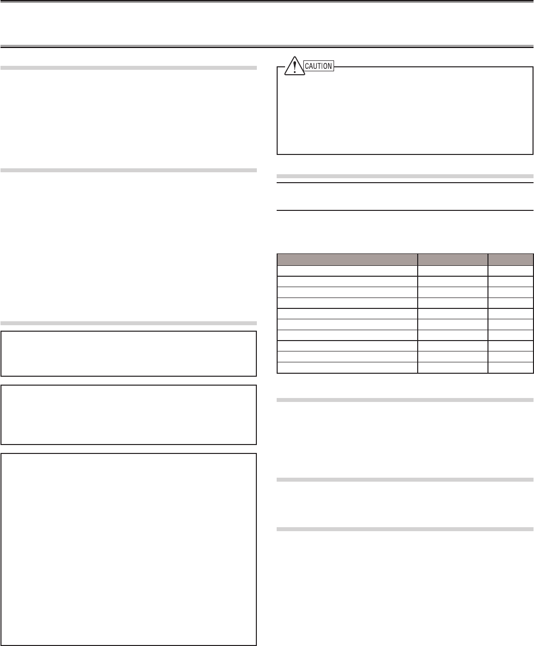
■ Front Panel qw r t y u
io
e
qwr t y u
e
MICROPHONE
VOLUME
COM OFF/
POWERCTRL OCXO BUSY TX
1 2
MON
TAKE
OVER
RPT
DISABLE
A B C
3 4 5 6 7 8
STATUS
TEST/SPKR
RX TX
CONTROL I/O SYNC
1 2 LAN REF OUT REF IN
FUSE
75
DC 13.8V
y REF OUT jack
Connecttoanotherrepeaterwithinthesitetosupplya
referencesignal.
u REF IN jack
Connectfromanotherrepeaterwithinthesitetoreceivea
referencesignal.
i FUSE
Insert7.5Abladefuseintothisfuseholder.
o DC 13.8V jack
Connecta13.8VDCpowersupplytothisjack.
⑩ TX OUT jack
ConnectaTXantennaoraduplexertothisBNCreceptacle.
io⑩
TRANSCEIVER OPERATION
■ Receive
Adjustthevolumetoyourdesiredlevel.Youmayneedto
readjustthevolumeifyouarehavinginterferencewhilereceiving
amessagefromyourdispatcheroranothermemberinyoureet.
The BUSYindicatorlightsgreenwhileasignalisbeingreceived.
■ Transmit
1 Listentothechannelbeforetransmitting,tomakesureit
isnotbeingused.
2 Press the microphone PTTswitch,thenspeakinyour
normalspeakingvoice.
The TXindicatorlightsredwhiletransmitting.
3 Whenyounishspeaking,releasethePTTswitch.
!0
!1
!2
q Speaker
w CH/STATUS Display
Two17-segmentdigitsdisplaythechannelnumber,name,
orstatus.
e STATUS indicator
Indicatesthestatusoftherepeater.(NXDNmode)
r Programmable Function keys
Pressthesekeystoactivatetheirprogrammable
functions.
t COM jack
Connect to the PC using a RS-232C standard DB9
(Female)crosscable.
y VOLUME control
Turnclockwiseuntilaclicksounds,tounmutetheaudio.
Rotatetoadjusttheaudio.Turncounterclockwisefullyto
mutetheaudio.
u MICROPHONE jack
Connectamicrophonetothis8-pinmodularjack.
i POWER indicator
LightsgreenwhenpowerissuppliedtotheDC 13.8V
jack.Blinksredwhenanabnormalvoltageispresent.
Whileblinking,therepeatercannotbeused.
o TX indicator
Lightsredwhiletransmitting.
!0 BUSY indicator
Lightsgreenwhileasignalisbeingreceived.
!1 OCXO indicator
TheOCXOindicatorshowsthestateofthereference
10MHzoscillator:
LightsGreenwhenusingareferencesignalfroman
optionalOCXOunit(KXK-3).
LightsOrangewhenusingareferencesignalfromanother
repeater.
Lightsredwhennoreferencesignalisavailableorwhen
anerroroccurs.
Doesnotlightwhenthereferencesignalisaninternal
VCXOsignal.
!2 CTRL indicator
TheCTRLindicatorshowsthecontrolchannelstatus
whileusingDigitaltrunking:
LightsGreenwhentherepeaterisusedascontrolchannel.
BlinksGreenwhenusinganon-dedicatedcontrolchannel.


TERMINAL
MIC(Modular Jack)
Pin Numbe
r
Pin Name Description Specification I/O notes
1NC
2 SB Power Output 13.8V
3 GND GND GND
4 PTT PTT Signal Input Impeadance 100kΩI
5 MICG MIC GND MIC GND
6 MIC MIC Input 600ΩI
7 HOOK Hook Detection Input Impeadance 100kΩI
8NC
COM (D-SUB 9Pin) CONNECTOR
Pin Numbe
r
Pin Name Description Specification I/O notes
1 CD Carrier Detect Conform to RS-232C standard I
2 RD Receive Data Conform to RS-232C standard I
3 SD Send Data Conform to RS-232C standard O
4 DTR Data Terminal Ready Conform to RS-232C standard O
5 SG GND GND
6 DSR Data Set Ready Conform to RS-232C standard I
7 RTS Request to Send Conform to RS-232C standard O
8 CTS Clear to Send Conform to RS-232C standard I
9 CI Ringer DET Conform to RS-232C standard I
TEST/SPEAKER CONNECTOR
Pin Numbe
r
Pin Name Description Specification I/O notes
1 SB Power Output 13.8V
2 SB Power Output 13.8V
3NC
4 GND GND GND
5 GND GND GND
6 SPG Speaker GND Speaker GND
7 RD RX Audio Output Load impedance 4.7kΩO not De-emphasis
8 RSSI RSSI Signal Output Output Level 0 to 5V O
9 SPI Internal Speaker Input Short with "SPO" I
10 AO1 Open Collector Terminal
A
llowable current value MAX 200m
A
O
11 AO2 Open Collector Terminal
A
llowable current value MAX 200m
A
O
12 SPO External Speaker Output Output Level 3W (5% Distortion) O
13 AO3 Open Collector Terminal
A
llowable current value MAX 200m
A
O
14
A
O4 O
p
en Collector Terminal
A
llowable current value MAX 200m
A
O
15
A
O5 Open Collector Terminal
A
llowable current value MAX 200m
A
O

Control I/O (D-SUB 25Pin) CONNECTOR
Pin Numbe
r
Pin Name Description Specification I/O notes
1NC
2NC
3NC
4 AI1 ro
g
rammable Function In
p
ut Input Impeadance 47kΩI
5
A
I2 ro
g
rammable Function In
p
ut Input Impeadance 47kΩI
6
A
I3 ro
g
rammable Function In
p
ut Input Impeadance 47kΩI
7 DG Digital GND
8 TD TX Audio Input Input Impeadance 600ΩI not Pre-emphasis
9 TA TX Audio Input Input Impeadance 600ΩI Pre-emphasis
10 RD RX Audio Output Load impedance 4.7kΩO not De-emphasis
11 RA RX Audio Output Load impedance 4.7kΩO De-emphasis
12 RXG RX Signal GND
13 SPM Speaker Mute Input Impeadance 47kΩI
14 BER CLK For Bit Error Rate Clock CMOS O
15 EMON External Monitor Switch Input Impeadance 47kΩI
16 EPTT External PTT Switch Input Impeadance 47kΩI
17 SC Squelch Control Output Level 0 or 3.3V O
18 BER DAT For Bit Error Rate Data CMOS O
19 TXG TX Signal GND
20 IO1
P
ro
g
rammable Function I/O 1 Input Impeadance 47kΩI/O Output Level 0 to 5V
21 IO2
P
ro
g
rammable Function I/O
2
Input Impeadance 47kΩI/O Output Level 0 to 5V
22 IO3
P
ro
g
rammable Function I/O
3
Input Impeadance 47kΩI/O Output Level 0 to 5V
23 IO4
P
ro
g
rammable Function I/O
4
Input Impeadance 47kΩI/O Output Level 0 to 5V
24 IO5
P
ro
g
rammable Function I/O
5
Input Impeadance 47kΩI/O Output Level 0 to 5V
25 IO6
P
ro
g
rammable Function I/O
6
Input Impeadance 47kΩI/O Output Level 0 to 5V
LAN(Modular Jack)
Pin Numbe
r
Pin Name Description Specification I/O notes
1 TD+ TX Signal+ Conform to IEEE802.3 standard O 100Mbps
2 TD- TX Signal- Conform to IEEE802.3 standard O 100Mbps
3 RD+ RX Signal+ Use Designated Transformer I 100Mbps
4NC
5NC
6 RD- RX Signal- Use Designated Transformer I 100Mbps
7NC
8NC

SYNC1, 2 Connector (There are two connectors)
Pin Numbe
r
Pin Name Description Specification I/O notes
1 FRMA RS-458 Diffrential Signal A Conform to RS485 I/O
2NC
3NC
4 FRMB RS-458 Diffrential Signal B Conform to RS485 I/O
RX ANT Impeadance 50Ω
TX ANT Impeadance 50Ω
REF IN External Reference Signal Input(10MHz). Impedance : more than 1kohm
REF OUT Reference Signal Distribution(10MHz). Load impedance more than 20ohm.

MANDATORY SAFETY INSTRUCTIONS TO INSTALLERS AND USERS
• Use only manufacturer or dealer supplied antenna.
• Antenna Minimum Safe Distance: 30 cm (1 foot).
• Antenna Gain: 0 dBd referenced to a dipole.
The Federal Communications Commission has adopted a safety standard for human
exposure to RF (Radio Frequency) energy which is below the OSHA (Occupational Safety
and Health Act) limits.
• Antenna Mounting: The antenna supplied by the manufacturer or radio dealer must not be
mounted at a location such that during radio transmission, any person or persons can
come closer than the above indicated minimum safe distance to the antenna, i.e. 30 cm
(1 foot).
• To comply with current FCC RF Exposure limits, the antenna must be installed at or
exceeding the minimum safe distance shown above, and in accordance with the
requirements of the antenna manufacturer or supplier.
• Vehicle installation: The antenna can be mounted at the center of a vehicle metal roof or
trunk lid, if the minimum safe distance is observed.
• Base Station Installation: The antenna should be fixed-mounted on an outdoor permanent
structure. RF Exposure compliance must be addressed at the time of installation.
Antenna substitution: Do not substitute any antenna for the one supplied or recommended
by the manufacturer or radio dealer.
You may be exposing person or persons to excess radio frequency radiation. You may
contact your radio dealer or the manufacturer for further instructions.
Maintain a separation distance from the antenna to person(s) of at least
30 cm (1 foot).
You, as the qualified end-user of this radio device must control the exposure conditions of
bystanders to ensure the minimum separation distance (above) is maintained between the
antenna and nearby persons for satisfying RF Exposure compliance. The operation of this
transmitter must satisfy the requirements of Occupational/Controlled Exposure
Environment, for work-related use, transmit only when person(s) are at least the minimum
distance from the properly installed, externally mounted antenna. Transmit only when
people outside the vehicle are at least the recommended minimum lateral distance away
from the antenna/vehicle