JVC KW NSX1EU NSX1[EU] User Manual LVT2359 003A
KW-NSX1EU KW-NSX1EU INSTALLATION MANUAL (Europe) LVT2359-003A
User Manual: JVC KW-NSX1EU KW-NSX1EU Английский, Русский, Испанский, ИНСТРУКЦИЯ ПО УСТАНОВКЕ
Open the PDF directly: View PDF ![]() .
.
Page Count: 6

1
KW-NSX1
Installation/Connection Manual
Manual de instalación/conexión
Руководство по установке/подключению
Parts list for installation and connection
If any item is missing, consult your JVC IN-CAR
ENTERTAINMENT dealer immediately.
ENGLISH
This unit is designed to operate on 12 V DC, NEGATIVE ground
electrical systems. If your vehicle does not have this system, a
voltage inverter is required, which can be purchased at JVC IN-CAR
ENTERTAINMENT dealers.
WARNINGS
• DO NOT install any unit or wire any cable in a location where;
– it may obstruct the steering wheel and gearshift lever operations,
as this may result in a traffic accident.
– it may obstruct the operation of safety devices such as air bags, as
this may result in a fatal accident.
– it may obstruct visibility.
• DO NOT operate any unit while manipulating the steering wheel, as
this may result in a traffic accident.
• The driver must not watch the monitor while driving. It may lead to
carelessness and cause an accident.
• If you need to operate the unit while driving, be sure to look around
carefully or you may be involved in a traffic accident.
• If the parking brake is not engaged, “Parking Brake” appears on the
monitor, and no playback picture will be shown.
– This warning appears only when the parking brake lead is
connected to the parking brake system built in the car.
To prevent short circuits, we recommend that you disconnect the
battery’s negative terminal and make all electrical connections before
installing the unit.
• Be sure to ground this unit to the car’s chassis again after
installation.
• Be sure any cable is not caught on the car’s chassis or under seats.
Notes on electrical connections:
• Replace the fuse with one of the specified rating. If the fuse blows
frequently, consult your JVC IN-CAR ENTERTAINMENT dealer.
• It is recommended to connect speakers with maximum power
of more than 50 W (both at the rear and at the front, with an
impedance of 4 to 8 Ω).
• To prevent short circuits, cover the terminals of the UNUSED leads
with insulating tape.
• The heat sink becomes very hot after use. Be careful not to touch it
when removing this unit.
• At the time of installation, be sure to fix all wires (wires both from
this unit and from the car itself) in a way that no wires can come
into contact with heat sinks on the rear and side of the unit.
Heat sink
Sumidero térmico
Радиатор
LVT2359-003A
[EU]
0412EHHMDWJEIN
EN, SP, RU
© 2012 JVC KENWOOD Corporation
Round head screws (M5 × 8 mm)
Tornillos de cabeza esférica (M5 × 8 mm)
Болты с круглой головкой (M5 x 8 мм)
Flat head screws (M5 × 8 mm)
Tornillos de cabeza plana (M5 × 8 mm)
Болты с плоской головкой (M5 x 8 мм)
При отсутствии какого-либо элемента немедленно свяжитесь с
дилером автомобильного специалиста JVC.
РУССКИЙ
Это устройство разработано для эксплуатации на 12
. Если Ваш
автомобиль не имеет этой системы, требуется инвертор
напряжения, который может быть приобретен у дилера
автомобилнего специалиста JVC.
ПРЕДУПРЕЖДЕНИЯ
• НЕ устанавливайте устройства и не прокладывайте провода в
местах, где:
– возникает препятствие для функционирования руля
и рычага переключения скоростей, так как это может
привести к аварии;
– возникает препятствие срабатыванию устройств
безопасности, например, пневмоподушки, что может
привести к несчастному случаю со смертельным исходом;
– может ухудшиться обзор.
• НЕ используйте устройство, когда управляете рулем; это
может привести к аварии.
• Водителю не следует смотреть на монитор во время
вождения. Это может быть опасно и может стать причиной
аварии.
• Если данное устройство используется во время поездки
на автомобиле, следует, не отвлекаясь, следить за
дорогой, иначе может произойти дорожно-транспортное
происшествие.
• Если стояночный тормоз не включен, на мониторе появляется
сообщение “Parking Brake (Ручной Тормоз)” и изображение
воспроизведения отображаться не будет.
– Это предупреждение появляется только в том случае, если
провод стояночного тормоза подключен к стояночной
тормозной системе автомобиля.
Для предотвращения коротких замыканий мы рекомендуем
Вам отсоединить отрицательный разъем аккумулятора и
осуществить все подключения перед установкой устройства.
•
.
• Убедитесь в том, что никакой из кабелей не зацепился за
шасси автомобиля или не зажат под сиденьями.
:
• Заменяйте предохранитель другим предохранителем
указанного класса. Если предохранитель сгорает слишком
часто, обратитесь к дилеру автомобилнего специалиста JVC.
• Рекомендуется подключать динамики с максимальной
мощностью более 50 Вт (к задней и передней панели
устройства, с полным сопротивлением от 4 8 ).
• Для предотвращения ороткого замыкания заклейте
НЕИСПОЛЬЗУЕМЫЕ концы изолирующей лентой.
• Радиатор во время использования сильно нагревается.
Старайтесь его не трогать во время удаления устройства.
• При установке обязательно закрепляйте все провода
(провода как от данного устройства, так и от самого
автомобиля) таким образом, чтобы провода не могли войти в
контакт с теплоотводными деталями в задней и боковой части
устройства.
ESPAÑOL
Esta unidad está diseñada para funcionar con 12 V de CC, con
sistemas eléctricos de masa NEGATIVA. Si su vehículo no posee
este sistema, será necesario un inversor de tensión, que puede ser
adquirido en los concesionarios de JVC de equipos de audio para
automóviles.
ADVERTENCIAS
• NO instale ningún receptor o tienda ningún cable en una ubicación
donde;
– donde pueda obstruir la maniobra del volante de dirección y del
cambio de engranajes, con el consiguiente riesgo de accidentes de
tráfico.
– donde pueda obstruir el funcionamiento de dispositivos de
seguridad tales como bolsas de aire, pues podría resultar en un
accidente fatal.
– donde pueda obstruir la visibilidad.
• NO OPERE la unidad mientras está maniobrando el volante de
dirección, pues podría producirse un accidente de tráfico.
• El conductor no debe mirar el monitor mientras conduce. Podría
producirse un descuido, y causar un accidente.
• Si necesita operar la unidad mientras conduce, asegúrese de mirar
atentamente a su alrededor pues de lo contrario, se podría producir
un accidente de tráfico.
• Si el freno de mano no está en uso, aparecerá “Parking Brake (Freno
de Mano)” en la pantalla y no se mostrará ninguna secuencia de
imagen.
– Esta advertencia aparece únicamente cuando el cable del freno de
estacionamiento se encuentra conectado al sistema del freno de
estacionamiento incorporado al automóvil.
Para evitar cortocircuitos, recomendamos que desconecte el terminal
negativo de la batería y que efectúe todas las conexiones eléctricas antes
de instalar la unidad.
• Asegúrese de volver a conectar a masa esta unidad al chasis
del automóvil después de la instalación.
• Asegúrese de que ningún cable quede atrapado en el chasis del
automóvil o debajo de los asientos.
Notas sobre las conexiones eléctricas:
• Reemplace el fusible por uno con la corriente especificada. Si el fusible
se quemase frecuentemente consulte con su concesionario de JVC de
equipos de audio para automóviles.
• Se recomienda conectar los altavoces con una potencia máxima de
más de 50 W (tanto atrás como adelante, con una impedancia de
4 a 8 Ω).
• Para evitar cortocircuitos, cubra los cables NO UTILIZADOS con
cinta aislante.
• El sumidero térmico estará muy caliente después del uso. Asegúrese
de no tocarlo al desmontar esta unidad.
• Al realizar la instalación, asegúrese de fijar todos los cables (tanto los
que proceden de esta unidad como los del vehículo en sí) de manera
tal que ninguno quede en contacto con los disipadores térmicos de las
partes traseras y laterales de la unidad.
Main unit/Sleeve/Trim plate
Unidad principal/Cubierta/Placa de guarnición
Главное устройство/Муфта/Декоративную панель
Lista de piezas para instalación y conexión
Si hay algún elemento faltante, consulte inmediatamente con su
concesionario de JVC de equipos de audio para automóviles.
Power cord A (for main unit)
Cable de alimentación A (para la
unidad principal)
Шнур питания A (для главного
устройства)
Batteries
Pilas
Батареи
Remote controller
Control remoto
Диcтaнциoннoго
yпpaвлeния
Crimp connector (× 3)
Conector de sujeción (× 3)
Обжимные разъемы (× 3)
Use these screws when installing the unit without the supplied sleeve. (See page 2.)
Utilice estos tornillos cuando instale la unidad sin la cubierta suministrada. (Consulte la página 2.)
Используйте эти болты при установке устройства без поставляемой муфты. (См. стр. 2.)
Monitor panel and soft case
Panel del monitor y estuche blando
Панель монитора и мягкий футляр
Bluetooth Adapter
(attached)
Adaptador Bluetooth
(insertado)
Адаптер Bluetooth
(установлен)
Microphone
Micrófono
Микрофон
Handles
Manijas
Рычаги
Mounting bolt—M4 × 20 mm
Perno de montaje—M4 × 20 mm
Крепежный болт—M4 × 20 мм
Rubber cushion
Cojín de goma
Резиновый чехол
Washer (ø5)
Arandela (ø5)
Шайба (њ5)
Lock nut (M5)
Tuerca de seguridad (M5)
Фиксирующая гайка (M5)
KS-UBT1
Bag for storing the adapter
Funda para guardar el
adaptador
Чехол для хранения
адаптера
Parking brake extension lead
Cable prolongador del freno
de estacionamiento
Удлинительный провод
стояночного тормоза
Power cord B (for smartphone
adapter unit)
Cable de alimentación B (para el
adaptador Smartphone)
Шнур питания B (для
адаптера для смартфона)
Hook and loop fastener (× 2)
Cierre de gancho y bucle (× 2)
Застежка типа крюк-петля (× 2)
SD cover (× 2)
Cubierta de SD (× 2)
Крышка SD-карты (× 2)
Smartphone Adapter unit
Adaptador Smartphone
Адаптер для смартфона
Install_KW-NSX1[EU].indb 1Install_KW-NSX1[EU].indb 1 12/04/21 16:4912/04/21 16:49
56
4
3
1 2
2
A
B
C
DE
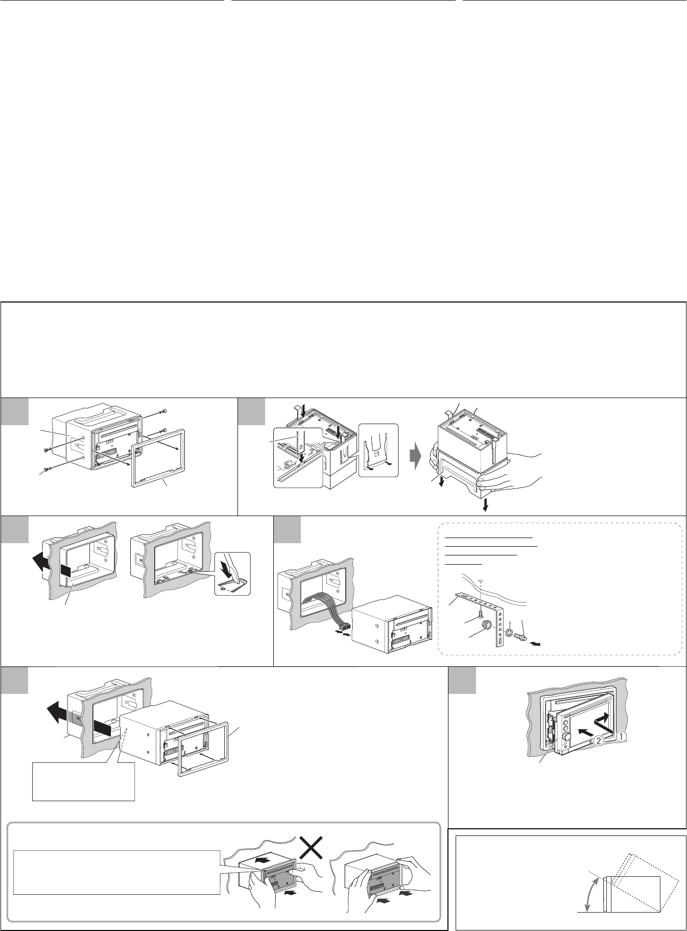
INSTALLATION
(IN-DASH MOUNTING)
The following illustration shows a typical installation. However, you
should make adjustments corresponding to your specific car. If you
have any questions or require information regarding installation kits,
consult your JVC IN-CAR ENTERTAINMENT dealer or a company
supplying kits.
• If you are not sure how to install this unit correctly, have it installed
by a qualified technician.
Before installing the unit
• Remove the audio system originally installed in the car, together
with its mounting brackets. Be sure to keep all the screws and parts
removed from your car for future use.
• When mounting the unit, be sure to use the screws provided, as
instructed. If other screws are used, parts could become loose or
damaged.
• When tightening screws or bolts, be careful not to pinch any
connection cord.
• Make sure not to block the fan on the rear to maintain proper
ventilation when installing the unit.
When installing the unit without using the sleeve
• Use flat head screws or round head screws, depending on the
mounting bracket. When you use flat head screws to install the unit,
use the screws removed in step 1 below. When you use screws other
than those supplied, use 8 mm-long screws. If longer screws are
used, they could damage the unit.
• Tighten the screws firmly to prevent the unit from falling off.
1 Detach the trim plate and remove the screws.
2 Detach the sleeve using the handles then slide off the sleeve.
3 Install the sleeve in the dashboard of the car.
4 Do the required electrical connections.
• See pages 3 – 6.
5 Attach the trim plate to the main unit, then install the main unit
in to the sleeve.
6 Attach the monitor panel.
Install the unit at an angle of less
than 30.
Instale la unidad a un ángulo de
menos de 30.
Установите устройство под
углом менее 30°.
УСТАНОВКА (УСТАНОВКА В
ПРИБОРНУЮ ПАНЕЛЬ)
На следующих иллюстрациях показана типовая установка. Однако
необходимо выполнить настройки, соответствующие конкретному
автомобилю. Если у Вас есть какие-либо вопросы, касающиеся
установки, обратитесь к Вашему дилеру автомобильных систем JVC
или в компанию, поставляющую соответствующие принадлежности.
• Если Вы не знаете точно, как следует устанавливать это
устройство, обратитесь к квалифицированному специалисту.
• Извлеките аудиосистему, изначально установленную в
автомобиле, вместе с монтажными кронштейнами. Не теряйте
винты и детали, извлеченные из автомобиля, поскольку они
будут использоваться в дальнейшем.
• При установке устройства используйте только прилагаемые
болты в соответствии с инструкцией. В случае использования
других болтов существует вероятность, что детали могут быть
ненадежно закреплены или повреждены.
• Аккуратно затягивайте болты,чтобы не пережать
соединительные кабели.
• При установке для обеспечения правильной вентиляции не
закрывайте вентилятор на задней панели.
• Используйте болты с плоской головкой или болты с
круглой головкой, в зависимости от места установки. Если
при установке устройства используются болты с плоской
головкой, используйте болты, извлеченные в действии 1.
Если используются болты, не входящие в комплект поставки,
используйте болты длиной 8 мм. При использовании более
длинных болтов можно повредить устройство.
• Надежно затяните винты, чтобы предотвратить выпадение
устройства.
1 Отсоедините декоративную панель и извлеките болты.
2 Отсоедините муфту с помощью рукояток, а затем сдвиньте
муфту, чтобы снять ее.
3 Вмонтируйте муфту в приборную панель автомобиля.
4 Выполните необходимые электрические соединения.
• См. стр. 3 – 6.
5 Подсоедините декоративную панель к главному устройству,
а затем установите главное устройство в муфту.
6 Подключите панель монитора.
INSTALACIÓN (MONTAJE EN EL
TABLERO DE INSTRUMENTOS)
La siguiente ilustración muestra una instalación típica. Sin embargo
usted deberá efectuar los ajustes correspondientes a su automóvil.
Si tiene alguna pregunta o necesita información acerca de las
herramientas para instalación, consulte con su concesionario de JVC de
equipos de audio para automóviles o a una compañía que suministra
tales herramientas.
• Si no está seguro de poder instalar la unidad correctamente, déjela en
manos de un técnico cualificado.
Antes de instalar la unidad
• Desmonte el sistema de audio instalado originalmente en el coche,
junto con los ménsulas de montaje. Asegúrese de guardar todos los
tornillos y piezas quitados de su vehículo para poderlos usar en el
futuro.
• Al instalar la unidad, asegúrese de usar los tornillos suministrados,
de acuerdo con las instrucciones. El uso de otros tornillos podrá
provocar flojedad de o daños a las piezas.
• Al apretar los tornillos o los pernos, asegúrese de que ningún cable de
conexión quede pillado.
• Al efectuar la instalación, asegúrese de no bloquear el ventilador del
panel trasero a fin de mantener una ventilación correcta.
Instalación de la unidad sin utilizar la cubierta
• Utilice tornillos de cabeza plana o esférica, dependiendo del lugar de
instalación. Si decide utilizar tornillos de cabeza plana para instalar la
unidad, utilice los extraídos en el paso 1, más abajo. Si decide utilizar
tornillos distintos de los suministrados, escoja tornillos de 8 mm de
largo. El uso de tornillos más largos producir daños a la unidad.
• Apriete los tornillos firmemente para evitar que la unidad se caiga.
1 Desmonte la placa de guarnición y extraiga los tornillos.
2 Sujetando las asas, desmonte la cubierta deslizándola.
3 Instale la cubierta en el tablero del automóvil.
4 Realice todas las conexiones eléctricas necesarias.
• Consulte las páginas 3 – 6.
5 Fije la placa de guarnición a la unidad principal y, a continuación,
instale ésta en la cubierta.
6 Fije el panel del monitor.
Sleeve
Cubierta
Муфта
Monitor panel
Panel del monitor
Панель монитора
Trim plate
Placa de guarnición
Декоративную панель
When you stand the unit, be careful not to
damage the fuse on the rear.
Al poner la unidad vertical, tenga cuidado
de no dañar el fusible provisto en la parte
posterior.
Устанавливайте устройство таким
образом, чтобы не повредить
предохранитель, расположенный сзади.
Handles
Manijas
Рычаги
Sleeve
Cubierta
Муфта
Trim plate
Placa de guarnición
Декоративную панель
Sleeve
Cubierta
Муфта
Flat head screws (M5 × 8 mm)
Tornillos de cabeza plana (M5 × 8 mm)
Болты с плоской головкой (M5 × 8 мм)
Bend the appropriate tabs to hold the sleeve firmly in place.
Doble las lengüetas apropiadas para retener firmemente
la manga en su lugar.
Отогните соответствующие фиксаторы,
предназначенные для прочной установки корпуса.
Do not block the fan.
No tape las rejillas de ventilación.
Не закрывайте вентилятор.
Slide the unit in until you hear a clicking sound.
Deslice la unidad hasta escuchar un chasquido.
Задвиньте устройство внутрь до щелчка.
Sleeve
Cubierta
Муфта
For more stable attachment
Para una fijación más estable
Для более прочного
крепления
A
Stay (option) /
Soporte (opción)
/
Стойка (дополнительно)
B Screw (option) / Tornillo (opción) /
Винт (дополнительно)
C Lock nut / Tuerca de seguridad /
Фиксирующая гайка
D Washer / Arandela /Шайба
E
Mounting bolt /
Perno de montaje
/
Крепежный болт
To the rear panel / Al panel trasero /
К задней панели
30˚
DO NOT press the panel (shaded in the illustration).
NO presione el panel (sombreado en la ilustración).
НЕ нажимайте на панель (затемнена на рисунке).
O
K
Install_KW-NSX1[EU].indb 2Install_KW-NSX1[EU].indb 2 12/04/21 16:4912/04/21 16:49
1 2 3
3
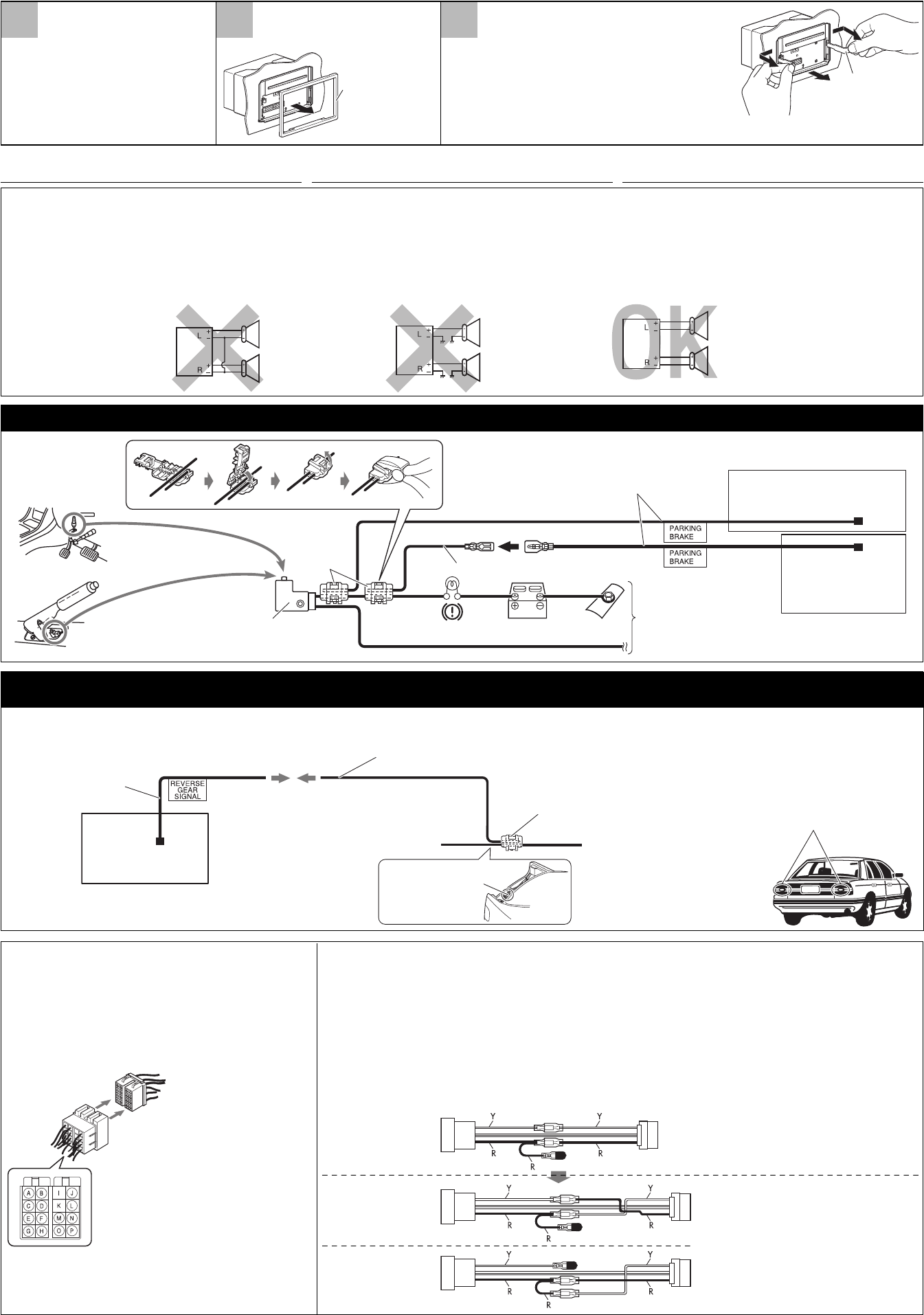
ELECTRICAL CONNECTIONS
PRECAUTIONS on power supply and speaker connections:
• DO NOT connect the speaker leads of the power cord A
to the car battery; otherwise, the unit will be seriously
damaged.
• BEFORE connecting the speaker leads of the power cord A to the
speakers, check the speaker wiring in your car.
ЭЛЕКТРИЧЕСКИЕ ПОДКЛЮЧЕНИЯ
:
•
,
.
• ПЕРЕД подключением проводов громкоговорителей
к кабелю питания громкоговорителя проверьте схему
соединений громкоговорителей в Вашем автомобиле.
Connecting the parking brake lead / Conexión del cable del freno de estacionamiento /
Locate the reverse lamp lead in the trunk.
Extension lead (not supplied for this unit) / Cable prolongador (no suministrado con esta unidad) /
Удлинитель (не входит в комплект поставки)
Reverse gear signal lead (Purple
with white stripe)
Cable de señal del engranaje de
marcha atrás (Púrpura con rayas
blancas)
Провод сигнала передачи
заднего хода (Фиолетовый с
белой полосой)
Reverse lamps
Lámparas de marcha atrás
Задние фары
To reverse lamp
A la luz de marcha atrás
К задней фаре
Reverse lamp lead
Conductor de la luz de
marcha atrás
Провод задней фары
Найдите лампу заднего хода в ящике.
Connecting the reverse gear signal lead (for rear view camera) / Conexión del cable de señal del engranaje de marcha atrás (para cámara de
retrovisión) / ( )
PRECAUCIONES sobre las conexiones de la fuente de
alimentación y de los altavoces:
• NO conecte los conductores de altavoz del cable de
alimentación A a la batería de automóvil, pues podrían
producirse graves daños en la unidad.
• ANTES de conectar a los altavoces los conductores de altavoz del
cable de alimentación A, verifique el conexionado de altavoz de su
automóvil.
CONEXIONES ELECTRICAS
If your car is equipped with the ISO connector
Si su automóvil está equipado con el conector ISO
ISO
• Connect the ISO connectors as illustrated.
• Conecte los conectores ISO tal como se indica en la ilustración.
• Подключите разъемы ISO, как показано на рисунке.
From the car body
Desde la carrocería del vehículo
От корпуса автомобиля
ISO connector of the supplied power cord
Conector ISO del cable de alimentación
suministrado
Разъем ISO шнура питания, входящего в
комплект поставки
View from the lead side
Vista desde el lado del conductor
Вид со стороны выводов
For some VW/Audi or Opel (Vauxhall) automobiles / Para algunos automóviles VW/Audi u Opel
(Vauxhall) / VW/Audi Opel (Vauxhall)
You may need to modify the wiring of the supplied power cord as illustrated.
• Contact your authorized car dealer before installing this unit.
Podría ser necesario modificar el conexionado del cable de alimentación suministrado, tal como se indica en la ilustración.
• Antes de instalar esta unidad, consulte a su concesionario de automóviles autorizado.
Возможно, потребуется изменить схему соединений для прилагаемого шнура питания, как показано на рисунке.
• Перед установкой приемника обратитесь к авторизованному агенту по продажам автомобильных систем.
Y: Yellow
Amarillo
Желтый
R: Red
Rojo
Красный
Original wiring
Conexionado original
Исходная схема
соединений
Modified wiring 1
Conexionado modificado 1
Преобразованная схема
соединений 1
Modified wiring 2
Conexionado modificado 2
Преобразованная схема
соединений 2
Use modified wiring 2 if the unit does not turn on.
Si la unidad no se enciende, utilice el conexionado
modificado 2.
Если приемник не включается, используйте
преобразованную схему соединений 2.
Parking brake
Freno de estacionamiento
Стояночный тормоз
Parking brake switch (inside the car)
Interruptor del freno de estacionamiento (dentro del automóvil)
Переключатель стояночного тормоза (внутри автомобиля)
Parking brake lead (light green)
Cable del freno de estacionamiento (verde claro)
Провод стояночного тормоза (зеленого цвета)
To metallic body or chassis of the car
A un cuerpo metálico o chasis del
automóvil
К металлическому корпусу или
шасси автомобиля
Crimp connector
Conector de sujeción
Обжимные
разъемы
Localice el cable de la lámpara de marcha atrás en el baúl.
Crimp connector
Conector de sujeción
Обжимные разъемы
Removing the unit
Before removing the unit, release the rear section.
Extracción de la unidad
Antes de extraer la unidad, libere la sección trasera.
Перед удалением устройства освободите заднюю часть.
Trim plate
Placa de guarnición
Декоративную
панель
Detach the monitor panel (see page 5
of the INSTRUCTIONS).
Desmonte el panel del monitor
(consulte la página 5 del MANUAL DE
INSTRUCCIONES).
Отсоедините панель монитора
(см. стр. 5 ИНСТРУКЦИИ ПО
ЭКСПЛУАТАЦИИ).
Insert the two handles, then pull them as illustrated so that
the unit can be removed.
Inserte las dos manijas y, a continuación, jálelas tal como se
muestra en la ilustración para desmontar la unidad.
Вставьте две рукоятки, затем потяните их на себя, как это
показано на рисунке, таким образом, чтобы можно было
снять устройство. Handles
Manijas
Рычаги
Detach the trim plate.
Desmonte la placa de guarnición.
Отсоедините декоративную панель.
Parking brake extension lead
Cable prolongador del freno de estacionamiento
Удлинительный провод стояночного тормоза
Main unit
Unidad principal
Main unit
Unidad principal
Smartphone Adapter unit
Adaptador Smartphone
Install_KW-NSX1[EU].indb 3Install_KW-NSX1[EU].indb 3 12/04/21 16:4912/04/21 16:49

PARKING BRAKE
REVERSE
GEAR
SIGNAL
SUBWOOFER
OUT
DIRECT STEERING REMOTE
*1
*1
(STEERING WHEEL REMOTE)
(REMOTE OUTPUT ONLY)
4
ENGLISH
Before connecting: Check the wiring in the vehicle carefully.
Incorrect connection may cause serious damage to this unit.
The leads of the power cord A and those of the connector from the
car body may be different in color.
1 Cut the ISO connector.
2 Connect the colored leads of the power cord A in the order
specified in the illustration below.
3 Connect the aerial cord.
4 Finally connect the wiring harness to the unit.
• The terminals and cables of all models are shown in the illustration
for the purpose of explanation.
Connections without using the ISO connectors / Conexión sin usar el conector ISO / ISO
10 A fuse / Fusible de 10 A / Предохранитель 10 A
Fan / Ventilador / Вентилятор
To parking brake (see page 3)
Al freno de estacionamiento (consulte la
página 3)
К стояночному тормозу (cм. стр. 3)
Rear ground terminal
Terminal de tierra posterior
Задний разъем заземления
(see page 3 / consulte la página 3 / cм. стр. 3)
: Тщательно проверьте
проводку в автомобиле. Неправильное подключение может
привести к серьезному повреждению устройства. Жилы
силового кабеля A и жилы соединителя от кузова автомобиля
могут быть разного цвета.
1 Обрежьте разъем ISO.
2 Подсоедините цветные провода шнура питания A в
указанном ниже порядке.
3 Подключите кабель антенны.
4
В последнюю очередь подключите электропроводку к устройству.
• Контактные разъемы и кабели всех моделей приведены на
рисунке с целью объяснения.
Aerial terminal
Terminal de la antena
Разъем антенны
*1 Not supplied for this unit.
*2 Before checking the operation of this unit prior to installation, this lead
must be connected, otherwise power cannot be turned on.
Do not connect the lead directly to the battery.
*3 Do not connect the lead to any device other than the OE remote
adapter. Doing so may cause malfunction.
*1 Hе входит в комплект поставки.
*2 Перед проверкой работы устройства подключите этот провод,
иначе питание не включится.
Не подсоединяйте провод напрямую к аккумуляторной батарее.
*3 Не подсоединяйте провод ни к какому другому устройству,
кроме адаптера дистанционного управления OE. Это может
привести к неполадке.
РУCCKИЙ ESPAÑOL
Antes de la conexión: Verifique atentamente el conexionado del
vehículo. Una conexión incorrecta podría producir daños graves en la
unidad. Los cordones del cable de alimentación A y los del conector
procedentes de la carrocería del automóvil podrían ser de diferentes en
color.
1 Corte el connector ISO.
2 Conecte los conductores de color del cable de alimentación A en el
orden especificado en la ilustración de abajo.
3 Conecte el cable de antena.
4 Por último, conecte el cable de alimentación a la unidad.
• Los terminales y cables de todos los modelos se muestran en la
ilustración con fines explicativos.
To metallic body or chassis of the car
A un cuerpo metálico o chasis del automóvil
К металлическому корпусу или шасси автомобиля
To a live terminal in the fuse block connecting to the car battery
(bypassing the ignition switch) (constant 12 V)
A un terminal activo del bloque de fusibles conectado a la batería del automóvil
(desviando el interruptor de encendido) (12 V constantes)
К разъему фазы в блоке предохранителя (минуя блок зажигания)
(постоянный 12 В)
To an accessory terminal in the fuse block
A un terminal accesorio del bloque de fusibles
К вспомогательному разъему в блоке
предохранителя
Black
Negro
Черный
Yellow
*
2
Amarillo *2
Желтый
*
2
Red
Rojo
Красный
Ignition switch
Interruptor de encendido
Переключатель зажигания
Fuse block
Bloque de fusibles
Блок
предохранителя
Power cord A
Cordón de alimentación A
Шнур питания A
ISO connector
Conector ISO
Разъем ISO
Orange with white stripe
Naranja con rayas blancas
Оранжевый с белой полосой To car light control switch
Al interruptor de control de las luces del automóvil
К контрольному переключателю освещения автомобиля
Brown
Marrón
Коричневый Not used
No utilizado
Не используется
Blue with white stripe
Azul con rayas blancas
Синий с белой полосой
Crimp connector
Conector de sujeción
Обжимные разъемы
White with black stripe
Blanco con rayas negras
Белый с черной полосой
White
Blanco
Белый
Gray with black stripe
Gris con rayas negras
Серый с черной
полосой
Gray
Gris
Серый
Green with black stripe
Verde con rayas negras
Зеленый с черной полосой
Green
Verde
Зеленый
Purple with black stripe
Púrpura con rayas negras
Пурпурный с черной
полосой
Purple
Púrpura
Пурпурный
Left speaker (front)
Altavoz izquierdo (delantero)
Левый громкоговоритель
(передний)
Right speaker (front)
Altavoz derecho (delantero)
Правый громкоговоритель
(передний)
Left speaker (rear)
Altavoz izquierdo (trasero)
Левый громкоговоритель
(задний)
Right speaker (rear)
Altavoz derecho (trasero)
Правый громкоговоритель
(задний)
*1 No suministrado con esta unidad.
*2 Antes de comprobar el funcionamiento de esta unidad previa a de la
instalación, es necesario conectar este cable, de lo contrario no se podrá
conectar la alimentación.
No conecte el conductor directamente a la batería.
*3 No conecte el cable a ningún otro dispositivo que no sea el adaptador
para control remoto OE. De lo contrario podría provocar un mal
funcionamiento.
To the Smartphone Adapter unit (REMOTE IN)
Al adaptador Smartphone (REMOTE IN)
К адаптеру для смартфона (REMOTE IN)
See each diagram on pages 5 and 6.
Vea cada uno de los diagramas en las páginas 5 y 6.
См. каждую схему на стр. 5 и 6.
To the OE remote adapter *3
Al adaptador para control remoto OE *3
К адаптеру дистанционного управления OE *3
Light green / Verde claro / Зеленого цвета
Blue with yellow stripe
Azul con rayas amarillas
Синий с желтой полосой
Not used / No utilizado / Не используется
Parking brake extension lead
Cable prolongador del freno de estacionamiento
Удлинительный провод стояночного тормоза
Install_KW-NSX1[EU].indb 4Install_KW-NSX1[EU].indb 4 12/04/21 16:4912/04/21 16:49
*6
*7*7
5
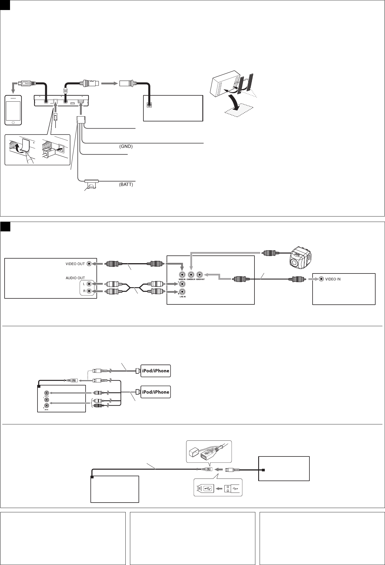
Connecting the external components / Conexión de otros componentes externos /
USB cable (approx. 1 m)
Cable USB (aprox. 1 m)
Кабель USB (прибл. 1 м) USB device
Dispositivo USB
USB
Connecting the iPod or the iPhone / Conexión del iPod o iPhone / iPod iPhone
USB devices / Dispositivos USB / USB
KS-U30 (not supplied /
no suministrado / не поставляются)
USB 2.0 cable (accessory of the iPod/iPhone)
Cable USB 2.0 (accesorio del iPod/iPhone)
Кабель USB 2.0 (принадлежность iPod/iPhone)
B
• To watch video, connect the iPod/iPhone using JVC KS-U30 *8 (separately purchased), otherwise,
video is not displayed on the screen.
• To listen to music, connect the iPod/iPhone using a USB 2.0 cable (accessory of the iPod/iPhone).
• Para ver video, conecte el iPod/iPhone mediante el JVC KS-U30 *8 (en venta por separado); de lo
contrario, no aparecerá video en la pantalla.
• Para escuchar música, conecte el iPod/iPhone mediante un cable USB 2.0 (accesorio del iPod/iPhone).
• подключите iPod/iPhone с помощью JVC KS-U30 *8 (продается
отдельно), в противном случае видеоматериалы не будут отображаться на экране.
• подсоедините iPod/iPhone с помощью кабеля USB 2.0
(принадлежность iPod/iPhone).
Camcorder, etc.
Videocámara, etc.
Портативная
видеокамера, и т.д. External monitor
Monitor externo
KV-CM10/KV-CM20 *5
Rear view camera
Cámara de retrovisión
Камера заднего вида
*4 Before checking the operation of this unit prior to installation, this lead
must be connected, otherwise power cannot be turned on.
Do not connect the lead directly to the battery.
*5 Not supplied for this unit.
*6 Audio cord (not supplied for this unit).
*7 Video cord (not supplied for this unit).
*8 When using the cable, you need to change the setting on the unit (see
page 27 of the INSTRUCTIONS).
*4 Перед проверкой работы устройства подключите этот провод,
иначе питание не включится.
Не подсоединяйте провод напрямую к аккумуляторной батарее.
*5 Hе входит в комплект поставки.
*6 Аудиошнур (не входит в комплект поставки).
*7 Видеокабели (не входит в комплект поставки).
*8 Если используется этот кабель, необходимо изменить настройку
на устройстве (см. стр. 27 ИНСТРУКЦИИ ПО ЭКСПЛУАТАЦИИ).
*4 Antes de comprobar el funcionamiento de esta unidad previa a de la
instalación, es necesario conectar este cable, de lo contrario no se podrá
conectar la alimentación.
No conecte el conductor directamente a la batería.
*5 No suministrado con esta unidad.
*6 Cable de audio (no suministrado con esta unidad).
*7 Cables de video (no suministrado con esta unidad).
*8 Cuando utilice el cable, deberá cambiar el ajuste en la unidad (consulte la
página 27 del MANUAL DE INSTRUCCIONES).
AConnecting the Smartphone Adapter unit / Conexión del ADAPTADOR SMARTPHONE /
(REMOTE IN)
(PARKING BRAKE)
Main unit
Unidad principal
Main unit
Unidad principal
Yellow
*
4
Amarillo *4
Желтый
*
4
Smartphone
Smartphone
Смартфон
Smartphone Adapter unit
Adaptador Smartphone
Адаптер для смартфона
Light green / Verde claro /
Зеленого цвета
Power cord B
Cable de alimentación B
Шнур питания B
Black / Negro / Черный
Main unit
Unidad
principal
Main unit
Unidad principal
Micro-B USB connection
Conexión USB Micro-B
Соединение через интерфейс USB типа Micro-B
5 A fuse / Fusible de 5 A / Предохранитель 5 A
Blue with white stripe
Azul con rayas blancas
Синий с белой полосой
To a live terminal in the fuse block connecting to the car battery
(bypassing the ignition switch) (constant 12 V)
A un terminal activo del bloque de fusibles conectado a la
batería del automóvil (desviando el interruptor de encendido)
(12 V constantes)
К разъему фазы в блоке предохранителя (минуя блок
зажигания) (постоянный 12 В)
To metallic body or chassis of
the car
A un cuerpo metálico o chasis
del automóvil
К металлическому корпусу
или шасси автомобиля
To the main unit (REMOTE OUTPUT ONLY)
A la unidad principal (REMOTE OUTPUT
ONLY)
К главному устройству (REMOTE OUTPUT
ONLY)
Remove the backing from the hook and loop fastener and attach it to
the bottom of the unit. Install the Smartphone Adapter unit on the
carpet.
• Do not install the unit near the dashboard, the rear tray, or other
important components. Doing so could lead to injury or accident.
Retire el respaldo del cierre de gancho y bucle y fíjelo a la parte inferior
de la unidad. Instale el adaptador Smartphone sobre la alfombra.
• No instale la unidad cerca del tablero de instrumentos, la bandeja
trasera u otros componentes importantes. De hacerlo, podrían
producirse lesiones o accidentes.
Снимите задник с застежки типа крюк-петля и прикрепите
к днищу устройства. Установите адаптер для смартфона на
коврик.
• Не устанавливайте устройство вблизи приборной панели,
задней полки или других важных компонентов. Это может
привести к травме или несчастному случаю.
Hook and loop fastener
Cierre de gancho y bucle
Застежка типа крюк-петля
Carpet
Alfombra
Коврик
Connect the Smartphone Adapter unit to the RGB input terminal. If
you connect your smartphone to the Smartphone Adapter unit via
USB, you can view the smartphone screen.
• If the smartphone cannot receive GPS signals, connect a GPS
antenna (KV-GP10: separately purchased) to the Smartphone
Adapter unit, so that it can be used as the antenna for smartphone.
• The firmware of the Smartphone Adapter unit may be updated.
Install the Smartphone Adapter unit in a position where it can be
pulled out easily.
GPS antenna input
La antena GPS de
entrada
GPS антенный
вход
RGB input terminal
Terminal de entrada RGB
Вход RGB
To parking brake (see page 3)
Al freno de estacionamiento (consulte la página 3)
К стояночному тормозу (cм. стр. 3)
Conecte el ADAPTADOR SMARTPHONE al terminal de entrada
RGB. Conectando su Smartphone al ADAPTADOR SMARTPHONE a
través de USB podrá ver la pantalla del Smartphone.
• Si el Smartphone no puede recibir señales GPS, conecte una
antena GPS (KV-GP10: adquirido por separado) al ADAPTADOR
SMARTPHONE, de manera que pueda utilizarse como antena del
Smartphone.
• El firmware del adaptador Smartphone puede ser actualizado. Instale
el adaptador Smartphone en una posición que facilite su extracción.
Подключите АДАПТЕР ДЛЯ СМАРТФОНА к входному разъему
RGB. Если вы подключите смартфон к АДАПТЕРУ ДЛЯ
СМАРТФОНА через интерфейс USB, то вы сможете увидеть
экран смартфона.
• Если смартфон не может принимать сигналы GPS,
подсоедините антенну GPS (KV-GP10: приобретается
отдельно) к АДАПТЕРУ ДЛЯ СМАРТФОНА, чтобы ее можно
было использовать в качестве антенны для смартфона.
• Встроенное программное обеспечения адаптера для
смартфона можно обновлять. Устанавливайте адаптер для
смартфона в таком положении, чтобы его можно было легко
извлечь.
Install_KW-NSX1[EU].indb 5Install_KW-NSX1[EU].indb 5 12/04/21 16:4912/04/21 16:49

STEERING
WHEEL
REMOTE
6
*9 Not supplied for this unit.
*10 Audio cord (not supplied for this unit).
*11 Firmly attach the ground wire to the metallic body or to the chassis of
the car—to the place uncoated with paint (if coated with paint, remove
the paint before attaching the wire). Failure to do so may cause damage
to the unit.
*12 Alter the wire of the OE remote adapter to connect to the steering wheel
remote lead.
*9 Hе входит в комплект поставки.
*10 Аудиошнур (не входит в комплект поставки).
*11 Плотно прикрепите заземляющий провод к металлическому
кузову или шасси автомобиля—в месте, не покрытом краской
(если оно покрыто краской, удалите краску перед тем, как
прикреплять провод). Невыполнение этого требования может
привести к повреждению данного устройства.
*12 Смените провод адаптера дистанционного управления OE для
подсоединения к проводу рулевого пульта дистанционного
управления.
TROUBLESHOOTING
• The fuse blows.
* Are the red and black leads connected correctly?
• Power cannot be turned on.
* Is the yellow lead connected?
• No sound from the speakers.
* Is the speaker output lead short-circuited?
• Sound is distorted.
* Is the speaker output lead grounded?
* Are the “–” terminals of L and R speakers grounded in common?
• Noise interfere with sounds.
* Is the rear ground terminal connected to the car’s chassis using
shorter and thicker cords?
• This unit becomes hot.
* Is the speaker output lead grounded?
* Are the “–” terminals of L and R speakers grounded in common?
• This unit does not work at all.
* Have you reset your unit?
BЫЯВЛЕНИЕ НЕИСПРАВНОСТЕЙ
• .
* Правильно ли подключены черный и красный провода?
• .
* Подключен ли желтый провод?
• .
* Нет ли короткого замыкания на кабеле выхода
громкоговорителей?
• .
* Заземлен ли провод выхода громкоговорителей?
* Заземлены ли разъемы “–” правого (R) и левого (L)
громкоговорителей?
• .
* Соединен ли находящийся сзади зажим заземления с шасси
автомобиля с помощью более короткого и тонкого шнуров?
• .
* Заземлен ли провод выхода громкоговорителей?
* Заземлены ли разъемы “–” правого (R) и левого (L)
громкоговорителей?
• .
* Выполнена ли перенастройка приемника?
*9 No suministrado con esta unidad.
*10 Cable de audio (no suministrado con esta unidad).
*11 Fije firmemente el cable de tierra a un cuerpo metálico o chasis del
automóvil—a un lugar no cubierto con pintura (si está cubierto con
pintura, quítela antes de fijar el cable). De lo contrario, se podrían
producir daños en la unidad.
*12 Altere el cableado del adaptador para control remoto OE para conectar al
conductor remoto del volante de dirección.
LOCALIZACIÓN DE AVERIAS
• El fusible se quema.
* ¿Están los conductores rojo y negro correctamente conectados?
• No es posible conectar la alimentación.
* ¿Está el cable amarillo conectado?
• No sale sonido de los altavoces.
* ¿Está el cable de salida del altavoz cortocircuitado?
• El sonido presenta distorsión.
* ¿Está el cable de salida del altavoz conectado a masa?
* ¿Están los terminales “–” de los altavoces L y R conectados a una
masa común?
• Perturbación de ruido.
* ¿El terminal de tierra trasero está conectado al chasis del automóvil
utilizando los cordones más corto y más grueso?
• La unidad se calienta.
* ¿Está el cable de salida del altavoz conectado a masa?
* ¿Están los terminales “–” de los altavoces L y R conectados a una
masa común?
• Este receptor no funciona en absoluto.
* ¿Reinicializó el receptor?
Connecting to the steering wheel remote controller / Conexión del control remoto del volante de dirección /
If your car is equipped with the steering wheel remote controller,
you can operate this unit using the controller. To do it, a JVC’s
OE remote adapter (not supplied) which matches with your car is
required. Consult your JVC IN-CAR ENTERTAINMENT dealer for
details.
E
Si su vehículo está equipado con control remoto en el volante de
dirección, podrá hacer funcionar este receptor utilizando dicho control.
Para ello, se requiere un adaptador para control remoto OE de JVC
(no suministrado) que corresponda con su vehículo. Para mayor
información, consulte con su concesionario car audio de JVC.
Если автомобиль оборудован рулевым пультом
дистанционного управления, его можно использовать для
управления данным устройством. Для этого необходим
адаптер рулевого пульта дистанционного управления JVC
OE (не поставляется), подходящий для Вашего автомобиля.
За более подробной информацией обратитесь к поставщику
автомобильных аудиосистем компании JVC.
Connecting the microphone / Conexión de la unidad de micrófono /
C
Secure the microphone cord using cord cramps (not
supplied) if necessary.
Si es necesario, asegure el cable del micrófono por
medio de abrazaderas (no suministradas).
При необходимости закрепите кабель
микрофона с помощью зажимов для кабеля (не
поставляются).
Adhesive tape
Cinta adhesiva
Липкая лента
Microphone
Micrófono
Микрофон
OE remote adapter *9 *12 / Adaptador para control remoto OE *9 *12 /
Aдаптер рулевого пульта дистанционного управления OE *9 *12 Steering wheel remote controller (equipped in
the car)
Control remoto del volante de dirección (equipado
en el vehículo)
Рулевой пульт дистанционного управления
(устанавливаемый в автомобиле)
12 3
Main unit
Unidad principal
Main unit
Unidad principal
*10
*10 *10
*11 *11
*11
Connecting the external amplifiers and subwoofer / Conexión del amplificador y subwoofer externo /
You can connect an amplifier to upgrade your car stereo system.
• Connect the remote lead (blue with white stripe) to the remote
lead of the other equipment so that it can be controlled through
this unit.
• Disconnect the speakers from this unit, and connect them to
the amplifier. Leave the speaker leads of this unit unused.
• You can switch off the built-in amplifier and send the audio
signals only to the external amplifier(s) to get clear sounds and to
prevent internal heat built-up inside the unit. See page 44 of the
INSTRUCTIONS.
Remote lead *9
Cable remoto *9
Провод внешнего
устройства *9
Можно подключить усилители для обновления автомобильной
стереосистемы.
•
Подсоедините провод внешнего устройства (синий с белой
полосой) к проводу внешнего устройства другого оборудования
так, чтобы им можно было управлять с этого устройства.
•
, .
.
• Для получения более чистого звука и предотвращения
внутреннего перегрева приемника можно отключить
встроенный усилитель и использовать для усиления
аудиосигнала только внешние усилители. Cм. ИНСТРУКЦИИ
ПО ЭКСПЛУАТАЦИИ на стр. 44.
Usted podrá conectar un amplificador para mejorar el sistema estéreo
de su automóvil.
• Conecte el conductor remoto (azul con rayas blancas) al conductor
remoto del otro equipo para poderlo controlar a través de esta
unidad.
• Desconecte los altavoces de esta unidad y conéctelos al
amplificador. Los cables de los altavoces de esta unidad
quedan sin usar.
• Podrá desconectar el amplificador incorporado y enviar las señales
de audio solamente al(los) amplificador(es) externo(s) para obtener
sonidos nítidos y evitar que se caliente el interior de la unidad.
Consulte la página 44 del MANUAL DE INSTRUCCIONES.
JVC Amplifier
Amplificador de JVC
JVC-
Subwoofer
Subwoofer
Низкочастотный
динамик
Rear speakers
Altavoces traseros
Задние
громкоговорители
Front speakers
Altavoces delanteros
Передние
громкоговорители
To the remote lead of other equipment or power aerial if any
Al conductor remoto de otro equipo o de la antena automática, si hubiere
К удаленному проводу другого оборудования или антенны
Remote lead (blue with white stripe)
Cable remoto (azul con rayas blancas)
Провод внешнего устройства
(синий с белой полосой)
Y-connector *9 / Conector en Y *9
Разъем Y *9
JVC Amplifier
Amplificador de JVC
JVC-
JVC Amplifier
Amplificador de JVC
JVC-
D
Main unit
Unidad principal
Install_KW-NSX1[EU].indb 6Install_KW-NSX1[EU].indb 6 12/04/21 16:4912/04/21 16:49
