Jiaxing ShuFuDe Electric Bed 900SPEAKER BT SPEAKER User Manual Manual
Jiaxing Shufude Electric Bed CO.,LTD BT SPEAKER Manual
UserManual.wiki
>
Jiaxing ShuFuDe Electric Bed
>
900SPEAKER User Manual
Manual.pdf
Navigation menu
Upload a User Manual
Namespaces
Wiki Guide
HTML
PDF
Info
Views
User Manual
Discussion / Help
Navigation

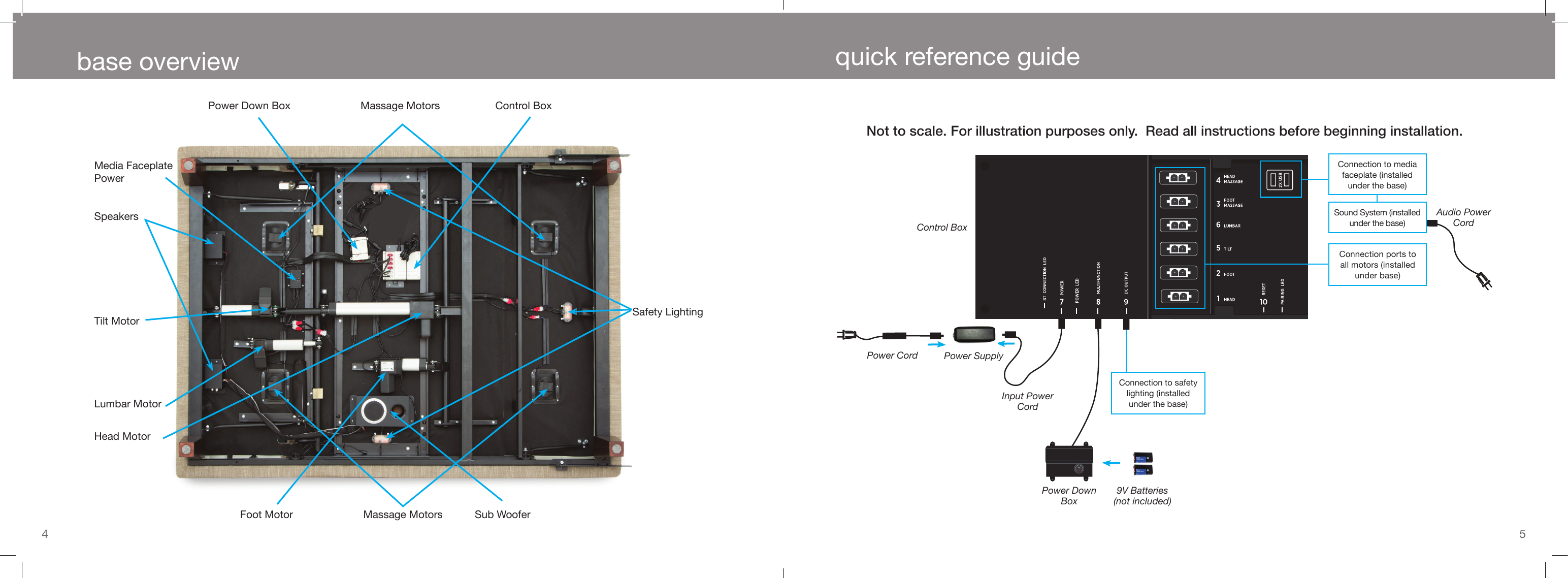
![2 3safety precautions and usage statements parts listAll electronics and components that need to be installed are located in boxes under the base or attached to the frame.A) Wireless Remote Control and (3) AAA batteriesB) Mattress Retainer Bar (1)*C) Legs (4)D) Power Cord (1)E) Power Supply (1)F) Power Down Box (1)* G) Connecting Strap*‡H) SmartSync™ Cord (1) ‡I) Audio Power Cord (1)*Headboard Bracket Components:J) Headboard Bracket (2)K) T-Bracket (2) L) Spacers (2)M) Long Bolts (8)N) Short Bolts (10)O) Nuts (18)Misc Parts (not included):P) Surge ProtectorQ) 9 Volt Batteries (2)* These items are attached to the base for shipping purposes. Carefully remove from base and set aside.‡ Only included in Twin, Twin Long, Queen Split and Cal King Split bases.Before discarding the packing materials- ensure all the parts are accounted for.FCC Compliance:This device complies with part 15 of the FCC Rules. Operation is subject to the following two conditions: (1) This device may not cause harmful interference, and (2) this device must accept any interference received, including interference that may cause undesired operation. To comply with the FCC RF exposure requirements, no change to the antenna or the device is permitted. Any change to the antenna or the device could result in the device exceeding the RF exposure requirement and void user’s right to operate the device.Radio Frequency: 2.4 GHzPets and Small Children:Immediately dispose of all packing materials as it may pose a smothering risk to small children and pets. To avoid injury, it is not advised to allow children and small pets to play on or under the bed. Children should not operate the bed base without adult supervision.Safety Features: Casters (optional leg accessory) are equipped with locking wheels to prevent unwanted movement. Even when locked and unable to roll, it is possible for the casters to slide. Free release head and foot motors are designed to lower the mattress by retracting only with gravity, never pulling downwards, which minimizes pinch points.Product Ratings:The lift motors are not designed to operate continuously for more than [2] minutes in an [18] minute time period or approximately 10% duty cycle. Attempting to circumvent or exceed this rating will shorten the life expectancy of the product and may void the warranty.Weight Limits:This product is not rated to support weights exceeding 850 pounds. This product is not rated to support weights in excess of 850 pounds inclusive of the mattress and bedding. The base will structurally support this weight, provided it is evenly distributed across the bed base. The adjustable base is not designed to support or lift this amount in the head or foot sections alone. Exceeding this weight restriction could damage the bed and/or cause injury and will void the warranty. Acoustics:The massage function will emit a noticeable tone during operation. As the massage intensity level is increased, the tone will intensify. The volume of this tone is directly related to the location environment. For example, when demonstrated in a show room, the surrounding environmental noise will cover some of the massage noise. However, when installed in a home setting with wooden oors, carpeted or not, the massage volume will be more noticeable.In normal base operation, the wheels which allow the bed to maintain its distance from the wall, will make contact with the steel platform supports of the base creating a contact noise. When entering, exiting or shifting weight on the base, this contact noise may be audible as the wheels make contact. This is normal.SAVE THESE INSTRUCTIONS.A) B)* C)D) E) F)*G)* ‡H) I)*HEADBOARD BRACKET COMPONENTS J) K) L) M) N) O)MISC (NOT INCLUDED)P) Q)](https://usermanual.wiki/Jiaxing-ShuFuDe-Electric-Bed/900SPEAKER/User-Guide-1968348-Page-3.png)