Jungheinrich MFRC500ZM RFID Access Module with CAN and V24 IF User Manual
Jungheinrich AG RFID Access Module with CAN and V24 IF
Contents
- 1. user manual
- 2. user manual statement
user manual

ISM Online access module 02.17
Operating Instructions u
51580954
02.17

02.17 US
2

3
02.17 US
Foreword
References to the Operating Instructions
Safe operation of the ISM online access module requires knowledge that can be
acquired from these ORIGINAL OPERATING INSTRUCTIONS. Information is set out
concisely and in a clear format. The chapters are arranged by letter and the pages
are numbered sequentially.
These operating instructions document only the ISM online access module option in
connection with the gateway (GW 110). Industrial trucks can be equipped at the
factory or after the fact with the ISM online access module option.
ZRetrofitting of the ISM online access module option must be performed by the
manufacturer’s customer service or customer service that is authorized by the
manufacturer.
Please refer to the operating instructions of the respective truck for truck-specific
information.
All operators of industrial trucks should be familiar with applicable local, regional and
national regulations. Operators in the United States should be familiar with the
standards and regulations of the Occupational Safety and Health Administration
(OSHA) (OSHA) and ANSI/ITSDF B56.1/B56.9 Safety Standards, the Safety
Standard for Low Lift and High Lift Trucks of the Industrial Truck Standards
Development Foundation (ITSDF).
Safe operation of the industrial truck requires special knowledge that is acquired from
the ORIGINAL OPERATING INSTRUCTIONS, from the training required by OSHA
under 29 CFR 1910.178, and by training the operating personnel in factory
installations and their functions.
Further information about OSHA requirements for powered industrial trucks can be
found on the OSHA Internet page www.osha.gov OSHA (Regulations (Standards -
Powered industrial trucks 29 CFR) Powered industrial trucks – 1910.178).
Further information regarding the ITSDF Safety Standards for Low Lift and High Lift
Trucks can be found on the Internet page www.itsdf.org ITSDF B56.1/B56.9.

02.17 US
4
Safety instructions and markings
Safety instructions and important information together with their relative importance
are indicated by the following safety warning symbols and indicator words:
DANGER!
Danger indicates an hazardous situation which, if not avoided, will result in death or
serious injury.
WARNING!
Warning indicates a hazardous situation which, if not avoided, could result in death
or serious injury.
CAUTION!
Caution indicates a hazardous situation which, if not avoided, could result in minor or
moderate injury.
NOTICE
Notice is used to address practices not related to personal injury.
ZThis message appears if special information, instructions, or indications are
needed with regard to procedures, equipment, tools, pressures, loads, and other
special data.
tDenotes standard equipment
oDenotes optional equipment

5
02.17 US
It is impossible for the manufacturer to foresee every possible operational
circumstance that could involve a potential hazard. For that reason, the warnings in
this manual and the warning labels on the equipment itself do not encompass all
possible circumstances.
With the use of tools, procedures, work methods or operating techniques that are not
expressly recommended by the manufacturer, you yourself must ensure that your
safety and that of third parties is not compromised.
You should also ensure the product will not be damaged or made unsafe by the
operation, lubrication, maintenance or repair procedures you choose.
The information, specifications and illustrations in this manual are based on
information available at the time it was published.
In the interests of technical advancement, the manufacturer reserves the right to
make changes, while retaining the essential features of the ISM online access
module option without amending these Operating Instructions at the same time. No
claim of certain characteristics of the ISM online access module may therefore be
inferred from the content of these operating instructions.
Specifications, measurements, settings, illustrations, and all other data are subject to
change at any time.
Before performing work, you should request the latest version of all available
information from the manufacturer. Up-to-date information can be obtained from your
dealer.

02.17 US
6
Copyright
Copyright of this operating manual remains with JUNGHEINRICH AG.
Jungheinrich Aktiengesellschaft
Friedrich-Ebert-Damm 129
22047 Hamburg - Germany
Phone: +49 (0) 40/6948-0
www.jungheinrich.com

7
02.17 US
Table of contents
A Compliance with regulations - Legal requirements and com-
mon sense............................................................................... 9
B Recognition and avoidance of risks ........................................ 11
C General ................................................................................... 13
1 Description of indicators and controls...................................................... 13
2 Overview of the individual transponder types.......................................... 14
2.1 Operator transponder .............................................................................. 14
2.2 Master transponder ................................................................................. 14
2.3 Long-term storage transponders ............................................................. 14
2.4 Technician transponder ........................................................................... 15
2.5 Delivery transponder ............................................................................... 15
D Operation ................................................................................ 17
1 Establishing normal operation of the industrial truck/preparing it for ope-
ration........................................................................................................ 17
1.1 Release of the EMERGENCY OFF switch .............................................. 17
1.2 Indicators on the display of the ISM online access module after release
of the EMERGENCY OFF switch ............................................................ 18
1.3 Logging into the ISM online access module ............................................ 20
1.4 Checking the industrial truck status......................................................... 22
1.5 Behavior in case of invalid operator transponder .................................... 25
1.6 Switching off the industrial truck .............................................................. 26
1.7 Particularity for warehouse and system vehicles..................................... 28
2 Behavior in case of shock events ............................................................ 29
2.1 Saving the shock ..................................................................................... 29
2.2 Saving and displaying shocks ................................................................. 29
2.3 Saving and displaying shocks with industrial truck in slow travel ............ 30
2.4 Saving and displaying shocks with the industrial truck stopped .............. 32
3 Troubleshooting....................................................................................... 34
3.1 Faults....................................................................................................... 34
3.2 Indicator "XIDENT??" on the display of the access module.................... 35
3.3 Error messages "Er. 101x - Er. 103x" on the display of the access modu-
le.............................................................................................................. 36
4 Longterm storage of industrial trucks ...................................................... 37
4.1 Release of the EMERGENCY OFF switch .............................................. 37
4.2 Extended shutdown of the industrial truck............................................... 38
4.3 Restarting the industrial truck after shutdown ......................................... 39
E Gateway (GW 110) of the ISM online ..................................... 43
1 Technical data ......................................................................................... 43
1.1 Technical specifications of the gateway (GW 110).................................. 44
1.2 Technical specifications of the power pack ............................................. 45
2 Nameplate ............................................................................................... 46

02.17 US
8
3 Description of indicators and controls...................................................... 47
4 Description of the LEDs........................................................................... 48
5 Troubleshooting....................................................................................... 51
6 Hole pattern of the gateway (GW 110) .................................................... 52
F Maintenance of the ISM online components and the gateway
(GW 110)................................................................................. 53
1 Operating safety ...................................................................................... 53
2 Safety regulations for maintenance ......................................................... 54
3 Working on the electrical system............................................................. 55
3.1 Preparing the industrial truck for maintenance and servicing.................. 55
3.2 Preparing the gateway (GW 110) for maintenance and service work ..... 56
4 Cleaning .................................................................................................. 57
5 Permanent decommissioning and disposal ............................................. 57
G Maintenance and inspection ................................................... 59
1 Maintenance check list ............................................................................ 60
1.1 Maintenance checklist - electrical system ............................................... 60

9
02.17 US
A Compliance with regulations - Legal
requirements and common sense
In 1998 OSHA produced a report on its wide-ranging study into the use of powered
industrial trucks in industry. This report was published in the US Federal Register/
Vol. 63, No. 230.
In this report OSHA sets out the many reasons why employers should train their
employees in connection with the use of powered industrial trucks and why untrained
personnel should only use industrial trucks in controlled operating conditions such as
a training session.
The report shows how extremely important a training program as required by the
OSHAguidelines is for the safety of equipment and personnel in connection with the
use of powered industrial trucks (29 CFR 1910.178)
In simple terms, extensive training prior to using an industrial truck is extremely
important and must take place before an industrial truck is used, since accidents
leading to injury and death or property damage are almost always the consequence
of disregarding the underlying risks held by the use of industrial trucks or of ignoring
safety instructions and safety precautions designed to minimize or eliminate such
risks.
The training by OSHAis designed to address those risks. OSHA demonstrates in its
report that the training requirements for operators and employers are based on
experience and good judgment.
Jungheinrich has provided an truck which complies with the requirements of 29 CFR
1910.178 and ANSI/ITSDF B56.1/B56.9 . Jungheinrich representatives are available
to assist and answer any questions which may arise concerning the load capacity,
operation, use and maintenance of the truck.
According to OSHApersonnel do not start out with the knowledge and skills needed
to safely operate trucks with electrical drive. Quite the contrary: This knowledge can
only be acquired through theoretical and practical training. Therefore the fact that a
truck is in compliance with legal regulations and the requirements of standards is not
by itself sufficient to guarantee the safety of persons and machines.
It is up to you, the operator, and your employer to be aware of your responsibilities
and of all national and regional regulations and laws governing training requirements
and the safe use of powered industrial trucks, not only because the law requires it but
because it is a matter of common sense.
Powered industrial trucks may only be operated by trained and tested persons.
Training programs must satisfy OSHA requirements and as a minimum address the
topics mentioned here.
Safe operation is the responsibility of the operator ANSI/ITSDF B56.1/B56.9. The
user portion of ANSI/ITSDF B56.1/B56.9 is recommended to employers and
operators for careful review and observance.

02.17 US
10

11
02.17 US
B Recognition and avoidance of risks
In its 1998 investigation into the use of powered industrial trucks, OSHA determined
the ways in which accidents commonly occur and the causes of these accidents.
OSHA concluded that considerable risks to operators themselves and to other
persons in their immediate vicinity can be put down to the inadequate or non-existent
training of operating personnel.
According to OSHA, incorrect and unsafe operation are the principal causes of
accidents in connection with powered industrial trucks and the resulting injuries and
fatalities. It is therefore no coincidence that in reviewing its own research, OSHA
found that in almost all cases accidents were attributable to situations or actions
which the operator, or the employer and the operator together, could have influenced
or could have prevented.
This finding was confirmed by a simple check of the accident causes cited by OSHA
. Of the 208 accidents investigated involving powered industrial trucks, 184 of which
were fatal accidents or resulted in serious injuries, a full 50 percent of them were due
to loading problems, including overloading, unstable loads, dropped loads, or
incorrect lifting of loads.
25 percent of the cases involved the tipping or overturning of the industrial truck. A
further 20 percent of the accidents were caused by the industrial truck falling from a
platform or a trailer or by persons falling from an elevated position in an industrial
truck. Although only 4% of the accidents were due to an absence of training and
instruction, OSHA nevertheless noted that many accidents could also have been
caused by inadequate training.
For example, the overturning of a truck could just as easily be caused by poor or
inadequate instruction of the operator with regard to the loading of the industrial truck.
Other, less frequent accident causes, which could nevertheless still have been
avoided by employers and operators, were excessive speed and the use of
inappropriate equipment.
The following measures are therefore of vital importance:
– Operators must be trained and aptitude-tested before working with a powered
industrial truck.
– Operators must be physically, mentally, and emotionally capable of operating a
powered industrial truck.
– Operators must possess and apply all practical knowledge in relation to the safe
loading and correct operation of the industrial truck. The capacity limits of the
machine must be known and must never be exceeded.
– All circumstances that could cause the industrial truck to tip or overturn must be
avoided. Attention must be paid in this regard to shifting centers of gravity, correct
loading and the safe transport of loads, and to defensive driving, taking account of
edges, bends, slopes, and other driving conditions.
– Without appropriate operator training and the correct type of truck, passengers
should never be carried nor persons lifted under any circumstances. Furthermore,
the correct procedure for this must be observed.
– Traffic rules must always be observed. Operators must always be aware of the
position of colleagues and of other trucks and must pay attention to local
conditions.

02.17 US
12
– The manufacturer shall not be held liable for the consequences of dismantling the
industrial truck or for modifications outside the manufacturer's control.
– The manufacturer's liability is limited to the configuration of the industrial truck or
plant described in the declaration of conformity. The manufacturer is absolved from
all liability if modifications or additions are made or equipment from another
manufacturer is used. In such a case the manufacturer's liability is transferred to
the user/customer.
– These Operating Instructions shall cease to be valid if the machine is modified by
a company outside our Group, even if original spare parts are used and our
company logo can still be seen on the machine.

13
02.17 US
C General
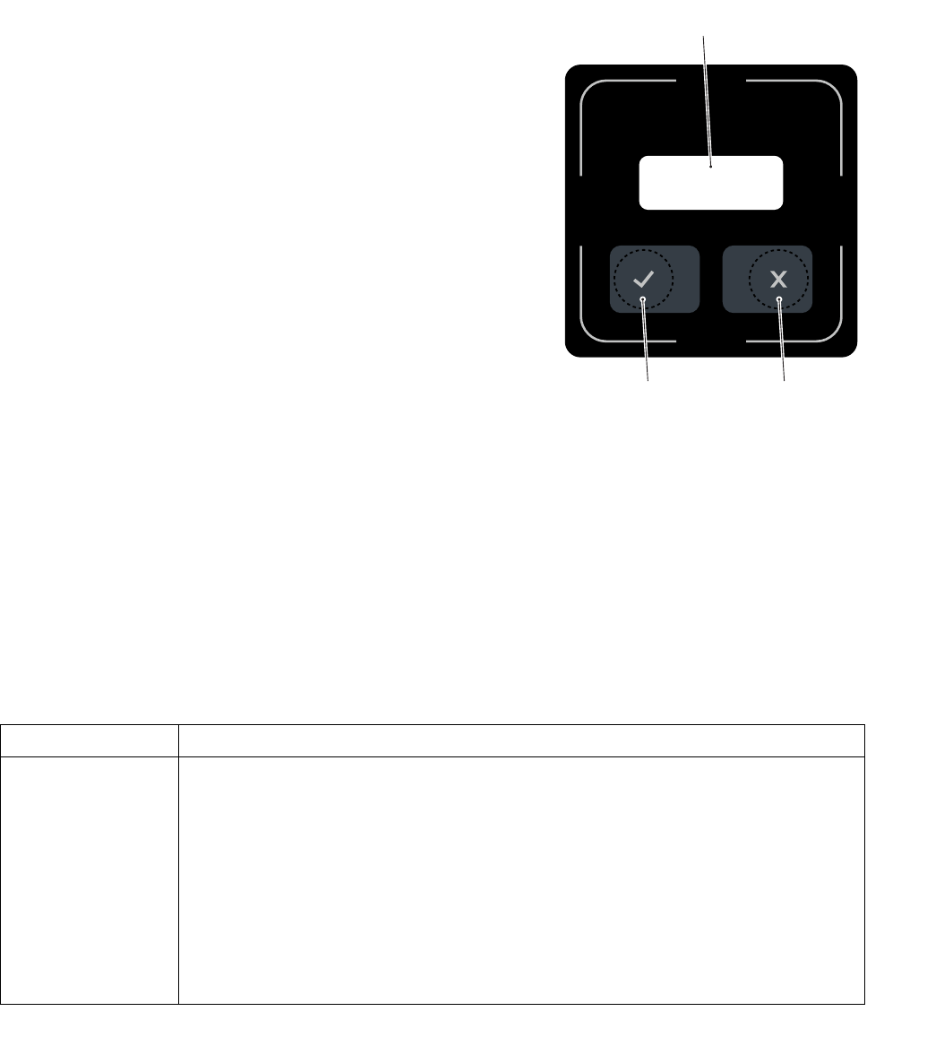
1 Description of indicators and controls
Item Display or operating
elements Function
1 Display
Display of the following information:
– Input commands
– Shock events
– Error messages
2Button
– Turn off the industrial truck.
– Only with activated query of the truck status,
see page 22:
– establish operational readiness when the
operator has determined damage.
3Button
– Make the industrial truck ready for operation.
– Only with activated query of the truck status,
see page 22:
– Confirmation that the operator has not
determined any damage to the truck.
I D E N T ?
1
2
3

02.17 US
14
2 Overview of the individual transponder types
ZFor the operation of the JUNGHEINRICH ISM online access module (information
system for stacker management), the following transponder types are used.
2.1 Operator transponder
The operator transponders fulfill the following functions:
– Assignment of the transponder to an operator.
– Access authorization for selected industrial trucks.
2.2 Master transponder
The master transponders fulfill the following functions:
– Assignment of the transponder to an operator (usually warehouse manager).
– Access authorization for all industrial trucks of the fleet.
– Cancellation of slow travel and truck stop in case of previous improper driving
(shock).
– Access authorization for industrial trucks in long-term storage.
2.3 Long-term storage transponders
The long-term storage transponders fulfill the following functions:
– Assignment of the transponder to an employee (usually warehouse manager).
– Longterm storage of an industrial truck. An operator’s transponder can no longer
be used to make the industrial truck ready for operation.
– Reset longterm storage of an industrial truck.

15
02.17 US
2.4 Technician transponder
The technician transponders fulfill the following functions:
– Assignment of the transponder to an employee/technician.
– Access authorization for all industrial trucks of the fleet.
– Access authorization for industrial trucks in long-term storage.
2.5 Delivery transponder
On delivery of the industrial truck, a delivery transponder is glued
to the access module. The delivery transponder fulfills the
following functions:
– Access authorization for the industrial truck during delivery
(before initial configuration).
– The transponder cannot be used after initial configuration of
the access module.
ZThe initial configuration of the access module is done in the
management portal. After the initial configuration, there is an authorization list with
at least one valid master transponder in the ISM online access module.
– Access authorization for the industrial truck if the industrial truck has been
disconnected in the management portal. In this case, no or an empty authorization
list is present in the ISM online access module.

02.17 US
16

17
02.17 US
D Operation
1 Establishing normal operation of the industrial truck/
preparing it for operation
ZAfter initial configuration, preparing an industrial truck for operation with the ISM
can only be done with a valid operator, master or technician transponder.
The following steps must be performed.
1.1 Release of the EMERGENCY OFF switch
Procedure
• Release the EMERGENCY OFF switch.
ZTo release the EMERGENCY OFF switch, refer
to the operating instructions.
Depending on the initial configuration and the
software version of the access module, the
indicator "IDENT?” or "CONNECT?” appears on
the display of the access module, see page 18.
ZDepending on the industrial truck, it may take a few seconds after the
EMERGENCY OFF switch is triggered until the "IDENT?” or "CONNECT?”
indicator lights up.
C O N N E C T ?
I D E N T ?
02.17 US
18
1.2 Indicators on the display of the ISM online access module after
release of the EMERGENCY OFF switch
After release of the EMERGENCY OFF switch, depending on the initial configuration
and the software version of the access module, different indicators appear on the
display of the access module.
The indicators and the meaning of the indicators on the display of the access module
are described in the following sections.
1.2.1 Display of the software versions, lock number and CAN-Bus model
Requirements
– EMERGENCY OFF switch released, see
page 17.
– On the display of the access module, the
indicator "IDENT?” or "CONNECT?” is displayed.
Procedure
• At the same time, press the buttons (2,3).
• On the display (1) of the access module, the
following pieces of information are displayed one
after another:
• Software version of the access module
(Beginning with a Z: ...).
• Software version of the data recorder
(Beginning with a D: ...).
• Software version of the radio module
(Beginning with a F: ...).
• Lock number of the access module.
• Set CAN-Bus model.
After the information mentioned has been displayed, (1)"IDENT?” or "CONNECT?”
appears on the display.
1.2.2 Indicators on the display of the ISM online access module (starting with
software version 03.0000 of the access module)
I D E N T ?
32
1
Indicator Meaning
IDENT?
Initial configuration of the ISM online access module has been
performed:
– ISM Online access module is known to the management portal.
– Authorization list with at least a valid operator, master or technician
transponder present in the ISM online access module.
– Operational readiness of the industrial truck can only be established
with a valid operator, master or technician transponder.
– An operator’s transponder cannot be used to make the industrial
truck ready for operation.

19
02.17 US
CONNECT?
Initial configuration of the ISM online access module was not performed
(e.g. on delivery of the industrial truck):
– No authorization list present in the ISM online access module (e.g. in
factory setting).
– Empty authorization list present in the ISM online access module.
– Only a delivery transponder can be used to make the industrial truck
ready for operation.
Indicator Meaning

02.17 US
20
1.3 Logging into the ISM online access module
1.3.1 Logging in with a valid operator, master and technician transponder
Requirements
– EMERGENCY OFF switch released, see
page 17.
– On the display of the access module, the
indicator "IDENT?” is displayed.
Procedure
• Place the valid transponder on the access
module.
• The access authorization is checked by the
access module.
If there is a valid operator transponder, a beep will
sound.
I D E N T ?
I D E N T ?

21
02.17 US
1.3.2 Logging in with the delivery transponder
ZOn delivery of the industrial truck, a delivery
transponder is glued to the access module. The
delivery transponder allows the industrial truck to
be made ready for operation before the initial
configuration.
Requirements
– EMERGENCY OFF switch released, see
page 17.
– Initial configuration of the access module has not
been performed (no or empty authorization list
present in the ISM online access module).
– On the display (1) of the access module, the
indicator "CONNECT?” is displayed (starting with
the software version "03.0000” of the access
module).
Procedure
• Place delivery transponder on the access
module.
• The access authorization is checked by the
access module.
If there is a valid delivery transponder, a beep will
sound. On the display of the access module, the
indicator "ok?” is displayed.
• Press the (3) key.
The industrial truck is ready for operation.
C O N N E C T ?
C O N N E C T ?
1
3

02.17 US
22
1.4 Checking the industrial truck status
ZSwitching the industrial truck on with one-level, two-level or without checking of the
industrial truck status is set in the management portal.
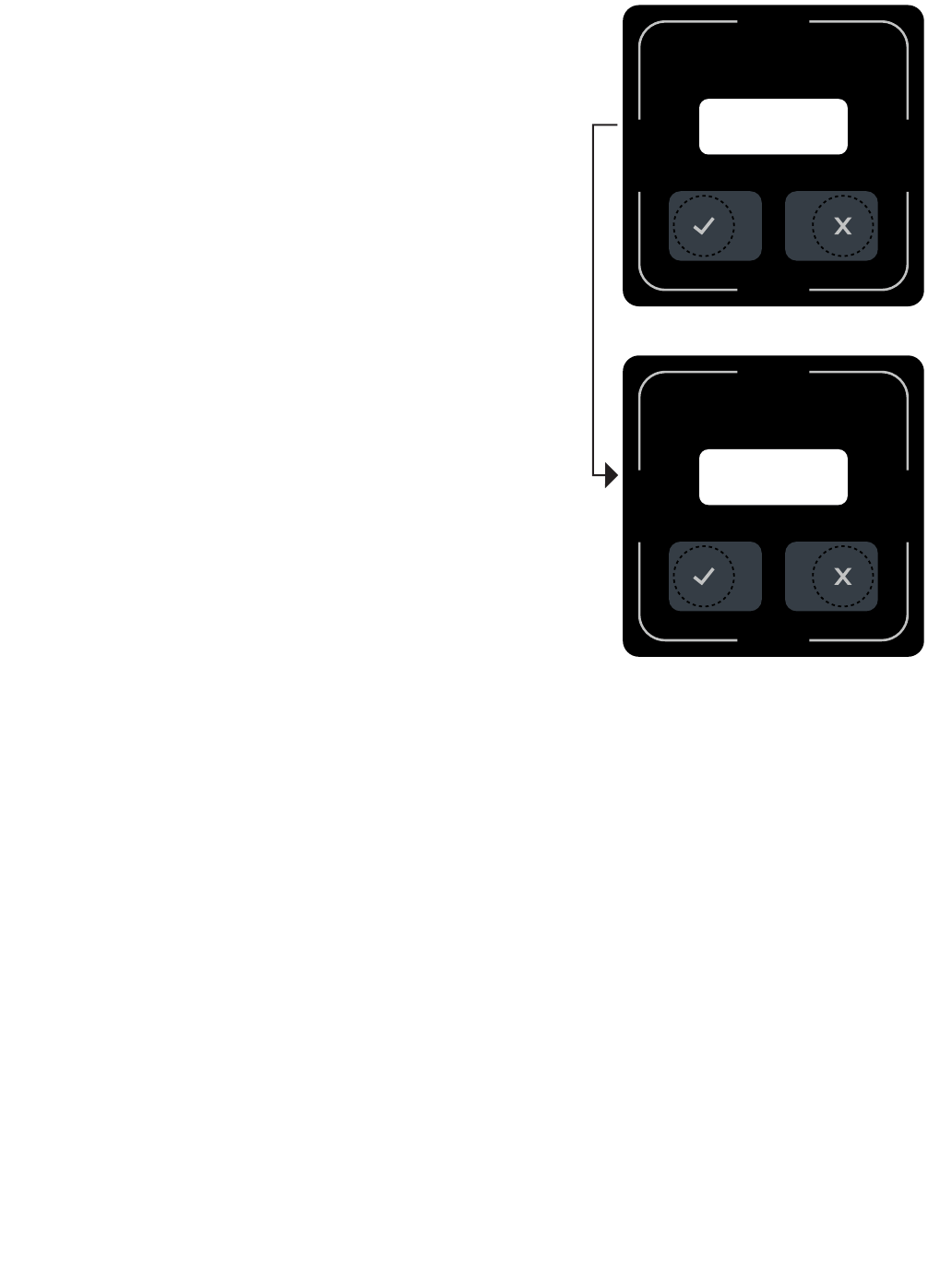
1.4.1 No checking of the industrial truck status
Requirements
– Checking of the industrial truck status is
deactivated.
Procedure
• Place the valid transponder on the access
module, see page 20.
• On the display of the access module, the
indicator "go!” is displayed.
The industrial truck is ready for operation.
g o !
23
02.17 US
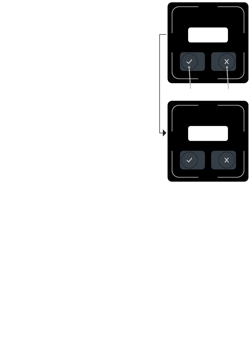
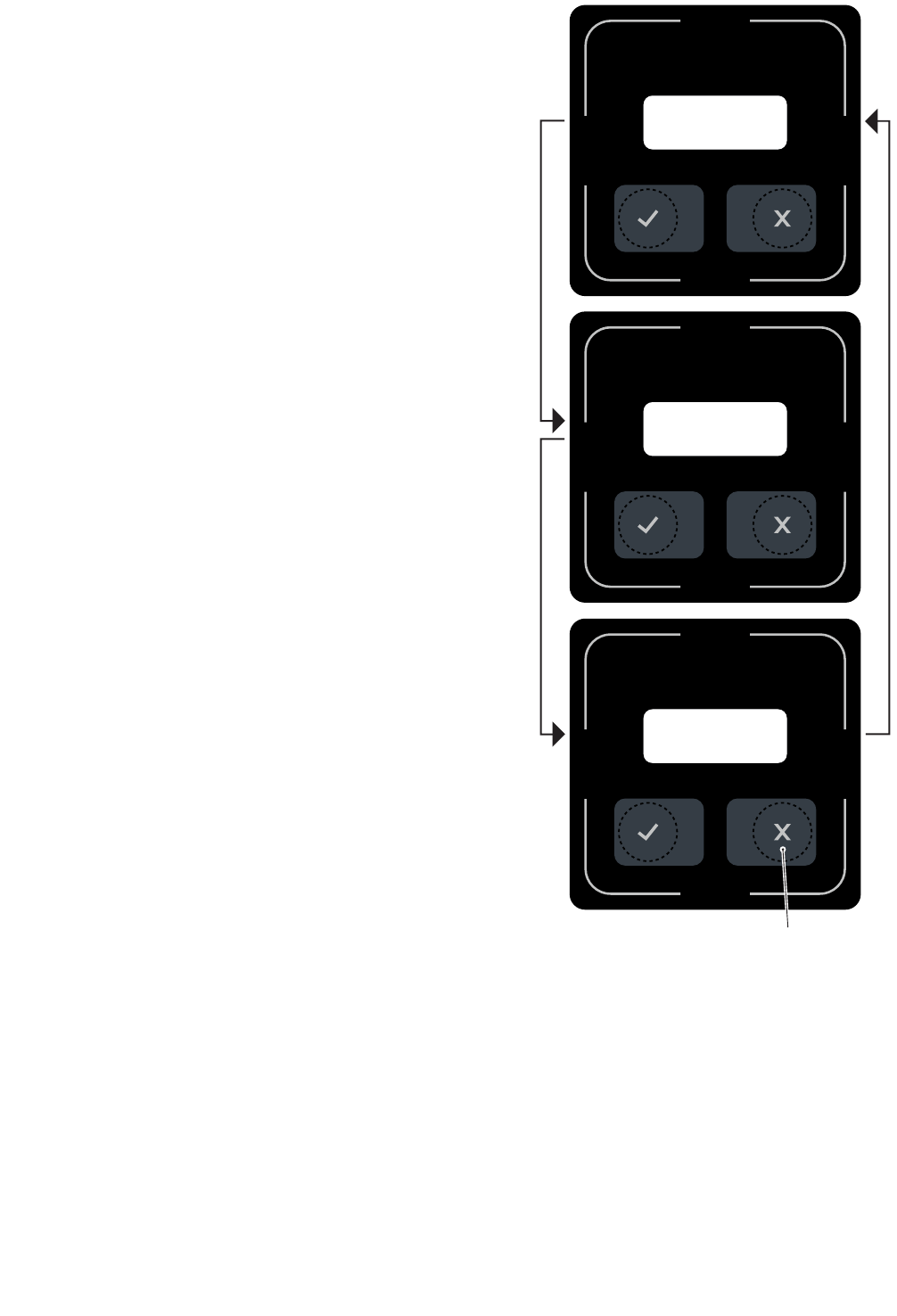
1.4.2 One-level checking of the industrial truck status
Requirements
– One-level checking of the industrial truck
status is activated.
Procedure
• Place the valid transponder on the access
module, see page 20.
On the display of the access module, the
indicator "ok?” is displayed. No steering and
hydraulic movements can be performed with
the industrial truck.
• Determine external status of the industrial
truck within 30 seconds after the illumination
of the "ok?” indicator:
ZIf the status of the industrial truck has not been
determined within 30 seconds, the indicator on
the display of the access module changes
from "ok?” to "IDENT?". The login process
must be started over.
•If no damage to the industrial truck has
been determined, press the (3) key.
The perfect exterior status of the industrial
truck has been confirmed.
•If damage to the industrial truck has been
determined, press the (2) key.
The damaged status of the industrial truck has been confirmed.
• On the display of the access module, the indicator "go!” is displayed.
The industrial truck is ready for operation.
ggo !
o k ?
32
02.17 US
24
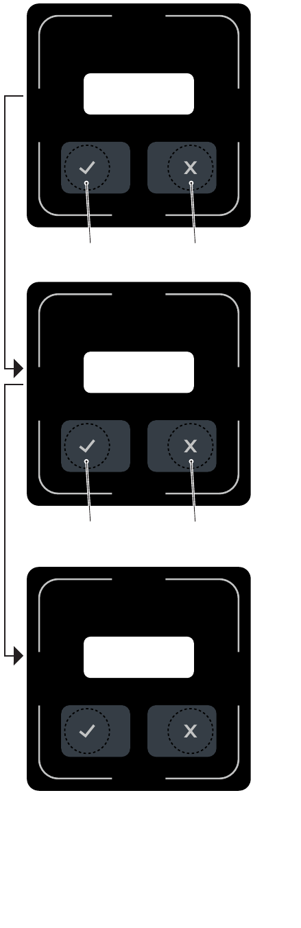
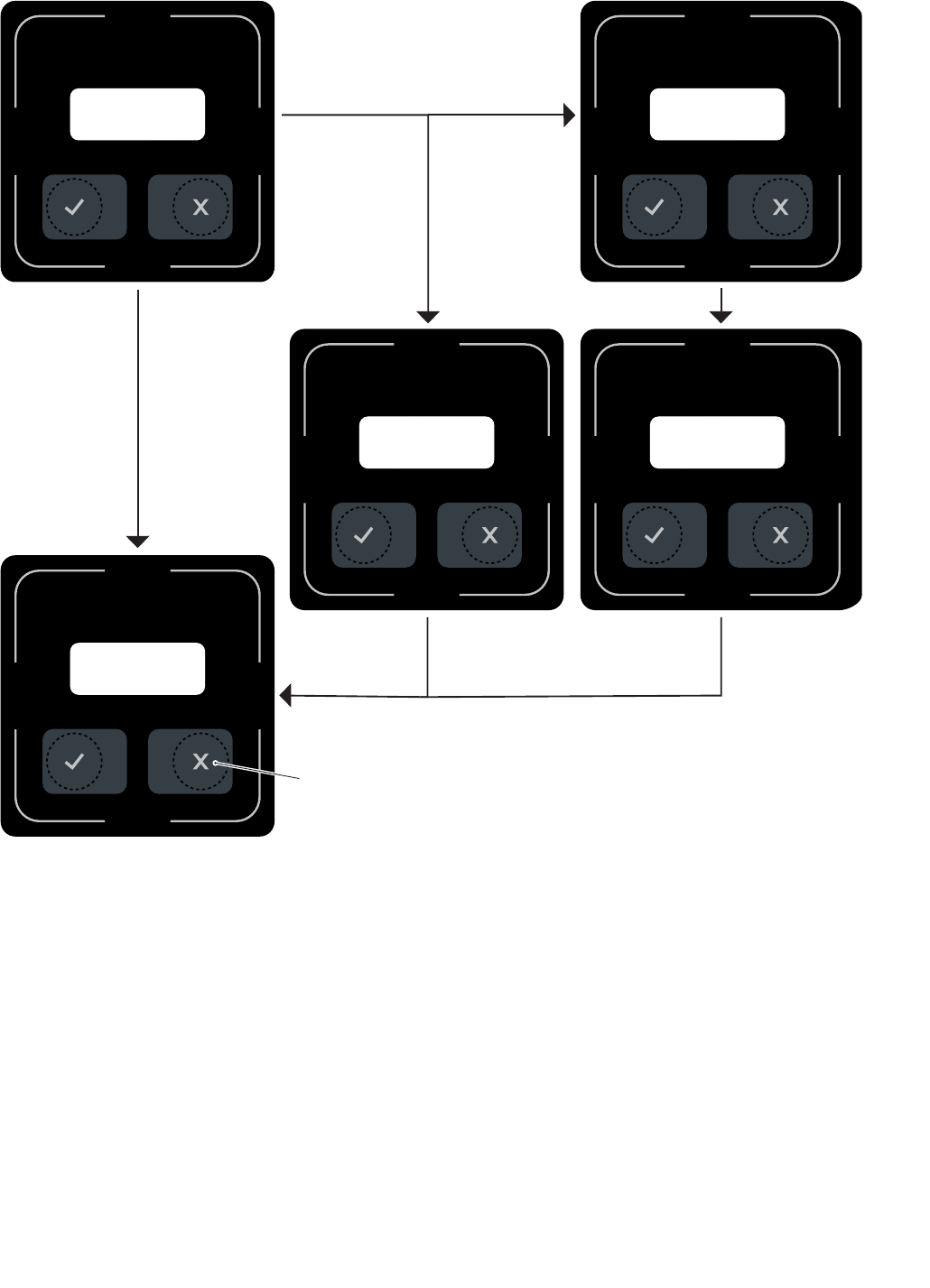
1.4.3 Two-level checking of the industrial truck status
ZSwitching on the industrial truck with the two-level checking of the industrial truck
status is only possible starting with the software version "03.0000” of the access
module.
Requirements
– Two-level checking of the industrial truck
status is activated.
Procedure
• Place the valid transponder on the access
module, see page 20.
On the display of the access module, the
indicator "ok1?” is displayed. No steering and
hydraulic movements can be performed with
the industrial truck.
• Determine external status of the industrial
truck within 30 seconds after the illumination
of the "ok1?” indicator:
ZIf the status of the industrial truck has not been
determined within 30 seconds, the indicator on
the display of the access module changes
from "ok1?” to "IDENT?.” The login process
must be started over.
•If no damage to the industrial truck has
been determined, press the (3) key.
The perfect exterior status of the industrial
truck has been confirmed.
•If damage to the industrial truck has been
determined, press the (2) key.
The damaged status of the industrial truck
has been confirmed.
• On the display of the access module, the
indicator "ok2?” is displayed.
Industrial trucks that support the “slow travel”
function under ISM can now be driven at this
reduced speed. The same applies to the
hydraulic speeds.
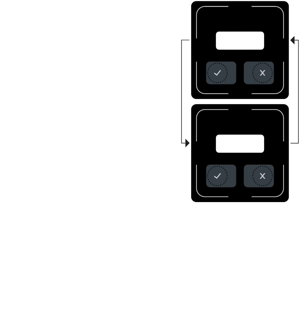
• Perform a test run with the industrial truck.
While so doing, check the travel and hydraulic
movements:
•If no defects have been determined during
the test run, press the (3) key.
The perfect status of the industrial truck has
been confirmed.
•If defects have been determined during the test run, press the (2) key.
The damaged status of the industrial truck has been confirmed.
• On the display of the access module, the indicator "go!” is displayed.
g o !
o k 2 ?
o k 1 ?
32
32

25
02.17 US
The industrial truck is ready for operation. The travel and hydraulic movements can
be performed at the maximum released speeds.
1.5 Behavior in case of invalid operator transponder
Requirements
– EMERGENCY OFF switch released, see
page 17.
Procedure
• If the indicator "XIDENT??” appears for 30
seconds on the display of the access module, an
invalid operator transponder was held on the
access module.
ZThe last two digits of the indicator "XIDENT??”
provide the reason for the release of the industrial
truck that was not granted, see page 35.
The industrial truck cannot be made ready for operation with this transponder.
XXI D E N T ? ?

02.17 US
26
1.6 Switching off the industrial truck
1.6.1 Switching off the industrial truck manually
Requirements
– The industrial truck has been made ready for
operation.
Procedure
• Press the (2) key.
The travel operation has ended. The industrial
truck is switched off (exception: warehouse and
system vehicles). On the display of the online
access module, the indicator " ISM IDENT?”
appears. A new travel operation can be started.
• Particularity for warehouse and system vehicles:
• To switch off the industrial truck, press the (2)
key again.
NOTICE
If the industrial truck could not be switched off by pressing the (2) button again, this
has been prevented by the industrial truck.
For conscious switching off of the industrial truck by the operator, the (2) button
must be pressed for at least 2 seconds.
The industrial truck is switched off.
IID E N T ?
2

27
02.17 US
1.6.2 Switching off the industrial truck automatically
Requirements
– The industrial truck has been made ready for operation.
Procedure
• After an adjustable period of time (timeout) has elapsed in which no vehicle
activities have been performed with the industrial truck, the industrial truck switches
itself off automatically.
ZDepending on the vehicle type, the following vehicle functions can be defined as
vehicle activities:
- Travel operations of the industrial truck
- Lifting and/or lowering operations of the industrial truck
etc.
The industrial truck is switched off. On the display of the online access module, the
indicator " ISM IDENT?” appears. A new travel operation can be started.

02.17 US
28
1.7 Particularity for warehouse and system vehicles
For warehouse and system vehicles, after elapsing
of a stand-by timer, the indicator "standby” on the
display of the access module.
The industrial truck can no longer be used in this
status. By placing the last operator transponder
used on the access module, the industrial truck can
be switched on again. The checking of the industrial
truck status is omitted.
ZAll other valid operator transponders can only
switch the industrial truck on after it has been
switched off again, see page 26.
sst a n d b y
29
02.17 US
2 Behavior in case of shock events
Improper operator actions are stored in the data recorder and can be displayed via a
message on the access module if necessary. The industrial truck can react in
different ways to a shock event. The various reactions of the industrial truck are
described below.
2.1 Saving the shock
In this configuration, all shock events are saved. The response of the industrial truck
is not taken into consideration.
2.2 Saving and displaying shocks
In this configuration the operator is informed
that a serious shock has occurred.
On the display of the access module, for
30 seconds a shock warning "shock!” is
displayed. Then the message "go!” appears
on the display.
The shock event is saved in the data
recorder.
The response of the industrial truck is not
taken into consideration.
ggo !
s h o c k !
30 sec.

02.17 US
30
2.3 Saving and displaying shocks with industrial truck in slow travel
In this configuration the operator is informed
that a serious shock has occurred.
The shock event is saved in the data
recorder.
After such a shock event, the shock warning
"shock!” and the command "M-IDENT” are
displayed in alternation.
Industrial trucks that support the “slow travel”
function under ISM online can now only be
driven at this reduced speed.
The industrial truck can only be operated in
slow travel after switching the operator or
technician transponder off and then on
again. The display of the access module
once again displays the shock warning
"shock!” and the command "M-IDENT” in
alternation.
ZThe shock event and the slow travel of the
industrial truck can only be canceled with a
master transponder.
MM- I D E N T
s h o c k !
31
02.17 US
Reset shock event and cancel slow travel
of the industrial truck:
Procedure
• Press the (2) key.
The industrial truck is switched off. On the
display of the access module, the indicator
"shock! – M-IDENT – IDENT?” appear in
alternation.
• Place master transponder on the access
module.
On the display of the access module, the
message "IDENT?” appears and a beep
sounds. Slow travel of the industrial truck
has been canceled.
• The industrial truck can be made ready for
operation with a valid operator
transponder, see page 20.
MM- I D E N T
I D E N T ?
s h o c k !
2

02.17 US
32
2.4 Saving and displaying shocks with the industrial truck stopped
In this configuration the operator is informed
that a serious shock has occurred.
After such a shock event, the shock warning
"shock!” and the command "M-IDENT” are
displayed in alternation.
The industrial truck is switched off after
recognizing the shock event.
The industrial truck cannot be made ready
for operation with the operator or technician
transponder.
ZThe locking of the industrial truck can only
be canceled by a master transponder.
MM- I D E N T
s h o c k !

33
02.17 US
Resetting a shock event / Canceling lock of the
industrial truck:
Procedure
• Place master transponder on the access module.
On the display of the access module, the
message "IDENT?” appears and a beep sounds.
• The industrial truck can be made ready for
operation again with a valid operator transponder
or technician transponder, see page 20.
IID E N T ?

02.17 US
34
3 Troubleshooting
3.1 Faults
Malfunction Possible cause Actions
Industrial truck cannot be
switched on
– No power supply available
on the access module
– Connect the battery
connector to the industrial
truck.
– Release the EMERGENCY
OFF switch.
– Properties of the
transponder unclear
– Heed the indicators on the
ISM online access module:
- XIDENT01
- XIDENT02
- XIDENT03
- XIDENT09
– Check properties of the
transponder, see page 35.
Industrial truck cannot be
switched on with the
master transponder
– Access module is defective – Replace ISM online access
module.
No shocks are recorded
– Too-high switching
threshold of the shock
sensor
– Reduce switching threshold
of the shock sensor in the
management portal by the
fleet manager.
Too many shocks are
recorded
– Too-low switching threshold
of the shock sensor
– Increase switching
threshold of the shock
sensor in the management
portal by the fleet manager.
No data transmission of
the industrial truck to the
system
– Industrial truck is outside of
the range of the gateway
– Drive industrial truck into
transmission range of the
gateway of approx. 98.5 ft
(30 m).
– Make sure that the visual
connection of antenna of
the radio module to the
antenna gateway is
ensured.
Industrial truck does not
transmit any data
– Radio module is defective
– Data recorder does not
transmit any signals to the
radio module
– Check radio transmission.
– Replace radio module.
– Replace data recorder.

35
02.17 US
3.2 Indicator "XIDENT??" on the display of the access module
Indicator Possible cause Actions
XIDENT01
– Operator transponder was taken
away from the access module too
fast
– Operator transponder could not
be read
– Keep operator transponder on the
access module longer
XIDENT02
– Operator transponder locked with
stored industrial truck
– Release industrial truck for
operation again with long-term
storage transponder
– Place operator transponder on
the access module again
XIDENT03
– Validity of the operator
transponder expired
– Increased validity duration of the
operator transponder in the
management portal
XIDENT09
– Operator transponder can be
read
– No release for this operator
transponder entered in the
access module
Note:
In addition to the indicator
"XIDENT09” you will hear five short
beeps.
– Entering transponder for the
industrial truck in the
management portal

02.17 US
36
3.3 Error messages "Er. 101x - Er. 103x" on the display of the access
module
ZTroubleshooting may only be performed by the manufacturer. The manufacturer
has customer service technicians who are specially trained for these tasks.
The following information is crucial and helpful for the dealer to be able to respond
to the fault quickly and accurately:
- Serial number of the industrial truck
- Error number from the display of the access module (if present)
- Error description
- Current location of the industrial truck.
Malfunction "Er. 101x - Er. 103x”
The access module has a self-diagnostic option that can be used to restrict error
sources. The last digit of the error message limits the cause of the error source and
is relevant for the manufacturer's customer service.
Indicator Possible cause Possible error source
Er. 101x
– Error or defect on the
inputs or outputs of the
optional sensors 1, 2 or 3
– Replace defective optional sensors 1, 2
or 3
Er. 102x
– Internal error (software
error, internal hardware
defective)
– Check wiring of the ISM online
components
– Defective ISM replace online components
Er. 103x
– Incorrect
parameterization of the
ISM online components
– Inconsistent parameterization
Example:
– Sensor threshold value 1 is greater
than sensor threshold value 2
– Stand-by timeout is greater than
timeout

37
02.17 US
4 Longterm storage of industrial trucks
The industrial trucks can be stored long-term and put back into operation with the help
of a valid longterm storage transponder.
4.1 Release of the EMERGENCY OFF switch
Procedure
• Release the EMERGENCY OFF switch.
ZTo release the EMERGENCY OFF switch, refer
to the operating instructions.
Depending on the initial configuration and the
software version of the access module, the
indicator "IDENT?” or "CONNECT?” appears on
the display of the access module, see page 18.
ZDepending on the industrial truck, it may take a few seconds after the
EMERGENCY OFF switch is triggered until the "IDENT?” or "CONNECT?”
indicator lights up.
C O N N E C T ?
I D E N T ?

02.17 US
38
4.2 Extended shutdown of the industrial truck
Procedure
• Place the valid longterm storage transponder on
the access module.
The industrial truck was stored long-term with the
longterm storage transponder. On the display of the
online access module, the indicator "ISM "locked”
is displayed.
llo c k e d
39
02.17 US
4.3 Restarting the industrial truck after shutdown
4.3.1 Canceling longterm storage of the industrial truck
Requirements
– Industrial truck was stored long-term with
longterm storage transponder, see page 38.
Procedure
• Place the valid longterm storage transponder
on the access module.
The industrial truck is now released for
operation again. On the display of the online
access module, the indicator "ISM "IDENT?”
is displayed.
• The industrial truck can be made ready for
operation with a valid operator transponder,
see page 20.
IID E N T ?
l o c k e d
02.17 US
40
4.3.2 Switching on stored industrial truck with master transponder or technician
transponder
ZAn industrial truck stored long-term can be released for a travel order briefly with
the master or technician transponder.
Example:
The industrial truck must be driven to a place where safe repair of the industrial
truck can be guaranteed.
Requirements
– Industrial truck was stored long-term with longterm storage transponder, see
page 38.
Procedure
• Place the valid master or technician transponder on the access module.
On the display of the ISM online access module, depending on the check of the
vehicle state, the indicator "ok?,” "ok1?” or "go!” appears.
• Switch industrial truck on depending on the check of the vehicle state:
ook 2 ?o k ?
o k 1 ?
g o !
l o c k e d
2

41
02.17 US
• Switch on industrial truck with deactivated check of the vehicle status, see
page 22.
• Switch on industrial truck with activated one-level check of the vehicle status,
see page 23.
• Switch on industrial truck with activated two-level check of the vehicle status, see
page 24.
• On the display of the access module, the indicator "go!” is displayed.
The industrial truck is ready for operation.
• Press the (2) key to switch the industrial truck off and take it out of operation.
On the display of the online access module, the indicator "ISM "locked”
is displayed.
ZAfter the industrial truck has been reset into the proper status, the longterm storage
of the industrial truck must be canceled, see page 39.

02.17 US
42

43
02.17 US
E Gateway (GW 110) of the ISM online
1 Technical data
The gateway (GW 110) with power pack corresponds to part 15 of theFCC
regulations. Operation is subject to the following conditions:
– The gateway (GW 110) with power pack causes no damaging malfunctions.
– The function of the gateway (GW 110) with power pack is not influenced adversely
by fault signals received.

02.17 US
44
1.1 Technical specifications of the gateway (GW 110)
NOTICE
The gateway corresponds to the essential protection requirements that are specified
in the directive of the advisory council for approximation of the laws of member states
about electromagnetic compatibility 2014/30/EU, as well as in the low-voltage
directive 2014/35/EU.
Processor Intel® Atom TM Dual Core Processor 2 x 1.6 GHz (N2600)
RAM 1 GB DDR3
Mass storage 2 GB Flash
Operating system Linux
Voltage supply 15 V DC (12 V to 24 V) via 2.5 mm stereo jack
Power consumption approx. 13 W
Interfaces
– Ethernet 1000-BaseT/100-BaseT/10-BaseT Autoswitch
(RJ45 connection) “LAN1”
– Ethernet 100-BaseT/10-BaseT Autoswitch (RJ45
connection) “LAN2”
– 2 x USB 2.0
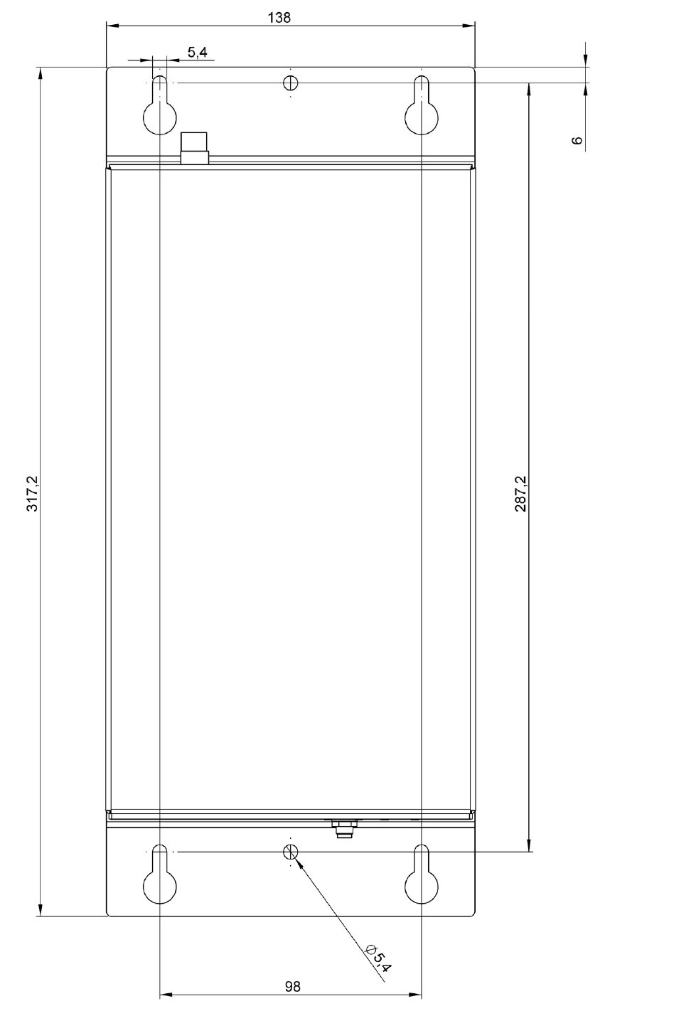
Dimensions
– Width: approx. 138 mm
– Height: approx. 317 mm
– Depth: approx. 138 mm
Attachment – 4 screws (5 mm) for attachment of the gateway
– 2 screws (5 mm) for additional securing of the gateway
Weight 2.4 kg (without power pack)
Protection type IP52
Electromagnetic
Compatibility (EMC) EN55022 Class B
Ambient temperature 0 °C to 45 °C (in operation)
Relative humidity 5 % to 95 % (in operation), no condensation
Communication
– Integrated GSM/GPRS module (quadband)
850 MHz / 900 MHz / 1800 MHz / 1900 MHz,
Radio output power max. 2 W,
Connection via FME male
– Integrated narrow band radio module 433 MHz,
Connection via SMA female
– 6 LEDs for status indication

45
02.17 US
1.2 Technical specifications of the power pack
Voltage supply 100 V AC to 240 V AC
Supply frequency 50 Hz to 60 Hz
Maximum input current 1.0 A
Maximum input voltage 43.4 W
Output voltage 14.25 V DC to 15.75 V DC
Maximum output current 2.4 A
Input fuse Internal primary amperage fuse
Input limitation
Output reaction time 50 ms
Output fuse
– Short-circuit fuse
– Overvoltage protection
– Overcurrent protection
Safety certificates
– TÜV (EN 60950-1)
– CE (Declared_CE Mark)
– T-Mark (BS EN 60950-1)
– RCM (AS/NZS60950.1)
– UL (UL 60950-1)
– cUL (CSA C22.2 NO.950)
Electrical construction Switching line transformer
Electromagnetic Compatibility
(EMC)
– FCC rules part 15: Class B
– EN55022: Class B
Electromagnetic immunity to
interference
– EN 55024
– EN 61000-4-2,-3,-4,-5
Dielectric strength Primary - secondary
3000 VAC, 10 mA, 1 Minute
Leakage current 0.25 mA
Insulation resistance Input - output
10 MΩ at 500V DC (min.)
Ambient temperature 0 °C to 40 °C (in operation)
Relative humidity – 5% to 90% (in operation)
– No condensation
Cooling Convection cooling via surface
Housing (layout and material) – EN 60950-1
– UL 94V-1 (housing)
Dimensions
– Width: approx. 1.8 in (48.0 mm)
– Height: approx. 4.4 in (110.8 mm)
– Depth: approx. 1.3 in (33.6 mm)
02.17 US
46
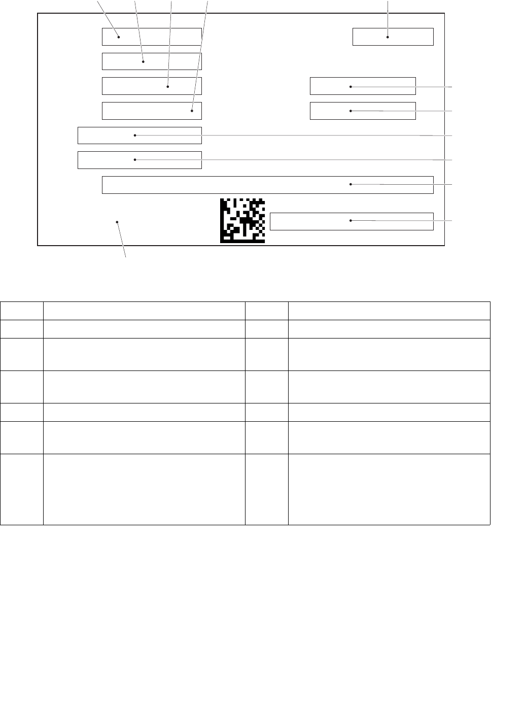
2Nameplate
Item Designation Item Designation
4 Type designation 10 Revision number
5 Serial number 11 Address of the network connection
LAN1
6 Type number 12 Address of the network connection
LAN2
7 Item number 13 Manufacturer
8Calendar week / year of
manufacture 14 Manufacturer's logo
9 Supplier number 15
FCC and IC identifier.
The gateway (GW 110) with power
pack corresponds to part 15 of
theFCC regulations, see page 43.
Typ
Type
Typennummer
Type number
Serien-Nr.
Serial no.
Sachnummer
Part number
KW/Baujahr
Calendar Week /Year of manufacture
Lieferanten-Nr.
Supplier no.
Revisionnummer
Revision number
Contains FCC ID: 02F-xxxxxxxxxxx
and IC: xxxxxxxxxxxxxxxxxxx
Hersteller
Manufacturer
LAN1
LAN2
46
12
57
9
10
11
8
14
13
15

47
02.17 US
3 Description of indicators and controls
Item Designation
16 LED "MAIN”
17 LED "RSP”
18 LED "From RSP”
19 LED "To RSP”
20 LED "Radio”
21 LED "GSM” (LED is out of service)
22 Connection of the 915 MHz antenna “connection of gateway to industrial truck”
23 Network connectionLAN1
24 Network connectionLAN2
25 USB connection 1
26 USB connection 2
27 Voltage supply
MAIN
RSP
From RSP
To RSP
Radio
GSM
LAN 1 LAN 2
16 17 18 19 20 21 22 23 24 25 26 27

02.17 US
48
4 Description of the LEDs
LED
designation Indicator Meaning
MAIN (16)
OFF
– Gateway is not connected to the power
network.
During the operating phase:
– Software "Maintask” not started.
Flashing GREEN:
- 1 seconds on
- 1 seconds off
During the operating phase:
– Normal operating condition after boot-up
of the gateway.
– Software "Maintask” is ready for
operation.
GREEN
During the boot-up phase (< 30 seconds
after switching on the gateway):
– LED lights up during boot-up of the
gateway.
During the operating phase:
– Software "Maintask” is not ready for
operation.
RED
During the operating phase:
– Software "Maintask” has determined an
internal error.

49
02.17 US
RSP (17)
OFF
During the boot-up phase (< 30 seconds
after switching on the gateway):
– LED does not light up during boot-up of
the gateway.
During the operating phase:
– Connection software to transfer server
not started.
Flashing GREEN:
- 1 seconds on
- 1 seconds off
During the operating phase:
– Normal operating condition after boot-up
of the gateway.
– Connection software to the transfer
server is ready for operation.
Flashing RED:
- 1 seconds on
- 1 seconds off
During the operating phase:
– Error in the communication to the transfer
server.
GREEN
During the operating phase:
– Connection software to the transfer
server is not ready for operation.
ORANGE
During the operating phase:
– Gateway is receiving data from the
transfer server.
RED
During the operating phase:
– Gateway is sending data to the transfer
server.
From RSP (18)
OFF
During the boot-up phase (< 30 seconds
after switching on the gateway):
– LED does not light up during boot-up of
the gateway.
During the operating phase:
– No data is present in the gateway that
must be sent to the industrial truck.
– No data is present in the gateway that
must be processed by the gateway.
ORANGE
During the operating phase:
– Data is present in the gateway that must
be sent to the industrial truck.
– Data is present in the gateway that must
be processed by the gateway.
LED
designation Indicator Meaning

02.17 US
50
To RSP (19)
OFF
During the boot-up phase (< 30 seconds
after switching on the gateway):
– LED does not light up during boot-up of
the gateway.
During the operating phase:
– No data is present in the gateway that
must be sent to the transfer server.
ORANGE
During the operating phase:
– Data is present in the gateway that must
be sent to the transfer server.
Radio (20)
OFF
During the boot-up phase (< 30 seconds
after switching on the gateway):
– LED does not light up during boot-up of
the gateway.
During the operating phase:
– Radio connection to the industrial truck
not ready for operation.
GREEN – Radio connection to the industrial truck
ready for operation.
ORANGE – Gateway is receiving data from the
industrial truck.
RED – Gateway is sending data to the industrial
truck.
GSM (21) OFF
No meaning.
– The LED is out of service and is not
controlled by the gateway.
LED
designation Indicator Meaning

51
02.17 US
5 Troubleshooting
This chapter enables the user to localize and eliminate basic faults by himself. When
trying to locate a fault, follow the order of actions shown in the table for rectifying
faults.
ZIf, after carrying out remedial actions, the gateway cannot be restored to operation
or if a fault or a defect is indicated by the illumination of other LEDs, contact the
manufacturer’s customer service. Additional troubleshooting may only be
performed by the manufacturer. The manufacturer has customer service
technicians who are specially trained for these tasks.
LED
designation Indicator Remedy
MAIN (16)
OFF
– Check voltage supply of the gateway.
– Disconnect voltage supply from the
gateway for at least 30 seconds (e. g.
unplug plug, switch outlet voltage-free,
etc.).
– Restore voltage supply to the gateway.
RSP (17)
From RSP (18)
To RSP (19)
Radio (20)
GSM (21)
MAIN (16)
GREEN
During the boot-up phase (> 30 seconds
after switching on the gateway):
– Disconnect voltage supply from the
gateway for at least 30 seconds (e. g.
unplug plug, switch outlet voltage-free,
etc.).
– Restore voltage supply to the gateway.
RED
– Disconnect voltage supply from the
gateway for at least 30 seconds (e. g.
unplug plug, switch outlet voltage-free,
etc.).
– Restore voltage supply to the gateway.
RSP (17) GREEN
During the boot-up phase (> 30 seconds
after switching on the gateway):
– Disconnect voltage supply from the
gateway for at least 30 seconds (e. g.
unplug plug, switch outlet voltage-free,
etc.).
– Restore voltage supply to the gateway.
02.17 US
52
6 Hole pattern of the gateway (GW 110)

53
02.17 US
F Maintenance of the ISM online
components and the gateway (GW 110)
1 Operating safety
The checks and servicing operations contained in this chapter must be performed in
accordance with the maintenance intervals as indicated in the servicing checklists.
Personnel for maintenance and servicing
ZThe manufacturer’s sales department has a customer service team specially
trained for these tasks. Signing a maintenance agreement with the manufacturer’s
responsible sales center will ensure problem-free operation.
Maintenance and servicing of the following components may only be performed by
the manufacturer's customer service team or by customer service authorized by the
manufacturer.
– ISM online components
– Gateway (GW 110)
Maintenance and servicing must be performed in accordance with the procedures
described in this chapter.
Customer service
Customer service is specially trained on the ISM online components and gateway
(GW 110) and is in a position to perform maintenance and service work
independently. Customer service is familiar with the standards, regulations and safety
requirements that must be followed for these tasks.
In unusual circumstances not described in these Operating Instructions, please
contact the industrial truck manufacturer.

02.17 US
54
2 Safety regulations for maintenance
Applicable safety regulations for the maintenance and replacement of the ISM
online components and gateway (GW 110)
Before maintenance or replacement of the ISM online components and gateway (GW
110), the following prerequisites for the work area must be taken into consideration:
– There is no danger of fire.
– Tools and equipment for firefighting are present in the work area.
– There is sufficient ventilation of the work area.
– The work area is clean and dry.
Attention must be paid that the spare parts are identical to the original components.
The spare parts must corresponds to the original equipment with respect to quality
and performance. All parts must be fitted in accordance with the manufacturer's
instructions.
NOTICE
Only original spare parts are subject to the manufacturer's quality control. To ensure
safe and reliable operation of the industrial truck, use only the manufacturer's spare
parts.

55
02.17 US
3 Working on the electrical system
3.1 Preparing the industrial truck for maintenance and servicing
WARNING!
Risk of accidents due to electrical current
Work on the ISM online components is only permitted when the electrical power is
turned off. The capacitors built into the industrial truck must be completely
discharged. The capacitors are completely discharged after approx. 10 min.
Only suitably-trained electricians may work on the ISM online components.
Take all necessary actions before beginning work to exclude the possibility of an
electrical accident.
Park and secure the industrial truck (see appropriate section in the operating
instructions for the industrial truck in question).
Unplug the industrial truck’s battery plug.
Remove rings, metal armbands, etc.
To prevent accidents during maintenance and service work on the ISM online
components, the following necessary safety measures must be adhered to:
Procedure
• Lower the lifting accessory of the industrial truck completely.
• Park the industrial truck safely (see operating instructions for the industrial truck).
• Switch the industrial truck off; see operating instructions for the industrial truck.
• Press the EMERGENCY OFF switch.
• Disconnect the battery to prevent the industrial truck from being switched on
accidentally.

02.17 US
56
3.2 Preparing the gateway (GW 110) for maintenance and service work
WARNING!
Risk of accidents due to electrical current
Work on the gateway (GW 110) is only permitted when the electrical power is turned
off. The capacitors built into the gateway must be completely discharged. The
capacitors are completely discharged after approx. 10 min.
Disconnect network supply before performing work on the gateway.
Remove rings, metal armbands, etc.
To prevent accidents during maintenance and service work on the gateway (GW
110), the following necessary safety measures must be adhered to:
Procedure
• Disconnect network supply to the gateway (GW 110).

57
02.17 US
4 Cleaning
NOTICE
Risk of damage to the ISM online components and the gateway (GW 110)
Cleaning the ISM online components and the gateway (GW 110) with water can
cause damage to the electrical system.
Do not clean ISM online components and the gateway with water.
Clean ISM online components with weak suction or compressed air (use a
compressor with a water trap) and a non-conductive, anti-static brush.
5 Permanent decommissioning and disposal
ZThe proper permanent decommissioning or disposal of the ISM online components
and gateway (GW 110) must be carried out in accordance with the applicable legal
provisions of the country in which the devices are used. In particular, regulations
related to the disposal of electronics must be observed.
Disassembly of the ISM online components and gateway (GW 110) may only be
performed by trained persons and the manufacturer's recommended procedures
must be followed.
CAUTION!
Old parts endanger the environment
Old parts must be disposed of correctly in accordance with applicable environment
protection regulations.
Comply with safety regulations when handling these old parts.

02.17 US
58

59
02.17 US
G Maintenance and inspection
WARNING!
Risk of accident due to neglected maintenance
Ignoring routine maintenance can cause the industrial truck to break down and the
ISM online components to fail and presents a potential risk to personnel and
equipment. The same applies for the gateway (GW 110).
A thorough and professional maintenance service is one of the most important
requirements for the safe use of the industrial truck with ISM online components.
The same applies for the gateway (GW 110).
Operating conditions for the industrial truck can have a significant impact on the wear
of ISM online components. The maintenance intervals specified below assume
single-shift operation and normal usage conditions. Under more strenuous conditions
such as a very dusty environment, large fluctuations in temperature, or multi-shift
operation, shorten intervals accordingly.
NOTICE
To agree on maintenance intervals, the manufacturer recommends a usage analysis
on-site in order to prevent damage due to wear.
The maintenance checklist below sets out the jobs to be done and the intervals at
which they are required. Maintenance intervals are defined as:
ZW maintenance intervals must be performed by the operator.
W = Every 50 operating hours, or at least once a week
A = Every 500 operating hours
B = Every 1000 operating hours, or at least once a year
C = Every 2000 operating hours, or at least once a year
t= Standard maintenance interval
k=Cold storage maintenance interval (in addition to standard maintenance
interval)

02.17 US
60
1 Maintenance check list
1.1 Maintenance checklist - electrical system
Information system stacker management (ISM online components)
Gateway (GW 110)
Information system stacker management (ISM online components) W A BC
1Test the access module; check for damage and make sure it is
properly attached. t
2Check the data recorder for damage and make sure it is securely
attached. t
3Check the radio module for damage and make sure it is securely
attached. t
4 Check cabling for damage and to make sure it is properly attached. t
Gateway (GW 110) W A B C
1Test the gateway; check for damage and make sure it is properly
attached. t
2Test the power pack; check for damage and make sure it is properly
attached. t
3Check the antenna for damage and make sure it is securely
attached. t
4 Check cabling for damage and to make sure it is properly attached. t