Juniper Systems 19799AR BC04 User Manual part 2
Juniper Systems, Inc. BC04 part 2
Contents
- 1. User Manual part 1
- 2. User Manual part 2
- 3. User Manual
- 4. Users Manual
User Manual part 2

User’s Guide
User’s Guide
Reference Guide

User’s Guide
Supported
Bluetooth®
proles
Serial Port Profile
Dial-Up Networking (DUN) Profile
Human Interface Device (HID) Profile
Object Push Profile (OPP)
9

82
This chapter describes the Bluetooth® profiles
recognized by the Microsoft drivers installed on your
Field PC. Drivers determine which devices your Field
PC can communicate with. If you are using an external
Bluetooth CF or SDIO card and you installed a new
driver specific to this card (recommended), consult the
documentation that came with the driver for instructions
about its profiles.
Note: Bluetooth cards are not recognized by modules
with integrated Bluetooth. For general instructions about
using an integrated Bluetooth module, see Chapter 8.
This chapter is organized by Bluetooth profile, each of
which is briefly described below. Instructions for using
each profile to create Bluetooth partnerships follow.
Serial Port Profile (SPP). Similar to a serial cable, this
profile acts as a liaison between two devices, such as
the Field PC and a GPS receiver, using virtual ports.
(These ports are described in the previous chapter.)
Dial-Up Networking (DUN). Lets you connect to
a computer through a cell phone or a Bluetooth-
enabled modem.
Human Interface Device (HID). Allows you to
communicate between the Field PC and a Bluetooth
keyboard or mouse.
Object Push Profile (OPP). This profile lets you
exchange files like data, audio, business cards,
appointments, and contacts. Similar to the well-
known object exchange profile (OBEX).
•
•
•
•
Chapter 9
Supported
Bluetooth® Proles
Chapter 9: Supported Bluetooth Proles
83
Serial Port Prole (SPP)
This section explains how to:
Communicate with another device using the Serial
Port Profile
Configure ActiveSync® to synchronize through the
Serial Port Profile
Connect to a desktop computer that has a Bluetooth
dongle
Print from the Field PC to a Bluetooth printer using
the Serial Port Profile
Communicating with another device using the
Serial Port Profile
Follow the instructions below to communicate with a
device using the Serial Port Profile.
1. On the Field PC, tap on the Wireless Manager icon
to make sure Bluetooth is on and that the Field PC is
discoverable. (For instructions on doing this, see the
previous chapter.)
2. In the Wireless Manager, tap Menu > Bluetooth
Settings > Device tab > New partnership.
3. Select your target device and tap Next to create a
Bluetooth partnership with the target device. Note:
After you have created a partnership with a device,
the device automatically appears in the list of
Bluetooth devices. You do not have to re-create a
device partnership.
4. Enter the passkey on the Field PC and on the device.
(See the documentation for the device for details.
If there is no passkey listed for the device, tap Next,
then No.)
5. On the Field PC, select Serial Port and tap Finish.
6. The device appears on the list of partnerships.
•
•
•
•
84
7. Choose the COM Ports tab. Choose New Outgoing
Port and tap Next. Select a COM port that is
available.
8. Important: Deselect (clear) the Secure Connection
checkbox. Deselecting this option ensures that the
device disconnects the Bluetooth connection only
when you tell it to.
9. Tap Finish to save the settings. Tap OK and Done to
close the Wireless Manager application.
Configuring ActiveSync on a Bluetooth-enabled
desktop computer to synchronize through the Serial
Port Profile
1. Make sure ActiveSync is set up properly on your
desktop computer.
2. Make sure there are no current ActiveSync
connections on your desktop. Note: If another device
is already connected to the desktop, serial ports
do not appear available. To fix this, unplug the
connected device, then tap Refresh on the Field PC.
3. On the Today screen of the Field PC, tap on the
Wireless Manager icon and make sure Bluetooth is
on or discoverable.
4. Within Wireless Manager, select Menu then tap
Bluetooth Settings.
5. Select the Devices tab.
6. Tap New Partnership.
7. Tap on the name of the desktop computer, then tap
Next.
8. Enter a passkey on the Field PC.
9. Enter the same passkey on your desktop computer.
10. Select ActiveSync on the Field PC. If no ActiveSync
option appears in the list of available services on the
Field PC, check the ActiveSync configuration on your
desktop.
Chapter 9: Supported Bluetooth Proles
85
11. Tap Finish to save the settings. Tap OK > Done to
close the Wireless Manager application.
12. On the Field PC, tap Start > Programs > ActiveSync.
Choose Connect via Bluetooth.
Connecting to a desktop computer using a Bluetooth
dongle
1. Make the Field PC discoverable.
2. Select the COM Ports tab.
3. Choose New Outgoing Port.
4. Select the device and tap Next.
5. Select an available COM Port.
6. Important: Deselect (clear) the Secure connection
option. Deselecting this option ensures that the
device disconnects its Bluetooth connection only
when you tell it to.
7. Tap Finish to save your settings.
8. On your desktop PC, right-click the Bluetooth icon on
your menu bar.
9. Select Add Bluetooth device.
10. Select Let me choose passkey.
11. Type in a passkey.
12. On the Field PC, type in the same passkey.
13. Tap Next, OK, and Done.
Print from the Field PC to a Bluetooth printer using
the Serial Port Profile
Currently, no built-in Windows Mobile 5.0 application
supports printers. However, you can use third-party
printing programs such as PrintBoy® to print data from
the Field PC with a Bluetooth printer.
Before you set up a third-party print application, you
need to first discover the Bluetooth printer. To do so,
follow these steps:
86
1. On the Field PC, make sure Bluetooth is on and
that the Field PC is discoverable. (See the previous
chapter for instructions.)
2. In the Wireless Manager, tap Menu then Bluetooth
Settings.
3. From the Devices tab, select New partnership.
4. When the printer appears on the list of devices,
select it.
5. Tap Next.
6. Enter the passkey and tap Next.
7. Select Serial Port.
8. From the COM Ports tab, tap New Outgoing port.
9. Select the printer.
10. Tap New COM port.
11. Deselect the Secure Connection option.
You can now print using a third-party print application
you install on the Field PC. For details about using the
application to print, see the documentation that came
with the application.
Dial-Up Networking (DUN)
Prole
This profile allows you to connect to the Internet using
a cell phone dial-up connection or cordless modem.
Instructions for partnering with both device types are
described below.
Connecting to the Internet using a cell phone dial-
up connection
1. Make your cell phone discoverable. (See the user
documentation that came with your cell phone for
instructions.)
Chapter 9: Supported Bluetooth Proles
87
2. On the Field PC, tap on the Wireless Manager icon
on the Today screen. (For more details, see the
previous chapter.)
3. Tap Menu > Bluetooth Settings.
4. Select the Turn on Bluetooth checkbox and make
sure Make the device discoverable to other devices is
deselected.
5. In the Devices tab, choose New Partnership.
6. Select your cell phone from the list of devices and
tap Next.
7. Enter any passkey on the Field PC.
8. Enter the same passkey and any other requested
information on your cell phone.
9. On the Field PC, select Dialup Networking, then tap
Next.
10. Tap Start > Settings > Connections tab >
Connections.
11. Choose Add a new modem connection.
12. Enter a name for the connection and select
Bluetooth as the modem.
13. Tap Next.
14. Select the name of your cell phone, then tap Next.
15. Enter the phone access number according to your
phone carrier’s specifications. Tap Next.
16. Enter a user name, password, and domain as
specified by your network administrator.
17. Tap Advanced.
18. Fill in the remaining boxes as appropriate. Tap OK
when you are done.
19. Tap Finish. Now you should be able to connect to the
Internet on the Field PC through your phone’s dialup
connection.
88
Connecting to the Internet using a cordless modem
To connect to the Internet using a cordless modem,
follow the steps below:
1. Tap on the Bluetooth icon on the Today screen to
open Wireless Manager. Make sure Bluetooth is on.
(See the previous chapter for details.)
2. Tap Menu > Bluetooth Settings.
3. In the Mode tab, make sure Turn on Bluetooth is
selected and that Make the device discoverable to
other devices is deselected.
4. Open the Devices tab and choose New Partnership.
5. When the cordless modem device is found, tap on it.
6. Enter the passkey.
7. In the Partnership Settings screen, make sure Serial
Port is not selected and that Dialup Networking is
selected.
8. Tap Save.
9. Tap once on the device name to select it.
10. Tap Start > Settings > Connections tab >
Connections.
11. Choose Add a new modem connection.
12. Enter a name.
13. Select Bluetooth as the modem.
14. Tap Next.
15. Select the name of the modem and tap Next.
16. Enter your ISP number as provided by your ISP
provider and tap Next.
17. Type in a user name and password.
18. Choose Advanced.
19. Change the baud rate to 115200.
20. Fill in the remaining boxes as appropriate. Click OK
when you’re done.
21. Tap Finish.
Chapter 9: Supported Bluetooth Proles
89
Now that you have established a dial-up network
connection, you can check email or look at a webpage
using one of two methods. The first method is to let an
application do the work. (This option is especially useful
with cell phones.) The second method is to do the work
yourself. Instructions for each method follow.
Method 1: Use an Internet browser or application
1. Open Internet Explorer®.
2. Fill in the network login boxes.
Method 2: Do it yourself
1. From the Today screen, tap Start > Settings >
Connections tab > Connections.
2. Choose Manage existing connections.
3. Tap and hold on a connection and choose Connect
from the menu that appears.
Human Interface Device
(HID) Prole
This profile allows you to connect with Human Interface
Devices like Bluetooth keyboards and mice. To make a
connection, follow these steps:
1. Make sure Bluetooth is on or discoverable. Create
a Bluetooth partnership with the device. (See the
previous chapter for instructions on how to do these
tasks.)
2. Make sure the HID is ready for pairing and select
New Partnership to search for a Bluetooth device.
3. Select the name of the HID and tap Next.
4. If the device has an assigned passkey or accepts a
passkey you give it, enter the passkey on the Field
PC and tap Next. If the device needs no passkey,
90
leave the Passkey field blank, tap Next, and choose
No when you are asked whether you want the
device to be added to the device list.
Note: Saying No when you are asked whether you
want to add the device to the device list allows you
to proceed to the next screen; saying Yes returns you
to the passkey screen.
5. If appropriate, enter the same passkey on the HID to
establish a partnership.
6. Select Input Device.
7. Tap Finish. You now have a partnership with the HID.
Note: If no partnership appears for the HID on the
Devices tab screen, try resetting your Field PC.
Object Push Prole (OPP)
or beaming
Your Field PC uses Object Exchange File (OBEX) protocol
to transfer or “push” electronic objects such as business
cards from one Bluetooth-enabled device to another. For
instructions, read on.
Transferring data from a Bluetooth-enabled device
To send data from a Bluetooth-enabled device to the
Field PC, follow these steps:
1. Make sure the Field PC is discoverable. (See the
previous chapter or the on-device help on the Field
PC for instructions.)
2. On the Bluetooth-enabled device, tap and hold the
stylus on the filename you want to beam. A menu
appears.
Chapter 9: Supported Bluetooth Proles
91
3. Choose Beam File. The device finds the Field PC.
4. Send data from the device to the Field PC. The Field
PC receives the data.
To send data from your Field PC to a Bluetooth device,
follow these steps:
1. Make sure the device is discoverable. (For
instructions, see the user documentation that came
with your device.)
2. On the Field PC, make sure Bluetooth is on. (See the
previous chapter for instructions.)
3. In File Explorer, tap and hold on the name of the file
you want to transfer, then choose Beam File from
the menu that appears.
4. When the name of the device becomes visible, tap
on the name.
5. On the Bluetooth device, accept the file. The file is
transferred.
92

User’s Guide
10
Storing the Field PC and battery packs
Protecting the touchscreen
Protecting the Field PC against
mechanical shock
Battery pack warnings
Equipment warnings
Using the Field PC in extreme
temperatures
Cleaning the Field PC
Repairing the Field PC
Disposing of the Field PC and
battery packs
Caring for Your
Field PC

This chapter explains how to store, clean, and protect
your Field PC and battery packs. Specifically, it provides
guidelines for—
storing your Field PC and battery packs
protecting the touchscreen
protecting the Field PC against mechanical shock
battery pack warning
equipment warnings
using the Field PC in extreme temperatures
cleaning the Field PC
repairing the Field PC
disposing of the Field PC and battery packs
Storing your Field PC and
battery packs
This section describes what you need to know about
storing your device and battery packs, including
the storage temperature range of the Field PC
how to store the Field PC for less than two weeks
how to store the device for more than two weeks
how to take the Field PC out of extended storage
Storage temperature range of the Field PC. The Field
PC can be stored at temperatures between -22° F and
140° F (-30° C to 60° C).
•
•
•
•
•
•
•
•
•
•
•
•
•
Chapter 10
Caring for Your
Field PC
94
If possible, store your Field PC indoors. Doing so helps
protect your device from extreme temperatures and
helps your device run efficiently at startup.
Storing the Field PC for less than two weeks. If
you plan to store your device for less than two weeks,
suspend the device by following these steps:
1. As a precaution, back up your data onto a desktop
computer or an external storage device such as a CF
or SD card. (See Chapter 3: Using the Hardware for
more instructions on backing up your data.)
2. Leave the battery pack in the device.
3. If you plan to store the device longer than a few
days, it is a good idea to leave the device connected
to the wall charger or to make sure the battery pack
is fully charged.
4. Suspend the device.
Storing the Field PC for more than two weeks. To
store the device safely for longer than two weeks, follow
these steps:
1. Back up your data.
2. Tap the Applications Manager icon to close
all running application programs.
3. Charge the battery pack to full capacity (100%).
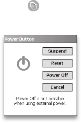
4. Unplug the wall charger.
5. Press the Power button
until the Power Button
menu appears.
6. Select Power Off from
the menu, then tap OK.
7. Place the Field PC in a
safe, dry place.
95
Chapter 10: Caring for Your Field PC

Taking the Field PC out of extended storage. The
battery pack discharges slightly during extended storage
periods. When you are ready to use your Field PC again,
follow these steps so your battery pack runs efficiently:
1. Plug the Field PC into a charger.
2. Charge the battery pack. (To check the battery power
status, tap on the battery icon at the top of
the screen.) Only charge the battery pack in
temperatures between 32°F and 104°F (0°C and
40°C). For best results, charge the battery pack at
room temperature (68°F or 20°C).
Protecting the
touchscreen
Protect the touchscreen from impact, pressure, or
abrasive substances that could damage it. To further
protect the touchscreen, apply one of the adhesive
screen protectors that came with your Field PC.
CAUTION: Be sure to replace the screen protector as
often as the screen protector packaging directs.
To apply a screen protector, follow these steps:
1. Make sure the Field PC screen is free of oils and
dirt. You can wipe it with a microfiber cloth.
2. Peel back the paper liner from the screen protector,
exposing approximately one inch, as shown in the
following image.
96
3. Align bottom corners of the screen protector with the
Field PC screen, sticky side down.
4. Smooth the screen protector while peeling back the
liner, working out air bubbles as you go. Continue
smoothing until the paper liner is removed.
Note: Some air bubbles may still be visible, but they
fade away in a short time. You can use a credit card to
gently push out any excess air.
Protecting the Field PC
against mechanical shock
The Field PC is designed for protection from mechanical
shock. It can be dropped from up to five feet (1.524m)
onto concrete. Shock protection is guaranteed only when
the top cap and body molding are securely in place.
97
Chapter 10: Caring for Your Field PC

Battery warnings
WARNING! This device comes with a lithium ion
rechargeable battery pack. To reduce the risk of fire
or burns, do not disassemble, crush, puncture, short
external contacts, or expose the battery pack to fire.
Follow these additional safety guidelines:
Use only battery packs approved for use with this
device.
Do not store or leave your device or battery pack
near a heat source such as a radiator, fireplace, stove,
electric heater, or other heat-generating appliance,
or otherwise expose it to temperatures in excess of
140° F (60° C).
Do not try to open the battery pack.
Do not carry a battery pack in your pocket, purse,
or other container where metal objects (such as car
keys or paper clips) could short-circuit the battery
pack terminals.
Keep the battery pack contacts clean. If they get dirty,
wipe them off with a soft cloth.
Dispose of the battery pack properly. See the section
called Disposing of your Field PC and battery packs
in this manual for instructions.
Do not install the battery pack backwards so that the
polarity is reversed.
Do not connect the positive terminal and the
negative terminal of the battery pack to each other
with any metal object (such as wire).
Do not solder directly onto the battery pack.
Do not place the battery pack in direct sunshine.
In the rare event that the battery pack leaks and fluid
gets into the eye, do not rub the eye. Rinse well with
•
•
•
•
•
•
•
•
•
•
•
98

water and immediately seek medical care.
Dispose of the battery pack properly. See the section
below, Disposing of your Field PC and battery packs
for instructions.
Equipment warnings
WARNING! To reduce the risk of personal injury,
electrical shock, fire or damage to the equipment:
Plug the wall charger into an electrical outlet that is
easily accessible at all times.
Disconnect power from the equipment by
unplugging the wall charger from the electrical outlet
or unplugging the synchronization cable from the
host computer.
Do not place anything on the wall charger cord or
any of the other cables. Arrange them so that no one
may accidentally step on or trip over them.
Do not pull on a cord or cable. When unplugging the
wall charger from the electrical outlet, pull on the
plug, not the cord.
Use only wall chargers intended for the Field PC.
Using
any other external power source can damage your
product and void your warranty.
Using the Field PC in
extreme temperatures
The Field PC operates in ranges from -22° F to 122° F
(-30° C to 50° C). To help your device function properly,
store the device indoors when possible.
•
•
•
•
•
•
99
Chapter 10: Caring for Your Field PC

Other tips:
If the Field PC is exposed to temperatures below
14°F (-10°C ), the device may slow down or the
display backlight may become dim to reduce the
load on the battery power.
Extremely low or high temperatures may prevent the
battery pack from charging. Charge the battery pack
in temperatures between 32°F and 104°F (0° C and
40° C). For best results, charge the battery pack at
room temperature (68°F or 20°C)
Cleaning the Field PC
This section explains how to clean
the touchscreen
the communications module (area housing the USB
port, DC jack, and serial port)
the speaker or microphone
the stylus slot
the display bezel
CAUTION: Always make sure the top cap is on and
screws are fitted tightly before you begin cleaning your
Field PC.
Touchscreen. To clean the touchscreen, follow these
steps:
1. Press the power button briefly to suspend the device.
2. If you applied a protector to the touchscreen,
carefully remove it.
3. Apply water or a mild cleaning solution such as
Windex® or 409® to a microfiber cloth and gently wipe
off the touchscreen. Other approved cleaners include
Citrus Wonder® and Citrus All Purpose Cleaner®.
•
•
•
•
•
•
•
100

CAUTION: Do not use tissues, paper towels, or harsh
cleaning agents to clean the touchscreen.
3. If you used a cleaning solution, rinse the touchscreen
with water and dry it with a microfiber cloth.
4. Press the power button to resume the device.
CAUTION: Long exposure to the following solutions may
damage your device:
pine oil
oil based paint
automotive brake cleaner
isopropyl alcohol
carburetor cleaner
In case the device is exposed to one of these solutions,
wipe it off with a mild cleaning solution.
Case overmolding. Clean the rubber-like overmolding
that surrounds the case with a cloth and a mild cleaning
solution like 409 or Citrus Wonder. After you are done
cleaning, rinse the device with water.
Communications module (area housing the
USB port, DC jack, serial port). To clean the
communications module, run it under a faucet. Use a
soft toothbrush or toothpick to clean out any remaining
dirt.
Speaker and microphone. If debris gets in the speaker
or microphone, use a soft bristle brush to remove it. Do
not insert any object into the speaker or microphone
holes.
Stylus slot. Rinse the stylus slot with water.
Display bezel. If the edge under the bezel gets dirty, use
a microfiber cloth to remove the debris. Do not remove
the bezel.
•
•
•
•
•
101
Chapter 10: Caring for Your Field PC

Repairing the Field PC
If the Field PC is in need of repair, call your service center
for a Return Materials Authorization number (RMA).
IMPORTANT: Do not attempt to service the device
yourself. This action voids the warranty.
Disposing of the Field PC
and battery packs
This product must not be disposed of with
municipal waste. It is your responsibility
to dispose of your waste equipment by
handing it over to a designated collection
point for the recycling of waste electrical
and electronic equipment. If you cannot
find a location, contact the manufacturer for
information about disposal.
The lithium-ion battery packs for your Field PC are
recyclable. Avoid placing them in the trash or municipal
waste system.
To find the nearest battery recycling center in the USA,
visit the Rechargeable Battery Recycling Corporation’s
website at www.rbrc.org/call2recycle/index.html or call
1-800-8-battery.
The Field PC contains no mercury or cadmium.
102

User’s Guide
Troubleshooting
and Service
Tips
Troubleshooting tips
Preparing for a service center call
11

104
This chapter includes some basic troubleshooting tips. It
also explains what you need to do before you call your
service center for a repair.
Answers to questions about Windows Mobile® may be
available through the help files on your device or on the
Windows Mobile website from Microsoft® at
www.Microsoft.com/mobile. If you cannot find answers
to your questions through these methods, contact your
service center. (See the section in this chapter called
Preparing for a service center call.)
Troubleshooting tips
This section provides solutions for the following issues:
1. The battery pack will not charge fully.
2. The touchscreen responds inaccurately to stylus taps.
3. The screen does not calibrate correctly or completely.
4. The Field PC runs slowly.
5. The Field PC drops its ActiveSync® connection.
6. The Field PC locks up.
Issue 1: The battery pack will not charge to 100% or to
“0 mAh Consumed”.
Solutions: Try discharging the battery pack completely.
You can turn off all auto-suspend and auto-backlight
timers to drain the battery pack more quickly. Once the
battery pack is fully discharged, try charging it again.
Chapter 11
Troubleshooting
and Service Tips
Chapter 11: Troubleshooting and Service Tips
105
If the battery pack does not charge to full, try repeating
the full discharge and charge cycle a few more times.
If the battery pack still does not charge to full, try using
a different battery pack to confirm that the problem is
specific to the original battery pack.
Only charge the battery pack in temperatures between
32°F and 104°F (0°C and 40°C). For best results, charge
the battery pack at room temperature (68°F or 20°C).
Issue 2: The touchscreen does not respond accurately to
stylus taps.
Solutions: Try recalibrating the touchscreen. (See the
section in Chapter 3 called Using the touchscreen.)
If the device is not responding to stylus taps at all and
you are on the Today screen, look to see if the device is
locked. To unlock the device, press the Unlock soft key
on the screen.
If the device is unlocked but the stylus continues to
respond inaccurately, close all open programs and reset
the device. (See Chapter 5 for instructions.)
Issue 3: During calibration, the screen does not respond
to stylus strokes or does not complete the calibration
process.
Solutions: Check to see if there is something stuck
underneath the bezel. Use a microfiber cloth to remove
any excess debris. Also check to see if there is damage or
wear on any area of the touchscreen. In case of damage,
contact your service center.

106
Issue 4: The Field PC runs slowly.
Solutions: It is possible that you have too many
programs running. Try closing any programs you are not
using. To view and close running programs, follow these
steps:
1. Tap on the Applications Manager icon. The
Applications Manager window appears.
2. Tap on the Running Programs tab in the Applications
Manager window.
3. Select a program and tap Stop. This closes the
program.
Issue 5: My Field PC quickly drops its ActiveSync
connection to my desktop computer.
Solutions: Firewall programs sometimes cause
ActiveSync connection problems. In these cases, the
firewall sees the Field PC as a strange and possibly
hostile computer and prevents the device from
connecting to the desktop computer.
To allow the mobile device to connect to your desktop
computer, follow these steps:
1. Use the serial cable to connect your device to the
desktop computer. Follow the ActiveSync wizard
instructions.
2. If your firewall application brings up a warning
message asking whether you want to allow a
connection, check the option to allow the connection
and click “Yes”.
Note: If the warning message above does not
appear when you try to connect to the desktop
computer but the device is still being dropped,
contact your service center.
Chapter 11: Troubleshooting and Service Tips
107
Issue 6: The Field PC locks up.
Solution: To reset the device, press and hold the Power
button for 10 seconds or until the screen goes dark. The
device turns on again after a few seconds.
Preparing for a service
center call
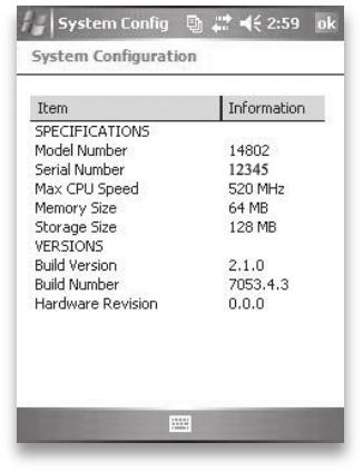
When you contact a service center, you are asked to
identify your device. Your device serial number and other
identification information can be found by following
these steps:
1. Tap Start > Settings. The Settings window appears.
2. Tap the System tab.
3. Choose System Config. The System Configuration
window appears, listing the information you need for
the service center.
108

User’s Guide
12
Information for
Software
Developers
Programming documentation
Software Development Kit (SDK)
Software development tools

Programming
documentation
Documentation for programming Microsoft Windows
Mobile® can be found at:
http://msdn.Microsoft.com/mobility/Windowsmobile/
default.aspx. This website from Microsoft is designed for
software programmers.
Software Development Kit
(SDK)
Your Field PC uses the standard SDK Microsoft provides.
More information about the Windows Mobile 5.0 SDK for
Pocket PC devices can be found at:
http://msdn2.microsoft.com/en-us/windowsmobile/
default.aspx
Software development
tools
Microsoft recommends Visual Studio® 2005 for Windows
Mobile development. This tool gives users the ability
to create “native” code so they can debug and test in a
Chapter 12
Information for
Software
Developers
110
close relationship with the device. Older development
tools allow you to compile applications, but they do
not offer device connectivity options for more complete
development and verification tasks.
More information about Visual Studio 2005 and other
tools from Microsoft can be found at:
http://msdn.Microsoft.com/mobility/Windowsmobile/
howto/Windowsmobile5/default.aspx
Chapter 12: Information for Software Developers
111
112

User’s Guide
Appendix
A
Product
Specications

Appendix A
Product
Specications
Features Your Field PC
Operating System Microsoft® Windows Mobile® 5.0
Processor Intel® XScale® PXA270, 520 MHz
Memory 128 MB low-power RAM
Primary Storage Internal solid-state 256 or 512
MB Flash
Secondary Storage Internal solid-state 128 MB Flash
(portion reserved for OS)
Display 3.5” (89 mm) QVGA active matrix
color TFT transflective LCD with LED
backlight; 240 x 320 pixels
Touchscreen Sealed, resistive, pressure sensitive
CF and SD Card
Slots
Compact Flash (Type I or Type II),
Secure Digital (SD or SDIO); each
card slot
provides 3.3 V; user accessible,
sealed
Keyboard Four-way directional button,
standard key functions, LED backlit
keys
Physical 6.5” length x 3.5” wide x 1.7” thick
(165 x 89 x 43 mm), 17 oz (482 g);
magnesium case with elastomer
overmold
114

Features Your Field PC
Operating
Temperature for
Devices without
Internal Bluetooth
-22° to 122°F (-30° to 50°C)
Operating
Temperature for
Devices with
Internal Bluetooth
-4° to 122°F (-20° to 50°C)
Storage
Temperature
-22° to 140°F (-30° to 60°C)
Battery Charging
Temperature
32° to 104°F (0° to 40°C)
IP67 Sealed rating, waterproof and
dustproof
MIL-STD-810F Water, humidity, sand and dust,
vibration, altitude, shock, high
temperature, low temperature,
temperature shock
Shock Absorbency Multiple drops onto concrete from
5 ft (1.5 m) through temperatures
ranging from -22 to 122° F (-30 to
50° C)
Batteries Intelligent, rechargeable Li-Ion
battery pack, 14 W-hr (nom.)
Communications
Module
Serial port 9-pin D-sub connector,
USB Host (Mini A), USB Client
(Mini B), 12 VDC jack for power
input and battery charging
Appendix A: Product Specications and Pinouts
115

Features Your Field PC
COM 1 Port 9-pin D-sub connector; full modem
control signals, 5 V @ 200 mA
available on DTR pin 4; controlled
by DTR signal; conformal coated
Current Limits CF card slot: 3.3 V; SD card
slot: 3.3 V; USB Host: 5 V; 9-pin
D-sub connector: 5 V on DTR
line; recommended maximum
combined output current: 500 mA;
short circuit protected
Power Voltage +12 VDC; Range +10 10-20
VDC; Current: Max 12 V @ 850 mA;
reverse polarity protection; over
voltage protection; auto shut off
Wireless
Communication
Options
Integrated Bluetooth or Bluetooth-
supported with CF or SD Bluetooth
card; Wi-Fi supported; wireless
cellular modem
Internal Clock Battery-backed real time clock
Development
Environment
SDK for Windows Mobile® for
Embedded Visual C++® version
4.0 and Visual Studio® 2005
Enunciators External power/charge LED and
notification LED; other enunciators
on system tray
Certifications FCC Class B, European CE Mark
116
9-pin serial port pinouts
Pin # Description
1 Data Carrier Detect (DCD) Input
2 Receive Data (RCD) Input
3 Transmit Data (TXD) Output
4 Data Terminal Ready (DTR) Output
5 Ground (GND)
6 Data Set Ready (DSR) Input
7 Request To Send (RTS) Output
8 Clear To Send (CTS) Input
9 Ring Indicator (RI) Input
Appendix A: Product Specications and Pinouts
117
118

User’s Guide
Appendix
B
Certications
and Regulatory
Information
Regulatory Information
CE marking

Regulatory information
This equipment has been tested and found to
comply with the limits for a Class B digital device,
pursuant to Part 15 of the FCC Rules. These limits are
designed to provide reasonable protection against
harmful interference when the equipment is used in a
commercial or residential environment. This equipment
generates, uses, and can radiate radio frequency energy
and, if not used in accordance with the reference guide,
may cause harmful interference to radio communication.
If this equipment does cause harmful interference to
radio or television reception, which can be determined
by turning the equipment off and on, the user is
encouraged to try to correct the interference by one or
more of the following measures:
Reorient or relocate the receiving antenna.
Increase the separation between the equipment and
receiver.
Connect the equipment into an outlet on a circuit
different from that to which the receiver is
connected.
Consult the dealer or an experienced radio/TV
technician for help.
•
•
•
•
Appendix B
Certications and
Regulatory
Information
120

This device complies with Part 15 of the FCC Rules.
Operation of this equipment is subject to the following
two conditions:
1. The device may not cause harmful interference.
2. This device must accept any interference
received, including interference that may cause
undesired operation.
CAUTION: Only approved accessories may be used
with this equipment. In general, all cables must be high
quality, shielded, correctly terminated, and normally
restricted to two meters in length. Wall chargers
approved for this product employ special provisions to
avoid radio interference and should not be altered or
substituted.
CAUTION: Changes or modifications to the Field PC that
are not expressly approved by the manufacturer could
void the user’s authority to operate the equipment.
CE marking
Products bearing the CE marking comply with the
EMC Directive (89/336/EEC), the R&TTE Directive
(1999/5/EC), and the Low Voltage Directive (73/23/EEC)
issued by the Commission of the European Community.
CE compliance of this device is valid only if powered
with/by a CE-marked wall charger provided by the
manufacturer. Compliance with these directives implies
conformity to the following European Norms (in
parentheses are the equivalent international standards
and regulations):
EN 55022 (CISPR 22)—Electromagnetic Interference
EN 55024 (IEC 61000-4-2, 3, 4, 5, 6, 8, 11)—
Electromagnetic Immunity
•
•
Appendix B: Certications and Regulatory Information
121

122
EN 61000-3-2 (IEC 61000-3-2)
—Power Line Harmonics
EN 61000-3-3 (IEC 61000-3-3)
—Power Line Flicker
EN 60950 (IEC 60950)
—
Product Safety
ETS 300 328-2
—Technical Requirements for 2.4 GHz
Radio Equipment
EN 301 489-1, -17
—General EMC Requirements for
Radio Equipment
CAUTION: Although the radiated output power of this
device is below the FCC radio frequency exposure limits,
the device should be used in ways that minimize the
potential for human contact during normal operation.
The possibility of exceeding the FCC radio frequency
exposure limits can be avoided by minimizing operation
of the device in close proximity to the human body.
Metallic body accessories are not permitted and 1.5
cm spacing between the device and the body must be
maintained to satisfy RF exposure.
This device must not be co-located or operating in
conjunction with any other antenna or transmitter.
The telecommunication functions of this device may be
used in the following EU and EFTA countries: Austria,
Belgium, Bulgaria, Cyprus, Czech Republic, Denmark,
Estonia, Finland, France, Germany, Greece, Hungary,
Iceland, Ireland, Italy, Latvia, Liechtenstein, Lithuania,
Luxembourg, Malta, Netherlands, Norway, Poland,
Portugal, Slovak Republic, Romania, Slovenia, Spain,
Sweden, Switzerland, and United Kingdom
•
•
•
•
•

User’s Guide
Standard
Warranty Terms
and Conditions
Appendix
C

Limited Product Warranty
Juniper Systems, Inc. (“JS”) warrants that the Field
PC/Field PCs shall be free from defects in materials and
workmanship, under normal intended use, for a period
of 12 months from the date of shipment. The Field PC
can be warranted up to 5 years (including the standard
warranty period) through the purchase of an extended
warranty. JS warrants that the following items shall be
free from defects in materials and workmanship, under
normal intended use, for a period of ninety (90) days
from the date of shipment:
battery packs,
media containing the Field PC programs,
desktop computer programs,
user documentation, and
accessories.
Extended warranties apply only to the Field PC, not
battery packs, media containing the Field PC programs,
desktop computer programs, user documentation, and
accessories. Parts that are excessively worn are not
covered under the extended warranty plan. These may
include, but are not limited to, the keyboard elastomer
and switch matrix, hand straps, touchscreens, and
connector modules.
•
•
•
•
•
Appendix C
Standard Warranty
Terms and
Conditions
124
Warranty exclusions
This warranty shall not apply if:
(i) the product has been set up improperly or has been
improperly installed or calibrated,
(ii) the product is operated in a manner that is not in
accordance with the user documentation,
(iii) the product is used for a purpose other than for
which it was designed,
(iv) the product has been used in environmental
conditions outside of those specified for the product,
(v) the product has been subject to any modification,
alteration, or change by or on behalf of customer
(except and unless modified, changed or altered by
JS or under direct supervision of JS),
(vi) the defect or malfunction results from misuse or
accident,
(vii)
the serial number on the product has been tampered
with or removed, or
(viii)
the product has been opened or tampered with
in any way.
This warranty is exclusive and JS will not assume and
hereby expressly disclaims any further warranties,
whether express or implied, including, without limitation,
any warranty as to merchantability, fitness for a particular
purpose, non-infringement or any warranties arising
from the course of performance, dealing, or usage of
trade. JS specifically makes no warranties as to the
suitability of its products for any particular application. JS
makes no warranties that
its products will meet your requirements or will work
in combination with any hardware or applications
software products provided by third parties,
•
Appendix C: Standard Warranty Terms and Conditions
125
the operation of its products will be uninterrupted or
error free, or
all defects in the product will be corrected.
JS shall not be responsible for software, firmware,
information, or memory data contained in, stored on, or
integrated with any products returned to JS for repair,
whether under warranty or not.
Remedy
In the event a defect in materials or workmanship is
discovered and reported to JS within the specified
warranty period, JS will, at its option, repair the defect
or replace the defective part or product. Replacement
products may be new or reconditioned. JS warrants any
replaced or repaired product for a period of ninety (90)
days from the date of return shipment, or through the
end of the original warranty period, whichever is longer.
Limitation of Liability
To the fullest extent allowed by law, the obligation
of JS shall be limited to the repair or replacement of
the product. JS shall in no event be liable for special,
incidental, or consequential, indirect, special or punitive
damages of any kind, or for loss of revenue or profits,
loss of business, loss of information or data, or other
financial loss arising out of or in connection with the
sale, installation, maintenance, use, performance, failure,
or interruption of any product. Any responsibility and/
or liability of JS shall, in connection with a warranted
product, be limited in the maximum amount to the
original purchase price.
•
•
126
Warranty Repairs
To obtain repair or service on the Field PC, contact your
authorized repair center within the applicable warranty
period to receive a Return Material Authorization (RMA)
number. Repairs returned without proper authorization
may acquire an additional handling fee and/or delay
in the repair. The customer is responsible to prepay all
shipping costs when sending equipment to a repair
center. JS will return the repaired equipment by the
same method it was received with costs of shipping
prepaid.
Governing Law
This warranty is governed by the laws of Utah, and
excludes the United Nations Convention on Contracts
for the International Sale of Goods. The courts of Utah
shall have exclusive personal jurisdiction in case of
any disputes arising out of or in connection with this
warranty.
Services and Materials Provided Under Warranty
Analysis of problem by service technician
Labor and materials required to fix defective parts
Functional analysis performed after repair
Repair turnaround within 10 working days of receipt
unless special circumstances exist
Shipping costs to return device to customer
•
•
•
•
•
Appendix C: Standard Warranty Terms and Conditions
127
128
User’s Guide
Index

Index
130
Symbols
12V DC jack 5
9-pin serial port 5
9-pin serial port pinouts 117
A
About 66
About window 10
AC adapter. See Wall charger
Accessory attachment points 4
ActiveSync
as an application in the Programs menu 62
configuring to use with a Bluetooth device 84
connecting as a guest 53
creating a connection 12
creating a device name for multiple partnerships 52
deleting a partnership 54
establishing a partnership 12
installing the latest version 11
synchronization settings 51
transferring files to and from the Field PC 54
using to explore the Field PC 55
using to install applications on the Field PC 56
ActiveSync connection
reestablishing 51
what to do if it drops consistently 106
Adjusting the backlight 3
Anatomy of the Field PC 4. See also Field PC, anatomy of
Applications. See Programs
Applications Manager button
functions 14
using to close running programs 41
Applications Manager status icon
function 33
image 33
using to stop running programs 41
B
Backing up data. See Copying
to a CF or SD card 45
to a desktop computer 44
Backlight
dimming 35
keyboard backlight stays on after power off 39
settings option 66
timer. See Backlight timer
turning off 35
Backlight timer
about 35
adjusting 35
Battery. See Battery pack
Battery contacts 8, 23
Battery door. See Battery door latch
removing 8
unlocking 8
Battery door latch
locking 8, 24
Index
131
unlocking 8
unlock position 23
Battery door tabs 8, 23
Battery icon 24
Battery pack
charging 9, 115
removing while the device is plugged in 24
replacing 22
specifications 115
Battery power, preserving 17, 39
Beaming. See OBEX (Object Exchange profile)
Beam settings option 66
Bluetooth
cards not recognized by integrated Bluetooth model 82
creating a partnership 73
Dial-Up Networking profile 82, 86
using a cell phone to connect to the Internet 86
using a cordless modem to connect to the Internet 88
Done soft key 72
dongle 85
drivers 70
entering an assigned passkey 74
if no passkey is needed 74
making the Field PC discoverable 73
Menu soft key 72
Object Push Profile (OPP) 82
Partnership Settings screen 75
peripheral devices
communicating with a Bluetooth dongle 85
profiles
Dial-Up Networking (DUN) 82
132
Human Interface Device (HID) profile 82, 89
OBEX 90
Object Push Profile (OPP) 82
relationship to drivers 82
Serial Port Profile 82
those supported by Microsoft drivers 70
Serial Port Profile
configuring ActiveSync on a desktop computer 84
using to communicate with another device 83
using to print 85
Serial Port Profile (SPP) 82
setting up an incoming COM port 79
setting up an outgoing COM port 76
toggle bar 71
turning on or off 72
using a Field PC with integrated Bluetooth 70
virtual COM ports 75
using to connect with a GPS receiver 75
Bluetooth card 24
if you installed new drivers 82
Bluetooth settings option 66
Brightness settings option 66
Button functions
customizing 15
identifying 14
list 14
Buttons
customizing functions. See Customizable buttons
settings option 66
using to restore all factory defaults. See restoring all
factory defaults
Index
133
C
Cable routing channel 5
Calculator application 62
Calendar 61
Calibrating the device 9
Calibration
what to do if the device does not completely calibrate
105
Case overmolding 101
Celll phone dial-up connection 86
Certificates settings option 66
Certifications
list 116
CF card. See Compact Flash card
CF card slot. See Compact Flash card slot
Charge indicator 33
Charge LED
about 22
flashing 9
Charging the battery pack 9
Cleaning the Field PC 100
Clock and Alarms 66
Closing running programs
to replace battery pack 22
to reset the device 40
COM 1 Port 116
Communications module
cleaning 101
location on Field PC 5
134
specifications 115
Compact Flash card
copying data from 26
if the card is not recognized 26
installing 26
reinserting or changing 26
Compact Flash card slot
accessing 25
compatible devices 24
location on Field PC 5
product specifications 114
Connections settings option 66
Contacts application 61
Context menu 20
Context menu button
functions 15
Copying
from a peripheral device 26, 47
to a CF or SD card 45
to a desktop computer 44
using the stylus 20
Cordless modem
using with Bluetooth to connect to the Internet 88
Creating an ActiveSync connection 12
Creating a name for the Field PC 9
Current Limits 116
Customer service. See service center, preparing for a call
Customizable buttons 15
Customizing button functions 15
Cutting 20
Index
135
136
Cutting items to paste 20
D
DC jack 9. See also 12V DC jack
Destination folder 27
Device. See Field PC
Device ID tab 10, 52
Device name 52
creating 10
Dial-Up Network (DUN) profile
using a cell phone to connect to the Internet 86
Dial-Up Networking (DUN) profile 82, 86
Dimming the backlight. See backlight, dimming
Discoverable
Bluetooth mode 73
Display
product specifications 114
Disposing of the battery pack. See Recycling the battery pack
Download Agent 63
Drag and drop 20
Drive names
for Field PC 45, 47
Drivers
if you installed new Bluetooth drivers 82
Drivers, Bluetooth 70
Drives 40
E
Enter button
functions 15
Index
137
Entering data 20. See also Input methods
Enunciators 116
Error Reporting settings option 66
Establishing an ActiveSync partnership 12
Establishing basic settings on the device 9
Excel 2
Excel Mobile 63
Exploring files on the Field PC
using ActiveSync 55
using File Explorer 40
Extended caps
instructions for installing 153
F
Factory defaults 19
Field PC
about 2
anatomy of 2
cleaning
display bezel 101
speaker and microphone 101
stylus slot 101
touchscreen 100
in case the device locks up 19
instructions for installing extended caps 153
operating system 114
operating temperature 115
processor 114
protecting against mechanical shock 97
protecting the touchscreen 96
138
repairing 102
resetting 40
shock absorbency specifications 115
storage temperature range 94
storing for less than two weeks 95
storing for more than two weeks 95
taking out of extended storage 95
unlocking 105
what to do if it runs slowly 106
what to do if the Activesync connection drops 106
Field PC Tutorial
As a reference tool 3
File directory in File Explorer 40
File Explorer
about 63
using to back up to a CF or SD card 45
using to explore the Field PC 40
Files, exploring 40
Finding settings 66
firewall application warning 106
Four-way directional button
functions 15
Frequently Asked Questions
if the device locks up 19
G
Games 62
Getting Started Disc
as a reference tool 3
programs 65
Index
139
using to install ActiveSync 11
GPS card 24
GPS receiver
using with virual COM ports 75
green notification LED 18
Guest. See ActiveSync, connecting as a guest
H
Hand strap
reattaching 8, 24
unhooking 8
Help. See on-device help
Help system 2. See also Help
Home button
about 15
Human Interface Device (HID) 82
Human Interface Device (HID) profile 89
I
Icons. See Status icons
Incoming Bluetooth COM port 79
Input method icon 32
Input method menu 32
Input methods
Block Recognizer 32
default input method 32
keyboard 31
Letter Recognizer 32
switching methods 32
Transcriber 32
140
input selector arrow 32
Input settings option
66
Inserting memory cards 3
Installing ActiveSync. See ActiveSync, installing
instructions 11
Installing applications on the Field PC 56
Installing the battery pack 8
Integrated Bluetooth 70
Internal clock
specification 116
Internet connection
using Dial-Up Networking to create a connection 86
IP67 115
K
Keyboard
product specifications 114
Keyboard backlight 39
L
Landscape view 34
LED signals
about 22
charge LED 22
notification LED 22
using to power off the device 18
using to power on the device 39
using to restore factory state 19
Light. See backlight, LED signals
Index
141
Lock
settings option 67
Locked screen 105
Lockup of the device
how to restart the device 19, 40
M
Main screws 5
Manual device reset 19
Measurements of the Field PC 114
Mechanical shock 97
Memory
freeing memory by closing running programs 41
product specifications 114
settings option 67
Memory cards 3. See also Compact Flash card, Secure
Digital card, USB flash drive
Menus settings option 67
Messaging 61
Microphone
cleaning 101
Microsoft Internet Explorer 61
Microsoft Outlook 2
Microsoft support site 44
Microsoft Windows 2000
steps to install ActiveSync 11
Microsoft Windows Vista
instructions for basic file synchronization 10
Microsoft Windows XP
for users of 11
142
Microsoft Word 2
MIL-STD-810F 115
Minimizing a program 41
Mobile Device 55
Modem card 24
Modem Link 63
MSN options 67
Multiple items
copying 27
selecting 20
My Device drive name 45, 47
N
Name
creating for the Field PC 9
Network cards
settings option 67
Notes 63
Notification LED 22
O
OBEX (Object Exchange profile) 70, 90
Object Push Profile (OPP) 82, 90
On-device help
about 43, 62
accessing 43
as a reference tool 2
finding program-specific help 43
Index
143
using Contents 43
using the Search function 43
Opening an item or file 20
Operating system of the Field PC 114
Operating temperature 115
Outgoing Bluetooth COM port 76
Outlook Mobile 2
Overmolding, cleaning 101
Owner Info settings option 67
P
Partnership. See ActiveSync, deleting a partnership;
ActiveSync, establishing a partnership
connecting with another device using Bluetooth 73
Passkey
entering an assigned passkey 74
if no passkey is needed 74
Pasting
to copy files from a peripheral device 27
using the stylus 20
Peripheral devices. See CF card, SD card, USB flash drive
acceptable devices 24
copying data to the Field PC from a peripheral device 26
Physical measurements of the Field PC 114
Pictures & Videos 63
Pinouts 117
Pocket MSN 64
Pop-up menu 27
Portrait view 34
144
Power. See Battery power, Wall charger
specifications 116
Power button
functions 15
using to restore factory defaults 19
Power button functions 17
Power button menu 39
Powering off the device
about 17, 39
instructions 18, 39
Powering on the Field PC 18
PowerPoint 2
Power settings option 67
Preparing for a service center call 107
Printing from the Field PC 85
Product specifications 114
Program Buttons tab 16
Programs
as an option on the Start menu 61
closing running programs 41
on Getting Started CD 65
switching between running programs 42
Programs menu
about 62
applications. See Programs
R
Reassigning a program or shortcut to a button 16
Recalibrating the touchscreen 105
Index
145
Reference tools for users 3
Regional settings 67
Remaining battery capacity (status icon)
function 33
image 33
Remove Programs settings option 67
Repairing the Field PC 102
Replacing the battery pack 3, 22
Resetting the device 18, 40
As a basic task 3
manual reset 19
Restoring factory defaults 19
Rotating the display. See screen, rotating
Running programs
closing 41. See also Applications Manager, programs
on the Start menu 61
S
Screen
does not respond to stylus strokes 105
rotating 34
settings option 67
Screen orientation. See screen, rotating
Screen protector
applying 96
SD card. See Secure Digital card, Secure Digital I/O card
slot
SDIO card slot. See Secure Digital I/O card slot
Seal rating 115
Search application 64
146
Secure Digital card
copying data from 26
installing 26
reinserting or changing a card 26
Secure Digital I/O card slot
acceptable devices 24
accessing 25
location on Field PC 5
product specifications 114
Selecting an item 20
Serial number
using to create a device name 10
Serial port pinouts 117
Serial Port Profile. See Bluetooth, Serial Port Profile
Serial Port Profile (SPP) 82
Service center 107
Settings
as an option on the Start menu 61
Connections menu 66
menus 61
options and locations 66
Personal menu. See Programs
System menu 66
Shock, mechanical 97
Soft keys
about 33
Menu soft key 41
Up soft key 40
Software development tools 110
Software programming
Index
147
documentation 110
SDK 110
Sounds and notifications settings option 67
Speaker
cleaning 101
Speaker status icon 33
Specifications 114
Standard cap
tightening 27
Start menu
about 31, 60
accessing 31
functions 31
programs and utilities 60
Start menu button
function 14
using to access Start menu 31
Start menu icon 31
Status icons
about 33
Applications Manager 33
charge indicator 33
finding additional icons 33
functions 33
remaining battery capacity 33
speaker. See Status icons
Storage capabilities 114
Storage temperature 115
Storing the device by powering off 17
148
Stylus
about 19
functions 19
like left button of computer mouse 19
like right button of computer mouse 19
location on Field PC 5
responds inaccurately after recalibration 105
Stylus slot
cleaning 101
location on Field PC 5
Stylus strokes
no screen response during calibration 105
Suspending the device 17
as compared to powering off the device 17, 38
if the device suspends while charging 9
instructions 17, 38
to replace the battery pack 22
while the device is charging 17
System Configuration screen 53
T
Tasks 64
Temperature
battery charging specs 115
operating 115
storage 115
Terminal Services Client 64
Tightening the top cap
torque specs 27
Timer. See Backlight timer
Index
149
Today screen
about 30
as a part of the Start menu 60
locking the device 30
unlocking the device 30
Today settings option 67
Top cap
designed to protect 25
removing 25
torque specs for tightening 27
Top cap screws
location on Field PC 5
removing 26
tightening 27
Torque specs for the standard cap 27
Touchscreen
calibrating 21
checking for damage or wear 105
cleaning 21, 100
if the stylus responds inaccurately 21, 105
product specifications 114
protecting 20
Transferring files. See Copying; ActiveSync, transferring
files to and from the Field PC
Troubleshooting tips 104
calibration is incomplete 105
CF or SD card is not recognized 26
Field PC drops ActiveSync connection 106
Field PC runs slowly 106
touchscreen responds inaccurately 105
150
Turning off the backlight. See Backlight, turning off
U
Unlocking the device 105
Unlock position 23
Upcoming appointments 30
Up soft key 40
USB Client (mini B)
location on Field PC 5
using to create an ActiveSync connection 12
USB communications cable
Using to create an initial ActiveSync connection 12
Using to reestablish an ActiveSync connection 51
USB devices 25
compatability with Windows Mobile 5.0 25
installing 25
USB flash drive
Copying data to the Field PC 26, 47
Using with the USB Host 25
USB Host (mini A)
acceptable devices 24
location on Field PC 5
using to create an ActiveSync connection 12
USB mini-to-full size adapter 25
User Documentation CD 3
Using programs installed on the Field PC 3
Using the Field PC 3
V
Virtual COM ports for Bluetooth 75
Index
151
W
Wall charger
assembling 9
using to charge battery pack 9
Wall charger plug 9
Warning dialog
for powering off 18
White space 27
Windows 2000
for users of 11
Windows applications. See Windows Mobile 5.0
Windows Media Player 61
Windows Mobile
compatible with applications 2
Use with Microsoft Outlook 2
Windows Mobile 5.0
ActiveSync version requirement 2
compatibility with Windows applications 2
product specifications 114
Windows Mobile Device Center 11
how to download 50
Windows Vista
how to install Windows Mobile Device Center 50
synchronization options 11
Windows XP
for users of 11
Wireless communication options 116
Word. See Microsoft Word
152

Installation
Instructions
Ultra-Rugged Field PC
Extended Caps
Our extended caps maintain the full ruggedness
of the Field PC while allowing you to use CF or SD
peripheral devices. This booklet explains how to install
each cap and also how to mount an external device
like a GPS receiver on your Field PC.
Before You Begin
• Maximum card lengths for each cap are listed on
page 3. To avoid damaging your Field PC, refer to
them before inserting a card.
• SeetheTableofContentstondinstructionsfor
installingyourspecicextendedcap.

2
Package Contents
Communication Cap:
• Foam pads in different sizes
Universal, Optical, and Data Acquisition
(DAQ) Caps:
• Foam pads in different sizes
• Seal adapter plate and screws
• Card pull tabs
• Clear CF card spacer
Required Tools
• #1 Phillips screwdriver
• If you are mounting an external device, you need a
razor blade or sharp knife

3
Table of Contents
Communication Cap .................................................4
Universal, Optical, and Data Acquisition (DAQ) Caps
..6
Mounting an External Device .................................10
Maximum Card Lengths
The maximum total card length for each cap is
listed below.
CAUTION: Using cards that exceed the maximum
lengths listed above may damage your Field PC
and void the warranty.
Communication Cap 2.75 inches (70 mm)
Universal Cap 3.8 inches (96.5 mm)
Optical Cap 3.5 inches (89 mm)
Data Acquisition Cap 1.43 inches (36.4 mm)
Communication Cap
This section explains how to install the
Communication Cap. For instructions on installing the
Universal, Optical, and Data Acquisition (DAQ) caps,
see the next section.
4
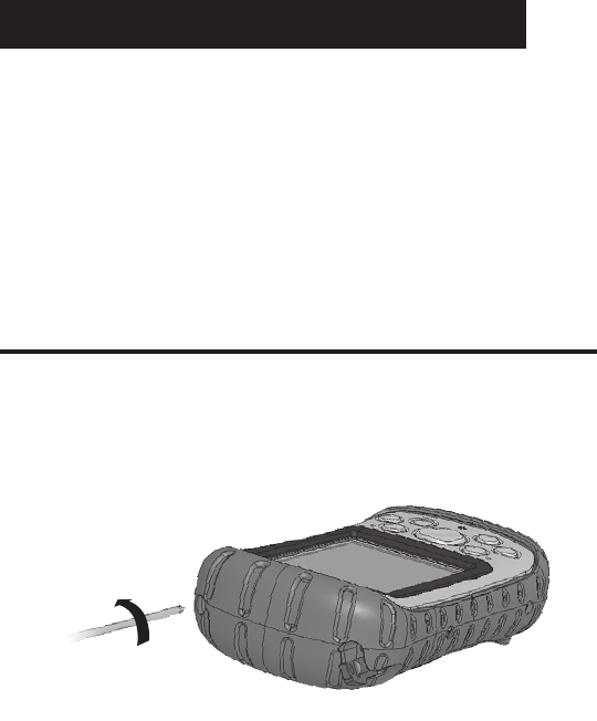
1. Use a #1 Phillips screwdriver to loosen the
captured top screws on the Field PC. Remove the
standard cap.
3. Tighten the Communication Cap screws
untiltheyarermlyinplace.Toproperly
seal the cap, apply an extra ¼ to ½
turn after the screws become
hard to turn.
2.
Insert your card. To keep your
card securely in its slot, cushion
it by placing small or medium-
sized foam pieces inside the
top of the cap. Insert enough
foam into the cap so that
when you slide the cap back
onto the Field PC with little
pressure, a ¼ inch (6 mm)
gap remains between the cap
and the Field PC, as shown.
¼ in. (6 mm) gap
5
Universal, Optical, and DAQ Caps
1. Use a #1 Phillips screwdriver to loosen the captured
top screws on the Field PC. Remove the standard
cap.
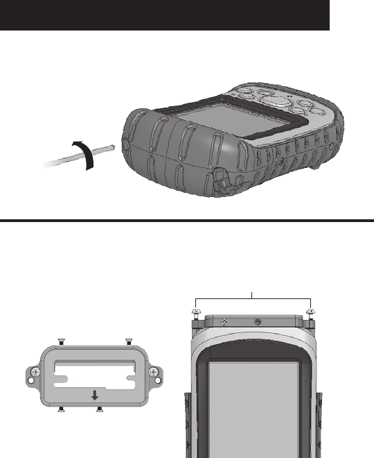
2. Place the seal adapter plate onto the Field PC with
the arrow pointing towards the display. Tighten the
two adapter plate screws.
6
adapter plate screws
seal adapter plate
This section tells you how to insert your card(s)
properly. For memory cards, see step 3. For medium
or large CF cards, see step 4. For any other card
types, insert your card(s) and skip to step 5.
CAUTION: Before inserting a card, make sure the
four side screws on the seal adapter plate are backed
out 1/8 inch as shown in the rst image in step 2.
3.
If you are inserting an SD or CF memory card, make
iteasiertoremovebyrstplacingacardpulltab
onto the card. Insert the card
.
Type I CF card spacer
4. A Type I CF card is thinner than a Type II card,
so it needs a spacer to keep the card in place.
Before you insert a Type I CF card (1/8 inch or
3mmthick),rstinsertthecardspacerin
the CF card slot closest to the front of the
Field PC. If you are inserting a Type II
CF card (¼ inch or 5.5 mm thick), do
not insert the spacer card. Insert
the card.
7
¼ inch (6 mm) gap
6.
If you inserted a camera SD
card, insert large foam pieces
inside the top of the cap to keep
the camera in place. Stack
enough foam in the top of the
cap so that when you slide the
cap into place with little pres-
sure, a ¼ inch (6 mm) gap re-
mains between the cap and the
Field PC. This gap closes when
you secure the
cap in step 8.
8
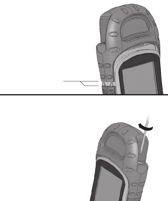
5. Once you have inserted your card(s), tighten the
four small side screws until the top of each screw
isushwiththeoutside
of the gasket piece.
CAUTION:
Before removing
an inserted card,
loosen the four small
side screws by 1/8 inch
(3 mm).
8.Tightenthecapscrewsuntiltheyarermlyin
place. If you inserted foam into the
capinstep6,rstpressdownon
the cap so the screws engage.
To properly seal the cap, apply
an extra ¼ or ½ turn after the
screws become hard to turn.
Note: Even if a small gap
remains between the
extended cap and the body
molding, the Field PC is
fully sealed.
7. If you are using the Data
Acquisition (DAQ) Cap, plug
the wiring harness into the
inserted Data Acquisition
CF card.
9

Mounting an External Device
Overview
The Field PC features a convenient cable channel that
hides cables attached to an external device you mount
on the Universal, Optical, or Data Acquisition Caps.
External devices might include an external RS-232
sensor (such as a GPS receiver) or a USB device.
This section explains how to insert a cable in the cable
channel and how to mount the external device onto the
extended cap. These instructions assume you have
already installed your extended cap onto the Field PC.
10
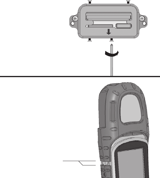
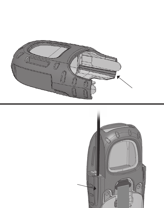
1. Turn off the Field PC and
remove the extended cap,
bottom hand strap latch, battery
door, and battery pack. Leave
the serial adapter plate in place.
Carefully remove the four side
screws on the body molding
and slide off the body molding
about 1 inch (2.5 cm).
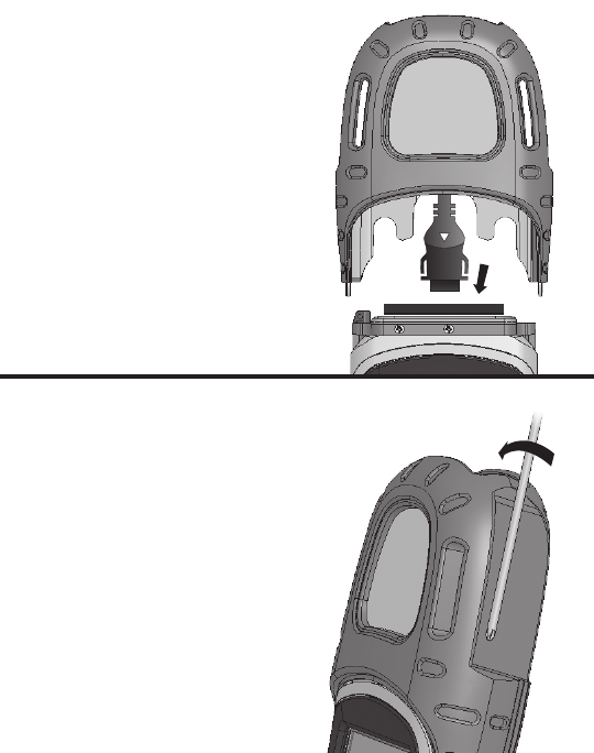
2. Thread the sensor cable along the cable
channel and out through the body
molding.
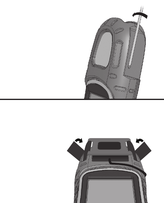
3. With the cable in place, slide
the body molding into place
and tighten the four side
screws. Replace the
battery pack, battery door,
and hand strap.
11
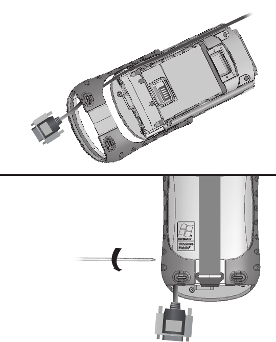
5. Make sure the seal adapter plate is properly
installed.
CAUTION: The seal adapter plate must be
installed to seal the Field PC.
If you have not already installed the seal adapter
plate onto your Field PC, see steps 2–4 of the
previous section for instructions.
12
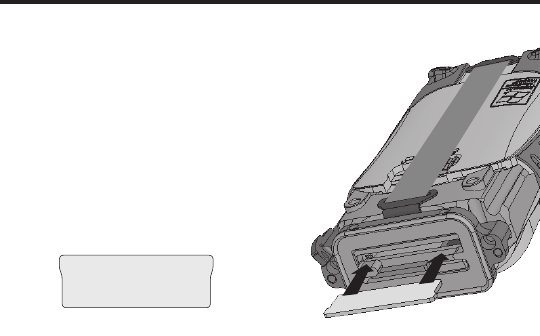
4. Connect the sensor connec-
tor to the 9-pin serial port or
USB host port.
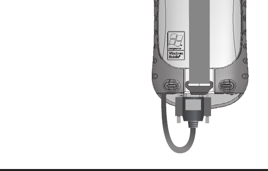
7. Slide the extended cap onto
the Field PC and push the
sensor cable through the
incision you made so that
the cable exits out of the
top of the cable channel.
Note: The incision does
not affect the seal of the
Field PC.
6. To give the cable an exit through the extended cap,
cut the thin rubber overmolding on the extended cap
along the entire scribe line using a razor blade or
sharp knife.
make
cut here
13
incision
8.Tightenthecapscrewsuntiltheyarermlyin
place. To properly seal the cap,
apply an extra ¼ to ½ turn after
the screws become hard to
turn.
14
9. Mount the sensor on the front of the extended
cap and secure it with a strap. Note: An optional
sensor mounting strap is available
for purchase.
The gure here
shows a GPS
antenna mounted
on the Universal
Cap and secured
with the sensor
mounting strap.

P/N 15147-01
© Copyright 11/06. Juniper Systems, Inc. All rights reserved.
Information subject to change without notice.
Selection Chart
CF & SDIO cards
Wi-Fi X X X
Cellular Modem X X X
Bluetooth (Class 1 or 2) X X X
Digital Camera X X
GPS Receiver X
Bar Code Scanner X
RFID Scanner X X
NI CF-6004 X
CF Memory Card X X X
SDIO Memory Card X X X X
COMMUNICATION
UNIVERSAL
OPTICAL
DATA ACQUISITION