KAPSCH TRAFFICCOM CANADA 802295A Non-multilateration LMS transmitter and receiver User Manual Operator and Maintenance Manual
KAPSCH TRAFFICCOM CANADA INC. Non-multilateration LMS transmitter and receiver Operator and Maintenance Manual
Contents
- 1. Operations and Maintenance Manual
- 2. Users Manual
Operations and Maintenance Manual

Confidential UM 360463-202 Revision: A12 (Draft)
© Kapsch TrafficCom Canada Inc. 2014
These drawings and specifications contain confidential and proprietary information and are the property of Kapsch TrafficCom Canada Inc. and are issued in strict
confidence and will be kept confidential and used solely for the purpose intended and for no other purpose and shall not be transmitted, reproduced, copied, and/or
used as the basis for manufacture or sale of apparatus unless otherwise agreed to in writing by Kapsch TrafficCom Canada Inc.
FILE: MPR2_OPERATIONS_AND_MAINTENANCE-MANUAL_REV A12.DOCX 05/08/2014 11:24
Kapsch TrafficCom
JANUS® MULTI-PROTOCOL READER VER. 2
OPERATOR AND MAINTENANCE MANUAL
QMS EDITION - ISO9001:2008
DOCUMENT: UM 360463-202
REVISION:A12 (Draft)
DATE: May 8, 2014
Kapsch TrafficCom
6020 AMBLER DRIVE
8201 GREENSBORO DRIVE , SUITE 1002
MISSISSAUGA, ON L4W 2P1
1. MCLEAN, VA 22102
TEL: (905) 624-3025
2. TEL: (703) 885-1976
FAX: (905) 624-4572
3. FAX: (703) 790-9100

Confidential UM 360463-202 Revision: A12 (Draft) Page 2 of 291
© Kapsch TrafficCom Canada Inc. 2014
These drawings and specifications contain confidential and proprietary information and are the property of Kapsch TrafficCom Canada Inc. and are issued in strict
confidence and will be kept confidential and used solely for the purpose intended and for no other purpose and shall not be transmitted, reproduced, copied, and/or
used as the basis for manufacture or sale of apparatus unless otherwise agreed to in writing by Kapsch TrafficCom Canada Inc.
FILE: MPR2_OPERATIONS_AND_MAINTENANCE-MANUAL_REV A12.DOCX 05/08/2014 11:24
Kapsch TrafficCom
This Page Intentionally Left Blank

Confidential UM 360463-202 Revision: A12 (Draft) Page 3 of 291
© Kapsch TrafficCom Canada Inc. 2014
These drawings and specifications contain confidential and proprietary information and are the property of Kapsch TrafficCom Canada Inc. and are issued in strict
confidence and will be kept confidential and used solely for the purpose intended and for no other purpose and shall not be transmitted, reproduced, copied, and/or
used as the basis for manufacture or sale of apparatus unless otherwise agreed to in writing by Kapsch TrafficCom Canada Inc.
FILE: MPR2_OPERATIONS_AND_MAINTENANCE-MANUAL_REV A12.DOCX 05/08/2014 11:24
Kapsch TrafficCom
FCC License Notice:
This equipment emits RF signals. In order to operate this equipment the customer
must obtain a separate FCC Part 90 Site license for each location. In addition, the
FCC ID component identification JQU802295 must appear on a label on the front
of the RF Modules installed in these Readers.
NOTE: This device complies with Part 15 of the FCC Rules. Operation is subject to
the following two conditions: (1) this device may not cause harmful interference
and (2) this device must accept any interference received, including interference
that may cause undesired operation.
NOTE: This equipment has been tested and found to comply with the limits for a
Class A digital device, pursuant to Part 15 of the FCC Rules. These limits are
designed to provide reasonable protection against harmful interference when the
equipment is operated in a commercial environment. This equipment generates,
uses, and can radiate radio frequency energy and, if not installed and used in
accordance with the instruction manual, may cause harmful interference to radio
communications. Operation of this equipment in a residential area is likely to
cause harmful interference in which case the user will be required to correct the
interference at their expense.
Changes or modifications not expressly approved by Kapsch TrafficCom could
void FCC compliance and the authority to operate the equipment.
The Power output of a module at ambient (Pout(amb)) shall be constrained using
internal or external TX attenuation so that the following is satisfied:
Pout(amb): Gfund <= 43.77 dBmd - Gfund;
Where Gfund is the net gain from antenna connector on the RF module to the
antenna radiated signal where the antenna gain is expressed in dBd.
NOTE: IEC 60950-1 and/or EN60950-1, First Edition, Information Technology
Equipment – Safety – Part 1: General Requirements require that this equipment
must be located in a RESTRICTED ACCESS LOCATION (RAL). Only authorized
personnel can have access to the equipment.

Confidential UM 360463-202 Revision: A12 (Draft) Page 4 of 291
© Kapsch TrafficCom Canada Inc. 2014
These drawings and specifications contain confidential and proprietary information and are the property of Kapsch TrafficCom Canada Inc. and are issued in strict
confidence and will be kept confidential and used solely for the purpose intended and for no other purpose and shall not be transmitted, reproduced, copied, and/or
used as the basis for manufacture or sale of apparatus unless otherwise agreed to in writing by Kapsch TrafficCom Canada Inc.
FILE: MPR2_OPERATIONS_AND_MAINTENANCE-MANUAL_REV A12.DOCX 05/08/2014 11:24
Kapsch TrafficCom
SOFTWARE/FIRMWARE NOTE
The current software set is identified in the Software Release document.
The active Reader firmware version is displayed in the Reader browser interface.
FACTORY SUPPORT SERVICE
For Return Material Authorization (RMA) numbers please telephone: 905 624-3020.
For Kapsch Service information and other requests please FAX: 905 624-4572.
NOTICE
The information presented in this document is current although it is subject to
change. As such, Kapsch TrafficCom assumes no liability on behalf of the USER with
respect to interpretation based on the use of this information
Kapsch TrafficCom ©2014
COPYRIGHT STATEMENT
This technical manual contains confidential and proprietary information and is the
property of
Kapsch TrafficCom
and is issued in strict confidence and will be kept confidential and used solely for
the purpose intended and for no other purpose and shall not be transmitted,
reproduced, copied, and/or used as the basis for manufacture or sale of apparatus
unless otherwise agreed to in writing by Kapsch TrafficCom IVHS Corp.
IMPORTANT!
NOTICE OF PATENTS:
Kapsch TrafficCom
has patented or has patents pending on critical design features of the item or items
described herein. Contact Kapsch TrafficCom for all queries regarding patents.

Confidential UM 360463-202 Revision: A12 (Draft) Page 5 of 291
© Kapsch TrafficCom Canada Inc. 2014
These drawings and specifications contain confidential and proprietary information and are the property of Kapsch TrafficCom Canada Inc. and are issued in strict
confidence and will be kept confidential and used solely for the purpose intended and for no other purpose and shall not be transmitted, reproduced, copied, and/or
used as the basis for manufacture or sale of apparatus unless otherwise agreed to in writing by Kapsch TrafficCom Canada Inc.
FILE: MPR2_OPERATIONS_AND_MAINTENANCE-MANUAL_REV A12.DOCX 05/08/2014 11:24
Kapsch TrafficCom
Document Revision Control
Version
Date
Revision
Editor
Changes
2014-05-08
A12
E. Rolo
Update to Section 1.0 About this Manual to include a
caution concerning safe distance to the antenna.

Confidential UM 360463-202 Revision: A12 (Draft) Page 6 of 291
© Kapsch TrafficCom Canada Inc. 2014
These drawings and specifications contain confidential and proprietary information and are the property of Kapsch TrafficCom Canada Inc. and are issued in strict
confidence and will be kept confidential and used solely for the purpose intended and for no other purpose and shall not be transmitted, reproduced, copied, and/or
used as the basis for manufacture or sale of apparatus unless otherwise agreed to in writing by Kapsch TrafficCom Canada Inc.
FILE: MPR2_OPERATIONS_AND_MAINTENANCE-MANUAL_REV A12.DOCX 05/08/2014 11:24
Kapsch TrafficCom
This Page Intentionally Left Blank

_
JANUS® Multi-Protocol Reader Ver. 2: Table of Contents
Confidential UM 360463-202 Revision: A12 (Draft) Page 7 of 291
© Kapsch TrafficCom Canada Inc. 2014
These drawings and specifications contain confidential and proprietary information and are the property of Kapsch TrafficCom Canada Inc. and are issued in strict
confidence and will be kept confidential and used solely for the purpose intended and for no other purpose and shall not be transmitted, reproduced, copied, and/or
used as the basis for manufacture or sale of apparatus unless otherwise agreed to in writing by Kapsch TrafficCom Canada Inc.
FILE: MPR2_OPERATIONS_AND_MAINTENANCE-MANUAL_REV A12.DOCX 05/08/2014 11:24
Kapsch TrafficCom
Table of Contents
1. ABOUT THIS MANUAL.......................................................................................................... 17
Technical Background ...................................................................................................................................... 17
Assumptions .................................................................................................................................................... 17
Warnings and Cautions .................................................................................................................................... 17
Warnings ............................................................................................................................................................. 17
Cautions .............................................................................................................................................................. 19
Conventions used in this manual ........................................................................................................................ 20
How to use this manual ...................................................................................................................................... 21
2. OVERVIEW ............................................................................................................................... 24
Introduction ..................................................................................................................................................... 24
How the JANUS MPR2 Electronic Toll Collection (ETC) Subsystem works ......................................................... 24
Active OBU .......................................................................................................................................................... 24
Passive OBU ........................................................................................................................................................ 24
JANUS MPR system components ..................................................................................................................... 24
Antenna .............................................................................................................................................................. 27
IAG Antenna specifications ............................................................................................................................. 27
Module Descriptions ........................................................................................................................................... 29
CTM MC ........................................................................................................................................................... 33
CTM CGC2 ........................................................................................................................................................ 33
The CTM web interface ....................................................................................................................................... 38
3. OPERATING PROCEDURES ................................................................................................. 39
Starting up the Reader ..................................................................................................................................... 39
Shutting down the Reader ............................................................................................................................... 39
Manually switching a Reader to the redundant side ........................................................................................ 40
Connecting a service laptop to the Reader ....................................................................................................... 40
Changing the service laptop IP address ....................................................................................................... 40
Testing the connection to the reader .......................................................................................................... 40
Accessing the CTM web interface ..................................................................................................................... 41

_
JANUS® Multi-Protocol Reader Ver. 2: Table of Contents
Confidential UM 360463-202 Revision: A12 (Draft) Page 8 of 291
© Kapsch TrafficCom Canada Inc. 2014
These drawings and specifications contain confidential and proprietary information and are the property of Kapsch TrafficCom Canada Inc. and are issued in strict
confidence and will be kept confidential and used solely for the purpose intended and for no other purpose and shall not be transmitted, reproduced, copied, and/or
used as the basis for manufacture or sale of apparatus unless otherwise agreed to in writing by Kapsch TrafficCom Canada Inc.
FILE: MPR2_OPERATIONS_AND_MAINTENANCE-MANUAL_REV A12.DOCX 05/08/2014 11:24
Kapsch TrafficCom
Logging out of the CTM web interface ............................................................................................................. 44
Changing your password ................................................................................................................................. 44
Resetting a forgotten password ...................................................................................................................... 44
Configuring the Reader to recover automatically to the primary side ............................................................. 45
Monitoring the Reader .................................................................................................................................... 46
Reader status ...................................................................................................................................................... 46
Communications ............................................................................................................................................. 46
Power Supply Module ..................................................................................................................................... 48
RF Modules ...................................................................................................................................................... 49
Miscellaneous Information ............................................................................................................................. 51
RF Channel Statistics ........................................................................................................................................... 53
Reports by channel .......................................................................................................................................... 53
Uptime / CPU Load .......................................................................................................................................... 55
Faults ............................................................................................................................................................... 56
Transaction Buffering ...................................................................................................................................... 57
Monitoring OBU transactions as they occur via the Diagnostics page ............................................................. 58
Continuously logging transactions to a USB flash drive ................................................................................... 59
OBU Programming .......................................................................................................................................... 63
Configuring OBU programming for Traffic Management Applications ....................................................... 65
Configuring OBU programming for Toll Collection applications .................................................................. 65
Configuring Toll charges .................................................................................................................................. 67
BAT 1 tolling (deducting charges based on lane and vehicle type) ............................................................. 68
BAT 2 tolling (deducting charges based on entry and exit location) ........................................................... 69
Configuring Protocols ...................................................................................................................................... 70
Configuration .................................................................................................................................................. 72
4. THEORY OF OPERATIONS ................................................................................................ 133
Active OBUs .................................................................................................................................................. 133
Passive OBUs ................................................................................................................................................. 133
Capture zones ............................................................................................................................................... 133
Superframes .................................................................................................................................................. 134

_
JANUS® Multi-Protocol Reader Ver. 2: Table of Contents
Confidential UM 360463-202 Revision: A12 (Draft) Page 9 of 291
© Kapsch TrafficCom Canada Inc. 2014
These drawings and specifications contain confidential and proprietary information and are the property of Kapsch TrafficCom Canada Inc. and are issued in strict
confidence and will be kept confidential and used solely for the purpose intended and for no other purpose and shall not be transmitted, reproduced, copied, and/or
used as the basis for manufacture or sale of apparatus unless otherwise agreed to in writing by Kapsch TrafficCom Canada Inc.
FILE: MPR2_OPERATIONS_AND_MAINTENANCE-MANUAL_REV A12.DOCX 05/08/2014 11:24
Kapsch TrafficCom
Multi-protocol RF Module Smart ................................................................................................................... 134
Power Supply Module (PSM) ......................................................................................................................... 135
Lane Controller Port Module (LPM) ............................................................................................................... 137
Sync Port Module (SPM) ................................................................................................................................ 137
Controller Module (CTM) ............................................................................................................................... 137
Main Controller (MC) ........................................................................................................................................ 137
Channel Group Controller Module (CGC2) ....................................................................................................... 138
Configuration Module (CFM) ......................................................................................................................... 138
Distribution Module (DSM) ............................................................................................................................ 138
Synchronization ............................................................................................................................................. 138
How Reader synchronization operates at the toll location .............................................................................. 139
The Sync Recovery Process ............................................................................................................................... 139
Log files .......................................................................................................................................................... 140
Transaction logs ................................................................................................................................................ 140
Transaction Buffering ........................................................................................................................................ 141
Event Logs ......................................................................................................................................................... 142
Trouble Logs ...................................................................................................................................................... 143
5. INSTALLATION ..................................................................................................................... 144
Introduction ................................................................................................................................................... 144
The earth ground system ............................................................................................................................... 144
Lightning protectors ....................................................................................................................................... 145
Installing the Reader hardware ...................................................................................................................... 146
Installing a Lane Kit ........................................................................................................................................ 149
Installing an Antenna ........................................................................................................................................ 149
Installing the MRFM-S Modules ........................................................................................................................ 152
Installing the RF cables .............................................................................................................................. 152
Performing Lane Tuning ................................................................................................................................. 155
The Synchronization circuit ............................................................................................................................ 156
Installing a synchronization circuit ............................................................................................................ 156

_
JANUS® Multi-Protocol Reader Ver. 2: Table of Contents
Confidential UM 360463-202 Revision: A12 (Draft) Page 10 of 291
© Kapsch TrafficCom Canada Inc. 2014
These drawings and specifications contain confidential and proprietary information and are the property of Kapsch TrafficCom Canada Inc. and are issued in strict
confidence and will be kept confidential and used solely for the purpose intended and for no other purpose and shall not be transmitted, reproduced, copied, and/or
used as the basis for manufacture or sale of apparatus unless otherwise agreed to in writing by Kapsch TrafficCom Canada Inc.
FILE: MPR2_OPERATIONS_AND_MAINTENANCE-MANUAL_REV A12.DOCX 05/08/2014 11:24
Kapsch TrafficCom
Synchronization between MPR2 Readers ...................................................................................................... 159
Configuring synchronization ...................................................................................................................... 160
Synchronization between JANUS® Readers and BADGER Readers ................................................................. 161
Configuring Synchronization ...................................................................................................................... 162
The Ethernet Network ................................................................................................................................... 164
Installing an Ethernet network .................................................................................................................. 164
Reader connections to the LC via the LPM serial ports .................................................................................. 166
Configuring reader connections ................................................................................................................ 166
IP addresses .................................................................................................................................................. 169
Setting the IP addresses ............................................................................................................................ 169
Configuring an LC Ethernet network ......................................................................................................... 171
Configuring the Ethernet 1 IP address via the Diagnostic Port.................................................................. 172
Lane Assignment voting for ORT applications ................................................................................................ 173
Selecting the correct communication method ................................................................................................. 173
Configuring Lane Voting over an Inter-Reader (IR) network ..................................................................... 173
Configure how multiple transactions are reported to the LC: ................................................................... 175
Configuring Badger-style Cross Reader Algorithm (CRA) communication ................................................ 176
Selecting the Voting Algorithm .................................................................................................................. 178
Configuring Voting Time ................................................................................................................................... 180
Manually set the voting time for a channel ............................................................................................... 180
Allowing the Reader to calculate the optimum voting time using Dynamic Voting Control ..................... 183
Configuring Channel Weight for straddle antennas .................................................................................. 186
6. TROUBLESHOOTING AND TESTING .............................................................................. 190
Troubleshooting Methodology ...................................................................................................................... 190
LED Statuses .................................................................................................................................................. 192
Troubleshooting tree: LC Ethernet 1 Port communications not working ....................................................... 194
Troubleshooting tree: Ethernet 2 Port communications not working ............................................................ 195
Troubleshooting tree: LPM Serial Port communications not working ............................................................ 196
Troubleshooting tree: MRFM-S not working ................................................................................................. 197
Troubleshooting tree: Synchronization not working ...................................................................................... 198
Constant busy state on sync bus....................................................................................................................... 199
Sync board Failure Indicator for incomplete cable connections ...................................................................... 199

_
JANUS® Multi-Protocol Reader Ver. 2: Table of Contents
Confidential UM 360463-202 Revision: A12 (Draft) Page 11 of 291
© Kapsch TrafficCom Canada Inc. 2014
These drawings and specifications contain confidential and proprietary information and are the property of Kapsch TrafficCom Canada Inc. and are issued in strict
confidence and will be kept confidential and used solely for the purpose intended and for no other purpose and shall not be transmitted, reproduced, copied, and/or
used as the basis for manufacture or sale of apparatus unless otherwise agreed to in writing by Kapsch TrafficCom Canada Inc.
FILE: MPR2_OPERATIONS_AND_MAINTENANCE-MANUAL_REV A12.DOCX 05/08/2014 11:24
Kapsch TrafficCom
Troubleshooting tree: Reader does not automatically switch back to Primary side after fault recovery ........ 200
Troubleshooting tree: Simultaneous faults on Primary and Secondary CTMs ................................................ 201
Identifying failures on the primary and/or secondary side ............................................................................. 202
Primary and/or Secondary side failure is indicated by any of the following conditions: .......................... 202
Primary side failure is indicated by any of the following conditions ......................................................... 202
Secondary side failure is indicated by any of the following conditions: .................................................... 202
Events that cause an automatic switchover ................................................................................................... 202
Reader recovery actions................................................................................................................................. 204
Testing the CTM Ethernet 1 port .................................................................................................................... 205
Testing an LPM COM port .............................................................................................................................. 205
Testing the Synchronization Circuit ................................................................................................................ 207
Testing the SPM and CTM .......................................................................................................................... 207
Testing the Synchronization hub cabling ................................................................................................... 208
Testing the MRFM-S slots .............................................................................................................................. 208
7. MAINTENANCE PROCEDURES ......................................................................................... 210
Corrective maintenance procedures .............................................................................................................. 210
Preventive maintenance procedures and scheduling ..................................................................................... 211
Once a year: ...................................................................................................................................................... 211
With power off: ............................................................................................................................................. 211
Every 4.5 years: ................................................................................................................................................. 211
MRFM-S replacement .................................................................................................................................... 212
Removing an MRFM-S ............................................................................................................................... 212
Installing an MRFM-S ................................................................................................................................. 215
Antenna replacement .................................................................................................................................... 216
Removing an antenna ................................................................................................................................ 217
Installing an antenna ................................................................................................................................. 218
RF cable or connector replacement ................................................................................................................ 220
Removing RF cable/connector ................................................................................................................... 221
Installing an RF cable/connector ............................................................................................................... 222
CTM replacement .......................................................................................................................................... 224

_
JANUS® Multi-Protocol Reader Ver. 2: Table of Contents
Confidential UM 360463-202 Revision: A12 (Draft) Page 12 of 291
© Kapsch TrafficCom Canada Inc. 2014
These drawings and specifications contain confidential and proprietary information and are the property of Kapsch TrafficCom Canada Inc. and are issued in strict
confidence and will be kept confidential and used solely for the purpose intended and for no other purpose and shall not be transmitted, reproduced, copied, and/or
used as the basis for manufacture or sale of apparatus unless otherwise agreed to in writing by Kapsch TrafficCom Canada Inc.
FILE: MPR2_OPERATIONS_AND_MAINTENANCE-MANUAL_REV A12.DOCX 05/08/2014 11:24
Kapsch TrafficCom
Removing a CTM ........................................................................................................................................ 225
Installing a CTM ......................................................................................................................................... 225
SPM replacement .......................................................................................................................................... 226
Removing an SPM ...................................................................................................................................... 226
Installing an SPM ....................................................................................................................................... 226
LPM replacement .......................................................................................................................................... 226
Removing an LPM ...................................................................................................................................... 226
Installing an LPM........................................................................................................................................ 227
PSM replacement .......................................................................................................................................... 227
Removing a PSM ........................................................................................................................................ 227
Installing a PSM ......................................................................................................................................... 228
CFM replacement .......................................................................................................................................... 228
Removing a CFM ........................................................................................................................................ 228
Installing a CFM ......................................................................................................................................... 228
Replacing a PSM fuse .................................................................................................................................... 229
Rebooting the CTM ....................................................................................................................................... 230
Rebooting using CTM ON/OFF switch ....................................................................................................... 230
Rebooting from the browser interface ...................................................................................................... 230
Configuring events that cause a switchover .................................................................................................. 231
Manually select the active side and disable switchover ............................................................................ 232
Letting the Reader automatically choose the active side .......................................................................... 232
Enabling the Reader to recover automatically to the primary side ........................................................... 232
Configuring the Reader to switch automatically over when an LC link is down ........................................ 232
To configure the Reader to switch over when the Ethernet IR link is down ................................................. 236
To configure the Reader to switchover based on Test tag feedback (if present) ......................................... 236
New firmware ............................................................................................................................................... 238
Uploading new firmware ........................................................................................................................... 238
Activating new firmware ........................................................................................................................... 240
On the Primary side: .................................................................................................................................. 240
On the Secondary side: .............................................................................................................................. 242
Deleting firmware ...................................................................................................................................... 242
Saving the Reader configuration ............................................................................................................... 243
If using Internet Explorer: ............................................................................................................................. 245
If using Firefox: .............................................................................................................................................. 246
Uploading a saved configuration ............................................................................................................... 246
Resetting the Reader configuration to the factory default ....................................................................... 247
Administration .............................................................................................................................................. 249

_
JANUS® Multi-Protocol Reader Ver. 2: Table of Contents
Confidential UM 360463-202 Revision: A12 (Draft) Page 13 of 291
© Kapsch TrafficCom Canada Inc. 2014
These drawings and specifications contain confidential and proprietary information and are the property of Kapsch TrafficCom Canada Inc. and are issued in strict
confidence and will be kept confidential and used solely for the purpose intended and for no other purpose and shall not be transmitted, reproduced, copied, and/or
used as the basis for manufacture or sale of apparatus unless otherwise agreed to in writing by Kapsch TrafficCom Canada Inc.
FILE: MPR2_OPERATIONS_AND_MAINTENANCE-MANUAL_REV A12.DOCX 05/08/2014 11:24
Kapsch TrafficCom
Creating a new user ................................................................................................................................... 249
Changing a user’s access permissions ........................................................................................................ 250
Deleting a user ........................................................................................................................................... 252
Verifying a computer is communicating with a specific CTM .................................................................... 252
Using an NTP Server to synchronize the clocks of Readers in an IR network .................................................. 254
Manually setting the Reader time and date ................................................................................................... 255
Logging transactions remotely via an Ethernet connection ............................................................................ 256
Monitoring OBU transactions as they occur via the DIAGNOSTIC PORT ......................................................... 256
Saving Reader log files to a computer ............................................................................................................ 257
Manually saving a Reader log file to a USB flash drive ................................................................................... 258
APPENDIX A MISCELLANEOUS .............................................................................................. 260
Using PuTTY to connect to the DIAGNOSTIC PORT ......................................................................................... 260
Using HyperTerminal to connect to the DIAGNOSTIC PORT ........................................................................... 260
Using RealTerm to connect to the MRFM-S .................................................................................................... 261
Accessing Documentation .............................................................................................................................. 262
Technical Specifications and Pin outs ............................................................................................................. 263
Antenna Specifications .................................................................................................................................. 270
Antenna Environmental Specifications ............................................................................................................. 271
RF Cable Specifications .................................................................................................................................. 271
Synchronization cable specifications ................................................................................................................ 272
Maximum Sync Cable Length ............................................................................................................................ 272
Sync Cable Requirements ................................................................................................................................. 272
Terminal Block ............................................................................................................................................... 273
Spares and Tools ............................................................................................................................................ 273
Test Equipment ................................................................................................................................................. 274
Test Vehicles ..................................................................................................................................................... 274
Reference Documents .................................................................................................................................... 275
Other commercial Documents .......................................................................................................................... 275

_
JANUS® Multi-Protocol Reader Ver. 2: Table of Contents
Confidential UM 360463-202 Revision: A12 (Draft) Page 14 of 291
© Kapsch TrafficCom Canada Inc. 2014
These drawings and specifications contain confidential and proprietary information and are the property of Kapsch TrafficCom Canada Inc. and are issued in strict
confidence and will be kept confidential and used solely for the purpose intended and for no other purpose and shall not be transmitted, reproduced, copied, and/or
used as the basis for manufacture or sale of apparatus unless otherwise agreed to in writing by Kapsch TrafficCom Canada Inc.
FILE: MPR2_OPERATIONS_AND_MAINTENANCE-MANUAL_REV A12.DOCX 05/08/2014 11:24
Kapsch TrafficCom
Acronyms and Synonyms .............................................................................................................................. 276
Glossary ........................................................................................................................................................ 282
Differences between the Badger and JANUS® Readers .................................................................................. 284
APPENDIX B NON-REDUNDANT READER .......................................................................... 289
List of Figures
FIGURE 2-1: A REDUNDANT READER ...................................................................................................................... 26
FIGURE 2-2: IAG 3 ANTENNA .................................................................................................................................. 27
FIGURE 4-1: READER POWER DISTRIBUTION ....................................................................................................... 136
FIGURE 5-1: EARTH GROUND SYSTEM (WITH RECOMMENDED LIGHTNING PROTECTORS SHOWN) .................. 145
FIGURE 5-2 AC MAINS .......................................................................................................................................... 147
FIGURE 5-3: LC DATA CABLE INSTALLATION ......................................................................................................... 148
FIGURE 5-4 INLINE ANTENNA INSTALLATION ....................................................................................................... 150
FIGURE 5-5 STAGGERED ANTENNA INSTALLATION .............................................................................................. 151
FIGURE 5-6 RF CABLE INSTALLATION SCHEMATIC MONO-STATIC OPERATION ................................................... 155
FIGURE 5-7 RF CABLE INSTALLATION SCHEMATIC BI-STATIC OPERATION ........................................................... 155
FIGURE 5-8 RF CABLE INSTALLATION SCHEMATIC BI-STATIC TDM ONLY OPERATION ......................................... 155
FIGURE 5-9: SYNCHRONIZATION CIRCUIT SCHEMATIC FOR THREE READERS ...................................................... 159
FIGURE 5-10: SCHEMATIC OF A THREE-READER IR NETWORK ............................................................................. 165
FIGURE 5-11: SCHEMATIC OF A THREE-READER LC NETWORK ............................................................................ 165
FIGURE 5-12: TWO READERS COMMUNICATING WITH ONE OBU ....................................................................... 173
FIGURE 5-13: THREE READERS COVERING ONE DIRECTION OF WIDE LANE ORT TRAFFIC ................................... 175
FIGURE 5-14: THREE WIDE ORT LANES WITH TWO STRADDLE ANTENNAS ......................................................... 189
FIGURE 6-1: SIGNAL FLOW DIAGRAMS ................................................................................................................ 191
FIGURE 6-2: TYPICAL MRFM HEARTBEAT MESSAGE ............................................................................................ 205
FIGURE 7-1: PSM FUSE AND FUSE HOLDER .......................................................................................................... 229
FIGURE 7-2: ACTIVATING FIRMWARE................................................................................................................... 241
FIGURE 7-3: DELETING FIRMWARE ...................................................................................................................... 242
FIGURE 7-4: THE MANAGE CONFIG TAB ON THE CONFIGURATION PAGE ........................................................... 247
List of Tables
TABLE 2-1 IAG ANTENNA SPECIFICATIONS ............................................................................................................. 27
TABLE 3-1: COMMUNICATIONS FIELDS .................................................................................................................. 47
TABLE 3-2 POWER SUPPLY MODULE FIELDS .......................................................................................................... 49
TABLE 3-3 RF MODULES FIELDS .............................................................................................................................. 50
TABLE 3-4: MISCELLANEOUS INFORMATION FIELDS .............................................................................................. 52
TABLE 3-5 REPORTS BY CHANNEL .......................................................................................................................... 55
TABLE 3-6 COMMANDS AND CONTROLS ............................................................................................................... 72

_
JANUS® Multi-Protocol Reader Ver. 2: Table of Contents
Confidential UM 360463-202 Revision: A12 (Draft) Page 15 of 291
© Kapsch TrafficCom Canada Inc. 2014
These drawings and specifications contain confidential and proprietary information and are the property of Kapsch TrafficCom Canada Inc. and are issued in strict
confidence and will be kept confidential and used solely for the purpose intended and for no other purpose and shall not be transmitted, reproduced, copied, and/or
used as the basis for manufacture or sale of apparatus unless otherwise agreed to in writing by Kapsch TrafficCom Canada Inc.
FILE: MPR2_OPERATIONS_AND_MAINTENANCE-MANUAL_REV A12.DOCX 05/08/2014 11:24
Kapsch TrafficCom
TABLE 4-1: MRFM-S SIGNALS TO AND FROM DSM .............................................................................................. 134
TABLE 4-2: BOOLEAN LOGIC TRUTH TABLE FOR SYNCHRONIZATION OF TWO READERS .................................... 139
TABLE 4-3: LIST OF AVAILABLE LOG FILES ............................................................................................................. 140
TABLE 4-4: LIST OF FIELDS IN A TRANSACTION LOG REPORT ............................................................................... 140
TABLE 5-1: LOCATIONS FOR THE INSTALLATION OF LIGHTNING PROTECTORS ................................................... 146
TABLE 5-2 ANTENNA MOUNTING FOR THE IAG 3 ANTENNA AND LANE CONFIGURATION ................................. 149
TABLE 5-3: SYNCHRONIZATION COMPATIBILITY MATRIX – JANUS® AND BADGER .............................................. 164
TABLE 6-1: CTM LED STATES EXPLAINED .............................................................................................................. 192
TABLE 6-2: PSM LED STATES EXPLAINED .............................................................................................................. 193
TABLE 6-3: MRFM-S LED STATES EXPLAINED ....................................................................................................... 193
TABLE 6-4: SWITCHOVER TRIGGERS ..................................................................................................................... 202
TABLE 6-5: FAILURES AND THE READER RECOVERY ACTIONS THEY TRIGGER ...................................................... 204
TABLE 6-6: MRFM FAULT CODES .......................................................................................................................... 205
TABLE 7-1: IMPORTANT DIFFERENCES BETWEEN THE BADGER READER AND THE JANUS READER .................... 284

_
JANUS® Multi-Protocol Reader Ver. 2: Table of Contents
Confidential UM 360463-202 Revision: A12 (Draft) Page 16 of 291
© Kapsch TrafficCom Canada Inc. 2014
These drawings and specifications contain confidential and proprietary information and are the property of Kapsch TrafficCom Canada Inc. and are issued in strict
confidence and will be kept confidential and used solely for the purpose intended and for no other purpose and shall not be transmitted, reproduced, copied, and/or
used as the basis for manufacture or sale of apparatus unless otherwise agreed to in writing by Kapsch TrafficCom Canada Inc.
FILE: MPR2_OPERATIONS_AND_MAINTENANCE-MANUAL_REV A12.DOCX 05/08/2014 11:24
Kapsch TrafficCom
This Page Intentionally Left Blank

_
JANUS® Multi-Protocol Reader Ver. 2: Operating Instructions
Confidential UM 360463-202 Revision: A12 (Draft) Page 17 of 291
© Kapsch TrafficCom Canada Inc. 2014
These drawings and specifications contain confidential and proprietary information and are the property of Kapsch TrafficCom Canada Inc. and are issued in strict
confidence and will be kept confidential and used solely for the purpose intended and for no other purpose and shall not be transmitted, reproduced, copied, and/or
used as the basis for manufacture or sale of apparatus unless otherwise agreed to in writing by Kapsch TrafficCom Canada Inc.
FILE: MPR2_OPERATIONS_AND_MAINTENANCE-MANUAL_REV A12.DOCX 05/08/2014 11:24
Kapsch TrafficCom
1. ABOUT THIS MANUAL
The JANUS® Multi-Protocol Reader Ver. 2 Operations and Maintenance Manual consists of two main
parts :
Operations
Maintenance
Sections and subsections within these main parts are used to present theoretical as well as practical
and procedural information. See the table of contents for more details on each section.
This manual is the main reference document used during training. Training is provided by Kapsch
TrafficCom for the following personnel.
Operations
Installations
Maintenance
Service
This manual is also used as a reference by Kapsch TrafficCom for its service-certified technical
service personnel in the field once training has been completed.
Technical Background
Personnel must have an electrical/electronic technical background and some prior experience using
either internet browser: Internet Explorer, Mozilla Firefox or Google Chrome.
Assumptions
A redundant JANUS® Multi-Protocol Reader Ver. 2 used for Electronic Toll Collection (ETC) is
assumed throughout the manual.
Warnings and Cautions
Warnings
Warnings indicate a risk of bodily harm and include a symbol indicating the type of injury risked.
_
JANUS® Multi-Protocol Reader Ver. 2: Operating Instructions
Confidential UM 360463-202 Revision: A12 (Draft) Page 18 of 291
© Kapsch TrafficCom Canada Inc. 2014
These drawings and specifications contain confidential and proprietary information and are the property of Kapsch TrafficCom Canada Inc. and are issued in strict
confidence and will be kept confidential and used solely for the purpose intended and for no other purpose and shall not be transmitted, reproduced, copied, and/or
used as the basis for manufacture or sale of apparatus unless otherwise agreed to in writing by Kapsch TrafficCom Canada Inc.
FILE: MPR2_OPERATIONS_AND_MAINTENANCE-MANUAL_REV A12.DOCX 05/08/2014 11:24
Kapsch TrafficCom
WARNING:
WARNING DESCRIPTION HERE.
The following warnings appear in the manual:
AN IMPROPERLY GROUNDED READER COULD RESULT IN ELECTRIC
SHOCK. ENSURE A HIGH CURRENT EARTH GROUND CONNECTION IS
ESTABLISHED BEFORE CONNECTING SUPPLY POWER TO THE READER.
THE MODULES MAY HAVE SHARP EDGES. HANDLE THE MODULES
CAREFULLY. WHENEVER POSSIBLE, USE A MODULE EXTRACTION TOOL
TO REMOVE A MODULE.
THE MRFM-S MAY BECOME HOT UNDER NORMAL OPERATING
CONDITIONS. ENSURE THE MRFM-S HAS COOLED DOWN OR WEAR
GLOVES WHEN HANDLING THE MRFM-S.
THE PSM MAY BECOME HOT UNDER NORMAL OPERATING CONDITIONS.
ENSURE THE PSM HAS COOLED DOWN OR WEAR GLOVES WHEN
HANDLING THE PSM.
EXPOSED HIGH VOLTAGE IS PRESENT IN THE PSM. ENSURE THAT THE
POWER SWITCH IS SET TO THE OFF POSITION AND THAT THE AC INPUT
POWER CORD IS DISCONNECTED BEFORE REMOVING THE PSM.
INSTALLING A FUSE OF THE WRONG TYPE OR RATING MAY CAUSE A
FIRE. ENSURE A TIME-LAG FUSE RATED FOR 10A, 500VAC IS INSTALLED.
_
JANUS® Multi-Protocol Reader Ver. 2: Operating Instructions
Confidential UM 360463-202 Revision: A12 (Draft) Page 19 of 291
© Kapsch TrafficCom Canada Inc. 2014
These drawings and specifications contain confidential and proprietary information and are the property of Kapsch TrafficCom Canada Inc. and are issued in strict
confidence and will be kept confidential and used solely for the purpose intended and for no other purpose and shall not be transmitted, reproduced, copied, and/or
used as the basis for manufacture or sale of apparatus unless otherwise agreed to in writing by Kapsch TrafficCom Canada Inc.
FILE: MPR2_OPERATIONS_AND_MAINTENANCE-MANUAL_REV A12.DOCX 05/08/2014 11:24
Kapsch TrafficCom
Cautions
Cautions indicate a risk of damage to equipment or loss of data.
CAUTION:
Caution description here.
The following cautions appear in the manual:
Improper modification of configuration parameters may adversely affect system operation.
The default values may not be appropriate for the specific application. It is the system
integrator’s responsibility to tailor the configuration parameters to the specific operating
environment.
Both CTMs in a redundant Reader must be properly configured. Each CTM has its own
browser interface and is configured independently. Ensure any configuration changes made
to one CTM are applied to the other CTM.
Log file formats are not under ICD control and the format may change without prior
notification. Log files are for diagnostic purposes only and are not guaranteed to be
maintained in non-volatile storage.
Excessive bending or kinking can damage the RF feedline cables. Do not excessively bend or
kink the RF feedline cables when installing them between the antennas to the Reader
enclosure.
Removing a powered CTM from the Reader rack can damage the CTM. Before removing a
CTM from the Reader, ensure that power on the affected side of the Reader is turned off,
i.e. the power switch on the PSM is in the off position, or the PSM AC input power cord is
disconnected.
To avoid damaging the modules, ensure that the connector on the module is properly
aligned with the connector on the DSM back plane before the module is securely plugged
into the DSM.
Activating inactive factory firmware on a running system is not recommended. The factory
firmware may not be appropriate for the specific application.
During firmware activation (typically less than 60 seconds), the Reader will switch over to
the other side to process and report transactions, regardless of the position of the mode

_
JANUS® Multi-Protocol Reader Ver. 2: Operating Instructions
Confidential UM 360463-202 Revision: A12 (Draft) Page 20 of 291
© Kapsch TrafficCom Canada Inc. 2014
These drawings and specifications contain confidential and proprietary information and are the property of Kapsch TrafficCom Canada Inc. and are issued in strict
confidence and will be kept confidential and used solely for the purpose intended and for no other purpose and shall not be transmitted, reproduced, copied, and/or
used as the basis for manufacture or sale of apparatus unless otherwise agreed to in writing by Kapsch TrafficCom Canada Inc.
FILE: MPR2_OPERATIONS_AND_MAINTENANCE-MANUAL_REV A12.DOCX 05/08/2014 11:24
Kapsch TrafficCom
switch on the SPM module. Ensure that the other side is running normally and all lane
controller links are functioning. The Reader will be unable to process or report transactions
if it is unable to switch over to the other side.
During firmware activation (typically less than 60 seconds), a non-redundant Reader is
unable to process or report transactions.
The factory default configuration should not be restored on a running Reader. The factory
firmware may not be appropriate for the specific application. Save the current Reader
configuration before resetting the Reader configuration to the factory default.
On one redundant reader of a synchronization network, the synchronization connection
should be looped back and this reader will declare sync even if it is disconnected from the
other readers
To avoid damaging the RF adaptor cables, ensure they do not protrude to where items on
the back of the cabinet doors can damage or press on them. Use 90-degree SMA adaptors
where required.
Keep at least 100 cm away from the radiating face of the antenna when the radio is
connected and operating.
Conventions used in this manual
The following information is provided to the user to aid in understanding and readabiity.
Highlighting and callouts are used in the guide to indicate importance, or to indicate a change to the
user.
Bolding of words is used in the following cases:
To indicate that an action is required (example: Click the Next button.)
To indicate a main menu item and/or a menu option (example: From the Tag Programming
screen, select the Enable TMP check box.
When required, tables listing screen fieldnames and/or column headings and their definitions or
meanings are placed below selected screens to aid in understanding technical terms.
Decision tables are used when procedures have more than one option to choose from.
Example:

_
JANUS® Multi-Protocol Reader Ver. 2: Operating Instructions
Confidential UM 360463-202 Revision: A12 (Draft) Page 21 of 291
© Kapsch TrafficCom Canada Inc. 2014
These drawings and specifications contain confidential and proprietary information and are the property of Kapsch TrafficCom Canada Inc. and are issued in strict
confidence and will be kept confidential and used solely for the purpose intended and for no other purpose and shall not be transmitted, reproduced, copied, and/or
used as the basis for manufacture or sale of apparatus unless otherwise agreed to in writing by Kapsch TrafficCom Canada Inc.
FILE: MPR2_OPERATIONS_AND_MAINTENANCE-MANUAL_REV A12.DOCX 05/08/2014 11:24
Kapsch TrafficCom
IF you logged into an account that …
THEN …
has User Admin permissions,
navigate to the Change Password tab on the User
Management page. Go to step 3.
does NOT have User Admin permissions,
from ANY page, click Change Password in the
navigation sidebar.
Result: The User Management Change Password page
appears. Go to step 3.
How to use this manual
The JANUS® Multi-Protocol Reader Ver. 2 Operations and Maintenance Manual requires no special
instructions on how to use it.
Topics can be found in the Table of Contents at the beginning of the manual to help with navigation.
If an online version of the guide is used, both the Table of Contents topics, and page and subject
cross-references within the body of the document are hyperlinked to their asociated subject matter.

_
JANUS® Multi-Protocol Reader Ver. 2: Operating Instructions
Confidential UM 360463-202 Revision: A12 (Draft) Page 22 of 291
© Kapsch TrafficCom Canada Inc. 2014
These drawings and specifications contain confidential and proprietary information and are the property of Kapsch TrafficCom Canada Inc. and are issued in strict
confidence and will be kept confidential and used solely for the purpose intended and for no other purpose and shall not be transmitted, reproduced, copied, and/or
used as the basis for manufacture or sale of apparatus unless otherwise agreed to in writing by Kapsch TrafficCom Canada Inc.
FILE: MPR2_OPERATIONS_AND_MAINTENANCE-MANUAL_REV A12.DOCX 05/08/2014 11:24
Kapsch TrafficCom
OPERATING INSTRUCTIONS

_
JANUS® Multi-Protocol Reader Ver. 2: Operating Instructions
Confidential UM 360463-202 Revision: A12 (Draft) Page 23 of 291
© Kapsch TrafficCom Canada Inc. 2014
These drawings and specifications contain confidential and proprietary information and are the property of Kapsch TrafficCom Canada Inc. and are issued in strict
confidence and will be kept confidential and used solely for the purpose intended and for no other purpose and shall not be transmitted, reproduced, copied, and/or
used as the basis for manufacture or sale of apparatus unless otherwise agreed to in writing by Kapsch TrafficCom Canada Inc.
FILE: MPR2_OPERATIONS_AND_MAINTENANCE-MANUAL_REV A12.DOCX 05/08/2014 11:24
Kapsch TrafficCom
This Page Intentionally Left Blank

_
JANUS® Multi-Protocol Reader Ver. 2: Operating Instructions
Confidential UM 360463-202 Revision: A12 (Draft) Page 24 of 291
© Kapsch TrafficCom Canada Inc. 2014
These drawings and specifications contain confidential and proprietary information and are the property of Kapsch TrafficCom Canada Inc. and are issued in strict
confidence and will be kept confidential and used solely for the purpose intended and for no other purpose and shall not be transmitted, reproduced, copied, and/or
used as the basis for manufacture or sale of apparatus unless otherwise agreed to in writing by Kapsch TrafficCom Canada Inc.
FILE: MPR2_OPERATIONS_AND_MAINTENANCE-MANUAL_REV A12.DOCX 05/08/2014 11:24
Kapsch TrafficCom
2. OVERVIEW
Introduction
The JANUS® Multi-Protocol Reader Ver. 2 (MPR2) is part of the Electronic Toll Collection (ETC)
Subsystem. Toll collection is the primary use of the Reader.
How the JANUS MPR2 Electronic Toll Collection (ETC) Subsystem works
The MPR2 reader can interact with both active and passive OBUs.
Active OBU
For an active OBU, overhead antennas send out RF signals. As a vehicle equipped with an active
OBU approaches a toll zone, the OBU receives a RF signal from the antenna. The OBU then starts
transmitting data, which is received by the antenna and passed on to the Reader via a MRFM-S
module. The Reader processes and logs the OBU data, and then sends the information to the Lane
Controllers (LCs). The Reader can also send data back to the OBU, such as an updated toll account
balance.
Passive OBU
For a passive OBU, the antenna sends out a command or a continuous wave via a RF signal. As a
vehicle equipped with a passive OBU approaches a toll zone, the OBU receives a RF signal from the
antenna. The OBU then starts transmitting data, which is received by the antenna and passed on to the
Reader via a MRFM-S module. . The Reader processes and logs the OBU data, and then sends the
information to the Lane Controllers (LCs). The Reader can also send data back to the OBU.
JANUS MPR2 is factory configured to enable the specific protocols requested at the time of order.
While mulitple protocols may be displayed on the Web interface, only those protocols factory
configured at the time of order are active. To activate additional protocols after delivery, contact
Kapsch Sales.
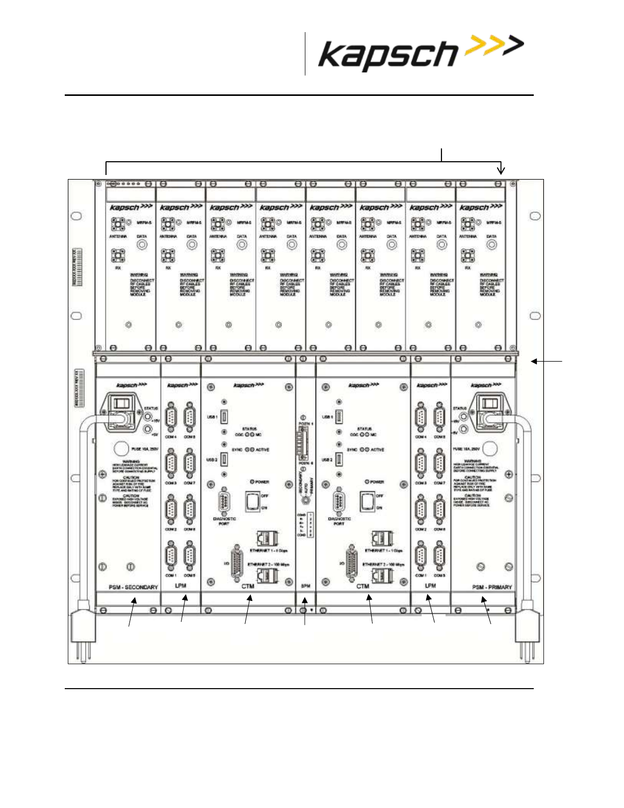
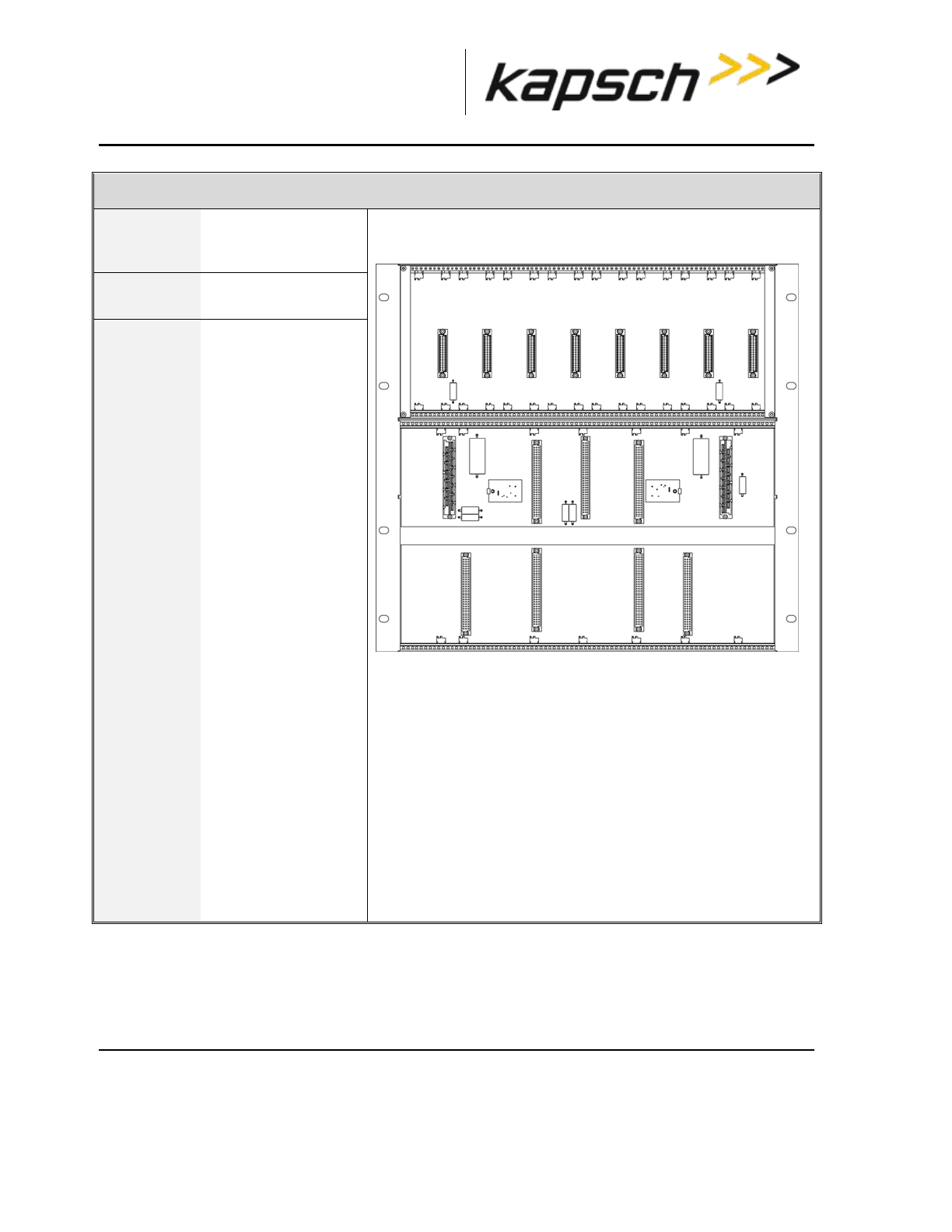
JANUS MPR system components
Figure 2-1: A Redundant Reader shows a rack equipped with eight Smart MRF modules (MRFM-S).
A Lane Kit consists of:
An antenna (see Figure 2-2)
An MRFM-S( in Figure 2-1: A Redundant Reader)
Two feedline adapter cable
One Circulator
One Circulator adapter cable. (3’5” for 902-904MHz, 3’3” for all other frequencies)

_
JANUS® Multi-Protocol Reader Ver. 2: Operating Instructions
Confidential UM 360463-202 Revision: A12 (Draft) Page 25 of 291
© Kapsch TrafficCom Canada Inc. 2014
These drawings and specifications contain confidential and proprietary information and are the property of Kapsch TrafficCom Canada Inc. and are issued in strict
confidence and will be kept confidential and used solely for the purpose intended and for no other purpose and shall not be transmitted, reproduced, copied, and/or
used as the basis for manufacture or sale of apparatus unless otherwise agreed to in writing by Kapsch TrafficCom Canada Inc.
FILE: MPR2_OPERATIONS_AND_MAINTENANCE-MANUAL_REV A12.DOCX 05/08/2014 11:24
Kapsch TrafficCom
The Reader consists of:
Note: Numbers in the list below refer to those associated with Figure 2-1: A Redundant Reader. The
DSM, and CFM are not shown in the figure.
One rack and Distribution Module
Two Controller Modules (CTM), each equipped with one Main Controller (MC),
one Channel Group Controller (CGC)
Two Configuration Modules (CFMs) attach directly to the DSM
One Synchronization Port Module (SPM)
Two Lane Port Modules (LPM)
One secondary Power Supply Module (PSM) and AC power cord
One primary Power Supply Module (PSM) and AC Power Cord
AC Power cords for the PSM’s
Note: Non-redundant Readers contain one CTM, one CFM, one LPM, and one PSM. For an illustration
of a non-redundant reader, see Appendix B.
Additional installation components required are:
Two RF cables from Reader to Circulator (type N male to type N female)
Sealing tapes for RF and DC connectors exposed to weather
Lightning arrestors
Optional Ethernet switch modules (ESMs)
Sync and inter-reader Ethernet cabling (if required)
Ethernet cables if ESMs used
300 CFM fan tray for operation above 55oC
Additional Site requirements are:
Cabinet with AC power, grounding, including reader ground bar,
Mounting structure for antenna
Ethernet or Serial cables to connect to the lane Controller(s)
_
JANUS® Multi-Protocol Reader Ver. 2: Operating Instructions
Confidential UM 360463-202 Revision: A12 (Draft) Page 26 of 291
© Kapsch TrafficCom Canada Inc. 2014
These drawings and specifications contain confidential and proprietary information and are the property of Kapsch TrafficCom Canada Inc. and are issued in strict
confidence and will be kept confidential and used solely for the purpose intended and for no other purpose and shall not be transmitted, reproduced, copied, and/or
used as the basis for manufacture or sale of apparatus unless otherwise agreed to in writing by Kapsch TrafficCom Canada Inc.
FILE: MPR2_OPERATIONS_AND_MAINTENANCE-MANUAL_REV A12.DOCX 05/08/2014 11:24
Kapsch TrafficCom
Figure 2-1: A Redundant Reader
_
JANUS® Multi-Protocol Reader Ver. 2: Operating Instructions
Confidential UM 360463-202 Revision: A12 (Draft) Page 27 of 291
© Kapsch TrafficCom Canada Inc. 2014
These drawings and specifications contain confidential and proprietary information and are the property of Kapsch TrafficCom Canada Inc. and are issued in strict
confidence and will be kept confidential and used solely for the purpose intended and for no other purpose and shall not be transmitted, reproduced, copied, and/or
used as the basis for manufacture or sale of apparatus unless otherwise agreed to in writing by Kapsch TrafficCom Canada Inc.
FILE: MPR2_OPERATIONS_AND_MAINTENANCE-MANUAL_REV A12.DOCX 05/08/2014 11:24
Kapsch TrafficCom
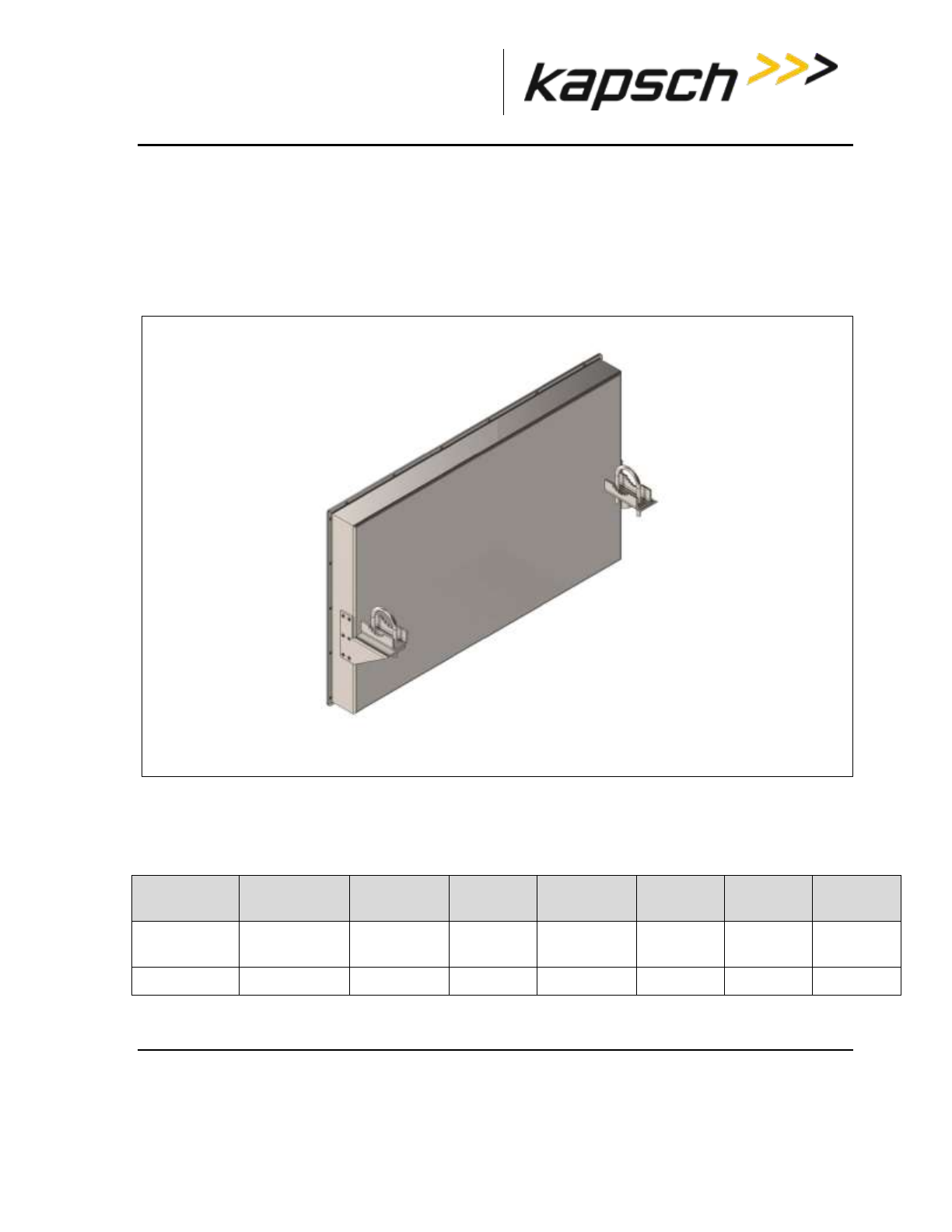
Antenna
The antenna sends and receives RF signals to and from the vehicle On Board Units (OBUs). The IAG
3 and IAG 1 antennas are recommended for the MPR2 reader. See Antenna Specifications, page 270
for more details. Figure 2-2 shows an illustration of the IAG 3 antenna, one of the recommended
antennas for the Multi-protocol Reader.
Figure 2-2: IAG 3 Antenna
IAG Antenna specifications
Table 2-1 IAG Antenna Specifications
P/N
Lane Kit #
Description
Width (in
inches)
Length (in
inches)
Depth (in
inches)
Weight1
(in lbs)
Mounting
800260-015
801692-019
3x4 dipole
array
34.5
21.25
3.13
19
horizontal
800260-011
3x3 Patch
34.5
31.75
2.3
28
horizontal
Note: Mounting information is provided as a guideline.

_
JANUS® Multi-Protocol Reader Ver. 2: Operating Instructions
Confidential UM 360463-202 Revision: A12 (Draft) Page 28 of 291
© Kapsch TrafficCom Canada Inc. 2014
These drawings and specifications contain confidential and proprietary information and are the property of Kapsch TrafficCom Canada Inc. and are issued in strict
confidence and will be kept confidential and used solely for the purpose intended and for no other purpose and shall not be transmitted, reproduced, copied, and/or
used as the basis for manufacture or sale of apparatus unless otherwise agreed to in writing by Kapsch TrafficCom Canada Inc.
FILE: MPR2_OPERATIONS_AND_MAINTENANCE-MANUAL_REV A12.DOCX 05/08/2014 11:24
Kapsch TrafficCom
Weight specified is applicable to the antenna structure only, that is, it does not include mounting
hardware.
_
JANUS® Multi-Protocol Reader Ver. 2: Operating Instructions
Confidential UM 360463-202 Revision: A12 (Draft) Page 29 of 291
© Kapsch TrafficCom Canada Inc. 2014
These drawings and specifications contain confidential and proprietary information and are the property of Kapsch TrafficCom Canada Inc. and are issued in strict
confidence and will be kept confidential and used solely for the purpose intended and for no other purpose and shall not be transmitted, reproduced, copied, and/or
used as the basis for manufacture or sale of apparatus unless otherwise agreed to in writing by Kapsch TrafficCom Canada Inc.
FILE: MPR2_OPERATIONS_AND_MAINTENANCE-MANUAL_REV A12.DOCX 05/08/2014 11:24
Kapsch TrafficCom
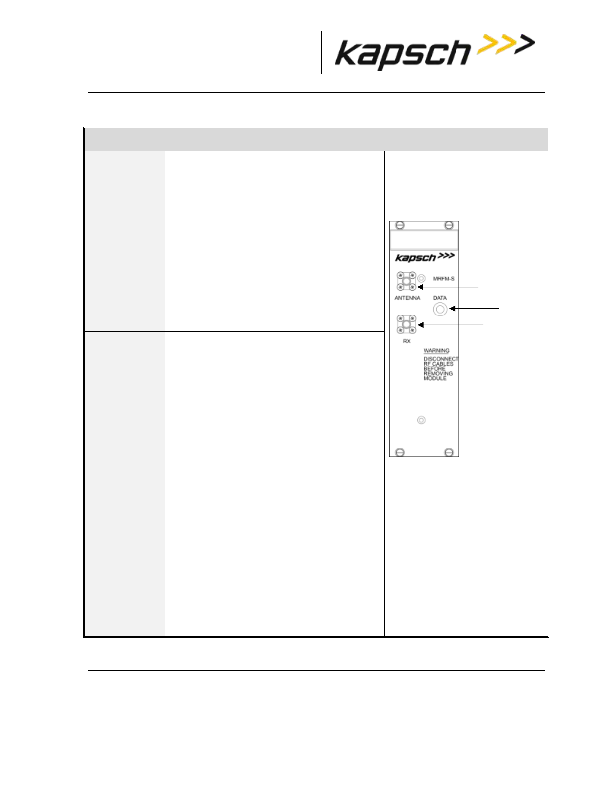
Module Descriptions
Smart Multi-protocol RF Module (MRFM-S)
Function
Converts digital data from the Reader to an
analog RF signal that is sent to the OBU via
the antenna.
Converts the analog RF signal collected from
the OBU via the antenna into a digital signal
that is sent to the CGC module via the DSM.
Units per
Redundant
Reader
One MRFM-S for each antenna. A maximum of
8 MRFM-S per Reader.
Redundant
No
Normal State
The DATA LED illuminates solid green
when RF data is being transmitted.
Connections
The MRFM-S module can support both bi-
static and mono-static output configurations.
In Mono-static operation only connection is
connected by an RF cable to the antenna.
In Bi-static output configurations, both
connections are connected by an RF
cable to the antenna.
_
JANUS® Multi-Protocol Reader Ver. 2: Operating Instructions
Confidential UM 360463-202 Revision: A12 (Draft) Page 30 of 291
© Kapsch TrafficCom Canada Inc. 2014
These drawings and specifications contain confidential and proprietary information and are the property of Kapsch TrafficCom Canada Inc. and are issued in strict
confidence and will be kept confidential and used solely for the purpose intended and for no other purpose and shall not be transmitted, reproduced, copied, and/or
used as the basis for manufacture or sale of apparatus unless otherwise agreed to in writing by Kapsch TrafficCom Canada Inc.
FILE: MPR2_OPERATIONS_AND_MAINTENANCE-MANUAL_REV A12.DOCX 05/08/2014 11:24
Kapsch TrafficCom
Distributions Module (DSM) and Rack
Function
The DSM is the back
plane of the Reader
rack.
Units per
Redundant
Reader
One DSM and one
Rack
Connections
The MRFM-S. PSM,
LPM, CTM, and SPM
modules slide into
the Rack and
connect to the DSM.
The CFMs attach
directly to the DSM.
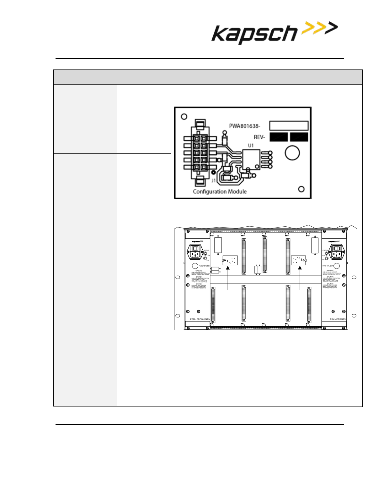
_
JANUS® Multi-Protocol Reader Ver. 2: Operating Instructions
Confidential UM 360463-202 Revision: A12 (Draft) Page 31 of 291
© Kapsch TrafficCom Canada Inc. 2014
These drawings and specifications contain confidential and proprietary information and are the property of Kapsch TrafficCom Canada Inc. and are issued in strict
confidence and will be kept confidential and used solely for the purpose intended and for no other purpose and shall not be transmitted, reproduced, copied, and/or
used as the basis for manufacture or sale of apparatus unless otherwise agreed to in writing by Kapsch TrafficCom Canada Inc.
FILE: MPR2_OPERATIONS_AND_MAINTENANCE-MANUAL_REV A12.DOCX 05/08/2014 11:24
Kapsch TrafficCom
Configuration Module (CFM)
Function
Stores the
Reader
configuration file
so that the
Reader
configuration is
retained when
the CTMs fail or
are removed.
Units per Redundant
Reader
One CFM on the
secondary side
,
One CFM on the
primary side
Connections
The CFMs
attach directly to
the DSM in the
secondary
location and
the primary
location .
CFMs should
not be swapped
between
readers or within
the reader.
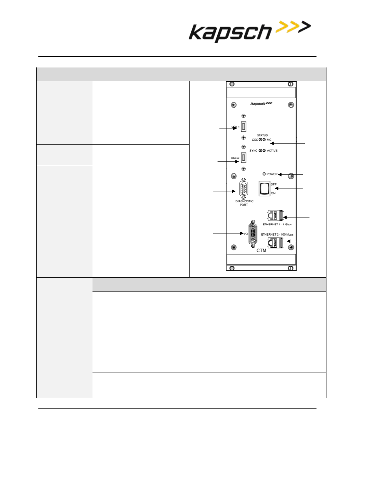
_
JANUS® Multi-Protocol Reader Ver. 2: Operating Instructions
Confidential UM 360463-202 Revision: A12 (Draft) Page 32 of 291
© Kapsch TrafficCom Canada Inc. 2014
These drawings and specifications contain confidential and proprietary information and are the property of Kapsch TrafficCom Canada Inc. and are issued in strict
confidence and will be kept confidential and used solely for the purpose intended and for no other purpose and shall not be transmitted, reproduced, copied, and/or
used as the basis for manufacture or sale of apparatus unless otherwise agreed to in writing by Kapsch TrafficCom Canada Inc.
FILE: MPR2_OPERATIONS_AND_MAINTENANCE-MANUAL_REV A12.DOCX 05/08/2014 11:24
Kapsch TrafficCom
Control Module (CTM)
Function
Contains the Reader processor
(MC), the Channel Group
Controller module (CGC).
Allows the CTM to be reset with
the CTM ON/OFF switch .
Controls when the RF modules
are interrogated.
X
Units per Redundant
Reader
One CTM on primary side,
One CTM on secondary side
Normal State
The POWER LED illuminates
green when the CTM is on and is
receiving power from the PSM.
The STATUS LEDs illuminate
green to indicate SYNC is
functional, CTM is active, CGC is
functional and MC is functional.
Connections
Port
Function
ETHERNET 1 - 1 Gbps
One option for connecting a service laptop directly
to the Reader,. or, for creating a network to connect
the Readers and LCs together.
ETHERNET 2 – 100 Mbps
For connecting several Readers together to create
an Inter-Reader (IR) network, or for connecting a
service laptop when Ethernet 1 is connected to the
Lane Controller.
DIAGNOSTIC PORT
A second option for connecting a service laptop
directly to the Reader. The browser interface cannot
be accessed from this port.
I/O
Reserved for future use.

_
JANUS® Multi-Protocol Reader Ver. 2: Operating Instructions
Confidential UM 360463-202 Revision: A12 (Draft) Page 33 of 291
© Kapsch TrafficCom Canada Inc. 2014
These drawings and specifications contain confidential and proprietary information and are the property of Kapsch TrafficCom Canada Inc. and are issued in strict
confidence and will be kept confidential and used solely for the purpose intended and for no other purpose and shall not be transmitted, reproduced, copied, and/or
used as the basis for manufacture or sale of apparatus unless otherwise agreed to in writing by Kapsch TrafficCom Canada Inc.
FILE: MPR2_OPERATIONS_AND_MAINTENANCE-MANUAL_REV A12.DOCX 05/08/2014 11:24
Kapsch TrafficCom
Control Module (CTM)
Port
Function
USB 1
USB 2
A third option for connecting a service laptop, via an
Ethernet adapter, directly to the Reader, or for
saving the Reader configuration to a flash drive, Or
for automatically or manually copying the Reader
log files to a flash drive.
CTM MC
The MC is a single-board computer that runs the Reader firmware. The MC is mounted in the CTM.
CTM CGC2
The CGC2 handles the communications between the MC and the RF modules. It also handles the
serial communications between the reader and the Lane Controller via the serial connections on the
LPM. The CGC2 is mounted in the CTM.
The CGC2 hardware supports the following functions.
• Controls the protocol frame timing for each protocol
• Controls the RF channel scanning as per configuration
• Handles the data communication exchange with the transponder via the RF link
• Handles inter-reader frame synchronization
• Provides hardware interface for redundancy operation
• Provides hardware interface for supporting up to eight (8) MRFM-S
• Provides in-system program capability via the Master interface, for firmware and hardware
configuration where applicable
• Provides connections for eight Lane Controller Ports
• Provides pass-through provisional connections for the Host Port .
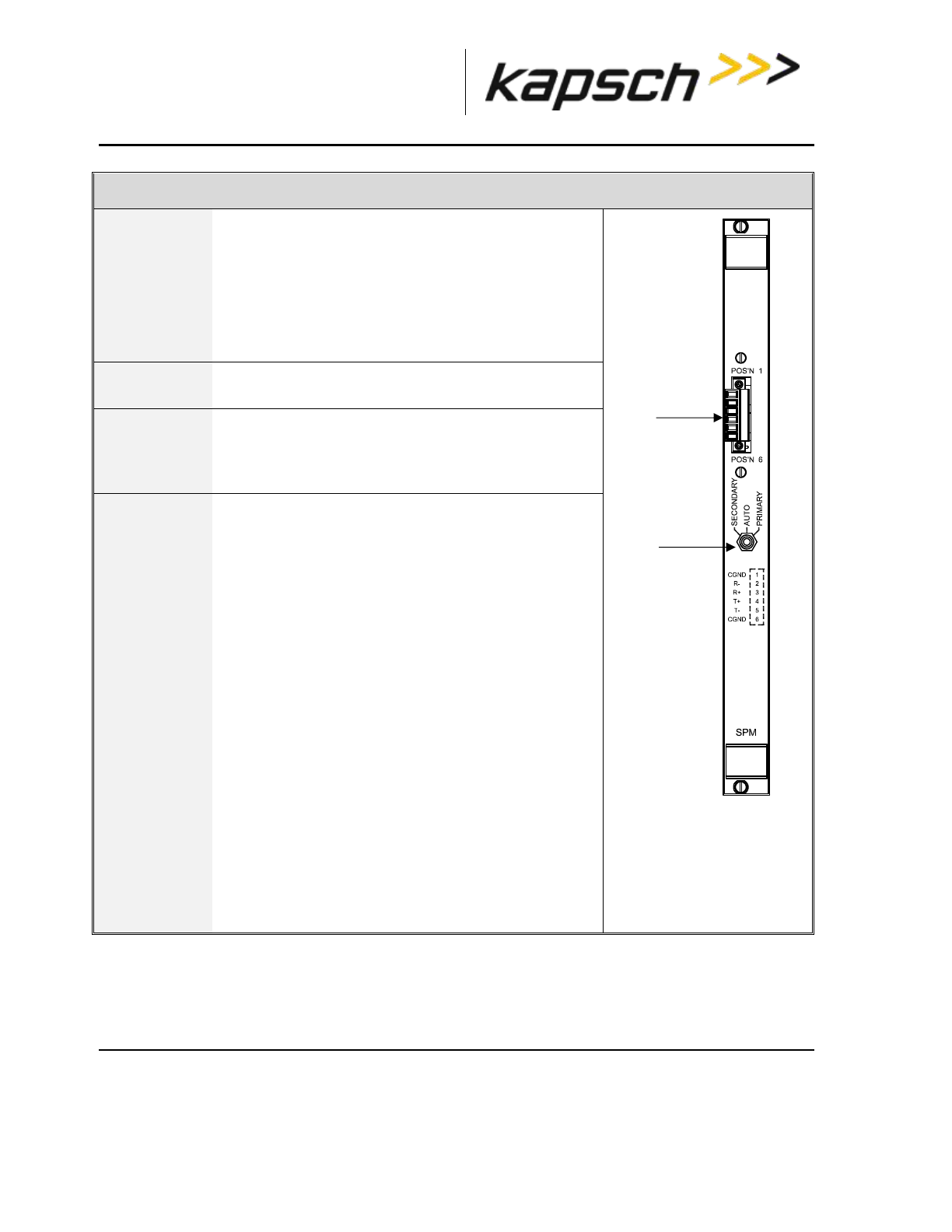
_
JANUS® Multi-Protocol Reader Ver. 2: Operating Instructions
Confidential UM 360463-202 Revision: A12 (Draft) Page 34 of 291
© Kapsch TrafficCom Canada Inc. 2014
These drawings and specifications contain confidential and proprietary information and are the property of Kapsch TrafficCom Canada Inc. and are issued in strict
confidence and will be kept confidential and used solely for the purpose intended and for no other purpose and shall not be transmitted, reproduced, copied, and/or
used as the basis for manufacture or sale of apparatus unless otherwise agreed to in writing by Kapsch TrafficCom Canada Inc.
FILE: MPR2_OPERATIONS_AND_MAINTENANCE-MANUAL_REV A12.DOCX 05/08/2014 11:24
Kapsch TrafficCom
Synchronization Port Module (SPM)
Function
Sends out the status of the Reader (ready or busy) to
the other Readers in the synchronization network.
Signals to the CTM when all other Readers in the
synchronization network are ready.
Allows the switchover mode to be set to
SECONDARY—AUTO—PRIMARY by the
Redundancy Mode switch on the SPM.
Units per
Redundant
Reader
One
Normal State
N/A (no status indicators on module)
Connections
The SPM terminal block is connected to the other
Readers in the synchronization network via the sync
terminal block hub.
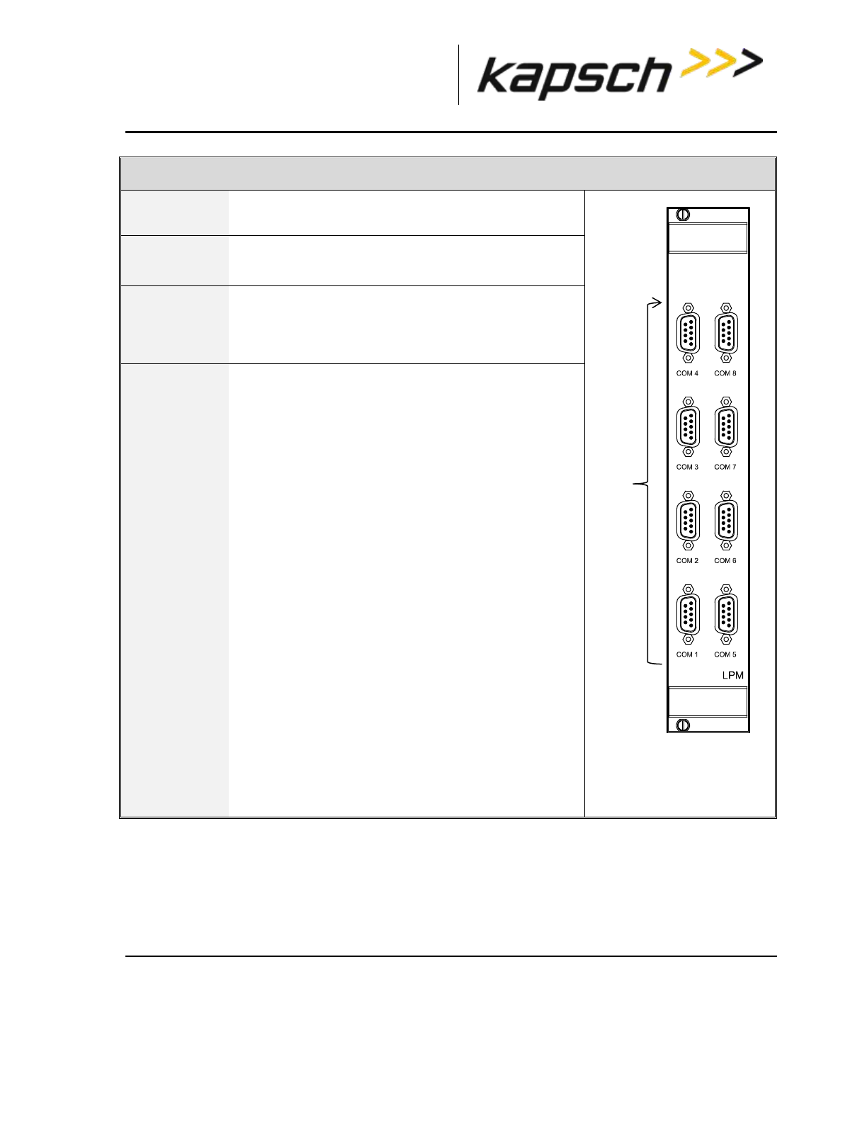
_
JANUS® Multi-Protocol Reader Ver. 2: Operating Instructions
Confidential UM 360463-202 Revision: A12 (Draft) Page 35 of 291
© Kapsch TrafficCom Canada Inc. 2014
These drawings and specifications contain confidential and proprietary information and are the property of Kapsch TrafficCom Canada Inc. and are issued in strict
confidence and will be kept confidential and used solely for the purpose intended and for no other purpose and shall not be transmitted, reproduced, copied, and/or
used as the basis for manufacture or sale of apparatus unless otherwise agreed to in writing by Kapsch TrafficCom Canada Inc.
FILE: MPR2_OPERATIONS_AND_MAINTENANCE-MANUAL_REV A12.DOCX 05/08/2014 11:24
Kapsch TrafficCom
Lane Port Module (LPM)
Function
Provides a serial interface between the LCs and
CTM. All OBU Data processing is done by the CTM.
Units per
Redundant
Reader
One LPM on primary side,
One LPM on secondary side
Normal State
N/A (no status indicators on module)
Connections
The Reader can send real-time OBU transactions to
the LCs via the eight serial ports on the LPM. The
LC can also update the Reader configuration via
these ports.
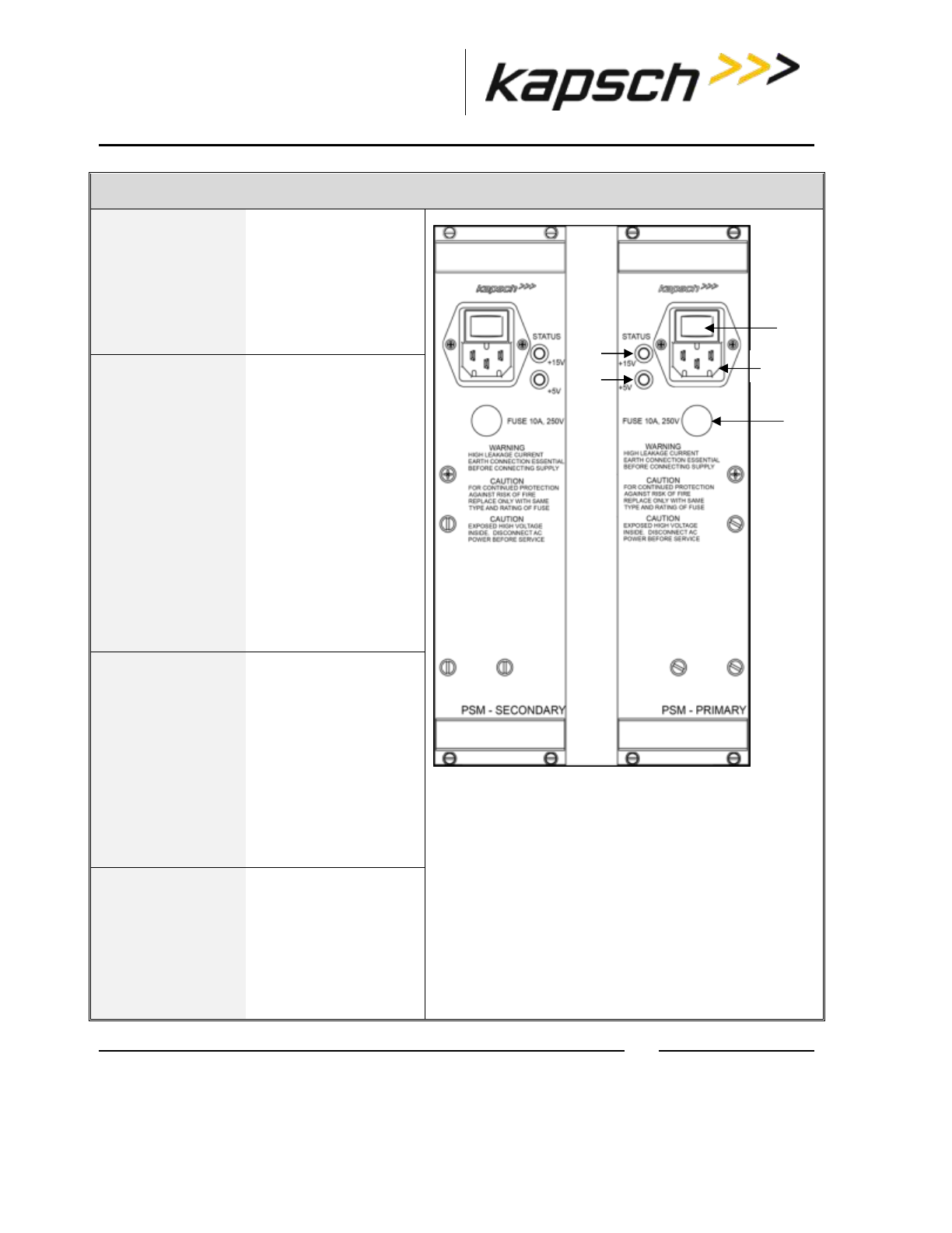
_
JANUS® Multi-Protocol Reader Ver. 2: Operating Instructions
Confidential UM 360463-202 Revision: A12 (Draft) Page 36 of 291
© Kapsch TrafficCom Canada Inc. 2014
These drawings and specifications contain confidential and proprietary information and are the property of Kapsch TrafficCom Canada Inc. and are issued in strict
confidence and will be kept confidential and used solely for the purpose intended and for no other purpose and shall not be transmitted, reproduced, copied, and/or
used as the basis for manufacture or sale of apparatus unless otherwise agreed to in writing by Kapsch TrafficCom Canada Inc.
FILE: MPR2_OPERATIONS_AND_MAINTENANCE-MANUAL_REV A12.DOCX 05/08/2014 11:24
Kapsch TrafficCom
Power Supply Module (PSM)
Function
Provides DC power to
the modules in the
Reader rack.
Allows each side (primary
or secondary) to be
powered on and off via a
power switch .
Units per Redundant
Reader
One secondary PSM
on the secondary side
One primary PSM on
the primary side
The secondary and
primary PSMs are not
interchangeable since
they are mirror images
of each other. The
secondary PSM is
keyed to insert in the
leftmost rack slot and
the primary PSM is
keyed to insert in the
rightmost rack slot.
Normal State
A +15V STATUS LED
illuminates green to
indicate that 15V DC is
being supplied to the
Reader.
A +5V STATUS LED
illuminates green to
indicate that 5V DC is
being supplied to the
Reader.
Connections
A power cable plugs
into a socket to
supply 120VAC to the
PSMs. Each PSM is
equipped with a
replaceable 10A fuse
.
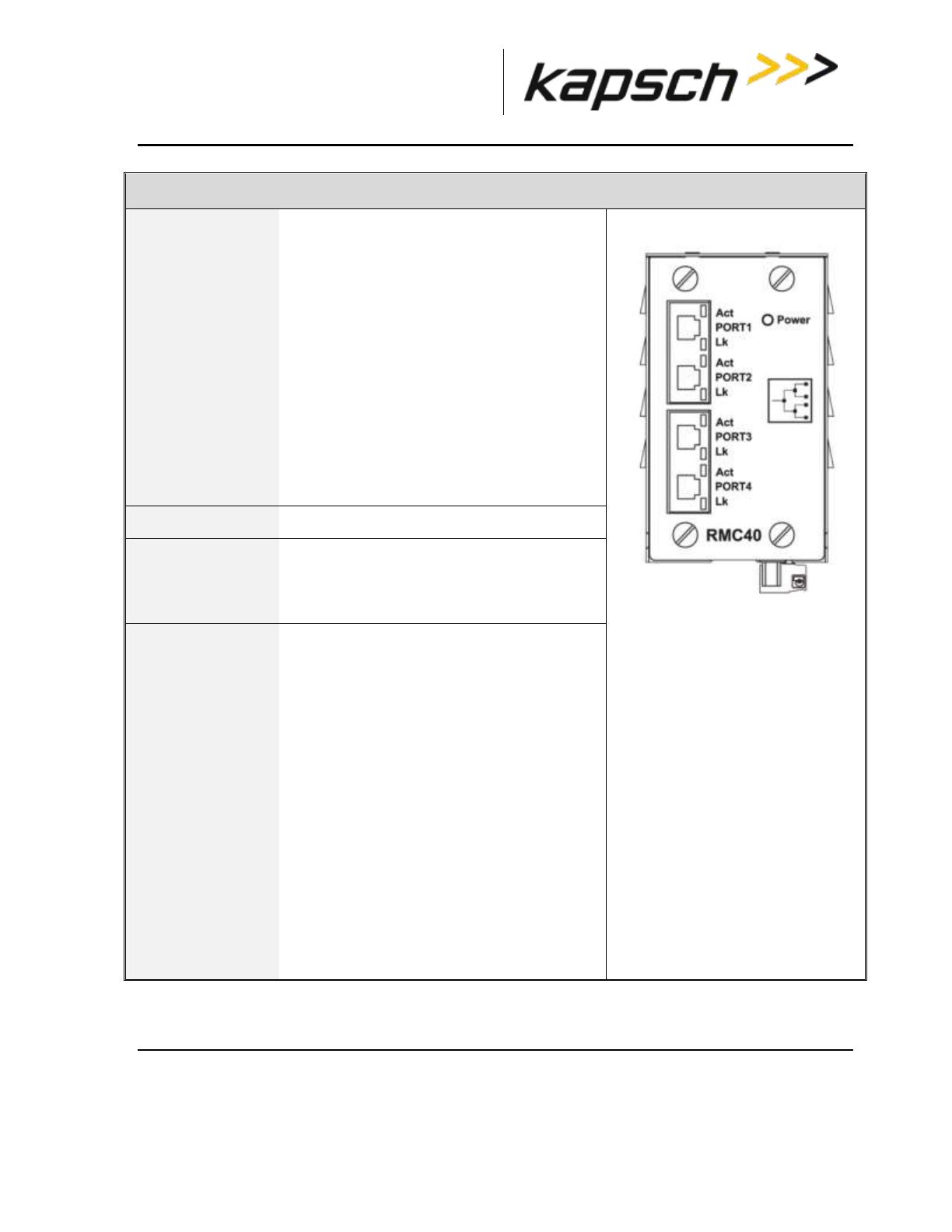
_
JANUS® Multi-Protocol Reader Ver. 2: Operating Instructions
Confidential UM 360463-202 Revision: A12 (Draft) Page 37 of 291
© Kapsch TrafficCom Canada Inc. 2014
These drawings and specifications contain confidential and proprietary information and are the property of Kapsch TrafficCom Canada Inc. and are issued in strict
confidence and will be kept confidential and used solely for the purpose intended and for no other purpose and shall not be transmitted, reproduced, copied, and/or
used as the basis for manufacture or sale of apparatus unless otherwise agreed to in writing by Kapsch TrafficCom Canada Inc.
FILE: MPR2_OPERATIONS_AND_MAINTENANCE-MANUAL_REV A12.DOCX 05/08/2014 11:24
Kapsch TrafficCom
Ethernet Switch Module (ESM)
Function
Can connect an IR network with up to three
Readers for Open Road Tolling (ORT)
applications via the Ethernet 2 port on the
CTMs. The IR network is used to improve
the accuracy of the voting that determines
the lane assignment between Readers
covering adjacent lanes.
Can connect an LC network with all Readers
to a Lane Controller and host computer via
the Ethernet 1 port on the CTMs. The host
computer can be used to access the browser
interface for each Reader CTM in the
network.
The Ethernet switch Module, if used, shall be
mounted in a reader cabinet.
Units per Redundant
Reader
Two per Ethernet network
Normal State
See the manufacturer’s documentation for
details.
Connections
See the manufacturer’s documentation for
details.
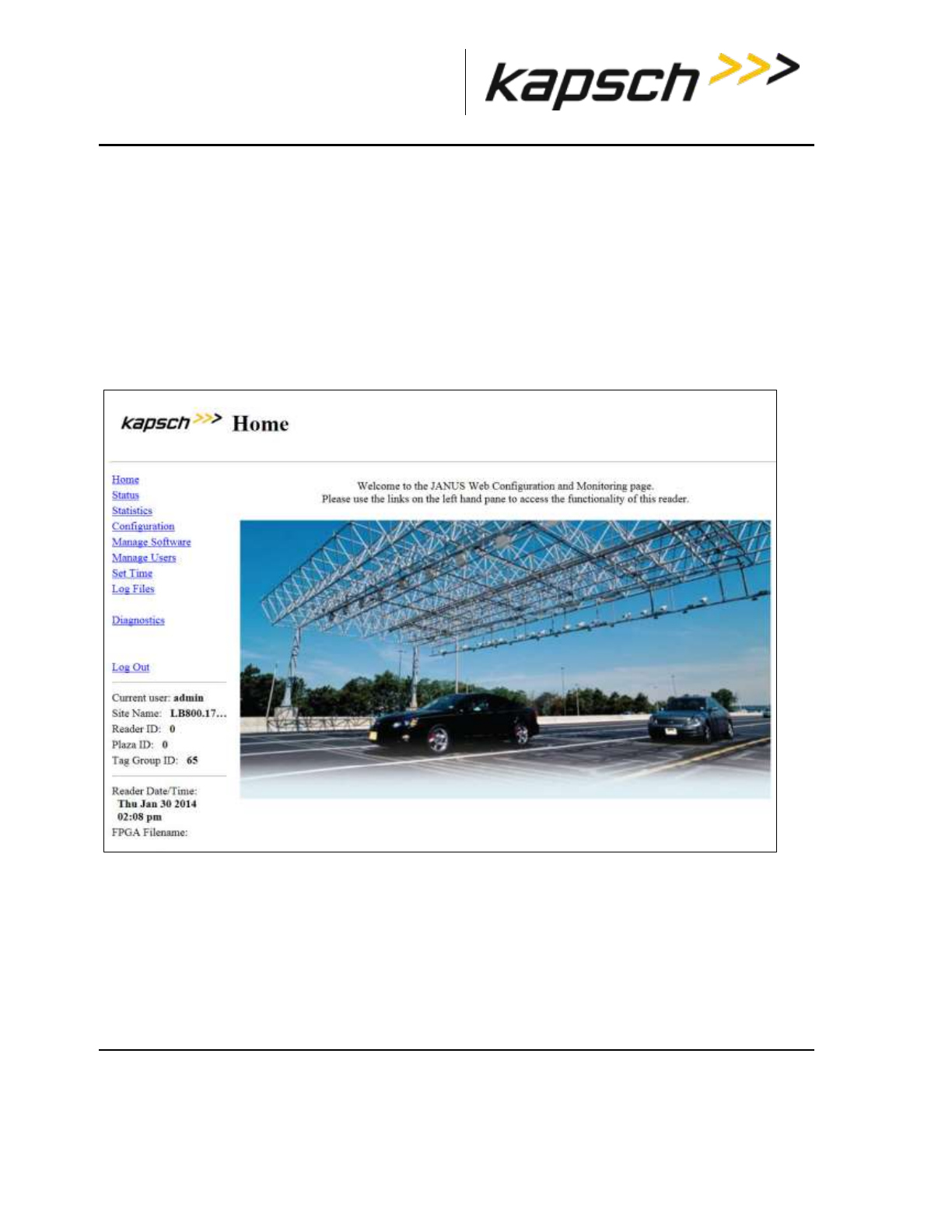
_
JANUS® Multi-Protocol Reader Ver. 2: Operating Instructions
Confidential UM 360463-202 Revision: A12 (Draft) Page 38 of 291
© Kapsch TrafficCom Canada Inc. 2014
These drawings and specifications contain confidential and proprietary information and are the property of Kapsch TrafficCom Canada Inc. and are issued in strict
confidence and will be kept confidential and used solely for the purpose intended and for no other purpose and shall not be transmitted, reproduced, copied, and/or
used as the basis for manufacture or sale of apparatus unless otherwise agreed to in writing by Kapsch TrafficCom Canada Inc.
FILE: MPR2_OPERATIONS_AND_MAINTENANCE-MANUAL_REV A12.DOCX 05/08/2014 11:24
Kapsch TrafficCom
The CTM web interface
You can use a service laptop equipped with a web browser such as Internet Explorer, Firefox, or
Chrome to access the CTM web interface, shown below. After entering your user name and password,
you can monitor and configure the Reader depending on the permissions assigned to your user
account.
Note: Depending on the permissions given a user by the Administrator, the panel on the left (indicated
by the rectangle in the figure below) can have different options. For instance, the view below is for an
Administrator. Among other priviledges, an administrator can create, delete or modify users using the
Manage Users option.
Each CTM has its own browser interface. Changing configuration settings while connected to the
primary CTM, for example, does not change the configuration settings for the secondary CTM.
Note: Any changes applied to one CTM in a redundant Reader must then be applied to the other CTM,
as required.
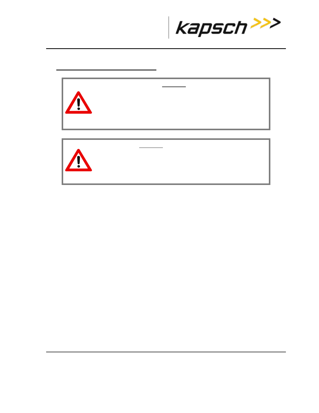
_
JANUS® Multi-Protocol Reader Ver. 2: Operating Instructions
Confidential UM 360463-202 Revision: A12 (Draft) Page 39 of 291
© Kapsch TrafficCom Canada Inc. 2014
These drawings and specifications contain confidential and proprietary information and are the property of Kapsch TrafficCom Canada Inc. and are issued in strict
confidence and will be kept confidential and used solely for the purpose intended and for no other purpose and shall not be transmitted, reproduced, copied, and/or
used as the basis for manufacture or sale of apparatus unless otherwise agreed to in writing by Kapsch TrafficCom Canada Inc.
FILE: MPR2_OPERATIONS_AND_MAINTENANCE-MANUAL_REV A12.DOCX 05/08/2014 11:24
Kapsch TrafficCom
3. OPERATING PROCEDURES
CAUTION:
Improper modification of configuration parameters may adversely
affect system operation. The default values may not be appropriate for
the specific application. It is the system integrator’s responsibility to
tailor the configuration parameters to the specific operating
environment, with the aid of Kapsch’s Operations Group.
CAUTION: Redundant Reader
Both CTMs in a redundant Reader must be properly configured. Each
CTM has its own browser interface and is configured independently.
Ensure any configuration changes made to one CTM are applied to the
other CTM, as required.
Starting up the Reader
This procedure outlines the correct way to power on and boot up a Reader.
Prerequisites: PSM power switches set to the off (0) position.
1. CTM ON/OFF switches set to OFF.
2. Set the Redundancy Mode switch on the SPM to AUTO.
3. Set the secondary and primary PSM power switches to the on (I) position.
Result: The +15V STATUS LED and the +5 STATUS LED on the PSMs illuminate solid green.
4. Set the CTM ON/OFF switch to the ON position, and wait for the CTM to complete its power up cycle
(approximately 120 Seconds).
Result: The POWER LED illuminates green. The STATUS LEDs illuminate green to indicate SYNC is
functional, CTM is active, CGC is functional and MC is functional.
Note: If any CTM STATUS LEDs indicate an abnormal state, (see Table 6-1: CTM LED states explained
on page 192) perform the necessary troubleshooting procedure. See Troubleshooting Methodology on
page 190 for more information.
Shutting down the Reader
This procedure outlines the correct way to power down a Reader.
Prerequisites: None.

_
JANUS® Multi-Protocol Reader Ver. 2: Operating Instructions
Confidential UM 360463-202 Revision: A12 (Draft) Page 40 of 291
© Kapsch TrafficCom Canada Inc. 2014
These drawings and specifications contain confidential and proprietary information and are the property of Kapsch TrafficCom Canada Inc. and are issued in strict
confidence and will be kept confidential and used solely for the purpose intended and for no other purpose and shall not be transmitted, reproduced, copied, and/or
used as the basis for manufacture or sale of apparatus unless otherwise agreed to in writing by Kapsch TrafficCom Canada Inc.
FILE: MPR2_OPERATIONS_AND_MAINTENANCE-MANUAL_REV A12.DOCX 05/08/2014 11:24
Kapsch TrafficCom
1. Set both CTM ON/OFF switches to OFF.
2. Set both PSM power switches to the off (0) position.
Manually switching a Reader to the redundant side
The Reader is manually switched between the primary and secondary sides. This is necessary, for
example, when recovering a Reader back to the Primary side when automatic recovery is not enabled.
Prerequisites: Ensure no faults exist on the side being activated.
1. Set the SPM redundancy mode switch to either SECONDARY or PRIMARY, as applicable.
Result: The ACTIVE LED on the CTM of the selected side illuminates green, indicating the selected side
is active.
Note: If the redundancy mode switch is set to PRIMARY, the Reader stays in Primary mode and does not
switch operation to the secondary side unless the primary side fails.
Note: If the switch is set to SECONDARY, the Reader stays in Secondary mode and does not switch
operation to the primary side unless the secondary side fails or the primary side recovers.
Connecting a service laptop to the Reader
You can use a service laptop to access the CTM web interface interface by connecting directly to one
of the CTM USB ports or the ETHERNET 1 port.
Changing the service laptop IP address
1. In Windows, go to Start Settings Control Panel Network Connections Local Area Connection
Properties Internet Protocol (TCP/IP) Properties.
2. Select Use the following IP address, then enter the IP address using the Reader network number in the
first three fields (ex. 192.168.1._ ) followed by a unique host number in the fourth field.
3. Enter 225.225.225.0 in the subnet mask and leave the default gateway blank.
Testing the connection to the reader
1. In Windows, go to Start Run.
2. Type ‘ping’, followed by the ETHERNET 1 port IP address or the USB adapter address, depending on
what the laptop is connected.
3. Click OK.
Result: Several replies from the Reader IP address display momentarily in a DOS window. You are
ready to access the CTM web interface (see Accessing the CTM web interface page 41).
Note: If a reply is not received during the test, check the cable, connections, and IP addresses, then
repeat step 1.

_
JANUS® Multi-Protocol Reader Ver. 2: Operating Instructions
Confidential UM 360463-202 Revision: A12 (Draft) Page 41 of 291
© Kapsch TrafficCom Canada Inc. 2014
These drawings and specifications contain confidential and proprietary information and are the property of Kapsch TrafficCom Canada Inc. and are issued in strict
confidence and will be kept confidential and used solely for the purpose intended and for no other purpose and shall not be transmitted, reproduced, copied, and/or
used as the basis for manufacture or sale of apparatus unless otherwise agreed to in writing by Kapsch TrafficCom Canada Inc.
FILE: MPR2_OPERATIONS_AND_MAINTENANCE-MANUAL_REV A12.DOCX 05/08/2014 11:24
Kapsch TrafficCom
Accessing the CTM web interface
The CTM web interface interface monitors and configures the CTM.
Note: When you select an item through choosing a checkbox, or type into a field, pressing Enter or
selecting another tab will accept your selection.
Prerequisites: A service laptop connected to one of the CTM USB ports or the ETHERNET 1 port of
the Reader.
1. Launch the web browser on the computer.
Note: You can use a recent versions of either Internet Explorer, Firefox or Chrome for a browser.
ATTENTION: When using certain versions of Internet Explorer, you may experience
missing strings of text when a CTM screen displays. Press control and F5 (Ctrl F5)
simultaneously. This action clears the buffer and refreshes the screen.
Note: The default IP address of the primary and secondary CTM ETHERNET 1 port is 192.168.1.50. The
IP address may change during installation.
2. Consult the record of system IP addresses maintained by the system integrator to determine the correct
IP address by using the hypertrm command. See Using HyperTerminal to connect to the DIAGNOSTIC
PORT on page 260.
Note: The default IP addresses of the primary and secondary CTM ETHERNET 2 port are 192.168.0.50
and 192.168.0.51 respectively. The IP addresses may change during installation.
3. Consult the record of system IP addresses to determine the correct IP address by using the hypertrm
command. See Using HyperTerminal to connect to the DIAGNOSTIC PORT on page 260.
4. In the address bar of the web browser, type: https:// followed by the IP address of the ETHERNET 1 Port
or USB Adapter.
5. Use the following decision table to continue the procedure.
IF …
THEN …
you click the Login button and a dialog box requesting
a username and password appears,
go to step 6.
a 403 Forbidden error message appears,
ensure the IP address entered in the address bar is
correct and that the IP address is preceded by https://
a web browser message indicating there is a
connection problem appears,
confirm that the IP address entered in step 2 is the
correct record of system IP addresses.
a security certificate warning (Internet Explorer (IE)) or
untrusted connection warning (Firefox) appears,
for IE, go to the website;
for Firefox, add an exception.
Note: Usernames and passwords are case-sensitive.
6. Enter your username and password.
Result: The following Home page appears.
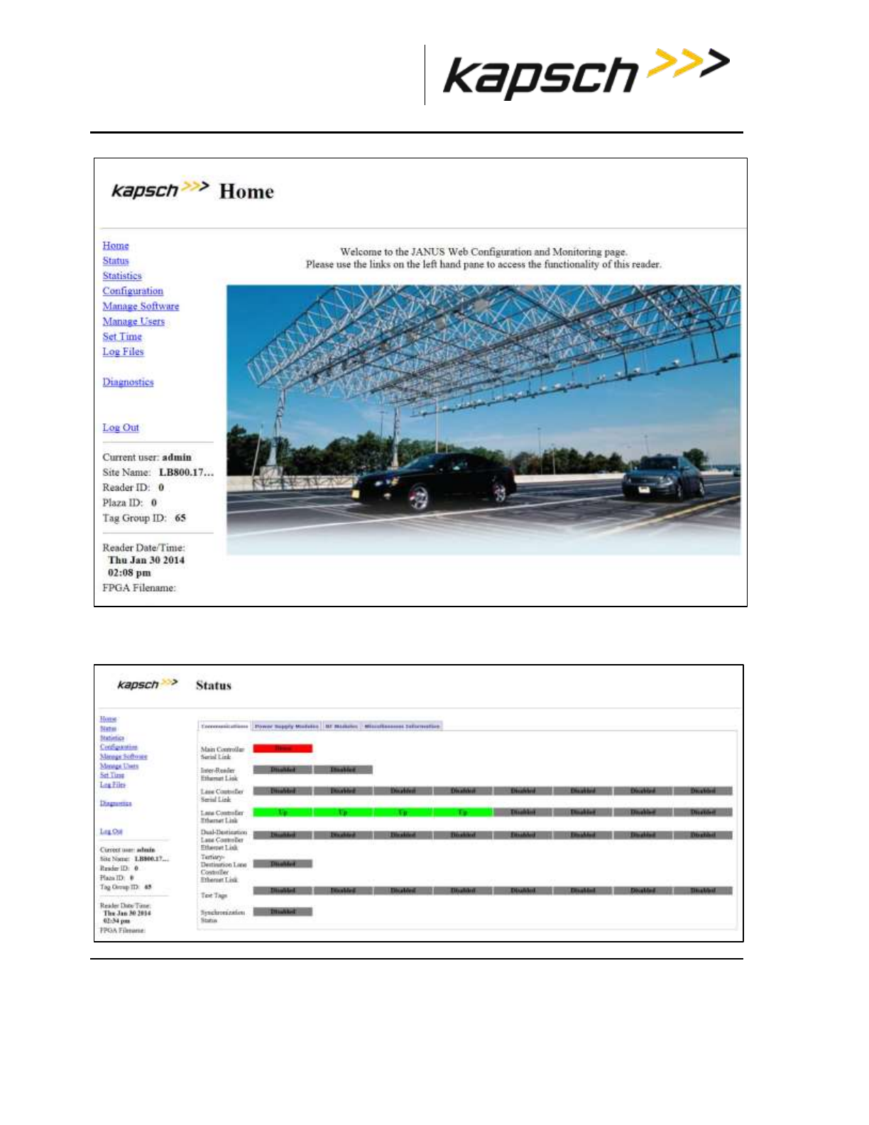
_
JANUS® Multi-Protocol Reader Ver. 2: Operating Instructions
Confidential UM 360463-202 Revision: A12 (Draft) Page 42 of 291
© Kapsch TrafficCom Canada Inc. 2014
These drawings and specifications contain confidential and proprietary information and are the property of Kapsch TrafficCom Canada Inc. and are issued in strict
confidence and will be kept confidential and used solely for the purpose intended and for no other purpose and shall not be transmitted, reproduced, copied, and/or
used as the basis for manufacture or sale of apparatus unless otherwise agreed to in writing by Kapsch TrafficCom Canada Inc.
FILE: MPR2_OPERATIONS_AND_MAINTENANCE-MANUAL_REV A12.DOCX 05/08/2014 11:24
Kapsch TrafficCom
7. Click the Status link located on the left panel.
Result: The following Status page appears.
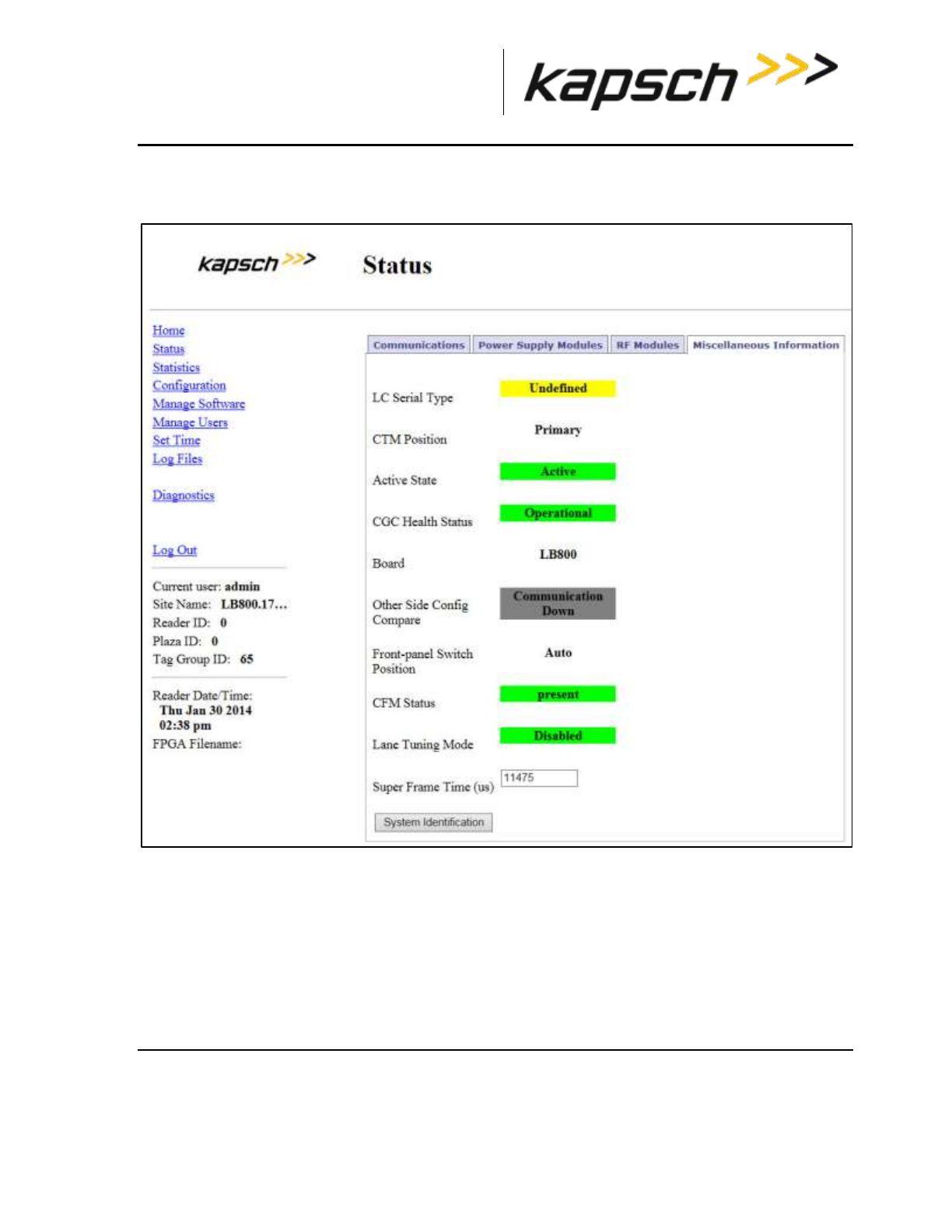
_
JANUS® Multi-Protocol Reader Ver. 2: Operating Instructions
Confidential UM 360463-202 Revision: A12 (Draft) Page 43 of 291
© Kapsch TrafficCom Canada Inc. 2014
These drawings and specifications contain confidential and proprietary information and are the property of Kapsch TrafficCom Canada Inc. and are issued in strict
confidence and will be kept confidential and used solely for the purpose intended and for no other purpose and shall not be transmitted, reproduced, copied, and/or
used as the basis for manufacture or sale of apparatus unless otherwise agreed to in writing by Kapsch TrafficCom Canada Inc.
FILE: MPR2_OPERATIONS_AND_MAINTENANCE-MANUAL_REV A12.DOCX 05/08/2014 11:24
Kapsch TrafficCom
8. Select the Miscellaneous Information tab.
Result: The following screen appears.
9. Click the System Identification button to confirm which Reader CTM web interface you are viewing, and
that the computer is communicating successfully.
Result: The MC LED of the CTM flashes: green – red – amber – green three times to indicate
communication.

_
JANUS® Multi-Protocol Reader Ver. 2: Operating Instructions
Confidential UM 360463-202 Revision: A12 (Draft) Page 44 of 291
© Kapsch TrafficCom Canada Inc. 2014
These drawings and specifications contain confidential and proprietary information and are the property of Kapsch TrafficCom Canada Inc. and are issued in strict
confidence and will be kept confidential and used solely for the purpose intended and for no other purpose and shall not be transmitted, reproduced, copied, and/or
used as the basis for manufacture or sale of apparatus unless otherwise agreed to in writing by Kapsch TrafficCom Canada Inc.
FILE: MPR2_OPERATIONS_AND_MAINTENANCE-MANUAL_REV A12.DOCX 05/08/2014 11:24
Kapsch TrafficCom
Logging out of the CTM web interface
Logging out of the CTM web interface terminates the connection between the service laptop and the
CTM web interface.
Prerequisites: Connect the service laptop to the Reader configuration port to access the CTM web
interface. Refer to Connecting a service laptop to the Reader, page 40.
1. Click Log Out from the navigation side bar.
Result: You are immediately logged out from the CTM web interface.
Changing your password
Any user can change their own password, although the procedure is different for users with User
Admin permissions. This procedure outlines how to change a password for users with User Admin
permissions and for those without.
Prerequisites: Connect the service laptop to the Reader configuration port to access the CTM web
interface. Refer to Connecting a service laptop to the Reader, page 40.
1. Login to the user account that requires a password change.
2. Use the following decision table to continue the procedure.
IF you logged into an account that …
THEN …
has User Admin permissions,
navigate to the Change Password tab on the User
Management page. Go to step 3.
does NOT have User Admin permissions,
from ANY page, click Change Password in the
navigation sidebar.
Result: The User Management Change Password page
appears. Go to step 3.
3. Enter your new password in the New Password and Confirm New Password fields.
4. Click the Submit button.
Result: Your password is now changed
5. If, after you have changed your password, an authentication window appears, enter your user name and
new password to return to the browser interface.
Resetting a forgotten password
If a user forgets their password, the password can be cleared by another user with User Admin
permissions. The Reader accepts any password from the user until the password is changed. This
procedure requires two users; a user with User Admin permissions and the user requiring a reset
password.

_
JANUS® Multi-Protocol Reader Ver. 2: Operating Instructions
Confidential UM 360463-202 Revision: A12 (Draft) Page 45 of 291
© Kapsch TrafficCom Canada Inc. 2014
These drawings and specifications contain confidential and proprietary information and are the property of Kapsch TrafficCom Canada Inc. and are issued in strict
confidence and will be kept confidential and used solely for the purpose intended and for no other purpose and shall not be transmitted, reproduced, copied, and/or
used as the basis for manufacture or sale of apparatus unless otherwise agreed to in writing by Kapsch TrafficCom Canada Inc.
FILE: MPR2_OPERATIONS_AND_MAINTENANCE-MANUAL_REV A12.DOCX 05/08/2014 11:24
Kapsch TrafficCom
Prerequisites: The user clearing the password must have User Admin permissions.
Note: The User Administrator should ensure that the user sets a new password after the password is
cleared. Otherwise, the Reader will continue to accept any password for that user account.
1. Navigate to the User Management tab on the User Management page.
2. Use the following decision table to continue the procedure.
IF you logged into an account that …
THEN …
has User Admin permissions,
go to step 3 and continue to step 5.
does NOT have User Admin permissions,
go to step 6 and continue to step 8.
3. Click the corresponding Clear Password button of the user whose password needs resetting.
4. Click Yes to confirm.
5. Log out (see Logging out of the CTM web interface, page 44).
6. Select Change Password from the navigation sidebar.
7. Enter your user name and compose a password.
Note: This password does not become your new password.
8. Change your password (see Changing your password on page 44).
Result: Your password resets.
Configuring the Reader to recover automatically to the primary side
The Reader can be configured to automatically activate the primary side once a failure causing a
switchover to the secondary side has cleared.
Prerequisites: Connect the service laptop to the Reader configuration port to access the CTM web
interface. Refer to Connecting a service laptop to the Reader, page 40.
Note: You must have Advanced User permissions.
1. Set the SPM redundancy mode switch to the AUTO position.
2. From the CTM web Main Page, select the Configuration link on the left panel of the screen.
Result: The following Configuration page appears.
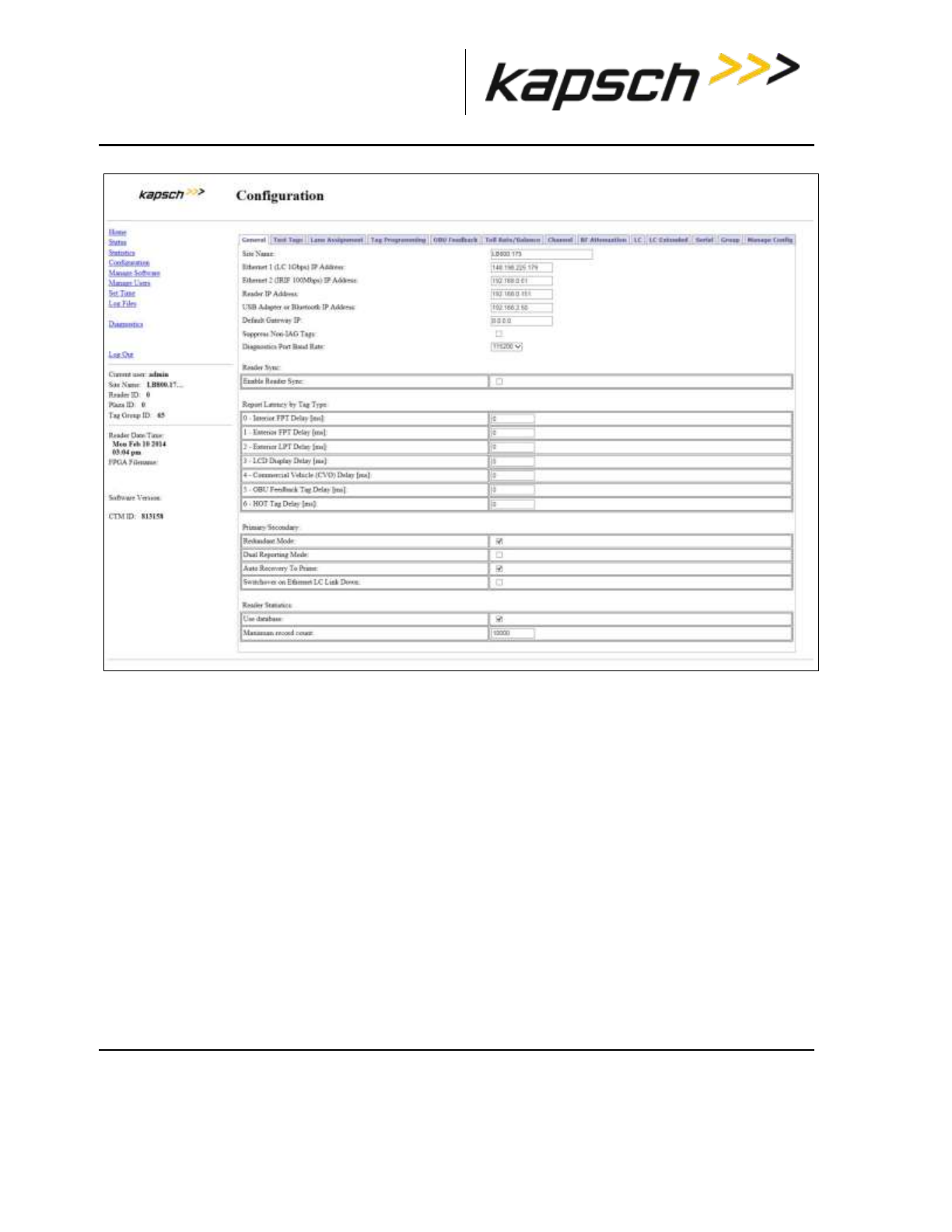
_
JANUS® Multi-Protocol Reader Ver. 2: Operating Instructions
Confidential UM 360463-202 Revision: A12 (Draft) Page 46 of 291
© Kapsch TrafficCom Canada Inc. 2014
These drawings and specifications contain confidential and proprietary information and are the property of Kapsch TrafficCom Canada Inc. and are issued in strict
confidence and will be kept confidential and used solely for the purpose intended and for no other purpose and shall not be transmitted, reproduced, copied, and/or
used as the basis for manufacture or sale of apparatus unless otherwise agreed to in writing by Kapsch TrafficCom Canada Inc.
FILE: MPR2_OPERATIONS_AND_MAINTENANCE-MANUAL_REV A12.DOCX 05/08/2014 11:24
Kapsch TrafficCom
3. Select the Auto Recovery To Prime check box.
4. Press Enter to accept the selection.
Monitoring the Reader
You can monitor and gather information about the Reader from the CTM web interface using the
Status option in the left panel of the screen.
Note: For all of the following procedures, a laptop or desktop computer with a monitor needs to be
connected to the CTM Ethernet 1 port or USB port.
Reader status
The Status page in the CTM web interface displays the state of the communication links, the power
supply modules, and the CTM/CGC2, and is useful for troubleshooting the Reader.
Communications
Table 3-1 lists and describes the fields in the Communications tab on the Status page.
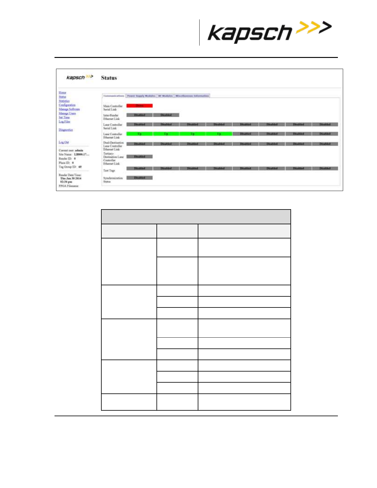
_
JANUS® Multi-Protocol Reader Ver. 2: Operating Instructions
Confidential UM 360463-202 Revision: A12 (Draft) Page 47 of 291
© Kapsch TrafficCom Canada Inc. 2014
These drawings and specifications contain confidential and proprietary information and are the property of Kapsch TrafficCom Canada Inc. and are issued in strict
confidence and will be kept confidential and used solely for the purpose intended and for no other purpose and shall not be transmitted, reproduced, copied, and/or
used as the basis for manufacture or sale of apparatus unless otherwise agreed to in writing by Kapsch TrafficCom Canada Inc.
FILE: MPR2_OPERATIONS_AND_MAINTENANCE-MANUAL_REV A12.DOCX 05/08/2014 11:24
Kapsch TrafficCom
Table 3-1: Communications fields
Communications tab
Field
Status
Description
Main Controller
Serial link
Up
successful link connection
between redundant CTMs
Down
link failure or disabled
(always Down on non-redundant
Readers)
Inter-Reader
Ethernet link
Enabled
successful link connection
Down
link failure
Disabled
link not enabled
Lane Controller
Serial link
Enabled
successful link connection
between CTM (via LPM) and LC
Down
link failure
Disabled
link not enabled
Lane Controller
Ethernet link
Enabled
successful link connection
Down
link failure
Disabled
link not enabled
Test Tags
Enabled
the Reader is configured to
periodically communicate with
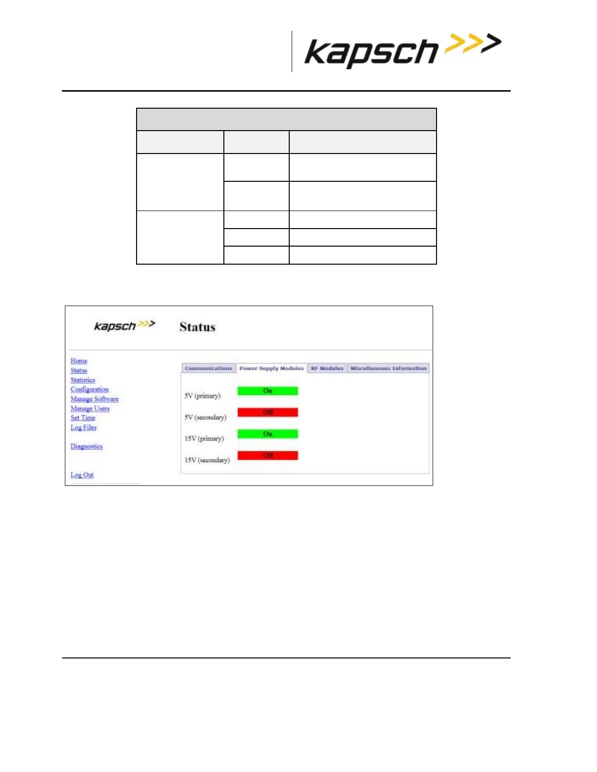
_
JANUS® Multi-Protocol Reader Ver. 2: Operating Instructions
Confidential UM 360463-202 Revision: A12 (Draft) Page 48 of 291
© Kapsch TrafficCom Canada Inc. 2014
These drawings and specifications contain confidential and proprietary information and are the property of Kapsch TrafficCom Canada Inc. and are issued in strict
confidence and will be kept confidential and used solely for the purpose intended and for no other purpose and shall not be transmitted, reproduced, copied, and/or
used as the basis for manufacture or sale of apparatus unless otherwise agreed to in writing by Kapsch TrafficCom Canada Inc.
FILE: MPR2_OPERATIONS_AND_MAINTENANCE-MANUAL_REV A12.DOCX 05/08/2014 11:24
Kapsch TrafficCom
Communications tab
Field
Status
Description
test tags to confirm RF Channel
health
Disabled
test tags are not used to confirm
RF Channel health
Synchronization
Up
successful link connection
Down
link failure
Disabled
synchronization not enabled
Power Supply Module
Table 3-2 lists and describes the fields in the Power Supply Module tab on the Status page.
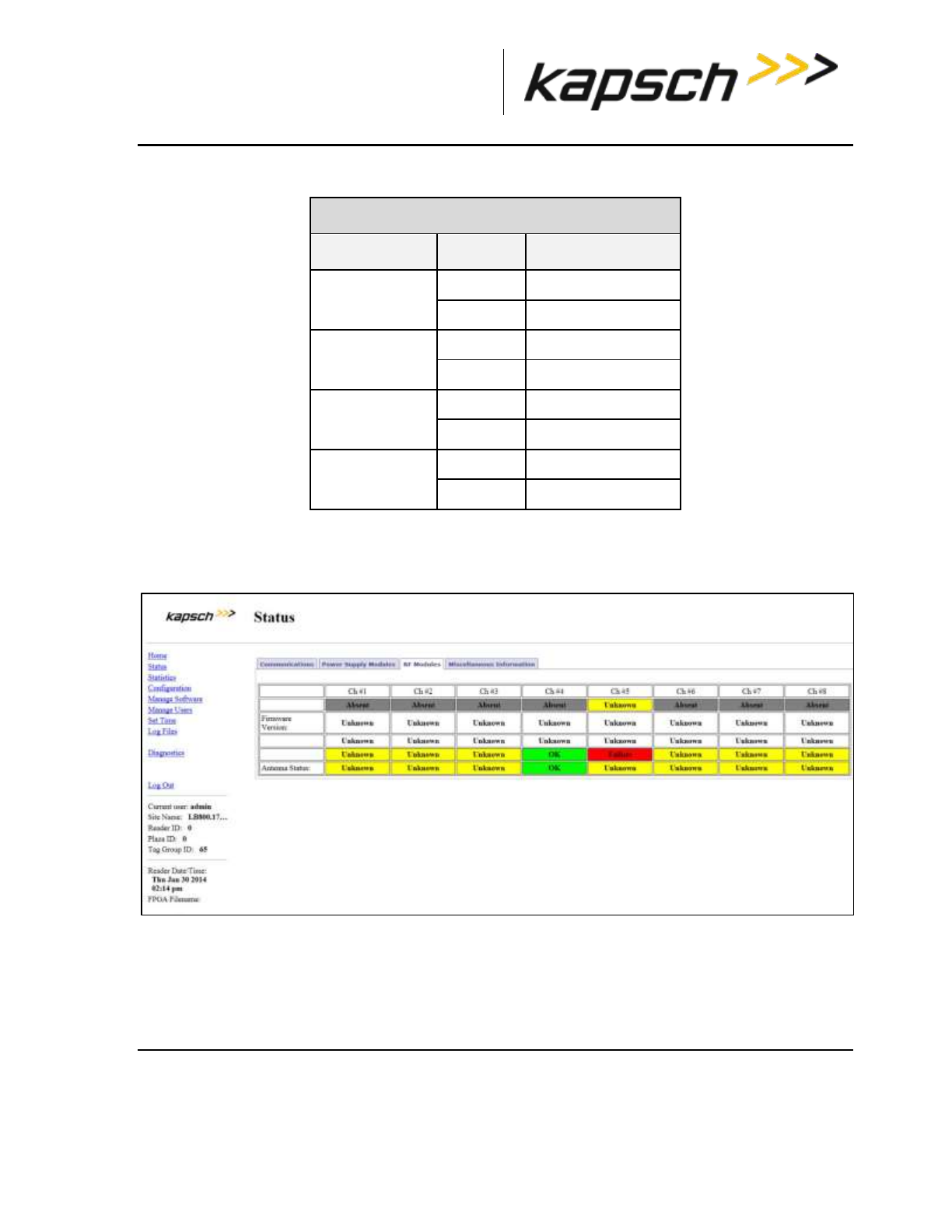
_
JANUS® Multi-Protocol Reader Ver. 2: Operating Instructions
Confidential UM 360463-202 Revision: A12 (Draft) Page 49 of 291
© Kapsch TrafficCom Canada Inc. 2014
These drawings and specifications contain confidential and proprietary information and are the property of Kapsch TrafficCom Canada Inc. and are issued in strict
confidence and will be kept confidential and used solely for the purpose intended and for no other purpose and shall not be transmitted, reproduced, copied, and/or
used as the basis for manufacture or sale of apparatus unless otherwise agreed to in writing by Kapsch TrafficCom Canada Inc.
FILE: MPR2_OPERATIONS_AND_MAINTENANCE-MANUAL_REV A12.DOCX 05/08/2014 11:24
Kapsch TrafficCom
Table 3-2 Power Supply Module fields
Power Supply Modules tab
Field
Status
Description
5V (primary)
On
DC input operational
Off
DC input failure
5V (secondary)
On
DC input operational
Off
DC input failure
15V (primary)
On
DC input operational
Off
DC input failure
15V (secondary)
On
DC input operational
Off
DC input failure
RF Modules
Table 3-3 lists and describes the fields in the RF Modules tab on the Status page.

_
JANUS® Multi-Protocol Reader Ver. 2: Operating Instructions
Confidential UM 360463-202 Revision: A12 (Draft) Page 50 of 291
© Kapsch TrafficCom Canada Inc. 2014
These drawings and specifications contain confidential and proprietary information and are the property of Kapsch TrafficCom Canada Inc. and are issued in strict
confidence and will be kept confidential and used solely for the purpose intended and for no other purpose and shall not be transmitted, reproduced, copied, and/or
used as the basis for manufacture or sale of apparatus unless otherwise agreed to in writing by Kapsch TrafficCom Canada Inc.
FILE: MPR2_OPERATIONS_AND_MAINTENANCE-MANUAL_REV A12.DOCX 05/08/2014 11:24
Kapsch TrafficCom
Table 3-3 RF Modules fields
RF Modules tab
Field
Status
Description
Firmware Version
Absent
Not installed
OK
Successfully installed and verified
Failure
Unsuccessfully installed
Unknown
Status not known
Antenna Status
Absent
Not installed
OK
Receiving and/or transmitting
Failure
Fault in receiving and/or transmitting
Unknown
Status not known

_
JANUS® Multi-Protocol Reader Ver. 2: Operating Instructions
Confidential UM 360463-202 Revision: A12 (Draft) Page 51 of 291
© Kapsch TrafficCom Canada Inc. 2014
These drawings and specifications contain confidential and proprietary information and are the property of Kapsch TrafficCom Canada Inc. and are issued in strict
confidence and will be kept confidential and used solely for the purpose intended and for no other purpose and shall not be transmitted, reproduced, copied, and/or
used as the basis for manufacture or sale of apparatus unless otherwise agreed to in writing by Kapsch TrafficCom Canada Inc.
FILE: MPR2_OPERATIONS_AND_MAINTENANCE-MANUAL_REV A12.DOCX 05/08/2014 11:24
Kapsch TrafficCom
Miscellaneous Information
Table 3-4 lists and describes the fields in the Miscellaneous Information tab on the Status page.

_
JANUS® Multi-Protocol Reader Ver. 2: Operating Instructions
Confidential UM 360463-202 Revision: A12 (Draft) Page 52 of 291
© Kapsch TrafficCom Canada Inc. 2014
These drawings and specifications contain confidential and proprietary information and are the property of Kapsch TrafficCom Canada Inc. and are issued in strict
confidence and will be kept confidential and used solely for the purpose intended and for no other purpose and shall not be transmitted, reproduced, copied, and/or
used as the basis for manufacture or sale of apparatus unless otherwise agreed to in writing by Kapsch TrafficCom Canada Inc.
FILE: MPR2_OPERATIONS_AND_MAINTENANCE-MANUAL_REV A12.DOCX 05/08/2014 11:24
Kapsch TrafficCom
Table 3-4: Miscellaneous Information fields
Miscellaneous Information tab
Field
Status
Description
LC Serial Type
Defined
LC Serial Type is known
Undefined
LC Serial Type is unknown
CTM Position
Primary
The CTM is installed on the primary side
Secondary
The CTM is installed on the secondary
side
Active State
Active
CTM is active
InActive
CTM is not active
CGC Health
Status
Operational
CGC2 is operational
Down
CGC2 Failure
Board
Example:
LB800, LB735
Provides information on the model of
the single board computer (SBC) board
installed Type of Board installed
Other Side
Config
Compare
Communication
Down; Same;
Different
(BETA) Provides an indication as to
configuration state of peer CTM
Communication Down (peer CTM is not
running so configuration state is
unknown)
Same (peer CTM configuration is
identical to this CTM’s configuration)
Different (peer CTM configuration is
different that this CTM’s
configuration)
Front-panel
switch
position
Auto; Primary;
Secondary
Auto, Primary (switch set to Primary
side), Secondary (switch set to
Secondary side).
For a redundant system, the switch
would normally be set to Auto
CFM Status
Present
Indicates normal status
Not Detected
Indicates a problem; call Kapsch Service
Lane Tuning
Mode
Disabled
‘Disabled’ is normal status
Super Frame
Time (μs)
Numerical read
Reader timing information In
microseconds

_
JANUS® Multi-Protocol Reader Ver. 2: Operating Instructions
Confidential UM 360463-202 Revision: A12 (Draft) Page 53 of 291
© Kapsch TrafficCom Canada Inc. 2014
These drawings and specifications contain confidential and proprietary information and are the property of Kapsch TrafficCom Canada Inc. and are issued in strict
confidence and will be kept confidential and used solely for the purpose intended and for no other purpose and shall not be transmitted, reproduced, copied, and/or
used as the basis for manufacture or sale of apparatus unless otherwise agreed to in writing by Kapsch TrafficCom Canada Inc.
FILE: MPR2_OPERATIONS_AND_MAINTENANCE-MANUAL_REV A12.DOCX 05/08/2014 11:24
Kapsch TrafficCom
RF Channel Statistics
The Statistics page displays performance information for each MRFM-S channel. The statistics
displayed do not update automatically as transactions occur. Update the statistics with the latest data
by navigating away from, and then returning to the Statistics page, or by refreshing/reloading your
browser window.
Updates to the statistics pages commence when the Reader begins processing OBU transactions after
startup.
Statistics continue being appended until the system is either stopped and re-started, rebooted, or the
Reset Transaction Statistics button is clicked, which sets the statistics values to zero and updates
commence again.
Reports by channel
This screen lists and graphs reports on channel activity. You can chose to display daily or weekly
reports by clicking the available buttons.
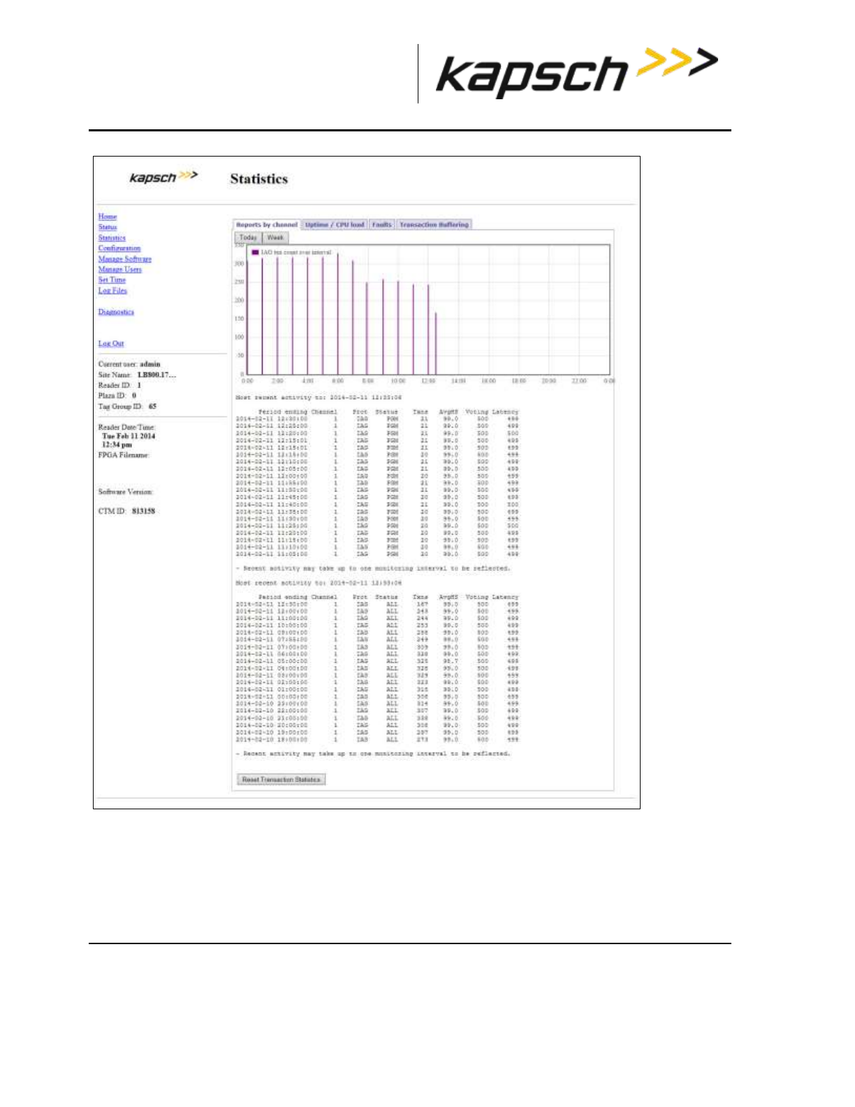
_
JANUS® Multi-Protocol Reader Ver. 2: Operating Instructions
Confidential UM 360463-202 Revision: A12 (Draft) Page 54 of 291
© Kapsch TrafficCom Canada Inc. 2014
These drawings and specifications contain confidential and proprietary information and are the property of Kapsch TrafficCom Canada Inc. and are issued in strict
confidence and will be kept confidential and used solely for the purpose intended and for no other purpose and shall not be transmitted, reproduced, copied, and/or
used as the basis for manufacture or sale of apparatus unless otherwise agreed to in writing by Kapsch TrafficCom Canada Inc.
FILE: MPR2_OPERATIONS_AND_MAINTENANCE-MANUAL_REV A12.DOCX 05/08/2014 11:24
Kapsch TrafficCom
You can reset the values of the report by clicking the Reset Transaction Statistics button.

_
JANUS® Multi-Protocol Reader Ver. 2: Operating Instructions
Confidential UM 360463-202 Revision: A12 (Draft) Page 55 of 291
© Kapsch TrafficCom Canada Inc. 2014
These drawings and specifications contain confidential and proprietary information and are the property of Kapsch TrafficCom Canada Inc. and are issued in strict
confidence and will be kept confidential and used solely for the purpose intended and for no other purpose and shall not be transmitted, reproduced, copied, and/or
used as the basis for manufacture or sale of apparatus unless otherwise agreed to in writing by Kapsch TrafficCom Canada Inc.
FILE: MPR2_OPERATIONS_AND_MAINTENANCE-MANUAL_REV A12.DOCX 05/08/2014 11:24
Kapsch TrafficCom
Table 3-5 Reports by Channel
Reports by Channel tab
Field
Description
Period ending
The date and time that the statistics in the browser window were
updated. Navigate away from and then return to the Statistics
page, or refresh/reload your browser screen to update the
statistics.
Channel
The RF Channel that the statistics in that row represent.
Prot
Protocol being used by the Reader
Status
TBD
Txns
The number of trnasactions performed in a period
AvgHS
The average number of handshakes over the total transactions
with the primary or secondary side active
Voting
TBD
Latency
The average latency time to report transactions
Uptime / CPU Load
This report lists and graphs the date and time of the reader activity measured in HoursUp and the
number of CPU Loads involved.
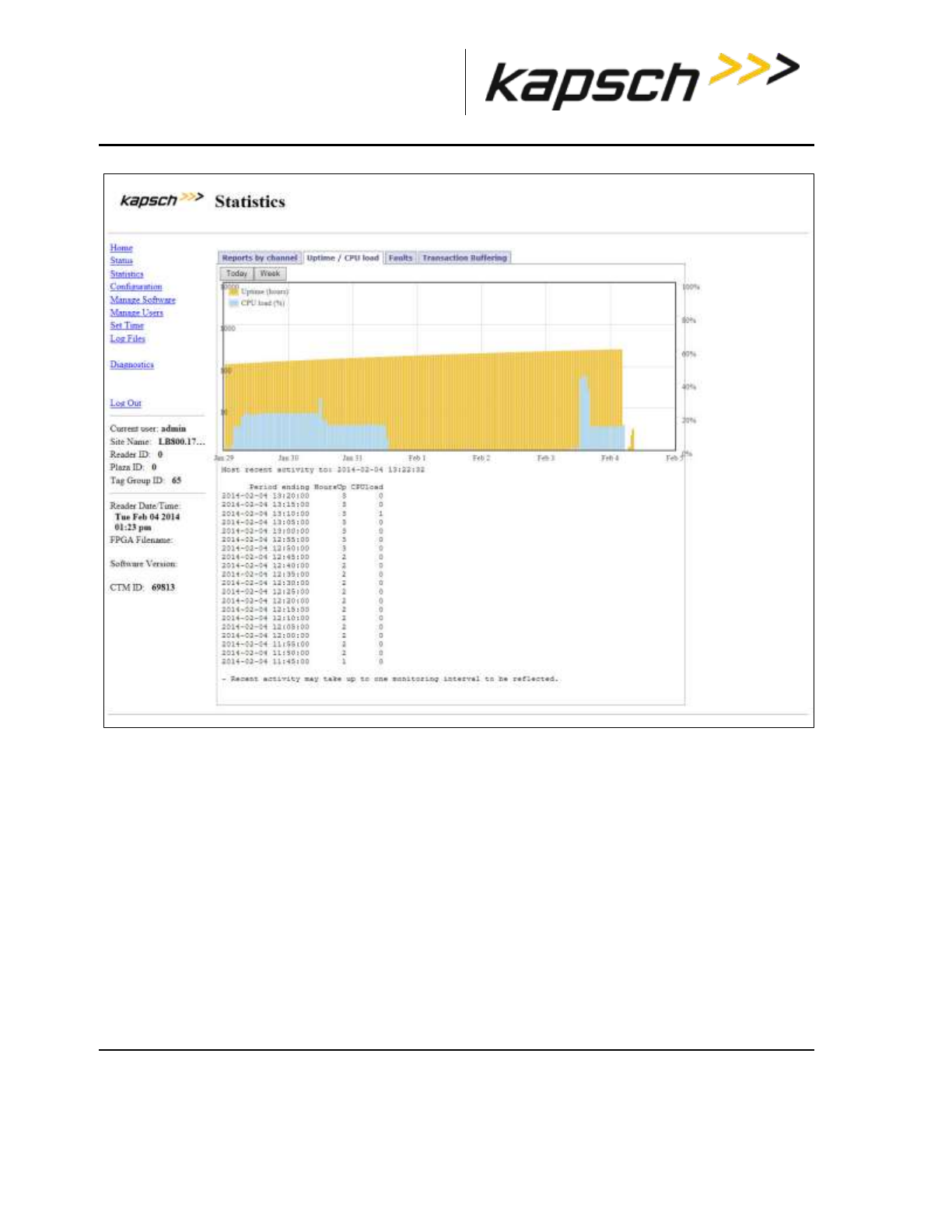
_
JANUS® Multi-Protocol Reader Ver. 2: Operating Instructions
Confidential UM 360463-202 Revision: A12 (Draft) Page 56 of 291
© Kapsch TrafficCom Canada Inc. 2014
These drawings and specifications contain confidential and proprietary information and are the property of Kapsch TrafficCom Canada Inc. and are issued in strict
confidence and will be kept confidential and used solely for the purpose intended and for no other purpose and shall not be transmitted, reproduced, copied, and/or
used as the basis for manufacture or sale of apparatus unless otherwise agreed to in writing by Kapsch TrafficCom Canada Inc.
FILE: MPR2_OPERATIONS_AND_MAINTENANCE-MANUAL_REV A12.DOCX 05/08/2014 11:24
Kapsch TrafficCom
Faults
This screen lists and graphs faults and reports them by type according to a color code.
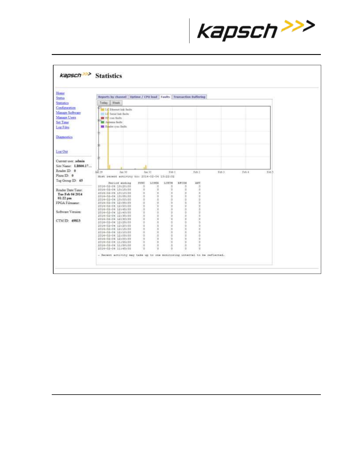
_
JANUS® Multi-Protocol Reader Ver. 2: Operating Instructions
Confidential UM 360463-202 Revision: A12 (Draft) Page 57 of 291
© Kapsch TrafficCom Canada Inc. 2014
These drawings and specifications contain confidential and proprietary information and are the property of Kapsch TrafficCom Canada Inc. and are issued in strict
confidence and will be kept confidential and used solely for the purpose intended and for no other purpose and shall not be transmitted, reproduced, copied, and/or
used as the basis for manufacture or sale of apparatus unless otherwise agreed to in writing by Kapsch TrafficCom Canada Inc.
FILE: MPR2_OPERATIONS_AND_MAINTENANCE-MANUAL_REV A12.DOCX 05/08/2014 11:24
Kapsch TrafficCom
Transaction Buffering
Transaction buffering shows the user how much each channel is using for buffering. The following
screen shows an example.
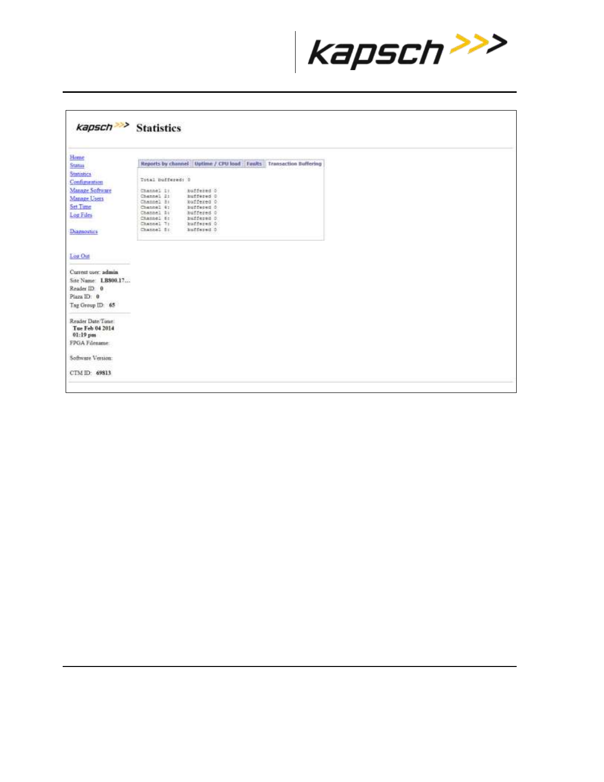
_
JANUS® Multi-Protocol Reader Ver. 2: Operating Instructions
Confidential UM 360463-202 Revision: A12 (Draft) Page 58 of 291
© Kapsch TrafficCom Canada Inc. 2014
These drawings and specifications contain confidential and proprietary information and are the property of Kapsch TrafficCom Canada Inc. and are issued in strict
confidence and will be kept confidential and used solely for the purpose intended and for no other purpose and shall not be transmitted, reproduced, copied, and/or
used as the basis for manufacture or sale of apparatus unless otherwise agreed to in writing by Kapsch TrafficCom Canada Inc.
FILE: MPR2_OPERATIONS_AND_MAINTENANCE-MANUAL_REV A12.DOCX 05/08/2014 11:24
Kapsch TrafficCom
Note: Each side reports transactions that occurred while being active.
Monitoring OBU transactions as they occur via the Diagnostics page
Monitoring OBU transactions from the Diagnostics page is a better alternative to viewing transactions
from a transaction log on the Log Files page because the transactions on the Diagnostics page are
updated automatically. However, transactions that occurred before the Diagnostics page was
accessed can only be viewed from the transaction log.
The Display Transactions option displays both active and passive transactions.
Prerequisites: Connect the service laptop to the Reader configuration port to access the CTM web
Refer to Connecting a service laptop to the Reader, page 40. You must have Advanced User
permissions.
Note: The computer must have Java version 6.0 installed (see www.java.com).
1. Select the Diagnostics link from the left side panel.
Result: The following Diagnostics Page appears.
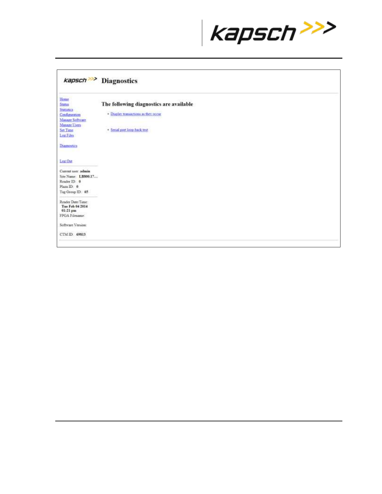
_
JANUS® Multi-Protocol Reader Ver. 2: Operating Instructions
Confidential UM 360463-202 Revision: A12 (Draft) Page 59 of 291
© Kapsch TrafficCom Canada Inc. 2014
These drawings and specifications contain confidential and proprietary information and are the property of Kapsch TrafficCom Canada Inc. and are issued in strict
confidence and will be kept confidential and used solely for the purpose intended and for no other purpose and shall not be transmitted, reproduced, copied, and/or
used as the basis for manufacture or sale of apparatus unless otherwise agreed to in writing by Kapsch TrafficCom Canada Inc.
FILE: MPR2_OPERATIONS_AND_MAINTENANCE-MANUAL_REV A12.DOCX 05/08/2014 11:24
Kapsch TrafficCom
2. An authentication window may appear on the Diagnostics Page when accessed the first time. If it
appears, enter a valid user name and password.
Note: To avoid having to re-enter authentication information on the Diagnostics Page, click the Save this
password in your password list button.
Result: After the Java program starts, the Tag Transaction window appears. All OBU transactions for the
Reader display automatically. The display update stops if someone updates the Reader software or
reboots the Reader.
Note: If a second computer or second browser window is used to access the Diagnostics Page, new
transactions will no longer be displayed in the first browser window.
Continuously logging transactions to a USB flash drive
This procedure outlines how to have transaction log files automatically saved and continuously updated
on a USB flash drive.
Prerequisites: A USB flash drive is inserted into one of the CTM USB ports.
Connect the service laptop to the Reader configuration port to access the CTM web interface. Refer to
Connecting a service laptop to the Reader, page 40. You must have View Log Files and Manage Log
Files permissions.
1. Select the Log Files link on the left side panel of the screen.
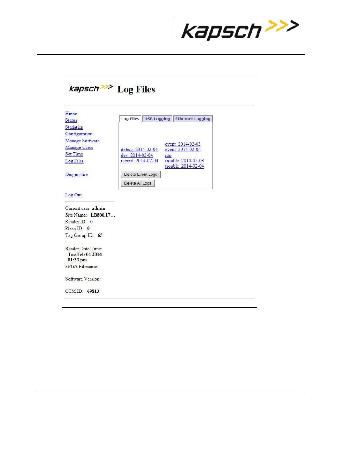
_
JANUS® Multi-Protocol Reader Ver. 2: Operating Instructions
Confidential UM 360463-202 Revision: A12 (Draft) Page 60 of 291
© Kapsch TrafficCom Canada Inc. 2014
These drawings and specifications contain confidential and proprietary information and are the property of Kapsch TrafficCom Canada Inc. and are issued in strict
confidence and will be kept confidential and used solely for the purpose intended and for no other purpose and shall not be transmitted, reproduced, copied, and/or
used as the basis for manufacture or sale of apparatus unless otherwise agreed to in writing by Kapsch TrafficCom Canada Inc.
FILE: MPR2_OPERATIONS_AND_MAINTENANCE-MANUAL_REV A12.DOCX 05/08/2014 11:24
Kapsch TrafficCom
Result: The following Log Files page appears.
2. Click the USB Logging tab.
Result: The following screen appears.
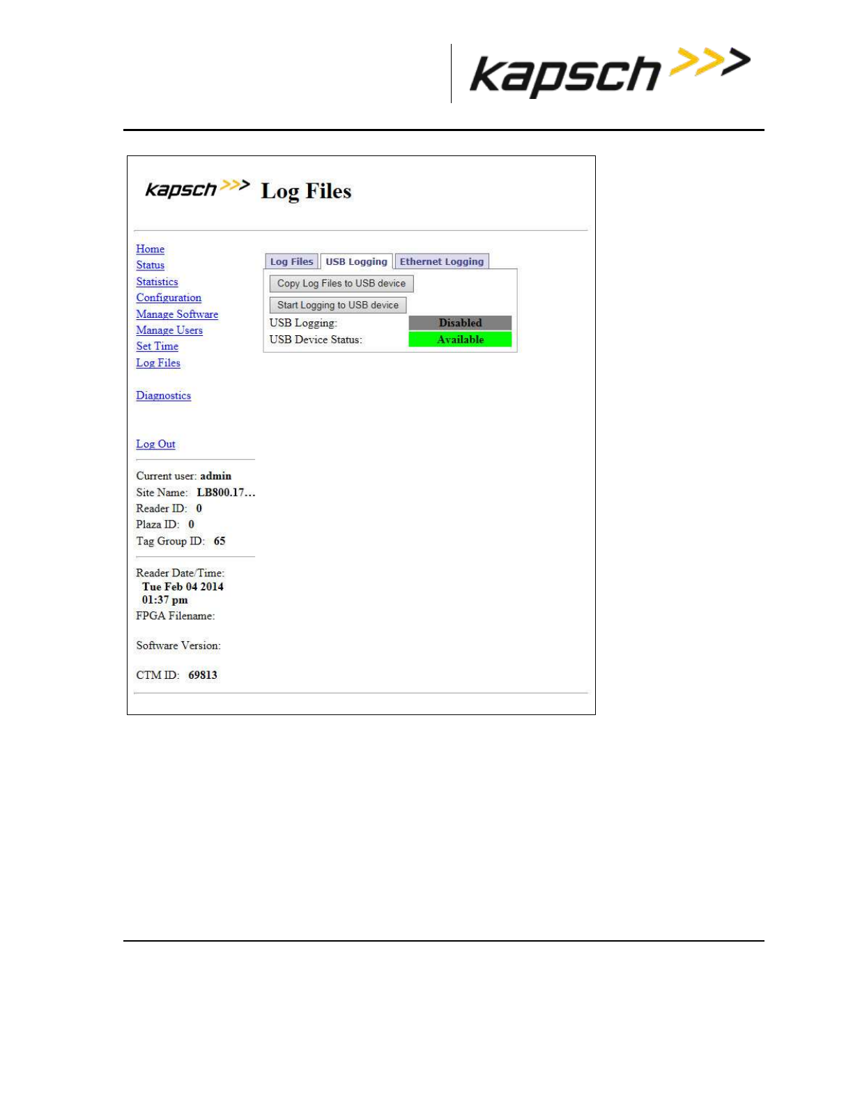
_
JANUS® Multi-Protocol Reader Ver. 2: Operating Instructions
Confidential UM 360463-202 Revision: A12 (Draft) Page 61 of 291
© Kapsch TrafficCom Canada Inc. 2014
These drawings and specifications contain confidential and proprietary information and are the property of Kapsch TrafficCom Canada Inc. and are issued in strict
confidence and will be kept confidential and used solely for the purpose intended and for no other purpose and shall not be transmitted, reproduced, copied, and/or
used as the basis for manufacture or sale of apparatus unless otherwise agreed to in writing by Kapsch TrafficCom Canada Inc.
FILE: MPR2_OPERATIONS_AND_MAINTENANCE-MANUAL_REV A12.DOCX 05/08/2014 11:24
Kapsch TrafficCom
3. Click the Start Logging to USB Device button.
Result: The following screen message appears.
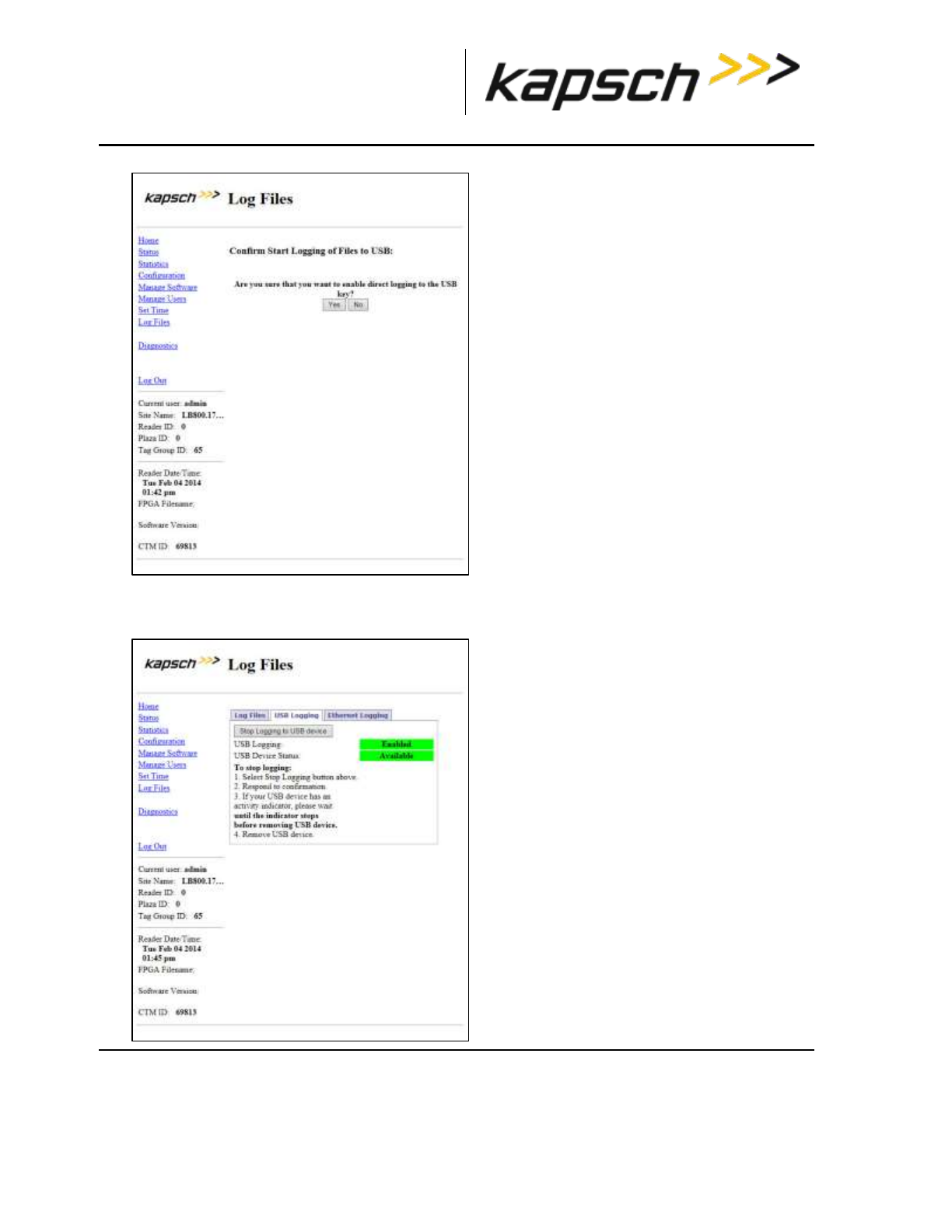
_
JANUS® Multi-Protocol Reader Ver. 2: Operating Instructions
Confidential UM 360463-202 Revision: A12 (Draft) Page 62 of 291
© Kapsch TrafficCom Canada Inc. 2014
These drawings and specifications contain confidential and proprietary information and are the property of Kapsch TrafficCom Canada Inc. and are issued in strict
confidence and will be kept confidential and used solely for the purpose intended and for no other purpose and shall not be transmitted, reproduced, copied, and/or
used as the basis for manufacture or sale of apparatus unless otherwise agreed to in writing by Kapsch TrafficCom Canada Inc.
FILE: MPR2_OPERATIONS_AND_MAINTENANCE-MANUAL_REV A12.DOCX 05/08/2014 11:24
Kapsch TrafficCom
4. Click the Yes button.
Result: The following screen message appears.
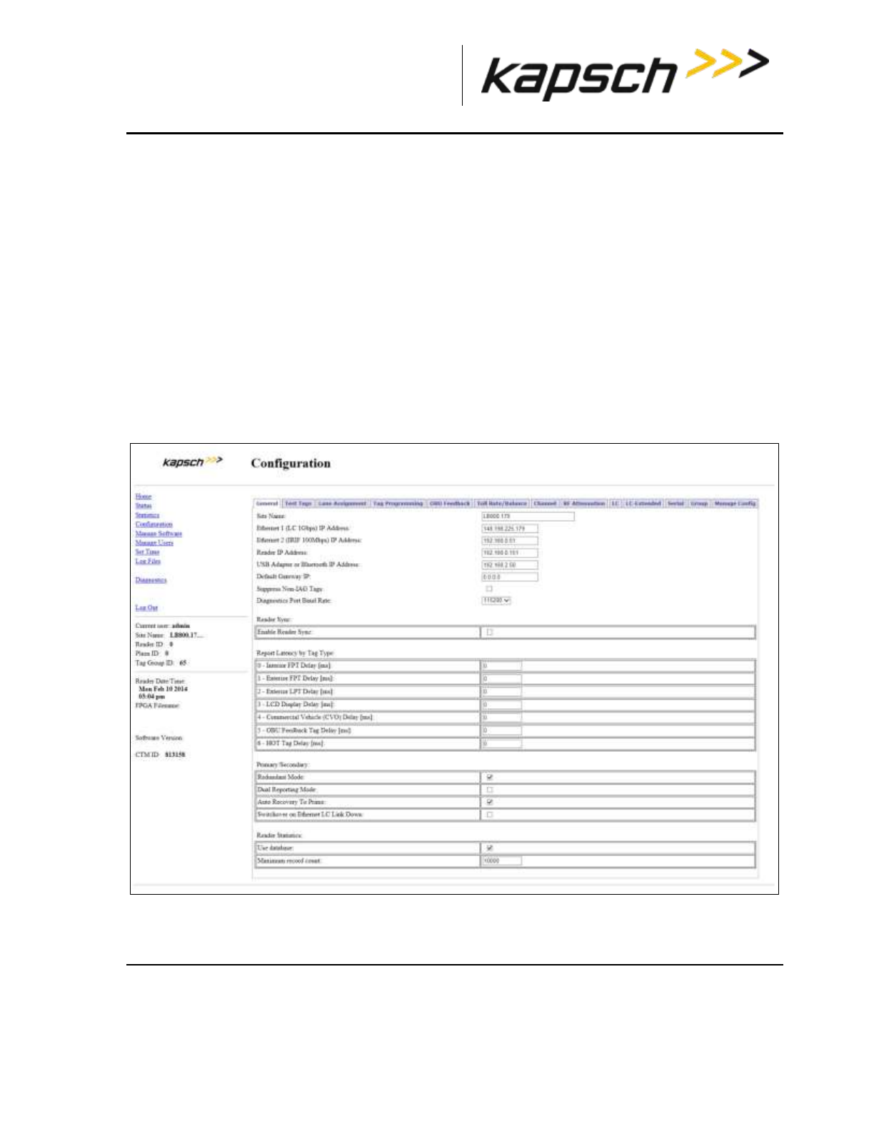
_
JANUS® Multi-Protocol Reader Ver. 2: Operating Instructions
Confidential UM 360463-202 Revision: A12 (Draft) Page 63 of 291
© Kapsch TrafficCom Canada Inc. 2014
These drawings and specifications contain confidential and proprietary information and are the property of Kapsch TrafficCom Canada Inc. and are issued in strict
confidence and will be kept confidential and used solely for the purpose intended and for no other purpose and shall not be transmitted, reproduced, copied, and/or
used as the basis for manufacture or sale of apparatus unless otherwise agreed to in writing by Kapsch TrafficCom Canada Inc.
FILE: MPR2_OPERATIONS_AND_MAINTENANCE-MANUAL_REV A12.DOCX 05/08/2014 11:24
Kapsch TrafficCom
Note: The USB Logging changes its display from Disabled to Enabled, and USB Device Status remains
at Available to indicate that a connection between the Reader and the USB flash drive and log files can
get copied and updated to the USB device in realtime when required.
Note: You can click the Copy Log Files to USB device button if you just want to copy the present list of
log files to the USB device.
OBU Programming
The Reader can write data to an OBU as it passes through a toll plaza. The following procedures
outline how to enable OBU programming and how to configure the data that is written to the OBUs.
Prerequisites: Connect the service laptop to the Reader configuration port to access the CTM web
interface. Refer to Connecting a service laptop to the Reader, page 40.
1. Select the Configuration link on the left side panel of the screen.
Result: The following screen appears.
2. Click the Tag Programming tab.
Result: The following screen appears.
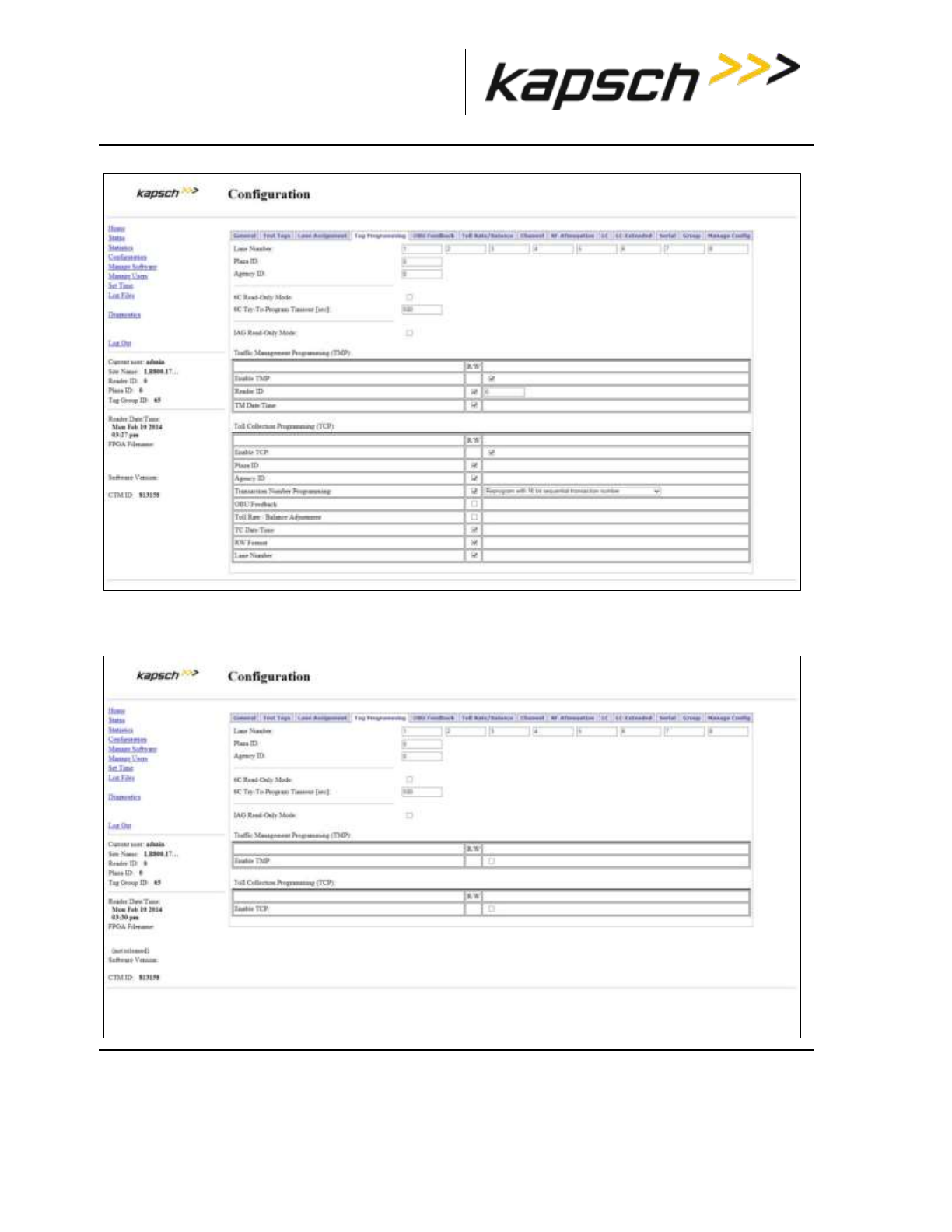
_
JANUS® Multi-Protocol Reader Ver. 2: Operating Instructions
Confidential UM 360463-202 Revision: A12 (Draft) Page 64 of 291
© Kapsch TrafficCom Canada Inc. 2014
These drawings and specifications contain confidential and proprietary information and are the property of Kapsch TrafficCom Canada Inc. and are issued in strict
confidence and will be kept confidential and used solely for the purpose intended and for no other purpose and shall not be transmitted, reproduced, copied, and/or
used as the basis for manufacture or sale of apparatus unless otherwise agreed to in writing by Kapsch TrafficCom Canada Inc.
FILE: MPR2_OPERATIONS_AND_MAINTENANCE-MANUAL_REV A12.DOCX 05/08/2014 11:24
Kapsch TrafficCom
3. Clear the check boxes.
Result: The following screen appears.
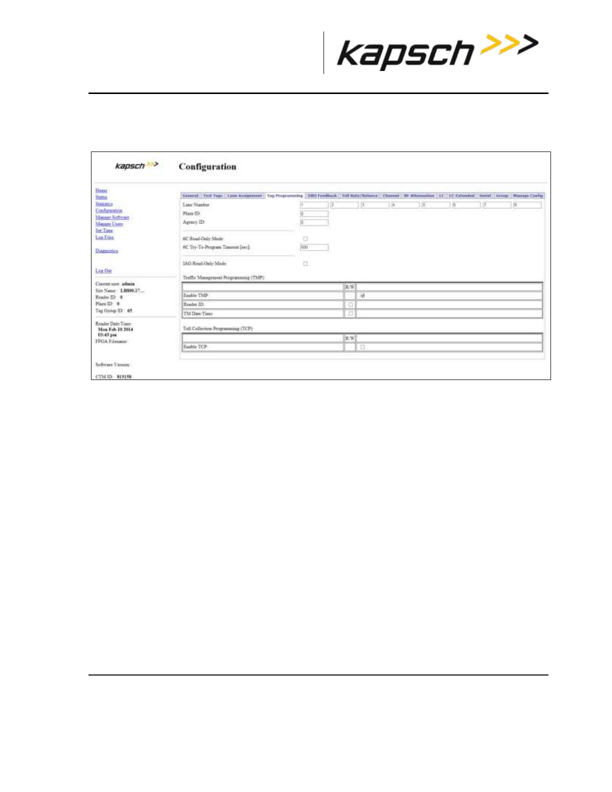
_
JANUS® Multi-Protocol Reader Ver. 2: Operating Instructions
Confidential UM 360463-202 Revision: A12 (Draft) Page 65 of 291
© Kapsch TrafficCom Canada Inc. 2014
These drawings and specifications contain confidential and proprietary information and are the property of Kapsch TrafficCom Canada Inc. and are issued in strict
confidence and will be kept confidential and used solely for the purpose intended and for no other purpose and shall not be transmitted, reproduced, copied, and/or
used as the basis for manufacture or sale of apparatus unless otherwise agreed to in writing by Kapsch TrafficCom Canada Inc.
FILE: MPR2_OPERATIONS_AND_MAINTENANCE-MANUAL_REV A12.DOCX 05/08/2014 11:24
Kapsch TrafficCom
Configuring OBU programming for Traffic Management Applications
1. From the Tag Programming screen, select the Enable TMP check box.
Result: The following screen appears.
4. Select the Reader ID check box to enable writing the Reader ID to OBUs.
5. Enter a unique Reader ID.
6. Select the TM Date/Time check box to write the Reader TM time to OBUs.
7. Press Enter to accept the selections.
Configuring OBU programming for Toll Collection applications
1. From the above Tag Programming screen, select the Enable TCP check box.
Result: The following screen appears.
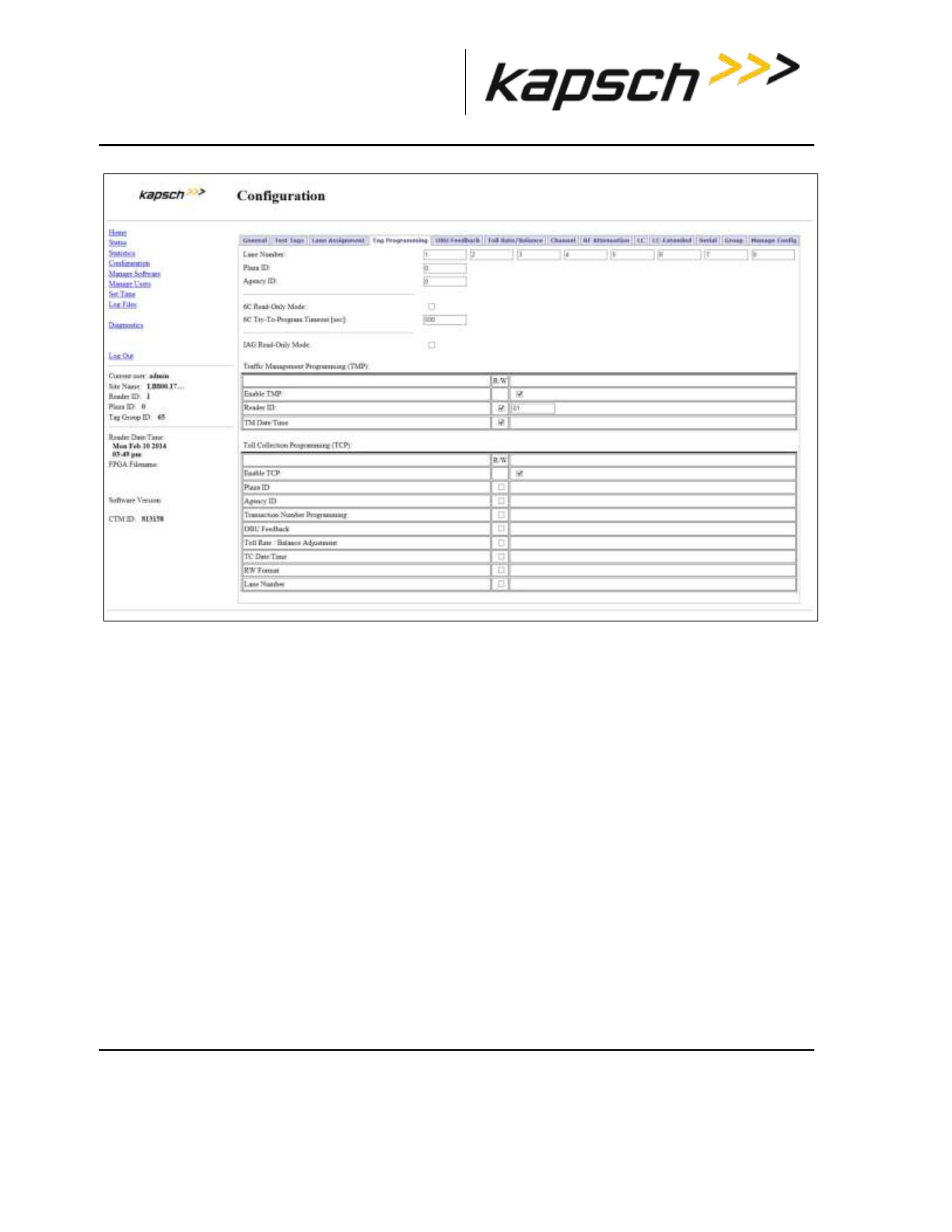
_
JANUS® Multi-Protocol Reader Ver. 2: Operating Instructions
Confidential UM 360463-202 Revision: A12 (Draft) Page 66 of 291
© Kapsch TrafficCom Canada Inc. 2014
These drawings and specifications contain confidential and proprietary information and are the property of Kapsch TrafficCom Canada Inc. and are issued in strict
confidence and will be kept confidential and used solely for the purpose intended and for no other purpose and shall not be transmitted, reproduced, copied, and/or
used as the basis for manufacture or sale of apparatus unless otherwise agreed to in writing by Kapsch TrafficCom Canada Inc.
FILE: MPR2_OPERATIONS_AND_MAINTENANCE-MANUAL_REV A12.DOCX 05/08/2014 11:24
Kapsch TrafficCom
Note: If not already enabled, check and configure the Plaza ID before enabling OBU feedback. The
Plaza ID field is not accessible once OBU feedback is enabled.
2. Enter the Plaza ID and Agency ID in the fields.
3. Select the Transaction Number Programming check box to choose how the Reader determines the toll
transaction number.
4. Click the Transaction Number Programming drop-down box
Result: The following screen appears.
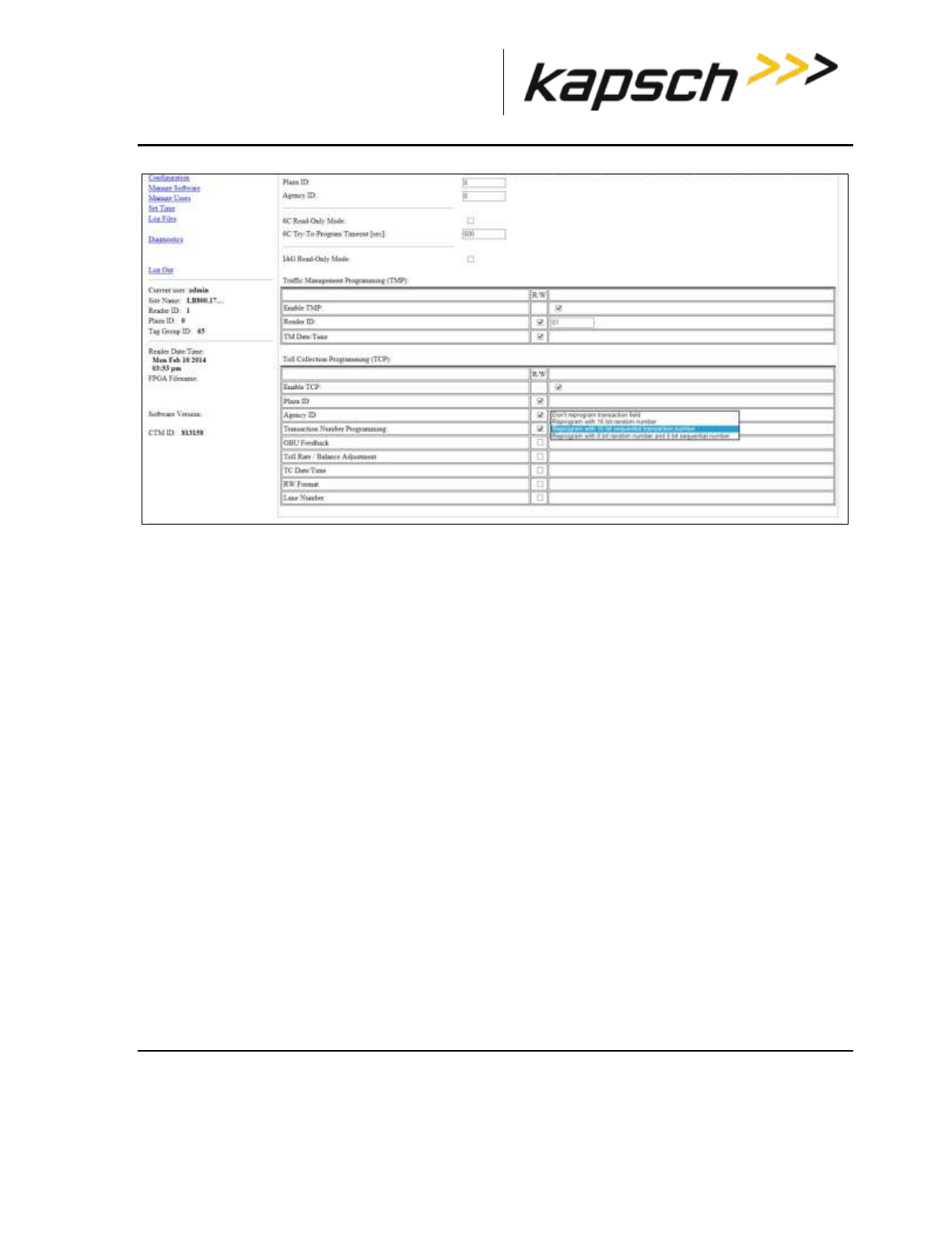
_
JANUS® Multi-Protocol Reader Ver. 2: Operating Instructions
Confidential UM 360463-202 Revision: A12 (Draft) Page 67 of 291
© Kapsch TrafficCom Canada Inc. 2014
These drawings and specifications contain confidential and proprietary information and are the property of Kapsch TrafficCom Canada Inc. and are issued in strict
confidence and will be kept confidential and used solely for the purpose intended and for no other purpose and shall not be transmitted, reproduced, copied, and/or
used as the basis for manufacture or sale of apparatus unless otherwise agreed to in writing by Kapsch TrafficCom Canada Inc.
FILE: MPR2_OPERATIONS_AND_MAINTENANCE-MANUAL_REV A12.DOCX 05/08/2014 11:24
Kapsch TrafficCom
5. Select the desired transaction numbering calculation from the drop-down box.
6. Select the TC Date/Time check box to write the transaction time to the OBU.
7. Select the RW Format check box to determine how the scratchpad data is encoded when written to
OBUs.
8. Select the OBU Feedback check box to enable OBU feedback, ensuring that you first enabled and
configured the Plaza ID in step 7 on page 66.
9. Assign a Lane Number to each RF channel. When a transaction occurs between an OBU and a channel,
the Lane Number specified here will be used when recording the transaction in OBU memory.
10. Select the OBU Feedback tab.
11. Select either Type 1 or Type 2 feedback.
12. Select the desired audible feedback to control OBU beeping when a transaction occurs.
13. Select the desired visual feedback to control OBU LED flashing when a transaction occurs.
14. Press Enter to accept selections.
Configuring Toll charges
The Reader can deduct toll charges from a toll/balance OBU based on a number of parameters. BAT 1
tolling deducts charges based on the vehicle type and the lane the vehicle is in when it passes through
the toll plaza. BAT 2 tolling deducts charges based on distance by determining the toll plazas the
vehicle entered and exited on the highway.
Prerequisites: You must have Advanced User permissions.
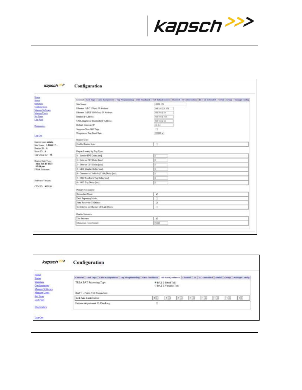
_
JANUS® Multi-Protocol Reader Ver. 2: Operating Instructions
Confidential UM 360463-202 Revision: A12 (Draft) Page 68 of 291
© Kapsch TrafficCom Canada Inc. 2014
These drawings and specifications contain confidential and proprietary information and are the property of Kapsch TrafficCom Canada Inc. and are issued in strict
confidence and will be kept confidential and used solely for the purpose intended and for no other purpose and shall not be transmitted, reproduced, copied, and/or
used as the basis for manufacture or sale of apparatus unless otherwise agreed to in writing by Kapsch TrafficCom Canada Inc.
FILE: MPR2_OPERATIONS_AND_MAINTENANCE-MANUAL_REV A12.DOCX 05/08/2014 11:24
Kapsch TrafficCom
BAT 1 tolling (deducting charges based on lane and vehicle type)
1. Select the Configuration link on the left side panel of the screen.
Result: The following screen appears.
2. Select the Toll/Rate Balance tab
Result: The following screen appears.
3. Select BAT 1 - Fixed Toll as the TRBA BAT Processing Type.
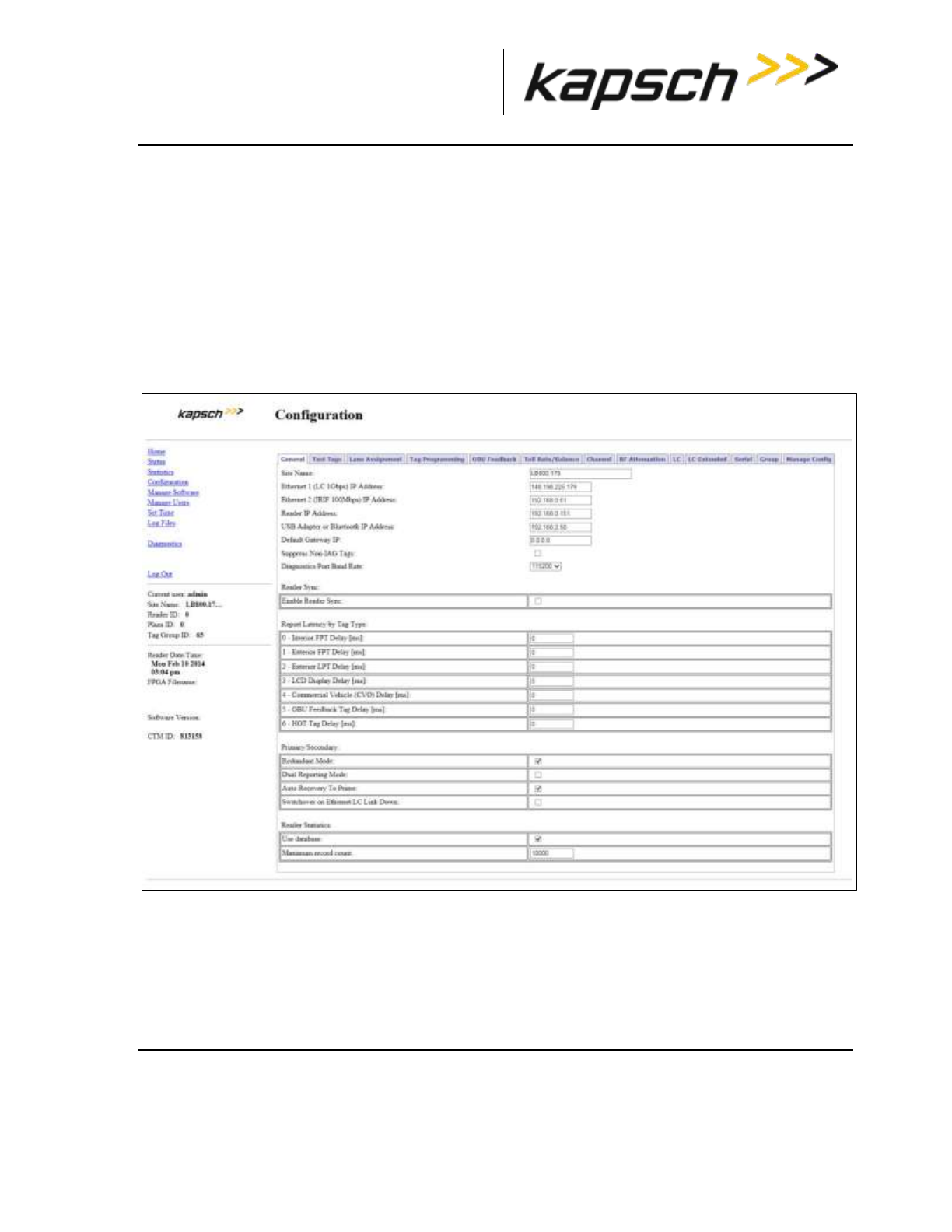
_
JANUS® Multi-Protocol Reader Ver. 2: Operating Instructions
Confidential UM 360463-202 Revision: A12 (Draft) Page 69 of 291
© Kapsch TrafficCom Canada Inc. 2014
These drawings and specifications contain confidential and proprietary information and are the property of Kapsch TrafficCom Canada Inc. and are issued in strict
confidence and will be kept confidential and used solely for the purpose intended and for no other purpose and shall not be transmitted, reproduced, copied, and/or
used as the basis for manufacture or sale of apparatus unless otherwise agreed to in writing by Kapsch TrafficCom Canada Inc.
FILE: MPR2_OPERATIONS_AND_MAINTENANCE-MANUAL_REV A12.DOCX 05/08/2014 11:24
Kapsch TrafficCom
4. Select one of four Toll Rate Tables for each channel, which determines the charge for the lane associated
with each channel.
5. Select the Enforce Adjustment ID Checking check box to limit how frequently the balance can be
updated.
6. Press Enter to accept the values.
Result: The Reader now charges OBUs based on your choices.
BAT 2 tolling (deducting charges based on entry and exit location)
1. Select the Configuration link on the left side panel of the screen.
Result: The following screen appears.
2. Select the Toll Rate/Balance tab
3. Select BAT 2 - Variable Toll as the TRBA BAT Processing Type.
Result: The following screen appears.
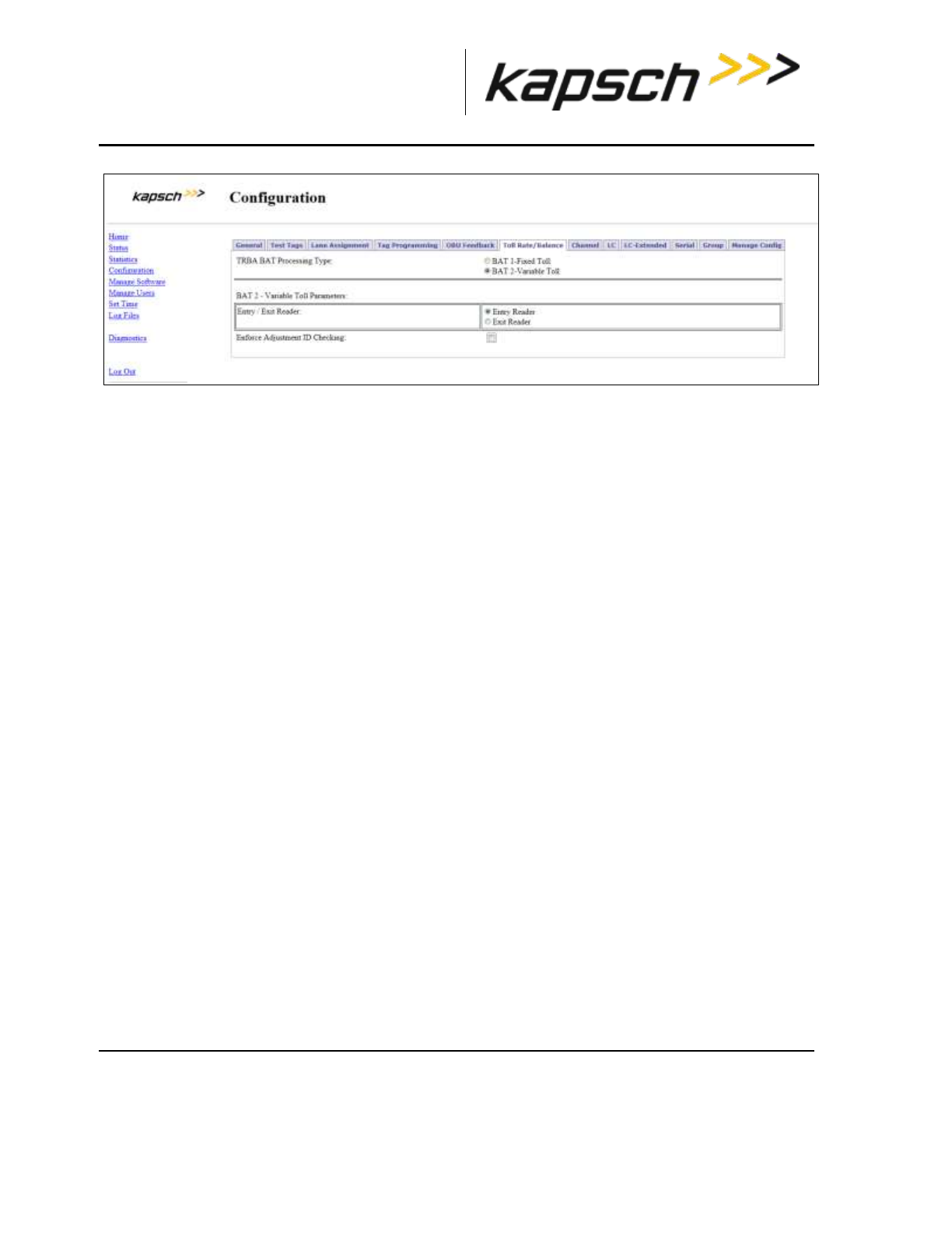
_
JANUS® Multi-Protocol Reader Ver. 2: Operating Instructions
Confidential UM 360463-202 Revision: A12 (Draft) Page 70 of 291
© Kapsch TrafficCom Canada Inc. 2014
These drawings and specifications contain confidential and proprietary information and are the property of Kapsch TrafficCom Canada Inc. and are issued in strict
confidence and will be kept confidential and used solely for the purpose intended and for no other purpose and shall not be transmitted, reproduced, copied, and/or
used as the basis for manufacture or sale of apparatus unless otherwise agreed to in writing by Kapsch TrafficCom Canada Inc.
FILE: MPR2_OPERATIONS_AND_MAINTENANCE-MANUAL_REV A12.DOCX 05/08/2014 11:24
Kapsch TrafficCom
Note: For Readers at entry locations, select Entry Reader; for Readers at exit locations, select Exit
Reader.
4. Select the Enforce Adjustment ID Checking check box to limit how frequently the balance can be
updated.
5. Press Enter to accept the values.
Result: The Reader now charges OBUs based on your choices.
Configuring Protocols
Configure the Reader to interact with various protocol tags.
Prerequisites: You must have Advanced User permissions.
1. After selecting the Configuration link on the left side, select the Channel tab,
Result: The following screen appears.
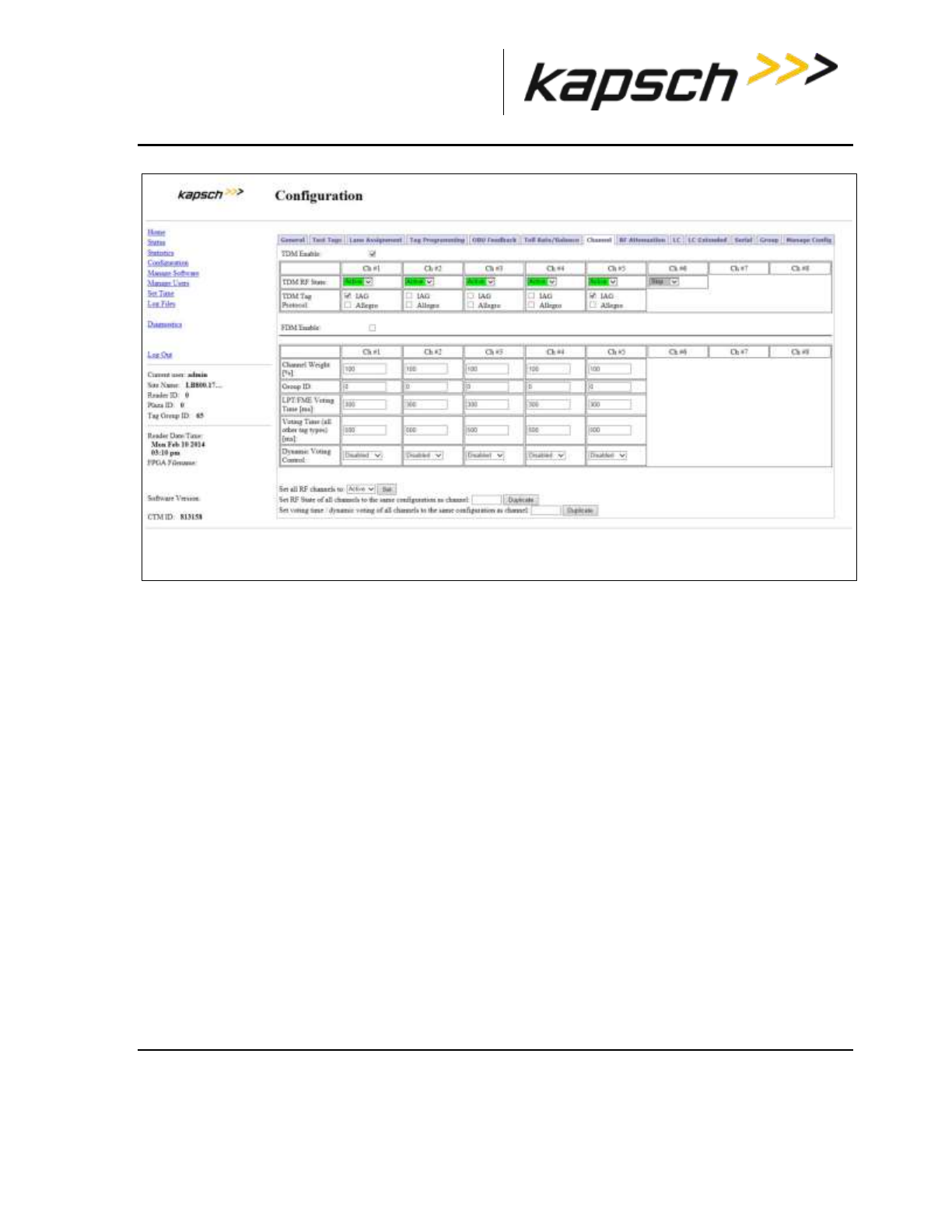
_
JANUS® Multi-Protocol Reader Ver. 2: Operating Instructions
Confidential UM 360463-202 Revision: A12 (Draft) Page 71 of 291
© Kapsch TrafficCom Canada Inc. 2014
These drawings and specifications contain confidential and proprietary information and are the property of Kapsch TrafficCom Canada Inc. and are issued in strict
confidence and will be kept confidential and used solely for the purpose intended and for no other purpose and shall not be transmitted, reproduced, copied, and/or
used as the basis for manufacture or sale of apparatus unless otherwise agreed to in writing by Kapsch TrafficCom Canada Inc.
FILE: MPR2_OPERATIONS_AND_MAINTENANCE-MANUAL_REV A12.DOCX 05/08/2014 11:24
Kapsch TrafficCom
2. When the reader leaves the factory, only those protocols selected by the customer are available for
configuration. All other protocols will be de-selected.
3. Select each channel and use the TDM RF State and FDM RF State to enable or disable a channel.
4. Select the frequency for each channel by using the FDM Frequency (MHZ) selection.
Note: This should only be performed with Kapsch technical support.
5. Select the specific combination of protocols desired.
Note: This should only be performed with Kapsch Technical Support.

_
JANUS® Multi-Protocol Reader Ver. 2: Operating Instructions
Confidential UM 360463-202: A12 (Draft) Page 72 of 291
© Kapsch TrafficCom Canada Inc. 2014
These drawings and specifications contain confidential and proprietary information and are the property of Kapsch TrafficCom Canada Inc. and are issued in strict confidence and will be kept confidential and used solely for the purpose
intended and for no other purpose and shall not be transmitted, reproduced, copied, and/or used as the basis for manufacture or sale of apparatus unless otherwise agreed to in writing by Kapsch TrafficCom Canada Inc.
FILE: MPR2_OPERATIONS_AND_MAINTENANCE-MANUAL_REV A12.DOCX 05/08/2014 11:24
Kapsch TrafficCom
Configuration
The following table lists and describes the commands and controls that can be deployed in the various Configuration screens that are available to a
user.
Table 3-6 Commands and Controls
Command
How is this command
executed?
Who can
execute this
command?
Parameter
Name
Default
Parameter
Value
Parameter
Range/Options
What does this
command do?
What is the purpose
of this command?
Home
In the navigation side bar:
Click Home.
anyone
N/A
N/A
N/A
displays the Main
Page in the CTM
web interface.
Used to return to the
main page.
Status
In the navigation side bar:
Click Status.
anyone
N/A
N/A
N/A
displays the Status
page in the CTM
web interface.
Used to monitor
communication,
power supply, CTM
status and CGC health
See System
Identification for more
explanation of the
button.

_
JANUS® Multi-Protocol Reader Ver. 2: Operating Instructions
Confidential UM 360463-202: A12 (Draft) Page 73 of 291
© Kapsch TrafficCom Canada Inc. 2014
These drawings and specifications contain confidential and proprietary information and are the property of Kapsch TrafficCom Canada Inc. and are issued in strict confidence and will be kept confidential and used solely for the purpose
intended and for no other purpose and shall not be transmitted, reproduced, copied, and/or used as the basis for manufacture or sale of apparatus unless otherwise agreed to in writing by Kapsch TrafficCom Canada Inc.
FILE: MPR2_OPERATIONS_AND_MAINTENANCE-MANUAL_REV A12.DOCX 05/08/2014 11:24
Kapsch TrafficCom
Command
How is this command
executed?
Who can
execute this
command?
Parameter
Name
Default
Parameter
Value
Parameter
Range/Options
What does this
command do?
What is the
purpose of this
command?
Statistics
In the navigation side bar:
Click Statistics.
anyone
N/A
N/A
N/A
displays the Statistics
page in the CTM web
interface.
Used to view
Reports by
channel ,
Low/Early Reads,
Transaction
Buffering
statistics.
Note: The Reset
Transaction
Statistics button
is used to start a
new statistical
record.
Configuration
In the navigation side bar:
Click Configuration.
anyone
N/A
N/A
N/A
displays the Configuration
page in the CTM web
interface.
Used to access a
variety of Reader
configuration
parameters.
Manage
Software
In the navigation side bar:
Click Manage Software
user with
Manage
Software
permissions
N/A
N/A
N/A
displays the Software
Management page in the
CTM web interface.
Used to access
upload and
verify, activate,
and delete
software
commands and
the Reboot
button to reboot
the Reader.

_
JANUS® Multi-Protocol Reader Ver. 2: Operating Instructions
Confidential UM 360463-202: A12 (Draft) Page 74 of 291
© Kapsch TrafficCom Canada Inc. 2014
These drawings and specifications contain confidential and proprietary information and are the property of Kapsch TrafficCom Canada Inc. and are issued in strict confidence and will be kept confidential and used solely for the purpose
intended and for no other purpose and shall not be transmitted, reproduced, copied, and/or used as the basis for manufacture or sale of apparatus unless otherwise agreed to in writing by Kapsch TrafficCom Canada Inc.
FILE: MPR2_OPERATIONS_AND_MAINTENANCE-MANUAL_REV A12.DOCX 05/08/2014 11:24
Kapsch TrafficCom
Command
How is this command
executed?
Who can
execute this
command?
Parameter
Name
Default
Parameter
Value
Parameter
Range/Options
What does this
command do?
What is the
purpose of this
command?
Manage Users
In the navigation side bar:
Click Manage Users.
user with User
Admin
permissions
N/A
N/A
N/A
displays the User
Management page in the
CTM web interface
Used to access
user profiles,
create new
users, delete
users, change
permissions,
change
passwords.
Change
Password
In the navigation side bar:
Click Change Password.
user WITHOUT
User Admin
permissions
N/A
N/A
N/A
displays a User
Management page
limited to commands for
changing passwords
to change the
password of the
user currently
logged into the
CTM web
interface
Set Time
In the navigation side bar:
Click Set Time.
anyone
N/A
N/A
N/A
displays the Time
Management page in the
CTM web interface
to
Disable/Enable
Network Time
Protocol (NTP)
access NTP
servers IPv4
addresses and
select a new
time zone

_
JANUS® Multi-Protocol Reader Ver. 2: Operating Instructions
Confidential UM 360463-202: A12 (Draft) Page 75 of 291
© Kapsch TrafficCom Canada Inc. 2014
These drawings and specifications contain confidential and proprietary information and are the property of Kapsch TrafficCom Canada Inc. and are issued in strict confidence and will be kept confidential and used solely for the purpose
intended and for no other purpose and shall not be transmitted, reproduced, copied, and/or used as the basis for manufacture or sale of apparatus unless otherwise agreed to in writing by Kapsch TrafficCom Canada Inc.
FILE: MPR2_OPERATIONS_AND_MAINTENANCE-MANUAL_REV A12.DOCX 05/08/2014 11:24
Kapsch TrafficCom
Command
How is this command
executed?
Who can
execute this
command?
Parameter
Name
Default
Parameter
Value
Parameter
Range/Options
What does this
command do?
What is the
purpose of this
command?
Log Files
In the navigation side bar:
Click Log Files.
user with
View Log Files
permission
N/A
N/A
N/A
displays the Log Files page
in the CTM web interface.
Also displays the USB
Logging tab and the
Ethernet Logging tab.
to view ,
manage or copy
log files,
depending on
user permissions
Diagnostics
In the navigation side bar:
Click Diagnostics.
user with
Advanced
User
permissions
N/A
N/A
N/A
displays the Diagnostic
Page in the CTM web
interface
Used for the
following
Diagnostics:
Static and
Dynamic
Margin
Maps
Displaying
transactions
as they
occur
Serial port
loop-back
test
Log Out
In the navigation side bar:
Click Log Out.
anyone
N/A
N/A
N/A
immediately logs the
current user out of the
CTM web interface
Used to log out
of the CTM web
interface

_
JANUS® Multi-Protocol Reader Ver. 2: Operating Instructions
Confidential UM 360463-202: A12 (Draft) Page 76 of 291
© Kapsch TrafficCom Canada Inc. 2014
These drawings and specifications contain confidential and proprietary information and are the property of Kapsch TrafficCom Canada Inc. and are issued in strict confidence and will be kept confidential and used solely for the purpose
intended and for no other purpose and shall not be transmitted, reproduced, copied, and/or used as the basis for manufacture or sale of apparatus unless otherwise agreed to in writing by Kapsch TrafficCom Canada Inc.
FILE: MPR2_OPERATIONS_AND_MAINTENANCE-MANUAL_REV A12.DOCX 05/08/2014 11:24
Kapsch TrafficCom
Command
How is this command
executed?
Who can
execute this
command?
Parameter
Name
Default
Parameter
Value
Parameter
Range/Options
What does this
command do?
What is the
purpose of this
command?
System
Identification
From the Miscellaneous
Information tab on the Status
page:
Click the System Identification
button.
anyone
N/A
N/A
N/A
causes the CTM MC LED
to flash green-red-amber-
green three times
Used to confirm
which CTM web
interface is being
viewed and that
the computer is
successfully
communicating
with the CTM
Reset
Transaction
Statistics
From the Reports by channel
tab on the Statistics page:
Click Reset Transaction
Statistics button
user with
Advanced
User
permissions
N/A
N/A
N/A
sets all statistical values at
0
Used to allow
statistics to be
tracked from a
known starting
point
Site Name
From the General tab on the
Configuration page:
Type a Reader name in Site
Name text, then, click outside
the field, press Enter, or select
a different tab.
anyone
SITENM
no default
value
32
sets the site name used in
the log file strings and is
used in the name of the
configuration files
Used to identify
which Reader
the log files and
configuration
files originated
from
Ethernet 1 IP
(LC 1Gbps)
Address
From the General tab on the
Configuration page:
Type a ETHERNET 1 port IP
address in Ethernet 1 (LC
1Gbps) IP Address field, then, ,
click outside the field, press
Enter, or select a different tab.
anyone
LETHIF
192.168.1.50
N/A
sets the IP address for the
ETHERNET 1 port on the
CTM
Used to specify
an appropriate
ETHERNET 1 IP
address when
configuring an LC
network

_
JANUS® Multi-Protocol Reader Ver. 2: Operating Instructions
Confidential UM 360463-202: A12 (Draft) Page 77 of 291
© Kapsch TrafficCom Canada Inc. 2014
These drawings and specifications contain confidential and proprietary information and are the property of Kapsch TrafficCom Canada Inc. and are issued in strict confidence and will be kept confidential and used solely for the purpose
intended and for no other purpose and shall not be transmitted, reproduced, copied, and/or used as the basis for manufacture or sale of apparatus unless otherwise agreed to in writing by Kapsch TrafficCom Canada Inc.
FILE: MPR2_OPERATIONS_AND_MAINTENANCE-MANUAL_REV A12.DOCX 05/08/2014 11:24
Kapsch TrafficCom
Command
How is this command
executed?
Who can
execute this
command?
Parameter
Name
Default
Parameter
Value
Parameter
Range/Options
What does this
command do?
What is the
purpose of this
command?
Ethernet 2 IP
(IRIF 100Mbps)
Address:
From the General tab on the
Configuration page:
Type an ETHERNET 2 port IP
address in the Ethernet 2 (IRIF
100Mbps) IP Address field,
then, , click outside the field,
press Enter, or select a
different tab.
anyone
PRIMIP
192.168.0.50
Primary
192.168.0.51
Secondary
N/A
sets the IP address for the
ETHERNET 2 port on the
CTM
Used to specify
an appropriate
ETHERNET 2 IP
address when
configuring an IR
network
IP Address
From the General tab on the
Configuration page:
Type an IP address in IP
Address field in General tab of
the Configuration page, then, ,
click outside the field, press
Enter, or select a different tab.
user with
Advanced
User
permissions
SCNDIP
192.168.0.51
N/A
sets the IP address to the
secondary side of the
reader
Assigns a unique
IPv4 address
(e.g.
192.168.0.51) to
the secondary
side of the
reader. This
address should
be provided by
the SI network
planner.

_
JANUS® Multi-Protocol Reader Ver. 2: Operating Instructions
Confidential UM 360463-202: A12 (Draft) Page 78 of 291
© Kapsch TrafficCom Canada Inc. 2014
These drawings and specifications contain confidential and proprietary information and are the property of Kapsch TrafficCom Canada Inc. and are issued in strict confidence and will be kept confidential and used solely for the purpose
intended and for no other purpose and shall not be transmitted, reproduced, copied, and/or used as the basis for manufacture or sale of apparatus unless otherwise agreed to in writing by Kapsch TrafficCom Canada Inc.
FILE: MPR2_OPERATIONS_AND_MAINTENANCE-MANUAL_REV A12.DOCX 05/08/2014 11:24
Kapsch TrafficCom
Command
How is this command
executed?
Who can
execute this
command?
Parameter
Name
Default
Parameter
Value
Parameter
Range/Options
What does this
command do?
What is the
purpose of this
command?
Reader IP
address
From the General tab on the
Configuration page:
Type a Reader IP address in
Reader IP Address field in
General tab of the
Configuration page, then, ,
click outside the field, press
Enter, or select a different tab.
user with
Advanced
User
permissions
READIP
10.0.0.50.0
N/A
sets the IP address for the
Reader
Used to specify a
unique IP
address for the
Reader when
configuring an IR
network
USB Adapter IP
or Bluetooth IP
Address
From the General tab on the
Configuration page:
Type an IP address in the USB
Adapter IP Address field, then,
, click outside the field, press
Enter, or select a different tab.
user with
Advanced
User
permissions
USB_IP
192.168.2.50
N/A
sets the IP address for the
USB-to-Ethernet adapter
connected to one of the
CTM USB ports
Used to specify a
unique IP
address for the
USB-to-Ethernet
adapter for
connecting a
service laptop
computer to a
CTM USB port

_
JANUS® Multi-Protocol Reader Ver. 2: Operating Instructions
Confidential UM 360463-202: A12 (Draft) Page 79 of 291
© Kapsch TrafficCom Canada Inc. 2014
These drawings and specifications contain confidential and proprietary information and are the property of Kapsch TrafficCom Canada Inc. and are issued in strict confidence and will be kept confidential and used solely for the purpose
intended and for no other purpose and shall not be transmitted, reproduced, copied, and/or used as the basis for manufacture or sale of apparatus unless otherwise agreed to in writing by Kapsch TrafficCom Canada Inc.
FILE: MPR2_OPERATIONS_AND_MAINTENANCE-MANUAL_REV A12.DOCX 05/08/2014 11:24
Kapsch TrafficCom
Command
How is this command
executed?
Who can
execute this
command?
Parameter
Name
Default
Parameter
Value
Parameter
Range/Options
What does this
command do?
What is the
purpose of this
command?
Default
Gateway IP
From the General tab on the
Configuration page:
Type an IP address in the
Default Gateway IP Address
field, then, , click outside the
field, press Enter, or select a
different tab.
anyone
DFGWIP
0.0.0.0.0
N/A
tells the Reader the
default gateway IP
address of the gateway
device
Used to allow
the Reader on a
network to
connect to a
larger network
(such as the
Internet) via a
gateway device
(such as a
router)
Suppress Non-
IAG Tags
From the General tab on the
Configuration page:
Select Suppress Non-IAG Tags
check box, then, , click outside
the field, press Enter, or select
a different tab.
anyone
NONIAG
1 (Enabled)
0 (Disabled)
1 (Enabled)
Disabled: All transactions
are reported
Enabled: suppresses
reporting of OBUs not
matching the Group ID
that the Reader is
provisioned
Used to prevent
incompatible
report formats
from being sent
to the LC

_
JANUS® Multi-Protocol Reader Ver. 2: Operating Instructions
Confidential UM 360463-202: A12 (Draft) Page 80 of 291
© Kapsch TrafficCom Canada Inc. 2014
These drawings and specifications contain confidential and proprietary information and are the property of Kapsch TrafficCom Canada Inc. and are issued in strict confidence and will be kept confidential and used solely for the purpose
intended and for no other purpose and shall not be transmitted, reproduced, copied, and/or used as the basis for manufacture or sale of apparatus unless otherwise agreed to in writing by Kapsch TrafficCom Canada Inc.
FILE: MPR2_OPERATIONS_AND_MAINTENANCE-MANUAL_REV A12.DOCX 05/08/2014 11:24
Kapsch TrafficCom
Command
How is this command
executed?
Who can
execute this
command?
Parameter
Name
Default
Parameter
Value
Parameter
Range/Options
What does this
command do?
What is the
purpose of this
command?
Diagnostics
Port Baud Rate
From the General tab on the
Configuration page:
Select a baud rate from the
Diagnostics Port Baud Rate
drop-down box, then, , click
outside the field, press Enter,
or select a different tab.
anyone
DIAGBD
0 (9600)
0 (9600)
1 (19200)
2 (38400)
3 (57600)
4 (115200)
sets baud rate of
DIAGNOSTICS PORT on
the CTM
Used to establish
a baud rate for
connecting a
service laptop
computer to the
Reader via the
CTM
DIAGNOSTICS
PORT
Reader Sync:
Enable Reader
Sync
From the General tab on the
Configuration page:
Select the Enable Reader Sync
check box, then, , click outside
the field, press Enter, or select
a different tab.
anyone
RFSYNC
0 (Disabled)
0 (Disabled)
1 (Enabled)
Disabled: Reader RF
interrogation is not
synchronized with other
Readers
Enabled: Reader RF
interrogation is
synchronized with other
Readers in the sync
network
Used to
synchronize
superframes
between
Readers
connected
together in a
synchronization
network

_
JANUS® Multi-Protocol Reader Ver. 2: Operating Instructions
Confidential UM 360463-202: A12 (Draft) Page 81 of 291
© Kapsch TrafficCom Canada Inc. 2014
These drawings and specifications contain confidential and proprietary information and are the property of Kapsch TrafficCom Canada Inc. and are issued in strict confidence and will be kept confidential and used solely for the purpose
intended and for no other purpose and shall not be transmitted, reproduced, copied, and/or used as the basis for manufacture or sale of apparatus unless otherwise agreed to in writing by Kapsch TrafficCom Canada Inc.
FILE: MPR2_OPERATIONS_AND_MAINTENANCE-MANUAL_REV A12.DOCX 05/08/2014 11:24
Kapsch TrafficCom
Command
How is this command
executed?
Who can
execute this
command?
Parameter
Name
Default
Parameter
Value
Parameter
Range/Options
What does this
command do?
What is the
purpose of this
command?
Superframe
Sync Skip
From the General tab on the
Configuration page:
Select either Sync to
superframe or Sync to every
other superframe, then, , click
outside the field, press Enter,
or select a different tab.
user with
Advanced
User
permissions
RFSKSK
0 (Sync to
every
superframe
enabled)
0 (Sync to
every
superframe)
1 (Sync to
every other
superframe)
specifies whether the
Reader tries to sync every
superframe or every other
superframe
Used to allow
Readers with
different
superframe sizes
to sync after the
same number of
frames
Add 2 Dummy
Frames
From the General tab on the
Configuration page:
Select either No or Yes, then, ,
click outside the field, press
Enter, or select a different tab.
user with
Advanced
User
permissions
RFADD2
0 (No)
0 (No)
1 (Yes)
No: dummy frames are
not added to superframe
Yes: dummy frames are
added to superframe.
Used to allow
Readers with
different
superframe sizes
to sync after the
same number of
frames
Type Of Reader
Syncing To
From the General tab on the
Configuration page:
Select either JANUS or Badger
from the drop-down box, then,
click outside the field, press
Enter, or select a different tab.
anyone
SYNCTO
0 (JANUS)
0 (JANUS)
1 (Badger)
JANUS: normal frame rate
is used for
synchronization
Badger: Reader
synchronization is
adjusted to Badger frame
rate
Used to cause
JANUS® Readers
to adjust to the
same frame rate
as BADGER
Readers

_
JANUS® Multi-Protocol Reader Ver. 2: Operating Instructions
Confidential UM 360463-202: A12 (Draft) Page 82 of 291
© Kapsch TrafficCom Canada Inc. 2014
These drawings and specifications contain confidential and proprietary information and are the property of Kapsch TrafficCom Canada Inc. and are issued in strict confidence and will be kept confidential and used solely for the purpose
intended and for no other purpose and shall not be transmitted, reproduced, copied, and/or used as the basis for manufacture or sale of apparatus unless otherwise agreed to in writing by Kapsch TrafficCom Canada Inc.
FILE: MPR2_OPERATIONS_AND_MAINTENANCE-MANUAL_REV A12.DOCX 05/08/2014 11:24
Kapsch TrafficCom
Command
How is this command
executed?
Who can
execute this
command?
Parameter
Name
Default
Parameter
Value
Parameter
Range/Options
What does this
command do?
What is the
purpose of this
command?
Report Latency by Tag Type:
0 - Interior FPT
Delay [ms]
From the General tab on the
Configuration page:
Enter a time (in milliseconds) in
the 0- Interior FPT Delay field,
then, , click outside the field,
press Enter, or select a
different tab.
user with
Advanced
User
permissions
LYCTL0
0
0-5000
sets report delay time in
milliseconds for Interior
FTP OBUs (Type 0)
Used to slow
down the
transaction
report of Type 0
OBUs to the LC
for those legacy
sites where the
LC is expecting
BADGER Reader
timing
1 - Exterior FPT
Delay [ms]
From the General tab on the
Configuration page:
Enter a time (in milliseconds) in
the Exterior FPT Delay field,
then, , click outside the field,
press Enter, or select a
different tab.
user with
Advanced
User
permissions
LYCTL1
0
0-5000
sets report delay time in
milliseconds for Exterior
FTP OBUs (Type 1).
Used to slow
down the
transaction
report of Type 1
OBUs to the LC
for those legacy
sites where the
LC is expecting
BADGER Reader
timing

_
JANUS® Multi-Protocol Reader Ver. 2: Operating Instructions
Confidential UM 360463-202: A12 (Draft) Page 83 of 291
© Kapsch TrafficCom Canada Inc. 2014
These drawings and specifications contain confidential and proprietary information and are the property of Kapsch TrafficCom Canada Inc. and are issued in strict confidence and will be kept confidential and used solely for the purpose
intended and for no other purpose and shall not be transmitted, reproduced, copied, and/or used as the basis for manufacture or sale of apparatus unless otherwise agreed to in writing by Kapsch TrafficCom Canada Inc.
FILE: MPR2_OPERATIONS_AND_MAINTENANCE-MANUAL_REV A12.DOCX 05/08/2014 11:24
Kapsch TrafficCom
Command
How is this command
executed?
Who can
execute this
command?
Parameter
Name
Default
Parameter
Value
Parameter
Range/Options
What does this
command do?
What is the
purpose of this
command?
2 - Exterior LPT
Delay [ms]
From the General tab on the
Configuration page:
Enter a time (in milliseconds) in
the Exterior LPT Delay field,
then, , click outside the field,
press Enter, or select a
different tab.
user with
Advanced
User
permissions
LYCTL2
0
0-5000
sets report delay time in
milliseconds for Exterior
LPT OBUs (Type 2).
Used to slow
down the
transaction
report of Type 2
OBUs to the LC
for those legacy
sites where the
LC is expecting
BADGER Reader
timing
3 - LCD Display
Delay [ms]
From the General tab on the
Configuration page:
Enter a time (in milliseconds) in
the LCD Display Delay field,
then, , click outside the field,
press Enter, or select a
different tab.
user with
Advanced
User
permissions
LYCTL3
0
0-5000
sets report delay time in
milliseconds for LCD
Display OBUs (Type 3).
Used to slow
down the
transaction
report of Type 3
OBUs to the LC
for those legacy
sites where the
LC is expecting
BADGER Reader
timing

_
JANUS® Multi-Protocol Reader Ver. 2: Operating Instructions
Confidential UM 360463-202: A12 (Draft) Page 84 of 291
© Kapsch TrafficCom Canada Inc. 2014
These drawings and specifications contain confidential and proprietary information and are the property of Kapsch TrafficCom Canada Inc. and are issued in strict confidence and will be kept confidential and used solely for the purpose
intended and for no other purpose and shall not be transmitted, reproduced, copied, and/or used as the basis for manufacture or sale of apparatus unless otherwise agreed to in writing by Kapsch TrafficCom Canada Inc.
FILE: MPR2_OPERATIONS_AND_MAINTENANCE-MANUAL_REV A12.DOCX 05/08/2014 11:24
Kapsch TrafficCom
Command
How is this command
executed?
Who can
execute this
command?
Parameter
Name
Default
Parameter
Value
Parameter
Range/Options
What does this
command do?
What is the
purpose of this
command?
4 - Commercial
Vehicle (CVO)
Delay [ms]
From the General tab on the
Configuration page:
Enter a time (in milliseconds) in
the Commercial Vehicle (CVO)
Delay field, then, , click outside
the field, press Enter, or select
a different tab.
user with
Advanced
User
permissions
LYCTL4
0
0-5000
sets report delay time in
milliseconds for CVO
OBUs (Type 4).
Used to slow
down the
transaction
report of Type 4
OBUs to the LC
for those legacy
sites where the
LC is expecting
BADGER Reader
timing
5 - OBU
Feedback Tag
Delay [ms]
From the General tab on the
Configuration page:
Enter a time (in milliseconds) in
the OBU Feedback Tag Delay
field, then, , click outside the
field, press Enter, or select a
different tab.
user with
Advanced
User
permissions
LYCTL5
0
0-5000
sets report delay time in
milliseconds for CVO
OBUs (Type 5).
Used to slow
down the
transaction
report of Type 5
OBUs to the LC
for those legacy
sites where the
LC is expecting
BADGER Reader
timing

_
JANUS® Multi-Protocol Reader Ver. 2: Operating Instructions
Confidential UM 360463-202: A12 (Draft) Page 85 of 291
© Kapsch TrafficCom Canada Inc. 2014
These drawings and specifications contain confidential and proprietary information and are the property of Kapsch TrafficCom Canada Inc. and are issued in strict confidence and will be kept confidential and used solely for the purpose
intended and for no other purpose and shall not be transmitted, reproduced, copied, and/or used as the basis for manufacture or sale of apparatus unless otherwise agreed to in writing by Kapsch TrafficCom Canada Inc.
FILE: MPR2_OPERATIONS_AND_MAINTENANCE-MANUAL_REV A12.DOCX 05/08/2014 11:24
Kapsch TrafficCom
Command
How is this command
executed?
Who can
execute this
command?
Parameter
Name
Default
Parameter
Value
Parameter
Range/Options
What does this
command do?
What is the
purpose of this
command?
6 - HOT Tag
Delay [ms]
From the General tab on the
Configuration page:
Enter a time (in milliseconds) in
the HOT Tag Delay field, then, ,
click outside the field, press
Enter, or select a different tab.
user with
Advanced
User
permissions
LYCTL6
0
0-5000
sets report delay time in
milliseconds for CVO
OBUs (Type 6).
Used to slow
down the
transaction
report of Type 6
OBUs to the LC
for those legacy
sites where the
LC is expecting
BADGER Reader
timing
Primary/Secondary
Redundant
Mode
From the General tab on the
Configuration page:
Select the Redundant Mode
check box, then, , click outside
the field, press Enter, or select
a different tab.
user with
Advanced
User
permissions
RDNDNT
1 (Redundant
Mode
enabled)
0 (Disabled)
1 (Enabled)
Disabled: Reader does not
attempt to switch to
redundant side when a
failure occurs.
Enabled: Reader attempts
to switch to redundant
side when a failure occurs
(depending on
configuration)
Used to enable
the Reader to
automatically
switch over to
the redundant
side when a
failure occurs

_
JANUS® Multi-Protocol Reader Ver. 2: Operating Instructions
Confidential UM 360463-202: A12 (Draft) Page 86 of 291
© Kapsch TrafficCom Canada Inc. 2014
These drawings and specifications contain confidential and proprietary information and are the property of Kapsch TrafficCom Canada Inc. and are issued in strict confidence and will be kept confidential and used solely for the purpose
intended and for no other purpose and shall not be transmitted, reproduced, copied, and/or used as the basis for manufacture or sale of apparatus unless otherwise agreed to in writing by Kapsch TrafficCom Canada Inc.
FILE: MPR2_OPERATIONS_AND_MAINTENANCE-MANUAL_REV A12.DOCX 05/08/2014 11:24
Kapsch TrafficCom
Command
How is this command
executed?
Who can
execute this
command?
Parameter
Name
Default
Parameter
Value
Parameter
Range/Options
What does this
command do?
What is the
purpose of this
command?
Dual Reporting
Mode
From the General tab on the
Configuration page:
Select the Dual Reporting
Mode check box, then, , click
outside the field, press Enter,
or select a different tab.
user with
Advanced
User
permissions
DUALRP
0 (Dual
Reporting
Mode
disabled)
0 (Dual
Reporting
Mode
disabled)
1 (Dual
Reporting
Mode
enabled)
sets Reader to Dual
Reporting mode
Used to gather
reports from
both the primary
and secondary
sides of the
Reader
Auto Recovery
To Prime
From the General tab on the
Configuration page:
Select the Auto Recovery To
Prime check box, then, ., click
outside the field, press Enter,
or select a different tab.
user with
Advanced
User
permissions
A_RCVR
1 (Auto
Recovery to
Prime
Enabled)
0 (Disabled)
1 (Enabled)
Disabled: Reader does not
attempt to recover to
Primary side when failure
clears.
Enabled: Reader
automatically attempts to
recover to Primary side
when a Primary failure
clears.
to enable the
Reader to
automatically
switch back to
the primary side
once a primary
side failure has
cleared

_
JANUS® Multi-Protocol Reader Ver. 2: Operating Instructions
Confidential UM 360463-202: A12 (Draft) Page 87 of 291
© Kapsch TrafficCom Canada Inc. 2014
These drawings and specifications contain confidential and proprietary information and are the property of Kapsch TrafficCom Canada Inc. and are issued in strict confidence and will be kept confidential and used solely for the purpose
intended and for no other purpose and shall not be transmitted, reproduced, copied, and/or used as the basis for manufacture or sale of apparatus unless otherwise agreed to in writing by Kapsch TrafficCom Canada Inc.
FILE: MPR2_OPERATIONS_AND_MAINTENANCE-MANUAL_REV A12.DOCX 05/08/2014 11:24
Kapsch TrafficCom
Command
How is this command
executed?
Who can
execute this
command?
Parameter
Name
Default
Parameter
Value
Parameter
Range/Options
What does this
command do?
What is the
purpose of this
command?
Switchover on
Serial Link
Down
From the General tab on the
Configuration page:
With Serial communications
enabled, select the Switchover
on Serial Link Down check box,
then, click outside the field,
press Enter, or select a
different tab.
user with
Advanced
User
permission
SOSERL
0
0-1
Disabled: switchover does
not occur when the Serial
link is down.
Enabled: Enable means
switch-over to secondary
side if the reader
determines a serial link to
the lane controller is
down. Has no meaning on
secondary side.
NOTE: If
enabled, you
MUST also
disable all
unused COM
ports (see
SERIAL tab) as
well as unused
LC destinations
(see LC tab).
Switchover on
Ethernet LC
Link Down
From the General tab on the
Configuration page:
With Ethernet LC
communications enabled,
select the Switchover on
Ethernet LC Link Down check
box, then, click outside the
field, press Enter, or select a
different tab.
user with
Advanced
User
permissions
SO_ETH
0
0 (Disabled)
1 (Enabled)
Disabled: switchover does
not occur when the
Ethernet LC link is down.
Enabled: to enable the
Reader to switchover
from the primary side to
the secondary side when
an Ethernet link to the LC
is down
N/A

_
JANUS® Multi-Protocol Reader Ver. 2: Operating Instructions
Confidential UM 360463-202: A12 (Draft) Page 88 of 291
© Kapsch TrafficCom Canada Inc. 2014
These drawings and specifications contain confidential and proprietary information and are the property of Kapsch TrafficCom Canada Inc. and are issued in strict confidence and will be kept confidential and used solely for the purpose
intended and for no other purpose and shall not be transmitted, reproduced, copied, and/or used as the basis for manufacture or sale of apparatus unless otherwise agreed to in writing by Kapsch TrafficCom Canada Inc.
FILE: MPR2_OPERATIONS_AND_MAINTENANCE-MANUAL_REV A12.DOCX 05/08/2014 11:24
Kapsch TrafficCom
Command
How is this command
executed?
Who can
execute this
command?
Parameter
Name
Default
Parameter
Value
Parameter
Range/Options
What does this
command do?
What is the
purpose of this
command?
Switchover on
Ethernet IRIF
Link Down
From the General tab on the
Configuration page:
With Ethernet LC
communications enabled,
select the Switchover on
Ethernet IRIF Link Down check
box, then, click outside the
field, press Enter, or select a
different tab.
user with
Advanced
User
permissions
SOIRIF
0
0-1
Disabled: switchover does
not occur when the
Ethernet IRIF link is down.
Enabled: Enable means
switch-over if a
connection to an adjacent
reader over the Ethernet
interface is down.
N/A

_
JANUS® Multi-Protocol Reader Ver. 2: Operating Instructions
Confidential UM 360463-202: A12 (Draft) Page 89 of 291
© Kapsch TrafficCom Canada Inc. 2014
These drawings and specifications contain confidential and proprietary information and are the property of Kapsch TrafficCom Canada Inc. and are issued in strict confidence and will be kept confidential and used solely for the purpose
intended and for no other purpose and shall not be transmitted, reproduced, copied, and/or used as the basis for manufacture or sale of apparatus unless otherwise agreed to in writing by Kapsch TrafficCom Canada Inc.
FILE: MPR2_OPERATIONS_AND_MAINTENANCE-MANUAL_REV A12.DOCX 05/08/2014 11:24
Kapsch TrafficCom
Command
How is this command
executed?
Who can
execute this
command?
Parameter
Name
Default
Parameter
Value
Parameter
Range/Options
What does this
command do?
What is the
purpose of this
command?
Test Tags tab
Test Tag Single
Fault Threshold
From the Test Tags tab on the
Configuration page:
Enter a number in the Test Tag
Single Fault Threshold field,
then, press Enter or select a
different tab.
user with
Advanced
User
permissions
SFT___
6
1-99
sets the number of
consecutive test tag faults
before a channel is
considered bad
to continuously
monitor channel
quality and set a
failure threshold
Test Tag
Multiple Fault
Threshold
From the Test Tags tab on the
Configuration page:
Enter a number in the Test Tag
Multiple Fault Threshold field,
then, press Enter or select a
different tab.
user with
Advanced
User
permissions
MFT___
8
1-8
sets the number of bad
channels that trigger a
switchover
to continuously
monitor channel
quality and set a
failure threshold
for triggering a
switchover
Test Tag Period
From the Test Tags tab on the
Configuration page:
Enter a time, in seconds, in the
Test Tag Period field, then,
press Enter or select a different
tab.
user with
Advanced
User
permissions
TTP___
30
10-99
sets the test tag period
to set the
frequency of test
tag checks
Test Tag State
From the Test Tags tab on the
Configuration page:
Enter a time, in seconds, in the
Test Tag Period field, then,
press Enter or select a different
tab.
user with
Advanced
User
permissions
RFTTST
0
0-1
Enable means start
checking for test tags and
switch-over if the Multiple
Fault Threshold has been
reached.
N/A

_
JANUS® Multi-Protocol Reader Ver. 2: Operating Instructions
Confidential UM 360463-202: A12 (Draft) Page 90 of 291
© Kapsch TrafficCom Canada Inc. 2014
These drawings and specifications contain confidential and proprietary information and are the property of Kapsch TrafficCom Canada Inc. and are issued in strict confidence and will be kept confidential and used solely for the purpose
intended and for no other purpose and shall not be transmitted, reproduced, copied, and/or used as the basis for manufacture or sale of apparatus unless otherwise agreed to in writing by Kapsch TrafficCom Canada Inc.
FILE: MPR2_OPERATIONS_AND_MAINTENANCE-MANUAL_REV A12.DOCX 05/08/2014 11:24
Kapsch TrafficCom
Command
How is this command
executed?
Who can
execute this
command?
Parameter
Name
Default
Parameter
Value
Parameter
Range/Options
What does this
command do?
What is the
purpose of this
command?
Lane Assignment tab
IAG
6B
6C
Allegro
ATA
SeGo
From the Lane Assignment tab
on the Configuration page:
Select First to Read/Program,
Majority , or Interpolated from
the Lane Assignment Algorithm
box, then, press Enter or select
a different tab.
user with
Advanced
User
permissions
VTALGO
VTAG6B
VTAG6C
VTAGAG
VTAGAA
VTAGSG
1
0-First to read
program
1-Majority
2-Interpolated
runs the selected tag
assignment algorithm
to set which
algorithm is used
for determining
OBU lane
assignment
between
multiple Readers
Interpolated
Handshake
Equalization
Ratio (%)
From the Lane Assignment tab
on the Configuration page:
Select Interpolated from the
Lane Assignment Algorithm
box. Enter a value in the field
and, press Enter or select a
different tab.
user with
Advanced
User
permissions
HSEQUR
25
1-100
Assigns a numerical value
to the Handshake
equalization ratio field
used in interpolated
voting
used in
interpolated
voting
Communication
Method
From the Lane Assignment tab
on the Configuration page:
Select Disabled, Badger-style
CRA, or Ethernet from
Communication Method drop-
down box, then, press Enter or
select a different tab.
user with
Advanced
User
permissions
MULTRD
0 (Disabled)
0 (Disabled)
1 (Badger-Style
CRA)
2 (Ethernet)
Disabled: Reader is not
set to communicate with
other Readers.
Badger-Style CRA: Voting
between Readers relies on
vote counts.
Ethernet: Voting between
Readers relies on
algorithms.
sets how
Readers
communicate
when
determining lane
assignments
between
multiple Readers

_
JANUS® Multi-Protocol Reader Ver. 2: Operating Instructions
Confidential UM 360463-202: A12 (Draft) Page 91 of 291
© Kapsch TrafficCom Canada Inc. 2014
These drawings and specifications contain confidential and proprietary information and are the property of Kapsch TrafficCom Canada Inc. and are issued in strict confidence and will be kept confidential and used solely for the purpose
intended and for no other purpose and shall not be transmitted, reproduced, copied, and/or used as the basis for manufacture or sale of apparatus unless otherwise agreed to in writing by Kapsch TrafficCom Canada Inc.
FILE: MPR2_OPERATIONS_AND_MAINTENANCE-MANUAL_REV A12.DOCX 05/08/2014 11:24
Kapsch TrafficCom
Command
How is this command
executed?
Who can
execute this
command?
Parameter
Name
Default
Parameter
Value
Parameter
Range/Options
What does this
command do?
What is the
purpose of this
command?
Cross-Reader
Reporting
From the Lane Assignment tab
on the Configuration page,
with Badger-style CRA or
Ethernet communication
method enabled:
Select Disabled, Report All, or
Report Non-Zero from the
Cross-Reader Reporting drop-
down box, then, press Enter or
select a different tab.
user with
Advanced
User
permissions
CRARPT
0 (Disabled)
0 (Disabled)
1 (Report All)
2 (Report Non-
Zero)
Disabled: Reader is not
set to communicate with
other Readers.
Report All results in all
transactions being sent to
the LC
Report Non-Zero informs
the LC of suppressed
transactions
to set which
transactions are
sent to LC in
multi-reader
configurations
IRIF Timeout
[ms]
(make sure the
TTO values of
all IRIF readers
are the same)
From the Lane Assignment tab
on the Configuration page,
with Ethernet communication
method enabled:
Enter a time, in milliseconds, in
the IRIF Timeout field, then,
press Enter or select a different
tab.
user with
Advanced
User
permissions
IRIFTO
50
30-5000
sets IRIF timeout time
sets the
threshold for
determining an
IR network
problem and
enable a
switchover if
enabled

_
JANUS® Multi-Protocol Reader Ver. 2: Operating Instructions
Confidential UM 360463-202: A12 (Draft) Page 92 of 291
© Kapsch TrafficCom Canada Inc. 2014
These drawings and specifications contain confidential and proprietary information and are the property of Kapsch TrafficCom Canada Inc. and are issued in strict confidence and will be kept confidential and used solely for the purpose
intended and for no other purpose and shall not be transmitted, reproduced, copied, and/or used as the basis for manufacture or sale of apparatus unless otherwise agreed to in writing by Kapsch TrafficCom Canada Inc.
FILE: MPR2_OPERATIONS_AND_MAINTENANCE-MANUAL_REV A12.DOCX 05/08/2014 11:24
Kapsch TrafficCom
Command
How is this command
executed?
Who can
execute this
command?
Parameter
Name
Default
Parameter
Value
Parameter
Range/Options
What does this
command do?
What is the
purpose of this
command?
Enable Left
Reader
From the Lane Assignment tab
on the Configuration page,
with Ethernet communication
method enabled:
Select the Enable Left Reader
check box, then, press Enter or
select a different tab.
user with
Advanced
User
permissions
LEFTRD
0 (Disabled)
0 (Disabled)
1 (Enabled)
Disabled: Reader does not
coordinate voting with
Reader covering lanes to
the left.
Enabled: Reader
coordinated lane
assignment voting with
Reader covering lanes to
the left.
tells this Reader
if there is
another Reader
in the IR network
that is covering
ORT lanes that
are to the left of
the lanes this
Reader is
covering
(see Figure 5-13,
page 175)
Left Reader IP
From the Lane Assignment tab
on the Configuration page,
with the Left Reader enabled,
Enter the IP address of the left
Reader in the Left Reader IP
field, then, press Enter or select
a different tab.
user with
Advanced
User
permissions
LEFTIP
0,0,0,0,50
N/A
informs the Reader what
the IP address is of the
Reader covering lanes to
the left of this Reader.
to provide the
Reader with the
IP address of the
left Reader in
the IR network
(see Figure 5-13,
page 175)

_
JANUS® Multi-Protocol Reader Ver. 2: Operating Instructions
Confidential UM 360463-202: A12 (Draft) Page 93 of 291
© Kapsch TrafficCom Canada Inc. 2014
These drawings and specifications contain confidential and proprietary information and are the property of Kapsch TrafficCom Canada Inc. and are issued in strict confidence and will be kept confidential and used solely for the purpose
intended and for no other purpose and shall not be transmitted, reproduced, copied, and/or used as the basis for manufacture or sale of apparatus unless otherwise agreed to in writing by Kapsch TrafficCom Canada Inc.
FILE: MPR2_OPERATIONS_AND_MAINTENANCE-MANUAL_REV A12.DOCX 05/08/2014 11:24
Kapsch TrafficCom
Command
How is this command
executed?
Who can
execute this
command?
Parameter
Name
Default
Parameter
Value
Parameter
Range/Options
What does this
command do?
What is the
purpose of this
command?
Enable Right
Reader
From the Lane Assignment tab
on the Configuration page,
with Ethernet communication
method enabled:
Select the Enable Right Reader
check box, then, press Enter or
select a different tab.
user with
Advanced
User
permissions
RGHTRD
0 (Disabled)
0 (Disabled)
1 (Enabled)
Disabled: Reader does not
coordinate voting with
Reader covering lanes to
the right.
Enabled: Reader
coordinated lane
assignment voting with
Reader covering lanes to
the right.
tells this Reader
if there is
another Reader
in the IR network
that is covering
ORT lanes that
are to the right
of the lanes this
Reader is
covering
(see Figure 5-13,
page 175)
Right Reader IP
From the Lane Assignment tab
on the Configuration page,
with the Right Reader enabled,
Enter the IP address of the
right Reader in the Right
Reader IP field, then, press
Enter or select a different tab.
user with
Advanced
User
permissions
RGHTIP
0,0,0,0,50
N/A
informs the Reader what
the IP address is of the
Reader covering lanes to
the right of this Reader.
to provide the
Reader with the
IP address of the
right Reader in
the IR network
(see Figure 5-13,
page 175)
Tag Programming tab
Read-Only
Mode
(enabled)
From the Tag Programming tab
on the Configuration page:
Select the Read-Only Mode
check box.
anyone
RDONLY
0 (Disabled)
0 (Disabled)
1 (Enabled)
Disabled: Reader is able
to write to OBUs.
Enabled: Reader is not
permitted to write to
OBUs.
to disable the
ability to write
data to OBUs

_
JANUS® Multi-Protocol Reader Ver. 2: Operating Instructions
Confidential UM 360463-202: A12 (Draft) Page 94 of 291
© Kapsch TrafficCom Canada Inc. 2014
These drawings and specifications contain confidential and proprietary information and are the property of Kapsch TrafficCom Canada Inc. and are issued in strict confidence and will be kept confidential and used solely for the purpose
intended and for no other purpose and shall not be transmitted, reproduced, copied, and/or used as the basis for manufacture or sale of apparatus unless otherwise agreed to in writing by Kapsch TrafficCom Canada Inc.
FILE: MPR2_OPERATIONS_AND_MAINTENANCE-MANUAL_REV A12.DOCX 05/08/2014 11:24
Kapsch TrafficCom
Command
How is this command
executed?
Who can
execute this
command?
Parameter
Name
Default
Parameter
Value
Parameter
Range/Options
What does this
command do?
What is the
purpose of this
command?
Enable TMP
From the Tag Programming tab
on the Configuration page:
With the Read-Only Mode
check box disabled, select the
Enable TMP check box.
anyone
TMP___
1 (Enabled)
0 (Disabled)
1 (Enabled)
Disabled: Timestamp and
Reader ID fields not
updated.
Enabled: Timestamp and
Reader ID written to OBU.
to control if
Reader ID or
date/time data is
written to the
OBU
Reader ID
(enable)
From the Tag Programming tab
on the Configuration page:
With TMP enabled, select the
Reader ID check box.
anyone
N/A
N/A
N/A
enables Reader ID to be
written to OBUs
to write Reader
ID to OBUs and
access Reader ID
field
Reader ID
From the Tag Programming tab
on the Configuration page:
With Reader ID enabled, enter
a numeric Reader ID, then,
press Enter or select a different
tab.
anyone
RID___
0
0-4095
sets Reader ID
to keep a record
in OBUs of the
Reader ID
TM Date/Time
From the Tag Programming tab
on the Configuration page:
With TMP enabled, select TM
Date/Time.
anyone
TMDTTM
0 (Disabled)
0 (Disabled)
1 (Enabled)
Disabled: the Reader date
and time is not written to
OBUs
Enabled: the Reader date
and time is written to
OBUs
to keep a record
in OBUs of the
TM transaction
time

_
JANUS® Multi-Protocol Reader Ver. 2: Operating Instructions
Confidential UM 360463-202: A12 (Draft) Page 95 of 291
© Kapsch TrafficCom Canada Inc. 2014
These drawings and specifications contain confidential and proprietary information and are the property of Kapsch TrafficCom Canada Inc. and are issued in strict confidence and will be kept confidential and used solely for the purpose
intended and for no other purpose and shall not be transmitted, reproduced, copied, and/or used as the basis for manufacture or sale of apparatus unless otherwise agreed to in writing by Kapsch TrafficCom Canada Inc.
FILE: MPR2_OPERATIONS_AND_MAINTENANCE-MANUAL_REV A12.DOCX 05/08/2014 11:24
Kapsch TrafficCom
Command
How is this command
executed?
Who can
execute this
command?
Parameter
Name
Default
Parameter
Value
Parameter
Range/Options
What does this
command do?
What is the
purpose of this
command?
Enable TCP
From the Tag Programming tab
on the Configuration page:
With the Read-Only Mode
check box cleared, select the
Enable TCP check box.
anyone
TCP___
1 (Enabled)
0 (Disabled)
1 (Enabled)
Disabled: Reader is not
permitted to update toll
collection fields in OBUs
Enabled: Reader is
permitted to update toll
collection fields in OBUs
to control if toll
collection fields
can be written to
OBUs and to
access TCP
settings in the
Tag
Programming
tab
Plaza ID
(enable)
From the Tag Programming tab
on the Configuration page:
With TCP enabled, select the
Plaza ID check box.
anyone
N/A
N/A
N/A
enables Plaza ID to be
written to OBUs
to write Plaza ID
to OBUs and
access the Plaza
ID field
Plaza ID
From the Tag Programming tab
on the Configuration page:
With Plaza ID enabled, enter a
numeric Plaza ID, then, press
Enter or select a different tab.
anyone
PID___
0
0-127
sets Plaza ID
to keep a record
in OBUs of the
Plaza ID
Agency ID
(enable)
From the Tag Programming tab
on the Configuration page:
With TCP enabled, select the
Agency ID check box.
anyone
N/A
N/A
N/A
enables Agency ID to be
written to OBUs
to write the
agency ID to
OBUs and access
the Agency ID
field

_
JANUS® Multi-Protocol Reader Ver. 2: Operating Instructions
Confidential UM 360463-202: A12 (Draft) Page 96 of 291
© Kapsch TrafficCom Canada Inc. 2014
These drawings and specifications contain confidential and proprietary information and are the property of Kapsch TrafficCom Canada Inc. and are issued in strict confidence and will be kept confidential and used solely for the purpose
intended and for no other purpose and shall not be transmitted, reproduced, copied, and/or used as the basis for manufacture or sale of apparatus unless otherwise agreed to in writing by Kapsch TrafficCom Canada Inc.
FILE: MPR2_OPERATIONS_AND_MAINTENANCE-MANUAL_REV A12.DOCX 05/08/2014 11:24
Kapsch TrafficCom
Command
How is this command
executed?
Who can
execute this
command?
Parameter
Name
Default
Parameter
Value
Parameter
Range/Options
What does this
command do?
What is the
purpose of this
command?
Agency ID
From the Tag Programming tab
on the Configuration page:
With Agency ID enabled, enter
a numeric Agency ID, then,
press Enter or select a different
tab.
anyone
AID___
0
0 - 127
sets the agency ID
to keep a record
in OBUs of the
agency ID
Transaction
number
programming
(enable)
From the Tag Programming tab
on the Configuration page:
With TCP enabled, select the
Transaction number
programming check box.
anyone
N/A
N/A
N/A
enables a transaction
number to be written to
the OBU
to write a
transaction
number to OBUs
and to access the
transaction
number
programming
options

_
JANUS® Multi-Protocol Reader Ver. 2: Operating Instructions
Confidential UM 360463-202: A12 (Draft) Page 97 of 291
© Kapsch TrafficCom Canada Inc. 2014
These drawings and specifications contain confidential and proprietary information and are the property of Kapsch TrafficCom Canada Inc. and are issued in strict confidence and will be kept confidential and used solely for the purpose
intended and for no other purpose and shall not be transmitted, reproduced, copied, and/or used as the basis for manufacture or sale of apparatus unless otherwise agreed to in writing by Kapsch TrafficCom Canada Inc.
FILE: MPR2_OPERATIONS_AND_MAINTENANCE-MANUAL_REV A12.DOCX 05/08/2014 11:24
Kapsch TrafficCom
Command
How is this command
executed?
Who can
execute this
command?
Parameter
Name
Default
Parameter
Value
Parameter
Range/Options
What does this
command do?
What is the
purpose of this
command?
Transaction
number
programming
From the Tag Programming tab
on the Configuration page:
With Transaction number
programming enabled, select
the appropriate calculation
type from the Transaction
number programming drop-
down box, then, press Enter or
select a different tab.
anyone
TFRM__
2 Reprogram
with 16 bit
sequential
transaction
number
0 Don’t
reprogram
transaction
field
1 Reprogram
with 16 bit
random
number
2 Reprogram
with 16 bit
sequential
transaction
number
3 Reprogram
with 8 bit
random
number and
8 bit
sequential
number
sets the way the Reader
creates an OBU
transaction number
to choose how
the Reader
determines OBU
transaction
numbers

_
JANUS® Multi-Protocol Reader Ver. 2: Operating Instructions
Confidential UM 360463-202: A12 (Draft) Page 98 of 291
© Kapsch TrafficCom Canada Inc. 2014
These drawings and specifications contain confidential and proprietary information and are the property of Kapsch TrafficCom Canada Inc. and are issued in strict confidence and will be kept confidential and used solely for the purpose
intended and for no other purpose and shall not be transmitted, reproduced, copied, and/or used as the basis for manufacture or sale of apparatus unless otherwise agreed to in writing by Kapsch TrafficCom Canada Inc.
FILE: MPR2_OPERATIONS_AND_MAINTENANCE-MANUAL_REV A12.DOCX 05/08/2014 11:24
Kapsch TrafficCom
Command
How is this command
executed?
Who can
execute this
command?
Parameter
Name
Default
Parameter
Value
Parameter
Range/Options
What does this
command do?
What is the
purpose of this
command?
OBU Feedback
From the Tag Programming tab
on the Configuration page:
Select the OBU feedback check
box.
Note: If the checkbox is grayed
out, it is because the Toll
Rate/Balance Adjustment is
checked. Uncheck this
checkbox to activate the OBU
feedback checkbox
anyone
rw_OBU
0 (Disabled)
0 (Disabled)
1 (Enabled)
Disabled: programs
feedback-type OBUs to
not provide feedback
Enabled: programs
feedback-type OBUs to
provide feedback
to configure
feedback-type
OBUs to notify
when an ETC
transaction has
occurred.
Toll Rate /
Balance
Adjustment
From the Tag Programming tab
on the Configuration page:
Select the Toll Rate / Balance
Adjustment check box.
Note: If the checkbox is
grayedout, it is because the
OBU feedback checkbox is
checked. Uncheck this
checkbox to activate the Toll
Rate/Balance Adjustment
checkbox.
anyone
rw_TRB
0 (Disabled)
0 (Disabled)
1 (Enabled)
Disabled: blanks out the
Toll Rate / Balance
Adjustment tab.
Enabled: Reader is
responsible for adjusting
Toll Rate and Balance in
OBU.
to allow the
Toll/Rate
Balance
adjustment to be
made by the
Reader and
access
configuration
settings.

_
JANUS® Multi-Protocol Reader Ver. 2: Operating Instructions
Confidential UM 360463-202: A12 (Draft) Page 99 of 291
© Kapsch TrafficCom Canada Inc. 2014
These drawings and specifications contain confidential and proprietary information and are the property of Kapsch TrafficCom Canada Inc. and are issued in strict confidence and will be kept confidential and used solely for the purpose
intended and for no other purpose and shall not be transmitted, reproduced, copied, and/or used as the basis for manufacture or sale of apparatus unless otherwise agreed to in writing by Kapsch TrafficCom Canada Inc.
FILE: MPR2_OPERATIONS_AND_MAINTENANCE-MANUAL_REV A12.DOCX 05/08/2014 11:24
Kapsch TrafficCom
Command
How is this command
executed?
Who can
execute this
command?
Parameter
Name
Default
Parameter
Value
Parameter
Range/Options
What does this
command do?
What is the
purpose of this
command?
TC Date/Time
From the Tag Programming tab
on the Configuration page:
With TCP enabled, select TC
Date/Time.
anyone
TCDTTM
0 (Disabled)
0 (Disabled)
1 (Enabled)
Disabled: Reader
Date/Time not written to
OBU TC data fields.
Enabled: Reader
Date/Time written to OBU
TC data fields.
to keep a record
in OBUs of the
TC transaction
time
RW Format
From the Tag Programming tab
on the Configuration page:
With TCP enabled, select the
RW Format check box.
anyone
RW_FMT
0 (Disabled)
0 (Disabled)
1 (Enabled)
Disabled: RW Format not
affected
Enabled: Reader controls
how OBU scratchpad
memory is encoded
determines how
the data stored
in OBU
scratchpad
memory is
encoded
Lane Number
(enable)
From the Tag Programming tab
on the Configuration page:
With TCP enabled, select the
Lane Number R/W check box,
then, press Enter or select a
different tab.
anyone
enables lane number
programming
to enable ability
to set a specific
lane number for
each RF channel

_
JANUS® Multi-Protocol Reader Ver. 2: Operating Instructions
Confidential UM 360463-202: A12 (Draft) Page 100 of 291
© Kapsch TrafficCom Canada Inc. 2014
These drawings and specifications contain confidential and proprietary information and are the property of Kapsch TrafficCom Canada Inc. and are issued in strict confidence and will be kept confidential and used solely for the purpose
intended and for no other purpose and shall not be transmitted, reproduced, copied, and/or used as the basis for manufacture or sale of apparatus unless otherwise agreed to in writing by Kapsch TrafficCom Canada Inc.
FILE: MPR2_OPERATIONS_AND_MAINTENANCE-MANUAL_REV A12.DOCX 05/08/2014 11:24
Kapsch TrafficCom
Command
How is this command
executed?
Who can
execute this
command?
Parameter
Name
Default
Parameter
Value
Parameter
Range/Options
What does this
command do?
What is the
purpose of this
command?
Lane Number
(channel
assignment)
From the Tag Programming tab
on the Configuration page:
With Lane Number R/W
enabled, enter a value from 0
to 31 in each channel number
field, then, press Enter or select
a different tab.
anyone
RFLNUM
Per-
instance
defaults.
Instance:0
value:1
instance:1
value:2
.
.
.
instance:30
value:31
0-31
assigns a lane number to
each channel.
ATTENTION: this field
should be used with care
as the value may not
reflect the channel on
which the tag was
reported.
to indicate in
OBU data which
lane an OBU was
in when a
transaction
occurred

_
JANUS® Multi-Protocol Reader Ver. 2: Operating Instructions
Confidential UM 360463-202: A12 (Draft) Page 101 of 291
© Kapsch TrafficCom Canada Inc. 2014
These drawings and specifications contain confidential and proprietary information and are the property of Kapsch TrafficCom Canada Inc. and are issued in strict confidence and will be kept confidential and used solely for the purpose
intended and for no other purpose and shall not be transmitted, reproduced, copied, and/or used as the basis for manufacture or sale of apparatus unless otherwise agreed to in writing by Kapsch TrafficCom Canada Inc.
FILE: MPR2_OPERATIONS_AND_MAINTENANCE-MANUAL_REV A12.DOCX 05/08/2014 11:24
Kapsch TrafficCom
Command
How is this command
executed?
Who can
execute this
command?
Parameter
Name
Default
Parameter
Value
Parameter
Range/Options
What does this
command do?
What is the
purpose of this
command?
OBU Feedback tab
OBU Feedback
type
From the OBU Feedback tab on
the Configuration page:
With OBU feedback enabled,
select Type 1 or Type 2.
anyone
OBUTYP
0 (Type 1)
0 (Type 1)
1 (Type 2)
Specifies which type of
OBU feedback to employ:
TYPE1: all tags provide the
same feedback
TYPE2: determine what
feedback to use based on
a table lookup choose one
of:
0 - Type 1
1 - Type 2
to turn on and
specify which
type of feedback
an OBU provides
OBU Feedback Type 1
OBU Audible
Feedback
From the OBU Feedback tab on
the Configuration page:
With OBU feedback enabled
and Type 1 selected, select a
feedback option from the OBU
Audible Feedback drop-down
box.
anyone
OBUAUD
0 (Off)
0 (Off)
1 (4 cycles:
0.25s ON,
0.25s OFF)
2 (1 cycle: 1.5s
ON)
3 (3 cycles: 0.5s
ON, 0.2s OFF)
turns on and specifies the
type of audible feedback
an OBU provides
to configure how
long and how
many times an
OBU beeps to
indicate a
successful
transaction

_
JANUS® Multi-Protocol Reader Ver. 2: Operating Instructions
Confidential UM 360463-202: A12 (Draft) Page 102 of 291
© Kapsch TrafficCom Canada Inc. 2014
These drawings and specifications contain confidential and proprietary information and are the property of Kapsch TrafficCom Canada Inc. and are issued in strict confidence and will be kept confidential and used solely for the purpose
intended and for no other purpose and shall not be transmitted, reproduced, copied, and/or used as the basis for manufacture or sale of apparatus unless otherwise agreed to in writing by Kapsch TrafficCom Canada Inc.
FILE: MPR2_OPERATIONS_AND_MAINTENANCE-MANUAL_REV A12.DOCX 05/08/2014 11:24
Kapsch TrafficCom
Command
How is this command
executed?
Who can
execute this
command?
Parameter
Name
Default
Parameter
Value
Parameter
Range/Options
What does this
command do?
What is the
purpose of this
command?
OBU Visual
Feedback
From the OBU Feedback tab on
the Configuration page:
With OBU feedback enabled
and Type 1 selected, select a
feedback option from the OBU
Visual Feedback drop-down
box.
anyone
OBUVIS
0 (Off)
0 (Off)
1 (Green: 2s)
2 (Red: 2s)
3 (Yellow: 2s)
turns on and specifies the
type of visual feedback an
OBU provides
to configure how
long and what
color an OBU LED
flashes to
indicate a
successful
transaction
OBU Feedback Type 2
Valid Tag:
Audible
From the OBU Feedback tab on
the Configuration page:
With OBU feedback enabled,
and Type 2 selected, select a
feedback option from the OBU
Audible Feedback drop-down
box.
anyone
O2VLDA
0 (Off)
0 (Off)
1 (4 cycles:
0.25s ON,
0.25s OFF)
2 (1 cycle: 1.5s
ON)
3 (3 cycles: 0.5s
ON, 0.2s OFF)
Specifies the audible
feedback to provide for
a valid tag
to configure how
long and how
many times an
OBU beeps to
indicate a
successful
transaction
Valid Tag:
Visual
From the OBU Feedback tab on
the Configuration page:
With OBU feedback enabled,
and Type 2 selected, select a
feedback option from the OBU
Visual Feedback drop-down
box.
anyone
O2VLDV
0 (Off)
0 (Off)
1 (Green: 2s)
2 (Red: 2s)
3 (Yellow: 2s)
Specify the visual
feedback to provide in
the case of a valid tag
to configure how
long and what
color an OBU
LED flashes to
indicate a
successful
transaction

_
JANUS® Multi-Protocol Reader Ver. 2: Operating Instructions
Confidential UM 360463-202: A12 (Draft) Page 103 of 291
© Kapsch TrafficCom Canada Inc. 2014
These drawings and specifications contain confidential and proprietary information and are the property of Kapsch TrafficCom Canada Inc. and are issued in strict confidence and will be kept confidential and used solely for the purpose
intended and for no other purpose and shall not be transmitted, reproduced, copied, and/or used as the basis for manufacture or sale of apparatus unless otherwise agreed to in writing by Kapsch TrafficCom Canada Inc.
FILE: MPR2_OPERATIONS_AND_MAINTENANCE-MANUAL_REV A12.DOCX 05/08/2014 11:24
Kapsch TrafficCom
Command
How is this command
executed?
Who can
execute this
command?
Parameter
Name
Default
Parameter
Value
Parameter
Range/Options
What does this
command do?
What is the
purpose of this
command?
Invalid Tag:
Audible
From the OBU Feedback tab on
the Configuration page:
With OBU feedback enabled,
and Type 2 selected, select a
feedback option from the OBU
Audible Feedback drop-down
box.
anyone
O2IVDA
0 (Off)
0 (Off)
1 (4 cycles:
0.25s ON,
0.25s OFF)
2 (1 cycle: 1.5s
ON)
3 (3 cycles: 0.5s
ON, 0.2s OFF)
Specify the audible
feedback to provide for
an invalid tag
to configure how
long and how
many times an
OBU beeps to
indicate a
successful
transaction
Invalid Tag:
Visual
From the OBU Feedback tab on
the Configuration page:
With OBU feedback enabled,
and Type 2 selected, select a
feedback option from the OBU
Visual Feedback drop-down
box.
anyone
O2IVDV
0 (Off)
0 (Off)
1 (Green: 2s)
2 (Red: 2s)
3 (Yellow: 2s)
Specify the visual
feedback to provide in
the case of an invalid
tag
to configure how
long and what
color an OBU LED
flashes to
indicate a
successful
transaction
Lost/Stolen
Tag: Audible
From the OBU Feedback tab on
the Configuration page:
With OBU feedback enabled,
and Type 2 selected, select a
feedback option from the OBU
Audible Feedback drop-down
box.
anyone
O2LSTA
0 (Off)
0 (Off)
1 (4 cycles:
0.25s ON,
0.25s OFF)
2 (1 cycle: 1.5s
ON)
3 (3 cycles: 0.5s
ON, 0.2s OFF)
Specify the audible
feedback to provide for
a lost/stolen tag
to configure how
long and how
many times an
OBU beeps to
indicate a
successful
transaction

_
JANUS® Multi-Protocol Reader Ver. 2: Operating Instructions
Confidential UM 360463-202: A12 (Draft) Page 104 of 291
© Kapsch TrafficCom Canada Inc. 2014
These drawings and specifications contain confidential and proprietary information and are the property of Kapsch TrafficCom Canada Inc. and are issued in strict confidence and will be kept confidential and used solely for the purpose
intended and for no other purpose and shall not be transmitted, reproduced, copied, and/or used as the basis for manufacture or sale of apparatus unless otherwise agreed to in writing by Kapsch TrafficCom Canada Inc.
FILE: MPR2_OPERATIONS_AND_MAINTENANCE-MANUAL_REV A12.DOCX 05/08/2014 11:24
Kapsch TrafficCom
Command
How is this command
executed?
Who can
execute this
command?
Parameter
Name
Default
Parameter
Value
Parameter
Range/Options
What does this
command do?
What is the
purpose of this
command?
Lost/Stolen
Tag:
Visual
From the OBU Feedback tab on
the Configuration page:
With OBU feedback enabled,
and Type 2 selected, select a
feedback option from the OBU
Visual Feedback drop-down
box.
anyone
O2LSTV
0 (Off)
0 (Off)
1 (Green: 2s)
2 (Red: 2s)
3 (Yellow: 2s)
Specify the visual
feedback to provide in
the case of a lost/stolen
tag
to configure how
long and what
color an OBU LED
flashes to
indicate a
successful
transaction
Low Balance
Tag: Audible
From the OBU Feedback tab on
the Configuration page:
With OBU feedback enabled,
and Type 2 selected, select a
feedback option from the OBU
Audible Feedback drop-down
box.
anyone
O2LBLA
0 (Off)
0 (Off)
1 (4 cycles:
0.25s ON,
0.25s OFF)
2 (1 cycle: 1.5s
ON)
3 (3 cycles: 0.5s
ON, 0.2s OFF)
Specify the audible
feedback to provide for
a low balance
tag
to configure how
long and how
many times an
OBU beeps to
indicate a
successful
transaction
Low Balance
Tag: Visual
From the OBU Feedback tab on
the Configuration page:
With OBU feedback enabled,
and Type 2 selected, select a
feedback option from the OBU
Visual Feedback drop-down
box.
anyone
O2LBLV
0 (Off)
0 (Off)
1 (Green: 2s)
2 (Red: 2s)
3 (Yellow: 2s)
Specify the visual
feedback to provide in
the case of a low
balance tag
to configure how
long and what
color an OBU LED
flashes to
indicate a
successful
transaction

_
JANUS® Multi-Protocol Reader Ver. 2: Operating Instructions
Confidential UM 360463-202: A12 (Draft) Page 105 of 291
© Kapsch TrafficCom Canada Inc. 2014
These drawings and specifications contain confidential and proprietary information and are the property of Kapsch TrafficCom Canada Inc. and are issued in strict confidence and will be kept confidential and used solely for the purpose
intended and for no other purpose and shall not be transmitted, reproduced, copied, and/or used as the basis for manufacture or sale of apparatus unless otherwise agreed to in writing by Kapsch TrafficCom Canada Inc.
FILE: MPR2_OPERATIONS_AND_MAINTENANCE-MANUAL_REV A12.DOCX 05/08/2014 11:24
Kapsch TrafficCom
Command
How is this command
executed?
Who can
execute this
command?
Parameter
Name
Default
Parameter
Value
Parameter
Range/Options
What does this
command do?
What is the
purpose of this
command?
Not Available /
Internal Error:
Audible
From the OBU Feedback tab on
the Configuration page:
With OBU feedback enabled,
and Type 2 selected, select a
feedback option from the OBU
Audible Feedback drop-down
box.
anyone
O2NA_A
0 (Off)
0 (Off)
1 (4 cycles:
0.25s ON,
0.25s OFF)
2 (1 cycle: 1.5s
ON)
3 (3 cycles: 0.5s
ON, 0.2s OFF)
Specify the audible
feedback to provide for
a not available / internal
error
to configure how
long and how
many times an
OBU beeps to
indicate a
successful
transaction
Not Available /
Internal Error:
Visual
From the OBU Feedback tab on
the Configuration page:
With OBU feedback enabled,
and Type 2 selected, select a
feedback option from the OBU
Visual Feedback drop-down
box.
anyone
O2NA_V
0 (Off)
0 (Off)
1 (Green: 2s)
2 (Red: 2s)
3 (Yellow: 2s)
Specify the visual
feedback to provide in
the case of a not
available / internal error
to configure how
long and what
color an OBU LED
flashes to
indicate a
successful
transaction

_
JANUS® Multi-Protocol Reader Ver. 2: Operating Instructions
Confidential UM 360463-202: A12 (Draft) Page 106 of 291
© Kapsch TrafficCom Canada Inc. 2014
These drawings and specifications contain confidential and proprietary information and are the property of Kapsch TrafficCom Canada Inc. and are issued in strict confidence and will be kept confidential and used solely for the purpose
intended and for no other purpose and shall not be transmitted, reproduced, copied, and/or used as the basis for manufacture or sale of apparatus unless otherwise agreed to in writing by Kapsch TrafficCom Canada Inc.
FILE: MPR2_OPERATIONS_AND_MAINTENANCE-MANUAL_REV A12.DOCX 05/08/2014 11:24
Kapsch TrafficCom
Command
How is this command
executed?
Who can
execute this
command?
Parameter
Name
Default
Parameter
Value
Parameter
Range/Options
What does this
command do?
What is the
purpose of this
command?
Toll Rate / Balance adjustment tab
Toll
Rate/Balance
adjustment
From the Tag Programming tab
on the Configuration page:
with OBU Feedback disabled,
select the Toll Rate/Balance
adjustment check box.
anyone
rw_TRB
0 (Disabled)
0 (Disabled)
1 (Enabled)
Disabled: Reader does not
adjust Toll Rate or Balance
Enabled: Reader is
responsible for adjusting
Toll Rate and Balance in
OBU.
to allow the
Toll/Rate
Balance
adjustment to be
made by the
Reader and
access
configuration
settings
TRBA BAT
Processing
Type
From the Toll Rate/Balance tab
on the Configuration page:
with Toll Rate/Balance
adjustment enabled, select
BAT 1-Fixed Toll or BAT 2-
Variable Toll, then,
click the Update TRBA
Configuration button
anyone
TRBTYP
0 (BAT 1-
Fixed Toll)
0 (BAT 1-Fixed
Toll)
1 (BAT 2-
Variable Toll)
BAT 1-Fixed Toll: the Reader
charges a toll based on
the RF Channel(i.e. lane)
and type of vehicle
BAT 2 –Variablt Toll: the
Reader charges a toll
based on whether the
Reader is at an entry or
exit
to enable either
fixed toll or
variable toll
charges and
provide access to
related toll
options

_
JANUS® Multi-Protocol Reader Ver. 2: Operating Instructions
Confidential UM 360463-202: A12 (Draft) Page 107 of 291
© Kapsch TrafficCom Canada Inc. 2014
These drawings and specifications contain confidential and proprietary information and are the property of Kapsch TrafficCom Canada Inc. and are issued in strict confidence and will be kept confidential and used solely for the purpose
intended and for no other purpose and shall not be transmitted, reproduced, copied, and/or used as the basis for manufacture or sale of apparatus unless otherwise agreed to in writing by Kapsch TrafficCom Canada Inc.
FILE: MPR2_OPERATIONS_AND_MAINTENANCE-MANUAL_REV A12.DOCX 05/08/2014 11:24
Kapsch TrafficCom
Command
How is this command
executed?
Who can
execute this
command?
Parameter
Name
Default
Parameter
Value
Parameter
Range/Options
What does this
command do?
What is the
purpose of this
command?
Toll Rate Table
Select
From the Toll Rate/Balance tab
on the Configuration page:
with BAT 1 enabled, select one
of four toll rates from the Toll
Rate Table Select drop-down
box for each RF channel
click the Update TRBA
Configuration button
anyone
TRBATS
0 (Table 1)
0 (Table 1)
1 (Table 2)
2 (Table 3)
3 (Table 4)
sets the toll rate for each RF
Channel based on the
table selected
to allow a
Reader to charge
different rates,
depending on
which lane a
vehicle is in
Entry/Exit
Reader
From the Toll Rate/Balance tab
on the Configuration page:
with BAT 2 enabled, select
Entry Reader or Exit Reader
click the Update TRBA
Configuration button
anyone
TRBAER
0 (Entry
Reader)
0 (Entry
Reader)
1 (Exit Reader)
Entry Reader: This Reader
location is used as the
highway entry point when
calculating the toll
Exit Reader: This Reader
location is used as the
highway exit point when
calculating the toll
to allow a
Reader to charge
a different rate
on entry and exit
Enforce
Adjustment ID
Checking
From the Toll Rate/Balance tab
on the Configuration page:
select the Enforce Adjustment
ID Checking check box
click the Update TRBA
Configuration button
anyone
TRBEAI
0 (Disabled)
0 (Disabled)
1 (Enabled)
Disabled: no limits on
how often Reader can
update OBU balance
Enabled: limits how often
Reader can update OBU
balance
to set limits on
how frequently
the balance
stored in a
toll/balance OBU
can be updated.

_
JANUS® Multi-Protocol Reader Ver. 2: Operating Instructions
Confidential UM 360463-202: A12 (Draft) Page 108 of 291
© Kapsch TrafficCom Canada Inc. 2014
These drawings and specifications contain confidential and proprietary information and are the property of Kapsch TrafficCom Canada Inc. and are issued in strict confidence and will be kept confidential and used solely for the purpose
intended and for no other purpose and shall not be transmitted, reproduced, copied, and/or used as the basis for manufacture or sale of apparatus unless otherwise agreed to in writing by Kapsch TrafficCom Canada Inc.
FILE: MPR2_OPERATIONS_AND_MAINTENANCE-MANUAL_REV A12.DOCX 05/08/2014 11:24
Kapsch TrafficCom
Command
How is this command
executed?
Who can
execute this
command?
Parameter
Name
Default
Parameter
Value
Parameter
Range/Options
What does this
command do?
What is the
purpose of this
command?
MPR RF
Protocol
This command is unavailable to
users and is set by Kapsch
TrafficCom personnel
Kapsch
TrafficCom
personnel
MPR_RF
0 (ISO-6B)
0 (ISO-6B)
1 (ISO-6C)
2 (ATA)
3 (ISO-6B/ATA)
Sets the MPR RF protocol
for each MRFM channel
to set the MRFM
to ISO-6B, ISO-
6C, ATA, or ISO-
6B/ATA
Note: the MRFM
hardware must
also be
configured when
selecting the 6C
protocol.
MPR Frequency
This command is unavailable to
users and is set by Kapsch
TrafficCom personnel
Kapsch
TrafficCom
personnel
MPRFRQ
0 (903.25)
0 (903.25)
1 (912.25)
2 (915.25)
3 (918.25)
sets the MPR Frequency
for each MRFM channel
to set the MPR
frequency to
903.12, 912.25,
915.25, or
918.25
Channel tab
TDM Enable
From the Channel tab on the
Configuration page:
Select the TDM Enable
checkbox.
anyone
TDMEBL
0 (Disabled)
0 (Disabled)
1 (Enabled)
Disabled: TDM selections
not available to configure.
Enabled: TDM selections
available for
configuration.
Enables TDM RF
scanning.
Note: At least
one of 'TDM
Enable' or 'FDM
Enable’ must be
enabled at all
times.

_
JANUS® Multi-Protocol Reader Ver. 2: Operating Instructions
Confidential UM 360463-202: A12 (Draft) Page 109 of 291
© Kapsch TrafficCom Canada Inc. 2014
These drawings and specifications contain confidential and proprietary information and are the property of Kapsch TrafficCom Canada Inc. and are issued in strict confidence and will be kept confidential and used solely for the purpose
intended and for no other purpose and shall not be transmitted, reproduced, copied, and/or used as the basis for manufacture or sale of apparatus unless otherwise agreed to in writing by Kapsch TrafficCom Canada Inc.
FILE: MPR2_OPERATIONS_AND_MAINTENANCE-MANUAL_REV A12.DOCX 05/08/2014 11:24
Kapsch TrafficCom
Command
How is this command
executed?
Who can
execute this
command?
Parameter
Name
Default
Parameter
Value
Parameter
Range/Options
What does this
command do?
What is the
purpose of this
command?
TDM RF State
From the Channel tab on the
Configuration page:
Select one of the choices
offered from the drop down
menu for every appropriate
channel.
anyone
RF_STS
0 (Offline)
0 (Offline)
1 Active
2 Guard
3 Skip
Offline means the MRFM-
S module is off.
Active means the MRFM-S
module is on and reports
transactions on this channel.
Guard means MRFM-S
module is on, but
transactions assigned to
this channel are not
reported.
Skip controls the scanning
rate and should be used
only for channels 5 or
higher.
Used for IAG,
Allegro
protocols,
TDM Tag
Protocol
From the Channel tab on the
Configuration page:
Select one or both of the
checkboxes for every
appropriate channel.
anyone
TDMPRT
0
0-3
Specifies which TDM
protocols are to be
interrogated per channel.
Select any or none of the
following by adding selected
values together:
0x00000001 - IAG
0x00000002 - Allegro
Used for IAG,
Allegro
protocols,

_
JANUS® Multi-Protocol Reader Ver. 2: Operating Instructions
Confidential UM 360463-202: A12 (Draft) Page 110 of 291
© Kapsch TrafficCom Canada Inc. 2014
These drawings and specifications contain confidential and proprietary information and are the property of Kapsch TrafficCom Canada Inc. and are issued in strict confidence and will be kept confidential and used solely for the purpose
intended and for no other purpose and shall not be transmitted, reproduced, copied, and/or used as the basis for manufacture or sale of apparatus unless otherwise agreed to in writing by Kapsch TrafficCom Canada Inc.
FILE: MPR2_OPERATIONS_AND_MAINTENANCE-MANUAL_REV A12.DOCX 05/08/2014 11:24
Kapsch TrafficCom
Command
How is this command
executed?
Who can
execute this
command?
Parameter
Name
Default
Parameter
Value
Parameter
Range/Options
What does this
command do?
What is the
purpose of this
command?
FDM Enable
From the Channel tab on the
Configuration page:
Select the FDM Enable
checkbox.
anyone
FDMEBL
0 (Disabled)
0 (Disabled)
1 (Enabled)
Disabled: TDM selections
not available to configure.
Enabled: FDM selections
available for
configuration.
Used for ATA,
6B, 6C, Sego
protocols
FDM RF State
From the Channel tab on the
Configuration page:
Select one of the choices
offered from the drop down
menu for every appropriate
channel.
anyone
RFFSTS
0 (Offline)
0 (Offline)
1 Active
2 Guard
3 Off
Offline means the frame
timing for this channel is
preserved, but the MRFM-
S module is off.
Active means the MRFM-S
module is on and reports
transactions on this
channel.
Guard means the MRFM-S
module is on, but
transactions assigned to
this channel are not
reported.
Off means the MRFM-S
module is off and the
framing is not preserved.
Used for ATA,
6B, 6C, Sego
protocols

_
JANUS® Multi-Protocol Reader Ver. 2: Operating Instructions
Confidential UM 360463-202: A12 (Draft) Page 111 of 291
© Kapsch TrafficCom Canada Inc. 2014
These drawings and specifications contain confidential and proprietary information and are the property of Kapsch TrafficCom Canada Inc. and are issued in strict confidence and will be kept confidential and used solely for the purpose
intended and for no other purpose and shall not be transmitted, reproduced, copied, and/or used as the basis for manufacture or sale of apparatus unless otherwise agreed to in writing by Kapsch TrafficCom Canada Inc.
FILE: MPR2_OPERATIONS_AND_MAINTENANCE-MANUAL_REV A12.DOCX 05/08/2014 11:24
Kapsch TrafficCom
Command
How is this command
executed?
Who can
execute this
command?
Parameter
Name
Default
Parameter
Value
Parameter
Range/Options
What does this
command do?
What is the
purpose of this
command?
FDM Frequency
(MHz)
From the Channel tab on the
Configuration page:
Select one of the choices
offered from the drop down
menu for every appropriate
channel.
anyone
FDMFRQ
0
0-27
FDM tag protocol frequency.
0 - 902.50
1 - 903.00
2 - 903.50
3 - 910.00
4 - 910.50
5 - 911.00
6 - 911.50
7 - 912.00
8 - 912.50
9 - 913.00
10 - 913.50
11 - 914.00
12 - 914.50
13 - 915.00
14 - 915.50
15 - 915.75
16 - 916.00
17 - 916.50
18 - 917.00
19 - 917.50
20 - 918.00
21 - 918.50
22 - 919.00
23 - 919.50
24 - 920.00
25 - 920.50
26 - 921.00
27 - 921.50
Used for ATA,
6B, 6C, Sego
protocols

_
JANUS® Multi-Protocol Reader Ver. 2: Operating Instructions
Confidential UM 360463-202: A12 (Draft) Page 112 of 291
© Kapsch TrafficCom Canada Inc. 2014
These drawings and specifications contain confidential and proprietary information and are the property of Kapsch TrafficCom Canada Inc. and are issued in strict confidence and will be kept confidential and used solely for the purpose
intended and for no other purpose and shall not be transmitted, reproduced, copied, and/or used as the basis for manufacture or sale of apparatus unless otherwise agreed to in writing by Kapsch TrafficCom Canada Inc.
FILE: MPR2_OPERATIONS_AND_MAINTENANCE-MANUAL_REV A12.DOCX 05/08/2014 11:24
Kapsch TrafficCom
Command
How is this command
executed?
Who can
execute this
command?
Parameter
Name
Default
Parameter
Value
Parameter
Range/Options
What does this
command do?
What is the
purpose of this
command?
FDM Tag
Protocol
From the Channel tab on the
Configuration page:
Select one of the choices of
protocol offered from the list.
anyone
FDMPRT
0
0-5
Specify which FDM
protocol to use. choose
one of:
Off
SeGo (UID)
6B (UID)
6C (EPC)
ATA
SeGo (UID)+6C(EPC)
6B(UID,eATA)+6C(TID,EPC)
N/A
6C Skip Count
From the Channel tab on the
Configuration page:
When 6B+6C FDM Tag Protocol
is selected.
Anyone
6CSKIP
3
1-10
Defines how many times
the reader will attempt to
read 6B tags before
attempting to read a 6C
tag.
This allows the
reader to weight
6B tag reads
versus 6C tag
reads.

_
JANUS® Multi-Protocol Reader Ver. 2: Operating Instructions
Confidential UM 360463-202: A12 (Draft) Page 113 of 291
© Kapsch TrafficCom Canada Inc. 2014
These drawings and specifications contain confidential and proprietary information and are the property of Kapsch TrafficCom Canada Inc. and are issued in strict confidence and will be kept confidential and used solely for the purpose
intended and for no other purpose and shall not be transmitted, reproduced, copied, and/or used as the basis for manufacture or sale of apparatus unless otherwise agreed to in writing by Kapsch TrafficCom Canada Inc.
FILE: MPR2_OPERATIONS_AND_MAINTENANCE-MANUAL_REV A12.DOCX 05/08/2014 11:24
Kapsch TrafficCom
Command
How is this command
executed?
Who can
execute this
command?
Parameter
Name
Default
Parameter
Value
Parameter
Range/Options
What does this
command do?
What is the
purpose of this
command?
ATA Super-
Frame Skip
Count
From the Channel tab on the
Configuration page:
anyone
ATASKP
0
0-5
This value defines the ON
and OFF times for the ATA
protocol FDM frames. I.e.
how many super-frames
should be generated
without doing ATA before
a super-frame with ATA
should be created. 0
means 'do ATA on every
super-frame' 1 means 'do
ATA every other super-
frame', etc...
Used for 6B, 6C,
Sego protocols
Channel
Weight [%]
From the Channel tab on the
Configuration page:
Type the Channel Weight as a
percent in the appropriate
fields.
user with
Advanced
User
permissions
RFWGHT
100
0-100
Enter a value from 0 to
100. At lane assignment
time, the reader applies
the weighting factor to all
channels seeing the same
transponder in a group. A
channel weight of 50
means only half of the
handshakes are used in
comparing with adjacent
channels. Typically a value
other than 100 is used
only for channels that
straddle two physical
lanes.
Used by all
protocols

_
JANUS® Multi-Protocol Reader Ver. 2: Operating Instructions
Confidential UM 360463-202: A12 (Draft) Page 114 of 291
© Kapsch TrafficCom Canada Inc. 2014
These drawings and specifications contain confidential and proprietary information and are the property of Kapsch TrafficCom Canada Inc. and are issued in strict confidence and will be kept confidential and used solely for the purpose
intended and for no other purpose and shall not be transmitted, reproduced, copied, and/or used as the basis for manufacture or sale of apparatus unless otherwise agreed to in writing by Kapsch TrafficCom Canada Inc.
FILE: MPR2_OPERATIONS_AND_MAINTENANCE-MANUAL_REV A12.DOCX 05/08/2014 11:24
Kapsch TrafficCom
Command
How is this command
executed?
Who can
execute this
command?
Parameter
Name
Default
Parameter
Value
Parameter
Range/Options
What does this
command do?
What is the
purpose of this
command?
Group ID
From the Channel tab on the
Configuration page:
Type the Group ID in the
appropriate fields.
user with
Advanced
User
permissions
RFGPID
0
0-7
By default all channels are
in one group, such that
any cross lane reads
within the group
generate only one
transaction. By
specifying different
group IDs, multiple
independent coverage
zones can be created.
This is useful for certain
applications.
Used by all
protocols
LPT/FME Voting
time [ms]
From the Channel tab on the
Configuration page:
Type the voting time in the
appropriate fields.
user with
Advanced
User
permissions
LPTVTO
300
0-9999
Specify the time after the
initial entry of the
transponder into the
capture zone after
which a report is
generated. This is a
trade-off between lane
assignments versus
latency. A value of 0
means no voting,
subject to the
Programming Timeout
parameter. Specific to
[L]icense [P]late [T]ags
only.
Used by all
protocols

_
JANUS® Multi-Protocol Reader Ver. 2: Operating Instructions
Confidential UM 360463-202: A12 (Draft) Page 115 of 291
© Kapsch TrafficCom Canada Inc. 2014
These drawings and specifications contain confidential and proprietary information and are the property of Kapsch TrafficCom Canada Inc. and are issued in strict confidence and will be kept confidential and used solely for the purpose
intended and for no other purpose and shall not be transmitted, reproduced, copied, and/or used as the basis for manufacture or sale of apparatus unless otherwise agreed to in writing by Kapsch TrafficCom Canada Inc.
FILE: MPR2_OPERATIONS_AND_MAINTENANCE-MANUAL_REV A12.DOCX 05/08/2014 11:24
Kapsch TrafficCom
Command
How is this command
executed?
Who can
execute this
command?
Parameter
Name
Default
Parameter
Value
Parameter
Range/Options
What does this
command do?
What is the
purpose of this
command?
Voting Time (all
other tag
types) [ms]
From the Channel tab on the
Configuration page:
Type the Voting Time for all
other tag types in the
appropriate fields.
user with
Advanced
User
permissions
VOTETO
100
0-9999
Specify the time after the
initial entry of the
transponder into the
capture zone, subject to
the Programming
Timeout parameter.
Used by all
protocols
Dynamic Voting
Control
From the Channel tab on the
Configuration page:
Select Disabled or Reader from
the Dynamic voting control
drop-down box (LC Speed
and LC Ends are not
supported), then, press Enter
or select a different tab.
user with
Advanced
User
permissions
DVCTRL
0 (Disabled)
0 (Disabled)
1 (Reader)
2 (LC Speed)
3 (LC End)
Disabled: no voting
control
Reader: the Reader
monitors the average
time an OBU is in the
capture zone and uses
this time to determine
an appropriate voting
time
LC Speed: not currently
supported
LC End: not currently
supported
to set type of
voting control

_
JANUS® Multi-Protocol Reader Ver. 2: Operating Instructions
Confidential UM 360463-202: A12 (Draft) Page 116 of 291
© Kapsch TrafficCom Canada Inc. 2014
These drawings and specifications contain confidential and proprietary information and are the property of Kapsch TrafficCom Canada Inc. and are issued in strict confidence and will be kept confidential and used solely for the purpose
intended and for no other purpose and shall not be transmitted, reproduced, copied, and/or used as the basis for manufacture or sale of apparatus unless otherwise agreed to in writing by Kapsch TrafficCom Canada Inc.
FILE: MPR2_OPERATIONS_AND_MAINTENANCE-MANUAL_REV A12.DOCX 05/08/2014 11:24
Kapsch TrafficCom
Command
How is this command
executed?
Who can
execute this
command?
Parameter
Name
Default
Parameter
Value
Parameter
Range/Options
What does this
command do?
What is the
purpose of this
command?
Dynamic Voting
Sample Size
From the Channel tab on the
Configuration page:
With Dynamic Voting Control
set to Reader, enter the
desired number of samples,
then, press Enter or select a
different tab.
user with
Advanced
User
permissions
DVSPSZ
20
1-50
Sets the sample size used
in the Dynamic Voting
Calculation
to configure the
Dynamic Voting
Control
calculation. The
number entered
here is the
number of
previous
transactions
used when
calculating the
average voting
time
Dynamic Voting
Threshold [%]
From the Channel tab on the
Configuration page:
With Dynamic Voting Control
set to Reader, enter the voting
threshold percentage in the
Dynamic Voting Threshold
field, then, press Enter or select
a different tab.
user with
Advanced
User
permissions
DVTHSD
20
5-100
sets the voting threshold
percentage
to configure
when the
average Voting
time is adjusted.
The Voting time
will only be
updated when
the Reader
determines the
percent change
is larger than the
threshold
entered here

_
JANUS® Multi-Protocol Reader Ver. 2: Operating Instructions
Confidential UM 360463-202: A12 (Draft) Page 117 of 291
© Kapsch TrafficCom Canada Inc. 2014
These drawings and specifications contain confidential and proprietary information and are the property of Kapsch TrafficCom Canada Inc. and are issued in strict confidence and will be kept confidential and used solely for the purpose
intended and for no other purpose and shall not be transmitted, reproduced, copied, and/or used as the basis for manufacture or sale of apparatus unless otherwise agreed to in writing by Kapsch TrafficCom Canada Inc.
FILE: MPR2_OPERATIONS_AND_MAINTENANCE-MANUAL_REV A12.DOCX 05/08/2014 11:24
Kapsch TrafficCom
Command
How is this command
executed?
Who can
execute this
command?
Parameter
Name
Default
Parameter
Value
Parameter
Range/Options
What does this
command do?
What is the
purpose of this
command?
Dynamic Voting
Capture Zone
Span Multiplier
From the Channel tab on the
Configuration page:
With Dynamic Voting Control
set to Reader, enter a voting
time multiplier in the Dynamic
Voting Capture Zone Span
Multiplier field, then, press
Enter or select a different tab.
user with
Advanced
User
permissions
DVCZTM
2
1-5
sets the Capture Zone
Span Time multiplier
to determine
how long an
OBU has to be
out of a capture
zone before re-
entry is
considered a
new transaction.
This number is a
multiple of the
Average Voting
time
LC tab
Allow Remote
LC
Configuration
From the LC tab on the
Configuration page:
Select the Allow Remote LC
Configuration check box, then,
press Enter or select a different
tab..
user with
Advanced
User
permissions
RMOTLC
1 (Enabled)
0 (Disabled)
1 (Enabled)
Disabled: LC is not
permitted to Configure
Reader
Enabled: allows the LC to
configure the Reader
remotely
allows changes
to the Reader
configuration
from the LC

_
JANUS® Multi-Protocol Reader Ver. 2: Operating Instructions
Confidential UM 360463-202: A12 (Draft) Page 118 of 291
© Kapsch TrafficCom Canada Inc. 2014
These drawings and specifications contain confidential and proprietary information and are the property of Kapsch TrafficCom Canada Inc. and are issued in strict confidence and will be kept confidential and used solely for the purpose
intended and for no other purpose and shall not be transmitted, reproduced, copied, and/or used as the basis for manufacture or sale of apparatus unless otherwise agreed to in writing by Kapsch TrafficCom Canada Inc.
FILE: MPR2_OPERATIONS_AND_MAINTENANCE-MANUAL_REV A12.DOCX 05/08/2014 11:24
Kapsch TrafficCom
Command
How is this command
executed?
Who can
execute this
command?
Parameter
Name
Default
Parameter
Value
Parameter
Range/Options
What does this
command do?
What is the
purpose of this
command?
Use RFP-
Compliant
Message
Format
From the LC tab on the
Configuration page:
Select the Use RFP-Compliant
Message Format check box,
then, press Enter or select a
different tab..
user with
Advanced
User
permissions
RfpMsg
0 (Disabled)
0 (Disabled)
1 (Enabled)
enables the RFP-
compliant message
format
allows the
Reader to report
transactions to
the LC in the
new E-ZPass-
specified format
LC Ethernet
TCP-Socket
Timeout
From the LC tab on the
Configuration page:
With at least one RF Channel
configured to send data to the
LC via Ethernet, type a time, in
milliseconds, in the LC Ethernet
TCP-Socket Timeout check box,
then, press Enter or select a
different tab..
user with
Advanced
User
permissions
LcEtTo
500
100-5000
sets the timeout for a
response from the LC via
the LC Ethernet network
to determine if
there is an
Ethernet
communication
problem
between the
Reader and the
LC
Send Heartbeat
Messages
From the LC tab on the
Configuration page:
Select the Send Heartbeat
Messages check box, then,
press Enter or select a different
tab..
anyone
LCHTBT
1 (Enabled)
0 (Disabled)
1 (Enabled)
Disabled: No heartbeat
messages are sent to LC.
Enabled: causes the
Reader to send heartbeat
messages to the LC via
serial link
to detect
communication
problems
between the
Reader and the
LC in the
absence of OBU
data

_
JANUS® Multi-Protocol Reader Ver. 2: Operating Instructions
Confidential UM 360463-202: A12 (Draft) Page 119 of 291
© Kapsch TrafficCom Canada Inc. 2014
These drawings and specifications contain confidential and proprietary information and are the property of Kapsch TrafficCom Canada Inc. and are issued in strict confidence and will be kept confidential and used solely for the purpose
intended and for no other purpose and shall not be transmitted, reproduced, copied, and/or used as the basis for manufacture or sale of apparatus unless otherwise agreed to in writing by Kapsch TrafficCom Canada Inc.
FILE: MPR2_OPERATIONS_AND_MAINTENANCE-MANUAL_REV A12.DOCX 05/08/2014 11:24
Kapsch TrafficCom
Command
How is this command
executed?
Who can
execute this
command?
Parameter
Name
Default
Parameter
Value
Parameter
Range/Options
What does this
command do?
What is the
purpose of this
command?
Heartbeat
Interval
From the LC tab on the
Configuration page:
With heartbeat messages
enabled, enter a time, in
seconds, in the Heartbeat
Interval check box, then, press
Enter or select a different tab.
anyone
LCHBTM
2
1-30
sets the heartbeat
message interval
to configure how
often heartbeat
messages are
sent from the
Reader to the LC
Destination
From the LC tab on the
Configuration page:
Select the Serial and/or
Ethernet check box for each RF
channel and then press Enter
or select a different tab..
anyone
LCDEST
0 (Serial)
0 (Serial)
1 (Ethernet)
Serial: sets channel to
communicate with the LC
by a serial connection
Ethernet: sets channel to
communicate with the LC
by an Ethernet connection
sets how
individual RF
channels
communicate
with the LC
Serial Port
From the LC tab on the
Configuration page:
With serial communications
enabled, select the appropriate
LPM COM Port from the Serial
Port drop-down box and then
press Enter or select a different
tab..
anyone
LCSERL
0 (COM 1)
0 (COM 1)
1 (COM 2)
2 (COM 3)
3 (COM 4)
4 (COM 5)
5 (COM 6)
6 (COM 7)
7 (COM 8)
assigns an LPM COM Port
to each MRFM-S channel
to configure
which LPM COM
Port sends data
for a specific
MRFM-S channel

_
JANUS® Multi-Protocol Reader Ver. 2: Operating Instructions
Confidential UM 360463-202: A12 (Draft) Page 120 of 291
© Kapsch TrafficCom Canada Inc. 2014
These drawings and specifications contain confidential and proprietary information and are the property of Kapsch TrafficCom Canada Inc. and are issued in strict confidence and will be kept confidential and used solely for the purpose
intended and for no other purpose and shall not be transmitted, reproduced, copied, and/or used as the basis for manufacture or sale of apparatus unless otherwise agreed to in writing by Kapsch TrafficCom Canada Inc.
FILE: MPR2_OPERATIONS_AND_MAINTENANCE-MANUAL_REV A12.DOCX 05/08/2014 11:24
Kapsch TrafficCom
Command
How is this command
executed?
Who can
execute this
command?
Parameter
Name
Default
Parameter
Value
Parameter
Range/Options
What does this
command do?
What is the
purpose of this
command?
LC Retry
Timeout
From the Serial tab on the
Configuration page:
Enter a time, in milliseconds, in
the LC Retry Timeout field,
then, press Enter or select a
different tab.
user with
Advanced
User
permissions
PROTTO
1000
50-1000
sets the LC retry timeout
to set the time
that the Reader
waits for LC
confirmation
before resending
data
Serial Port
State
From the Serial tab on the
Configuration page:
Select the Serial Port State
check box for the required LPM
COM port, then, press Enter or
select a different tab.
anyone
COM_ST
1 (Enabled)
0 (Disabled)
1 (Enabled)
Disabled: LCM COM port
disabled
Enabled: LCM COM port
enabled to communicate
with LC
to enable or
disable
communications
on each LPM
COM port
Baud Rate
From the Serial tab on the
Configuration page:
With the Serial Port State
enabled, select the desired
Baud Rate from the drop-down
box, then, press Enter or select
a different tab.
anyone
COM_BR
1 (19200)
0 (9600)
1 (19200)
2 (38400)
3 (57600)
4 (115200)
sets the LPM baud rate for
individual COM ports
to configure the
LPM baud rate
on a port by port
basis

_
JANUS® Multi-Protocol Reader Ver. 2: Operating Instructions
Confidential UM 360463-202: A12 (Draft) Page 121 of 291
© Kapsch TrafficCom Canada Inc. 2014
These drawings and specifications contain confidential and proprietary information and are the property of Kapsch TrafficCom Canada Inc. and are issued in strict confidence and will be kept confidential and used solely for the purpose
intended and for no other purpose and shall not be transmitted, reproduced, copied, and/or used as the basis for manufacture or sale of apparatus unless otherwise agreed to in writing by Kapsch TrafficCom Canada Inc.
FILE: MPR2_OPERATIONS_AND_MAINTENANCE-MANUAL_REV A12.DOCX 05/08/2014 11:24
Kapsch TrafficCom
Command
How is this command
executed?
Who can
execute this
command?
Parameter
Name
Default
Parameter
Value
Parameter
Range/Options
What does this
command do?
What is the
purpose of this
command?
Data Bits
From the Serial tab on the
Configuration page:
With the Serial Port State
enabled, select the desired
Data Bits from the drop-down
box, then, press Enter or select
a different tab.
anyone
COMBTZ
3 (8)
0 (5)
1 (6)
2 (7)
3 (8)
sets the LPM data bits for
individual COM ports
to configure the
LPM data bits on
a port by port
basis
Parity
From the Serial tab on the
Configuration page:
With the Serial Port State
enabled, select the desired
Parity from the drop-down
box, then, press Enter or select
a different tab.
anyone
COMPTY
0 (None)
0 (None)
1 (Even)
2 (Odd)
sets the LPM parity for
individual COM ports
to configure the
LPM parity on a
port by port
basis
Stop Bits
From the Serial tab on the
Configuration page:
With the Serial Port State
enabled, select the desired
Stop Bits from the drop-down
box, then, press Enter or select
a different tab.
anyone
COMSTP
1
1-2
sets the LPM stop bits for
individual COM ports
to configure the
LPM stop bits on
a port by port
basis

_
JANUS® Multi-Protocol Reader Ver. 2: Operating Instructions
Confidential UM 360463-202: A12 (Draft) Page 122 of 291
© Kapsch TrafficCom Canada Inc. 2014
These drawings and specifications contain confidential and proprietary information and are the property of Kapsch TrafficCom Canada Inc. and are issued in strict confidence and will be kept confidential and used solely for the purpose
intended and for no other purpose and shall not be transmitted, reproduced, copied, and/or used as the basis for manufacture or sale of apparatus unless otherwise agreed to in writing by Kapsch TrafficCom Canada Inc.
FILE: MPR2_OPERATIONS_AND_MAINTENANCE-MANUAL_REV A12.DOCX 05/08/2014 11:24
Kapsch TrafficCom
Command
How is this command
executed?
Who can
execute this
command?
Parameter
Name
Default
Parameter
Value
Parameter
Range/Options
What does this
command do?
What is the
purpose of this
command?
Transponder
Timeout
From the Group tab on the
Configuration page:
Enter a time, in seconds, in the
Transponder Timeout field,
then, press Enter or select a
different tab.
anyone
GRPTTO
300
1-300
set the transponder
timeout time
to set the
amount of time
an OBU must be
out of a capture
zone before
communication
with the OBU is
reported as a
new transaction
Save Config
From the Manage Config tab
on the Configuration page:
Click the Save Config button.
anyone
N/A
N/A
N/A
in IE, displays
configuration file
in Firefox, opens a file
management box
to allow Reader
configuration file
to be saved. The
file can then be
reloaded later or
used to
configure other
Readers
Browse
(select
configuration
file to upload)
From the Manage Config tab
on the Configuration page:
Click the Browse button.
anyone
N/A
N/A
N/A
opens the File Upload
window
to select a saved
configuration file
to upload

_
JANUS® Multi-Protocol Reader Ver. 2: Operating Instructions
Confidential UM 360463-202: A12 (Draft) Page 123 of 291
© Kapsch TrafficCom Canada Inc. 2014
These drawings and specifications contain confidential and proprietary information and are the property of Kapsch TrafficCom Canada Inc. and are issued in strict confidence and will be kept confidential and used solely for the purpose
intended and for no other purpose and shall not be transmitted, reproduced, copied, and/or used as the basis for manufacture or sale of apparatus unless otherwise agreed to in writing by Kapsch TrafficCom Canada Inc.
FILE: MPR2_OPERATIONS_AND_MAINTENANCE-MANUAL_REV A12.DOCX 05/08/2014 11:24
Kapsch TrafficCom
Command
How is this command
executed?
Who can
execute this
command?
Parameter
Name
Default
Parameter
Value
Parameter
Range/Options
What does this
command do?
What is the
purpose of this
command?
Upload Config
(without
changing IP
addresses)
From the Manage Config tab
on the Configuration page:
With the correct configuration
file displayed in the Filename
field above, click the upper
Upload Config button.
anyone
N/A
N/A
N/A
uploads the selected
configuration file to the
Reader without
overwriting the IP
addresses
to upload a
saved Reader
configuration
without
changing the IP
address settings
Upload Config
(including the IP
addresses)
From the Manage Config tab
on the Configuration page:
With the correct configuration
file displayed in the Filename
field above, click the bottom
Upload Config button.
anyone
N/A
N/A
N/A
uploads the selected
configuration file to the
Reader including any IP
addresses
to upload a
saved Reader
configuration
Reset
Parameters to
Default Values
From the Manage Config tab
on the Configuration page:
Click the bottom Reset
Parameters to Default Values
button.
anyone
N/A
N/A
N/A
restores all Reader
configuration settings to
the factory default values
except for the IP address
to reset the
Reader
configuration,
usually while
performing
specific field
service tests
Browse
(select Reader
Firmware to
upload)
From the Manage Config tab
on the Configuration page:
Click the Browse button.
anyone
N/A
N/A
N/A
opens the File Upload
window
to select a saved
configuration file
to upload

_
JANUS® Multi-Protocol Reader Ver. 2: Operating Instructions
Confidential UM 360463-202: A12 (Draft) Page 124 of 291
© Kapsch TrafficCom Canada Inc. 2014
These drawings and specifications contain confidential and proprietary information and are the property of Kapsch TrafficCom Canada Inc. and are issued in strict confidence and will be kept confidential and used solely for the purpose
intended and for no other purpose and shall not be transmitted, reproduced, copied, and/or used as the basis for manufacture or sale of apparatus unless otherwise agreed to in writing by Kapsch TrafficCom Canada Inc.
FILE: MPR2_OPERATIONS_AND_MAINTENANCE-MANUAL_REV A12.DOCX 05/08/2014 11:24
Kapsch TrafficCom
Command
How is this command
executed?
Who can
execute this
command?
Parameter
Name
Default
Parameter
Value
Parameter
Range/Options
What does this
command do?
What is the
purpose of this
command?
Upload File
From the Software
Management page:
Click the Upload File button.
user with
Software
Management
permissions
N/A
N/A
N/A
uploads a firmware
version
to upload a
firmware version
to the Reader so
it can be
activated
Reboot
From the Software
Management page:
Click the Reboot button.
user with
Software
Management
permissions
N/A
N/A
N/A
reboots the Reader
to remotely
reboot a Reader
Activate
From the Software
Management page:
Click the Activate button.
user with
Software
Management
permissions
N/A
N/A
N/A
activates the selected
firmware version
to deactivate the
firmware version
currently
running and
activate a new
version once the
new firmware
version has been
uploaded to the
Reader

_
JANUS® Multi-Protocol Reader Ver. 2: Operating Instructions
Confidential UM 360463-202: A12 (Draft) Page 125 of 291
© Kapsch TrafficCom Canada Inc. 2014
These drawings and specifications contain confidential and proprietary information and are the property of Kapsch TrafficCom Canada Inc. and are issued in strict confidence and will be kept confidential and used solely for the purpose
intended and for no other purpose and shall not be transmitted, reproduced, copied, and/or used as the basis for manufacture or sale of apparatus unless otherwise agreed to in writing by Kapsch TrafficCom Canada Inc.
FILE: MPR2_OPERATIONS_AND_MAINTENANCE-MANUAL_REV A12.DOCX 05/08/2014 11:24
Kapsch TrafficCom
Command
How is this command
executed?
Who can
execute this
command?
Parameter
Name
Default
Parameter
Value
Parameter
Range/Options
What does this
command do?
What is the
purpose of this
command?
Delete
(firmware)
From the Software
Management page:
Click the Delete button.
user with
Software
Management
permissions
N/A
N/A
N/A
deletes the selected
firmware version
to delete an
inactive, non-
factory firmware
version that is no
longer required
to free up space
for newer
firmware
versions
Change
Permissions
From the User Management
tab on the User Management
page:
Click the Change Permissions
button.
user with User
Admin
permissions
N/A
N/A
N/A
enables any permission
changes
to add or
remove
permissions for a
given user
Clear Password
From the User Management
tab on the User Management
page:
Click the Clear Password
button.
user with User
Admin
permissions
N/A
N/A
N/A
clears a user’s password
to allow a user
to create a new
password if they
have forgotten
their existing
password
Delete
(user)
From the User Management
tab on the User Management
page:
Click the Delete button.
user with User
Admin
permissions
N/A
N/A
N/A
deletes a user
to remove users
who no longer
require access to
the CTM web
interface

_
JANUS® Multi-Protocol Reader Ver. 2: Operating Instructions
Confidential UM 360463-202: A12 (Draft) Page 126 of 291
© Kapsch TrafficCom Canada Inc. 2014
These drawings and specifications contain confidential and proprietary information and are the property of Kapsch TrafficCom Canada Inc. and are issued in strict confidence and will be kept confidential and used solely for the purpose
intended and for no other purpose and shall not be transmitted, reproduced, copied, and/or used as the basis for manufacture or sale of apparatus unless otherwise agreed to in writing by Kapsch TrafficCom Canada Inc.
FILE: MPR2_OPERATIONS_AND_MAINTENANCE-MANUAL_REV A12.DOCX 05/08/2014 11:24
Kapsch TrafficCom
Command
How is this command
executed?
Who can
execute this
command?
Parameter
Name
Default
Parameter
Value
Parameter
Range/Options
What does this
command do?
What is the
purpose of this
command?
Create New
User
From the User Management
tab on the User Management
page:
Click the Create New User
button.
user with User
Admin
permissions
N/A
N/A
N/A
creates a new user
to create a user
account
Submit
(new password)
From the Change Password tab
on the User Management
page:
Click the Submit button.
user with User
Admin
permissions
N/A
N/A
N/A
submits a new password
to change the
password of the
user currently
logged into the
CTM web
interface
Network Time
Protocol
From the Time Management
page:
select Disable or Enable, then,
Click the Update NTP Settings
button.
user with
Advanced
User
permissions
NTP___
0 Disabled
0 Disabled
1 Enabled
enables or disables setting
the Reader time via an
NTP server
to ensure
readers are time
synced to a time
server

_
JANUS® Multi-Protocol Reader Ver. 2: Operating Instructions
Confidential UM 360463-202: A12 (Draft) Page 127 of 291
© Kapsch TrafficCom Canada Inc. 2014
These drawings and specifications contain confidential and proprietary information and are the property of Kapsch TrafficCom Canada Inc. and are issued in strict confidence and will be kept confidential and used solely for the purpose
intended and for no other purpose and shall not be transmitted, reproduced, copied, and/or used as the basis for manufacture or sale of apparatus unless otherwise agreed to in writing by Kapsch TrafficCom Canada Inc.
FILE: MPR2_OPERATIONS_AND_MAINTENANCE-MANUAL_REV A12.DOCX 05/08/2014 11:24
Kapsch TrafficCom
Command
How is this command
executed?
Who can
execute this
command?
Parameter
Name
Default
Parameter
Value
Parameter
Range/Options
What does this
command do?
What is the
purpose of this
command?
NTP Server 1, 2
and 3
From the Time Management
page:
enter three different valid NTP
server IP address in the NTP
Server fields, then,
Click the Update NTP Settings
button.
user with
Advanced
User
permissions
NTP__1
NTP__2
NTP__3
N/A
N/A
sets the NTP server IP
addresses
to provide the
Reader with
three NTP
servers it can
access to
accurately
maintain time
with other
Readers in an IR
network
Time Zone
From the Time Management
page:
select the appropriate time
zone from the Time Zone drop
down box, then,
click the Set Time button.
anyone
TMZONE
2 (NewYork)
0 (UTC)
1 (Toronto)
2 (New York)
3 (Halifax)
4 (Chicago)
Adjust the time sent from
the NTP server to the local
time zone
to ensure that
the time
provided by the
NTP server is
displayed as the
local time
Set Time
From the Time Management
page:
enter the date and time in the
format
MMDDYY<sp>HHMMSS, then,
Click the Set Time button.
anyone
N/A
N/A
N/A
manually sets the Reader
time
to manually set
the time on a
Reader not in an
IR network

_
JANUS® Multi-Protocol Reader Ver. 2: Operating Instructions
Confidential UM 360463-202: A12 (Draft) Page 128 of 291
© Kapsch TrafficCom Canada Inc. 2014
These drawings and specifications contain confidential and proprietary information and are the property of Kapsch TrafficCom Canada Inc. and are issued in strict confidence and will be kept confidential and used solely for the purpose
intended and for no other purpose and shall not be transmitted, reproduced, copied, and/or used as the basis for manufacture or sale of apparatus unless otherwise agreed to in writing by Kapsch TrafficCom Canada Inc.
FILE: MPR2_OPERATIONS_AND_MAINTENANCE-MANUAL_REV A12.DOCX 05/08/2014 11:24
Kapsch TrafficCom
Command
How is this command
executed?
Who can
execute this
command?
Parameter
Name
Default
Parameter
Value
Parameter
Range/Options
What does this
command do?
What is the
purpose of this
command?
Delete Event
Logs
From the Log Files tab on the
Log Files page:
Click the Delete Event Logs
button.
user with
View Log Files
and Manage
Log Files
permissions
N/A
N/A
N/A
deletes all event logs
to free up
memory for
more logs
Delete All Logs
From the Log Files tab on the
Log Files page:
Click the Delete All Logs
button.
user with
View Log Files
and Manage
Log Files
permissions
N/A
N/A
N/A
deletes all logs
to free up
memory for
more logs
Copy Log Files
to USB disk
From the USB Logging tab on
the Log Files page:
Click the Copy Log Files to USB
disk button.
user with
View Log Files
and Manage
Log Files
permissions
N/A
N/A
N/A
copies all log files to a USB
flash drive inserted in an
CTM USB port
to save a copy of
the Reader log
files for analysis
or for backup
Start Logging to
USB disk
From the USB Logging tab on
the Log Files page:
Click the Start Logging to USB
disk button.
user with
View Log Files
and Manage
Log Files
permissions
N/A
N/A
N/A
continuously copies log
files as they are created
and updated to a USB
flash drive inserted in an
CTM USB port
to automatically
create a backup
copy of all logs

_
JANUS® Multi-Protocol Reader Ver. 2: Operating Instructions
Confidential UM 360463-202: A12 (Draft) Page 129 of 291
© Kapsch TrafficCom Canada Inc. 2014
These drawings and specifications contain confidential and proprietary information and are the property of Kapsch TrafficCom Canada Inc. and are issued in strict confidence and will be kept confidential and used solely for the purpose
intended and for no other purpose and shall not be transmitted, reproduced, copied, and/or used as the basis for manufacture or sale of apparatus unless otherwise agreed to in writing by Kapsch TrafficCom Canada Inc.
FILE: MPR2_OPERATIONS_AND_MAINTENANCE-MANUAL_REV A12.DOCX 05/08/2014 11:24
Kapsch TrafficCom
Command
How is this command
executed?
Who can
execute this
command?
Parameter
Name
Default
Parameter
Value
Parameter
Range/Options
What does this
command do?
What is the
purpose of this
command?
Ethernet
Logging
(enable)
From the Ethernet Logging tab
on the Log Files page:
Select the Ethernet check box,
then, click the Update Ethernet
Logging Configuration button.
user with
View Log Files
and Manage
Log Files
permissions
ETHLOG
0 (Disabled)
0 (Disabled)
1 (Enabled)
Disabled: No Ethernet
logging
Enabled: the Reader
sends a copy of log files to
a destination computer
via the ETHERNET 1 port
can remotely
access log files
Use this option
only under the
recommendation
of Kapsch
Service.
Destination
IP/Port
From the Ethernet Logging tab
on the Log Files page:
Enter the IP address and port
number of the computer to
receive log files, then, click the
Update Ethernet Logging
Configuration button.
user with
View Log Files
and Manage
Log Files
permissions
ELDTIP
0.0.0.0.0
N/A
provides the IP address
and port of the computer
to receive log files
to allow the
Reader to know
the IP address of
a remote
computer so log
files can be sent
Ethernet
Protocol
From the Ethernet Logging tab
on the Log Files page:
Select either TCP or UDP, then,
click the Update Ethernet
Logging Configuration button.
user with
View Log Files
and Manage
Log Files
permissions
ELPROT
0 (TCP)
0 (TCP)
1 (UDP)
TCP: use TCP protocol for
sending log files via
Ethernet
UDP: use UDP protocol for
sending log files via
Ethernet
to choose an
Ethernet
protocol that
focuses on speed
(UDP) or quality
of data (TCP)

_
JANUS® Multi-Protocol Reader Ver. 2: Operating Instructions
Confidential UM 360463-202: A12 (Draft) Page 130 of 291
© Kapsch TrafficCom Canada Inc. 2014
These drawings and specifications contain confidential and proprietary information and are the property of Kapsch TrafficCom Canada Inc. and are issued in strict confidence and will be kept confidential and used solely for the purpose
intended and for no other purpose and shall not be transmitted, reproduced, copied, and/or used as the basis for manufacture or sale of apparatus unless otherwise agreed to in writing by Kapsch TrafficCom Canada Inc.
FILE: MPR2_OPERATIONS_AND_MAINTENANCE-MANUAL_REV A12.DOCX 05/08/2014 11:24
Kapsch TrafficCom
Command
How is this command
executed?
Who can
execute this
command?
Parameter
Name
Default
Parameter
Value
Parameter
Range/Options
What does this
command do?
What is the
purpose of this
command?
Select Logs
From the Ethernet Logging tab
on the Log Files page:
Select the check boxes of the
log files to be sent, then, click
the Update Ethernet Logging
Configuration button.
user with
View Log Files
and Manage
Log Files
permissions
ELLOGS
0 (trouble)
0 (trouble)
1 (tag)
2 (event)
3 (developer)
4 (debug)
5 (fifo)
sets which log files are
sent via Ethernet
to select only the
log files you
want to receive
Perform Tests
(serial comms)
From the Diagnostics Page:
Select the LPM COM port to be
tested from the Test
Enable/Disable drop-down
box, then, click the Perform
Test(s) button.
user with
Advanced
User
permissions
N/A
N/A
N/A
tests the specified LPM
serial port
to ensure that a
specified LPM
port is
functioning
properly when
troubleshooting
communication
problems with
the LC

_
JANUS® Multi-Protocol Reader Ver. 2: Maintenance Instructions
Confidential UM 360463-202: A12 (Draft) Page 131 of 291
© Kapsch TrafficCom Canada Inc. 2013
These drawings and specifications contain confidential and proprietary information and are the property of Kapsch TrafficCom Canada Inc. and are issued in strict
confidence and will be kept confidential and used solely for the purpose intended and for no other purpose and shall not be transmitted, reproduced, copied, and/or
used as the basis for manufacture or sale of apparatus unless otherwise agreed to in writing by Kapsch TrafficCom Canada Inc.
FILE: MPR2_OPERATIONS_AND_MAINTENANCE-MANUAL_REV A12.DOCX 05/08/2014 11:24
Kapsch TrafficCom
MAINTENANCE INSTRUCTIONS

_
JANUS® Multi-Protocol Reader Ver. 2: Maintenance Instructions
Confidential UM 360463-202: A12 (Draft) Page 132 of 291
© Kapsch TrafficCom Canada Inc. 2013
These drawings and specifications contain confidential and proprietary information and are the property of Kapsch TrafficCom Canada Inc. and are issued in strict
confidence and will be kept confidential and used solely for the purpose intended and for no other purpose and shall not be transmitted, reproduced, copied, and/or
used as the basis for manufacture or sale of apparatus unless otherwise agreed to in writing by Kapsch TrafficCom Canada Inc.
FILE: MPR2_OPERATIONS_AND_MAINTENANCE-MANUAL_REV A12.DOCX 05/08/2014 11:24
Kapsch TrafficCom
This Page Intentionally Left Blank

_
JANUS® Multi-Protocol Reader Ver. 2: Maintenance Instructions
Confidential UM 360463-202: A12 (Draft) Page 133 of 291
© Kapsch TrafficCom Canada Inc. 2013
These drawings and specifications contain confidential and proprietary information and are the property of Kapsch TrafficCom Canada Inc. and are issued in strict
confidence and will be kept confidential and used solely for the purpose intended and for no other purpose and shall not be transmitted, reproduced, copied, and/or
used as the basis for manufacture or sale of apparatus unless otherwise agreed to in writing by Kapsch TrafficCom Canada Inc.
FILE: MPR2_OPERATIONS_AND_MAINTENANCE-MANUAL_REV A12.DOCX 05/08/2014 11:24
Kapsch TrafficCom
4. THEORY OF OPERATIONS
This section offers a more detailed overview of the Reader components than the introductory overview
provided in Overview Section 2 page 24.
Multi-protocol Readers can communicate with both active and passive OBUs. The Reader uses a
combination of Time Division Multiplexed (TDM) and Frequency Division Multiplexed (FDM) periods to
read active and passive OBUs respectively. Each MRFM-S and antenna pair create a RF coverage
zone on the roadway. The antennas are situated to create overlapping coverage zones between
channels. For high speed lanes, one reader can support 5 channels. When required, multiple readers
can be synced together to support additional channels. The reader processes the OBU information
and provides transaction reports to the Lane Controller interfaces. When required, the reader can write
data to the OBU.
Active OBUs
Active OBUs are battery powered and transmit a signal to the Reader antennas. As a vehicle equipped
with an active OBU approaches a toll plaza, the OBU receives a trigger signal from the Tx antenna.
The OBU then starts transmitting data, which is received by the Rx antenna.
The MRFM-S decode the active OBU signal and passes the data to the CTM, which processes and
logs the OBU data and then sends the information to the Lane Controllers (LCs). The Reader may also
send data back to the active OBUs, such as an updated toll account balance.
Passive OBUs
Passive tags are not battery powered and cannot transmit a signal. As a vehicle equipped with a
passive OBU approaches the antenna, the OBU receives a transmit signal from the antenna. This
signal is then reflected from the passive OBU back to the antenna. The reflected signal is uniquely
modulated by each passive OBU, allowing the OBU to be identified.
The MRFM-S decodes the passive OBU signal and passes the date to the CTM which processes and
logs the OBU data and then sends the information to the Lane Controllers (LCs). The Reader may
also send data back to the active OBUs, such as an updated toll account balance..
Capture zones
The capture zone is the area of antenna RF coverage. An antenna can communicate with an OBU
once the OBU enters the antenna’s capture zone. These capture zones and the number of antennas
required per lane varies depending on the lane configuration.
Note: Installation on these type of lanes is assessed by Kapsch Personnel prior to deployment in order
to validate customer expectations and performance.

_
JANUS® Multi-Protocol Reader Ver. 2: Maintenance Instructions
Confidential UM 360463-202: A12 (Draft) Page 134 of 291
© Kapsch TrafficCom Canada Inc. 2013
These drawings and specifications contain confidential and proprietary information and are the property of Kapsch TrafficCom Canada Inc. and are issued in strict
confidence and will be kept confidential and used solely for the purpose intended and for no other purpose and shall not be transmitted, reproduced, copied, and/or
used as the basis for manufacture or sale of apparatus unless otherwise agreed to in writing by Kapsch TrafficCom Canada Inc.
FILE: MPR2_OPERATIONS_AND_MAINTENANCE-MANUAL_REV A12.DOCX 05/08/2014 11:24
Kapsch TrafficCom
Superframes
The available RF Air time is divided into frames. A series of frames is assembled into a superframe
which can be used to sync multiple readers together. In some configurations, a series of superframes
is assembled into a megaframe which is used to sync multiple readers together. A frame can be either
a TDM or FDM period. A superframe can be a collection of TDM and/or FDM frames.
Multi-protocol RF Module Smart
The Multi-protocol RF Module Smart (MRFM-S) can handle multiple passive tag protocols; 6B (ISO
18000-6 Type B), 6C (ISO 18000-6 Type C), ATA (10374/ATA/AAR S-918) SeGo and Allegro,as well
as the active protocol IAG. The MRFM-S hardware must be configured by Kapsch TrafficCom to
handle 6C OBUs.
In a scanning operation, multiple MRFM-S channels can fire simultaneously, depending on the
application (straddle channels do not fire when lane channels fire). The Reader bitstream determines
the pattern of MRFM-S channel firing. Time slots are issued within time division control signals sent
from the CTM CGC2 via the DSM to each MRFM-S. Each MRFM-S channel is configured by Kapsch
TrafficCom with a unique frequency to prevent interference between channels.
The MRFM-S design includes a software command for adjusting the transmitter peak output power.
Due to regulatory requirements, software controls for setting the Tx power level and Rx sensitivity are
limited to users authorized by Kapsch TrafficCom . Contact Kapsch TrafficCom if these levels need to
be adjusted.
When installing or replacing an MRFM-S, the lane must be retuned.
The MRFM-S transmits a message to the CGC. After the message is processed by the CTM, a
message is sent to the LC.
The signals between the MRFM-S and the DSM are shown in Table 4-1.
Table 4-1: MRFM-S signals to and from DSM
Signal
Description
data input from DSM
Tx DA signals, RS422 bi-polar AM envelope modulation signals
data output to DSM
Rx DA signals, RS422 bi-polar AM envelope demodulation signals
RF control
Rx EN and Tx EN , RS422 bi-polar transceiver enable signals
RF control
A0 and A1 , RS422 bi-polar data address enable signals
power input from DSM
+5VDC (Vcc), +15VDC
The serial communication settings for the LC COM port are configurable through the web interface.

_
JANUS® Multi-Protocol Reader Ver. 2: Maintenance Instructions
Confidential UM 360463-202: A12 (Draft) Page 135 of 291
© Kapsch TrafficCom Canada Inc. 2013
These drawings and specifications contain confidential and proprietary information and are the property of Kapsch TrafficCom Canada Inc. and are issued in strict
confidence and will be kept confidential and used solely for the purpose intended and for no other purpose and shall not be transmitted, reproduced, copied, and/or
used as the basis for manufacture or sale of apparatus unless otherwise agreed to in writing by Kapsch TrafficCom Canada Inc.
FILE: MPR2_OPERATIONS_AND_MAINTENANCE-MANUAL_REV A12.DOCX 05/08/2014 11:24
Kapsch TrafficCom
Power Supply Module (PSM)
The PSM AC mains power requirement is 95-135VAC (60Hz+/-2 Hz) at 10A max input current.
The PSM is field replaceable and provides:
A power switch and a 10A fuse
+5V and +15V DC power outputs
+5V and +15V LEDs to indicate power supply output status
In the redundant configuration, both the primary and secondary PSMs are normally powered on. The
primary PSM provides power to the primary CTM and the secondary PSM provides power to the
secondary CTM. Both PSMs share the RF module load.
In the event of failure of one PSM, an automatic switchover will occur and the redundant PSM provides
all the power for the RF module load.
The PSMs are not interchangeable. The Primary and Secondary power supplies have different part
numbers; a result of being physical mirror images of each other.
Each PSM has a mains power fuse on the front panel: Time lag, 10 A @ 500 V, UL rated.
The power supply distribution is shown in Figure 4-1, page 136.
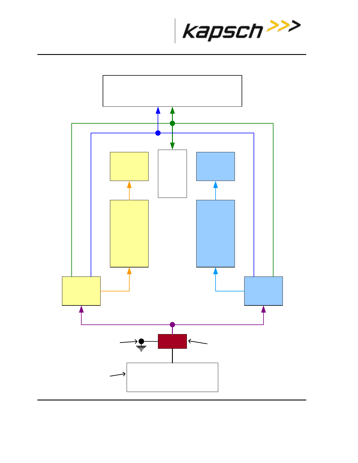
_
JANUS® Multi-Protocol Reader Ver. 2: Maintenance Instructions
Confidential UM 360463-202: A12 (Draft) Page 136 of 291
© Kapsch TrafficCom Canada Inc. 2013
These drawings and specifications contain confidential and proprietary information and are the property of Kapsch TrafficCom Canada Inc. and are issued in strict
confidence and will be kept confidential and used solely for the purpose intended and for no other purpose and shall not be transmitted, reproduced, copied, and/or
used as the basis for manufacture or sale of apparatus unless otherwise agreed to in writing by Kapsch TrafficCom Canada Inc.
FILE: MPR2_OPERATIONS_AND_MAINTENANCE-MANUAL_REV A12.DOCX 05/08/2014 11:24
Kapsch TrafficCom
Figure 4-1: Reader Power distribution
MRFM-S modules (1 to 8)
SPM
Secondary
CFM
Primary
CFM
Secondary
CTM
Primary
CTM
Secondary
PSM (left)
Primary
PSM (right)
Power Mains
110 VAC
nominal
+15 VDC/13.3A +5 VDC/10.0A
+3.3 VDC +3.3 VDC
+5 VDC/5A Secondary +5 VDC/5A Primary
Lightning/surge
suppressor
Power Mains
connection supplied
by system integrator
Earth ground system
supplied by system
integrator

_
JANUS® Multi-Protocol Reader Ver. 2: Maintenance Instructions
Confidential UM 360463-202: A12 (Draft) Page 137 of 291
© Kapsch TrafficCom Canada Inc. 2013
These drawings and specifications contain confidential and proprietary information and are the property of Kapsch TrafficCom Canada Inc. and are issued in strict
confidence and will be kept confidential and used solely for the purpose intended and for no other purpose and shall not be transmitted, reproduced, copied, and/or
used as the basis for manufacture or sale of apparatus unless otherwise agreed to in writing by Kapsch TrafficCom Canada Inc.
FILE: MPR2_OPERATIONS_AND_MAINTENANCE-MANUAL_REV A12.DOCX 05/08/2014 11:24
Kapsch TrafficCom
Lane Controller Port Module (LPM)
The LPM provides the serial communications connections between the CTM and the LC. The LC serial
communication signals travel to/from the CTM CGC board via the Distribution Module (DSM) to the
LPM serial port connectors. The LPM provides the 8 serial port connectors and integrated lighting
protection. The LPM is field replaceable.
The JANUS® Multi-Protocol Reader Ver. 2 is factory configured to support either an RS-232 or RS-422
interface. The data rate is configurable to standard rates up to 115.2 kbps.
Normally, each MRFM-S channel is assigned a unique LPM COM port; however, the MRFM-S
channels can be multiplexed by assigning multiple RF channels to one LC serial port, as necessary.
For a description of the serial interface protocol and file formats exchanged between a Lane Controller
and a Reader, refer to ICD 360450-111.
Sync Port Module (SPM)
The SPM provides a pathway for synchronization signals to and from both primary and secondary CTM
MC boards via the DSM to the SPM 6-terminal block connector where the synchronization STAR
network cables connect. The SPM is field replaceable.
A 4-Wire RS422 electrical connection at the front panel terminal block connects the SPM to the
synchronization network.
There are no active components installed on the SPM.
A three-position toggle switch mounted on the SPM provides Auto, Primary and Secondary redundancy
mode control signals via the DSM to the CTM.
Controller Module (CTM)
The CTM performs the Reader’s digital signal processing for OBUs. The CTMs may be swapped
without having to save the configuration file since the configuration data is stored in the CFMs mounted
on the DSM.
The CTM as a whole unit is field replaceable.
Main Controller (MC)
The MC is an off-the-shelf EBX form-factor industrial single-board computer. This unit contains the
CPU, memory and I/Os and is used to run the Reader software.
The MC receives OBU information from its associated CGC2 and performs a lane assignment for each
tag passing through the system via voting logic. It communicates with the LCs to report tag
transactions, accepts configuration messages, and provides status messages via a legacy LC serial
interface and/or an LC Ethernet interface. It detects and reports faults and can perform a switchover. It
offers Reader configuration via a browser interface, storage for transaction buffering, event logging,
and tag transaction and performance monitoring. It also supports remote software downloads. It
provides Inter-Reader communications with up to two other Readers, saves Reader configuration

_
JANUS® Multi-Protocol Reader Ver. 2: Maintenance Instructions
Confidential UM 360463-202: A12 (Draft) Page 138 of 291
© Kapsch TrafficCom Canada Inc. 2013
These drawings and specifications contain confidential and proprietary information and are the property of Kapsch TrafficCom Canada Inc. and are issued in strict
confidence and will be kept confidential and used solely for the purpose intended and for no other purpose and shall not be transmitted, reproduced, copied, and/or
used as the basis for manufacture or sale of apparatus unless otherwise agreed to in writing by Kapsch TrafficCom Canada Inc.
FILE: MPR2_OPERATIONS_AND_MAINTENANCE-MANUAL_REV A12.DOCX 05/08/2014 11:24
Kapsch TrafficCom
parameters to the primary and secondary CFM, manages the OBU Account Status file, and keeps log
files for OBU transactions, system events, and trouble reports.
For a description of the ethernet interface protocol and file formats exchanged between a Lane
Controller and a Reader, refer to ICD 360450-112.
Channel Group Controller Module (CGC2)
The CGC2 is used as a scheduler and a controller. It schedules when the MRFM-S operates and
routes the data from the MRFM-S to the MC.
Configuration Module (CFM)
The CFM is a field replaceable PWA board. These non-volatile memory cards store the Reader
configuration file. They are field-replaceable without using any tools.
Distribution Module (DSM)
The DSM back plane provides interconnections between the plug-in modules in the Reader rack. It is
not field-replaceable.
The DSM is responsible for the following.
Provides locations for all plug-in Reader modules and the Lane Kit RF modules
Distributes DC power from the PSMs to the necessary modules in the Reader rack
Carries RF data and control signals between primary and secondary CTMs and all MRFM-Ss
Carries synchronization and redundancy mode signals between primary and secondary CTMs and
the SPM
Carries data between primary and secondary CTMs and primary and secondary CFMs
Carries data between primary and secondary CTMs and primary and secondary LPMs
Synchronization
CAUTION:
On one redundant reader of a synchronization network, the
synchronization connection should be looped back and this reader
will declare sync even if it is disconnected from the other readers.
Readers must be synchronized if they have overlapping capture zones, are connected in an IR
network, or if Reader-to-Reader RF interference is present.

_
JANUS® Multi-Protocol Reader Ver. 2: Maintenance Instructions
Confidential UM 360463-202: A12 (Draft) Page 139 of 291
© Kapsch TrafficCom Canada Inc. 2013
These drawings and specifications contain confidential and proprietary information and are the property of Kapsch TrafficCom Canada Inc. and are issued in strict
confidence and will be kept confidential and used solely for the purpose intended and for no other purpose and shall not be transmitted, reproduced, copied, and/or
used as the basis for manufacture or sale of apparatus unless otherwise agreed to in writing by Kapsch TrafficCom Canada Inc.
FILE: MPR2_OPERATIONS_AND_MAINTENANCE-MANUAL_REV A12.DOCX 05/08/2014 11:24
Kapsch TrafficCom
If unsynchronized Readers are located within a 200 meter (660 feet) radius, tests for in-band RF
interference should be carried out to ensure that no Reader-to-Reader interference occurs. This test
should be carried out under live traffic conditions to ensure that RF signal reflections off moving
vehicles do not exceed the in-band limits. If Reader-to-Reader RF interference exceeds the in-band
limits then the Readers must be synchronized.
How Reader synchronization operates at the toll location
After interrogating all of the assigned MRFM-S slots in the rack, each Reader will provide a ‘sync
ready’ signal on its SPM terminal block. Only when the configuration parameter Enable Reader Sync
is set ON for all Readers in the sync network does synchronization occur.
As busy Readers become ready they will not send any more RF trigger signals until the sync bus
indicates that all Readers are ready. Once the last Reader in the network generates its ready signal, all
Readers on the sync bus simultaneously generate OBU trigger pulses starting with the RF module in
slot 1. This can be seen in the truth table shown below for synchronization circuit consisting of two
Readers.
Table 4-2: Boolean Logic Truth Table for Synchronization of two Readers
The truth table above demonstrates the following rule of synchronization operation:
The sync bus will only be in the ready state when all Readers in the group are in the ready state.
The last Reader to acquire a ready state controls the system synchronization. Most of the time (greater
than 95%), the sync bus will be in the busy state. If operating correctly, the sync bus will normally be in
the ready state for about 100 Sec.
The Sync Recovery Process
When a Reader detects it is out of synchronization, it attempts to re-establish synchronization at the
beginning of every superframe. During this time, the CTM SYNC LED flashes green/orange (the orange
is a mix of green and red due to the short amount of time in red).
Note: Connection of other equipment or external synchronization devices is not supported and may
cause Reader errors.
Reader 1 sync port Tx
Reader 2 sync port Tx
Reader 1 or 2 sync port Rx
0 (ready)
0 (ready)
0 (ready)
0 (ready)
1 (busy)
1 (busy)
1 (busy)
0 (ready)
1 (busy)
1 (busy)
1 (busy)
1 (busy)

_
JANUS® Multi-Protocol Reader Ver. 2: Maintenance Instructions
Confidential UM 360463-202: A12 (Draft) Page 140 of 291
© Kapsch TrafficCom Canada Inc. 2013
These drawings and specifications contain confidential and proprietary information and are the property of Kapsch TrafficCom Canada Inc. and are issued in strict
confidence and will be kept confidential and used solely for the purpose intended and for no other purpose and shall not be transmitted, reproduced, copied, and/or
used as the basis for manufacture or sale of apparatus unless otherwise agreed to in writing by Kapsch TrafficCom Canada Inc.
FILE: MPR2_OPERATIONS_AND_MAINTENANCE-MANUAL_REV A12.DOCX 05/08/2014 11:24
Kapsch TrafficCom
Log files
The log files for OBU transactions are saved on the CFM. Once space is filled on the respective
memory partition, the oldest file from the same file type is deleted to create memory space for the new
data.
A listing of the main log file types appears below. Other log files that may be present are for Kapsch
TrafficCom use only.
Table 4-3: List of Available Log Files
Log File Type
Description
tagtxns_yyyy-mm-dd
Daily tag Transaction log.
eventlog_yyyy-mm-dd
Daily event log files. Event log contain a periodic report of system
health and transaction count totals.
trouble_yyyy-mm-dd
Trouble Log. Content lists any unusual system anomaly (e.g.
switchover).
Transaction logs
CAUTION:
Log file formats are not under ICD control and the format may
change without prior notification. Log files are for diagnostic
purposes only and are not guaranteed to be maintained in non-
volatile storage.
Each transaction generates a two-line report containing the fields described in the table below.
Table 4-4: List of Fields in a Transaction Log Report
Field
Description
IREAD
Optional initial read report when transponder first enters capture zone. Informational report
VOTE
Transaction report at voting time
POST
Optional post-capture zone report if lane assignment or programming status has changed.
Informational report
An
Antenna number (present only if in interpolated lane assignment mode)

_
JANUS® Multi-Protocol Reader Ver. 2: Maintenance Instructions
Confidential UM 360463-202: A12 (Draft) Page 141 of 291
© Kapsch TrafficCom Canada Inc. 2013
These drawings and specifications contain confidential and proprietary information and are the property of Kapsch TrafficCom Canada Inc. and are issued in strict
confidence and will be kept confidential and used solely for the purpose intended and for no other purpose and shall not be transmitted, reproduced, copied, and/or
used as the basis for manufacture or sale of apparatus unless otherwise agreed to in writing by Kapsch TrafficCom Canada Inc.
FILE: MPR2_OPERATIONS_AND_MAINTENANCE-MANUAL_REV A12.DOCX 05/08/2014 11:24
Kapsch TrafficCom
Field
Description
Master
Set
The set of three (3) inter-Reader channels that have the most tag reads (C = center Reader, L = left
Reader, R = right Reader). (present only if in interpolated lane assignment mode)
Zone
Sub-zone information (a – f). (Present only if in interpolated lane assignment mode)
Ch
Channel number. Indicates the assigned channel (1-8). Channel 1 corresponds to the leftmost RF
module in the RF rack.
St
Transaction status.
Pgm indicates successful transponder programming.
PU indicates transponder programming status is Unknown (tag left zone before verify could
complete).
PF indicates transponder was not programmed successfully.
Read indicates the Reader is in read only mode.
CrossR indicates an informational report (not a transaction).
Txn
Transaction number. Note that transaction numbers may appear to skip when using 2 or more
Readers with Ethernet connection between them.
Ag
Agency ID of transponder in capture zone.
Sn
Serial number of transponder in capture zone.
Ahs
Number of handshakes up to voting time.
THs
Total Handshakes for previous transaction assigned to this channel.
GUARD
Shown for a transaction assigned to a RF channel set to Guard. These transactions will show !LC
to indicate that no report for the LC is generated. Tag programming is disabled for Guard channels.
?LA
In a POST report, indicates that a lane assignment change was detected between the voting time
report and the post time report. May be an indication that voting time is not optimal.
?PS
In a POST report, indicates that a programming status change was detected between the voting
time report and the post time report.
>LC
>LC indicates transaction is to be reported to lane controller (connection present or not). Only
appears on the Active CTM
!LC
!LC indicates transaction is suppressed (e.g. GUARD lane or CrossR transactions or CTM is
Inactive).
Cx-HS
HS tag handshakes seen up to voting/post time on the MasterSet center Reader.
Lx-HS
HS tag handshakes seen up to voting/post time on the MasterSet left Reader.
Rx-HS
HS tag handshakes seen up to voting/post time on the MasterSet right Reader.
Transaction Buffering
Transactions from OBUs, are processed by the CTM. When a Reader CTM loses communications
with an Lane Controller (LC), the Reader buffers OBU transactions and error messages (up to a
combined total of 400,000) in non-volatile memory (i.e. buffered messages will not be lost during power

_
JANUS® Multi-Protocol Reader Ver. 2: Maintenance Instructions
Confidential UM 360463-202: A12 (Draft) Page 142 of 291
© Kapsch TrafficCom Canada Inc. 2013
These drawings and specifications contain confidential and proprietary information and are the property of Kapsch TrafficCom Canada Inc. and are issued in strict
confidence and will be kept confidential and used solely for the purpose intended and for no other purpose and shall not be transmitted, reproduced, copied, and/or
used as the basis for manufacture or sale of apparatus unless otherwise agreed to in writing by Kapsch TrafficCom Canada Inc.
FILE: MPR2_OPERATIONS_AND_MAINTENANCE-MANUAL_REV A12.DOCX 05/08/2014 11:24
Kapsch TrafficCom
interruptions or Reader resets). When the memory is full, new transactions overwrite the oldest
buffered transactions. The memory available for buffering is shared by all RF channels.
When the communication link between an LC and the Reader is re-established, the Reader begins to
upload the buffered transactions to the LC. The Reader will pause uploading buffered transactions to
the LC to report any new transactions as they occur. Buffered transaction reporting resumes after the
new transactions have been reported. Messages from the LC will continue to be acknowledged and
acted upon during the upload process.
Event Logs
The event log is generated to record any reader events or changes (for example, if the power supply
status changes). During service, the technician should first examine the event log files to see if there
are any reported events with the reader.
The following list depicts the possible sources of event messages found in the event log.
Changes to the reader configuration
Changes to the reader configuration at power up
Reader status changes, such as PSM status, etc.
Reader faults detected

_
JANUS® Multi-Protocol Reader Ver. 2: Maintenance Instructions
Confidential UM 360463-202: A12 (Draft) Page 143 of 291
© Kapsch TrafficCom Canada Inc. 2013
These drawings and specifications contain confidential and proprietary information and are the property of Kapsch TrafficCom Canada Inc. and are issued in strict
confidence and will be kept confidential and used solely for the purpose intended and for no other purpose and shall not be transmitted, reproduced, copied, and/or
used as the basis for manufacture or sale of apparatus unless otherwise agreed to in writing by Kapsch TrafficCom Canada Inc.
FILE: MPR2_OPERATIONS_AND_MAINTENANCE-MANUAL_REV A12.DOCX 05/08/2014 11:24
Kapsch TrafficCom
Trouble Logs
Unusual Reader issues generate trouble logs (for example, if a switchover has occurred). During
service, the technician should first examine these trouble log files to see if there are any reported
issues with the Reader.
Examine the Log Files page for instances of one or more trouble <date> file in the list of log files.
A typical report in a trouble log is:
2010-05-31T10:52:35.723+00:00 [lab3_5] SYNCR: Reader SYNC lost
Note: As an alternative, Kapsch Service can remotely connect to the Reader and examine the trouble
log to quickly identify and resolve any issues. It is up to the system administrator or integrator to
determine when to grant Kapsch Service remote access to the LC network IP addresses.
The following list depicts the possible sources of trouble messages found in the trouble <date> file.
No detection of a CFM backplane memory module.
The Status file integrity check fails. Possible cause: there may be data for up to 40 million OBUs in a
Status file.
The Reader software forced a switchover on detection of:
o Failed CGC health
o Failed serial LC link (when enabled). Possible cause: a fault external to the Reader
o Failed Ethernet LC link (when enabled). Possible cause: a fault external to the Reader
o Failed Ethernet inter-Reader link (when enabled). Possible cause: a fault external to the Reader
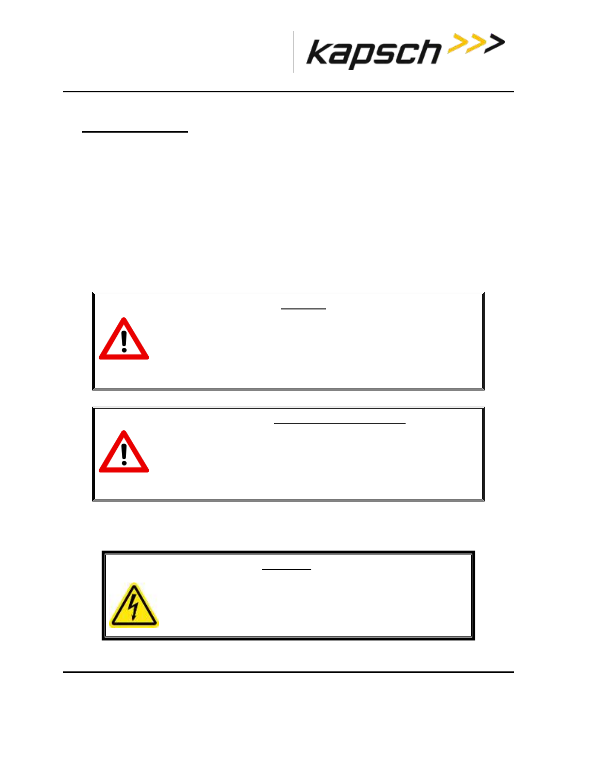
_
JANUS® Multi-Protocol Reader Ver. 2: Maintenance Instructions
Confidential UM 360463-202: A12 (Draft) Page 144 of 291
© Kapsch TrafficCom Canada Inc. 2013
These drawings and specifications contain confidential and proprietary information and are the property of Kapsch TrafficCom Canada Inc. and are issued in strict
confidence and will be kept confidential and used solely for the purpose intended and for no other purpose and shall not be transmitted, reproduced, copied, and/or
used as the basis for manufacture or sale of apparatus unless otherwise agreed to in writing by Kapsch TrafficCom Canada Inc.
FILE: MPR2_OPERATIONS_AND_MAINTENANCE-MANUAL_REV A12.DOCX 05/08/2014 11:24
Kapsch TrafficCom
5. INSTALLATION
Introduction
The Reader is shipped with the required power, communications, and logic modules. The Lane Kits,
separate from the Reader, each consist of an antenna, an MRFM-S, and a feedline cable adapter.
After the equipment is installed, the Reader must be configured via the browser interface. After
configuration is complete, the Reader configuration should be saved (see Saving the Reader
configuration, page 243) for future reference.
The toll agency and/or system integrator must select the configuration and setup that is suitable for the
application and the desired system performance.
CAUTION:
Improper modification of configuration parameters may adversely
affect system operation. The default values may not be appropriate
for the specific application. It is the system integrator’s responsibility
to tailor the configuration parameters to the specific operating
environment.
CAUTION: Redundant Reader
Configure both CTMs in a redundant Reader. Each CTM has its own
browser interface and is configured independently. Ensure any
configuration changes made to one CTM are applied to the other CTM,
as required.
The earth ground system
WARNING:
AN IMPROPERLY GROUNDED READER COULD RESULT IN ELECTRIC
SHOCK. ENSURE A HIGH CURRENT EARTH GROUND CONNECTION
IS ESTABLISHED BEFORE CONNECTING SUPPLY POWER.
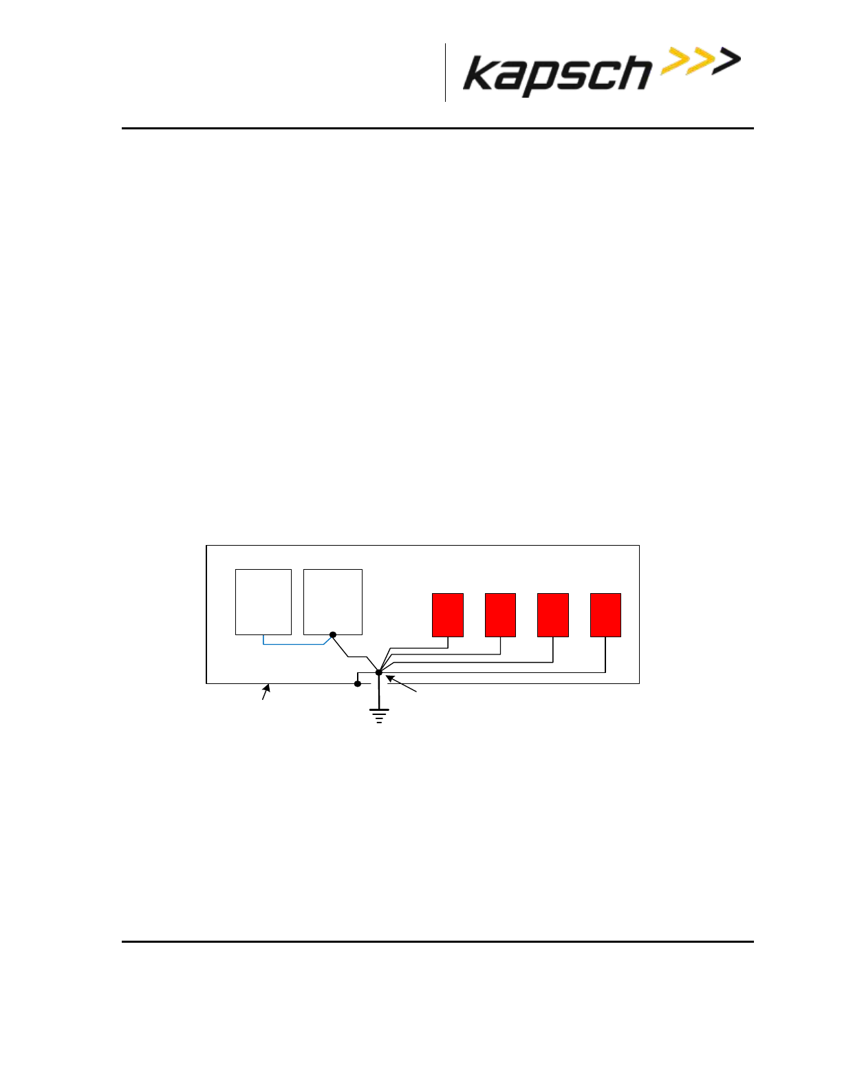
_
JANUS® Multi-Protocol Reader Ver. 2: Maintenance Instructions
Confidential UM 360463-202: A12 (Draft) Page 145 of 291
© Kapsch TrafficCom Canada Inc. 2013
These drawings and specifications contain confidential and proprietary information and are the property of Kapsch TrafficCom Canada Inc. and are issued in strict
confidence and will be kept confidential and used solely for the purpose intended and for no other purpose and shall not be transmitted, reproduced, copied, and/or
used as the basis for manufacture or sale of apparatus unless otherwise agreed to in writing by Kapsch TrafficCom Canada Inc.
FILE: MPR2_OPERATIONS_AND_MAINTENANCE-MANUAL_REV A12.DOCX 05/08/2014 11:24
Kapsch TrafficCom
The system integrator supplies the earth ground system for the Reader mains power as per the IEEE
142-2007 standard, particularly; chapter 5: Sensitive Electronic Equipment Grounding; and chapter 3
pertaining to lightning protection; and all other chapter sections describing bonding applications.
The system integrator is responsible for ensuring the grounding and power conforms to local regulatory
and safety requirements. The recommendations herein are those to ensure bad grounding does not
degrade the reader performance.
In accordance with IEEE 142-2007 all of the following building/site elements (if available) must be
bonded together:
metal frame of the building (if effectively grounded)
metal underground water pipe
ground ring, concrete encased electrode
The Reader ground bar (supplied by the system integrator) is bonded to the above-mentioned
elements. If none of these elements are available on site, only then a grounding electrode is installed
as per NEC to which the Reader ground bar is bonded. The Reader components ground wires are then
connected to the ground bar clamps as shown in Figure 5-1.
Lightning arrestors should be installed on the interfaces where lightning induced surges can occur.
Note: The toll plaza installation may not have a NEMA 4 enclosure. The earth ground system and all
other ground connections to Reader components at the toll plaza are identical to those shown in the
figure below.
Figure 5-1: Earth Ground System (with recommended lightning protectors shown)
Lightning protectors
Note: It is the system integrator’s responsibility to determine the necessity of installing lightning/surge
protection equipment between the data inputs and the earth ground system at the Lane Controller (LC).
EIA 19 in.
rack
Ground bar and clamp(s) are bonded to building/site
elements (if available) as per IEEE 142-2007, otherwise
the ground bar and clamp(s) are bonded to a grounding
electrode installed as per NEC.
AC Mains
(to PSMs and
ESMs)
AWG 10
AWG 8
Reader
Chassis
ground strap braid wire
RF
feedline
Lightning Protectors
LC data
cables Sync
circuit
Reader enclosure
(NEMA 4)

_
JANUS® Multi-Protocol Reader Ver. 2: Maintenance Instructions
Confidential UM 360463-202: A12 (Draft) Page 146 of 291
© Kapsch TrafficCom Canada Inc. 2013
These drawings and specifications contain confidential and proprietary information and are the property of Kapsch TrafficCom Canada Inc. and are issued in strict
confidence and will be kept confidential and used solely for the purpose intended and for no other purpose and shall not be transmitted, reproduced, copied, and/or
used as the basis for manufacture or sale of apparatus unless otherwise agreed to in writing by Kapsch TrafficCom Canada Inc.
FILE: MPR2_OPERATIONS_AND_MAINTENANCE-MANUAL_REV A12.DOCX 05/08/2014 11:24
Kapsch TrafficCom
Table 5-1: Locations for the Installation of Lightning Protectors
Location required
Schematic Figure number
In-line with antenna RF feed
Figure 5-1: Earth Ground System (with recommended lightning protectors
shown), page 145
PSM power
Figure 5-2 AC Mains, page 147
LC Data inputs
Figure 5-3: LC Data Cable Installation, page 148
ESM power
Figure 5-10: Schematic of a three-Reader IR network, page 165
Synchronization circuit
Figure 5-9: Synchronization circuit schematic for three Readers, page 159
Installing the Reader hardware
Prerequisites: The Reader cabinet is commissioned and the earth ground system has been installed
as per IEEE 142-2007 (see The earth ground system on page 144).
Install the AC receptacle for the Reader mains power connections within three (3) feet of the front of
the Reader.
Note: When handling Reader modules and hardware, always follow accepted Electrostatic Discharge
(ESD) practices and standards.
1. Using clip nuts, mount the Reader in the EIA 19-inch rack in a NEMA 4 cabinet.
2. Connect the EIA 19-inch rack ground lug to earth ground:
3. Connect one end of a braided ground strap to the ground lug on the EIA 19-inch rack.
4. Neatly position the ground strap along the Reader and apply a light film of tuner lube to the ground lug on
the rear of the Reader rack to ensure good grounding contact.
5. Secure the other end of the braided ground strap to the Reader ground lug.
CAUTION:
To avoid damaging the modules, ensure that alignment of both
the connector on the module and the connector on the DSM
(back plane) is correct before securely plugging the module into
the DSM.
6. Install the Reader modules in the Reader, ensuring the modules seat properly in their sockets. The
installation of the MRFM-S is outlined in Installing a Lane Kit on page 149.
7. Install the power cords for the primary and secondary PSMs. Appropriate lightning/surge protection
equipment should be installed between the power mains input and the earth ground system at the Reader
(see Figure 5-2 on page 147).
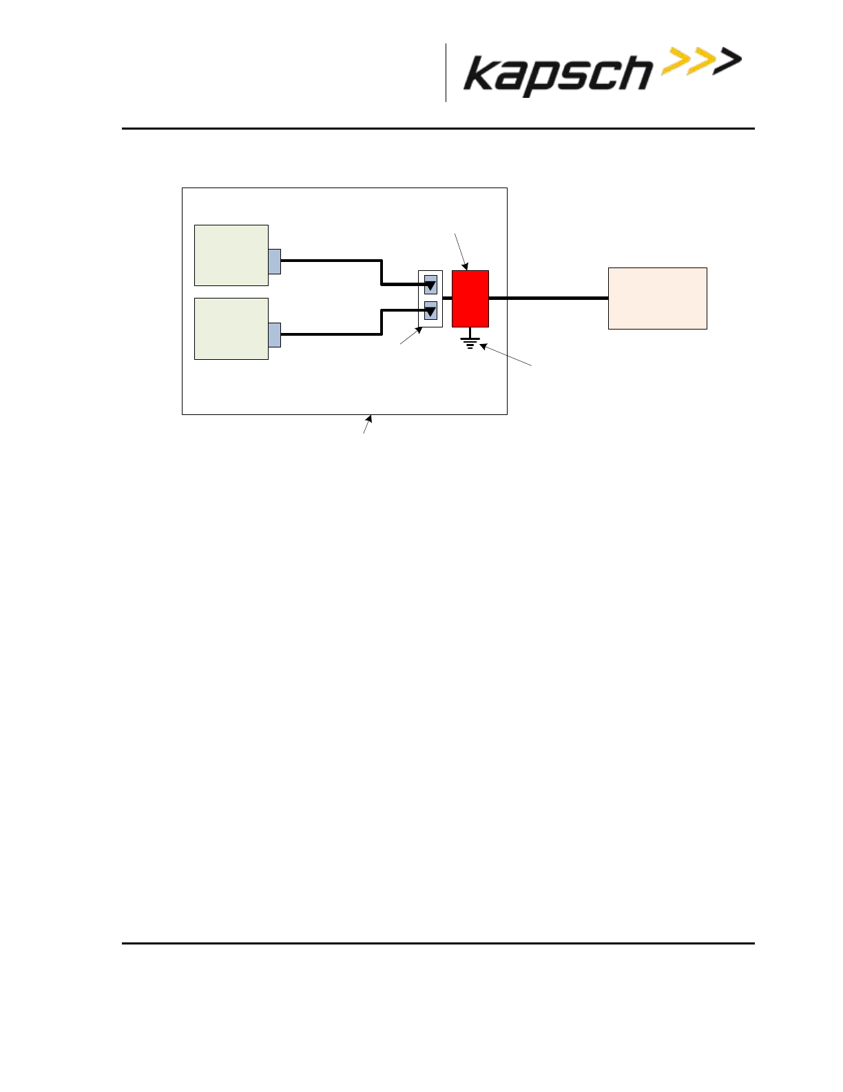
_
JANUS® Multi-Protocol Reader Ver. 2: Maintenance Instructions
Confidential UM 360463-202: A12 (Draft) Page 147 of 291
© Kapsch TrafficCom Canada Inc. 2013
These drawings and specifications contain confidential and proprietary information and are the property of Kapsch TrafficCom Canada Inc. and are issued in strict
confidence and will be kept confidential and used solely for the purpose intended and for no other purpose and shall not be transmitted, reproduced, copied, and/or
used as the basis for manufacture or sale of apparatus unless otherwise agreed to in writing by Kapsch TrafficCom Canada Inc.
FILE: MPR2_OPERATIONS_AND_MAINTENANCE-MANUAL_REV A12.DOCX 05/08/2014 11:24
Kapsch TrafficCom
Figure 5-2 AC Mains
6 ft. power cord
PSM
primary
Reader enclosure
PSM
secondary
POWER
MAINS
6 ft. power cord
duplex receptacle
supplied by system
integrator
Power mains and
cable to Reader
enclosure supplied by
system integrator
lightning surge
suppressor supplied
by system integrator
Earth ground system as per
“NEC grounding electrode”
MPR2
Connect the appropriate cables from the Reader to the LC as shown in Figure 5-3 on page 148.
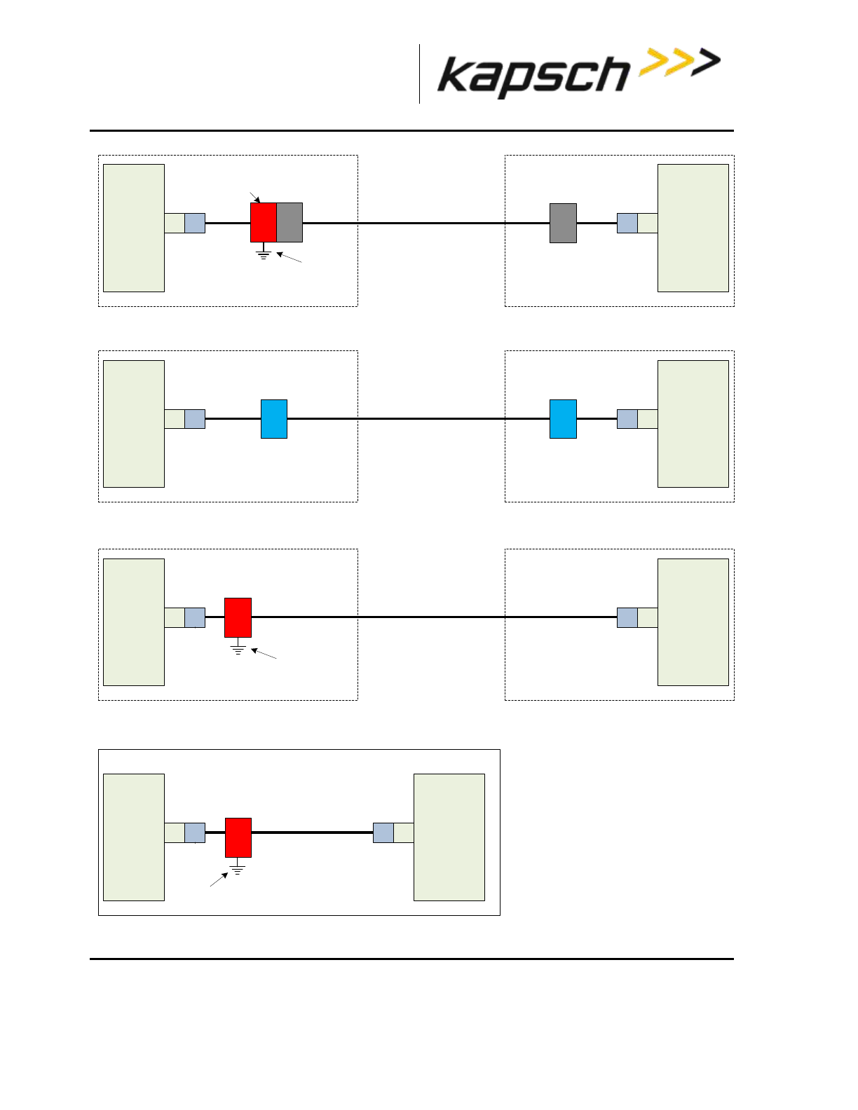
_
JANUS® Multi-Protocol Reader Ver. 2: Maintenance Instructions
Confidential UM 360463-202: A12 (Draft) Page 148 of 291
© Kapsch TrafficCom Canada Inc. 2013
These drawings and specifications contain confidential and proprietary information and are the property of Kapsch TrafficCom Canada Inc. and are issued in strict
confidence and will be kept confidential and used solely for the purpose intended and for no other purpose and shall not be transmitted, reproduced, copied, and/or
used as the basis for manufacture or sale of apparatus unless otherwise agreed to in writing by Kapsch TrafficCom Canada Inc.
FILE: MPR2_OPERATIONS_AND_MAINTENANCE-MANUAL_REV A12.DOCX 05/08/2014 11:24
Kapsch TrafficCom
Figure 5-3: LC Data Cable Installation
LC data cable installation – ETHERNET 1 port, patch cable to solid conductor
8P8C
(RJ45)
CTM LANE
CONTROLLER
Reader enclosure
lightning protector
CAT6 – 8 conductor, 24 AWG
LC data cable installation from LPM – RS422
DB9
LPM LANE
CONTROLLER
Reader enclosure
LC data cable installation from LPM – RS232
DB9
LPM LANE
CONTROLLER
Roadside Equipment LANE CONTROLLER
lightning protector
Maximum run limited by baud
rate, typically:
less than 50 feet at 9.6 Kb/s
Maximum run without a repeater
is limited by baud rate, typically:
less than 4000 ft at 19.2 Kb/s
less than 1700 ft at 115.2 Kb/s
Maximum run without a router,
hub or repeater is limited by
baud rate, typically:
less than 333 feet at 1 Gb/s
This consists of 300 ft of 24
AWG solid "horizontal" cabling
between the jacks at each end,
plus not more than 33 ft of 24
AWG stranded patch cable
between each jack and the
CTM.
*2 pair twisted
*2 pair twisted
TOLL PLAZA
* 2 pair twisted cable specified in the EIA RS232C,
CCITT V.55 and RS422 interface standards:
Conductor size and type: 24 AWG, twisted pair.
Nominal capacitance: 15.5 picofarads per foot
(between conductors of each pair); 27.5 picofarads
per foot (from each conductor to shield).
Nominal DC resistance (each conductor): 24.0
ohms per 1000 feet.
Nominal DC resistance (shield): 2.35 ohms per
1000 feet.
Shield type: Overall braided with drain wire.
Approval: Underwriters Laboratories (UL).
lightning protector
LC data cable installation – ETHERNET 1 port, patch cable to fiber optic
8P8C
(RJ45)
CTM LANE
CONTROLLER
Reader enclosure
fiber optic system
supplied by system
integrator
CAT6 – 8 conductor, 24 AWG
stranded patch cable
plus fiber optic
(fiber optic length dependant on
type chosen, typically 5000 ft)
and not more than 33 ft of 24
AWG stranded patch cable
between the fiber optic coupler
and the CTM.
jack
jack
patch patch
patch patch
fiber optic
coupler fiber optic
coupler
Earth ground system
Earth ground system
Earth ground system

_
JANUS® Multi-Protocol Reader Ver. 2: Maintenance Instructions
Confidential UM 360463-202: A12 (Draft) Page 149 of 291
© Kapsch TrafficCom Canada Inc. 2013
These drawings and specifications contain confidential and proprietary information and are the property of Kapsch TrafficCom Canada Inc. and are issued in strict
confidence and will be kept confidential and used solely for the purpose intended and for no other purpose and shall not be transmitted, reproduced, copied, and/or
used as the basis for manufacture or sale of apparatus unless otherwise agreed to in writing by Kapsch TrafficCom Canada Inc.
FILE: MPR2_OPERATIONS_AND_MAINTENANCE-MANUAL_REV A12.DOCX 05/08/2014 11:24
Kapsch TrafficCom
Installing a Lane Kit
Installing an Antenna
1. The antenna mounts on a frame using 2-inch diameter galvanized pipe clamps. Position the center
antenna at lane center of the defined lane. For wide ORT applications, the straddle antenna must be at
the midpoint between the left and right antennas. Orient the weep holes down, such that the radome is
facing oncoming traffic.
2. Using a tilt meter, measure the road pitch and cross lane slope directly under each IAG antenna. Record
the results.
3. Using a tilt meter, align each antenna plate to the tilt angle specified in Table 5-2, in relation to the road
pitch measured in step 2 (e.g., If the road pitch is 2 degrees. and the antenna tilt must be 15 degrees,
mount the antenna at 17 degrees.)
4. Ensure that the height of the antenna’s lower edge as tilted falls within the height range given Table 5-2.
Please contact Kapsch Service when considering mounting the antennas outside the specified heights.
5. Adjust the roll angle of the antenna equal to 0 degrees with respect to the cross lane slope obtained in
step 2.
6. For TDM only protocol, the antenna installation may be all antennas (IAG 1 or IAG 2 or IAG 3) inline
across the roadway as shown in Figure 5-3
7. For TDM protocol, and/or ISO18000-6C protocol (read only) only, the antenna installation may be all
antennas IAG 3 only) inline across the roadway as shown in Figure 5-3.
8. For all passive protocols (other than ISO18000-6C read only) the antenna installation must be all
antennas (IAG 3 only) staggered across the roadway as shown in Figure 5-3.
Table 5-2 Antenna mounting for the IAG 3 antenna and lane configuration
Antenna
Application
Lane Width
Height
Tilt (off
horizontal)
IAG-3
ORT or Plaza
12 ft.
17 ft. ±1 ft.
10 deg.
IAG-1
ORT or Plaza
12 ft.
16 ft. ±1 ft.
10 deg.
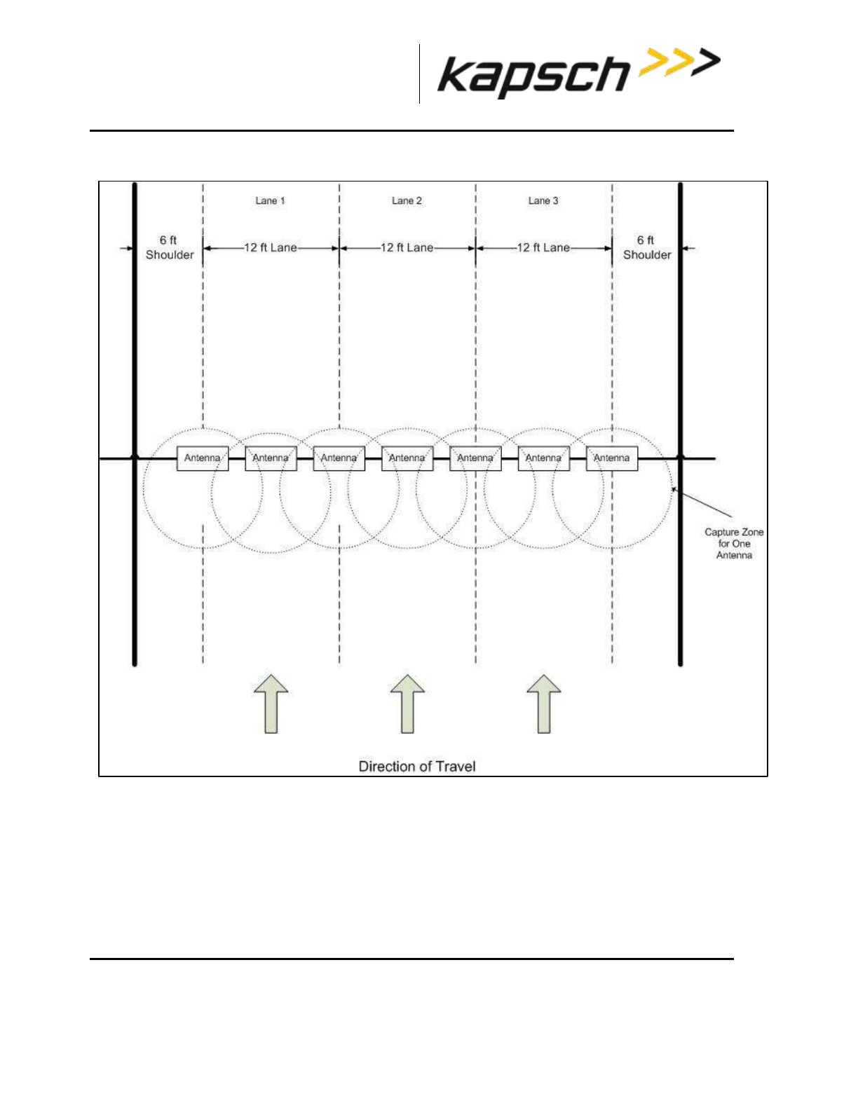
_
JANUS® Multi-Protocol Reader Ver. 2: Maintenance Instructions
Confidential UM 360463-202: A12 (Draft) Page 150 of 291
© Kapsch TrafficCom Canada Inc. 2013
These drawings and specifications contain confidential and proprietary information and are the property of Kapsch TrafficCom Canada Inc. and are issued in strict
confidence and will be kept confidential and used solely for the purpose intended and for no other purpose and shall not be transmitted, reproduced, copied, and/or
used as the basis for manufacture or sale of apparatus unless otherwise agreed to in writing by Kapsch TrafficCom Canada Inc.
FILE: MPR2_OPERATIONS_AND_MAINTENANCE-MANUAL_REV A12.DOCX 05/08/2014 11:24
Kapsch TrafficCom
Figure 5-4 Inline Antenna Installation
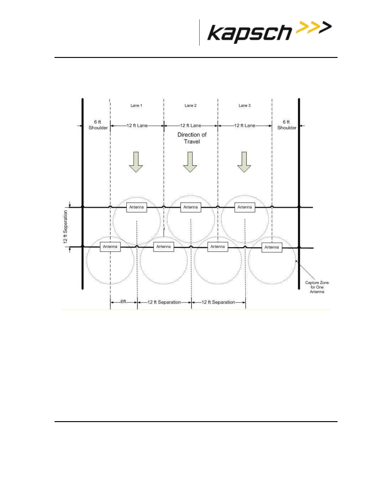
_
JANUS® Multi-Protocol Reader Ver. 2: Maintenance Instructions
Confidential UM 360463-202: A12 (Draft) Page 151 of 291
© Kapsch TrafficCom Canada Inc. 2013
These drawings and specifications contain confidential and proprietary information and are the property of Kapsch TrafficCom Canada Inc. and are issued in strict
confidence and will be kept confidential and used solely for the purpose intended and for no other purpose and shall not be transmitted, reproduced, copied, and/or
used as the basis for manufacture or sale of apparatus unless otherwise agreed to in writing by Kapsch TrafficCom Canada Inc.
FILE: MPR2_OPERATIONS_AND_MAINTENANCE-MANUAL_REV A12.DOCX 05/08/2014 11:24
Kapsch TrafficCom
Figure 5-5 Staggered Antenna Installation
_
JANUS® Multi-Protocol Reader Ver. 2: Maintenance Instructions
Confidential UM 360463-202: A12 (Draft) Page 152 of 291
© Kapsch TrafficCom Canada Inc. 2013
These drawings and specifications contain confidential and proprietary information and are the property of Kapsch TrafficCom Canada Inc. and are issued in strict
confidence and will be kept confidential and used solely for the purpose intended and for no other purpose and shall not be transmitted, reproduced, copied, and/or
used as the basis for manufacture or sale of apparatus unless otherwise agreed to in writing by Kapsch TrafficCom Canada Inc.
FILE: MPR2_OPERATIONS_AND_MAINTENANCE-MANUAL_REV A12.DOCX 05/08/2014 11:24
Kapsch TrafficCom
The JANUS reader system and antennas in the lane kits are optimized for applications using 12 foot
lane widths. The antenna placement requirements and support for this and other lane widths are as
follows.
The lane centerline is the mid-point between the lane markings.
The antenna boresite should be on the lane centerline and lane markings.
Physical lane widths below 12 ft are not an issue provided the separation between lane centers
is 12 ft or greater.
o If separations are below this there is a higher risk of reports from multiple lanes for the
same tag. Note the use of the voting algorithms will correctly assign the tag to the
correct lane). There may also be some reduction in the read performance for passive
protocols.
If the physical lane width exceeds 15 ft, the lane should be treated as a multi-lane free flow
configuration and multiple lane kits used per lane.
Where multiple readers are on a site, the following additional guidelines apply:
The readers must be synchronized and running the same configuration.
The same FDM channel frequency should not be used on adjacent lanes (including straddle
and shoulder).
The same active channel from two (2) synchronized readers should not be used on adjacent
lanes (including straddle and shoulder).
Installing the MRFM-S Modules
CAUTION:
To avoid damaging the modules, ensure that alignment of both
the connector on the module and the connector on the DSM
(back plane) is correct before securely plugging the module into
the DSM.
1. Insert the required number of MRFM-S Modules into the Reader and secure in place.
2. Label the front panel of each MRFM-S Module with the corresponding lane number and antenna type.
Installing the RF cables
CAUTION:
Excessive bending or kinking can damage the RF feedline cables. Do not
excessively bend or kink the RF feedline cables while fishing them through
the rigid conduit from the antenna to the Reader enclosure.
1. Place the RF feedline cable(s) in position. Use an appropriate cable type (coaxial or Heliax) to ensure the
RF feedline cable does not produce a signal loss greater than permitted, see section 8 RF Cable

_
JANUS® Multi-Protocol Reader Ver. 2: Maintenance Instructions
Confidential UM 360463-202: A12 (Draft) Page 153 of 291
© Kapsch TrafficCom Canada Inc. 2013
These drawings and specifications contain confidential and proprietary information and are the property of Kapsch TrafficCom Canada Inc. and are issued in strict
confidence and will be kept confidential and used solely for the purpose intended and for no other purpose and shall not be transmitted, reproduced, copied, and/or
used as the basis for manufacture or sale of apparatus unless otherwise agreed to in writing by Kapsch TrafficCom Canada Inc.
FILE: MPR2_OPERATIONS_AND_MAINTENANCE-MANUAL_REV A12.DOCX 05/08/2014 11:24
Kapsch TrafficCom
Specification. Use flexible cable (LMR400 preferred) for the short feedline cable between the circulator
and the antenna
2. Using tie wraps, create a service loop of 6 feet at both ends of the RF feedline cable(s). Trim the excess
cable length.
3. Install spiral wraps on the RF feedline cable(s) where necessary to protect it from abrasion.
4. Using marker tie wraps and label sets, label the Reader end of each RF feedline (ex. TX Lane 1 or RX
Lane 1), each antenna RF feedline (ex. Tx lane 1 or Rx lane 1).
5. Attach the N-Type male connector to the antenna end of the RF feedline cable(s) . Firmly crimp the
male connector.
For Mono-Static Operation only
(Not Currently Supported). See Figure 5-3
1. Using a 10in-lb torque wrench, connect the RF feedline cable to the antenna. Using self-amalgamating
tape, wrap the connection to ensure water cannot enter.
2. Attach the N-Type female connector to the Reader end of the feedline cable . Firmly crimp the female
connector.
3. Using a 10in-lb torque wrench, connect the RF feedline from the antenna to the RF adapter cable
(800125-001).
Note: A lightning protector should be installed between the RF adapter cable and the feedline cable.
For Bi-Static Operation Only.
See Figure 5-3
1. Using a 10in-lb torque wrench, connect the first RF feedline cable to the Circulator (Port 1). Using self-
amalgamating tape, wrap the connection to ensure water cannot enter.
2. Using a 10in-lb torque wrench, connect the second RF feedline cable to the Circulator (Port 3). Using
self- amalgamating tape, wrap the connection to ensure water cannot enter.
3. Using a 10in-lb torque wrench, connect a third (3.0 foot long) RF feedline cable to the Circulator (Port 2).
Using self-amalgamating tape, wrap the connection to ensure water cannot enter.
4. Attach the N-Type male connector (322389-032) to the antenna end of the third (3.0 foot long) RF
feedline cable. Firmly crimp the male connector.
5. Using a 10in-lb torque wrench, connect the other end of the third (3.0 foot long) RF feedline cable that is
connected to Port 2 of the Circulator, to the antenna. Using self-amalgamating tape, wrap the connection
to ensure water cannot enter.
6. Attach the N-Type female connector to the reader end of the first RF feedline cable. Firmly crimp the
female connector.
7. Using a 10in-lb torque wrench, connect the other end of the first RF Feedline cable that is connected to
Port 1 of the Circulator, to the RF Adaptor Cable (800125-001), that will be connected to the “Antenna”
Port of the MRFMS.
8. Attach the N-Type female connector ) to the reader end of the second RF feedline cable. Firmly crimp
the female connector.
9. Using a 10in-lb torque wrench, connect the other end of the second RF Feedline cable that is connected
to Port 3 of the Circulator, to the RF Adaptor Cable (800125-001), that will be connected to the “RX” Port
of the MRFMS.

_
JANUS® Multi-Protocol Reader Ver. 2: Maintenance Instructions
Confidential UM 360463-202: A12 (Draft) Page 154 of 291
© Kapsch TrafficCom Canada Inc. 2013
These drawings and specifications contain confidential and proprietary information and are the property of Kapsch TrafficCom Canada Inc. and are issued in strict
confidence and will be kept confidential and used solely for the purpose intended and for no other purpose and shall not be transmitted, reproduced, copied, and/or
used as the basis for manufacture or sale of apparatus unless otherwise agreed to in writing by Kapsch TrafficCom Canada Inc.
FILE: MPR2_OPERATIONS_AND_MAINTENANCE-MANUAL_REV A12.DOCX 05/08/2014 11:24
Kapsch TrafficCom
10. Using an SMA wrench, connect each RF Adapter Cable(s) (800125-001) SMA connector to the assigned
MRFM-S module port(s).
11. Tie all RF Adapter cables neatly and label both ends of each adapter cable, using marker tie wraps from
the label set (800498-001).
12. Secure the service loop portion of the feedline to the antenna-mounting bracket using the tie wraps. Do
not severely bend or kink the RF feedline cable.
Note: For a TDM only protocol configuration (i.e., no passive protocols), the Circulator can be located in
the cabinet with the reader and one RF feedline cable is connected between port 2 of the Circulator and
the antenna. Ports 1 and 3 of the circulator are then connected to the RF modules using the RF Adaptor
Cables (800125-001); see Figure 5-3.
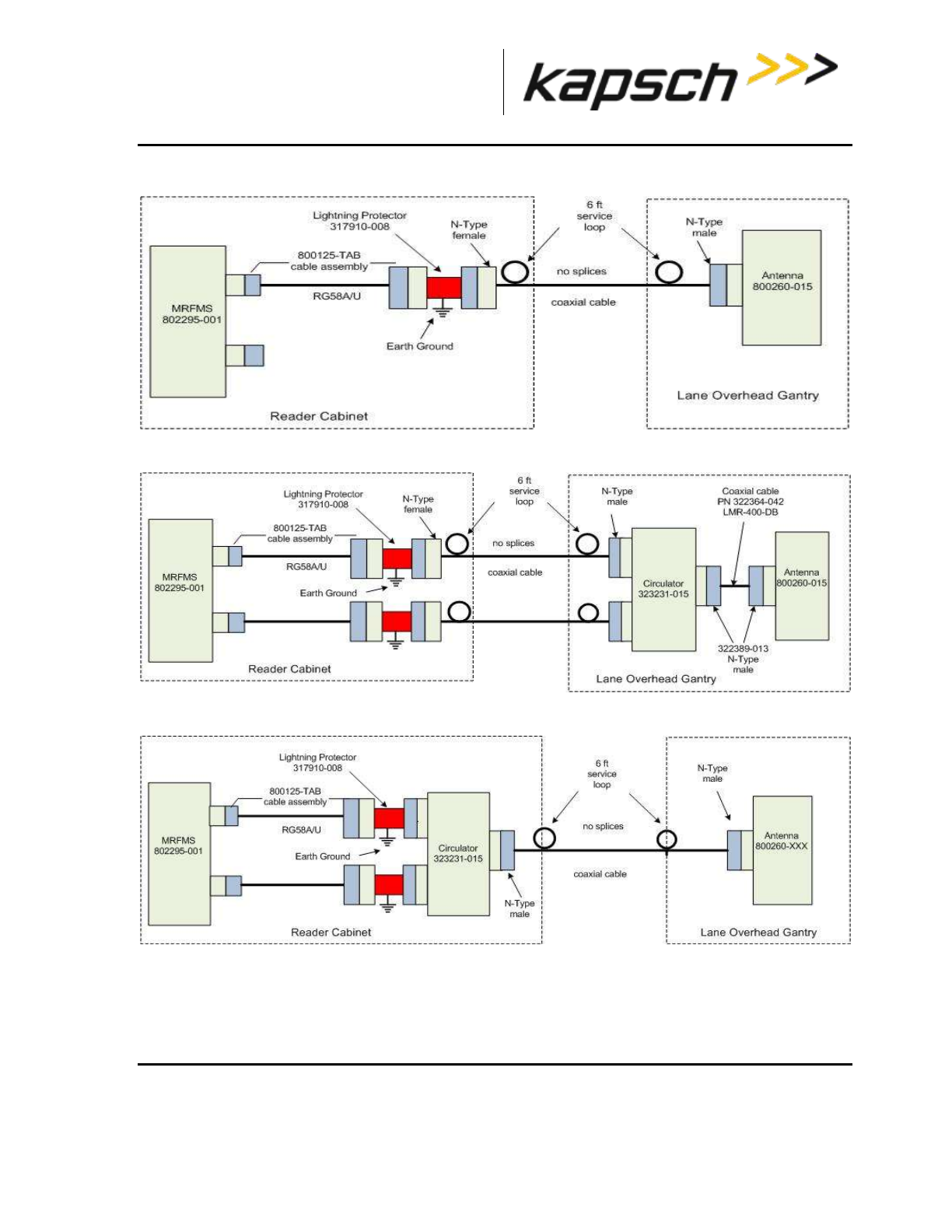
_
JANUS® Multi-Protocol Reader Ver. 2: Maintenance Instructions
Confidential UM 360463-202: A12 (Draft) Page 155 of 291
© Kapsch TrafficCom Canada Inc. 2013
These drawings and specifications contain confidential and proprietary information and are the property of Kapsch TrafficCom Canada Inc. and are issued in strict
confidence and will be kept confidential and used solely for the purpose intended and for no other purpose and shall not be transmitted, reproduced, copied, and/or
used as the basis for manufacture or sale of apparatus unless otherwise agreed to in writing by Kapsch TrafficCom Canada Inc.
FILE: MPR2_OPERATIONS_AND_MAINTENANCE-MANUAL_REV A12.DOCX 05/08/2014 11:24
Kapsch TrafficCom
Figure 5-6 RF Cable Installation Schematic Mono-Static Operation
Figure 5-7 RF Cable Installation Schematic Bi-Static Operation
Figure 5-8 RF Cable Installation Schematic Bi-Static TDM Only Operation
Performing Lane Tuning
Lane Tuning consist of selecting the frequencies to be used on the channels and setting the
attenuation for the channels to control the ERP of the reader. These are configured using the web

_
JANUS® Multi-Protocol Reader Ver. 2: Maintenance Instructions
Confidential UM 360463-202: A12 (Draft) Page 156 of 291
© Kapsch TrafficCom Canada Inc. 2013
These drawings and specifications contain confidential and proprietary information and are the property of Kapsch TrafficCom Canada Inc. and are issued in strict
confidence and will be kept confidential and used solely for the purpose intended and for no other purpose and shall not be transmitted, reproduced, copied, and/or
used as the basis for manufacture or sale of apparatus unless otherwise agreed to in writing by Kapsch TrafficCom Canada Inc.
FILE: MPR2_OPERATIONS_AND_MAINTENANCE-MANUAL_REV A12.DOCX 05/08/2014 11:24
Kapsch TrafficCom
interface. It is recommended that Kapsch Operations Group perform lane tuning to properly configure
a site. If the integrator/operator wishes to perform the lane tuning, the following guidelines apply:
The same FDM channel frequency should not be used on adjacent lanes (incl straddle and
shoulder).
The same TDM channel from 2 synchronized readers should not be used on adjacent lanes (incl
straddle and shoulder).
The TX attenuation should be adjusted to obtain capture zones nominally 8-12 ft along direction
of vehicle traffic.
Attention: When installing or replacing a MRFM-S, RF cables, circulator, or antenna, the lane must be
re-tuned.
The Synchronization circuit
Reader synchronization ensures antennas from different Readers do not attempt to communicate
simultaneously with the same on-board unit (OBU). The synchronization circuit connects SPMs
together in a star network. The CTM does the synchronization of the RF module interrogation.
Prerequisites: Sync hub terminal block mounted in a location central to the Readers. The exact
location of this terminal block should be marked on a site map to aid system maintenance.
Readers arranged so that no Reader is farther than 1500 feet from the sync hub terminal block
Readers arranged so that the total synchronization network cable length is no greater than 2000
feet
No more than six (6) Readers in the synchronization circuit
Note: It is recommended that each synchronization cable have two or more spare conductors to
support future service repair calls.
Installing a synchronization circuit
1. Connect the Readers to the Sync hub terminal block as in Figure 5-9 on page 159.
Attention: Ensure that cables do not connect from the GND terminal on the SPM to the
Sync hub terminal block, as this can create a ground loop and affect synchronization
performance.
Note: Before you continue, you will need to gain access to the CTM web Interface through a computer or
service laptop connected to the Ethernet 1 port or the USB port of the Reader. See the following
procedures for more information.
The Power output of a module at ambient (Pout(amb)) shall be constrained using
internal or external TX attenuation so that the following is satisfied:
Pout(amb): Gfund <= 43.77 dBmd - Gfund;
Where Gfund is the net gain from antenna connector on the RF module to the
antenna radiated signal where the antenna gain is expressed in dBd.
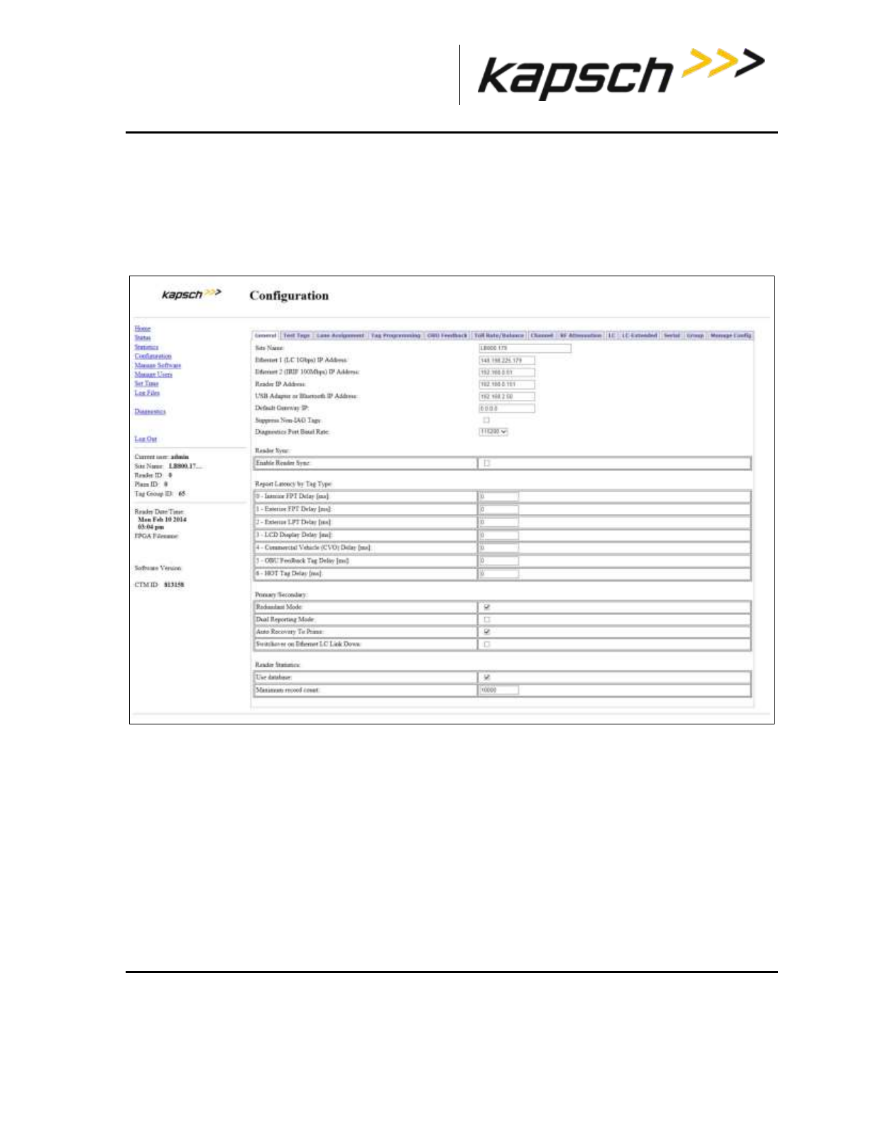
_
JANUS® Multi-Protocol Reader Ver. 2: Maintenance Instructions
Confidential UM 360463-202: A12 (Draft) Page 157 of 291
© Kapsch TrafficCom Canada Inc. 2013
These drawings and specifications contain confidential and proprietary information and are the property of Kapsch TrafficCom Canada Inc. and are issued in strict
confidence and will be kept confidential and used solely for the purpose intended and for no other purpose and shall not be transmitted, reproduced, copied, and/or
used as the basis for manufacture or sale of apparatus unless otherwise agreed to in writing by Kapsch TrafficCom Canada Inc.
FILE: MPR2_OPERATIONS_AND_MAINTENANCE-MANUAL_REV A12.DOCX 05/08/2014 11:24
Kapsch TrafficCom
Connecting a service laptop to the Reader on page 40
Changing the service laptop IP address on page 40
Testing the connection to the reader on page 40
Accessing the CTM web interface on page 41
2. Select the Configuration link on the left side panel.
Result: The following screen appears.
3. Select the Enable Reader Sync check box, if necessary.
Result: The following screen appears.
Note: Expanded Enable Reader Sync outlined in overlaid red box below.
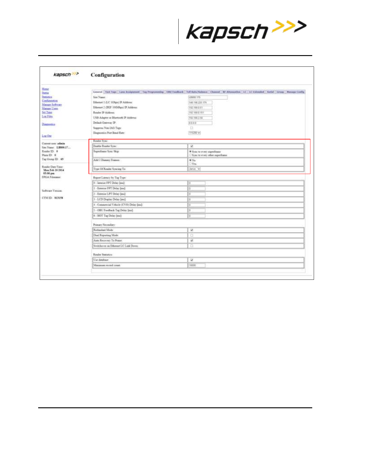
_
JANUS® Multi-Protocol Reader Ver. 2: Maintenance Instructions
Confidential UM 360463-202: A12 (Draft) Page 158 of 291
© Kapsch TrafficCom Canada Inc. 2013
These drawings and specifications contain confidential and proprietary information and are the property of Kapsch TrafficCom Canada Inc. and are issued in strict
confidence and will be kept confidential and used solely for the purpose intended and for no other purpose and shall not be transmitted, reproduced, copied, and/or
used as the basis for manufacture or sale of apparatus unless otherwise agreed to in writing by Kapsch TrafficCom Canada Inc.
FILE: MPR2_OPERATIONS_AND_MAINTENANCE-MANUAL_REV A12.DOCX 05/08/2014 11:24
Kapsch TrafficCom
4. Press Enter to accept selection.
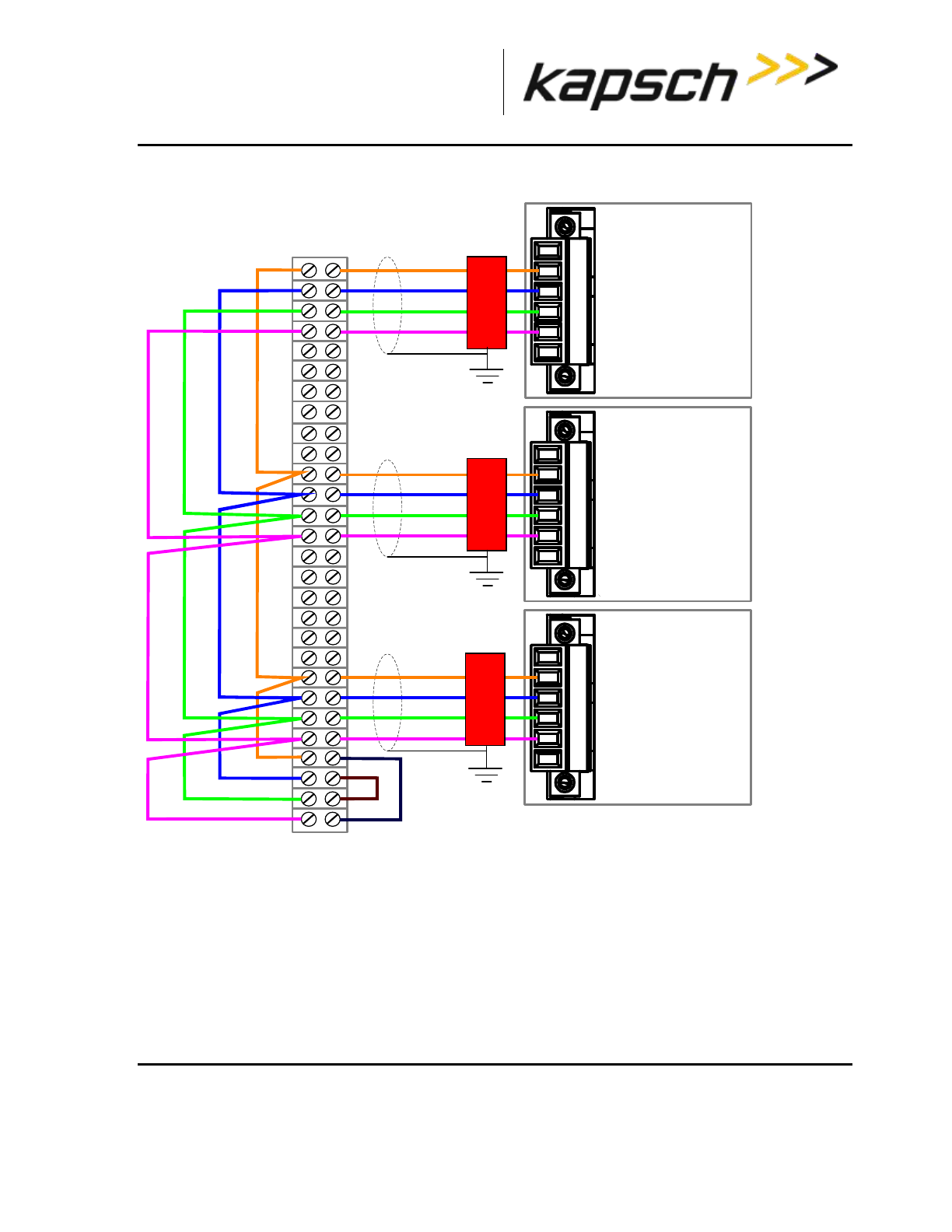
_
JANUS® Multi-Protocol Reader Ver. 2: Maintenance Instructions
Confidential UM 360463-202: A12 (Draft) Page 159 of 291
© Kapsch TrafficCom Canada Inc. 2013
These drawings and specifications contain confidential and proprietary information and are the property of Kapsch TrafficCom Canada Inc. and are issued in strict
confidence and will be kept confidential and used solely for the purpose intended and for no other purpose and shall not be transmitted, reproduced, copied, and/or
used as the basis for manufacture or sale of apparatus unless otherwise agreed to in writing by Kapsch TrafficCom Canada Inc.
FILE: MPR2_OPERATIONS_AND_MAINTENANCE-MANUAL_REV A12.DOCX 05/08/2014 11:24
Kapsch TrafficCom
Figure 5-9: Synchronization circuit schematic for three Readers
GND
SPM
Reader 1
GND
R-
R+
T+
T-
GND
GND
R-
R+
T+
T-
GND
GND
R-
R+
T+
T-
SPM
Reader 2
SPM
Reader 3
Sync hub terminal block
lightning
protector
Earth Ground
Earth Ground
Earth Ground
Shield
Synchronization between MPR2 Readers
All Readers in a synchronization circuit must be configured correctly for Synchronization to work. Also,
the number of frames per superframe must be equal between MPR2 Readers in the synchronization
circuit.
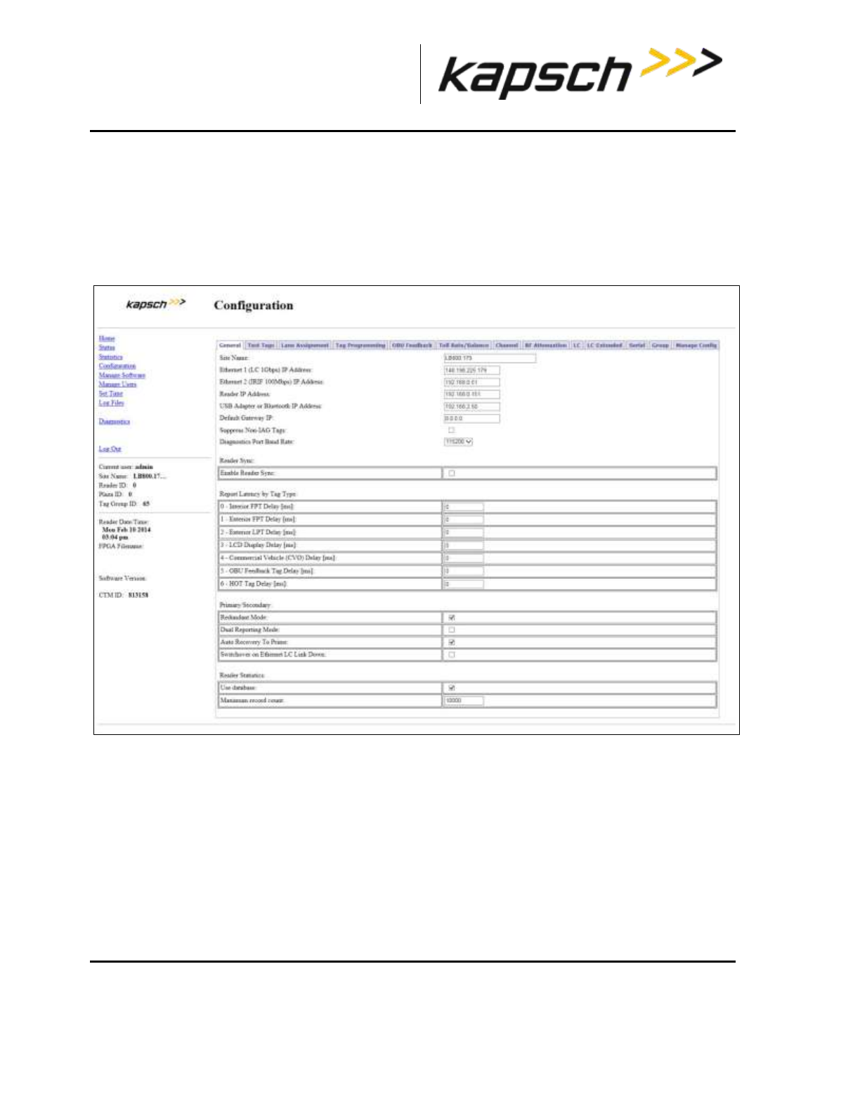
_
JANUS® Multi-Protocol Reader Ver. 2: Maintenance Instructions
Confidential UM 360463-202: A12 (Draft) Page 160 of 291
© Kapsch TrafficCom Canada Inc. 2013
These drawings and specifications contain confidential and proprietary information and are the property of Kapsch TrafficCom Canada Inc. and are issued in strict
confidence and will be kept confidential and used solely for the purpose intended and for no other purpose and shall not be transmitted, reproduced, copied, and/or
used as the basis for manufacture or sale of apparatus unless otherwise agreed to in writing by Kapsch TrafficCom Canada Inc.
FILE: MPR2_OPERATIONS_AND_MAINTENANCE-MANUAL_REV A12.DOCX 05/08/2014 11:24
Kapsch TrafficCom
Configuring synchronization
Prerequisites: Connect the service laptop to the Reader configuration port to access the CTM web
interface. Refer to Connecting a service laptop to the Reader, page 40.
Note: Reader synchronization also enabled remotely by the LC if the Remote LC Configuration is enabled.
1. Select the Configuration link on the left side panel.
Result: The following screen appears.
2. Select the Enable Reader Sync check box, if necessary.
Result: The synchronization settings appear.

_
JANUS® Multi-Protocol Reader Ver. 2: Maintenance Instructions
Confidential UM 360463-202: A12 (Draft) Page 161 of 291
© Kapsch TrafficCom Canada Inc. 2013
These drawings and specifications contain confidential and proprietary information and are the property of Kapsch TrafficCom Canada Inc. and are issued in strict
confidence and will be kept confidential and used solely for the purpose intended and for no other purpose and shall not be transmitted, reproduced, copied, and/or
used as the basis for manufacture or sale of apparatus unless otherwise agreed to in writing by Kapsch TrafficCom Canada Inc.
FILE: MPR2_OPERATIONS_AND_MAINTENANCE-MANUAL_REV A12.DOCX 05/08/2014 11:24
Kapsch TrafficCom
3. Select Sync to Every Superframe in the Superframe Sync Skip row.
4. Select No in the Add 2 Dummy Frames row.
5. Select JANUS from the drop-down box in the Type of Reader Synching To row.
6. Repeat these steps for all Readers in the Synchronization circuit.
7. When you are finished, press Enter to accept the selections.
Synchronization between JANUS® Readers and BADGER Readers
JANUS® and BADGER Readers in the same synchronization network can be configured as in step 1 in the
procedure Synchronization between MPR2 Readers. However, JANUS® and BADGER Readers can also have the
superframe configurations shown in Table 5-3 on page 164.
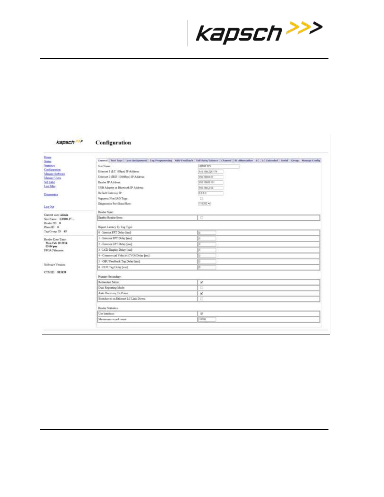
_
JANUS® Multi-Protocol Reader Ver. 2: Maintenance Instructions
Confidential UM 360463-202: A12 (Draft) Page 162 of 291
© Kapsch TrafficCom Canada Inc. 2013
These drawings and specifications contain confidential and proprietary information and are the property of Kapsch TrafficCom Canada Inc. and are issued in strict
confidence and will be kept confidential and used solely for the purpose intended and for no other purpose and shall not be transmitted, reproduced, copied, and/or
used as the basis for manufacture or sale of apparatus unless otherwise agreed to in writing by Kapsch TrafficCom Canada Inc.
FILE: MPR2_OPERATIONS_AND_MAINTENANCE-MANUAL_REV A12.DOCX 05/08/2014 11:24
Kapsch TrafficCom
Configuring Synchronization
Prerequisites: Connect the service laptop to the Reader configuration port to access the CTM web
interface. Refer to Connecting a service laptop to the Reader, page 40.
Note: Reader synchronization can also be enabled remotely by the LC if Remote LC Configuration is
enabled.
1. Select the Configuration link on the left side panel.
Result: The following screen appears.
2. Select the Enable Reader Sync check box, if necessary.
Result: The synchronization settings appear.
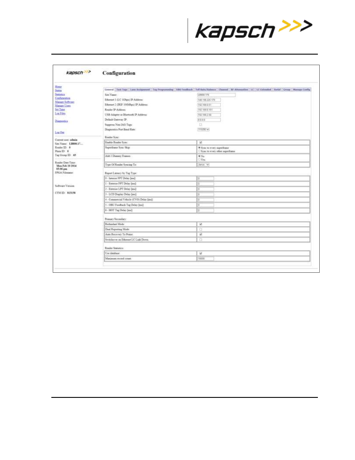
_
JANUS® Multi-Protocol Reader Ver. 2: Maintenance Instructions
Confidential UM 360463-202: A12 (Draft) Page 163 of 291
© Kapsch TrafficCom Canada Inc. 2013
These drawings and specifications contain confidential and proprietary information and are the property of Kapsch TrafficCom Canada Inc. and are issued in strict
confidence and will be kept confidential and used solely for the purpose intended and for no other purpose and shall not be transmitted, reproduced, copied, and/or
used as the basis for manufacture or sale of apparatus unless otherwise agreed to in writing by Kapsch TrafficCom Canada Inc.
FILE: MPR2_OPERATIONS_AND_MAINTENANCE-MANUAL_REV A12.DOCX 05/08/2014 11:24
Kapsch TrafficCom
3. If the configuration is not already set, then set Superframe Sync Skip to Select Sync to Every
Superframe, set Add 2 Dummy Frames to No, set Type of Reader Syncing to to JANUS or BADGER,
as applicable.
4. Press Enter to accept the selections.
5. If the superframes for all Readers will be equal (4, 5, or 8 frames) go to Synchronization between MPR2
Readers and perform step 1.
6. If the superframes will be configured as shown in Table 5-3, configure the Superframe Sync Skip and
Add 2 Dummy Frames parameters in the General tab on the Configuration page as outlined in Table
5-3 on page 164.

_
JANUS® Multi-Protocol Reader Ver. 2: Maintenance Instructions
Confidential UM 360463-202: A12 (Draft) Page 164 of 291
© Kapsch TrafficCom Canada Inc. 2013
These drawings and specifications contain confidential and proprietary information and are the property of Kapsch TrafficCom Canada Inc. and are issued in strict
confidence and will be kept confidential and used solely for the purpose intended and for no other purpose and shall not be transmitted, reproduced, copied, and/or
used as the basis for manufacture or sale of apparatus unless otherwise agreed to in writing by Kapsch TrafficCom Canada Inc.
FILE: MPR2_OPERATIONS_AND_MAINTENANCE-MANUAL_REV A12.DOCX 05/08/2014 11:24
Kapsch TrafficCom
Table 5-3: Synchronization Compatibility Matrix – JANUS® and BADGER
JANUS® Reader
superframe size
Superframe Sync
Skip
Add two
dummy
frames
BADGER
Reader
superframe size
Superframe
Sync Skip
Add two
dummy
frames
4 frames
sync to every
other superframe
No
8 frames
sync to every
superframe
No
8 frames
sync to every
superframe
No
4 frames
sync to every
other
superframe
No
5 frames
sync to every
other superframe
No
10 frames
sync to every
superframe
Yes (with 8
active or
offline RF
channels)
10 frames
sync to every
superframe
Yes (with 8
active or
offline RF
channels)
5 frames
sync to every
other
superframe
No
The Ethernet Network
These are general instructions for using Ethernet Switch Modules (ESMs) to create an Inter-Reader
(IR) Ethernet network or a Lane Controller (LC) Ethernet network.
Installing an Ethernet network
Prerequisites: ESMs mounted according to the manufacturer’s instructions.
1. Use CAT 6 Ethernet cables to connect the components in the Ethernet network together as shown in the
examples in Figure 5-10. Consult the ESM manufacturer’s instructions for more details.
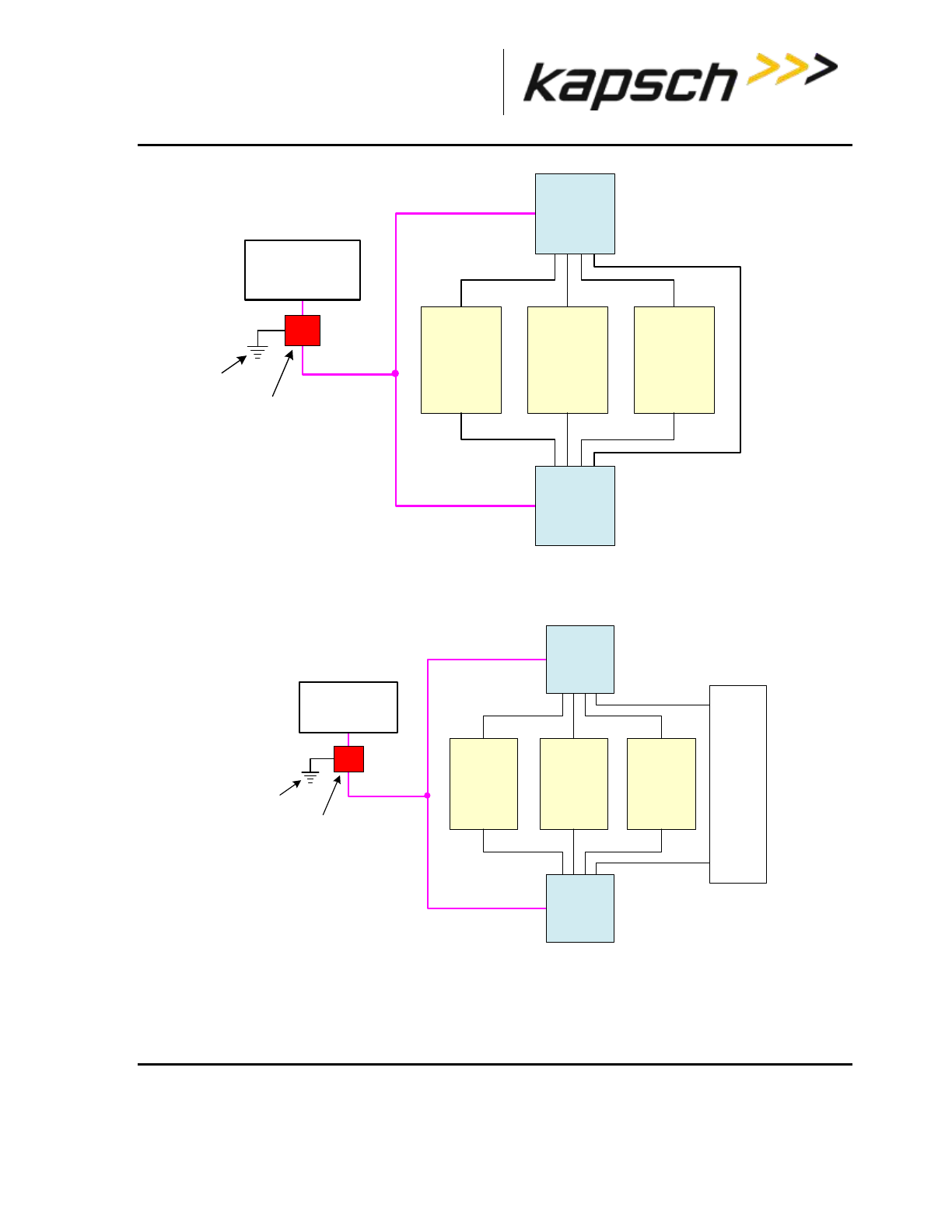
_
JANUS® Multi-Protocol Reader Ver. 2: Maintenance Instructions
Confidential UM 360463-202: A12 (Draft) Page 165 of 291
© Kapsch TrafficCom Canada Inc. 2013
These drawings and specifications contain confidential and proprietary information and are the property of Kapsch TrafficCom Canada Inc. and are issued in strict
confidence and will be kept confidential and used solely for the purpose intended and for no other purpose and shall not be transmitted, reproduced, copied, and/or
used as the basis for manufacture or sale of apparatus unless otherwise agreed to in writing by Kapsch TrafficCom Canada Inc.
FILE: MPR2_OPERATIONS_AND_MAINTENANCE-MANUAL_REV A12.DOCX 05/08/2014 11:24
Kapsch TrafficCom
Ethernet 2
Primary
Reader 1
Secondary
Ethernet 2
Ethernet 2
Primary
Reader 2
Secondary
Ethernet 2
Ethernet 2
Primary
Reader 3
Secondary
Ethernet 2
Lightning
protector
Earth ground
system
Secondary
ESM
4 port
Primary
ESM
4 port
Power mains
85-264 VAC
or 88-300 VDC
Figure 5-10: Schematic of a three-Reader IR network
Ethernet 1
Primary
Reader 1
Secondary
Ethernet 1
Ethernet 1
Primary
Reader 2
Secondary
Ethernet 1
Ethernet 1
Primary
Reader 3
Secondary
Ethernet 1
Lightning
protector
Earth ground
system
Secondary
ESM
4 port
Primary
ESM
4 port
Power mains
85-264 VAC
or 88-300 VDC
Lane
Controller
Primary
Ethernet
Port
Secondary
Ethernet
Port
Figure 5-11: Schematic of a three-Reader LC network
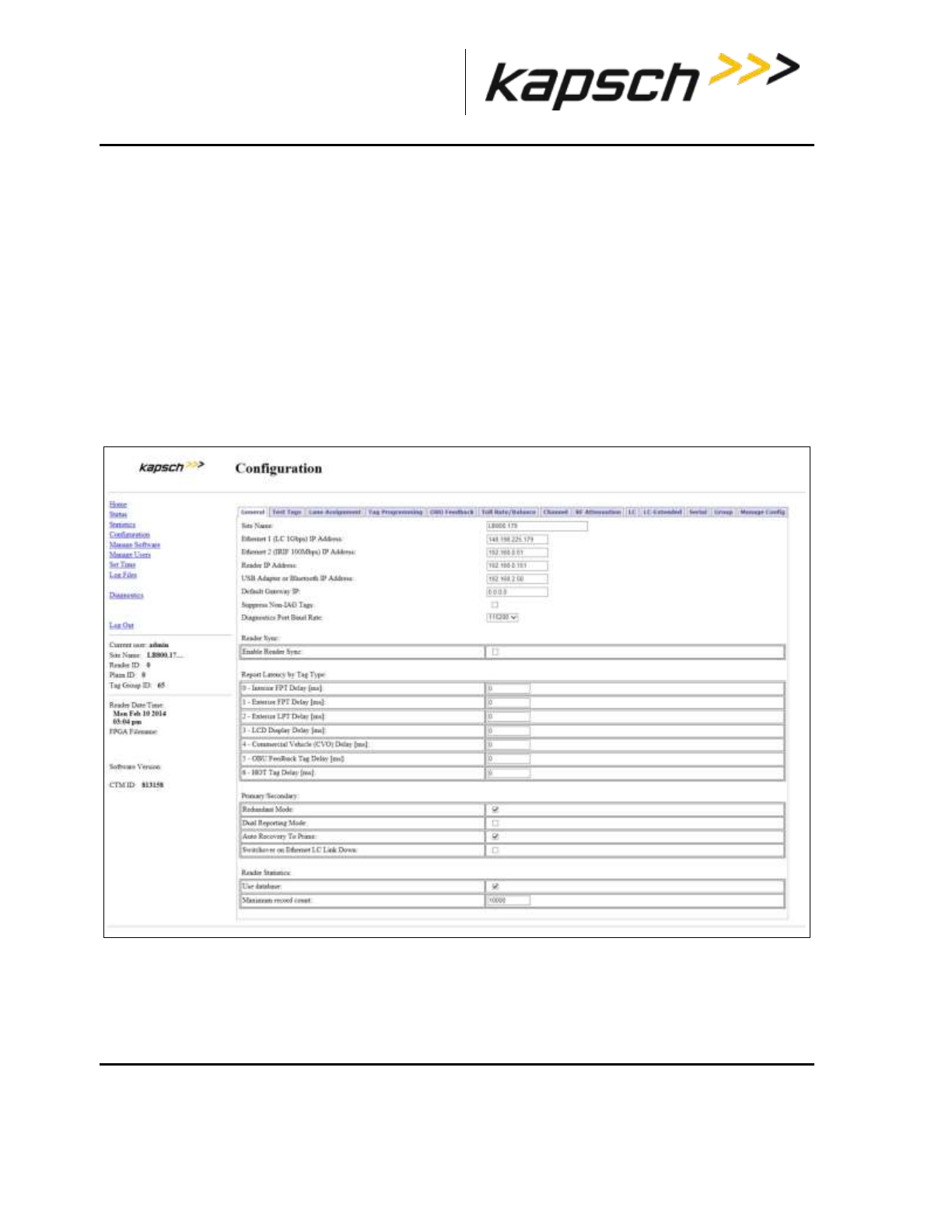
_
JANUS® Multi-Protocol Reader Ver. 2: Maintenance Instructions
Confidential UM 360463-202: A12 (Draft) Page 166 of 291
© Kapsch TrafficCom Canada Inc. 2013
These drawings and specifications contain confidential and proprietary information and are the property of Kapsch TrafficCom Canada Inc. and are issued in strict
confidence and will be kept confidential and used solely for the purpose intended and for no other purpose and shall not be transmitted, reproduced, copied, and/or
used as the basis for manufacture or sale of apparatus unless otherwise agreed to in writing by Kapsch TrafficCom Canada Inc.
FILE: MPR2_OPERATIONS_AND_MAINTENANCE-MANUAL_REV A12.DOCX 05/08/2014 11:24
Kapsch TrafficCom
Reader connections to the LC via the LPM serial ports
Each of the RF channels has an associated serial port on the LPM that connects to an LC.
Configuring reader connections
The following steps provide information on configuring the reader connections to the LC via the LPM
serial ports.
Prerequisites: Connect the service laptop to the Reader configuration port to access the CTM web
interface. Refer to Connecting a service laptop to the Reader, page 40. You must have
Advanced User permissions.
1. Determine your Reader’s communications protocol. It will be either RS-232 or RS-422.
2. Select the Configuration link on the left side panel.
Result: The following screen appears.
3. Click the LC tab.
Result: The following screen appears.
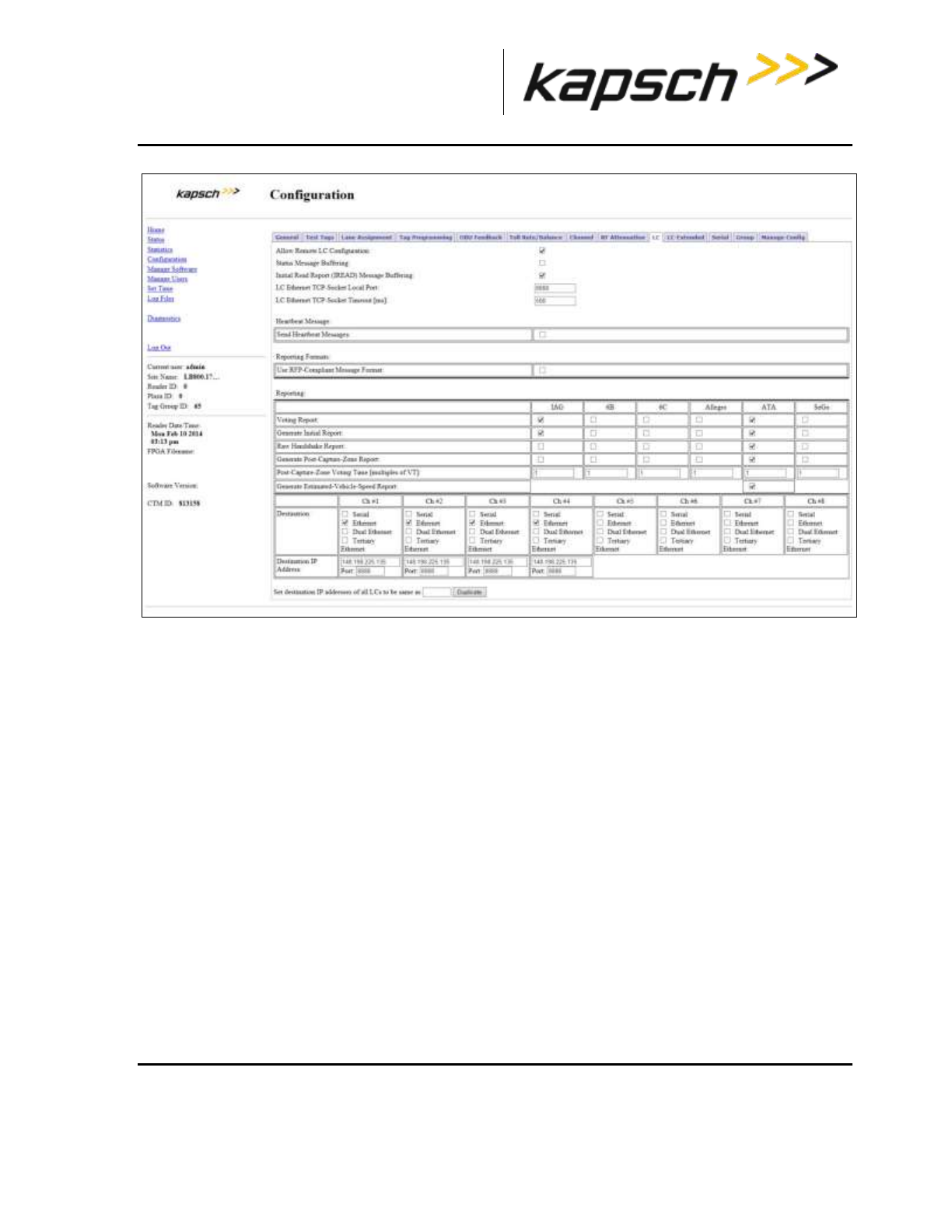
_
JANUS® Multi-Protocol Reader Ver. 2: Maintenance Instructions
Confidential UM 360463-202: A12 (Draft) Page 167 of 291
© Kapsch TrafficCom Canada Inc. 2013
These drawings and specifications contain confidential and proprietary information and are the property of Kapsch TrafficCom Canada Inc. and are issued in strict
confidence and will be kept confidential and used solely for the purpose intended and for no other purpose and shall not be transmitted, reproduced, copied, and/or
used as the basis for manufacture or sale of apparatus unless otherwise agreed to in writing by Kapsch TrafficCom Canada Inc.
FILE: MPR2_OPERATIONS_AND_MAINTENANCE-MANUAL_REV A12.DOCX 05/08/2014 11:24
Kapsch TrafficCom
4. In the Destination row, select the Serial check box for each RF channel that will communicate with the
LC via an LPM COM Port.
Example: The following screen shows an example of the assignments.
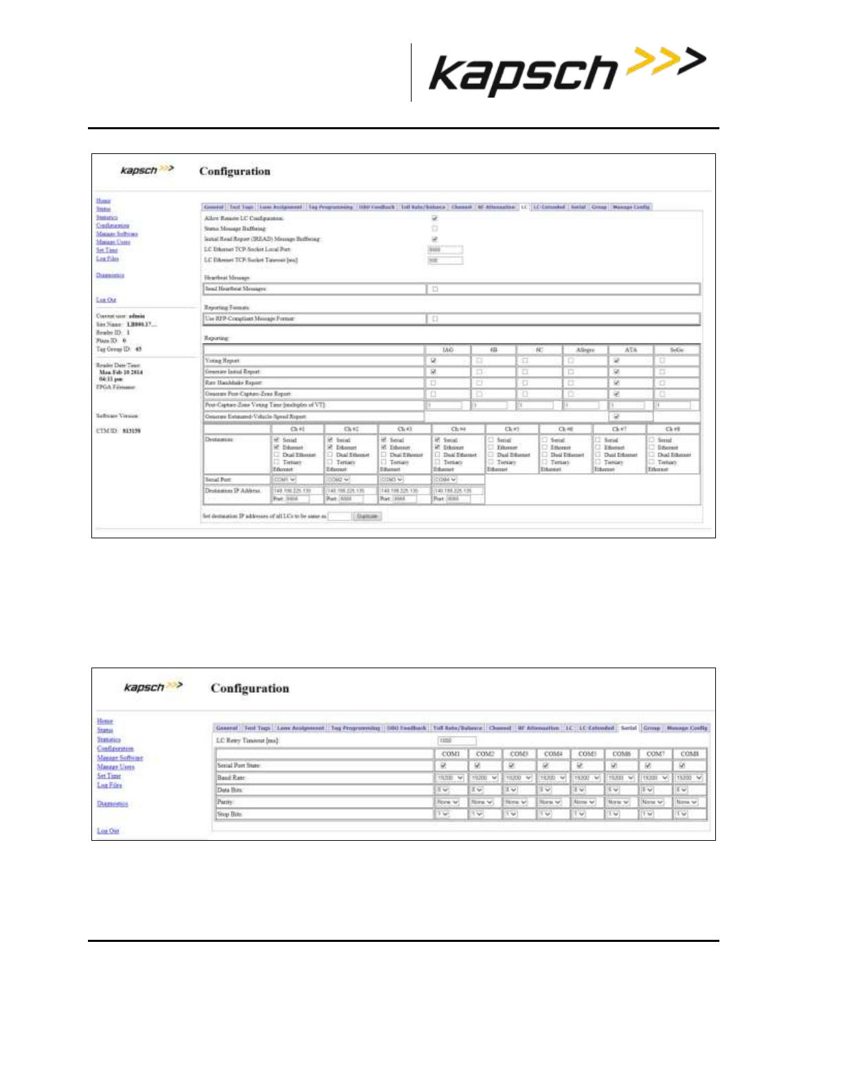
_
JANUS® Multi-Protocol Reader Ver. 2: Maintenance Instructions
Confidential UM 360463-202: A12 (Draft) Page 168 of 291
© Kapsch TrafficCom Canada Inc. 2013
These drawings and specifications contain confidential and proprietary information and are the property of Kapsch TrafficCom Canada Inc. and are issued in strict
confidence and will be kept confidential and used solely for the purpose intended and for no other purpose and shall not be transmitted, reproduced, copied, and/or
used as the basis for manufacture or sale of apparatus unless otherwise agreed to in writing by Kapsch TrafficCom Canada Inc.
FILE: MPR2_OPERATIONS_AND_MAINTENANCE-MANUAL_REV A12.DOCX 05/08/2014 11:24
Kapsch TrafficCom
5. From the Serial Port dropdowns, select an LPM port for each RF channel to use to communicate with the
LC. By default, RF Channel 1 communicates with the LC via LPM COM 1, RF Channel 2 communicates
with the LC via LPM COM 2 and so on up to RF Channel 8.
Note: More than one RF Channel can communicate via one LPM COM port, if necessary.
6. Click the Serial tab on the Configuration page.
Result: The following screen appears.
7. Ensure all the COM Ports selected in step 5 are enabled by selecting the corresponding Serial Port
State check box.
8. Select the Baud Rate, Data Bits, Parity, and Stop Bits to match the LC communication settings.
9. Press Enter to accept the configuration.

_
JANUS® Multi-Protocol Reader Ver. 2: Maintenance Instructions
Confidential UM 360463-202: A12 (Draft) Page 169 of 291
© Kapsch TrafficCom Canada Inc. 2013
These drawings and specifications contain confidential and proprietary information and are the property of Kapsch TrafficCom Canada Inc. and are issued in strict
confidence and will be kept confidential and used solely for the purpose intended and for no other purpose and shall not be transmitted, reproduced, copied, and/or
used as the basis for manufacture or sale of apparatus unless otherwise agreed to in writing by Kapsch TrafficCom Canada Inc.
FILE: MPR2_OPERATIONS_AND_MAINTENANCE-MANUAL_REV A12.DOCX 05/08/2014 11:24
Kapsch TrafficCom
Refer to the Configuring the Reader to switch automatically over when an LC link is down procedure on page 232
to configure the Reader to switch over when the connection from the LPM to the LC is down.
IP addresses
Each ethernet port in an IR or LC network must have a unique IP address. The IP addresses should be
set as required for the site network topology. Default IP addresses are:
Primary and secondary Ethernet 1 port: 192.168.1.50
Primary side Ethernet 2 port: 192.168.0.50
Secondary side Ethernet 2 port: 192.168.0.51
Setting the IP addresses
Prerequisites: Connect the service laptop to the Reader configuration port to access the CTM web
interface. Refer to Connecting a service laptop to the Reader, page 40.
Note: A secure record of the IP addresses should be maintained to aid network troubleshooting. The primary
and secondary Ethernet 1 IP addresses will be required if requesting remote assistance from Kapsch Service.
1. Select the Configuration link on the left side panel.
Result: The following screen appears.

_
JANUS® Multi-Protocol Reader Ver. 2: Maintenance Instructions
Confidential UM 360463-202: A12 (Draft) Page 170 of 291
© Kapsch TrafficCom Canada Inc. 2013
These drawings and specifications contain confidential and proprietary information and are the property of Kapsch TrafficCom Canada Inc. and are issued in strict
confidence and will be kept confidential and used solely for the purpose intended and for no other purpose and shall not be transmitted, reproduced, copied, and/or
used as the basis for manufacture or sale of apparatus unless otherwise agreed to in writing by Kapsch TrafficCom Canada Inc.
FILE: MPR2_OPERATIONS_AND_MAINTENANCE-MANUAL_REV A12.DOCX 05/08/2014 11:24
Kapsch TrafficCom
2. Assign an IP address to the parameter Ethernet 1 (LC 1Gbps) IP Address so that the Primary CTM is
accessible on the LC network, if necessary.
3. Assign an IP address to the parameter Ethernet 2 (IRIF 100Mbps) IP Address so that the Primary CTM
is accessible on the IR network, if necessary.
4. Assign an IP address to the parameter Reader IP Address for both primary and secondary CTMs on a
given Reader so that the Reader is accessible on the IR network, if necessary. This IP address is the
same for both CTMs in a Reader.
5. Assign an IP address to the parameter USB Adapter IP Address if a USB adapter is being used to
connect a CTM USB port to an Ethernet network.
6. Assign the gateway IP address to the parameter Default Gateway IP so that the Reader can
communicate via a gateway device such as a router, if necessary.
7. Press Enter to accept all addresses.
8. Repeat steps 1 through 7 for the secondary CTM.
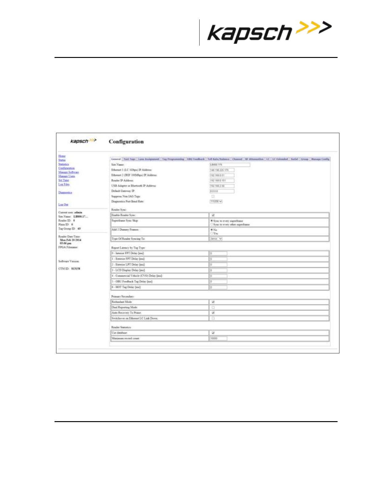
_
JANUS® Multi-Protocol Reader Ver. 2: Maintenance Instructions
Confidential UM 360463-202: A12 (Draft) Page 171 of 291
© Kapsch TrafficCom Canada Inc. 2013
These drawings and specifications contain confidential and proprietary information and are the property of Kapsch TrafficCom Canada Inc. and are issued in strict
confidence and will be kept confidential and used solely for the purpose intended and for no other purpose and shall not be transmitted, reproduced, copied, and/or
used as the basis for manufacture or sale of apparatus unless otherwise agreed to in writing by Kapsch TrafficCom Canada Inc.
FILE: MPR2_OPERATIONS_AND_MAINTENANCE-MANUAL_REV A12.DOCX 05/08/2014 11:24
Kapsch TrafficCom
Configuring an LC Ethernet network
The Reader data can also be sent to the LC via an Ethernet network.
Prerequisites: The service laptop connects to the port and the CTM web accessed. . Refer to
Connecting a service laptop to the Reader, page 40. You must have Advanced User
permissions.
1. Select the Configuration link on the left side panel.
Result: The following screen appears.
2. Click the LC tab.
Result: The following screen appears.
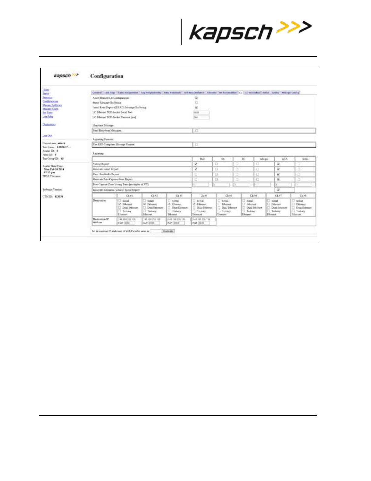
_
JANUS® Multi-Protocol Reader Ver. 2: Maintenance Instructions
Confidential UM 360463-202: A12 (Draft) Page 172 of 291
© Kapsch TrafficCom Canada Inc. 2013
These drawings and specifications contain confidential and proprietary information and are the property of Kapsch TrafficCom Canada Inc. and are issued in strict
confidence and will be kept confidential and used solely for the purpose intended and for no other purpose and shall not be transmitted, reproduced, copied, and/or
used as the basis for manufacture or sale of apparatus unless otherwise agreed to in writing by Kapsch TrafficCom Canada Inc.
FILE: MPR2_OPERATIONS_AND_MAINTENANCE-MANUAL_REV A12.DOCX 05/08/2014 11:24
Kapsch TrafficCom
3. In the Destination row, select the Ethernet check box for each RF channel that will communicate with
the LC via Ethernet.
4. Enter the LC IP address and Port number for each RF channel.
5. If all the RF channels will be communicating with the LC at the same IP address, enter the number of a
configured channel in the field beside the Duplicate button and then click Duplicate.
Result: All RF channels selected to communicate over Ethernet will now have the same destination LC
IP.
Note: When setting the LC Retry Timeout, consider the baud rate used to communicate with the LC and
the processing speed of the LC to avoid false failure reports.
6. Enter a time, in milliseconds, in the LC Ethernet TCP-Socket Timeout field.
7. Press Enter to accept your selections and inputs.
Note: If an LC does not respond within this time, the Reader will consider Ethernet communications to the
LC to be down and could trigger a switchover, depending on the redundancy settings.
Configuring the Ethernet 1 IP address via the Diagnostic Port
Contact Kapsch Service to set the ETHERNET 1 port IP address via the Diagnostic Port if the IP
address has been lost or cannot be determined.
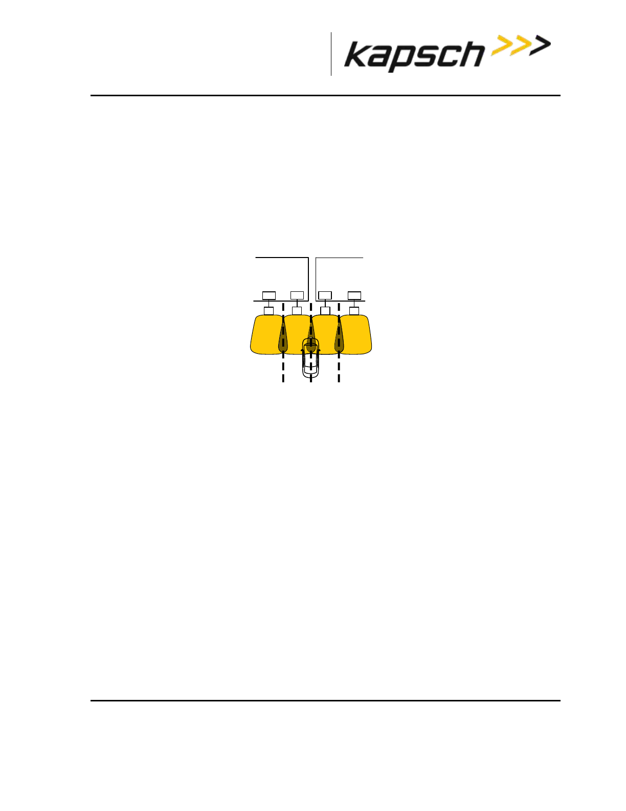
_
JANUS® Multi-Protocol Reader Ver. 2: Maintenance Instructions
Confidential UM 360463-202: A12 (Draft) Page 173 of 291
© Kapsch TrafficCom Canada Inc. 2013
These drawings and specifications contain confidential and proprietary information and are the property of Kapsch TrafficCom Canada Inc. and are issued in strict
confidence and will be kept confidential and used solely for the purpose intended and for no other purpose and shall not be transmitted, reproduced, copied, and/or
used as the basis for manufacture or sale of apparatus unless otherwise agreed to in writing by Kapsch TrafficCom Canada Inc.
FILE: MPR2_OPERATIONS_AND_MAINTENANCE-MANUAL_REV A12.DOCX 05/08/2014 11:24
Kapsch TrafficCom
Lane Assignment voting for ORT applications
ORT lanes allow OBUs to cross multiple capture zones. The Readers must assign an OBU to one RF
channel to prevent duplicate transactions.
Selecting the correct communication method
The communication method determines how Readers communicate with each other to share
information for determining lane assignments. This is important for situations similar to that shown in
Figure 5-12, where, to assign the OBU to a lane, Reader 1 and Reader 2 need to share handshaking
information.
Figure 5-12: Two Readers communicating with one OBU
Configuring Lane Voting over an Inter-Reader (IR) network
This procedure allows you to configure the Reader correctly to ensure accurate lane assignment and to
prevent duplicate reports.
Prerequisites: Connect the service laptop to the Reader configuration port to access the CTM web
interface. Refer to Connecting a service laptop to the Reader, page 40. You must have Advanced
User permissions.
Note: Badger-Style CRA: there is no physical link between the Readers, such as an IR Network.
Instead, the first Reader to contact an OBU programs the OBU; all other Readers that subsequently
contact the OBU will see that it was recently programmed and ignore the OBU.
Ethernet: An IR Ethernet network connects the Readers together and handshaking information is
shared between Readers. The Readers assign the OBU to one channel and all other transaction
reports from other Readers are suppressed.
1. Select the Configuration link on the left side panel.
Result: The following screen appears.
A5 A6
Reader 1
RF5 RF6
Reader 2
A4
RF4
A7
RF7
slot 4 slot 5 slot 1 slot 2
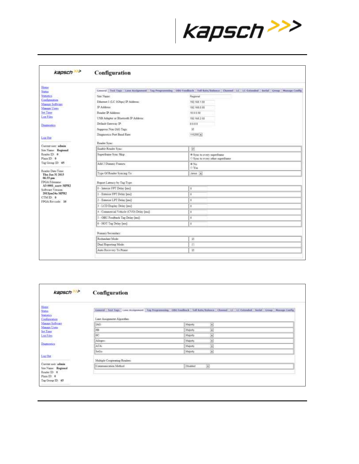
_
JANUS® Multi-Protocol Reader Ver. 2: Maintenance Instructions
Confidential UM 360463-202: A12 (Draft) Page 174 of 291
© Kapsch TrafficCom Canada Inc. 2013
These drawings and specifications contain confidential and proprietary information and are the property of Kapsch TrafficCom Canada Inc. and are issued in strict
confidence and will be kept confidential and used solely for the purpose intended and for no other purpose and shall not be transmitted, reproduced, copied, and/or
used as the basis for manufacture or sale of apparatus unless otherwise agreed to in writing by Kapsch TrafficCom Canada Inc.
FILE: MPR2_OPERATIONS_AND_MAINTENANCE-MANUAL_REV A12.DOCX 05/08/2014 11:24
Kapsch TrafficCom
2. Click the Lane Assignment tab.
Result: The following screen appears.
3. Select Ethernet from the Communication Method drop-down box.
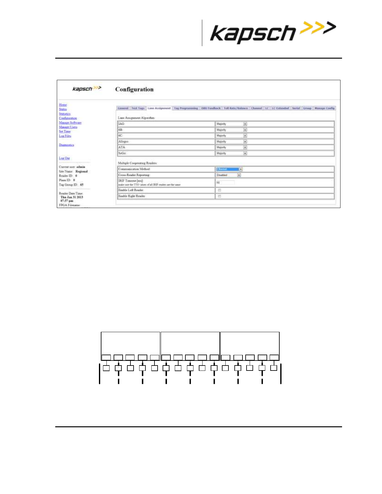
_
JANUS® Multi-Protocol Reader Ver. 2: Maintenance Instructions
Confidential UM 360463-202: A12 (Draft) Page 175 of 291
© Kapsch TrafficCom Canada Inc. 2013
These drawings and specifications contain confidential and proprietary information and are the property of Kapsch TrafficCom Canada Inc. and are issued in strict
confidence and will be kept confidential and used solely for the purpose intended and for no other purpose and shall not be transmitted, reproduced, copied, and/or
used as the basis for manufacture or sale of apparatus unless otherwise agreed to in writing by Kapsch TrafficCom Canada Inc.
FILE: MPR2_OPERATIONS_AND_MAINTENANCE-MANUAL_REV A12.DOCX 05/08/2014 11:24
Kapsch TrafficCom
Result: The following screen appears.
Configure how multiple transactions are reported to the LC:
To send one transaction report per OBU to the LC without informing the LC of suppressed reports, select
Disabled from the Cross-Reader Reporting drop-down box.
To send all transaction reports for an OBU to the LC, select Report All from the Cross-Reader
Reporting drop-down box.
To send on transaction report per OBU to the LC and also inform the LC of suppressed reports, select
Report Non-zero from the Cross-Reader Reporting drop-down box.
1. Configure the IR network by determining where the Reader sits in the IR network.
Example: Reader 1 in Figure 5-13 has a Reader on its right (Reader 2) but no Reader on the left. Reader
2 in Figure 5-13 has a Reader on its right (Reader 3) and a Reader on its left (Reader 1). Reader 3 in
Figure 5-13 does not have a Reader on its right but has one on its left (Reader 2).
Figure 5-13: Three readers covering one direction of wide lane ORT traffic
Note: The Reader IP address applies to the whole Reader and not individual Ethernet ports. You can
view the Reader IP address in the General tab of the Configuration page.
2. If there is a Reader on the left, select the Enable Left Reader check box.
3. Enter the Reader IP address of the left Reader.
lane 1
Reader 1
(left Reader)
A1
RF1
A2
RF2
A3
RF3
A4
RF4
A5
RF5
lane 2 lane 3
Reader 2
(center Reader)
A6
RF6
A7
RF7
A8
RF8
A9
RF9
lane 4 lane 5
Reader 3
(right Reader)
lane 6 lane 8lane 7
RF10
A10
RF11
A11
RF12
A12
RF13
A13
RF14
A14
RF15
A15

_
JANUS® Multi-Protocol Reader Ver. 2: Maintenance Instructions
Confidential UM 360463-202: A12 (Draft) Page 176 of 291
© Kapsch TrafficCom Canada Inc. 2013
These drawings and specifications contain confidential and proprietary information and are the property of Kapsch TrafficCom Canada Inc. and are issued in strict
confidence and will be kept confidential and used solely for the purpose intended and for no other purpose and shall not be transmitted, reproduced, copied, and/or
used as the basis for manufacture or sale of apparatus unless otherwise agreed to in writing by Kapsch TrafficCom Canada Inc.
FILE: MPR2_OPERATIONS_AND_MAINTENANCE-MANUAL_REV A12.DOCX 05/08/2014 11:24
Kapsch TrafficCom
4. Press Enter or select a different tab.
5. If there is a Reader on the right, select the Enable Right Reader check box.
6. Enter the Reader IP address of the right Reader.
7. Press Enter or select a different tab.
8. TTO values for the grouped IDs must be the same across all readers.
9. A reader restart is required when the IR network configuration is complete
10. To set the Reader to switchover when an IR link is down, see the Configuring events that cause a
switchover procedure, page 231.
11. Configure Tag Programming (see OBU Programming on page 61) ensuring that:
TMP and TCP are enabled
The Plaza IDs of all Readers at the plaza match
The Reader ID for each Reader is different
12. Configure the Reader clocks in the IR network to have the same time (see Using an NTP Server to
synchronize the clocks of Readers in an IR network, page 254).
Note: Multiple group IDs are not supported across multiple readers.
13. From the Channel tab on the Configuration page, ensure all channels covering one direction of traffic
have the same Group ID.
Configuring Badger-style Cross Reader Algorithm (CRA) communication
Prerequisites: Connect the service laptop to the Reader configuration port to access the CTM web
interface. Refer to Connecting a service laptop to the Reader, page 40.
1. Select the Configuration link on the left side panel.
Result: The following screen appears.

_
JANUS® Multi-Protocol Reader Ver. 2: Maintenance Instructions
Confidential UM 360463-202: A12 (Draft) Page 177 of 291
© Kapsch TrafficCom Canada Inc. 2013
These drawings and specifications contain confidential and proprietary information and are the property of Kapsch TrafficCom Canada Inc. and are issued in strict
confidence and will be kept confidential and used solely for the purpose intended and for no other purpose and shall not be transmitted, reproduced, copied, and/or
used as the basis for manufacture or sale of apparatus unless otherwise agreed to in writing by Kapsch TrafficCom Canada Inc.
FILE: MPR2_OPERATIONS_AND_MAINTENANCE-MANUAL_REV A12.DOCX 05/08/2014 11:24
Kapsch TrafficCom
2. Click the Lane Assignment tab.
Result: The following screen appears.
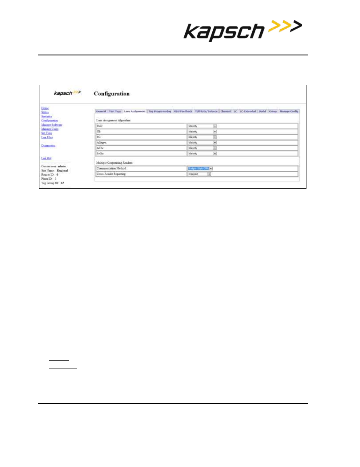
_
JANUS® Multi-Protocol Reader Ver. 2: Maintenance Instructions
Confidential UM 360463-202: A12 (Draft) Page 178 of 291
© Kapsch TrafficCom Canada Inc. 2013
These drawings and specifications contain confidential and proprietary information and are the property of Kapsch TrafficCom Canada Inc. and are issued in strict
confidence and will be kept confidential and used solely for the purpose intended and for no other purpose and shall not be transmitted, reproduced, copied, and/or
used as the basis for manufacture or sale of apparatus unless otherwise agreed to in writing by Kapsch TrafficCom Canada Inc.
FILE: MPR2_OPERATIONS_AND_MAINTENANCE-MANUAL_REV A12.DOCX 05/08/2014 11:24
Kapsch TrafficCom
3. Select Badger-Style CRA from the Communication Method drop-down box.
Result: The following screen appears.
4. Configure how multiple transactions are reported to the LC:
To send one transaction report per OBU to the LC without informing the LC of suppressed reports,
select Disabled from the Cross-Reader Reporting drop-down box.
To send on transaction report per OBU to the LC and also inform the LC of suppressed reports,
select Report Non-zero from the Cross-Reader Reporting drop-down box.
5. Configure Tag Programming (see OBU Programming on page 61) ensuring that:
TMP and TCP are enabled
the Plaza IDs of all Readers at the plaza match
the Reader ID for each Reader is different
Note: Multiple group IDs are not supported across multiple Readers.
6. From the Channel tab on the Configuration page, ensure all channels covering one direction of traffic
have the same Group ID.
Note: The transponder timeout, set in the Group tab on the Configuration page, must be greater than the
time difference between all Reader clocks in the network.
7. Manually set the Reader clocks to within 2 seconds of the same time (refer to the Manually setting the
Reader time and date procedure on page 255).
Selecting the Voting Algorithm
Prerequisites: Connect the service laptop to the Reader configuration port to access the CTM web
interface. Refer to Connecting a service laptop to the Reader, page 40.
Majority : The OBU is assigned to the channel with the most handshakes.
Interpolated: The Reader determines which set of three adjacent channels has the highest
handshake count. The OBU is then assigned to the channel within this set with the most handshakes.
1. Select the Configuration link on the left side panel.
Result: The following screen appears.
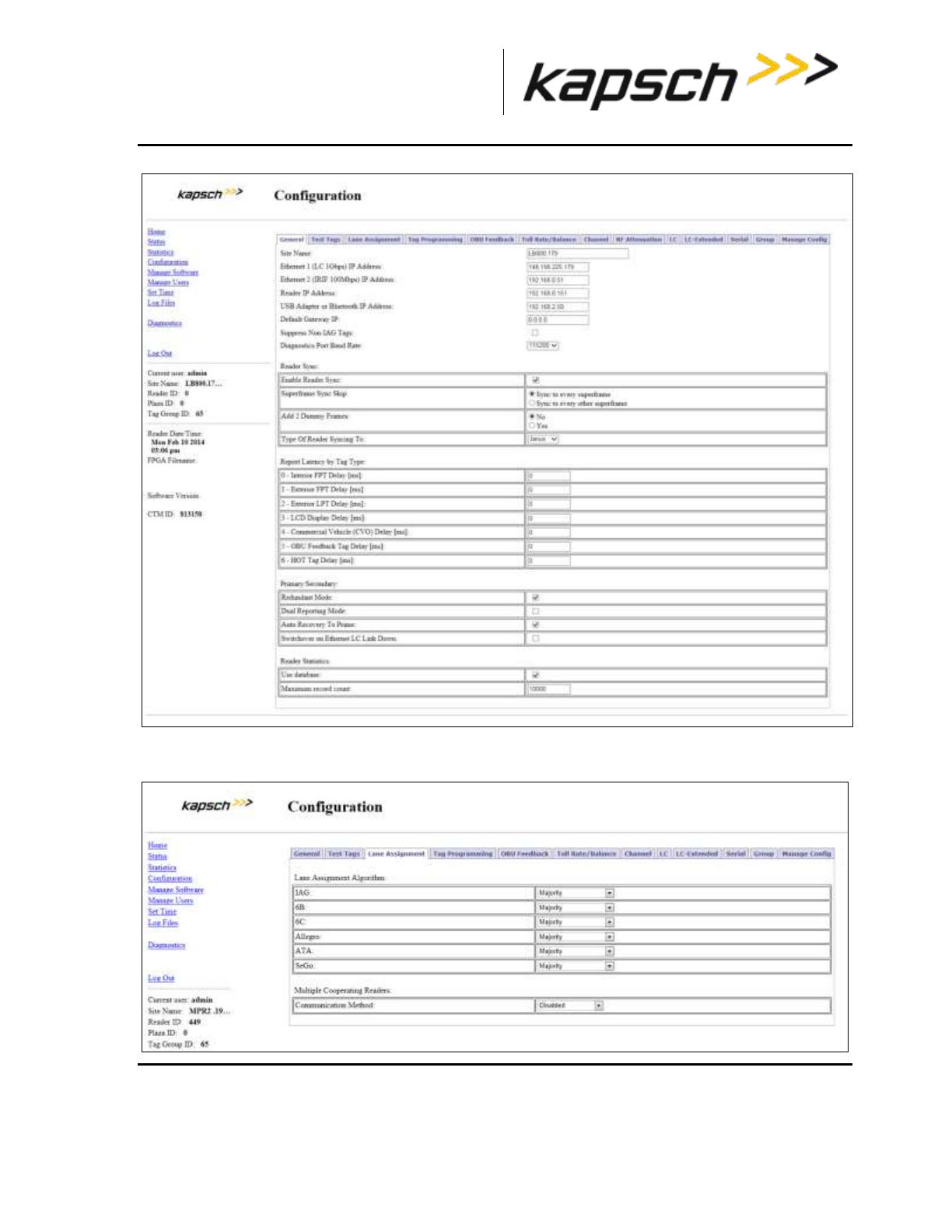
_
JANUS® Multi-Protocol Reader Ver. 2: Maintenance Instructions
Confidential UM 360463-202: A12 (Draft) Page 179 of 291
© Kapsch TrafficCom Canada Inc. 2013
These drawings and specifications contain confidential and proprietary information and are the property of Kapsch TrafficCom Canada Inc. and are issued in strict
confidence and will be kept confidential and used solely for the purpose intended and for no other purpose and shall not be transmitted, reproduced, copied, and/or
used as the basis for manufacture or sale of apparatus unless otherwise agreed to in writing by Kapsch TrafficCom Canada Inc.
FILE: MPR2_OPERATIONS_AND_MAINTENANCE-MANUAL_REV A12.DOCX 05/08/2014 11:24
Kapsch TrafficCom
1. Click the Lane Assignment tab.
Result: The following screen appears.

_
JANUS® Multi-Protocol Reader Ver. 2: Maintenance Instructions
Confidential UM 360463-202: A12 (Draft) Page 180 of 291
© Kapsch TrafficCom Canada Inc. 2013
These drawings and specifications contain confidential and proprietary information and are the property of Kapsch TrafficCom Canada Inc. and are issued in strict
confidence and will be kept confidential and used solely for the purpose intended and for no other purpose and shall not be transmitted, reproduced, copied, and/or
used as the basis for manufacture or sale of apparatus unless otherwise agreed to in writing by Kapsch TrafficCom Canada Inc.
FILE: MPR2_OPERATIONS_AND_MAINTENANCE-MANUAL_REV A12.DOCX 05/08/2014 11:24
Kapsch TrafficCom
2. Select either Majority or Interpolated from the drop-down box of the required protocol located in the
Lane Assignment Algorithm box.
Note: If Interpolated is selected from the drop-down box, channels with handshake counts that differ less
than the Handshake Equalization Ratio will be considered to have an equal handshake count since the
difference is not considered significant.
3. If Interpolated was selected in step 1, enter a percentage in the Handshake Equalization Ratio field.
4. Press Enter to accept the selections.
Configuring Voting Time
Manually setting a voting time gives a fixed voting time to each channel. Dynamic voting time allows
the Reader to calculate and base the voting time on the average capture zone span time (the time it
takes for an OBU to pass through a capture zone).
Manually set the voting time for a channel
Prerequisites: Connect the service laptop to the Reader configuration port to access the CTM web
interface. Refer to Connecting a service laptop to the Reader, page 40.
1. Select the Configuration link on the left side panel.
Result: The following screen appears.

_
JANUS® Multi-Protocol Reader Ver. 2: Maintenance Instructions
Confidential UM 360463-202: A12 (Draft) Page 181 of 291
© Kapsch TrafficCom Canada Inc. 2013
These drawings and specifications contain confidential and proprietary information and are the property of Kapsch TrafficCom Canada Inc. and are issued in strict
confidence and will be kept confidential and used solely for the purpose intended and for no other purpose and shall not be transmitted, reproduced, copied, and/or
used as the basis for manufacture or sale of apparatus unless otherwise agreed to in writing by Kapsch TrafficCom Canada Inc.
FILE: MPR2_OPERATIONS_AND_MAINTENANCE-MANUAL_REV A12.DOCX 05/08/2014 11:24
Kapsch TrafficCom
2. Click the Channel tab.
Result: The following screen appears.

_
JANUS® Multi-Protocol Reader Ver. 2: Maintenance Instructions
Confidential UM 360463-202: A12 (Draft) Page 182 of 291
© Kapsch TrafficCom Canada Inc. 2013
These drawings and specifications contain confidential and proprietary information and are the property of Kapsch TrafficCom Canada Inc. and are issued in strict
confidence and will be kept confidential and used solely for the purpose intended and for no other purpose and shall not be transmitted, reproduced, copied, and/or
used as the basis for manufacture or sale of apparatus unless otherwise agreed to in writing by Kapsch TrafficCom Canada Inc.
FILE: MPR2_OPERATIONS_AND_MAINTENANCE-MANUAL_REV A12.DOCX 05/08/2014 11:24
Kapsch TrafficCom
3. Select Disabled from the drop-down menu in the Dynamic Voting Control row .
4. Enter a voting time, in milliseconds, in the LPT/FME Voting Time field to set the voting time for LPT and
FME OBUs.
5. Enter a voting time, in milliseconds, in the Voting Time (all other tags) field to set the voting time for all
OBUs that are not LPT or FME.
6. If a voting time of 0 was entered in step 4 and step 5 and Dynamic Voting Control is disabled
(effectively disabling voting), click on the Group tab.
Result: The following screen appears.
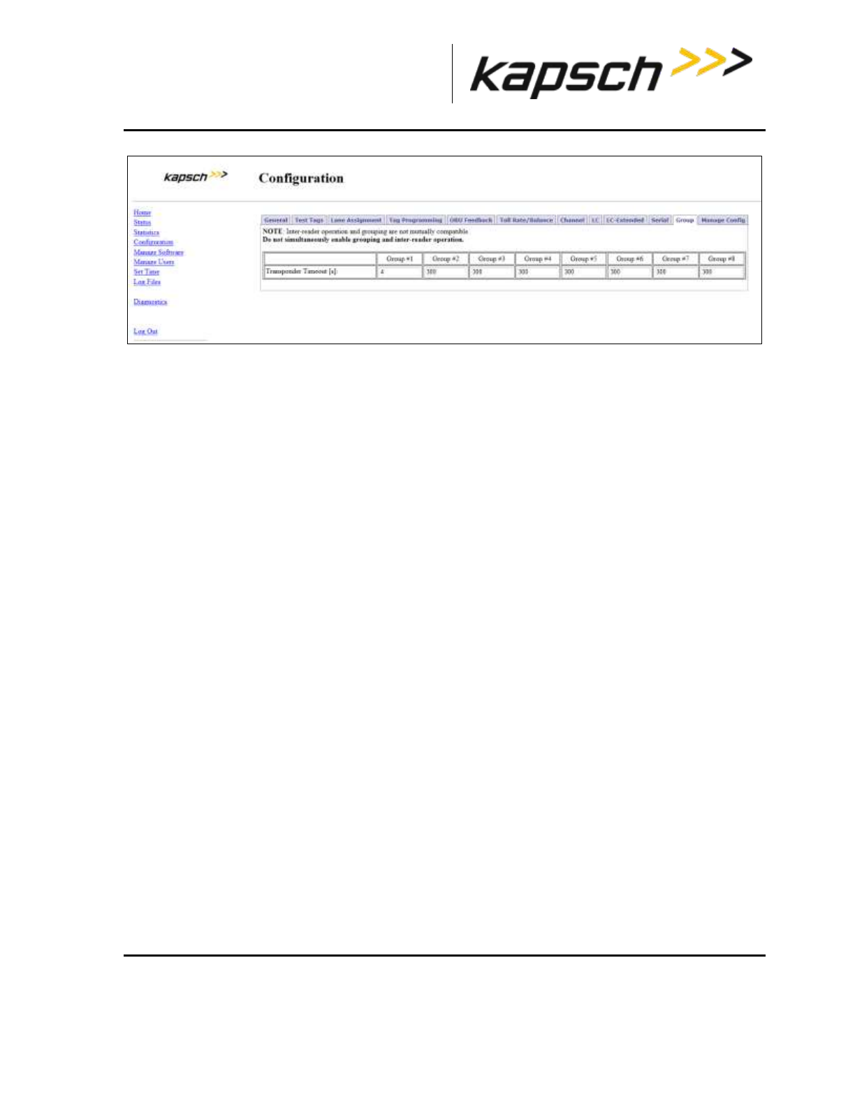
_
JANUS® Multi-Protocol Reader Ver. 2: Maintenance Instructions
Confidential UM 360463-202: A12 (Draft) Page 183 of 291
© Kapsch TrafficCom Canada Inc. 2013
These drawings and specifications contain confidential and proprietary information and are the property of Kapsch TrafficCom Canada Inc. and are issued in strict
confidence and will be kept confidential and used solely for the purpose intended and for no other purpose and shall not be transmitted, reproduced, copied, and/or
used as the basis for manufacture or sale of apparatus unless otherwise agreed to in writing by Kapsch TrafficCom Canada Inc.
FILE: MPR2_OPERATIONS_AND_MAINTENANCE-MANUAL_REV A12.DOCX 05/08/2014 11:24
Kapsch TrafficCom
7. Enter a time, in ms, in the Transponder Timeout field to set the maximum time that a Reader attempts
to program an OBU.
8. Repeat steps 4 through 7 to individually configure the other channels, or enter the number of a configured
channel in the field beside the Duplicate button on the Channel screen.
9. Click the Duplicate button to configure automatically the remaining channels.
Allowing the Reader to calculate the optimum voting time using Dynamic Voting Control
Prerequisites: Connect the service laptop to the Reader configuration port to access the CTM web
interface. Refer to Connecting a service laptop to the Reader, page 40.
1. Select the Configuration link on the left side panel.
Result: The following screen appears.
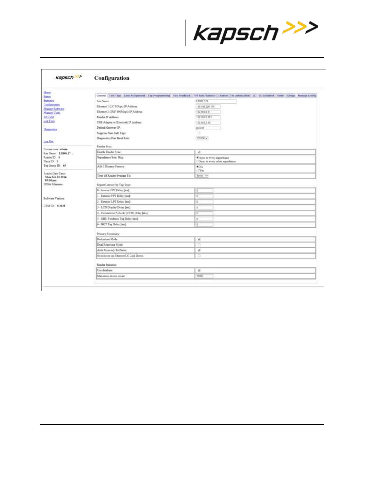
_
JANUS® Multi-Protocol Reader Ver. 2: Maintenance Instructions
Confidential UM 360463-202: A12 (Draft) Page 184 of 291
© Kapsch TrafficCom Canada Inc. 2013
These drawings and specifications contain confidential and proprietary information and are the property of Kapsch TrafficCom Canada Inc. and are issued in strict
confidence and will be kept confidential and used solely for the purpose intended and for no other purpose and shall not be transmitted, reproduced, copied, and/or
used as the basis for manufacture or sale of apparatus unless otherwise agreed to in writing by Kapsch TrafficCom Canada Inc.
FILE: MPR2_OPERATIONS_AND_MAINTENANCE-MANUAL_REV A12.DOCX 05/08/2014 11:24
Kapsch TrafficCom
2. Click the Channel tab.
Result: The following screen appears.
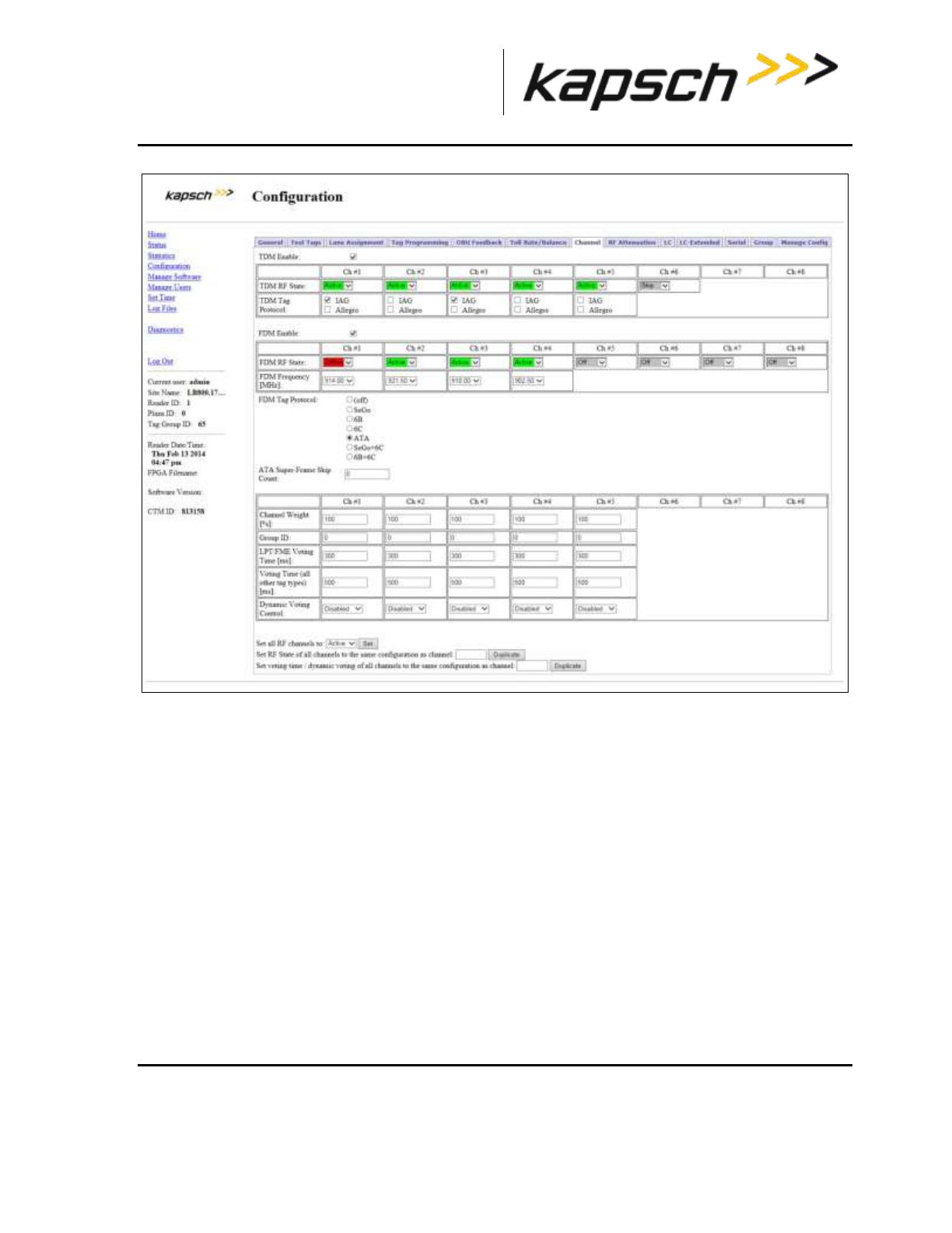
_
JANUS® Multi-Protocol Reader Ver. 2: Maintenance Instructions
Confidential UM 360463-202: A12 (Draft) Page 185 of 291
© Kapsch TrafficCom Canada Inc. 2013
These drawings and specifications contain confidential and proprietary information and are the property of Kapsch TrafficCom Canada Inc. and are issued in strict
confidence and will be kept confidential and used solely for the purpose intended and for no other purpose and shall not be transmitted, reproduced, copied, and/or
used as the basis for manufacture or sale of apparatus unless otherwise agreed to in writing by Kapsch TrafficCom Canada Inc.
FILE: MPR2_OPERATIONS_AND_MAINTENANCE-MANUAL_REV A12.DOCX 05/08/2014 11:24
Kapsch TrafficCom
2. Set the Dynamic Voting Control to Reader to allow the Reader to automatically set the voting time by
calculating the average capture zone span time.
3. Press Enter.
4. Enter a sample size in the Dynamic Voting Sample Size field. This is the number of previous
transactions the Reader includes when calculating the average capture zone span time.
Note: The Reader calculates the capture zone span time after each OBU transaction. The Reader will
not update the Dynamic Voting Time unless the capture zone span time changes more than the Dynamic
Voting Threshold percentage.
5. Enter a percentage in the Dynamic Voting Threshold field.
6. Press Enter or click outside the fields.
Result: The following screen appears.

_
JANUS® Multi-Protocol Reader Ver. 2: Maintenance Instructions
Confidential UM 360463-202: A12 (Draft) Page 186 of 291
© Kapsch TrafficCom Canada Inc. 2013
These drawings and specifications contain confidential and proprietary information and are the property of Kapsch TrafficCom Canada Inc. and are issued in strict
confidence and will be kept confidential and used solely for the purpose intended and for no other purpose and shall not be transmitted, reproduced, copied, and/or
used as the basis for manufacture or sale of apparatus unless otherwise agreed to in writing by Kapsch TrafficCom Canada Inc.
FILE: MPR2_OPERATIONS_AND_MAINTENANCE-MANUAL_REV A12.DOCX 05/08/2014 11:24
Kapsch TrafficCom
Configuring Channel Weight for straddle antennas
The handshake count of straddle channels (channels 2 and 4 in Figure 5-14) typically have less weight
assigned to them than non-straddle channels (channels 1, 3, and 5 in Figure 5-14).
Prerequisites: Connect the service laptop to the Reader configuration port to access the CTM web
interface. Refer to Connecting a service laptop to the Reader, page 40.
1. Select the Configuration link on the left side panel.
Result: The following screen appears.

_
JANUS® Multi-Protocol Reader Ver. 2: Maintenance Instructions
Confidential UM 360463-202: A12 (Draft) Page 187 of 291
© Kapsch TrafficCom Canada Inc. 2013
These drawings and specifications contain confidential and proprietary information and are the property of Kapsch TrafficCom Canada Inc. and are issued in strict
confidence and will be kept confidential and used solely for the purpose intended and for no other purpose and shall not be transmitted, reproduced, copied, and/or
used as the basis for manufacture or sale of apparatus unless otherwise agreed to in writing by Kapsch TrafficCom Canada Inc.
FILE: MPR2_OPERATIONS_AND_MAINTENANCE-MANUAL_REV A12.DOCX 05/08/2014 11:24
Kapsch TrafficCom
2. Click the Channel tab.
Result: The following screen appears.

_
JANUS® Multi-Protocol Reader Ver. 2: Maintenance Instructions
Confidential UM 360463-202: A12 (Draft) Page 188 of 291
© Kapsch TrafficCom Canada Inc. 2013
These drawings and specifications contain confidential and proprietary information and are the property of Kapsch TrafficCom Canada Inc. and are issued in strict
confidence and will be kept confidential and used solely for the purpose intended and for no other purpose and shall not be transmitted, reproduced, copied, and/or
used as the basis for manufacture or sale of apparatus unless otherwise agreed to in writing by Kapsch TrafficCom Canada Inc.
FILE: MPR2_OPERATIONS_AND_MAINTENANCE-MANUAL_REV A12.DOCX 05/08/2014 11:24
Kapsch TrafficCom
3. Enter a percentage in the Channel Weight field for each channel.
Example: A channel weight of 100% means the full handshake count is considered at voting time, while a
channel weight of 50% means only half the handshake count is considered at voting time.
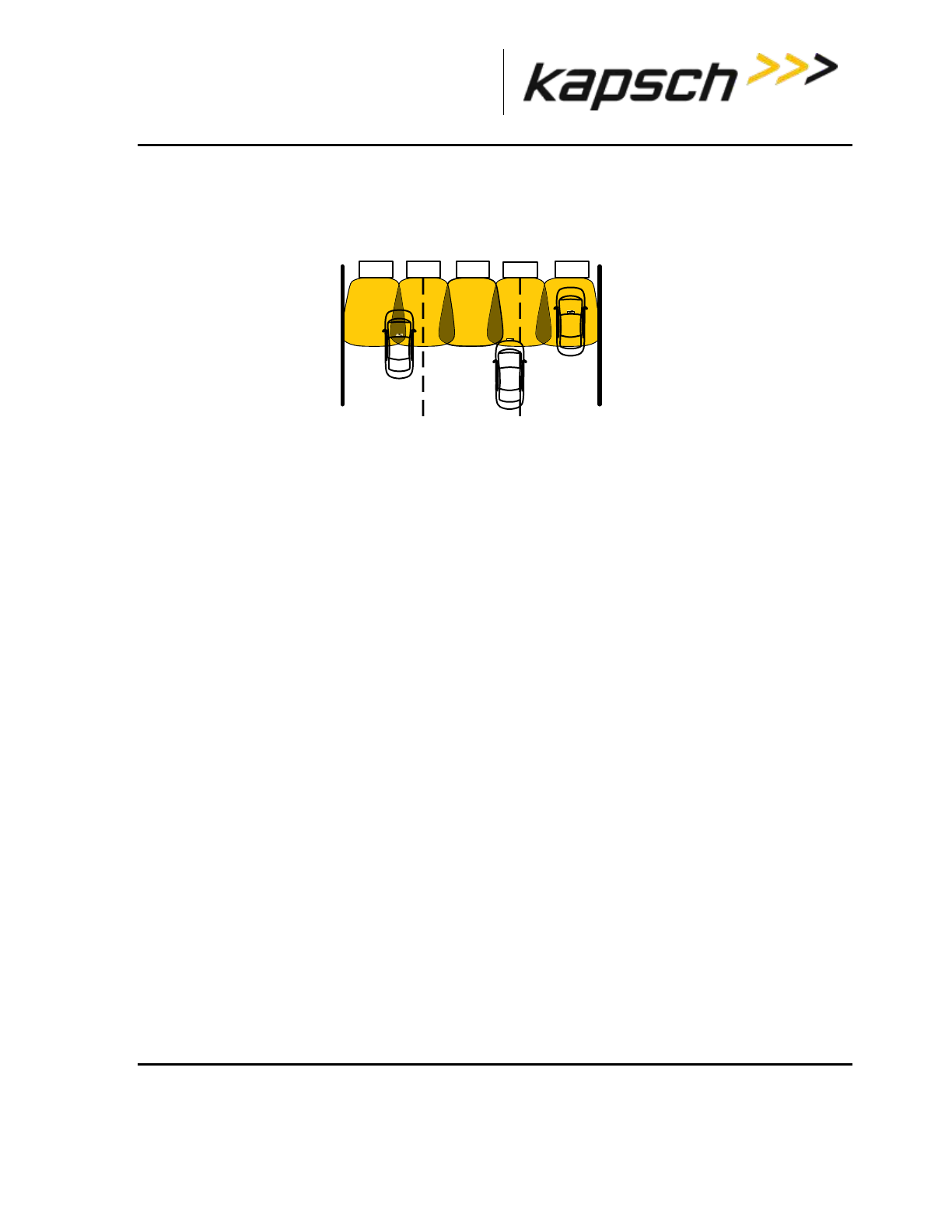
_
JANUS® Multi-Protocol Reader Ver. 2: Maintenance Instructions
Confidential UM 360463-202: A12 (Draft) Page 189 of 291
© Kapsch TrafficCom Canada Inc. 2013
These drawings and specifications contain confidential and proprietary information and are the property of Kapsch TrafficCom Canada Inc. and are issued in strict
confidence and will be kept confidential and used solely for the purpose intended and for no other purpose and shall not be transmitted, reproduced, copied, and/or
used as the basis for manufacture or sale of apparatus unless otherwise agreed to in writing by Kapsch TrafficCom Canada Inc.
FILE: MPR2_OPERATIONS_AND_MAINTENANCE-MANUAL_REV A12.DOCX 05/08/2014 11:24
Kapsch TrafficCom
Figure 5-14: Three Wide ORT lanes with two straddle antennas
Ch 1 Ch 2 Ch 3 Ch 4 Ch 5
Wide ORT lanes
lane 1 lane 2 lane 3

_
JANUS® Multi-Protocol Reader Ver. 2: Maintenance Instructions
Confidential UM 360463-202: A12 (Draft) Page 190 of 291
© Kapsch TrafficCom Canada Inc. 2013
These drawings and specifications contain confidential and proprietary information and are the property of Kapsch TrafficCom Canada Inc. and are issued in strict
confidence and will be kept confidential and used solely for the purpose intended and for no other purpose and shall not be transmitted, reproduced, copied, and/or
used as the basis for manufacture or sale of apparatus unless otherwise agreed to in writing by Kapsch TrafficCom Canada Inc.
FILE: MPR2_OPERATIONS_AND_MAINTENANCE-MANUAL_REV A12.DOCX 05/08/2014 11:24
Kapsch TrafficCom
6. TROUBLESHOOTING AND TESTING
Troubleshooting Methodology
Troubleshooting trees are provided for resolving the most common Reader issues. A Test and
Replace methodology is used for servicing the Reader system. The general steps are:
1. Test all symptoms that may have attributed to the reported system fault. Use the following suggestions to
reveal faults:
Examine the Reader status on the Reader browser STATUS page (see Reader status,
page 46).
Examine the RF channel statistics (page 53).
Examine the trouble log files for any reported issues with the Reader (page 141).
Observe the status LEDs on the Reader front panel (see LED Status, page 192).
Replace a suspected faulty component.
Continue with symptom testing and component replacement until there are no fault symptoms.
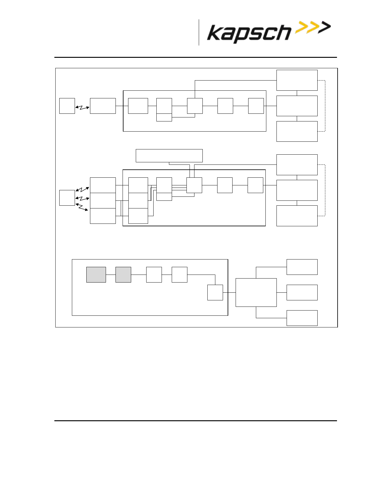
_
JANUS® Multi-Protocol Reader Ver. 2: Maintenance Instructions
Confidential UM 360463-202: A12 (Draft) Page 191 of 291
© Kapsch TrafficCom Canada Inc. 2013
These drawings and specifications contain confidential and proprietary information and are the property of Kapsch TrafficCom Canada Inc. and are issued in strict
confidence and will be kept confidential and used solely for the purpose intended and for no other purpose and shall not be transmitted, reproduced, copied, and/or
used as the basis for manufacture or sale of apparatus unless otherwise agreed to in writing by Kapsch TrafficCom Canada Inc.
FILE: MPR2_OPERATIONS_AND_MAINTENANCE-MANUAL_REV A12.DOCX 05/08/2014 11:24
Kapsch TrafficCom
Reader components in sync signal generation
path. After sync signal detection by the CTM, the
shaded components are in the sync usage path.
CTM LANE
CONTROLLER
HOST
COMPUTER
Signal Flow Diagram:
Tag Transaction in one dedicated lane
MRFMSANTENNATAG DSM DSM LPM
Reader components in transaction signal path.
CTM
Signal Flow Diagram:
Tag Transaction in ORT
MRFMS ANTENNA
TAG
DSM LPM
Reader components in
transaction signal path.
MRFMS
MRFMS
ANTENNA
ANTENNA
CTM
Signal Flow Diagram:
Synchronization
MRFMS DSM DSM
SPM STAR SYNC HUB
(TERMINAL
BLOCK)
READER 2
READER 3
READER 4
INTERNET LAN
LANE
CONTROLLER
HOST
COMPUTER
INTERNET LAN
CFM
DSM
CFM
INTER-READER NETWORK
(if voting on lane assignment)
Figure 6-1: Signal Flow Diagrams

_
JANUS® Multi-Protocol Reader Ver. 2: Maintenance Instructions
Confidential UM 360463-202: A12 (Draft) Page 192 of 291
© Kapsch TrafficCom Canada Inc. 2013
These drawings and specifications contain confidential and proprietary information and are the property of Kapsch TrafficCom Canada Inc. and are issued in strict
confidence and will be kept confidential and used solely for the purpose intended and for no other purpose and shall not be transmitted, reproduced, copied, and/or
used as the basis for manufacture or sale of apparatus unless otherwise agreed to in writing by Kapsch TrafficCom Canada Inc.
FILE: MPR2_OPERATIONS_AND_MAINTENANCE-MANUAL_REV A12.DOCX 05/08/2014 11:24
Kapsch TrafficCom
LED Statuses
The following table gives an overview of all the LEDs on the Reader. See the Troubleshooting Trees
beginning on page 194 to resolve any issues.
Table 6-1: CTM LED states explained
CTM LEDs
LED
State
Meaning
CGC
solid green
CGC is functional
solid red
CGC has failed
MC
solid green
MC is functional
solid red
MC has failed
SYNC
solid green
Reader is synchronized
flashing red
Reader out of sync, or,
No activity on the Rx port on the terminal block of the
SPM (R+ and R- on the connector).
another Reader in sync network is stuck in the busy
state
flashing green/orange
Reader is out of sync and attempting recovery
off
Synchronization is disabled
ACTIVE
solid green
the CTM is active and in control. This indicates if the
primary or secondary side is active.
solid red
the CTM is not active
POWER
solid green
CTM is receiving power from PSM
off
CTM is not receiving power from PSM, or,
CTM reset switch is OFF
ACTIVITY
(Ethernet 1)
flashing green
data is being transmitted via the Ethernet 1 port
off
data is not being transmitted via the Ethernet 1 port
ACTIVITY
(Ethernet 2)
flashing green
data is being transmitted via the Ethernet 2 port
off
data is not being transmitted via the Ethernet 2 port

_
JANUS® Multi-Protocol Reader Ver. 2: Maintenance Instructions
Confidential UM 360463-202: A12 (Draft) Page 193 of 291
© Kapsch TrafficCom Canada Inc. 2013
These drawings and specifications contain confidential and proprietary information and are the property of Kapsch TrafficCom Canada Inc. and are issued in strict
confidence and will be kept confidential and used solely for the purpose intended and for no other purpose and shall not be transmitted, reproduced, copied, and/or
used as the basis for manufacture or sale of apparatus unless otherwise agreed to in writing by Kapsch TrafficCom Canada Inc.
FILE: MPR2_OPERATIONS_AND_MAINTENANCE-MANUAL_REV A12.DOCX 05/08/2014 11:24
Kapsch TrafficCom
Table 6-2: PSM LED states explained
PSM LED
LED
State
Meaning
+15 STATUS
solid green
PSM is supplying +15VDC via DSM
off
PSM is not supplying +15VDC
+5 STATUS
solid green
PSM is supplying +5VDC via DSM
off
PSM is not supplying +5VDC
Table 6-3: MRFM-S LED states explained
MRFM-S LED
LED
State
Meaning
DATA
solid green
MRFM-S is functional
off
MRFM-S is not enabled
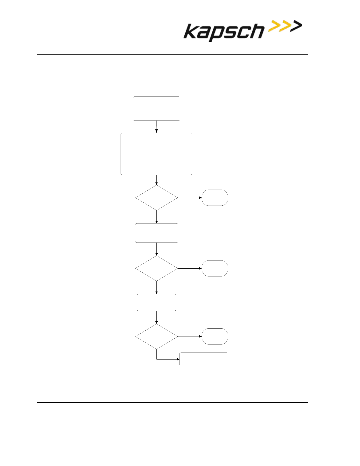
_
JANUS® Multi-Protocol Reader Ver. 2: Maintenance Instructions
Confidential UM 360463-202: A12 (Draft) Page 194 of 291
© Kapsch TrafficCom Canada Inc. 2013
These drawings and specifications contain confidential and proprietary information and are the property of Kapsch TrafficCom Canada Inc. and are issued in strict
confidence and will be kept confidential and used solely for the purpose intended and for no other purpose and shall not be transmitted, reproduced, copied, and/or
used as the basis for manufacture or sale of apparatus unless otherwise agreed to in writing by Kapsch TrafficCom Canada Inc.
FILE: MPR2_OPERATIONS_AND_MAINTENANCE-MANUAL_REV A12.DOCX 05/08/2014 11:24
Kapsch TrafficCom
Troubleshooting tree: LC Ethernet 1 Port communications not working
START
Symptom:
Status page shows LC
Ethernet link is Down
Test the CTM ETHERNET
1 port
LC Ethernet link
status Enabled?
Contact Kapsch Service for
assistance
Replace the CTM
LC Ethernet link
status Enabled?
Verify ESM tests OK.
Verify Ethernet cable connections
between the reader, Ethernet switch (if
present), and Lane Controller pass a
continuity test for open, high
impedance, and short circuit conditions.
Verify LC Ethernet communication is
configured correctly.
LC Ethernet
link is
functional
LC Ethernet
link is
functional
No
Yes
No
Yes
LC Ethernet link
status Enabled?
LC Ethernet
link is
functional
No
Yes
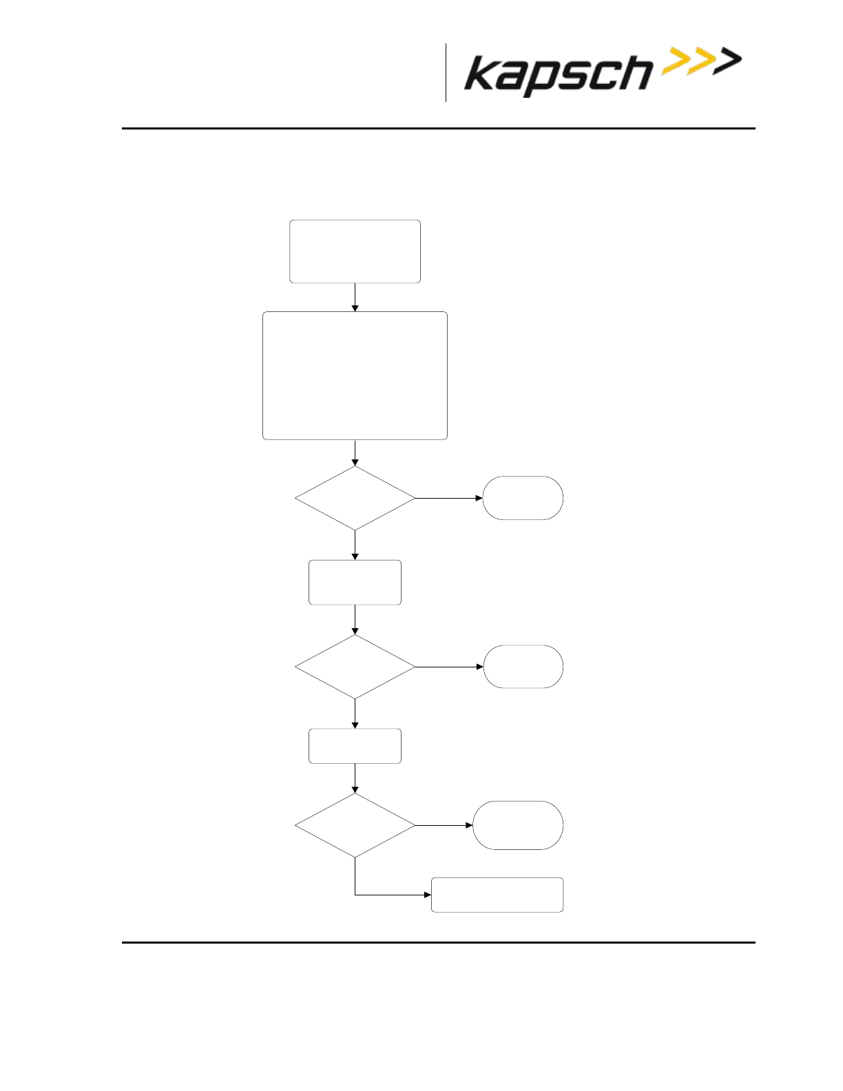
_
JANUS® Multi-Protocol Reader Ver. 2: Maintenance Instructions
Confidential UM 360463-202: A12 (Draft) Page 195 of 291
© Kapsch TrafficCom Canada Inc. 2013
These drawings and specifications contain confidential and proprietary information and are the property of Kapsch TrafficCom Canada Inc. and are issued in strict
confidence and will be kept confidential and used solely for the purpose intended and for no other purpose and shall not be transmitted, reproduced, copied, and/or
used as the basis for manufacture or sale of apparatus unless otherwise agreed to in writing by Kapsch TrafficCom Canada Inc.
FILE: MPR2_OPERATIONS_AND_MAINTENANCE-MANUAL_REV A12.DOCX 05/08/2014 11:24
Kapsch TrafficCom
Troubleshooting tree: Ethernet 2 Port communications not working
START
Symptom:
Status page shows Inter-
Reader Ethernet link is
Down
IR Ethernet link
status is Enabled?
IR Ethernet link
is functional
Test the CTM
Ethernet 2 port
IR Ethernet link
status is Enabled?
Contact Kapsch Service
for assistance
Yes
No
Replace the CTM
IR Ethernet link
status is Enabled?
Verify Ethernet switch (if present)
tests OK.
Verify Ethernet cable connections
between the reader, Ethernet switch
(if present), and other IR network
Readers pass a continuity test for
open, high impedance, and short
circuit conditions.
Verify IR network is configured
correctly.
Yes
No
Yes
No
IR Ethernet link
is functional
IR Ethernet link is
functional
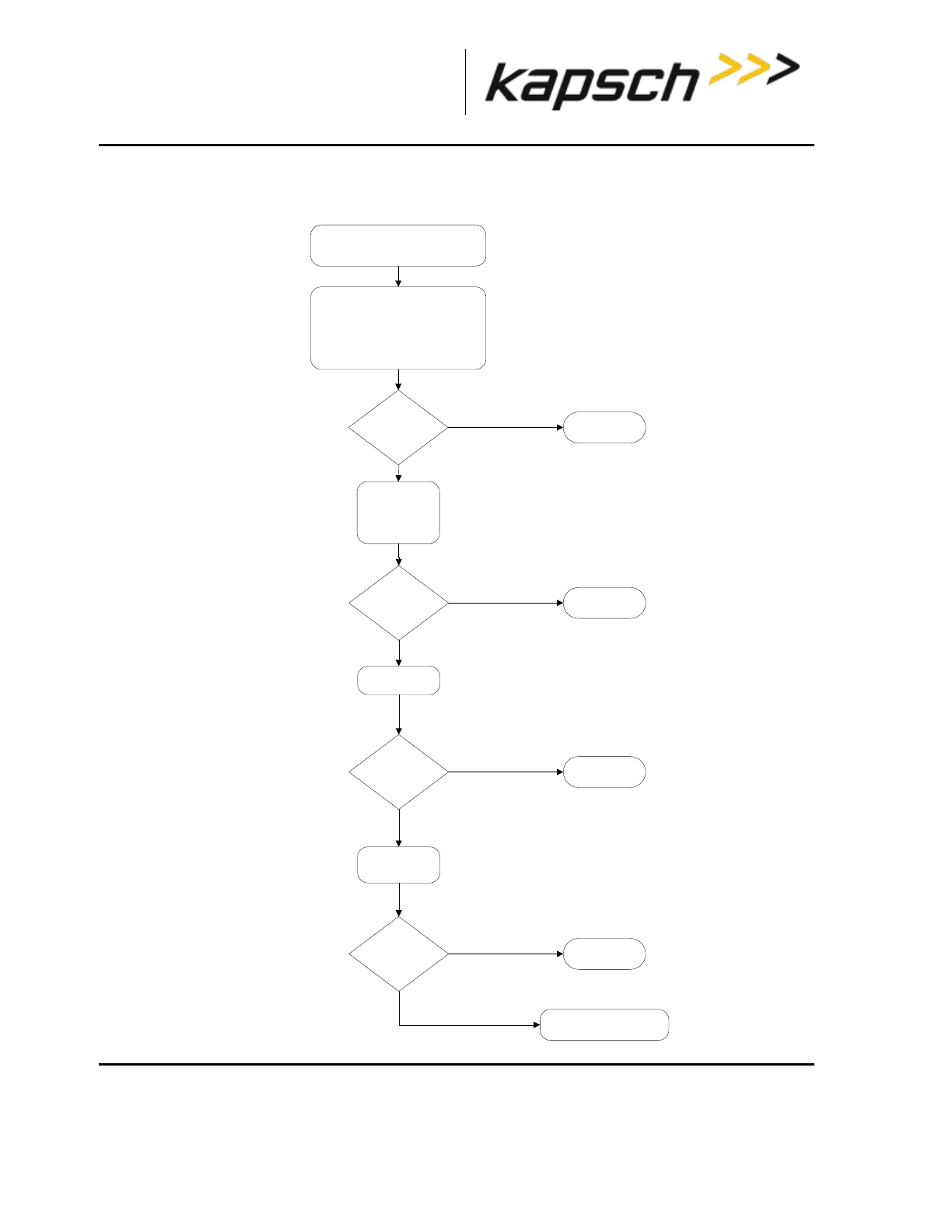
_
JANUS® Multi-Protocol Reader Ver. 2: Maintenance Instructions
Confidential UM 360463-202: A12 (Draft) Page 196 of 291
© Kapsch TrafficCom Canada Inc. 2013
These drawings and specifications contain confidential and proprietary information and are the property of Kapsch TrafficCom Canada Inc. and are issued in strict
confidence and will be kept confidential and used solely for the purpose intended and for no other purpose and shall not be transmitted, reproduced, copied, and/or
used as the basis for manufacture or sale of apparatus unless otherwise agreed to in writing by Kapsch TrafficCom Canada Inc.
FILE: MPR2_OPERATIONS_AND_MAINTENANCE-MANUAL_REV A12.DOCX 05/08/2014 11:24
Kapsch TrafficCom
Troubleshooting tree: LPM Serial Port communications not working
Start
Symptom:
Status page shows LC Serial Link is down
Verify serial cable connections from
the reader to the Lane Controller
pass a continuity test for open
circuit, high impedance, or short
circuit conditions.
Verify LC serial communication
settings are configured correctly
LC Serial link
status displays
Enabled?
LC Serial link is
functional
Test the LPM
board serial COM
port(s)
LC Serial link is
functional
Replace the CTM
LC Serial link is
functional
Replace the LPM
LC Serial link is
functional
Contact Kapsch Service for
assistance
LC Serial link
status displays
Enabled?
LC Serial link
status displays
Enabled?
LC Serial link
status displays
Enabled?
Yes
No
Yes
No
Yes
No
Yes
No
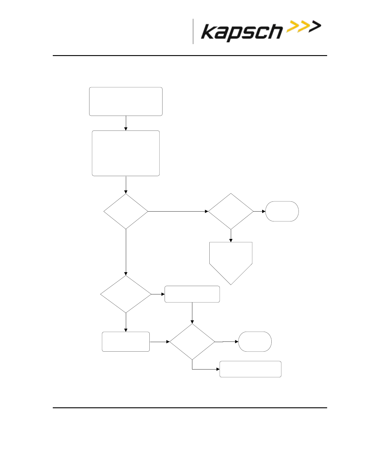
_
JANUS® Multi-Protocol Reader Ver. 2: Maintenance Instructions
Confidential UM 360463-202: A12 (Draft) Page 197 of 291
© Kapsch TrafficCom Canada Inc. 2013
These drawings and specifications contain confidential and proprietary information and are the property of Kapsch TrafficCom Canada Inc. and are issued in strict
confidence and will be kept confidential and used solely for the purpose intended and for no other purpose and shall not be transmitted, reproduced, copied, and/or
used as the basis for manufacture or sale of apparatus unless otherwise agreed to in writing by Kapsch TrafficCom Canada Inc.
FILE: MPR2_OPERATIONS_AND_MAINTENANCE-MANUAL_REV A12.DOCX 05/08/2014 11:24
Kapsch TrafficCom
Troubleshooting tree: MRFM-S not working
START
Symptom:
MRFM-S LED is OFF
MRFM-S
DATA LED
OFF?
Contact Kapsch Service for
assistance
Replace the MRFM-S
CTM ACTIVE
LED ON?
MRFM-S
DATA LED solid
green?
Verify antenna is
undamaged.
Verify all cable connections
from antenna to RF
module.
Verify RF channels are set
to Active.
Perform Sync
Troubleshooting
No
YesNo
Yes
Yes
No
Replace the CTM
Yes
No
MRFM-S is
functional
MRFM-S DATA
LED solid green?
MRFM-S is
functional
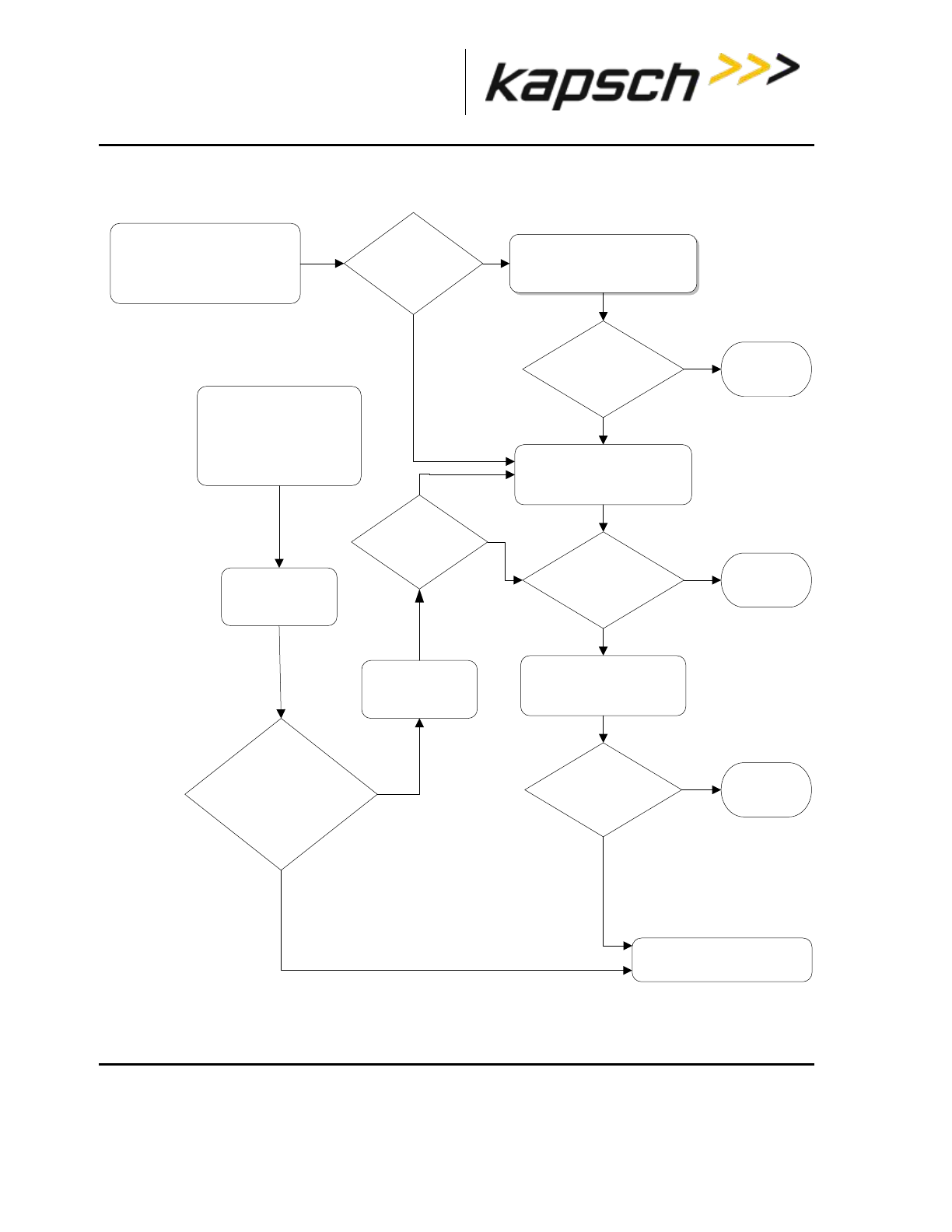
_
JANUS® Multi-Protocol Reader Ver. 2: Maintenance Instructions
Confidential UM 360463-202: A12 (Draft) Page 198 of 291
© Kapsch TrafficCom Canada Inc. 2013
These drawings and specifications contain confidential and proprietary information and are the property of Kapsch TrafficCom Canada Inc. and are issued in strict
confidence and will be kept confidential and used solely for the purpose intended and for no other purpose and shall not be transmitted, reproduced, copied, and/or
used as the basis for manufacture or sale of apparatus unless otherwise agreed to in writing by Kapsch TrafficCom Canada Inc.
FILE: MPR2_OPERATIONS_AND_MAINTENANCE-MANUAL_REV A12.DOCX 05/08/2014 11:24
Kapsch TrafficCom
Troubleshooting tree: Synchronization not working
START
Symptom A:
Sync Indicator is off or flashing
red
Is Sync disabled?
Enable Sync from the Reader
browser interface
Is SYNC LED
solid green?
Test the SPM and CTM
replace as required
Is SYNC LED
solid green?
Sync is
functional
Are any “reader
SYNC lost” messages in
recent trouble<date> log
file?
Reader is
attempting Sync
Recovery
Contact Kapsch Service
for assistance
No
Yes
No
Test wiring to sync hub,
repair as required
Is SYNC LED
solid green?
START
Symptom B:
Sync Indicator is flashing
intermittently GREEN and
ORANGE
Sync is
functional
Sync is
functional
Yes
No
Yes
No
Yes
No
Yes
No
Verify channels
config. on both
CTMs match
Are CTMs sync’d
No
Yes

_
JANUS® Multi-Protocol Reader Ver. 2: Maintenance Instructions
Confidential UM 360463-202: A12 (Draft) Page 199 of 291
© Kapsch TrafficCom Canada Inc. 2013
These drawings and specifications contain confidential and proprietary information and are the property of Kapsch TrafficCom Canada Inc. and are issued in strict
confidence and will be kept confidential and used solely for the purpose intended and for no other purpose and shall not be transmitted, reproduced, copied, and/or
used as the basis for manufacture or sale of apparatus unless otherwise agreed to in writing by Kapsch TrafficCom Canada Inc.
FILE: MPR2_OPERATIONS_AND_MAINTENANCE-MANUAL_REV A12.DOCX 05/08/2014 11:24
Kapsch TrafficCom
Constant busy state on sync bus
A Reader that erroneously holds the sync bus in a BUSY state causes all other Readers connected to
the bus to time-out while waiting for the READY state. As a result, all of their CTM SYNC LEDs will be
flashing red. Disconnect each Reader one at a time from the sync hub until the fault clears then
reconnect each Reader in the order of removal until the fault reappears. Service each faulty Reader.
Sync board Failure Indicator for incomplete cable connections
The CTM SYNC LED will flash steadily red if there is no activity on the Rx port on the terminal block of
the SPM (R+ and R- on the connector). If both transmit and receive connections are cut off from the
sync hub the indicator will flash red. If only the transmit connection is disconnected and there are other
Readers in the synchronization network, the CTM SYNC LED stays green.
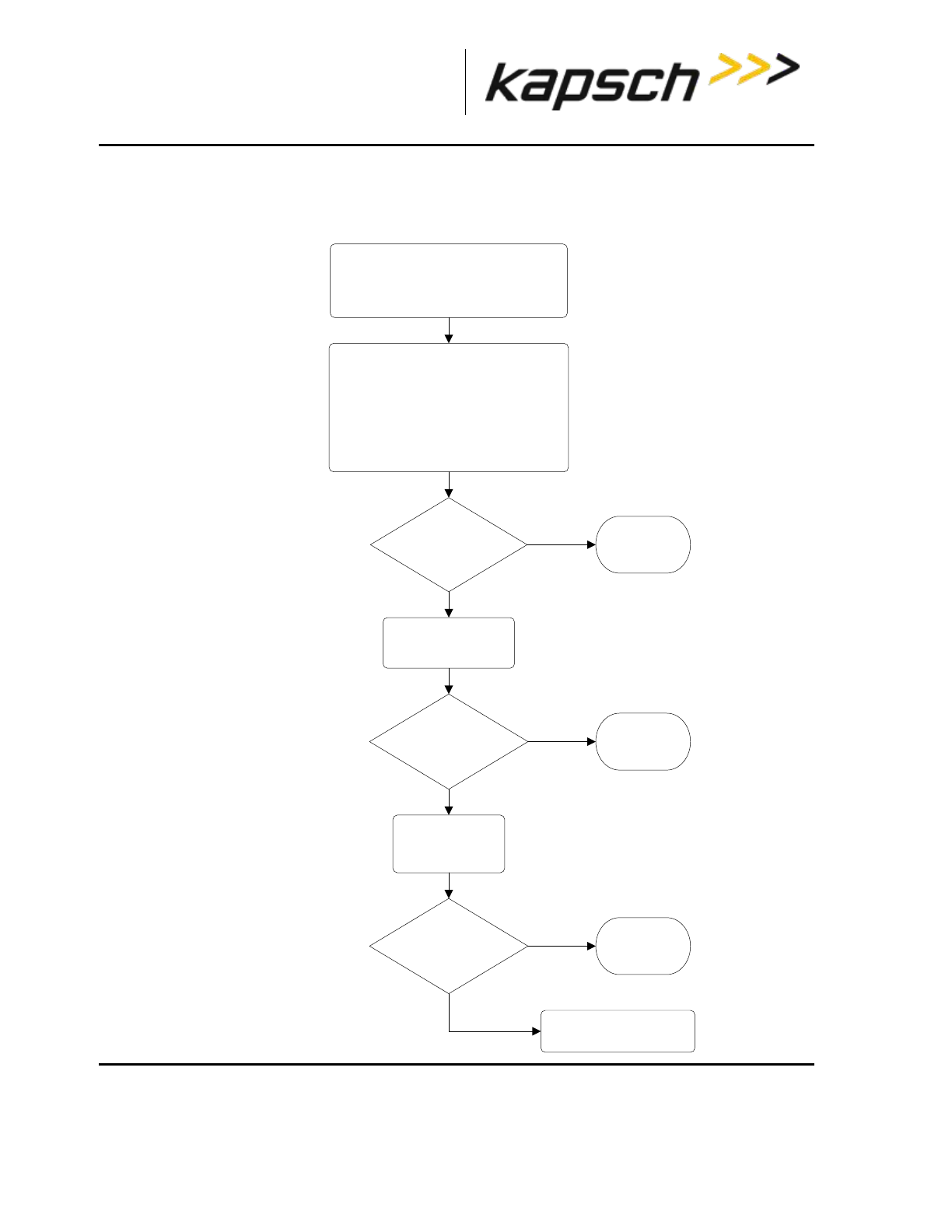
_
JANUS® Multi-Protocol Reader Ver. 2: Maintenance Instructions
Confidential UM 360463-202: A12 (Draft) Page 200 of 291
© Kapsch TrafficCom Canada Inc. 2013
These drawings and specifications contain confidential and proprietary information and are the property of Kapsch TrafficCom Canada Inc. and are issued in strict
confidence and will be kept confidential and used solely for the purpose intended and for no other purpose and shall not be transmitted, reproduced, copied, and/or
used as the basis for manufacture or sale of apparatus unless otherwise agreed to in writing by Kapsch TrafficCom Canada Inc.
FILE: MPR2_OPERATIONS_AND_MAINTENANCE-MANUAL_REV A12.DOCX 05/08/2014 11:24
Kapsch TrafficCom
Troubleshooting tree: Reader does not automatically switch back to Primary
side after fault recovery
START
Symptom:
Reader stays in Secondary side without
auto recovering to Primary side
All Primary STATUS
LEDs solid green?
Contact Kapsch Service
for assistance
Yes
No
Replace Primary
CTM
All Primary STATUS
LEDs solid green?
Reboot Primary CTM
All Primary STATUS
LEDs solid green?
Verify Primary PMS +5 and +15 LEDs
are solid green.
Verify correct configuration file is
loaded.
Verify Auto Recovery to Prime is
enabled.
Verify SPM mode switch is set to Auto
Yes
No
Yes
No
Primary side
is active
Primary side
is active
Primary side
is active

_
JANUS® Multi-Protocol Reader Ver. 2: Maintenance Instructions
Confidential UM 360463-202: A12 (Draft) Page 201 of 291
© Kapsch TrafficCom Canada Inc. 2013
These drawings and specifications contain confidential and proprietary information and are the property of Kapsch TrafficCom Canada Inc. and are issued in strict
confidence and will be kept confidential and used solely for the purpose intended and for no other purpose and shall not be transmitted, reproduced, copied, and/or
used as the basis for manufacture or sale of apparatus unless otherwise agreed to in writing by Kapsch TrafficCom Canada Inc.
FILE: MPR2_OPERATIONS_AND_MAINTENANCE-MANUAL_REV A12.DOCX 05/08/2014 11:24
Kapsch TrafficCom
Troubleshooting tree: Simultaneous faults on Primary and Secondary CTMs
Simultaneous
faults resolved
START Symptom:
Both CTM MC and/or CGC2 LEDs are solid red
Switchover on Serial
Link down Enabled?
Simultaneous
faults resolved
Contact Kapsch
Service for
assistance
Yes
No
Check if the Lane Controller Ethernet Links are Down on
the Status page. If the LC Ethernet links are down,
check the LC Ethernet server, connections and cables to
primary and secondary sides of the Reader.
Switchover on Ethernet
LC link down enabled?
Check if the Lane Controller Serial Links are Down on
the Status page. Check that the serial connections to the
LC are good for both Primary and Secondary LPMs.
Both MC and/or CGC2
LEDs solid red
Simultaneous
faults resolved
Both MC and/or CGC2
LEDs solid red
Switchover on
Inter-Reader Ethernet Link
down Enabled?
Check if the Inter-Reader Ethernet Links are Down on the Status
page. If the Inter-Reader links are down, check the IR Ethernet
cables attached to the front panel, as well as the configuration of the
adjacent reader (i.e., confirm it is enabled for Inter-Reader and the
configuration is correct).
Both MC and/or CGC2
LEDs solid red
Was a lightning
strike possible at the time
the fault first
occurred?
Yes No
Ensure that the Reader rack is grounded properly.
Check, and replace if necessary, all lightning /surge
protectors.
If simultaneous faults persist, replace Primary CTM. If
Primary CTM recovers, replace Secondary CTM.
Both MC and/or CGC2
LEDs solid red Simultaneous
faults resolved
Yes No
Yes No
Yes No
Yes
No
Yes
No
Yes
No

_
JANUS® Multi-Protocol Reader Ver. 2: Maintenance Instructions
Confidential UM 360463-202: A12 (Draft) Page 202 of 291
© Kapsch TrafficCom Canada Inc. 2013
These drawings and specifications contain confidential and proprietary information and are the property of Kapsch TrafficCom Canada Inc. and are issued in strict
confidence and will be kept confidential and used solely for the purpose intended and for no other purpose and shall not be transmitted, reproduced, copied, and/or
used as the basis for manufacture or sale of apparatus unless otherwise agreed to in writing by Kapsch TrafficCom Canada Inc.
FILE: MPR2_OPERATIONS_AND_MAINTENANCE-MANUAL_REV A12.DOCX 05/08/2014 11:24
Kapsch TrafficCom
Identifying failures on the primary and/or secondary side
Primary and/or Secondary side failure is indicated by any of the following conditions:
Ethernet LC link down, as indicated on the Reader browser Status page.
Ethernet IR network link down, as indicated on the Reader browser Status page.
Primary CTM MC or CGC LEDs are red
Serial LC link down, as indicated on the Reader browser STATUS page
Primary side failure is indicated by any of the following conditions
SPM switch is in PRIMARY position: primary CTM ACTIVE LED is red
SPM switch is in AUTO position: primary CTM ACTIVE LED is red
Secondary side failure is indicated by any of the following conditions:
SPM switch in any position: secondary MC or CGC LEDs are red
SPM switch is in SECONDARY position: secondary CTM ACTIVE LED is red
SPM switch is in AUTO position: primary CTM ACTIVE LED is red and secondary CTM ACTIVE
LED is red.
Events that cause an automatic switchover
Table 6-4 outlines the situations that can cause an automatic switchover and what settings need to be
configured for the trigger to be enabled.
Table 6-4: Switchover triggers
Event
Cause
Enabling
Failed CGC Health
The Reader continuously monitors the CGC
health and forces a switchover if health fails.
Automatic
Failed Serial Lane
Controller Link
The Reader forces a switchover when an
enabled serial link from the LPM to the LC
has been interrupted. Usually a downed link
is due to external conditions.
Only the lack of OBU transactions in outgoing
messages to the LC allows a downed link to
be detected. To detect serial cable issues in
the absence of OBU transactions, the
operator must enable Heartbeat messages
Must enable Switchover on
Serial Link Down from
General tab on
Configuration page
Must set LC Retry Timeout
from Serial tab on
Configuration page
Set Heartbeat messages from
LC tab on Configuration
page

_
JANUS® Multi-Protocol Reader Ver. 2: Maintenance Instructions
Confidential UM 360463-202: A12 (Draft) Page 203 of 291
© Kapsch TrafficCom Canada Inc. 2013
These drawings and specifications contain confidential and proprietary information and are the property of Kapsch TrafficCom Canada Inc. and are issued in strict
confidence and will be kept confidential and used solely for the purpose intended and for no other purpose and shall not be transmitted, reproduced, copied, and/or
used as the basis for manufacture or sale of apparatus unless otherwise agreed to in writing by Kapsch TrafficCom Canada Inc.
FILE: MPR2_OPERATIONS_AND_MAINTENANCE-MANUAL_REV A12.DOCX 05/08/2014 11:24
Kapsch TrafficCom
Event
Cause
Enabling
Failed Ethernet
Lane Controller Link
The Reader forces a switchover when an
enabled Ethernet link has failed. Usually a
downed link is due to external conditions.
A downed link is detected regardless of
whether OBU transactions are being
generated or not.
Must enable Switchover on
Ethernet LC Link Down from
General tab on
Configuration page
User must set LC Ethernet
TCP-Socket Timeout from LC
tab on the Configuration
page
Failed Inter-Reader
Ethernet Link
The Reader continuously checks the link
status of the IR network and forces a
switchover if it fails.
User must set IRIF Timeout
from Lane Assignment tab
on Configuration page
Reader Software
Update
During activation of a different firmware
version, the Reader switches automatically to
the redundant side if the redundant side is
running and has no switchover conditions
present. If the redundant side is not
functioning, the Reader warns the operator of
potential revenue loss and allows the
operator to either continue or abort the
update.
Automatic
Lane Controller
Reboot
The lane controller protocol allows it to send
a reboot request to the Reader. The Reader
switches to the redundant side if the
redundant side is running and has no
switchover conditions present. If the
redundant side is not functioning, the reboot
is ignored.
User must enable Remote LC
Configuration from LC tab
on Configuration page
Web Interface
Reboot
The web interface provides a reboot button.
The Reader switches automatically to the
redundant side if the redundant side is
running and has no switchover conditions
present. If the redundant side is not
functioning, the Reader warns the operator of
potential revenue loss and allows the
operator to either continue or abort the
reboot.
Automatic
Reboot using CTM
ON/OFF switch
When the CTM ON/OFF switch is manually
switched from ON to OFF, the Reader will
automatically switch over
Automatic when the switch on
the CTM is manually set to
OFF

_
JANUS® Multi-Protocol Reader Ver. 2: Maintenance Instructions
Confidential UM 360463-202: A12 (Draft) Page 204 of 291
© Kapsch TrafficCom Canada Inc. 2013
These drawings and specifications contain confidential and proprietary information and are the property of Kapsch TrafficCom Canada Inc. and are issued in strict
confidence and will be kept confidential and used solely for the purpose intended and for no other purpose and shall not be transmitted, reproduced, copied, and/or
used as the basis for manufacture or sale of apparatus unless otherwise agreed to in writing by Kapsch TrafficCom Canada Inc.
FILE: MPR2_OPERATIONS_AND_MAINTENANCE-MANUAL_REV A12.DOCX 05/08/2014 11:24
Kapsch TrafficCom
Event
Cause
Enabling
Test Tag failure
When the number of RF channels with failed
test tag reaches the set threshold, the
Reader will switch over to the redundant side
if the redundant side is running and has no
switchover conditions present. If the
redundant side is not functioning, the test tag
failure is ignored.
User must enable Test Tag
State for each RF channel
from the Test Tag tab on the
Configuration page
Reader recovery actions
For certain failures, the Reader will automatically initiate the recovery actions outlined in Table 6-5.
Table 6-5: Failures and the Reader Recovery Actions they trigger
Failure
Reader Recovery Action
CGC Health failure
reinitializes CGC on failed side
Serial LC link down
re-attempts connection on failed side once every
second
Ethernet LC link down
re-attempts connection on failed side once every
second or up to 10 seconds based on load
Inter-Reader Ethernet link down
switches to Badger style CRA on failed side to re-
attempt connection
Viewing MRFM fault codes
The MRFM-S sends binary fault codes from its LC COM port as part of a heartbeat message every 5 seconds.
These fault codes are Byte 4 and 3 of the heartbeat message and can be viewed on a computer connected to
the reader LC COM port.
Prerequisites: A computer equipped with RealTerm (or equivalent).
1. Connect the computer to the MRFM LC COM port using RealTerm (see Using RealTerm to connect to the
MRFM, page 261). Data from the MRFM will be visible in the RealTerm window.
2. If several messages appear in the RealTerm program, identify the heartbeat message by identifying Byte 9.
The value of Byte 9 is always 10111011.
3. Note the values of Byte 4 and Byte 3. Check Table 6-6 to determine if there is an MRFM fault.
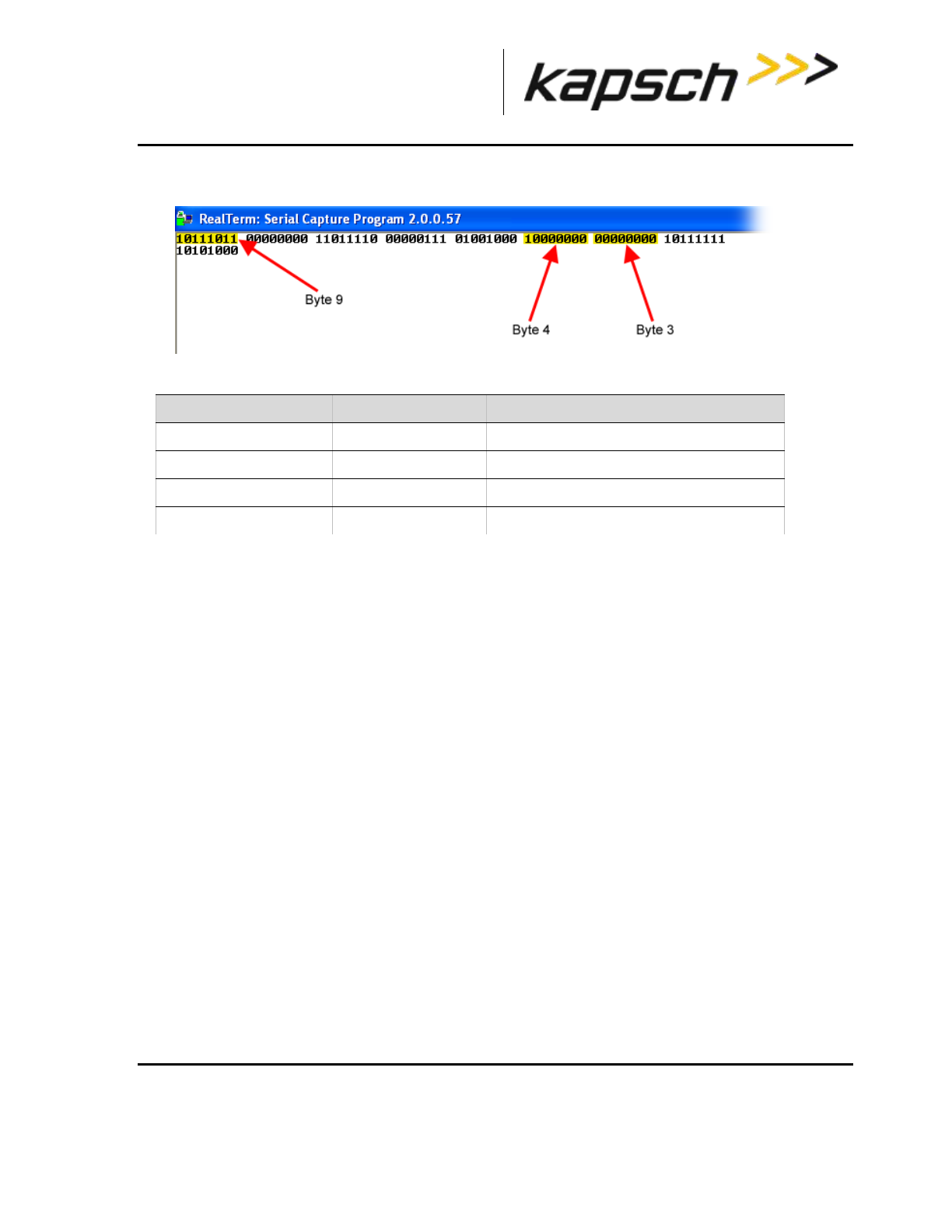
_
JANUS® Multi-Protocol Reader Ver. 2: Maintenance Instructions
Confidential UM 360463-202: A12 (Draft) Page 205 of 291
© Kapsch TrafficCom Canada Inc. 2013
These drawings and specifications contain confidential and proprietary information and are the property of Kapsch TrafficCom Canada Inc. and are issued in strict
confidence and will be kept confidential and used solely for the purpose intended and for no other purpose and shall not be transmitted, reproduced, copied, and/or
used as the basis for manufacture or sale of apparatus unless otherwise agreed to in writing by Kapsch TrafficCom Canada Inc.
FILE: MPR2_OPERATIONS_AND_MAINTENANCE-MANUAL_REV A12.DOCX 05/08/2014 11:24
Kapsch TrafficCom
Figure 6-2: Typical MRFM Heartbeat message
Table 6-6: MRFM fault codes
Testing the CTM Ethernet 1 port
This test verifies that a CTM Ethernet 1 port is working properly.
Prerequisites: A service laptop.
1. Connect a service laptop directly to CTM Ethernet 1 port being tested (see Connecting a service laptop to
the Reader, page 40).
Ensure that you can access the CTM web interface with the service laptop (see Accessing the CTM
web interface, page 41). This confirms the Ethernet port is functional.
Testing an LPM COM port
This test verifies that an LPM port is working properly and requires a simple loop-back connector.
Prerequisites: Connect the service laptop to the Reader configuration port to access the CTM web
interface. Refer to Connecting a service laptop to the Reader, page 40. You must have Advanced User
permissions.
Note: All OBU transactions on this port are buffered while the LC is disconnected from the LPM ports to
perform the test.
1. Disconnect the serial cable from the LPM COM port being tested.
Note: The LPM is either RS-232 or RS-422. The loop-back test will only work if the appropriate loop-back
connector is used.
Byte number
Value
Meaning
Byte 4
10000000
normal lane operation
Byte 4
10000001
lane hardware fault
Byte 3
00000000
normal lane operation
Byte 3
00000001
no activity on backplane control lines
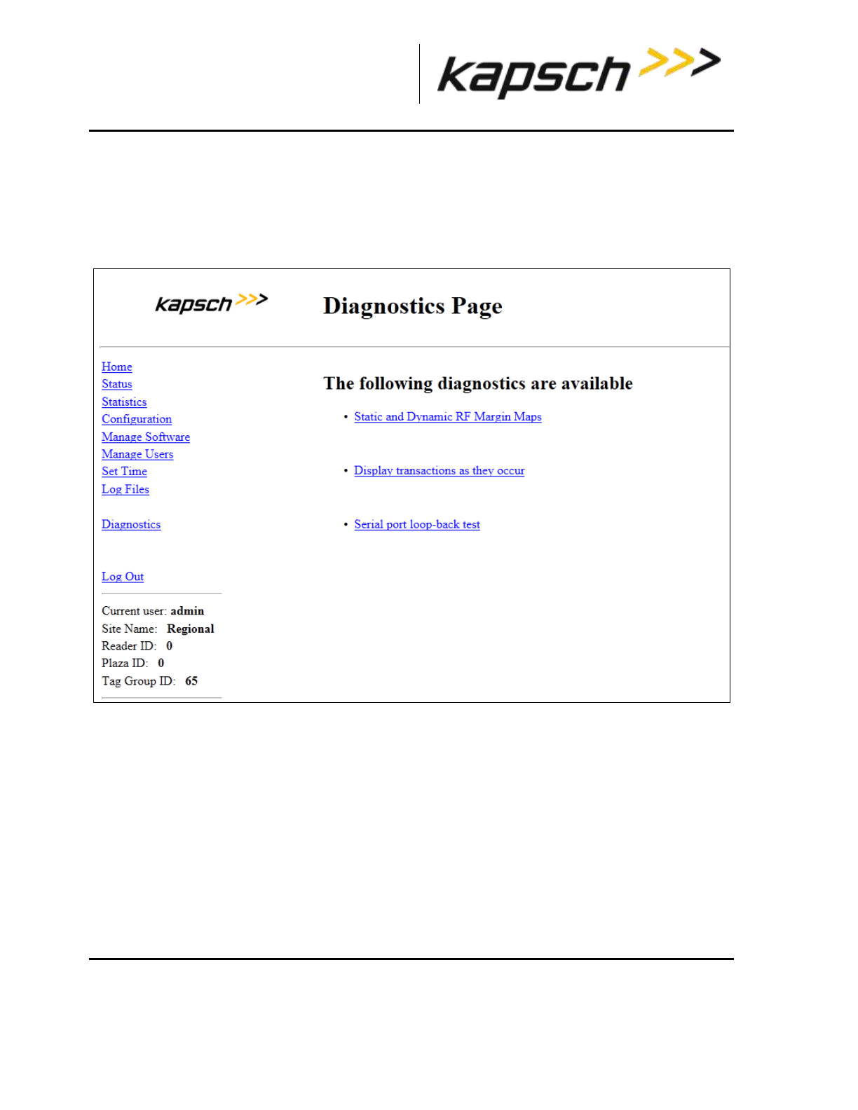
_
JANUS® Multi-Protocol Reader Ver. 2: Maintenance Instructions
Confidential UM 360463-202: A12 (Draft) Page 206 of 291
© Kapsch TrafficCom Canada Inc. 2013
These drawings and specifications contain confidential and proprietary information and are the property of Kapsch TrafficCom Canada Inc. and are issued in strict
confidence and will be kept confidential and used solely for the purpose intended and for no other purpose and shall not be transmitted, reproduced, copied, and/or
used as the basis for manufacture or sale of apparatus unless otherwise agreed to in writing by Kapsch TrafficCom Canada Inc.
FILE: MPR2_OPERATIONS_AND_MAINTENANCE-MANUAL_REV A12.DOCX 05/08/2014 11:24
Kapsch TrafficCom
2. Connect the appropriate loop-back connector to the COM port. In the RS-232 loop-back connector, the Tx
and Rx signals are connected. In the RS-422 loop-back connector, the Tx+ and Rx+ signals are
connected and the Tx- and Rx- signals are connected. The LPM RS-232 pin outs are shown on page
268; the LPM RS-422 pin outs are shown on page 269.
3. Select the Diagnostics link on the left side panel of the CTM web interface.
Result: The following screen appears.
4. Select the Serial port loop-back test link.
Result: The following screen appears.
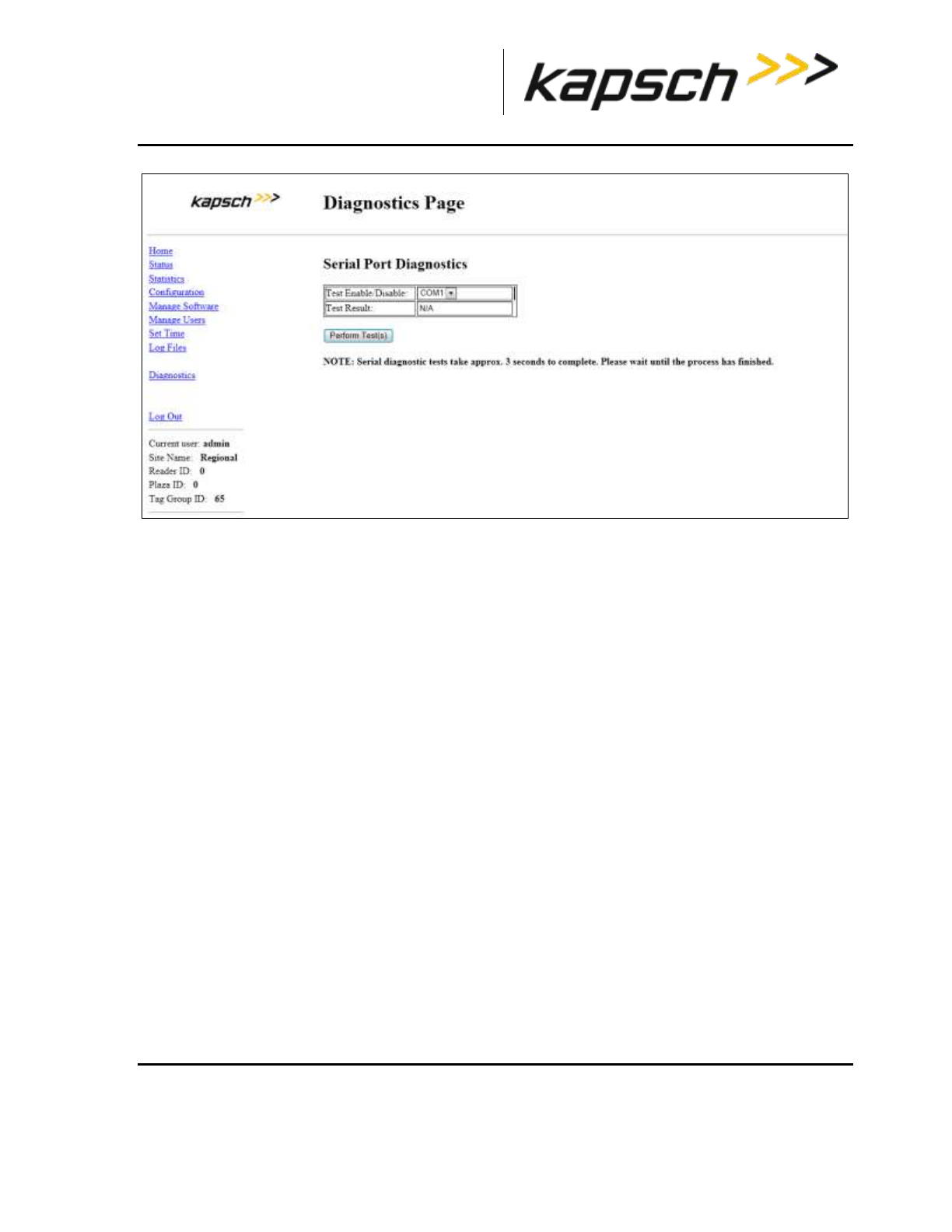
_
JANUS® Multi-Protocol Reader Ver. 2: Maintenance Instructions
Confidential UM 360463-202: A12 (Draft) Page 207 of 291
© Kapsch TrafficCom Canada Inc. 2013
These drawings and specifications contain confidential and proprietary information and are the property of Kapsch TrafficCom Canada Inc. and are issued in strict
confidence and will be kept confidential and used solely for the purpose intended and for no other purpose and shall not be transmitted, reproduced, copied, and/or
used as the basis for manufacture or sale of apparatus unless otherwise agreed to in writing by Kapsch TrafficCom Canada Inc.
FILE: MPR2_OPERATIONS_AND_MAINTENANCE-MANUAL_REV A12.DOCX 05/08/2014 11:24
Kapsch TrafficCom
5. Select the LPM COM port from the Test Enable/Disable drop-down box.
6. Click the Perform Test(s) button.
Result: The test result displays.
7. If the test passes, the LPM COM port is functional.
8. If the test fails, ensure the correct loop-back connector was used, then, replace the CTM and repeat steps
4 and 6.
9. If the test fails again, replace the LPM.
Testing the Synchronization Circuit
This first part of this test checks the functionality of one Reader’s SPM. The second part of this test
checks the Synchronization wiring from one Reader’s SPM to the synchronization circuit terminal block
Prerequisites:
At least one RF module installed in the Reader
Both Primary and Secondary CTMs are configured the same
Synchronization enabled
Testing the SPM and CTM
1. Disconnect the Synchronization circuit wiring from the SPM terminal block
2. Using two short jumper wires connect Tx+ to Rx+ and Tx- to Rx- on the SPM terminal block, leaving the GND
terminals unconnected (see SPM terminal block connections, page 267).
3. If the SYNC LED on both CTM’s illuminates solid green, the SPM and CTM’s are functioning properly.
4. Reconnect the synchronization circuit to the SPM terminal block.
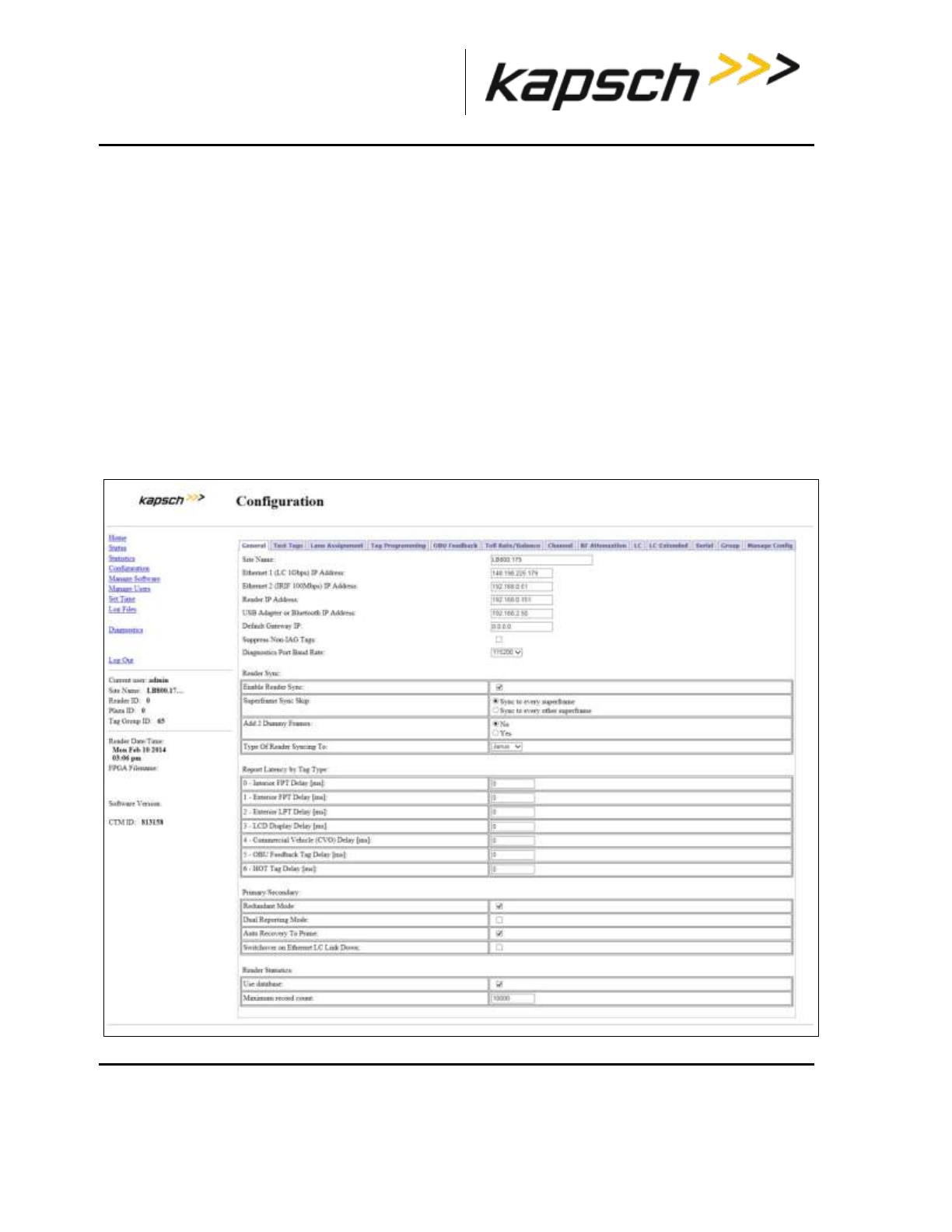
_
JANUS® Multi-Protocol Reader Ver. 2: Maintenance Instructions
Confidential UM 360463-202: A12 (Draft) Page 208 of 291
© Kapsch TrafficCom Canada Inc. 2013
These drawings and specifications contain confidential and proprietary information and are the property of Kapsch TrafficCom Canada Inc. and are issued in strict
confidence and will be kept confidential and used solely for the purpose intended and for no other purpose and shall not be transmitted, reproduced, copied, and/or
used as the basis for manufacture or sale of apparatus unless otherwise agreed to in writing by Kapsch TrafficCom Canada Inc.
FILE: MPR2_OPERATIONS_AND_MAINTENANCE-MANUAL_REV A12.DOCX 05/08/2014 11:24
Kapsch TrafficCom
Testing the Synchronization hub cabling
1. If the SYNC LED on the CTM does not illuminate solid green with a functional SPM and CTM connected to the
Synchronization circuit, the problem is with the wiring between the SPM and the synchronization hub terminal
block.
Testing the MRFM-S slots
The following test is to verify that all MRFM-S slots in the upper portion of the Reader rack are
functional.
Prerequisites: Connect the service laptop to to access the CTM web interface. Refer to Connecting a
service laptop to the Reader, page 40. One functional MRFM-S is installed in the RF slot 1 of the
Reader rack.
1. Select the Configuration link on the left side panel.
Result: The following screen appears.
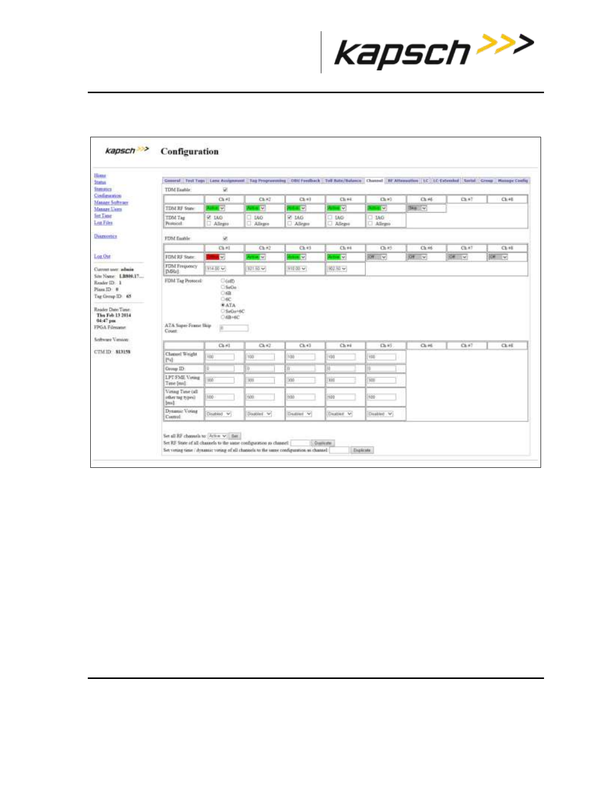
_
JANUS® Multi-Protocol Reader Ver. 2: Maintenance Instructions
Confidential UM 360463-202: A12 (Draft) Page 209 of 291
© Kapsch TrafficCom Canada Inc. 2013
These drawings and specifications contain confidential and proprietary information and are the property of Kapsch TrafficCom Canada Inc. and are issued in strict
confidence and will be kept confidential and used solely for the purpose intended and for no other purpose and shall not be transmitted, reproduced, copied, and/or
used as the basis for manufacture or sale of apparatus unless otherwise agreed to in writing by Kapsch TrafficCom Canada Inc.
FILE: MPR2_OPERATIONS_AND_MAINTENANCE-MANUAL_REV A12.DOCX 05/08/2014 11:24
Kapsch TrafficCom
2. Click the Channel tab.
Result: The following screen appears.
2. Set Ch# (where the RF module is installed) to active and press Enter.
3. Ensure that the DATA LED on the RF module illuminates solid green.
4. From the Channel tab on the Configuration page, select Offline from the RF State drop-down box.
5. Press Enter.
6. Ensure that the DATA LED on the RF module is off.
7. Move the RF module to the next slot and repeat steps 1 and 6.
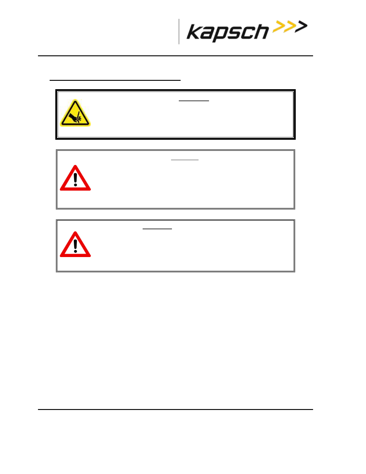
_
JANUS® Multi-Protocol Reader Ver. 2: Maintenance Instructions
Confidential UM 360463-202: A12 (Draft) Page 210 of 291
© Kapsch TrafficCom Canada Inc. 2013
These drawings and specifications contain confidential and proprietary information and are the property of Kapsch TrafficCom Canada Inc. and are issued in strict
confidence and will be kept confidential and used solely for the purpose intended and for no other purpose and shall not be transmitted, reproduced, copied, and/or
used as the basis for manufacture or sale of apparatus unless otherwise agreed to in writing by Kapsch TrafficCom Canada Inc.
FILE: MPR2_OPERATIONS_AND_MAINTENANCE-MANUAL_REV A12.DOCX 05/08/2014 11:24
Kapsch TrafficCom
7. MAINTENANCE PROCEDURES
WARNING:
THE MODULES MAY HAVE SHARP EDGES. HANDLE THE MODULES
CAREFULLY. WHENEVER POSSIBLE, USE A MODULE EXTRACTION TOOL
TO REMOVE A MODULE.
CAUTION:
Improper modification of configuration parameters may adversely
affect system operation. The default values may not be appropriate for
the specific application. It is the system integrator’s responsibility to
tailor the configuration parameters to the specific operating
environment.
CAUTION: Redundant Reader
Both CTMs in a redundant Reader must be properly configured. Each
CTM has its own browser interface and is configured independently.
Ensure any configuration changes made to one CTM are applied to the
other CTM, as required.
Corrective maintenance procedures
Note: When removing or installing ESD sensitive equipment always follow the accepted practices for ESD
protection.
The inspect, clean and system re-test methodology is used for all system maintenance. This type of
maintenance consists of the following general steps.
1. Inspect all Reader sub-system components and connections.
Inspect the PSM fuses; they should not appear darkened or burned.
Make sure that all plug-in components are properly seated in their mating connectors.
Determine if the components and/or connections require cleaning. To clean component assemblies,
use a portable vacuum cleaning tool with a non-conductive tip/brush. To clean component connector
contacts, use a contact cleaner spray that does not contain a trichloroethylene based solvent or a
Freon® based propellant.
Attention: Pre-authorized lane closure is required if the MRFM-S modules need to be cleaned.

_
JANUS® Multi-Protocol Reader Ver. 2: Maintenance Instructions
Confidential UM 360463-202: A12 (Draft) Page 211 of 291
© Kapsch TrafficCom Canada Inc. 2013
These drawings and specifications contain confidential and proprietary information and are the property of Kapsch TrafficCom Canada Inc. and are issued in strict
confidence and will be kept confidential and used solely for the purpose intended and for no other purpose and shall not be transmitted, reproduced, copied, and/or
used as the basis for manufacture or sale of apparatus unless otherwise agreed to in writing by Kapsch TrafficCom Canada Inc.
FILE: MPR2_OPERATIONS_AND_MAINTENANCE-MANUAL_REV A12.DOCX 05/08/2014 11:24
Kapsch TrafficCom
If cleaning is required:
2. Activate the side of the Reader not being cleaned (see Manually switching a Reader to the redundant
side page 40).
3. Power down the side of the Reader to be cleaned.
4. Clean the components and connections and then Power up and activate this Reader side.
5. Power down the remaining Reader side.
6. Clean the components and connections then Power up and activate, if necessary, this Reader side.
7. Test all system functions (see Troubleshooting and Testing, page 190).
Preventive maintenance procedures and scheduling
Attention: Only Kapsch Service-trained service maintenance personnel are to perform
these tasks.
Once a year:
1. Perform RF measurements to verify the cables and MRFM-S. It is recommended a commercial off-the
shelf instrument is used which supports Cable Analyzer Testing, to show faults inside cables, and Voltage
Network Analysis, to verify connection integrity and end to end connectivity and gain.
2. Verify module output power and power at antenna using a commercial off-the shelf spectrum analyzer.
With power off:
1. Inspect and clean the Reader cabinet as needed, depending on the site environmental conditions, such
as contamination by dust. As a minimum, inspect and clean the cabinet interior and components once per
year.
2. Inspect the antenna waterproofing and ensure that any seal is secure.
3. Inspect the antenna weep hole. Remove any dust, dirt or other obstructions.
4. Check ground connectivity for exterior ground connection to reader system ground
Attention: Pre-authorized lane closure is required before continuing with this procedure.
Note: For each channel, go into the web interface and disable the channel to be tested.
1. Disconnect and inspect in-line lightning suppressor.
2. Disconnect and inspect the exterior RF feedline cable and connectors exposed to the elements.
3. If corrosion is visible, replace the corroded connector and, if necessary, cut out the entire corroded
portion of the feedline cable. The antenna may require replacement if the mating female connector is
corroded.
4. When reconnecting connectors after inspection is complete, discard and replace self-amalgamating tape.
Every 4.5 years:
Note: The CMOS battery is not field-replaceable.
1. Replace the CTM CMOS battery.
Note: If a Kapsch TrafficCom maintenance agreement is in place, the CTM needing a new battery can
_
JANUS® Multi-Protocol Reader Ver. 2: Maintenance Instructions
Confidential UM 360463-202: A12 (Draft) Page 212 of 291
© Kapsch TrafficCom Canada Inc. 2013
These drawings and specifications contain confidential and proprietary information and are the property of Kapsch TrafficCom Canada Inc. and are issued in strict
confidence and will be kept confidential and used solely for the purpose intended and for no other purpose and shall not be transmitted, reproduced, copied, and/or
used as the basis for manufacture or sale of apparatus unless otherwise agreed to in writing by Kapsch TrafficCom Canada Inc.
FILE: MPR2_OPERATIONS_AND_MAINTENANCE-MANUAL_REV A12.DOCX 05/08/2014 11:24
Kapsch TrafficCom
be replaced by a spare CTM. The CTM is then sent to Kapsch Service to have its battery replaced.
MRFM-S replacement
The Reader does not need to be shut down to replace an MRFM-S.
Prerequisites: Connect the service laptop to the Reader configuration port to access the CTM web
interface. Refer to Connecting a service laptop to the Reader, page 40.
WARNING:
THE MODULES MAY HAVE SHARP EDGES. HANDLE THE MODULES
CAREFULLY. WHENEVER POSSIBLE, USE A MODULE EXTRACTION TOOL
TO REMOVE A MODULE.
WARNING:
THE MRFM-S MAY BECOME HOT UNDER NORMAL OPERATING
CONDITIONS. ENSURE THE MRFM-S HAS COOLED DOWN OR WEAR
GLOVES WHEN HANDLING THE MRFM-S.
Removing an MRFM-S
1. Select the Configuration link on the left side panel of the CTM web interface.
Result: The following screen appears.

_
JANUS® Multi-Protocol Reader Ver. 2: Maintenance Instructions
Confidential UM 360463-202: A12 (Draft) Page 213 of 291
© Kapsch TrafficCom Canada Inc. 2013
These drawings and specifications contain confidential and proprietary information and are the property of Kapsch TrafficCom Canada Inc. and are issued in strict
confidence and will be kept confidential and used solely for the purpose intended and for no other purpose and shall not be transmitted, reproduced, copied, and/or
used as the basis for manufacture or sale of apparatus unless otherwise agreed to in writing by Kapsch TrafficCom Canada Inc.
FILE: MPR2_OPERATIONS_AND_MAINTENANCE-MANUAL_REV A12.DOCX 05/08/2014 11:24
Kapsch TrafficCom
2. Click the Channel tab.
Result: The following screen appears.

_
JANUS® Multi-Protocol Reader Ver. 2: Maintenance Instructions
Confidential UM 360463-202: A12 (Draft) Page 214 of 291
© Kapsch TrafficCom Canada Inc. 2013
These drawings and specifications contain confidential and proprietary information and are the property of Kapsch TrafficCom Canada Inc. and are issued in strict
confidence and will be kept confidential and used solely for the purpose intended and for no other purpose and shall not be transmitted, reproduced, copied, and/or
used as the basis for manufacture or sale of apparatus unless otherwise agreed to in writing by Kapsch TrafficCom Canada Inc.
FILE: MPR2_OPERATIONS_AND_MAINTENANCE-MANUAL_REV A12.DOCX 05/08/2014 11:24
Kapsch TrafficCom
2. From the Channel tab on the Configuration page, set the RF State of the active MRFM-S to Offline.
3. Press Enter or select a different tab.
4. Disconnect the RF cable(s) from the MRFM-S appropriate port.
5. Loosen the screws securing the MRFM-S module to the Reader rack, and then remove the MRFM-S from
the Reader.
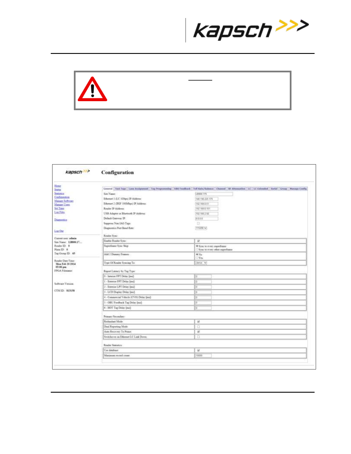
_
JANUS® Multi-Protocol Reader Ver. 2: Maintenance Instructions
Confidential UM 360463-202: A12 (Draft) Page 215 of 291
© Kapsch TrafficCom Canada Inc. 2013
These drawings and specifications contain confidential and proprietary information and are the property of Kapsch TrafficCom Canada Inc. and are issued in strict
confidence and will be kept confidential and used solely for the purpose intended and for no other purpose and shall not be transmitted, reproduced, copied, and/or
used as the basis for manufacture or sale of apparatus unless otherwise agreed to in writing by Kapsch TrafficCom Canada Inc.
FILE: MPR2_OPERATIONS_AND_MAINTENANCE-MANUAL_REV A12.DOCX 05/08/2014 11:24
Kapsch TrafficCom
Installing an MRFM-S
CAUTION:
To avoid damaging the modules, ensure that the connector on the
module is properly aligned with the connector on the DSM back plane
before the module is securely plugged into the DSM.
1. Insert the MRFM-S module into the Reader. Tighten the screws to secure the MRFM-S to the Reader
rack.
2. Connect the RF cable(s) to the MRFM-S appropriate port and tighten with a proper torque wrench.
3. Select the Configuration link on the left side panel of the CTM web interface.
Result: The following screen appears.
4. Click the Channel tab.
Result: The following screen appears.
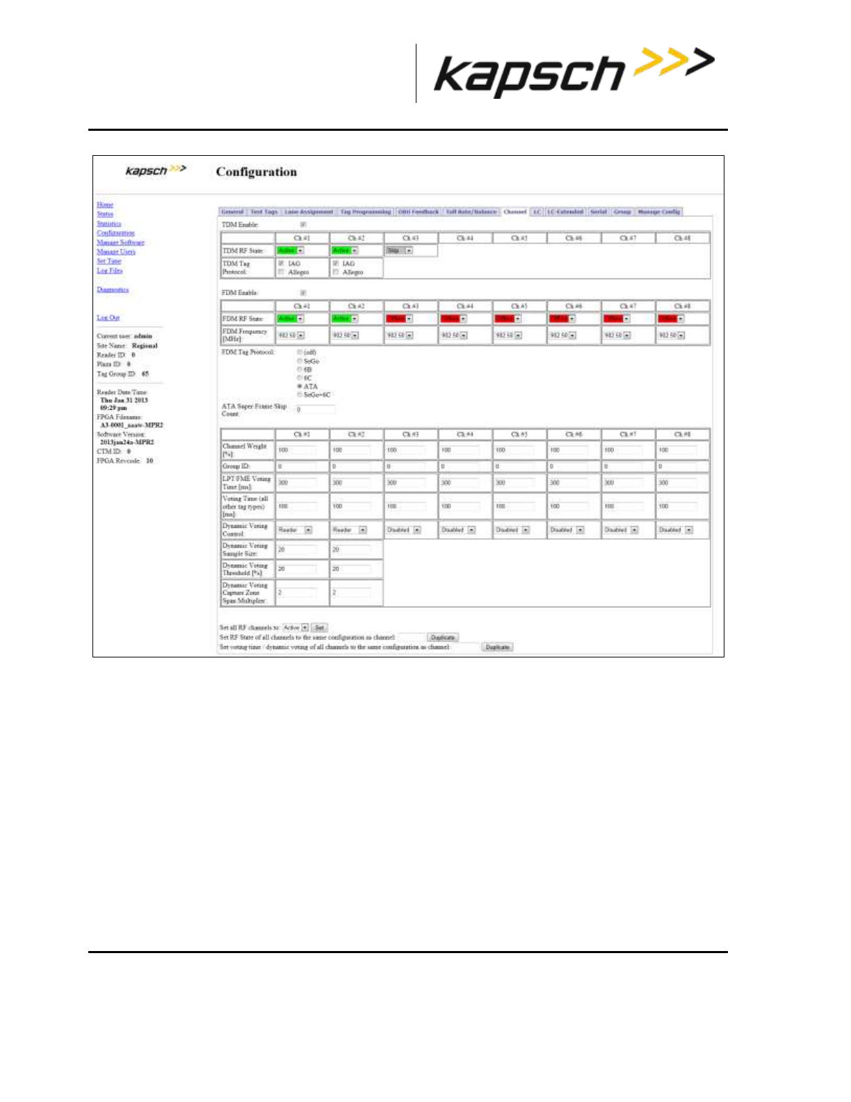
_
JANUS® Multi-Protocol Reader Ver. 2: Maintenance Instructions
Confidential UM 360463-202: A12 (Draft) Page 216 of 291
© Kapsch TrafficCom Canada Inc. 2013
These drawings and specifications contain confidential and proprietary information and are the property of Kapsch TrafficCom Canada Inc. and are issued in strict
confidence and will be kept confidential and used solely for the purpose intended and for no other purpose and shall not be transmitted, reproduced, copied, and/or
used as the basis for manufacture or sale of apparatus unless otherwise agreed to in writing by Kapsch TrafficCom Canada Inc.
FILE: MPR2_OPERATIONS_AND_MAINTENANCE-MANUAL_REV A12.DOCX 05/08/2014 11:24
Kapsch TrafficCom
5. Set the RF State of the Offline MRFM-S channels back to Active.
6. Press Enter or select a different tab.
7. Verify the DATA LED illuminates solid green.
Note: If the DATA LED does not illuminate solid green, see Troubleshooting tree: MRFM-S not working,
page 197.
8. Verify module output power and power at antenna using a commercial off-the shelf spectrum analyzer
9. Ensure the RF channel is capturing OBU data (see Troubleshooting tree: MRFM-S not working page
197).
Antenna replacement
Note: The Reader does not need shutting down to replace an antenna.
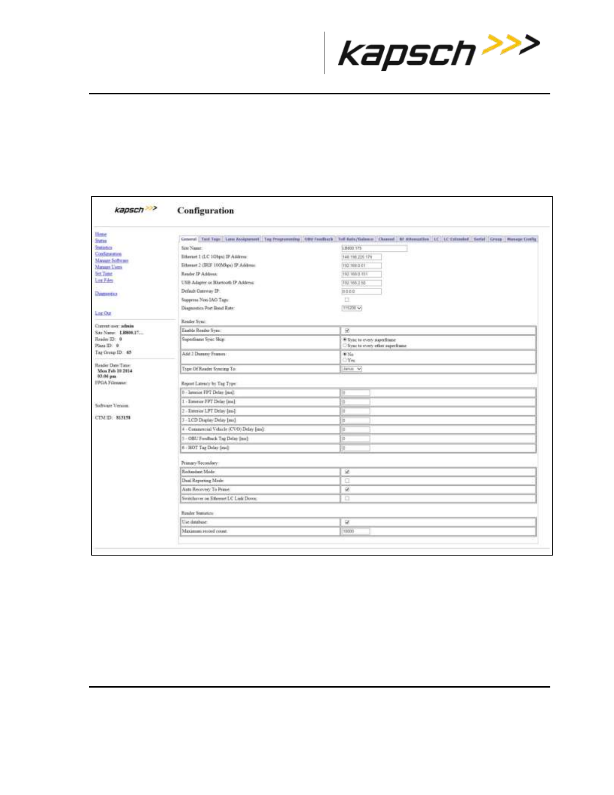
_
JANUS® Multi-Protocol Reader Ver. 2: Maintenance Instructions
Confidential UM 360463-202: A12 (Draft) Page 217 of 291
© Kapsch TrafficCom Canada Inc. 2013
These drawings and specifications contain confidential and proprietary information and are the property of Kapsch TrafficCom Canada Inc. and are issued in strict
confidence and will be kept confidential and used solely for the purpose intended and for no other purpose and shall not be transmitted, reproduced, copied, and/or
used as the basis for manufacture or sale of apparatus unless otherwise agreed to in writing by Kapsch TrafficCom Canada Inc.
FILE: MPR2_OPERATIONS_AND_MAINTENANCE-MANUAL_REV A12.DOCX 05/08/2014 11:24
Kapsch TrafficCom
Prerequisites: Connect the service laptop to the Reader configuration port to access the CTM web
interface. Refer to Connecting a service laptop to the Reader, page 40.
Removing an antenna
1. Select the Configuration link on the left side panel of the CTM web interface.
Result: The following screen appears.
2. Click the Channel tab.
Result: The following screen appears.

_
JANUS® Multi-Protocol Reader Ver. 2: Maintenance Instructions
Confidential UM 360463-202: A12 (Draft) Page 218 of 291
© Kapsch TrafficCom Canada Inc. 2013
These drawings and specifications contain confidential and proprietary information and are the property of Kapsch TrafficCom Canada Inc. and are issued in strict
confidence and will be kept confidential and used solely for the purpose intended and for no other purpose and shall not be transmitted, reproduced, copied, and/or
used as the basis for manufacture or sale of apparatus unless otherwise agreed to in writing by Kapsch TrafficCom Canada Inc.
FILE: MPR2_OPERATIONS_AND_MAINTENANCE-MANUAL_REV A12.DOCX 05/08/2014 11:24
Kapsch TrafficCom
3. Set the RF State of the MRFM-S connected to the antenna to Offline.
4. Press Enter or select a different tab.
5. Remove the antenna.
Installing an antenna
1. Install the antenna (see Installing an Antenna, page 149).
2. Select the Configuration link on the left side panel of the CTM web interface.
Result: The following screen appears.

_
JANUS® Multi-Protocol Reader Ver. 2: Maintenance Instructions
Confidential UM 360463-202: A12 (Draft) Page 219 of 291
© Kapsch TrafficCom Canada Inc. 2013
These drawings and specifications contain confidential and proprietary information and are the property of Kapsch TrafficCom Canada Inc. and are issued in strict
confidence and will be kept confidential and used solely for the purpose intended and for no other purpose and shall not be transmitted, reproduced, copied, and/or
used as the basis for manufacture or sale of apparatus unless otherwise agreed to in writing by Kapsch TrafficCom Canada Inc.
FILE: MPR2_OPERATIONS_AND_MAINTENANCE-MANUAL_REV A12.DOCX 05/08/2014 11:24
Kapsch TrafficCom
3. Click the Channel tab.
Result: The following screen appears.
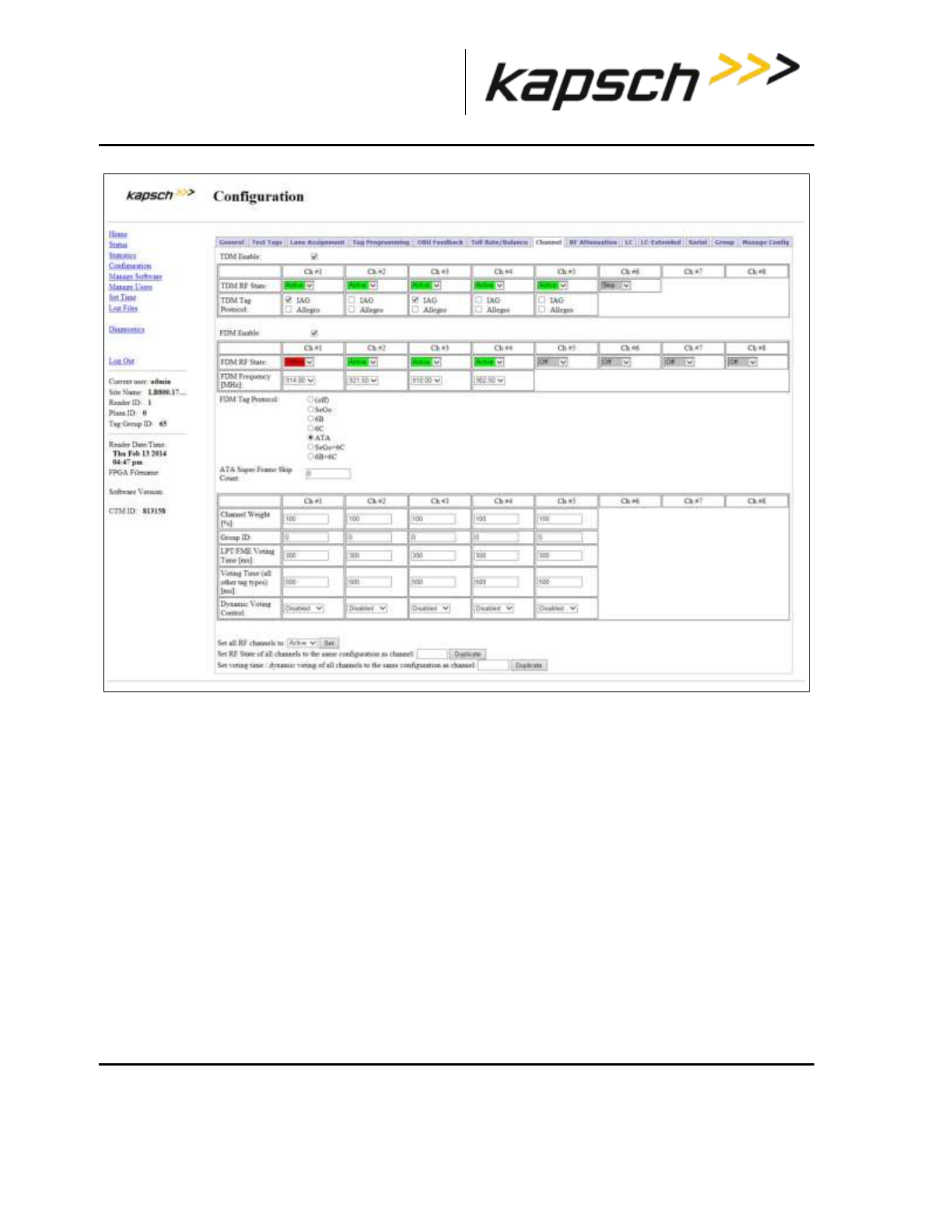
_
JANUS® Multi-Protocol Reader Ver. 2: Maintenance Instructions
Confidential UM 360463-202: A12 (Draft) Page 220 of 291
© Kapsch TrafficCom Canada Inc. 2013
These drawings and specifications contain confidential and proprietary information and are the property of Kapsch TrafficCom Canada Inc. and are issued in strict
confidence and will be kept confidential and used solely for the purpose intended and for no other purpose and shall not be transmitted, reproduced, copied, and/or
used as the basis for manufacture or sale of apparatus unless otherwise agreed to in writing by Kapsch TrafficCom Canada Inc.
FILE: MPR2_OPERATIONS_AND_MAINTENANCE-MANUAL_REV A12.DOCX 05/08/2014 11:24
Kapsch TrafficCom
4. Set the Offline MRFM-S RF State back to Active.
5. Press Enter.
6. Verify the DATA LED illuminates solid green.
7. Verify module output powers and power at antenna using a commercial off-the shelf spectrum analyzer .
8. Ensure the MRFM-S is capturing OBU data (see Monitoring OBU transactions as they occur via the
Diagnostics page, page 58).
RF cable or connector replacement
Note: The Reader does not need shutting down to replace an RF cable or connector.
Prerequisites: Connect the service laptop to the Reader configuration port to access the CTM web
interface.
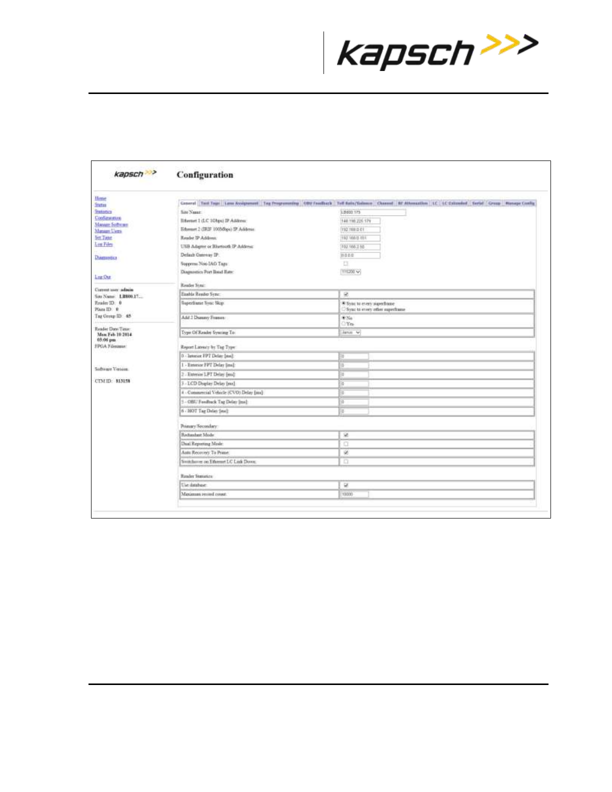
_
JANUS® Multi-Protocol Reader Ver. 2: Maintenance Instructions
Confidential UM 360463-202: A12 (Draft) Page 221 of 291
© Kapsch TrafficCom Canada Inc. 2013
These drawings and specifications contain confidential and proprietary information and are the property of Kapsch TrafficCom Canada Inc. and are issued in strict
confidence and will be kept confidential and used solely for the purpose intended and for no other purpose and shall not be transmitted, reproduced, copied, and/or
used as the basis for manufacture or sale of apparatus unless otherwise agreed to in writing by Kapsch TrafficCom Canada Inc.
FILE: MPR2_OPERATIONS_AND_MAINTENANCE-MANUAL_REV A12.DOCX 05/08/2014 11:24
Kapsch TrafficCom
Removing RF cable/connector
1. Select the Configuration link on the left side panel.
Result: The following screen appears.
2. Click the Channel tab.
Result: The following screen appears.

_
JANUS® Multi-Protocol Reader Ver. 2: Maintenance Instructions
Confidential UM 360463-202: A12 (Draft) Page 222 of 291
© Kapsch TrafficCom Canada Inc. 2013
These drawings and specifications contain confidential and proprietary information and are the property of Kapsch TrafficCom Canada Inc. and are issued in strict
confidence and will be kept confidential and used solely for the purpose intended and for no other purpose and shall not be transmitted, reproduced, copied, and/or
used as the basis for manufacture or sale of apparatus unless otherwise agreed to in writing by Kapsch TrafficCom Canada Inc.
FILE: MPR2_OPERATIONS_AND_MAINTENANCE-MANUAL_REV A12.DOCX 05/08/2014 11:24
Kapsch TrafficCom
3. Set the RF State of the MRFM-S whose cable or connector is being replaced to Offline.
4. Press Enter.
5. Remove the RF cables or connectors.
Installing an RF cable/connector
Prerequisites: Self-amalgamating tape for connections. Connect the service laptop to the Reader
configuration port to access the CTM web interface. Refer to Connecting a service laptop to the
Reader, page 40.
1. Install the RF cables or connectors.
2. Apply new self-amalgamating tape to the connections.
3. Select the Configuration link on the left side panel of the CTM web interface.
Result: The following screen appears.
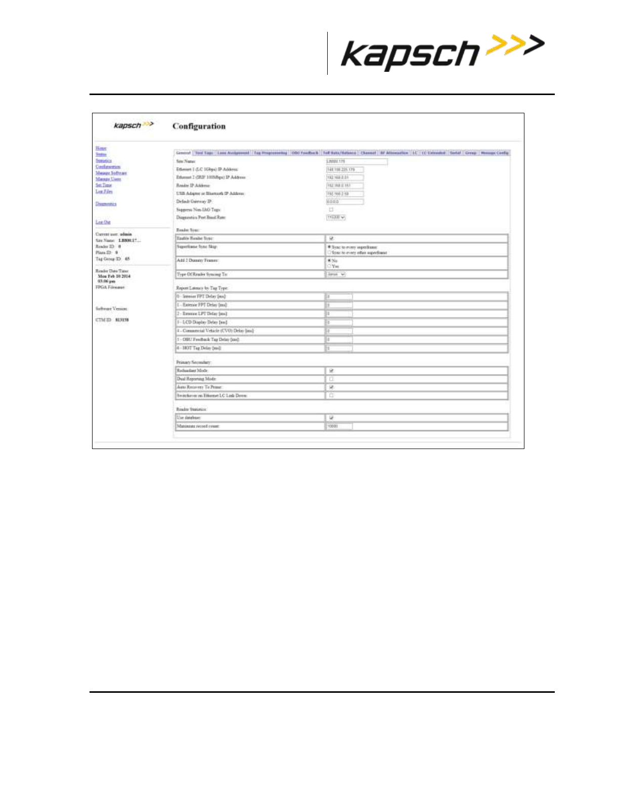
_
JANUS® Multi-Protocol Reader Ver. 2: Maintenance Instructions
Confidential UM 360463-202: A12 (Draft) Page 223 of 291
© Kapsch TrafficCom Canada Inc. 2013
These drawings and specifications contain confidential and proprietary information and are the property of Kapsch TrafficCom Canada Inc. and are issued in strict
confidence and will be kept confidential and used solely for the purpose intended and for no other purpose and shall not be transmitted, reproduced, copied, and/or
used as the basis for manufacture or sale of apparatus unless otherwise agreed to in writing by Kapsch TrafficCom Canada Inc.
FILE: MPR2_OPERATIONS_AND_MAINTENANCE-MANUAL_REV A12.DOCX 05/08/2014 11:24
Kapsch TrafficCom
4. Click the Channel tab.
Result: The following screen appears.
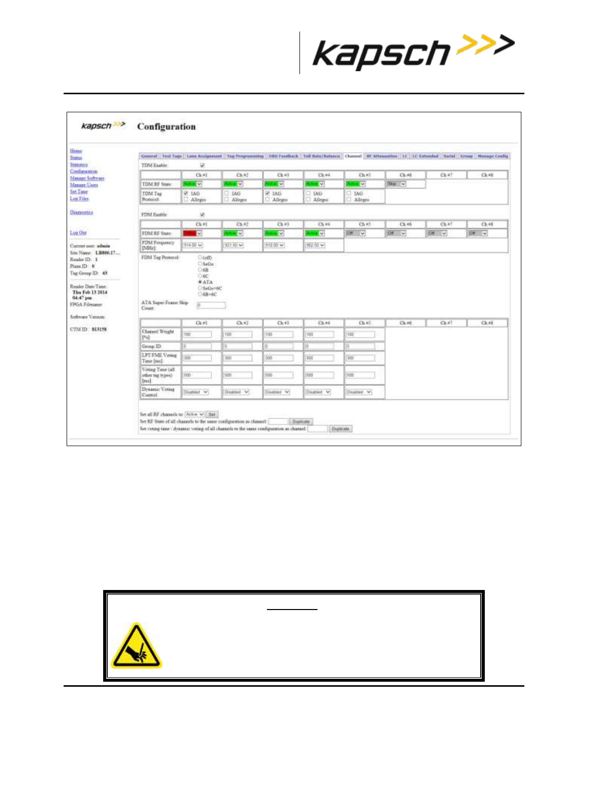
_
JANUS® Multi-Protocol Reader Ver. 2: Maintenance Instructions
Confidential UM 360463-202: A12 (Draft) Page 224 of 291
© Kapsch TrafficCom Canada Inc. 2013
These drawings and specifications contain confidential and proprietary information and are the property of Kapsch TrafficCom Canada Inc. and are issued in strict
confidence and will be kept confidential and used solely for the purpose intended and for no other purpose and shall not be transmitted, reproduced, copied, and/or
used as the basis for manufacture or sale of apparatus unless otherwise agreed to in writing by Kapsch TrafficCom Canada Inc.
FILE: MPR2_OPERATIONS_AND_MAINTENANCE-MANUAL_REV A12.DOCX 05/08/2014 11:24
Kapsch TrafficCom
5. Set the Offline MRFM-S RF State back to Active.
6. Press Enter.
7. Verify that the DATA LED illuminates solid green.
8. Verify module output powers and power at antenna using a commercial off-the shelf spectrum analyzer.
9. Ensure the MRFM-S is capturing OBU data (see Monitoring OBU transactions as they occur via the
Diagnostics page, page 58).
CTM replacement
WARNING:
THE MODULES MAY HAVE SHARP EDGES. HANDLE THE MODULES
CAREFULLY. WHENEVER POSSIBLE, USE A MODULE EXTRACTION
TOOL TO REMOVE A MODULE.
_
JANUS® Multi-Protocol Reader Ver. 2: Maintenance Instructions
Confidential UM 360463-202: A12 (Draft) Page 225 of 291
© Kapsch TrafficCom Canada Inc. 2013
These drawings and specifications contain confidential and proprietary information and are the property of Kapsch TrafficCom Canada Inc. and are issued in strict
confidence and will be kept confidential and used solely for the purpose intended and for no other purpose and shall not be transmitted, reproduced, copied, and/or
used as the basis for manufacture or sale of apparatus unless otherwise agreed to in writing by Kapsch TrafficCom Canada Inc.
FILE: MPR2_OPERATIONS_AND_MAINTENANCE-MANUAL_REV A12.DOCX 05/08/2014 11:24
Kapsch TrafficCom
CAUTION:
Removing a powered CTM from the Reader rack can damage the
CTM. Before removing a CTM from the Reader, ensure that power
on the affected side of the Reader is turned off, i.e. the power
switch on the PSM is in the off position, or the PSM AC input
power cord is disconnected.
Removing a CTM
1. Switch the Reader over to the side with the CTM that is not being replaced (see Manually switching a
Reader to the redundant side, page 40).
2. Set the PSM powering the CTM being replaced to the off position.
3. Label and then disconnect any communication cables connected to the CTM.
4. Remove the faulty CTM from the Reader rack.
Installing a CTM
CAUTION:
To avoid damaging the modules, ensure that the connector on the
module is properly aligned with the connector on the DSM back
plane before the module is securely plugged into the DSM.
1. Install a new CTM in the Reader Rack.
2. Reconnect the communication cables to the CTM.
3. Set the PSM and CTM to the on position.
4. Switch the Reader to the new CTM side (see Manually switching a Reader to the redundant side, page
40).
5. If the CTM is in an IR network, reboot the CTM (see Rebooting the CTM, page 230).
_
JANUS® Multi-Protocol Reader Ver. 2: Maintenance Instructions
Confidential UM 360463-202: A12 (Draft) Page 226 of 291
© Kapsch TrafficCom Canada Inc. 2013
These drawings and specifications contain confidential and proprietary information and are the property of Kapsch TrafficCom Canada Inc. and are issued in strict
confidence and will be kept confidential and used solely for the purpose intended and for no other purpose and shall not be transmitted, reproduced, copied, and/or
used as the basis for manufacture or sale of apparatus unless otherwise agreed to in writing by Kapsch TrafficCom Canada Inc.
FILE: MPR2_OPERATIONS_AND_MAINTENANCE-MANUAL_REV A12.DOCX 05/08/2014 11:24
Kapsch TrafficCom
SPM replacement
WARNING:
THE MODULES MAY HAVE SHARP EDGES. HANDLE THE MODULES
CAREFULLY. WHENEVER POSSIBLE, USE A MODULE EXTRACTION
TOOL TO REMOVE A MODULE.
Removing an SPM
1. Without disconnecting any of the sync wiring from the SPM terminal block, disconnect the SPM terminal
block from the SPM.
2. Remove the SPM from the Reader rack.
Installing an SPM
CAUTION:
To avoid damaging the modules, ensure that the connector on the
module is properly aligned with the connector on the DSM back
plane before the module is securely plugged into the DSM.
1. Install a new SPM in the Reader Rack.
2. Reconnect the SPM terminal block.
3. Test the SPM (see Testing the Synchronization Circuit, page 207).
LPM replacement
WARNING:
THE MODULES MAY HAVE SHARP EDGES. HANDLE THE MODULES
CAREFULLY. WHENEVER POSSIBLE, USE A MODULE EXTRACTION
TOOL TO REMOVE A MODULE.
Removing an LPM
1. Switch the Reader over to the side with the LPM that is not being replaced (see Manually switching a
Reader to the redundant side, page 40).
2. Remove the faulty LPM from the Reader rack.
_
JANUS® Multi-Protocol Reader Ver. 2: Maintenance Instructions
Confidential UM 360463-202: A12 (Draft) Page 227 of 291
© Kapsch TrafficCom Canada Inc. 2013
These drawings and specifications contain confidential and proprietary information and are the property of Kapsch TrafficCom Canada Inc. and are issued in strict
confidence and will be kept confidential and used solely for the purpose intended and for no other purpose and shall not be transmitted, reproduced, copied, and/or
used as the basis for manufacture or sale of apparatus unless otherwise agreed to in writing by Kapsch TrafficCom Canada Inc.
FILE: MPR2_OPERATIONS_AND_MAINTENANCE-MANUAL_REV A12.DOCX 05/08/2014 11:24
Kapsch TrafficCom
Installing an LPM
1. Install a new LPM in the Reader rack.
2. Switch the Reader back over to the new LPM side (see Manually switching a Reader to the redundant
side, page 40).
3. Test all the LPM COM ports (see Testing an LPM COM port, page 207).
PSM replacement
WARNING:
THE MODULES MAY HAVE SHARP EDGES. HANDLE THE MODULES
CAREFULLY. WHENEVER POSSIBLE, USE A MODULE EXTRACTION
TOOL TO REMOVE A MODULE.
WARNING:
THE PSM MAY BECOME HOT UNDER NORMAL OPERATING
CONDITIONS. ENSURE THE PSM HAS COOLED DOWN OR WEAR
GLOVES WHEN HANDLING THE PSM.
WARNING:
EXPOSED HIGH VOLTAGE IS PRESENT IN THE PSM. ENSURE THAT
THE POWER SWITCH IS SET TO THE OFF POSITION AND THAT THE
AC INPUT POWER CORD IS DISCONNECTED BEFORE REMOVING
THE PSM.
Removing a PSM
1. Switch the Reader over to the side with the PSM that is not being replaced (see Manually switching a
Reader to the redundant side, page 40).
2. Set the PSM power switch to the off position.
3. Remove the faulty PSM from the Reader rack.
_
JANUS® Multi-Protocol Reader Ver. 2: Maintenance Instructions
Confidential UM 360463-202: A12 (Draft) Page 228 of 291
© Kapsch TrafficCom Canada Inc. 2013
These drawings and specifications contain confidential and proprietary information and are the property of Kapsch TrafficCom Canada Inc. and are issued in strict
confidence and will be kept confidential and used solely for the purpose intended and for no other purpose and shall not be transmitted, reproduced, copied, and/or
used as the basis for manufacture or sale of apparatus unless otherwise agreed to in writing by Kapsch TrafficCom Canada Inc.
FILE: MPR2_OPERATIONS_AND_MAINTENANCE-MANUAL_REV A12.DOCX 05/08/2014 11:24
Kapsch TrafficCom
Installing a PSM
CAUTION:
To avoid damaging the modules, ensure that the connector on the
module properly aligns with the connector on the DSM back plane
before the module is securely plugged into the DSM.
1. Install a new PSM in the Reader Rack.
2. Set the power switch of the new PSM to the on position.
3. Ensure that the new PSM +5 and +15 LEDs illuminate solid green.
4. Switch the Reader back over to the new PSM side (see Manually switching a Reader to the redundant
side, page 39).
CFM replacement
WARNING:
THE MODULES MAY HAVE SHARP EDGES. HANDLE THE MODULES
CAREFULLY. WHENEVER POSSIBLE, USE A MODULE EXTRACTION
TOOL TO REMOVE A MODULE.
Removing a CFM
1. If possible, save the configuration file of the CFM being replaced (see Saving the Reader configuration,
page 243).
2. Remove the CTM on the side of the faulty CFM (see CTM, page 224).
3. While pushing on plastic clips, pull CFM straight out from DSM.
Installing a CFM
1. Push CFM straight into connector on DSM until an audible click is heard.
2. Install the CTM removed in step 2 (see CTM, page 224).
3. Load the configuration file saved in step 1 to the new CFM (see Uploading a saved configuration, page
246), or locate and upload the latest saved Reader configuration.
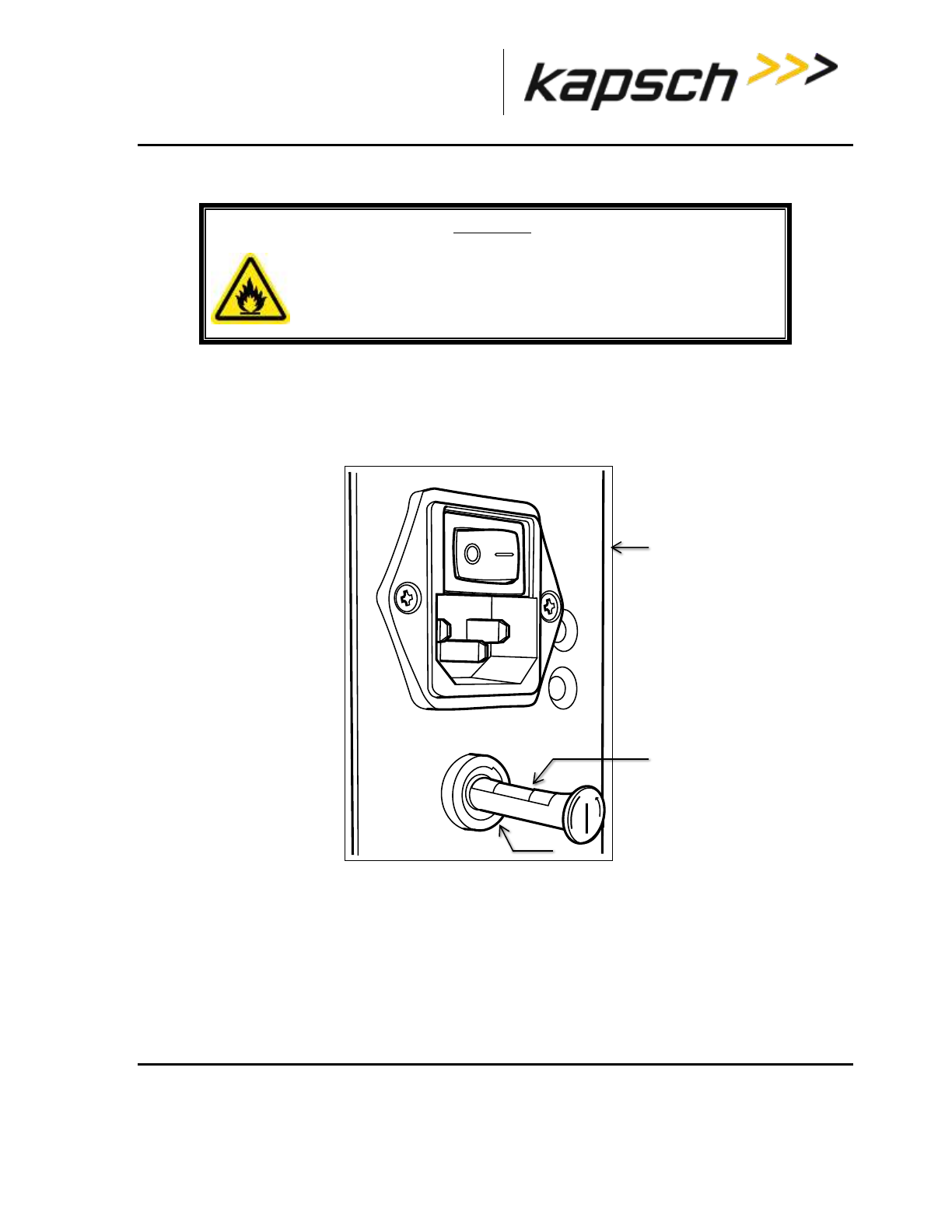
_
JANUS® Multi-Protocol Reader Ver. 2: Maintenance Instructions
Confidential UM 360463-202: A12 (Draft) Page 229 of 291
© Kapsch TrafficCom Canada Inc. 2013
These drawings and specifications contain confidential and proprietary information and are the property of Kapsch TrafficCom Canada Inc. and are issued in strict
confidence and will be kept confidential and used solely for the purpose intended and for no other purpose and shall not be transmitted, reproduced, copied, and/or
used as the basis for manufacture or sale of apparatus unless otherwise agreed to in writing by Kapsch TrafficCom Canada Inc.
FILE: MPR2_OPERATIONS_AND_MAINTENANCE-MANUAL_REV A12.DOCX 05/08/2014 11:24
Kapsch TrafficCom
Replacing a PSM fuse
WARNING:
INSTALLING A FUSE OF THE WRONG TYPE OR RATING MAY CAUSE
A FIRE. INSTALL A TIME LAG FUSE RATED FOR 10A.
1. Set the PSM power switch to the off position.
2. Disconnect the AC power cord.
3. Using a flat-tipped screwdriver, rotate the fuse holder counter-clockwise 180 degrees. Slide out the fuse
holder as shown in Figure 7-1.
Figure 7-1: PSM fuse and fuse holder
4. Rotate the fuse holder clockwise to allow the old fuse to fall free of the fuse holder.
5. Place the new fuse in the fuse holder then slide the fuse holder into the PSM.
6. Using a flat-tipped screwdriver, rotate the fuse holder 180 degrees to secure the fuse holder in the PSM.
PSM
fuse holder
fuse
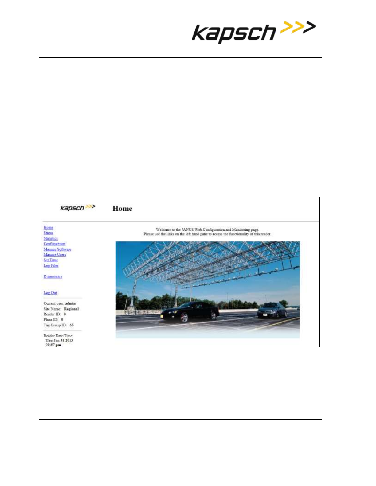
_
JANUS® Multi-Protocol Reader Ver. 2: Maintenance Instructions
Confidential UM 360463-202: A12 (Draft) Page 230 of 291
© Kapsch TrafficCom Canada Inc. 2013
These drawings and specifications contain confidential and proprietary information and are the property of Kapsch TrafficCom Canada Inc. and are issued in strict
confidence and will be kept confidential and used solely for the purpose intended and for no other purpose and shall not be transmitted, reproduced, copied, and/or
used as the basis for manufacture or sale of apparatus unless otherwise agreed to in writing by Kapsch TrafficCom Canada Inc.
FILE: MPR2_OPERATIONS_AND_MAINTENANCE-MANUAL_REV A12.DOCX 05/08/2014 11:24
Kapsch TrafficCom
Rebooting the CTM
This procedure outlines two ways of rebooting the CTM; using the ON/OFF switch on the CTM, and
using the Reboot button from the CTM web interface.
Prerequisites: To reboot from the browser interface, you must have Software Management
permissions.
Rebooting using CTM ON/OFF switch
1. Set the CTM ON/OFF switch to OFF.
2. After five seconds, set the CTM ON/OFF switch back to ON. The CTM POWER LEDs immediately
illuminate solid green. After 90 – 120 sec., the CTM STATUS LEDs illuminate their normal state (see LED
Status, page 192).
Rebooting from the browser interface
1. Login to the CTM web Interface.
Result: The following Main Page appears.
2. Select the Manage Software link on the left side panel of the CTM web interface.
Result: The following screen appears.
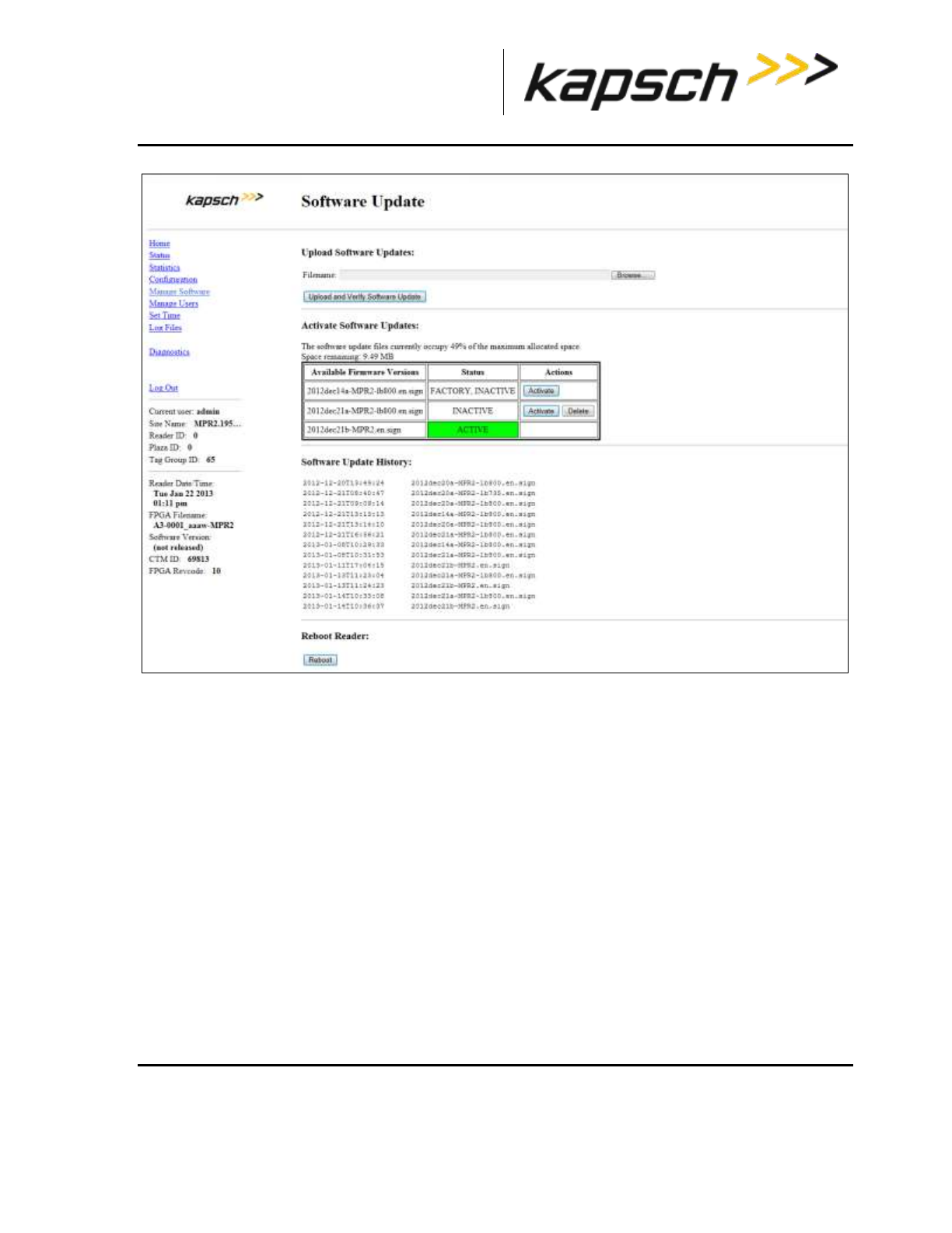
_
JANUS® Multi-Protocol Reader Ver. 2: Maintenance Instructions
Confidential UM 360463-202: A12 (Draft) Page 231 of 291
© Kapsch TrafficCom Canada Inc. 2013
These drawings and specifications contain confidential and proprietary information and are the property of Kapsch TrafficCom Canada Inc. and are issued in strict
confidence and will be kept confidential and used solely for the purpose intended and for no other purpose and shall not be transmitted, reproduced, copied, and/or
used as the basis for manufacture or sale of apparatus unless otherwise agreed to in writing by Kapsch TrafficCom Canada Inc.
FILE: MPR2_OPERATIONS_AND_MAINTENANCE-MANUAL_REV A12.DOCX 05/08/2014 11:24
Kapsch TrafficCom
3. Click the Reboot button
Configuring events that cause a switchover
Redundant Readers need to be configured in order to:
Determine whether the Reader switches over when there is a failure
Determine what failures cause a switchover
Determine if the Reader switches back to the primary side once a failure has cleared.
Prerequisites: The primary and secondary sides are both powered up. You must have Advanced
User permissions to configure redundancy settings in the browser interface.

_
JANUS® Multi-Protocol Reader Ver. 2: Maintenance Instructions
Confidential UM 360463-202: A12 (Draft) Page 232 of 291
© Kapsch TrafficCom Canada Inc. 2013
These drawings and specifications contain confidential and proprietary information and are the property of Kapsch TrafficCom Canada Inc. and are issued in strict
confidence and will be kept confidential and used solely for the purpose intended and for no other purpose and shall not be transmitted, reproduced, copied, and/or
used as the basis for manufacture or sale of apparatus unless otherwise agreed to in writing by Kapsch TrafficCom Canada Inc.
FILE: MPR2_OPERATIONS_AND_MAINTENANCE-MANUAL_REV A12.DOCX 05/08/2014 11:24
Kapsch TrafficCom
Manually select the active side and disable switchover
CAUTION:
If the primary or secondary side is forced active via the SPM redundancy
mode switch and that side fails, the Reader will not switch to the other
side and data could be lost.
1. Set the toggle switch on the SPM to the side to stay active, either SECONDARY or PRIMARY.
Result: This side is now active and no switchover will occur unlessa failure occurs.
Letting the Reader automatically choose the active side
1. Set the SPM toggle switch to AUTO.
Result: The primary side is now active by default, until a primary failure occurs.
Enabling the Reader to recover automatically to the primary side
1. Select the Auto Recovery to Prime check box then click the Update General Configuration button.
Result: The Reader will now automatically switch back to the primary side once a primary failure has
cleared.
Configuring the Reader to switch automatically over when an LC link is down
1. Select the Configuration link on the left side panel.
Result: The following screen appears.
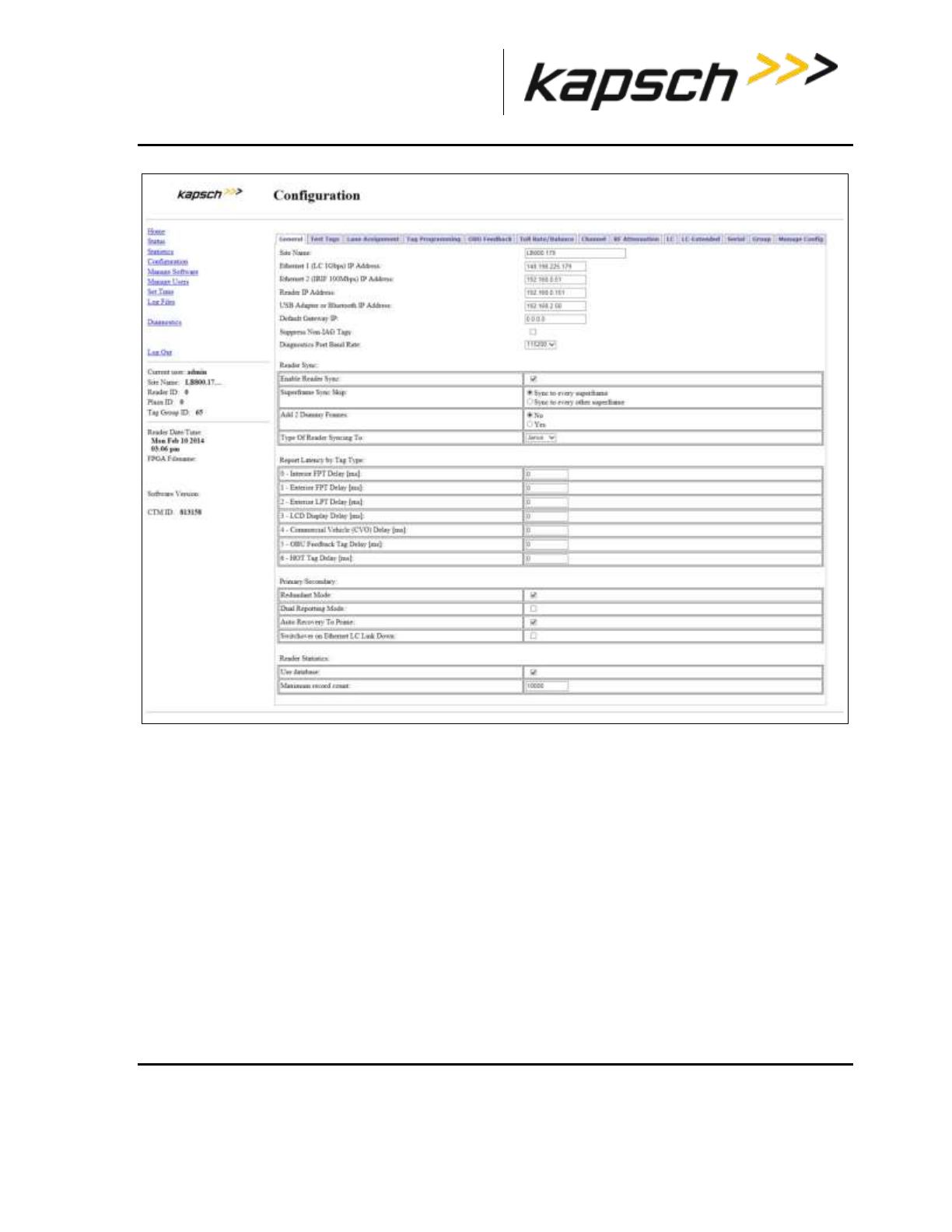
_
JANUS® Multi-Protocol Reader Ver. 2: Maintenance Instructions
Confidential UM 360463-202: A12 (Draft) Page 233 of 291
© Kapsch TrafficCom Canada Inc. 2013
These drawings and specifications contain confidential and proprietary information and are the property of Kapsch TrafficCom Canada Inc. and are issued in strict
confidence and will be kept confidential and used solely for the purpose intended and for no other purpose and shall not be transmitted, reproduced, copied, and/or
used as the basis for manufacture or sale of apparatus unless otherwise agreed to in writing by Kapsch TrafficCom Canada Inc.
FILE: MPR2_OPERATIONS_AND_MAINTENANCE-MANUAL_REV A12.DOCX 05/08/2014 11:24
Kapsch TrafficCom
2. Click the LC tab.
Result: The following screen appears.
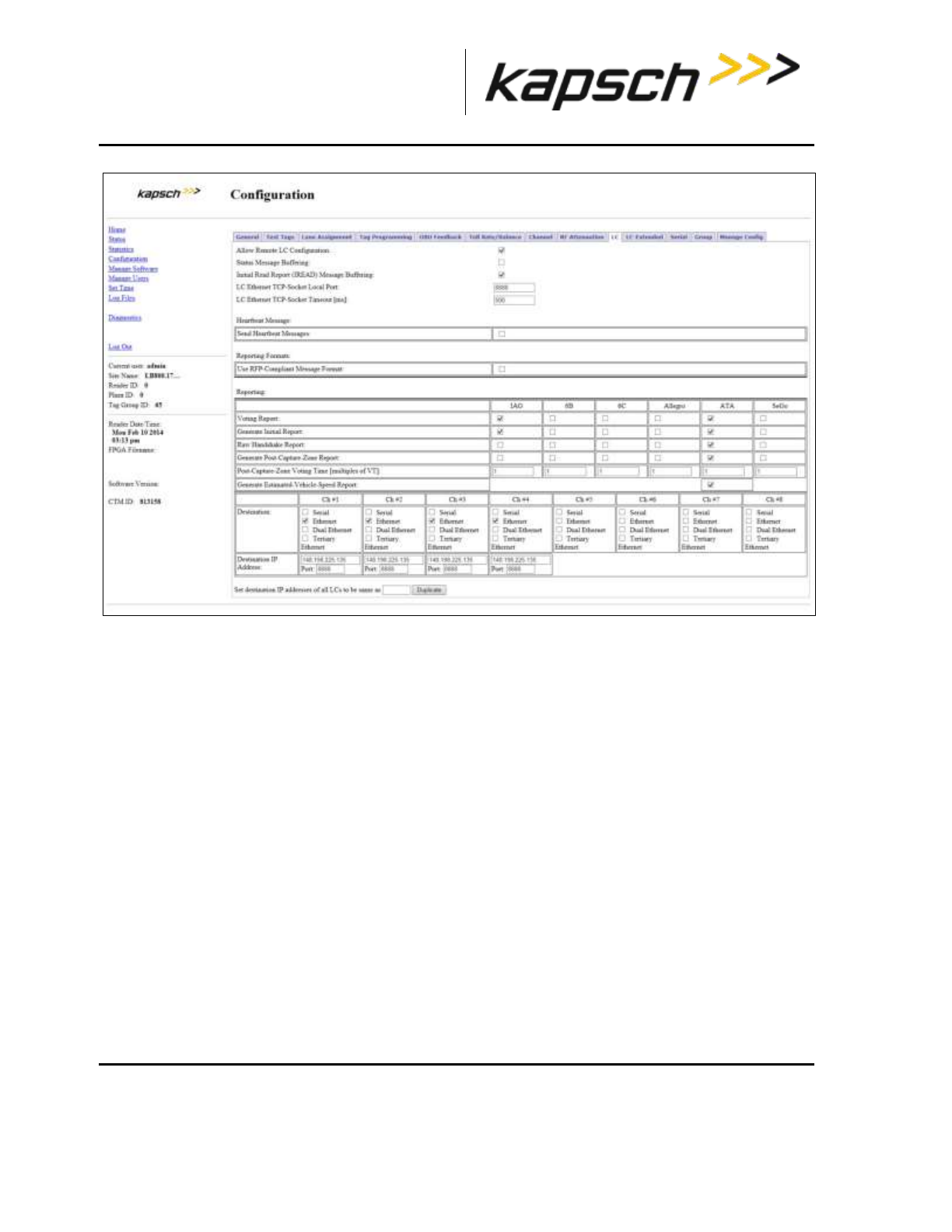
_
JANUS® Multi-Protocol Reader Ver. 2: Maintenance Instructions
Confidential UM 360463-202: A12 (Draft) Page 234 of 291
© Kapsch TrafficCom Canada Inc. 2013
These drawings and specifications contain confidential and proprietary information and are the property of Kapsch TrafficCom Canada Inc. and are issued in strict
confidence and will be kept confidential and used solely for the purpose intended and for no other purpose and shall not be transmitted, reproduced, copied, and/or
used as the basis for manufacture or sale of apparatus unless otherwise agreed to in writing by Kapsch TrafficCom Canada Inc.
FILE: MPR2_OPERATIONS_AND_MAINTENANCE-MANUAL_REV A12.DOCX 05/08/2014 11:24
Kapsch TrafficCom
3. Ensure that LC communications is configured, that is, the appropriate Ethernet and Serial selections are
made in the Destinations field.
4. Select the Send Heartbeat messages check box to enable sending heartbeat messaging, as required.
5. Enter a time, in seconds, in the Heartbeat Interval field. This number must be lower than the LC
communication error threshold.
6. Click the General tab.
Result: The following screen appears.

_
JANUS® Multi-Protocol Reader Ver. 2: Maintenance Instructions
Confidential UM 360463-202: A12 (Draft) Page 235 of 291
© Kapsch TrafficCom Canada Inc. 2013
These drawings and specifications contain confidential and proprietary information and are the property of Kapsch TrafficCom Canada Inc. and are issued in strict
confidence and will be kept confidential and used solely for the purpose intended and for no other purpose and shall not be transmitted, reproduced, copied, and/or
used as the basis for manufacture or sale of apparatus unless otherwise agreed to in writing by Kapsch TrafficCom Canada Inc.
FILE: MPR2_OPERATIONS_AND_MAINTENANCE-MANUAL_REV A12.DOCX 05/08/2014 11:24
Kapsch TrafficCom
7. Select the Switchover on Serial Link Down and/or Switchover on Ethernet LC Link Down check box, as
required.
8. Press Enter or select a different tab to accept the selections.
Note: When setting the LC Retry Timeout, consider the baud rate used to communicate with the LC and
the processing speed of the LC to avoid false failure reports.
9. If Switchover on Serial Link Down is enabled, from the Serial tab on the Configuration page, enter a
time, in milliseconds, in the LC Retry Timeout field. If an LC does not respond within this time, the
Reader will consider serial communications to the LC to be down and will trigger a switchover if the SPM
redundancy mode switch is in AUTO.
10. If Switchover on Ethernet LC Link Down is enabled, enter a time, in milliseconds, in the LC Ethernet
TCP-Socket Timeout text box. If an LC does not respond within this time, the Reader will consider
Ethernet communications to the LC to be down and could trigger a switchover if the SPM redundancy
mode switch is in AUTO.
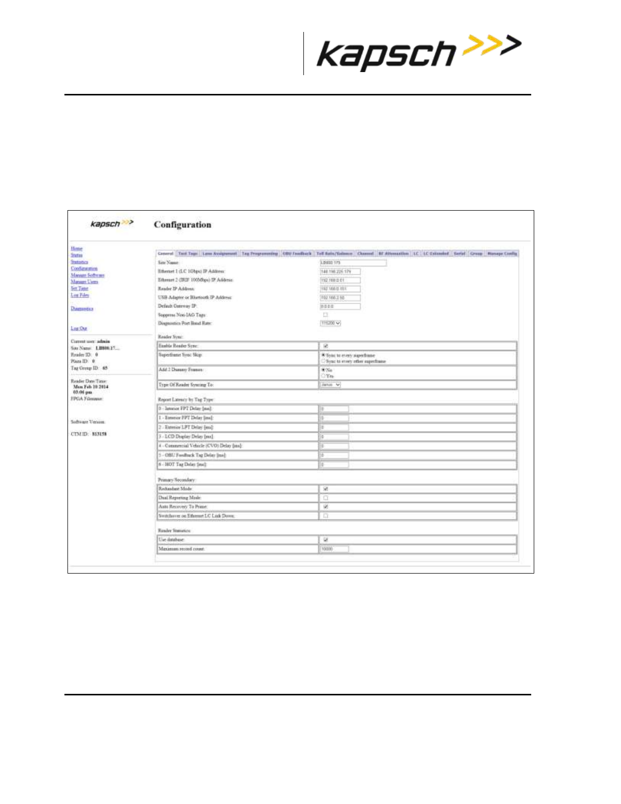
_
JANUS® Multi-Protocol Reader Ver. 2: Maintenance Instructions
Confidential UM 360463-202: A12 (Draft) Page 236 of 291
© Kapsch TrafficCom Canada Inc. 2013
These drawings and specifications contain confidential and proprietary information and are the property of Kapsch TrafficCom Canada Inc. and are issued in strict
confidence and will be kept confidential and used solely for the purpose intended and for no other purpose and shall not be transmitted, reproduced, copied, and/or
used as the basis for manufacture or sale of apparatus unless otherwise agreed to in writing by Kapsch TrafficCom Canada Inc.
FILE: MPR2_OPERATIONS_AND_MAINTENANCE-MANUAL_REV A12.DOCX 05/08/2014 11:24
Kapsch TrafficCom
To configure the Reader to switch over when the Ethernet IR link is down
Prerequisites: Multiple Reader communication method set to Ethernet in the Lane Assignment tab
of the Configuration page.
1. Select the Configuration link on the left side panel.
2. Click the General tab.
Result: The following screen appears.
1. Select the Switchover on Ethernet IRIF Link Down check box.
2. From the Lane assignment tab on the Configuration page, enter an IRIF timeout, in milliseconds, in
the IRIF text box.
Result: The Reader now continuously checks the IRIF link and switches over whenever a downed
Ethernet IRIF link is detected.
To configure the Reader to switchover based on Test tag feedback (if present)
Note: Test tags are used to continuously check and confirm the operation of the antennas.
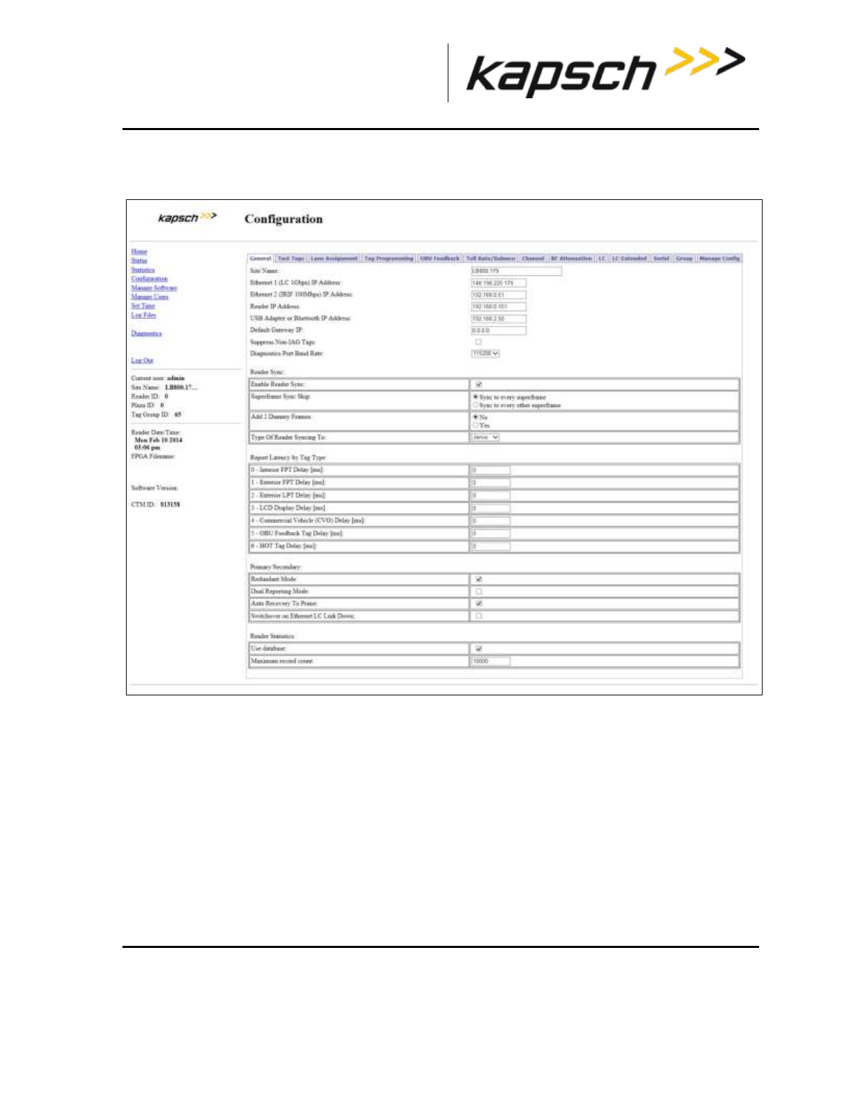
_
JANUS® Multi-Protocol Reader Ver. 2: Maintenance Instructions
Confidential UM 360463-202: A12 (Draft) Page 237 of 291
© Kapsch TrafficCom Canada Inc. 2013
These drawings and specifications contain confidential and proprietary information and are the property of Kapsch TrafficCom Canada Inc. and are issued in strict
confidence and will be kept confidential and used solely for the purpose intended and for no other purpose and shall not be transmitted, reproduced, copied, and/or
used as the basis for manufacture or sale of apparatus unless otherwise agreed to in writing by Kapsch TrafficCom Canada Inc.
FILE: MPR2_OPERATIONS_AND_MAINTENANCE-MANUAL_REV A12.DOCX 05/08/2014 11:24
Kapsch TrafficCom
1. Select the Configuration link on the left side panel.
Result: The following screen appears.
2. Click the Test Tags tab.
Result: The following screen appears.
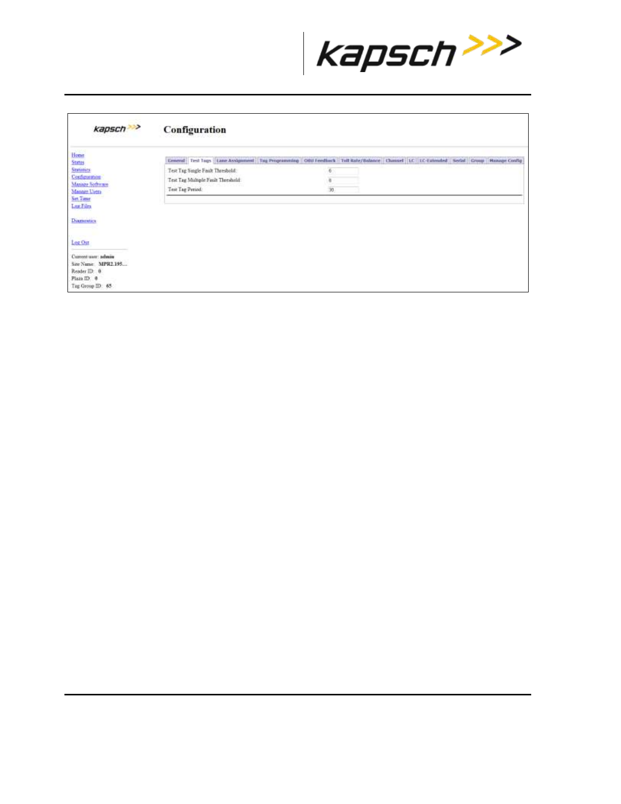
_
JANUS® Multi-Protocol Reader Ver. 2: Maintenance Instructions
Confidential UM 360463-202: A12 (Draft) Page 238 of 291
© Kapsch TrafficCom Canada Inc. 2013
These drawings and specifications contain confidential and proprietary information and are the property of Kapsch TrafficCom Canada Inc. and are issued in strict
confidence and will be kept confidential and used solely for the purpose intended and for no other purpose and shall not be transmitted, reproduced, copied, and/or
used as the basis for manufacture or sale of apparatus unless otherwise agreed to in writing by Kapsch TrafficCom Canada Inc.
FILE: MPR2_OPERATIONS_AND_MAINTENANCE-MANUAL_REV A12.DOCX 05/08/2014 11:24
Kapsch TrafficCom
3. Select the Test Tag State check box to enable tag testing for the appropriate RF channel(s).
4. Enter the number of consecutive test tag faults that cause a channel to be considered bad in the Test
Tag Single Fault Threshold text box.
Note: This should be set to 5 or higher.
5. Enter the number of bad channels that will trigger an automatic switchover, if the SPM redundancy switch
is in AUTO, in the Test Tag Multiple Fault Threshold text box.
Note: This value must be less than or equal to the number of RF channels equipped with test tags.
6. Enter the period of time between test tag checks, in seconds, in the Test Tag Period check box.
Note: This should be set between 30 and 90 seconds.
7. Press Enter or select a different tab to accept .
New firmware
Periodically, Kapsch Service will release a new version of the Reader firmware. The firmware name
indicates the year, month, day, and revision number of the release.
This procedure outlines how to upload the new firmware to the Reader so it can then be activated.
Uploading new firmware
Prerequisites: A service laptop containing a copy of the latest firmware is connected to either the
Ethernet 1 or a USB port and then logged into the CTM web interface.
You must have Software Management permissions.
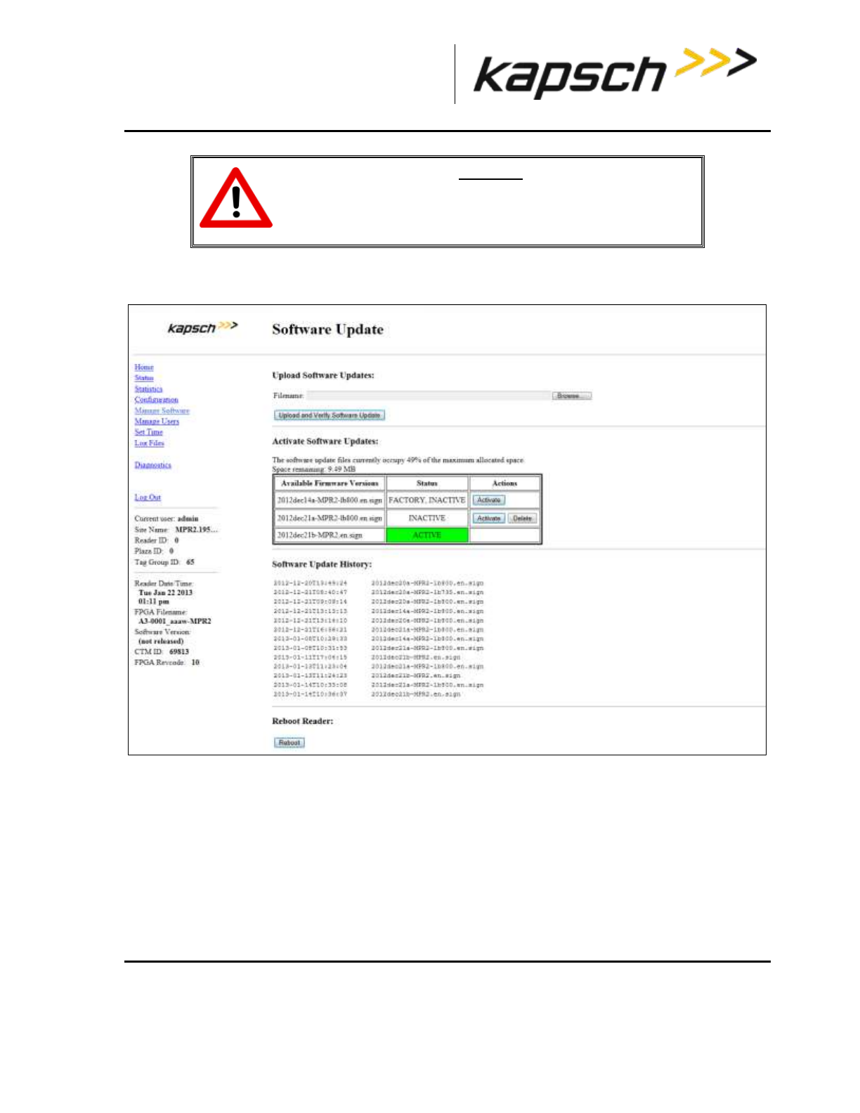
_
JANUS® Multi-Protocol Reader Ver. 2: Maintenance Instructions
Confidential UM 360463-202: A12 (Draft) Page 239 of 291
© Kapsch TrafficCom Canada Inc. 2013
These drawings and specifications contain confidential and proprietary information and are the property of Kapsch TrafficCom Canada Inc. and are issued in strict
confidence and will be kept confidential and used solely for the purpose intended and for no other purpose and shall not be transmitted, reproduced, copied, and/or
used as the basis for manufacture or sale of apparatus unless otherwise agreed to in writing by Kapsch TrafficCom Canada Inc.
FILE: MPR2_OPERATIONS_AND_MAINTENANCE-MANUAL_REV A12.DOCX 05/08/2014 11:24
Kapsch TrafficCom
CAUTION:
On a redundant Reader, ensure that the redundant side has no
fault conditions and all lane controller links are functioning
1. Select the Manage Software link from the left panel of the screen.
Result: The following Software Update page appears.
Note: Ensure that the new firmware version is more recent than the active firmware version
2. Check the Space remaining to ensure there is enough Reader memory to load the new firmware.
3. If there is not enough Reader memory, delete an older, inactive version of the firmware (see Deleting
firmware, page 242).
4. Click the Browse button to select the new firmware file saved on the computer.
5. Click the Upload and Verify Software Update button, then click Yes to confirm.
Result: The firmware will upload from the computer to the Reader. After the firmware has finished
uploading to the Reader, the firmware appears in the table of available firmware versions as INACTIVE.
To begin using the new firmware, activate the firmware (see Activating new firmware).

_
JANUS® Multi-Protocol Reader Ver. 2: Maintenance Instructions
Confidential UM 360463-202: A12 (Draft) Page 240 of 291
© Kapsch TrafficCom Canada Inc. 2013
These drawings and specifications contain confidential and proprietary information and are the property of Kapsch TrafficCom Canada Inc. and are issued in strict
confidence and will be kept confidential and used solely for the purpose intended and for no other purpose and shall not be transmitted, reproduced, copied, and/or
used as the basis for manufacture or sale of apparatus unless otherwise agreed to in writing by Kapsch TrafficCom Canada Inc.
FILE: MPR2_OPERATIONS_AND_MAINTENANCE-MANUAL_REV A12.DOCX 05/08/2014 11:24
Kapsch TrafficCom
Activating new firmware
The currently active firmware version becomes inactive once another firmware version is activated. All
numbered callouts in parenthesis refer to Figure 7-2.
The following procedures outline the steps for activating an inactive firmware version stored on the
Reader.
Prerequisites: You must have Software Management permissions.
The primary and secondary sides of the Reader are running normally.
The required firmware is uploaded to the Reader (see New firmware , page 238).
CAUTION:
Activating inactive factory firmware on a running system is not
recommended. The factory firmware may not be appropriate for
the specific application.
CAUTION: Redundant Reader
During firmware activation (typically less than 60 seconds) the
Reader will switch over to the other side to process and report
transactions, regardless of the position of the mode switch on the
SPM module. Ensure that the other side is running normally and
all lane controller links are functioning. The Reader will be unable
to process or report transactions if it is unable to switch over to
the other side.
CAUTION: Non-Redundant Reader
During firmware activation (typically less than 60 seconds), a non-
redundant Reader is unable to process or report transactions.
On the Primary side:
1. Save the current configuration file, (see Saving the Reader configuration, page 243).
2. From the Software Management page, identify the inactive firmware version to be activated in the
firmware version table ().
3. Click the corresponding Activate button () to activate the firmware. Click to acknowledge there will be
a delay before the firmware becomes active.
4. If necessary, restore the configuration file saved in step 1 (see Uploading a saved configuration, page
246).
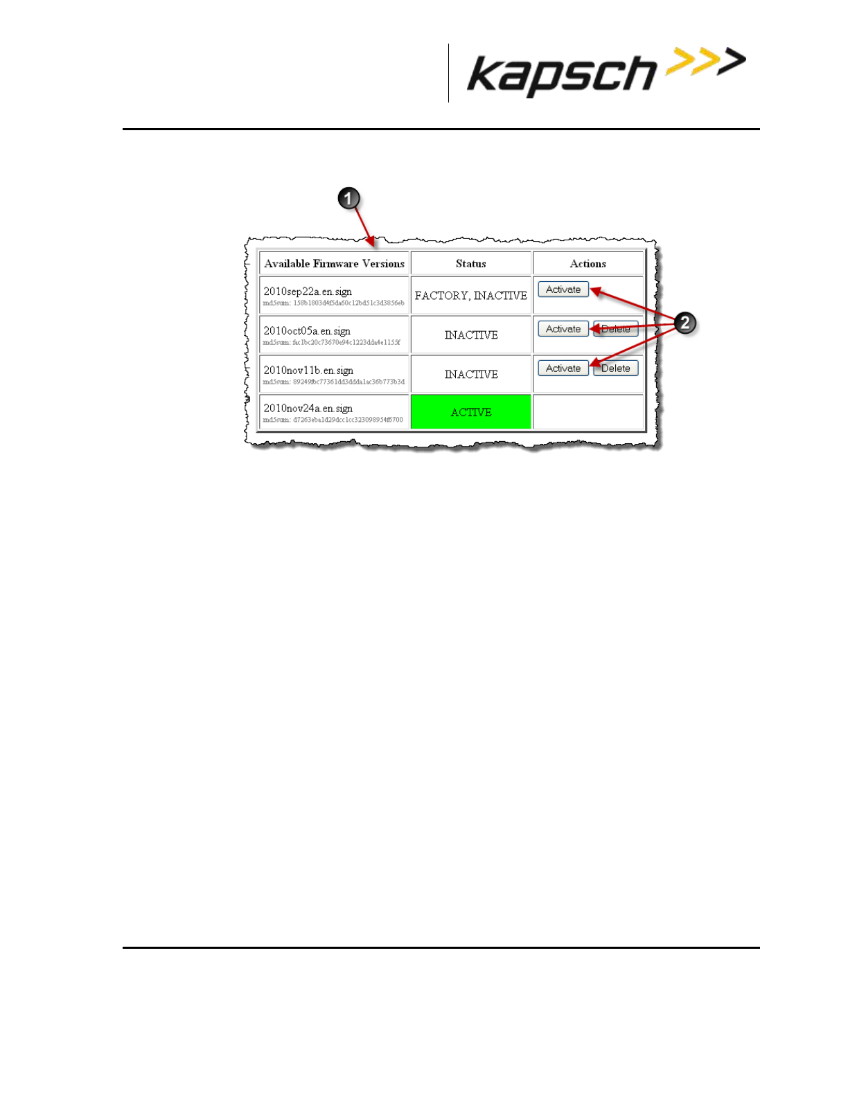
_
JANUS® Multi-Protocol Reader Ver. 2: Maintenance Instructions
Confidential UM 360463-202: A12 (Draft) Page 241 of 291
© Kapsch TrafficCom Canada Inc. 2013
These drawings and specifications contain confidential and proprietary information and are the property of Kapsch TrafficCom Canada Inc. and are issued in strict
confidence and will be kept confidential and used solely for the purpose intended and for no other purpose and shall not be transmitted, reproduced, copied, and/or
used as the basis for manufacture or sale of apparatus unless otherwise agreed to in writing by Kapsch TrafficCom Canada Inc.
FILE: MPR2_OPERATIONS_AND_MAINTENANCE-MANUAL_REV A12.DOCX 05/08/2014 11:24
Kapsch TrafficCom
Figure 7-2: Activating Firmware
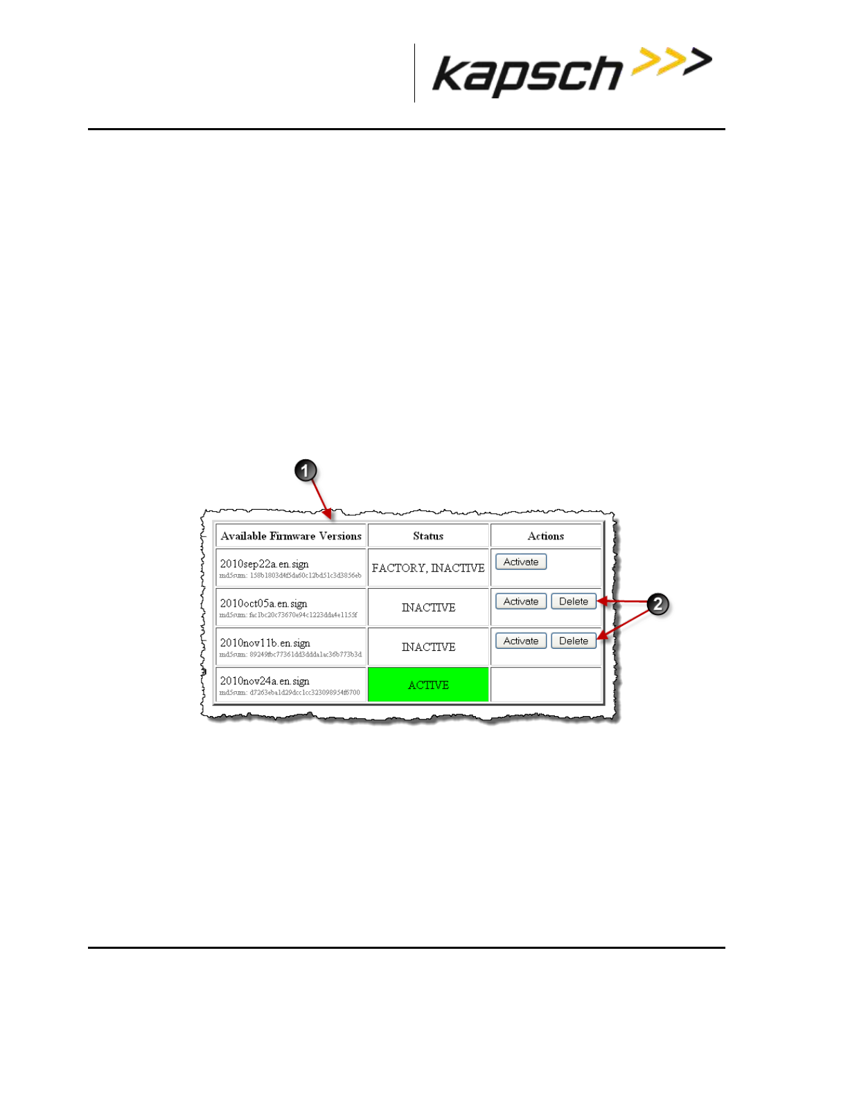
_
JANUS® Multi-Protocol Reader Ver. 2: Maintenance Instructions
Confidential UM 360463-202: A12 (Draft) Page 242 of 291
© Kapsch TrafficCom Canada Inc. 2013
These drawings and specifications contain confidential and proprietary information and are the property of Kapsch TrafficCom Canada Inc. and are issued in strict
confidence and will be kept confidential and used solely for the purpose intended and for no other purpose and shall not be transmitted, reproduced, copied, and/or
used as the basis for manufacture or sale of apparatus unless otherwise agreed to in writing by Kapsch TrafficCom Canada Inc.
FILE: MPR2_OPERATIONS_AND_MAINTENANCE-MANUAL_REV A12.DOCX 05/08/2014 11:24
Kapsch TrafficCom
On the Secondary side:
1. Repeat steps 1 through 4 for the secondary side, ensuring the same firmware version is active for the
primary and secondary side.
Deleting firmware
The Factory firmware and active firmware cannot be deleted. All callouts refer to Figure 7-3. This
procedure outlines the steps for deleting an inactive firmware version stored on the Reader.
Prerequisites: You must have Software Management permissions.
1. From the Software Management page, identify the inactive firmware version to be deleted in the
firmware version table ().
2. Click the corresponding Delete button (). Click Yes to confirm. The firmware will be deleted and will no
longer appear in the firmware version table ().
Figure 7-3: Deleting firmware
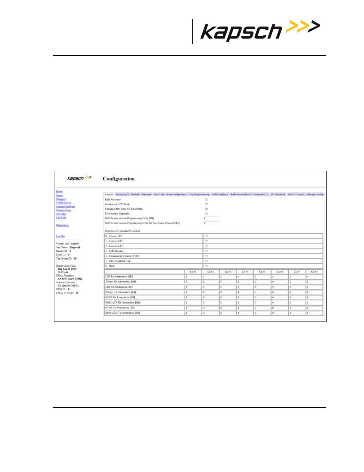
_
JANUS® Multi-Protocol Reader Ver. 2: Maintenance Instructions
Confidential UM 360463-202: A12 (Draft) Page 243 of 291
© Kapsch TrafficCom Canada Inc. 2013
These drawings and specifications contain confidential and proprietary information and are the property of Kapsch TrafficCom Canada Inc. and are issued in strict
confidence and will be kept confidential and used solely for the purpose intended and for no other purpose and shall not be transmitted, reproduced, copied, and/or
used as the basis for manufacture or sale of apparatus unless otherwise agreed to in writing by Kapsch TrafficCom Canada Inc.
FILE: MPR2_OPERATIONS_AND_MAINTENANCE-MANUAL_REV A12.DOCX 05/08/2014 11:24
Kapsch TrafficCom
Saving the Reader configuration
Each CTM has a unique configuration file stored on its CFM. This configuration file can be downloaded
and saved to a computer. Use a saved configuration file to do the following.
Quickly configure another Reader requiring the same or similar configuration.
Restore the Reader to a known configuration.
Troubleshoot problems by comparing the current configuration to past configurations.
This procedure outlines the steps for saving the Reader configuration to a service laptop which is
logged into a CTM.
Prerequisites: A service laptop connected to Ethernet 1 or a USB port of the CTM and accessing the
CTM web interface. Refer to Connecting a service laptop to the Reader, page 40.
1. Click the Configuration link on the left side panel.
Result: The following screen appears.
1. Click the Manage Config tab on the Configuration page.
Result: The following screen appears.
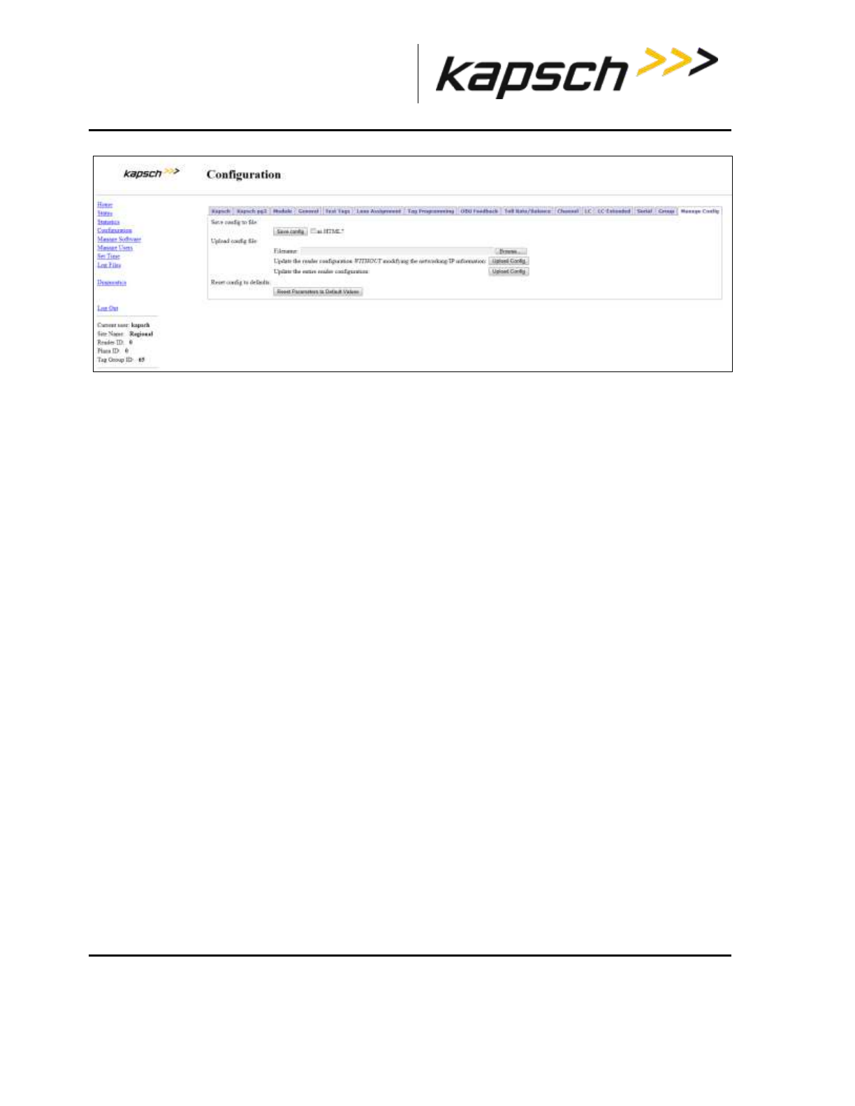
_
JANUS® Multi-Protocol Reader Ver. 2: Maintenance Instructions
Confidential UM 360463-202: A12 (Draft) Page 244 of 291
© Kapsch TrafficCom Canada Inc. 2013
These drawings and specifications contain confidential and proprietary information and are the property of Kapsch TrafficCom Canada Inc. and are issued in strict
confidence and will be kept confidential and used solely for the purpose intended and for no other purpose and shall not be transmitted, reproduced, copied, and/or
used as the basis for manufacture or sale of apparatus unless otherwise agreed to in writing by Kapsch TrafficCom Canada Inc.
FILE: MPR2_OPERATIONS_AND_MAINTENANCE-MANUAL_REV A12.DOCX 05/08/2014 11:24
Kapsch TrafficCom
2. Click the Save config button to save the new configuration.
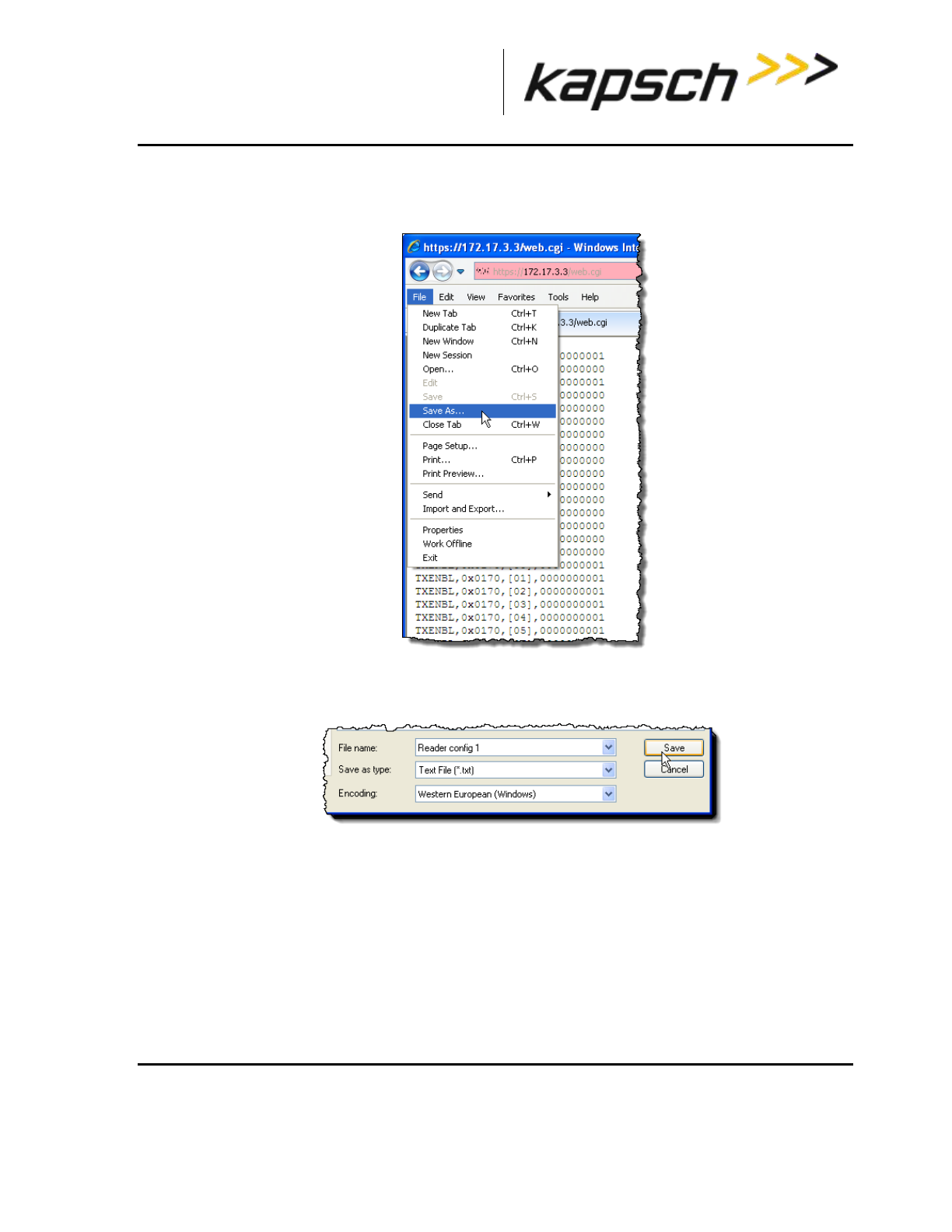
_
JANUS® Multi-Protocol Reader Ver. 2: Maintenance Instructions
Confidential UM 360463-202: A12 (Draft) Page 245 of 291
© Kapsch TrafficCom Canada Inc. 2013
These drawings and specifications contain confidential and proprietary information and are the property of Kapsch TrafficCom Canada Inc. and are issued in strict
confidence and will be kept confidential and used solely for the purpose intended and for no other purpose and shall not be transmitted, reproduced, copied, and/or
used as the basis for manufacture or sale of apparatus unless otherwise agreed to in writing by Kapsch TrafficCom Canada Inc.
FILE: MPR2_OPERATIONS_AND_MAINTENANCE-MANUAL_REV A12.DOCX 05/08/2014 11:24
Kapsch TrafficCom
If using Internet Explorer:
1. From the Internet Explorer File menu, select Save As. Select Yes to confirm, if prompted.
2. Select or create the destination folder, enter a unique file name, and select Text File as the file type.
3. Click Save.
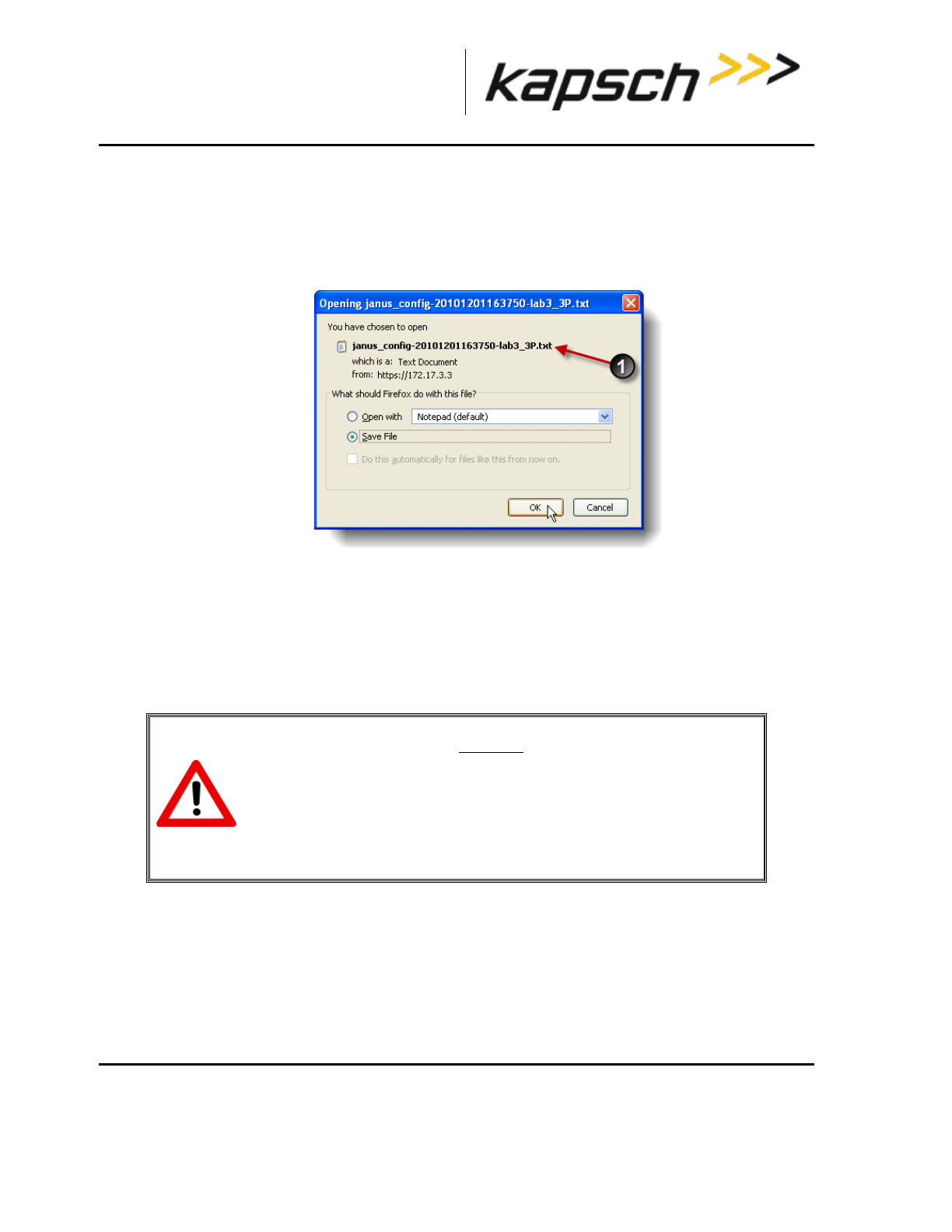
_
JANUS® Multi-Protocol Reader Ver. 2: Maintenance Instructions
Confidential UM 360463-202: A12 (Draft) Page 246 of 291
© Kapsch TrafficCom Canada Inc. 2013
These drawings and specifications contain confidential and proprietary information and are the property of Kapsch TrafficCom Canada Inc. and are issued in strict
confidence and will be kept confidential and used solely for the purpose intended and for no other purpose and shall not be transmitted, reproduced, copied, and/or
used as the basis for manufacture or sale of apparatus unless otherwise agreed to in writing by Kapsch TrafficCom Canada Inc.
FILE: MPR2_OPERATIONS_AND_MAINTENANCE-MANUAL_REV A12.DOCX 05/08/2014 11:24
Kapsch TrafficCom
If using Firefox:
1. Select Save File. Note the configuration filename () that is automatically generated.
2. Click OK.
Result: The configuration file will be saved as a text file in the default Firefox download location.
Uploading a saved configuration
Uploading a saved configuration will overwrite the current Reader configuration. There are two options
for uploading a saved configuration: updating all configuration settings except for the IP settings, or
updating all configuration settings including the IP settings. All callouts refer to Figure 7-4.
Prerequisites: A service laptop connected to Ethernet 1 or a USB port of the CTM and accessing the
CTM web interface.Refer to Connecting a service laptop to the Reader, page 40. A version of the
configuration file to be loaded is saved on a service laptop connected to the Reader.
CAUTION:
Improper modification of configuration parameters may adversely
affect system operation. The default values may not be appropriate
for the specific application. It is the system integrator’s responsibility
to tailor the configuration parameters to the specific operating
environment.
1. From the Manage Config tab on the Configuration page, click the Browse button () to locate the
configuration file on the service laptop to be uploaded.
2. If uploading all configuration settings to the Reader without changing the IP addresses settings, click the
first Upload Config button ().
3. If uploading all configuration settings to the Reader, including the IP addresses, click the second Upload
Config button ().
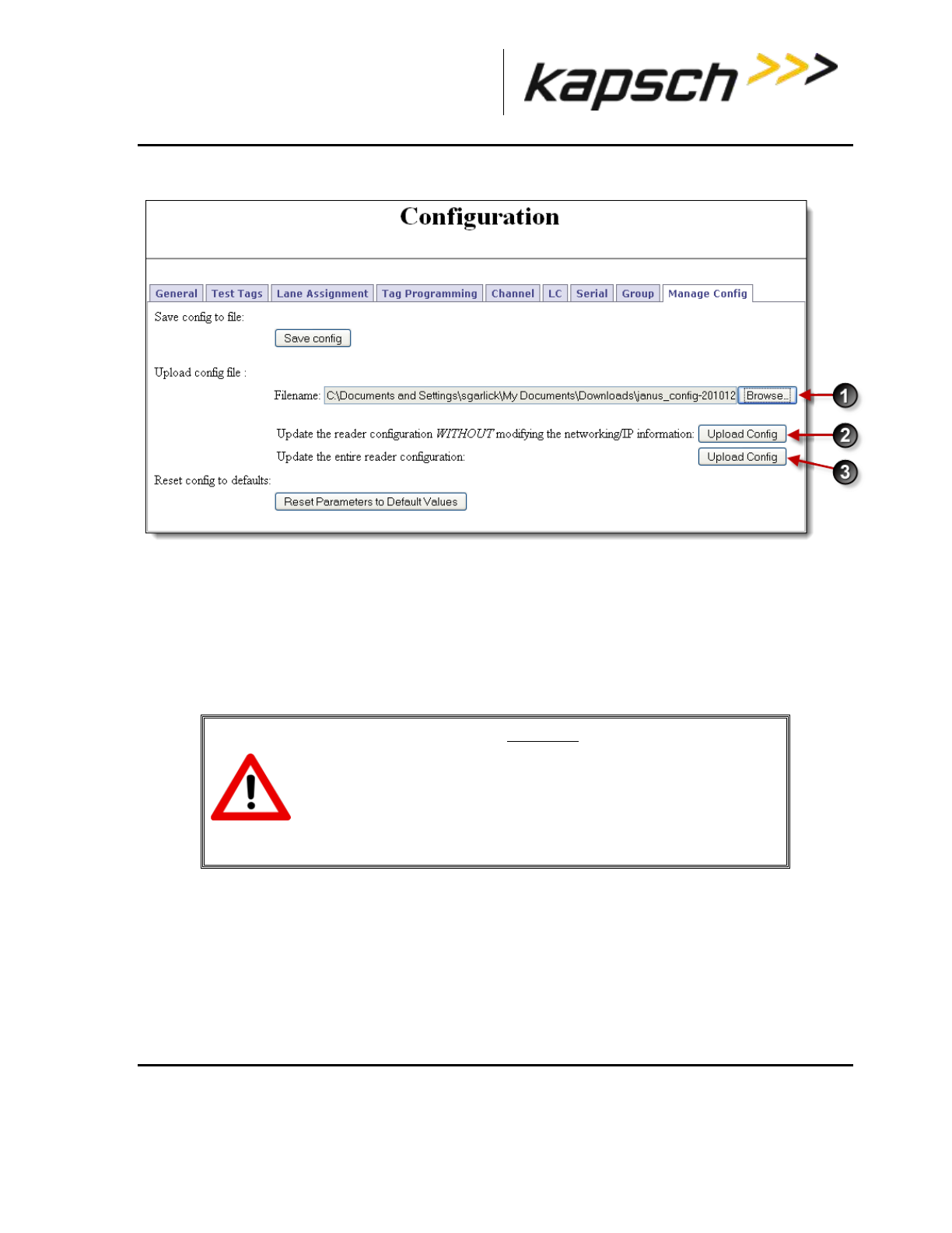
_
JANUS® Multi-Protocol Reader Ver. 2: Maintenance Instructions
Confidential UM 360463-202: A12 (Draft) Page 247 of 291
© Kapsch TrafficCom Canada Inc. 2013
These drawings and specifications contain confidential and proprietary information and are the property of Kapsch TrafficCom Canada Inc. and are issued in strict
confidence and will be kept confidential and used solely for the purpose intended and for no other purpose and shall not be transmitted, reproduced, copied, and/or
used as the basis for manufacture or sale of apparatus unless otherwise agreed to in writing by Kapsch TrafficCom Canada Inc.
FILE: MPR2_OPERATIONS_AND_MAINTENANCE-MANUAL_REV A12.DOCX 05/08/2014 11:24
Kapsch TrafficCom
Figure 7-4: The Manage Config tab on the Configuration page
Resetting the Reader configuration to the factory default
Certain field service tests use the factory default configuration. This procedure outlines how to restore
the factory default values without changing the Reader IP addresses.
Prerequisites: A service laptop connected to Ethernet 1 or a USB port of the CTM and accessing the
CTM web interface. Refer to Connecting a service laptop to the Reader, page 40. Save the current
Reader configuration (Saving the Reader configuration, page 243).
CAUTION:
The factory default configuration should not be restored on a
running Reader. The factory firmware may not be appropriate for
the specific application. Save the current Reader configuration
before resetting the Reader configuration to the factory default.
1. Click on the Configuration link on the left side panel of the CTM web Interface.
Result: The following Configuration page appears.
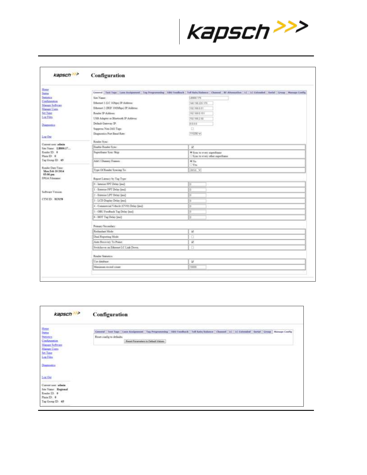
_
JANUS® Multi-Protocol Reader Ver. 2: Maintenance Instructions
Confidential UM 360463-202: A12 (Draft) Page 248 of 291
© Kapsch TrafficCom Canada Inc. 2013
These drawings and specifications contain confidential and proprietary information and are the property of Kapsch TrafficCom Canada Inc. and are issued in strict
confidence and will be kept confidential and used solely for the purpose intended and for no other purpose and shall not be transmitted, reproduced, copied, and/or
used as the basis for manufacture or sale of apparatus unless otherwise agreed to in writing by Kapsch TrafficCom Canada Inc.
FILE: MPR2_OPERATIONS_AND_MAINTENANCE-MANUAL_REV A12.DOCX 05/08/2014 11:24
Kapsch TrafficCom
2. Click the Manage Config tab.
Result: The following screen appears.
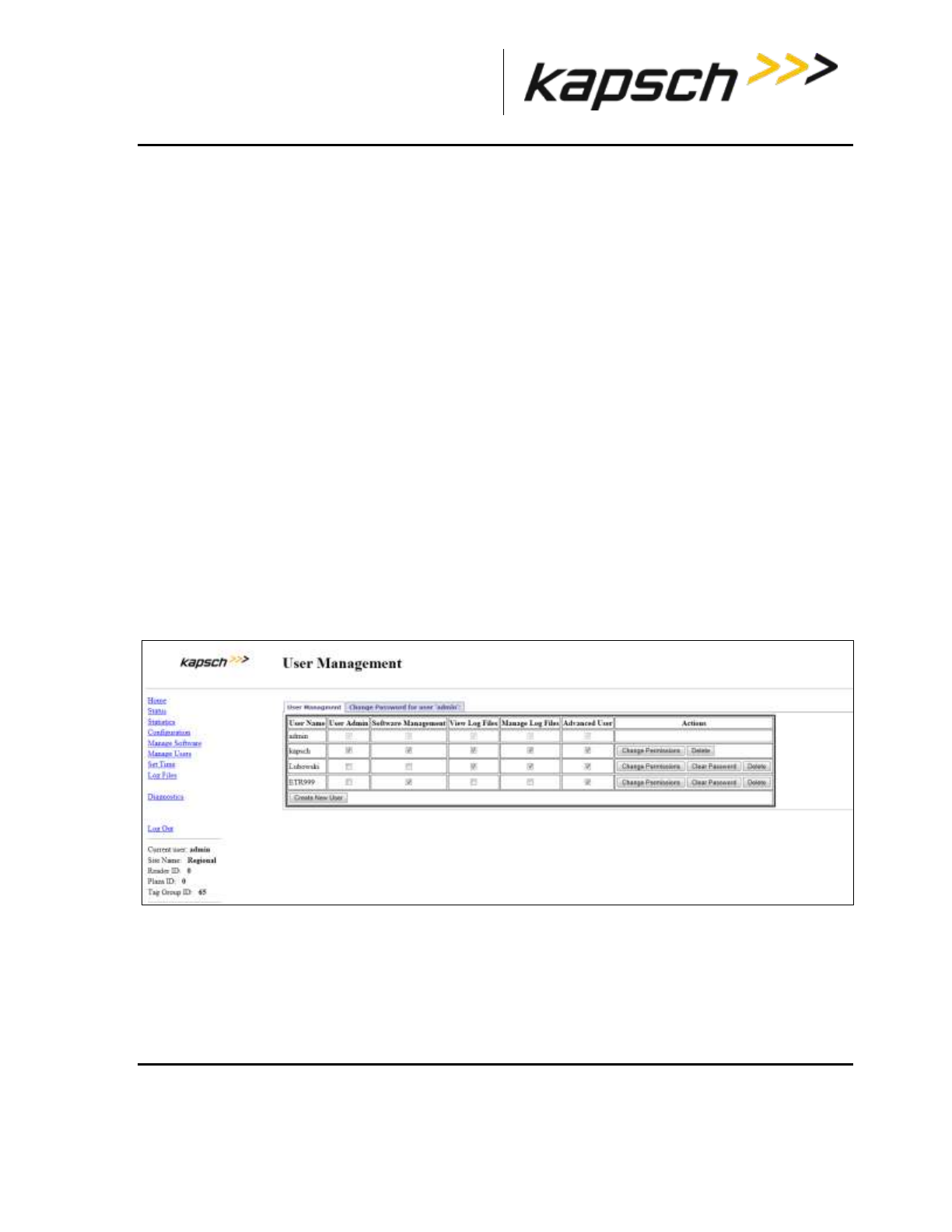
_
JANUS® Multi-Protocol Reader Ver. 2: Maintenance Instructions
Confidential UM 360463-202: A12 (Draft) Page 249 of 291
© Kapsch TrafficCom Canada Inc. 2013
These drawings and specifications contain confidential and proprietary information and are the property of Kapsch TrafficCom Canada Inc. and are issued in strict
confidence and will be kept confidential and used solely for the purpose intended and for no other purpose and shall not be transmitted, reproduced, copied, and/or
used as the basis for manufacture or sale of apparatus unless otherwise agreed to in writing by Kapsch TrafficCom Canada Inc.
FILE: MPR2_OPERATIONS_AND_MAINTENANCE-MANUAL_REV A12.DOCX 05/08/2014 11:24
Kapsch TrafficCom
3. Click the Reset Parameters to Default Values button.
Result: All configuration values, except for the Reader IP addresses, will change to the factory defaults.
Administration
User administration permissions are needed when a new user account needs to be created, when an
account needs to be changed, or deleted. The user can be given access to any combination of the five
following access areas.
User
Advanced user
Software management
User admin
Manage log files
Creating a new user
This procedure outlines how to create a new user account, create a password, and set the user
permissions.
Prerequisites: A service laptop connected to either the Ethernet 1 or a USB port of the CTM. Refer to
Connecting a service laptop to the Reader, page 40. You must have User Admin permissions.
1. Click on the Manage Users link on the left side panel
Result: The following screen appears.
2. A Create New User form will appear on the User Management tab.
3. Click the Create New User button.
Result: The following screen appears.
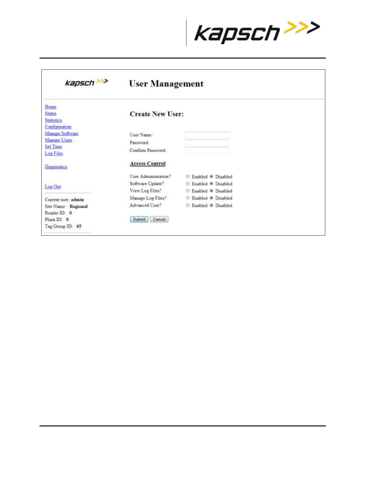
_
JANUS® Multi-Protocol Reader Ver. 2: Maintenance Instructions
Confidential UM 360463-202: A12 (Draft) Page 250 of 291
© Kapsch TrafficCom Canada Inc. 2013
These drawings and specifications contain confidential and proprietary information and are the property of Kapsch TrafficCom Canada Inc. and are issued in strict
confidence and will be kept confidential and used solely for the purpose intended and for no other purpose and shall not be transmitted, reproduced, copied, and/or
used as the basis for manufacture or sale of apparatus unless otherwise agreed to in writing by Kapsch TrafficCom Canada Inc.
FILE: MPR2_OPERATIONS_AND_MAINTENANCE-MANUAL_REV A12.DOCX 05/08/2014 11:24
Kapsch TrafficCom
4. Enter a unique user name in the User Name text box.
5. Enter the new user’s password in the Password and Confirm Password text boxes.
6. Select Enabled for any of the five access areas to give the user the appropriate permissions.
7. Click Submit to create the new user account and return to the User Management tab.
Note: If you decide not to create the user at this time, click Cancel to return to the User Management tab
Changing a user’s access permissions
A user’s access permissions are set when the user account is created. As a user’s responsibilities
change, they may need access to more or fewer areas of the Reader configuration. This procedure
outlines how to change the access permissions of an existing user.
Prerequisites: A service laptop connected to Ethernet 1 or a USB port of the CTM. Refer to Connecting
a service laptop to the Reader, page 40. You must have User Admin permissions.
1. Click on the Manage Users link on the left side panel
Result: The following screen appears.
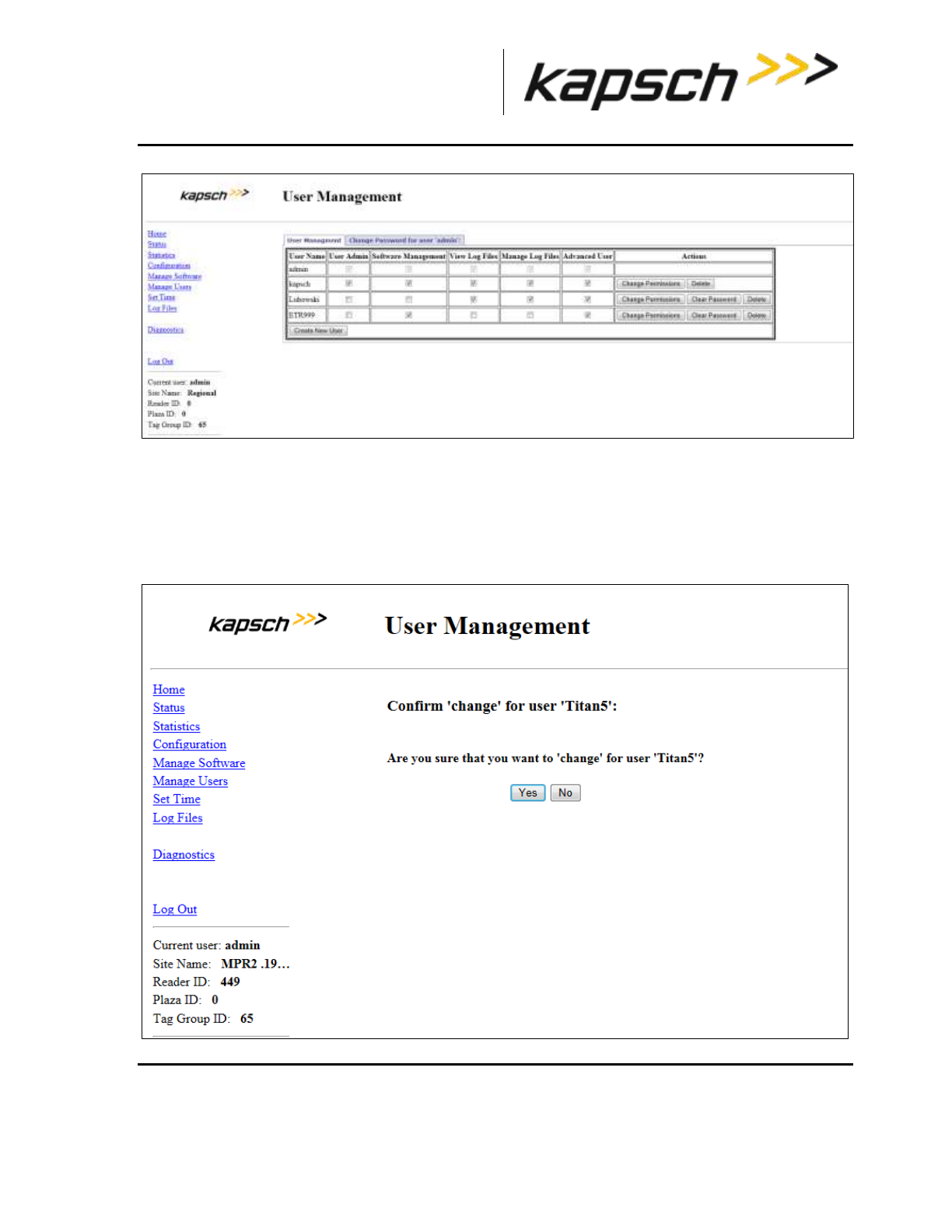
_
JANUS® Multi-Protocol Reader Ver. 2: Maintenance Instructions
Confidential UM 360463-202: A12 (Draft) Page 251 of 291
© Kapsch TrafficCom Canada Inc. 2013
These drawings and specifications contain confidential and proprietary information and are the property of Kapsch TrafficCom Canada Inc. and are issued in strict
confidence and will be kept confidential and used solely for the purpose intended and for no other purpose and shall not be transmitted, reproduced, copied, and/or
used as the basis for manufacture or sale of apparatus unless otherwise agreed to in writing by Kapsch TrafficCom Canada Inc.
FILE: MPR2_OPERATIONS_AND_MAINTENANCE-MANUAL_REV A12.DOCX 05/08/2014 11:24
Kapsch TrafficCom
2. Identify the user whose access permissions need changing.
3. Select the corresponding check box to give access to a particular area; clear the corresponding check box to
deny access.
Note: If you navigate away from the User Management page before clicking the Change Permissions button,
the access changes are not saved.
4. After the appropriate access changes are made, click the user’s corresponding Change Permissions button.
Result: The following screen appears.
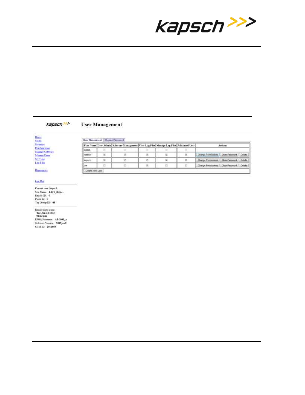
_
JANUS® Multi-Protocol Reader Ver. 2: Maintenance Instructions
Confidential UM 360463-202: A12 (Draft) Page 252 of 291
© Kapsch TrafficCom Canada Inc. 2013
These drawings and specifications contain confidential and proprietary information and are the property of Kapsch TrafficCom Canada Inc. and are issued in strict
confidence and will be kept confidential and used solely for the purpose intended and for no other purpose and shall not be transmitted, reproduced, copied, and/or
used as the basis for manufacture or sale of apparatus unless otherwise agreed to in writing by Kapsch TrafficCom Canada Inc.
FILE: MPR2_OPERATIONS_AND_MAINTENANCE-MANUAL_REV A12.DOCX 05/08/2014 11:24
Kapsch TrafficCom
5. Click Yes to confirm.
Result: The user access permissions update.
Deleting a user
Note: A deleted user will no longer be able to access the CTM web interface.
Prerequisites: A service laptop connected to Ethernet 1 or a USB port of the CTM. Refer to
Connecting a service laptop to the Reader, page 40. You must have User Admin permissions.
1. Click on the Manage Users link on the left side panel.
Result: The following screen appears.
2. Click the corresponding Delete button.
Result: A dialog box appears for delete confirmation.
3. Click Yes to confirm.
Verifying a computer is communicating with a specific CTM
Note: This test verifies the CTM that is being communicated with while using the web interface.
Prerequisites: A service laptop connected to Ethernet 1 or a USB port of the CTM and accessing the
CTM web interface. Refer to Connecting a service laptop to the Reader, page 40.
1. Click on the Configuration link on the left side panel of the CTM web Interface.
Result: The following Configuration page appears.
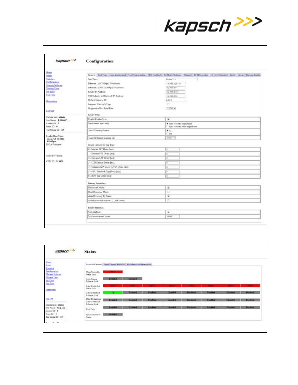
_
JANUS® Multi-Protocol Reader Ver. 2: Maintenance Instructions
Confidential UM 360463-202: A12 (Draft) Page 253 of 291
© Kapsch TrafficCom Canada Inc. 2013
These drawings and specifications contain confidential and proprietary information and are the property of Kapsch TrafficCom Canada Inc. and are issued in strict
confidence and will be kept confidential and used solely for the purpose intended and for no other purpose and shall not be transmitted, reproduced, copied, and/or
used as the basis for manufacture or sale of apparatus unless otherwise agreed to in writing by Kapsch TrafficCom Canada Inc.
FILE: MPR2_OPERATIONS_AND_MAINTENANCE-MANUAL_REV A12.DOCX 05/08/2014 11:24
Kapsch TrafficCom
2. Click the Status link on the left panel.
Result: The following screen appears.
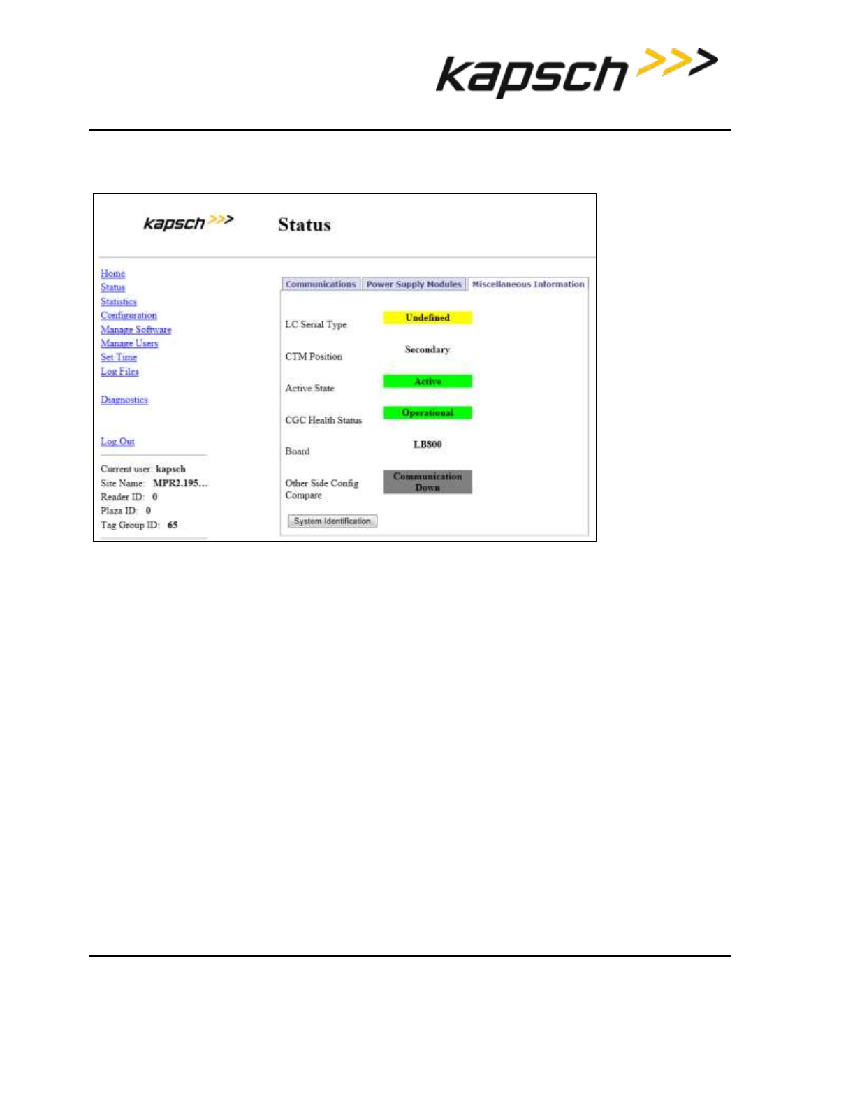
_
JANUS® Multi-Protocol Reader Ver. 2: Maintenance Instructions
Confidential UM 360463-202: A12 (Draft) Page 254 of 291
© Kapsch TrafficCom Canada Inc. 2013
These drawings and specifications contain confidential and proprietary information and are the property of Kapsch TrafficCom Canada Inc. and are issued in strict
confidence and will be kept confidential and used solely for the purpose intended and for no other purpose and shall not be transmitted, reproduced, copied, and/or
used as the basis for manufacture or sale of apparatus unless otherwise agreed to in writing by Kapsch TrafficCom Canada Inc.
FILE: MPR2_OPERATIONS_AND_MAINTENANCE-MANUAL_REV A12.DOCX 05/08/2014 11:24
Kapsch TrafficCom
3. Click the Miscellaneous Information tab
Result: The following screen appears.
4. Click the System Identification button.
Result: The CTM MC LED flashes green – red – amber – green three times.
Note: If the CTM MC LED does not flash correctly, the service laptop is not communicating with that CTM.
Using an NTP Server to synchronize the clocks of Readers in an IR network
Readers can use NTP servers to accurately regulate the time of all Readers in an IR network. This
procedure outlines how to enable NTP time synchronization, set IP addresses for the NTP servers, and
select the time zone for display purposes.
Note: NTP time sync can be used when a single reader is in use, as well as multiple readers.
Prerequisites: The Reader must be on a network connected to the Internet. A service laptop
connected to Ethernet 1 or a USB port of the CTM and accessing the CTM web interface. Refer to
Connecting a service laptop to the Reader, page 40.You must have Advanced User permissions.
1. Visit http://support.ntp.org/bin/view/Servers/StratumTwoTimeServers to see a list of NTP servers.
2. Identify an NTP server in your geographic region (the ISO column) that has an OpenAccess policy (the
AccessPolicy column).
3. Click on the host name of the NTP server (the HostName column). The ServerForm table appears.
4. Record the IP address of the NTP server.
Note: The following step is optional.
5. Repeat steps 2 through 4 to obtain a total of three (3) IP addresses, each from a different NTP server.
6. Click on the Set Time link on the left side panel of the CTM web interface.
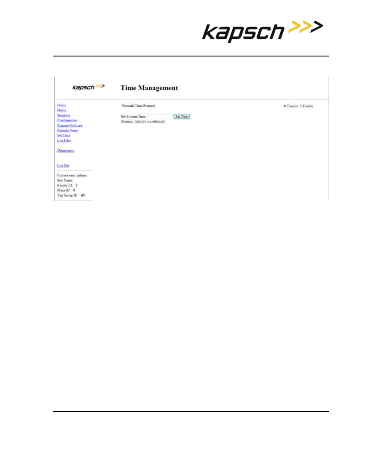
_
JANUS® Multi-Protocol Reader Ver. 2: Maintenance Instructions
Confidential UM 360463-202: A12 (Draft) Page 255 of 291
© Kapsch TrafficCom Canada Inc. 2013
These drawings and specifications contain confidential and proprietary information and are the property of Kapsch TrafficCom Canada Inc. and are issued in strict
confidence and will be kept confidential and used solely for the purpose intended and for no other purpose and shall not be transmitted, reproduced, copied, and/or
used as the basis for manufacture or sale of apparatus unless otherwise agreed to in writing by Kapsch TrafficCom Canada Inc.
FILE: MPR2_OPERATIONS_AND_MAINTENANCE-MANUAL_REV A12.DOCX 05/08/2014 11:24
Kapsch TrafficCom
Result: The following screen appears.
7. From the Time Management screen, select Enable to enable the Reader time updates from an NTP server.
8. Enter the three unique IP addresses recorded in step 4 in the NTP Server 1, 2 and 3 text boxes.
9. Select the appropriate time zone from the Time Zone drop-down box. This is for display purposes only.
10. Click the Update NTP Setting button.
Result: The first available NTP server updates the Reader time.
Manually setting the Reader time and date
The Reader time can be set manually when it is not part of an Inter-Reader network. This procedure
outlines how to set manually the Reader time.
Prerequisites: A service laptop connected to Ethernet 1 or a USB port of the CTM and accessing the
CTM web interface. Refer to Connecting a service laptop to the Reader, page 40.
1. Click the Set Time link on the left side of the panel.
Result: The following screen appears.
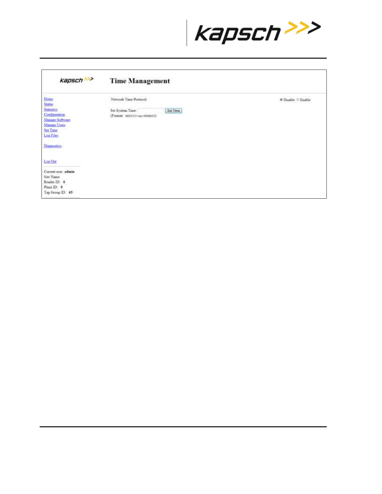
_
JANUS® Multi-Protocol Reader Ver. 2: Maintenance Instructions
Confidential UM 360463-202: A12 (Draft) Page 256 of 291
© Kapsch TrafficCom Canada Inc. 2013
These drawings and specifications contain confidential and proprietary information and are the property of Kapsch TrafficCom Canada Inc. and are issued in strict
confidence and will be kept confidential and used solely for the purpose intended and for no other purpose and shall not be transmitted, reproduced, copied, and/or
used as the basis for manufacture or sale of apparatus unless otherwise agreed to in writing by Kapsch TrafficCom Canada Inc.
FILE: MPR2_OPERATIONS_AND_MAINTENANCE-MANUAL_REV A12.DOCX 05/08/2014 11:24
Kapsch TrafficCom
2. Enter a numeric value for the date and time in the Set System Time field. The format is
‘MMDDYY<space>HHMMSS’, using a 24-hour clock.
3. Click the Set Time button.
Result: The Reader updates to the time entered in the field.
Logging transactions remotely via an Ethernet connection
Attention: Use this function only under the direction of Kapsch Service.
Monitoring OBU transactions as they occur via the DIAGNOSTIC PORT
Use the Diagnostics port to view OBU transactions as they occur. This can also be done from the CTM
web interface Diagnostics page.
Prerequisites: A service laptop connected to the Reader DIAGNOSTIC PORT using PuTTY or
HyperTerminal. Refer to Connecting a service laptop to the Reader, page 40.
see Using PuTTY to connect to the DIAGNOSTIC PORT, page 260, or,
see Using HyperTerminal to connect to the DIAGNOSTIC PORT, page 260.
Note: The operator must ensure that there is only one active connection to diag1 for any given CTM.
Having more than one simultaneous diag1 connection per CTM is not supported.
1. Press the Enter key a few times until the command prompt is displayed.
2. At the login: prompt, enter diag1 as the user id and diag1 as the password.
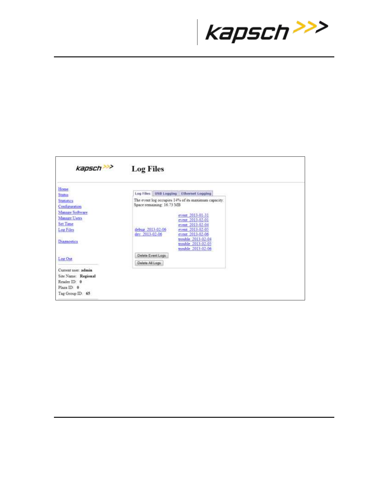
_
JANUS® Multi-Protocol Reader Ver. 2: Maintenance Instructions
Confidential UM 360463-202: A12 (Draft) Page 257 of 291
© Kapsch TrafficCom Canada Inc. 2013
These drawings and specifications contain confidential and proprietary information and are the property of Kapsch TrafficCom Canada Inc. and are issued in strict
confidence and will be kept confidential and used solely for the purpose intended and for no other purpose and shall not be transmitted, reproduced, copied, and/or
used as the basis for manufacture or sale of apparatus unless otherwise agreed to in writing by Kapsch TrafficCom Canada Inc.
FILE: MPR2_OPERATIONS_AND_MAINTENANCE-MANUAL_REV A12.DOCX 05/08/2014 11:24
Kapsch TrafficCom
Note: Any OBU transactions will be displayed as they occur.
Saving Reader log files to a computer
This procedure outlines how to save any log file currently saved on the Reader to a computer.
Prerequisites: A service laptop connected to Ethernet 1 or a USB port of the CTM and accessing the
CTM web interface. Refer to Connecting a service laptop to the Reader, page 40. You must have View
Log Files and Manage Log Files permissions.
1. Select the Log Files link on the left side panel of the CTM web interface.
Result: The following screen appears.
2. Right-click on the log file you want to save from the list.
Result: The following screen appears.
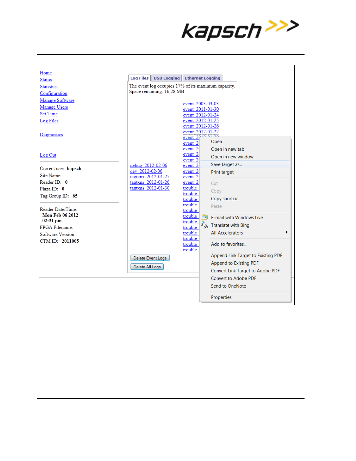
_
JANUS® Multi-Protocol Reader Ver. 2: Maintenance Instructions
Confidential UM 360463-202: A12 (Draft) Page 258 of 291
© Kapsch TrafficCom Canada Inc. 2013
These drawings and specifications contain confidential and proprietary information and are the property of Kapsch TrafficCom Canada Inc. and are issued in strict
confidence and will be kept confidential and used solely for the purpose intended and for no other purpose and shall not be transmitted, reproduced, copied, and/or
used as the basis for manufacture or sale of apparatus unless otherwise agreed to in writing by Kapsch TrafficCom Canada Inc.
FILE: MPR2_OPERATIONS_AND_MAINTENANCE-MANUAL_REV A12.DOCX 05/08/2014 11:24
Kapsch TrafficCom
3. Click Save Target As… (Internet Explorer), Save Link As… (Firefox), or Save Link As… (Chrome) as
applicable.
4. In the pop-up window, select a save location, and then click the Save button.
Result: The file downloads to the computer.
Manually saving a Reader log file to a USB flash drive
This procedure outlines how to save any log file currently saved on the Reader to a USB memory stick.
Prerequisites: A USB memory stick is inserted into one of the CTM USB ports.
You must have View Log Files and Manage Log Files permissions.

_
JANUS® Multi-Protocol Reader Ver. 2: Maintenance Instructions
Confidential UM 360463-202: A12 (Draft) Page 259 of 291
© Kapsch TrafficCom Canada Inc. 2013
These drawings and specifications contain confidential and proprietary information and are the property of Kapsch TrafficCom Canada Inc. and are issued in strict
confidence and will be kept confidential and used solely for the purpose intended and for no other purpose and shall not be transmitted, reproduced, copied, and/or
used as the basis for manufacture or sale of apparatus unless otherwise agreed to in writing by Kapsch TrafficCom Canada Inc.
FILE: MPR2_OPERATIONS_AND_MAINTENANCE-MANUAL_REV A12.DOCX 05/08/2014 11:24
Kapsch TrafficCom
From the USB Logging tab on the Log Files page:
1. Click the Copy Log Files to USB device button.
2. Click the Safely Remove Hardware and Eject Media icon on the taskbar tray and select Eject USB device.
3. Remove the USB memory stick.
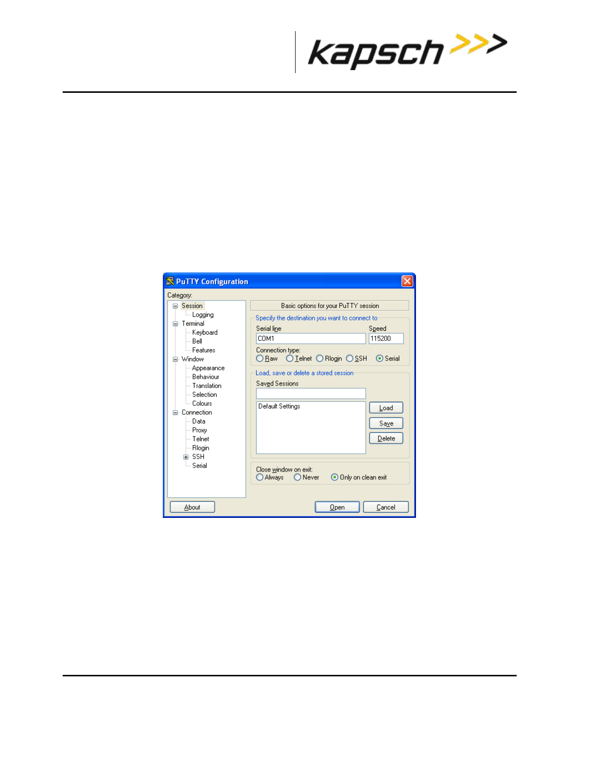
_
JANUS® Multi-Protocol Reader Ver. 2: Appendix
Confidential UM 360463-202: A12 (Draft) Page 260 of 291
© Kapsch TrafficCom Canada Inc. 2013
These drawings and specifications contain confidential and proprietary information and are the property of Kapsch TrafficCom Canada Inc. and are issued in strict
confidence and will be kept confidential and used solely for the purpose intended and for no other purpose and shall not be transmitted, reproduced, copied, and/or
used as the basis for manufacture or sale of apparatus unless otherwise agreed to in writing by Kapsch TrafficCom Canada Inc.
FILE: MPR2_OPERATIONS_AND_MAINTENANCE-MANUAL_REV A12.DOCX 05/08/2014 11:24
Kapsch TrafficCom
Appendix A Miscellaneous
Using PuTTY to connect to the DIAGNOSTIC PORT
1. Launch PuTTY.
2. Select Serial as your Connection Type.
3. Select the computer COM port that is connected to the Diagnostic Port.
4. Enter 115200 in the Speed text box.
5. Click Open.
Result: The following configuration screen appears.
6. Press Enter a few times until the login prompt appears.
Using HyperTerminal to connect to the DIAGNOSTIC PORT
1. Go to Start Run.
2. Type hypertrm, and then click OK.
3. In the Connection Description pop-up, enter a session name and then click OK.
4. In the Connect To pop-up, select the COM port that is connected to the Diagnostic Port from the
Connect Using drop-down box.
5. Click OK.
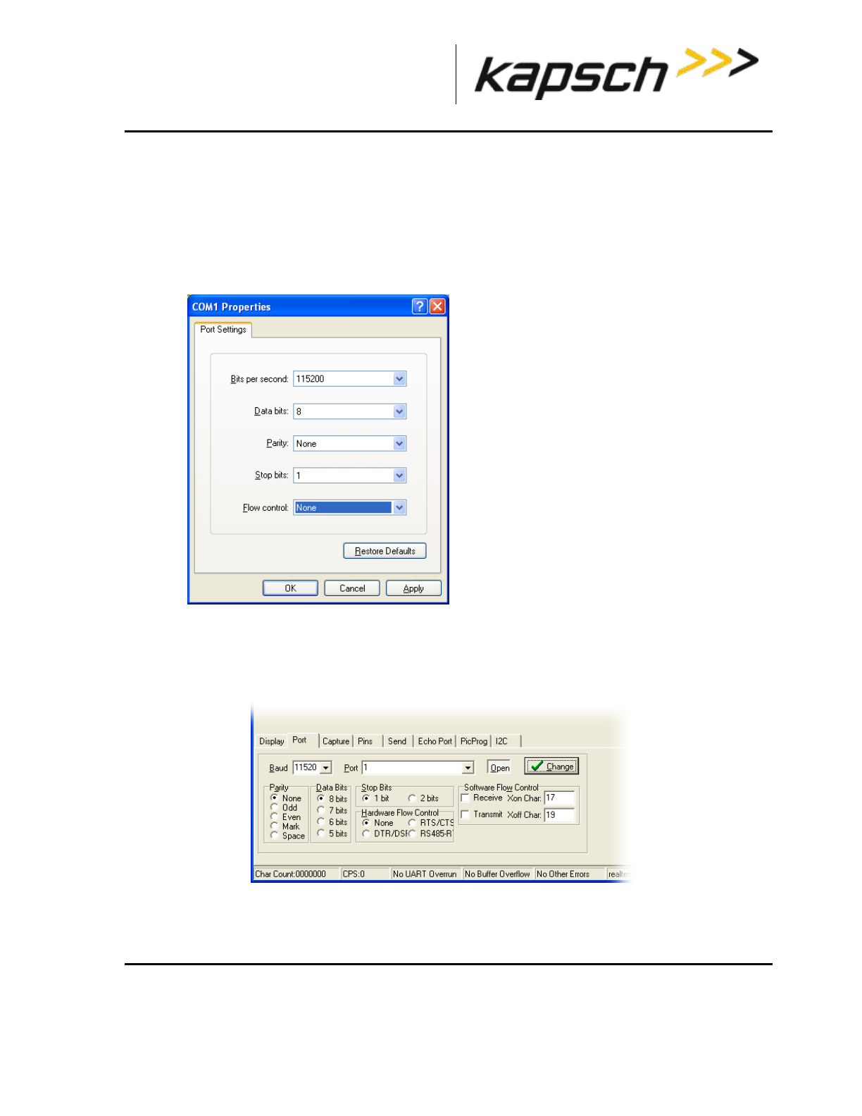
_
JANUS® Multi-Protocol Reader Ver. 2: Appendix
Confidential UM 360463-202: A12 (Draft) Page 261 of 291
© Kapsch TrafficCom Canada Inc. 2013
These drawings and specifications contain confidential and proprietary information and are the property of Kapsch TrafficCom Canada Inc. and are issued in strict
confidence and will be kept confidential and used solely for the purpose intended and for no other purpose and shall not be transmitted, reproduced, copied, and/or
used as the basis for manufacture or sale of apparatus unless otherwise agreed to in writing by Kapsch TrafficCom Canada Inc.
FILE: MPR2_OPERATIONS_AND_MAINTENANCE-MANUAL_REV A12.DOCX 05/08/2014 11:24
Kapsch TrafficCom
Using RealTerm to connect to the MRFM-S
1. Connect a serial cable from the MRFM LC COM port to a port on your computer.
2. Launch RealTerm.
3. From the Port tab, select 115200 from the Bits per second drop-down box,set Data Bits to 8, set Parity
to None, Stop Bits to 1, Flow Control to None.
Example: The following example is shown.
4. Select the COM port number of the computer port you connected to in Step 1 from the Port drop-down
box.
5. Click the Change button.
6. From the Display tab, select Binary from the Display As column.
7. MRFM-S data now displays in the display pane in the upper half of the RealTerm window.

_
JANUS® Multi-Protocol Reader Ver. 2: Appendix
Confidential UM 360463-202: A12 (Draft) Page 262 of 291
© Kapsch TrafficCom Canada Inc. 2013
These drawings and specifications contain confidential and proprietary information and are the property of Kapsch TrafficCom Canada Inc. and are issued in strict
confidence and will be kept confidential and used solely for the purpose intended and for no other purpose and shall not be transmitted, reproduced, copied, and/or
used as the basis for manufacture or sale of apparatus unless otherwise agreed to in writing by Kapsch TrafficCom Canada Inc.
FILE: MPR2_OPERATIONS_AND_MAINTENANCE-MANUAL_REV A12.DOCX 05/08/2014 11:24
Kapsch TrafficCom
Accessing Documentation
You can access the documentation package for the JANUS® Multi-Protocol Reader Ver. 2 online at
http://dds.kapsch.ca
A Username and Password can be obtained from Kapsch Service.
The documentation package includes the following.
Bill of Materials
Assembly Drawings
Schematic Drawings
Parts Specifications (for purchased items)
Operator and Maintenance Manuals
Installation Instructions
Training slides
Software Design Documents: Context Diagrams, Data Flows
As-built installation drawings (services)

_
JANUS® Multi-Protocol Reader Ver. 2: Appendix
Confidential UM 360463-202: A12 (Draft) Page 263 of 291
© Kapsch TrafficCom Canada Inc. 2013
These drawings and specifications contain confidential and proprietary information and are the property of Kapsch TrafficCom Canada Inc. and are issued in strict
confidence and will be kept confidential and used solely for the purpose intended and for no other purpose and shall not be transmitted, reproduced, copied, and/or
used as the basis for manufacture or sale of apparatus unless otherwise agreed to in writing by Kapsch TrafficCom Canada Inc.
FILE: MPR2_OPERATIONS_AND_MAINTENANCE-MANUAL_REV A12.DOCX 05/08/2014 11:24
Kapsch TrafficCom
Technical Specifications and Pin outs
JANUS® Multi-Protocol Reader Ver. 2 Technical Specifications
Operation subject to FCC Site licensing (per FCC Part 90, Subpart M)
Dimensions (excluding enclosure)
Height = 17.5 inch
Width = 19.06 inch
Depth = 11.30 inch
Weight (excluding enclosure)
Redundant Reader, with all slots filled: 63 lbs. (Not including MRFM-S)
Enclosure Requirements
NEMA 4 rated
Operating Temperature Range
-29.2F to +165.2F (-34C to +74C) For operation above 55oC a 300CFM fan tray is required.
Power Requirements
300W @ 110VAC, UL/CSA power supply.
Minimum of two, 3-prong IEC-320 receptacles (not supplied).
PSM Ratings
95-135 VAC, 60 +/- 2 Hz, 5A.
One capable of supplying full load on redundant systems.
Software
Latest release available at delivery. Reader ships with default configuration settings.
Memory Capacity
400,000 buffered transactions.
RF Channel Capacity
Lane-based channels: maximum of 8.
ORT channels: maximum of 5.

_
JANUS® Multi-Protocol Reader Ver. 2: Appendix
Confidential UM 360463-202: A12 (Draft) Page 264 of 291
© Kapsch TrafficCom Canada Inc. 2013
These drawings and specifications contain confidential and proprietary information and are the property of Kapsch TrafficCom Canada Inc. and are issued in strict
confidence and will be kept confidential and used solely for the purpose intended and for no other purpose and shall not be transmitted, reproduced, copied, and/or
used as the basis for manufacture or sale of apparatus unless otherwise agreed to in writing by Kapsch TrafficCom Canada Inc.
FILE: MPR2_OPERATIONS_AND_MAINTENANCE-MANUAL_REV A12.DOCX 05/08/2014 11:24
Kapsch TrafficCom
NEMA 4 Enclosure Specifications
Kapsch TrafficCom Field Cabinet Part Numbers
Left hinged: 800127-101
Right hinged: 800127-102
Dimension
Height = 36 inch
Width = 30 inch
Depth = 20 inch
Enclosure Requirements
A 6 to 8-inch clearance between the top and bottom of the Reader and enclosure.
Located for ready maintenance access.
Location limited by maximum RF and Synchronization cable run length.
Construction
-Aluminum with stainless steel components
-Neoprene gasket
-Installed a 19-inch equipment rack for Reader mounting
-Universally keyed lock
Penetrations
Must not allow moisture or condensation to run onto electronics or power cables.
Kapsch TrafficCom warranty extends to manufacturer defects as delivered but does not cover
environments, locations, or penetrations that invalidate the NEMA 4 rating.
Deference is made to any specifications used by the agency to govern NEMA 4 enclosures on its
roadways.
Grounding
Use AWG 8 wire to connect to the earth – ground system.
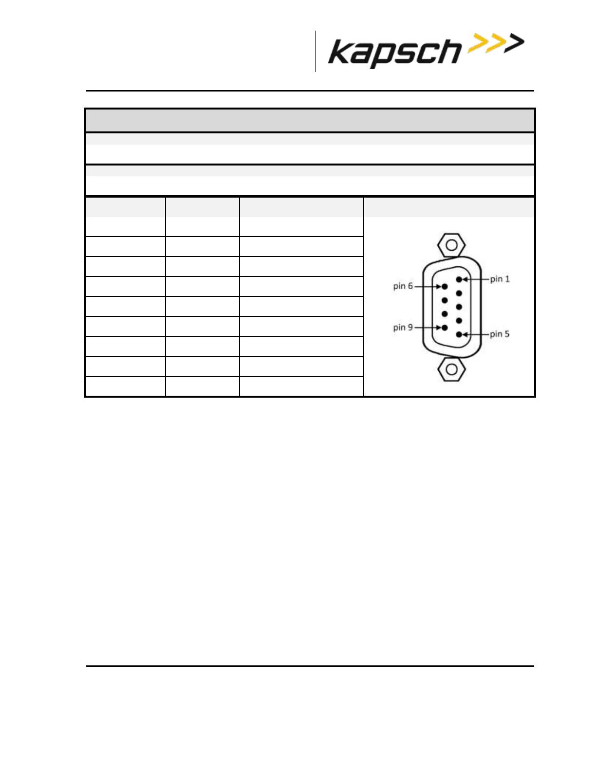
_
JANUS® Multi-Protocol Reader Ver. 2: Appendix
Confidential UM 360463-202: A12 (Draft) Page 265 of 291
© Kapsch TrafficCom Canada Inc. 2013
These drawings and specifications contain confidential and proprietary information and are the property of Kapsch TrafficCom Canada Inc. and are issued in strict
confidence and will be kept confidential and used solely for the purpose intended and for no other purpose and shall not be transmitted, reproduced, copied, and/or
used as the basis for manufacture or sale of apparatus unless otherwise agreed to in writing by Kapsch TrafficCom Canada Inc.
FILE: MPR2_OPERATIONS_AND_MAINTENANCE-MANUAL_REV A12.DOCX 05/08/2014 11:24
Kapsch TrafficCom
CTM Diagnostic Port pin out
Connector Type
Data Communications Equipment (DCE) pin assignment, 9–pin male connector.
Lightning Suppression
Not required.
Pin
Number
Signal
Description
Diagram
1
DCD
Carrier Detect input
2
RXD
Receive Data input
3
TXD
Transmit Data output
4
n/c
5
GND
Logic Ground
6
n/c
7
RTS
Request to Send output
8
CTS
Clear to Send input
9
n/c

_
JANUS® Multi-Protocol Reader Ver. 2: Appendix
Confidential UM 360463-202: A12 (Draft) Page 266 of 291
© Kapsch TrafficCom Canada Inc. 2013
These drawings and specifications contain confidential and proprietary information and are the property of Kapsch TrafficCom Canada Inc. and are issued in strict
confidence and will be kept confidential and used solely for the purpose intended and for no other purpose and shall not be transmitted, reproduced, copied, and/or
used as the basis for manufacture or sale of apparatus unless otherwise agreed to in writing by Kapsch TrafficCom Canada Inc.
FILE: MPR2_OPERATIONS_AND_MAINTENANCE-MANUAL_REV A12.DOCX 05/08/2014 11:24
Kapsch TrafficCom
CTM Ethernet Ports 1 and 2 pin out
Connector Type
8 pin RJ45 female
Lightning Suppression
Recommended on all pins.
Pin
Number
Signal
Description
Diagram
1
BI_DA+
Bi-directional pair A +
2
BI_DA-
Bi-directional pair A -
3
BI_DB+
Bi-directional pair B +
4
BI_DC+
Bi-directional pair C +
5
BI_DC-
Bi-directional pair C -
6
BI_DB-
Bi-directional pair B -
7
BI_DD+
Bi-directional pair D +
8
BI_DD-
Bi-directional pair D -

_
JANUS® Multi-Protocol Reader Ver. 2: Appendix
Confidential UM 360463-202: A12 (Draft) Page 267 of 291
© Kapsch TrafficCom Canada Inc. 2013
These drawings and specifications contain confidential and proprietary information and are the property of Kapsch TrafficCom Canada Inc. and are issued in strict
confidence and will be kept confidential and used solely for the purpose intended and for no other purpose and shall not be transmitted, reproduced, copied, and/or
used as the basis for manufacture or sale of apparatus unless otherwise agreed to in writing by Kapsch TrafficCom Canada Inc.
FILE: MPR2_OPERATIONS_AND_MAINTENANCE-MANUAL_REV A12.DOCX 05/08/2014 11:24
Kapsch TrafficCom
SPM terminal block connections
Connector Type
Terminal block
Lightning Suppression
Recommended for all signal wires.
Terminal
Number
Signal
Description
Diagram
1
CGND
chassis ground, shield
2
R-
Sync Rx (RS-422 -)
3
R+
Sync Rx (RS-422 +)
4
T+
Sync Tx (RS-422 +)
5
T-
Sync Tx (RS-422 -)
6
CGND
chassis ground, shield
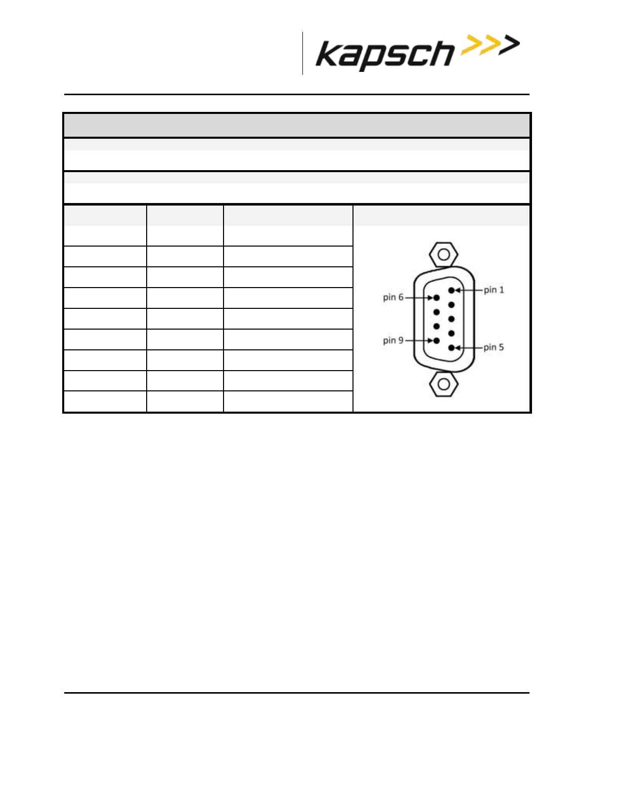
_
JANUS® Multi-Protocol Reader Ver. 2: Appendix
Confidential UM 360463-202: A12 (Draft) Page 268 of 291
© Kapsch TrafficCom Canada Inc. 2013
These drawings and specifications contain confidential and proprietary information and are the property of Kapsch TrafficCom Canada Inc. and are issued in strict
confidence and will be kept confidential and used solely for the purpose intended and for no other purpose and shall not be transmitted, reproduced, copied, and/or
used as the basis for manufacture or sale of apparatus unless otherwise agreed to in writing by Kapsch TrafficCom Canada Inc.
FILE: MPR2_OPERATIONS_AND_MAINTENANCE-MANUAL_REV A12.DOCX 05/08/2014 11:24
Kapsch TrafficCom
LPM RS-232 COM Port pin out
Connector Type
Data Terminal Equipment (DTE) pin assignment, DB9
Lightning Suppression
Recommended on pins 2, 3, 7, 8.
Pin
Number
Signal
Description
Diagram
1
DCD
Data Carrier Detect
2
TXD
Transmit data output
3
RXD
Receive data input
4
DTR
Data Terminal Ready
5
SGND
Signal ground
6
DSR
Data Set Ready
7
RTS
Ready to Send
8
CTS
Clear To Send
9
CGND
Chassis ground

_
JANUS® Multi-Protocol Reader Ver. 2: Appendix
Confidential UM 360463-202: A12 (Draft) Page 269 of 291
© Kapsch TrafficCom Canada Inc. 2013
These drawings and specifications contain confidential and proprietary information and are the property of Kapsch TrafficCom Canada Inc. and are issued in strict
confidence and will be kept confidential and used solely for the purpose intended and for no other purpose and shall not be transmitted, reproduced, copied, and/or
used as the basis for manufacture or sale of apparatus unless otherwise agreed to in writing by Kapsch TrafficCom Canada Inc.
FILE: MPR2_OPERATIONS_AND_MAINTENANCE-MANUAL_REV A12.DOCX 05/08/2014 11:24
Kapsch TrafficCom
LPM RS-422 COM Port pin out
Connector Type
Data Terminal Equipment (DTE) pin assignment, DB9
Lightning Suppression
Recommended on pins 1, 2, 3, 4.
Pin
Number
Signal
Description
Diagram
1
TXD+
Transmit data output
2
TXD-
Transmit data output
3
RXD+
Receive data output
4
RXD-
Receive data input
5
NC
6
NC
7
NC
8
NC
9
NC

_
JANUS® Multi-Protocol Reader Ver. 2: Appendix
Confidential UM 360463-202: A12 (Draft) Page 270 of 291
© Kapsch TrafficCom Canada Inc. 2013
These drawings and specifications contain confidential and proprietary information and are the property of Kapsch TrafficCom Canada Inc. and are issued in strict
confidence and will be kept confidential and used solely for the purpose intended and for no other purpose and shall not be transmitted, reproduced, copied, and/or
used as the basis for manufacture or sale of apparatus unless otherwise agreed to in writing by Kapsch TrafficCom Canada Inc.
FILE: MPR2_OPERATIONS_AND_MAINTENANCE-MANUAL_REV A12.DOCX 05/08/2014 11:24
Kapsch TrafficCom
Antenna Specifications
Antenna
IAG-1
IAG-3
P/N
800260-011
800260-015
Lane Kit #
801692-019
Description
3x3 patch
3x4 dipole array
Width
(inch)
34.75
34.5
Length
(inch)
31.75
21.25
Thickness
(in inches)
2.3
3.13
Weight1
(lbs)
33
19
Mounting
horizontal
horizontal
Application
standard width
or ORT lane
Standard Width or
ORT lane
Note: Mounting information is provided as a guideline.
Weight specified is applicable to the antenna structure only i.e. it does not include mounting hardware.

_
JANUS® Multi-Protocol Reader Ver. 2: Appendix
Confidential UM 360463-202: A12 (Draft) Page 271 of 291
© Kapsch TrafficCom Canada Inc. 2013
These drawings and specifications contain confidential and proprietary information and are the property of Kapsch TrafficCom Canada Inc. and are issued in strict
confidence and will be kept confidential and used solely for the purpose intended and for no other purpose and shall not be transmitted, reproduced, copied, and/or
used as the basis for manufacture or sale of apparatus unless otherwise agreed to in writing by Kapsch TrafficCom Canada Inc.
FILE: MPR2_OPERATIONS_AND_MAINTENANCE-MANUAL_REV A12.DOCX 05/08/2014 11:24
Kapsch TrafficCom
Antenna Environmental Specifications
Operating Temperature: -34C to 74C
Vibration:
Frequency Displacement
Below 1 Hz 10 inch sway
1-4 Hz 1 inch sway
4-10 Hz 0.1 amplitude
11-15 Hz 0.03 amplitude
16-25 Hz 0.02 amplitude
26-30 Hz 0.01 amplitude
31-40 Hz 0.005 amplitude
41-50 Hz 0.003 amplitude
Shock (all direction): 15 G, 11 ms saw tooth
Wind: 160 mph
Peak Displacement: 6 inches
RF Cable Specifications
Kapsch TrafficCom IVHS recommends the following options for RF feedline cables.
Cable P/N
Manufacturer
Loss/100ft
(dB)
LMR-400DB
Times Microwave
3.966
LMR-600DB
Times Microwave
2.542
LMR 900DB
Times Microwave
1.725
LDF4-50A
Andrews
2.1
The maximum cable length is limited by the permitted cable signal loss. The maximum cable signal
loss is based on the protocols selected and is limited to the lowest value in the table below of all
protocols enabled.

_
JANUS® Multi-Protocol Reader Ver. 2: Appendix
Confidential UM 360463-202: A12 (Draft) Page 272 of 291
© Kapsch TrafficCom Canada Inc. 2013
These drawings and specifications contain confidential and proprietary information and are the property of Kapsch TrafficCom Canada Inc. and are issued in strict
confidence and will be kept confidential and used solely for the purpose intended and for no other purpose and shall not be transmitted, reproduced, copied, and/or
used as the basis for manufacture or sale of apparatus unless otherwise agreed to in writing by Kapsch TrafficCom Canada Inc.
FILE: MPR2_OPERATIONS_AND_MAINTENANCE-MANUAL_REV A12.DOCX 05/08/2014 11:24
Kapsch TrafficCom
Protocol
Maximum
cable loss
(dB)
TDM - IAG
8
ISO18000-6C
8
ISO18000-6B
4
SeGo
4
Allegro
4
10374/ATA/AAR S-918
4
Connectors: Use cable assembly tools recommended by the cable manufacturer.
Cable splicing: No splices are allowed, must be a continuous run
Minimum Bend Radius: See Manufacturers recommendation
Finished connection must be weatherproofed using self-amalgamating tape
Cable that run underground or may be submersed in water must be installed in conduit with no other
cables capable of inducing RFI or EMI.
Synchronization cable specifications
Belden 9730 or 89730 cable or equivalent as determined by Kapsch TrafficCom engineering. Detailed
specifications available from manufacturer.
An example of the wiring detail is shown in Figure 5-9: Synchronization circuit schematic for three
Readers, page 159. This cable must be run in conduit and should not be run with other cables capable
of inducing RFI or EMI.
Maximum Sync Cable Length
2000 feet (607 meters) max length, sum of all Readers cable segments to hub
1500 feet (457 meters) max length, any one Reader cable segment to hub
Sync Cable Requirements
Temperature: as required for operating environment
Environmental: as required for operating environment (must be waterproof if immersion is possible)
Capacitance: 30 pF/ft or less
Sync Wire: 3 twisted pairs (2 active, 1 spare), shielded, single or multiple drain
Wire gauge: 24 AWG (minimum)

_
JANUS® Multi-Protocol Reader Ver. 2: Appendix
Confidential UM 360463-202: A12 (Draft) Page 273 of 291
© Kapsch TrafficCom Canada Inc. 2013
These drawings and specifications contain confidential and proprietary information and are the property of Kapsch TrafficCom Canada Inc. and are issued in strict
confidence and will be kept confidential and used solely for the purpose intended and for no other purpose and shall not be transmitted, reproduced, copied, and/or
used as the basis for manufacture or sale of apparatus unless otherwise agreed to in writing by Kapsch TrafficCom Canada Inc.
FILE: MPR2_OPERATIONS_AND_MAINTENANCE-MANUAL_REV A12.DOCX 05/08/2014 11:24
Kapsch TrafficCom
Terminal Block
Temperature and Environmental: as required for operating environment
Number of terminals: [4 X (number of Readers in the sync group) plus 4] e.g. 3 Readers require
(4x3)+4 = 16
Connection: See the example diagram of a three-Reader sync hub connection inFigure 5-9, page 159.
Spares and Tools
The following table lists the recommended spares for the JANUS reader and the Lane Kits.
Part Number
Description
801638-001
Configuration module - CFM
801701-003
Lane port module, RS422 - LPM
801701-002
Lane port module, RS232 - LPM
802311-001
Power supply module, primary - PSM
802311-002
Power supply module, secondary - PSM
307865-020
Fuse, time lag, 10A, 500V, power supply main input
801693-001
Sync port module, 2-wire RS485-SPM
801693-002
Sync port module, 4-wire RS485 - SPM
801693-003
Sync port module, 4-wire RS422 - SPM
802284-TAB
Controller module, RS422 - CTM
802284-TAB
Controller module, RS232 - CTM
802344-001
Lane kit, IAG-3
800260-011
Antenna, IAG-1
800260-015
Antenna, IAG-3
800125-001
Adapter cable, RF

_
JANUS® Multi-Protocol Reader Ver. 2: Appendix
Confidential UM 360463-202: A12 (Draft) Page 274 of 291
© Kapsch TrafficCom Canada Inc. 2013
These drawings and specifications contain confidential and proprietary information and are the property of Kapsch TrafficCom Canada Inc. and are issued in strict
confidence and will be kept confidential and used solely for the purpose intended and for no other purpose and shall not be transmitted, reproduced, copied, and/or
used as the basis for manufacture or sale of apparatus unless otherwise agreed to in writing by Kapsch TrafficCom Canada Inc.
FILE: MPR2_OPERATIONS_AND_MAINTENANCE-MANUAL_REV A12.DOCX 05/08/2014 11:24
Kapsch TrafficCom
Part Number
Description
802295-TAB
MRFM-S module
Test Equipment
Two-way radios
Measuring device (Tape rule, Wheel)
Lane marking materials (paint or other)
Plumb bob (25ft. line length)
Electronic Level (digital display)
Tool kits, appropriate cables, connectors etc.
Test Vehicles
Bucket / Lift Platform Truck
Passenger Vehicle (Type to be determined by Kapsch Engineering)

_
JANUS® Multi-Protocol Reader Ver. 2: Appendix
Confidential UM 360463-202: A12 (Draft) Page 275 of 291
© Kapsch TrafficCom Canada Inc. 2013
These drawings and specifications contain confidential and proprietary information and are the property of Kapsch TrafficCom Canada Inc. and are issued in strict
confidence and will be kept confidential and used solely for the purpose intended and for no other purpose and shall not be transmitted, reproduced, copied, and/or
used as the basis for manufacture or sale of apparatus unless otherwise agreed to in writing by Kapsch TrafficCom Canada Inc.
FILE: MPR2_OPERATIONS_AND_MAINTENANCE-MANUAL_REV A12.DOCX 05/08/2014 11:24
Kapsch TrafficCom
Reference Documents
Doc number
Title
ICD 360430-111
Interface Control Document for the Next Generation Reader External
Hardware Interface
322704-TAB
Calibration Procedures
322710-077
Gold Transponder and Production Tester Calibration and Maintenance
Procedure
801850-002
Front Mount Exterior (FME) Transponder Mounting Instructions for
passenger vehicles
801850-004
G4 Interior Transponder Mounting Instructions
801850-005
Front Mount Exterior (FME) Transponder Roof Mounting Instructions for
trucks and buses
801850-006
Motorcycle Front Mount Exterior (FME) Transponder Mounting Instructions
801850-008
G4F Feedback Interior Transponder Mounting Instructions
801850-012
G4 Transponder Secure Mount Bracket Mounting Instructions
801850-014
G4P Permanent Interior Transponder Mounting Instructions
801850-015
Flat Pack Transponder (FPT) Mounting Instructions
801850-016
Roof-Mount Flat Pack Transponder (FPT) Mounting Instructions for trucks
and buses
801850-018
Commercial Vehicle Operator (CVO) Self-Test Transponder Mounting
Instructions
801850-019
Front Mount Exterior (FME) Transponder Front Mounting Instructions for
trucks and buses
801850-020
Motorcycle Flat Pack Transponder (FPT) Mounting Instructions
Other commercial Documents
RuggedMC™ RMC40 Installation Guide
Belden 89730 Multi-Conductor - Multi-Pair Snake Cable Detailed Specifications and Technical Data
Belden 9730 Paired - Multi-Pair Snake Cable Detailed Specifications and Technical Data

_
JANUS® Multi-Protocol Reader Ver. 2: Appendix
Confidential UM 360463-202: A12 (Draft) Page 276 of 291
© Kapsch TrafficCom Canada Inc. 2013
These drawings and specifications contain confidential and proprietary information and are the property of Kapsch TrafficCom Canada Inc. and are issued in strict
confidence and will be kept confidential and used solely for the purpose intended and for no other purpose and shall not be transmitted, reproduced, copied, and/or
used as the basis for manufacture or sale of apparatus unless otherwise agreed to in writing by Kapsch TrafficCom Canada Inc.
FILE: MPR2_OPERATIONS_AND_MAINTENANCE-MANUAL_REV A12.DOCX 05/08/2014 11:24
Kapsch TrafficCom
Acronyms and Synonyms
Term
Meaning
Reference or example
AC
Alternating current
AM
Amplitude modulation
AWG
American wire gauge
BGR
Badger
a Kapsch TrafficCom manufactured Reader assembly
BOM
Bill Of Material
A parts list identifying individual components in the
assembly of a system module
BPS
Bits per second
Data rate, or transmission speed
CAT
Category
an Ethernet cable type
CF
Compact flash
a memory storage type
CFM
Configuration Module
Non-volatile storage device containing the Reader
configuration
CGC
Channel Group Controller
Module
PWA board to handle the Manchester encoded RF
protocol between the transponder and the Reader
CGND
Chassis ground
Common grounding mechanism for components within
an enclosure or chassis. Typically earth grounded. The
earth ground system must comply with the U.S.
National Electrical Code (NEC) requirements for a
grounding electrode.
CMOS
complementary metal-oxide
semiconductor
a technology for manufacturing ICs
COM
communications
ex. COM port
COM
Communication module
In the Badger Reader, the Communication module
provides the RS232/RS422 interface between the
Reader and the Lane Controller. Note: Replaced by
the LPM in the JANUS Reader..
computer
the service laptop computer or
the LC host computer
CPS
Cycles per second
Hertz
CPU
Central processing unit
CRA
Cross Reader Algorithm
Badger Reader legacy algorithm (tag based) used to
suppress duplicate transaction reporting to the Lane
Controller
CTM
Controller Module
A plug-in module containing an assembly of CGC2 and
MC

_
JANUS® Multi-Protocol Reader Ver. 2: Appendix
Confidential UM 360463-202: A12 (Draft) Page 277 of 291
© Kapsch TrafficCom Canada Inc. 2013
These drawings and specifications contain confidential and proprietary information and are the property of Kapsch TrafficCom Canada Inc. and are issued in strict
confidence and will be kept confidential and used solely for the purpose intended and for no other purpose and shall not be transmitted, reproduced, copied, and/or
used as the basis for manufacture or sale of apparatus unless otherwise agreed to in writing by Kapsch TrafficCom Canada Inc.
FILE: MPR2_OPERATIONS_AND_MAINTENANCE-MANUAL_REV A12.DOCX 05/08/2014 11:24
Kapsch TrafficCom
Term
Meaning
Reference or example
CTS
Clear to send
RS232 pin assignment
DA
data
DB or dB
decibel(s)
unit of measurement of RF signal strength
DC
direct current
DCD
Data carrier detect
RS232 pin assignment
DCE
Data communications
equipment
RS232 port configuration, transmit is pin 2
deg.
degrees
DIN
Deutsches Institut für
Normung
German national standards organization
DSM
Distribution Module
Reader’s back plane carrying DC power distributions to
each module and signal connectivity between modules.
DSR
Data set ready
RS232 pin assignment
DTE
Data terminal equipment
RS232 port configuration, transmit is pin 3
DTR
Data terminal ready
RS232 pin assignment
EBX
embedded board expandable
form factor
compatible with legacy PC104 form factor
EIA
Electronic Industry
Association
EMI
Electromagnetic Interference
Disturbance to radio signals and electronic circuits due
to undesirable B-field emissions from an external
source. See also RFI.
EMP
Electromagnetic Pulse
Strong disturbance that negates the ability of all
exposed electronics in the affected area.
EN
enable
ESD
electro-static discharge
ESM
Ethernet Switch Module
Used to create an inter-Reader network of up to 3
Readers in ORT installations, improves Voting
ETC
Electronic Toll Collection
Collection of tolls using electronic mechanisms such as
RFID tags and Readers
FCC
Federal Communications
Commission
FDM
Frequency Domaine Module
An RF module that is able to scan multiple OBUs from
the frequency being emitted by them.

_
JANUS® Multi-Protocol Reader Ver. 2: Appendix
Confidential UM 360463-202: A12 (Draft) Page 278 of 291
© Kapsch TrafficCom Canada Inc. 2013
These drawings and specifications contain confidential and proprietary information and are the property of Kapsch TrafficCom Canada Inc. and are issued in strict
confidence and will be kept confidential and used solely for the purpose intended and for no other purpose and shall not be transmitted, reproduced, copied, and/or
used as the basis for manufacture or sale of apparatus unless otherwise agreed to in writing by Kapsch TrafficCom Canada Inc.
FILE: MPR2_OPERATIONS_AND_MAINTENANCE-MANUAL_REV A12.DOCX 05/08/2014 11:24
Kapsch TrafficCom
Term
Meaning
Reference or example
FME
Front Mount Exterior
An exterior tag in a weatherproof package mounted
using the front license plate mounting holes. This item
replaces the LPT tag
FPGA
Field Programmable Gate
Array
the FPGA file defines the bit stream
FPT
Flat Pack Transponder
An interior tag in flat package mounted on the inside of
the windshield
GND
ground
HS
handshake
HTTPS
Hypertext Transfer Protocol
Secure
Hz
Hertz
Cycles per second
I/O
input/output
IAG
Inter-Agency Group
A group of toll highway agencies regulating common
tag content and use
IC
Integrated circuit
ICD
Interface Control Document
Specification of the physical interface, protocol and file
formats used for messages sent between two
communications components.
ID
Identity or Identifier
Group ID in RF Channel configuration
IEC
International Electrotechnical
Commission
IEEE
Institute of Electrical and
Electronic Engineers
Worldwide non-profit professional organization that
makes voluntary, consensus-based, standards
IF
Interface
IP
Intellectual Property or
Internet Protocol
reference an asset or reference an address
IR
Inter-Reader
IRIF
Inter-Reader interface
An Ethernet network of Readers at an ORT site
ISO
International Organization for
Standardization
International standards body. Members are the national
standards bodies for each country.
JRE
Java Runtime Environment
Required for some JANUS® functions
LA
lane assignment
LAN
Local Area Network
A local computer network for communication between
computers

_
JANUS® Multi-Protocol Reader Ver. 2: Appendix
Confidential UM 360463-202: A12 (Draft) Page 279 of 291
© Kapsch TrafficCom Canada Inc. 2013
These drawings and specifications contain confidential and proprietary information and are the property of Kapsch TrafficCom Canada Inc. and are issued in strict
confidence and will be kept confidential and used solely for the purpose intended and for no other purpose and shall not be transmitted, reproduced, copied, and/or
used as the basis for manufacture or sale of apparatus unless otherwise agreed to in writing by Kapsch TrafficCom Canada Inc.
FILE: MPR2_OPERATIONS_AND_MAINTENANCE-MANUAL_REV A12.DOCX 05/08/2014 11:24
Kapsch TrafficCom
Term
Meaning
Reference or example
LC
Lane Controller
Controls Readers and receives data and alerts from
Readers.
LCD
Liquid Crystal Display
Thin flat display device, using multi-colored pixels in
front of a light source
LED
Light Emitting Diode
Used as status indicators on JANUS® Multi-Protocol
Reader Ver. 2
LPM
Lane Controller Port Module
In the JANUS® Multi-Protocol Reader Ver. 2, this
module provides a serial interface between the Reader
and the Lane Controller
LPT
License Plate Transponder
An exterior tag in a weatherproof package mounted
using the front license plate mounting holes (a legacy
product now replaced by the FME)
MC
Main Controller
Intel-x86 based single-board computer that runs the
Reader software
MRFM-S
Smart RF Module
The analog portion of the Reader and the termination
point for coaxial cables from the antennas with
command driven Tx and Rx attenuation.
N/A
not available
NEC
National Electric Code
NEMA
National Electrical
Manufacturers Association
Sets standards for electrical components. Equipment
enclosures with a NEMA rating meet a certain
standard. NEMA-4 is generally considered watertight.
NTP
Network Time Protocol
OBU
On Board Unit
Transponder or tag
ORT
Open Road Tolling
ETC from high speed vehicles that do not slow down
and may straddle lanes
PC
Personal computer
PF
Programming failure
transponder programming by the Reader
Pgm
Program or programmed or
programming
context related usage
PID
Plaza ID
a configurable Reader parameter
PS
Power supply
PSM
Power Supply Module
PWA board to provide AC/DC power to the Reader
PTO
Programming timeout
PU
Programming unverified
transponder programming by the Reader

_
JANUS® Multi-Protocol Reader Ver. 2: Appendix
Confidential UM 360463-202: A12 (Draft) Page 280 of 291
© Kapsch TrafficCom Canada Inc. 2013
These drawings and specifications contain confidential and proprietary information and are the property of Kapsch TrafficCom Canada Inc. and are issued in strict
confidence and will be kept confidential and used solely for the purpose intended and for no other purpose and shall not be transmitted, reproduced, copied, and/or
used as the basis for manufacture or sale of apparatus unless otherwise agreed to in writing by Kapsch TrafficCom Canada Inc.
FILE: MPR2_OPERATIONS_AND_MAINTENANCE-MANUAL_REV A12.DOCX 05/08/2014 11:24
Kapsch TrafficCom
Term
Meaning
Reference or example
PWA
printed wiring assembly
All of the digital rack plug-in boards have PWAs
QMS
Quality management system
R/W
Read / Write
RAL
Restricted Access Location
Physical security enforced for safety and system
integrity.
RAM
Random Access Memory
Data stored in this type of memory can be accessed in
any order
Reader
JANUS® Multi-Protocol
Reader Ver. 2
RF
radio frequency
Broadcast band transmission frequencies
RFI
Radio Frequency Interference
Disturbance to radio signals and electronic circuits due
to undesirable E-field emissions from an external
source. See also EMI.
RFID
RF Identification
An automatic Identification methodology relying on
storing and retrieving data remotely using OBUs or
RFID Tags (transponders) and Readers.
RFIF
RF Interface
Internal connection from the CTM via the DSM to the
RF modules
RID
Reader ID
a configurable Reader parameter
ROM
Read Only Memory
Data, such as software, in this type of storage device
cannot be modified
RSE
Roadside Equipment
The collection of all AVI equipment at the roadside,
including Reader, antennas, Ethernet switches, power
supplies, cables and connectors. (incorrect, only
includes Reader rack)
RTS
Ready to send
RS232 pin assignment
RX or Rx
receive or receiver
Communications or RF Module functions
RXD
Transmit data
RS232 pin assignment
SGND
System ground
SMA
Sub-miniature version A
An RF connector type
SNR or
S/N
Signal to noise ratio
A comparison of desired signal to the level of
background noise.
SPM
Sync Port Module
PWA board to provide sync signals to the Reader via
the termination network
SSH
Secure shell

_
JANUS® Multi-Protocol Reader Ver. 2: Appendix
Confidential UM 360463-202: A12 (Draft) Page 281 of 291
© Kapsch TrafficCom Canada Inc. 2013
These drawings and specifications contain confidential and proprietary information and are the property of Kapsch TrafficCom Canada Inc. and are issued in strict
confidence and will be kept confidential and used solely for the purpose intended and for no other purpose and shall not be transmitted, reproduced, copied, and/or
used as the basis for manufacture or sale of apparatus unless otherwise agreed to in writing by Kapsch TrafficCom Canada Inc.
FILE: MPR2_OPERATIONS_AND_MAINTENANCE-MANUAL_REV A12.DOCX 05/08/2014 11:24
Kapsch TrafficCom
Term
Meaning
Reference or example
SSL
Secure sockets layer
Internet site security access via certificates
Sync
Synchronization
TAB
Tabulation
System of indexing used for variations of assembly
drawings. A drawing number ending in the suffix “-TAB”
will have a list of all other variations of the drawing (can
be from -001 to -999).
TC
Toll collection
a Reader application
TCP
Toll Collection Programming
Software modules used to collect tolls
TCP/IP
Transmission Control
Protocol/Internet Protocol
The Internet Protocol Suite is the set of protocols used
for the Internet, and other systems or Intranets
TDM
Time Domaine Module
An RF module that is able to scan OBUs through time
sequencing by using time difference between one OBU
and another.
TM
Traffic management
a Reader application
TMP
Traffic Management
Programming
Software modules used for traffic management
TTO
Transponder timeout
TX or Tx
transmit or transmitter
Communications or RF Module functions
TXD
Transmit data
RS232 pin assignment
UDP
User Datagram Protocol
an Internet protocol that is faster than TCP but offers
no error correction
UL
Underwriter Laboratories
Underwriter Laboratories Inc.
URL
Uniform resource locator
USB
Universal Serial Bus
Standard protocol for peripherals, enables plug-and-
play
UTC
Coordinated Universal Time
the time standard used to regulate time around the
world
VAC
Voltage AC
VDC
Voltage DC
VSWR
Voltage Standing Wave Ratio

_
JANUS® Multi-Protocol Reader Ver. 2: Appendix
Confidential UM 360463-202: A12 (Draft) Page 282 of 291
© Kapsch TrafficCom Canada Inc. 2013
These drawings and specifications contain confidential and proprietary information and are the property of Kapsch TrafficCom Canada Inc. and are issued in strict
confidence and will be kept confidential and used solely for the purpose intended and for no other purpose and shall not be transmitted, reproduced, copied, and/or
used as the basis for manufacture or sale of apparatus unless otherwise agreed to in writing by Kapsch TrafficCom Canada Inc.
FILE: MPR2_OPERATIONS_AND_MAINTENANCE-MANUAL_REV A12.DOCX 05/08/2014 11:24
Kapsch TrafficCom
Glossary
Name Term or Component
Alias or explanation
Baud Rate
Physical transmission speed: bits, or changes in state, per
second
Capture Zone
An area wherein an OBU is detected by the MRFM-S.
Capture Zone Span Time
The amount of time it takes an OBU to pass through a capture
zone
Channel
One RF channel or one lane of traffic
Dynamic Voting
Channel tab Voting algorithm. If the dynamic voting algorithm
is set to anything other than "Disabled", the Reader generates
a transaction report at some period in time (called the "Voting
timeout") after the initial read of an OBU. The voting timeout is
configured on the web interface Configuration page -
Channel tab. The voting timeout is either;
1. Set manually by the operator, or
2. dynamically set according to prevailing traffic speeds on a
channel-by-channel basis.
Earth ground system
The earth ground system must comply with the U.S. National
Electrical Code (NEC) requirements for a grounding electrode.
Express Lane - Wide
No barriers between lanes, straddle antennas required. Same
as ORT
feedline
The cable that carries the RF signal to or from the antenna.
Also called transmission line.
frame
one scan of an RF Channel. There can be a maximum of eight
frames for one Reader
Format Incompatible report
A report sent to the Lane controller, generated when a non-
IAG tag is seen by the Reader.
Host Computer
Not supplied by Kapsch TrafficCom. Computer used to
monitor/control the LC within the Toll Plaza. The Reader is
accessible to a Toll Plaza Host computer (if available) via the
web interface.
Interpolated (Voting)
Lane Assignment tab Voting algorithm,
Inter-Reader network
An Ethernet network of Readers at an ORT site used for ORT
installations having more than 8 regular width lanes (or 5 wide
lanes) in one direction

_
JANUS® Multi-Protocol Reader Ver. 2: Appendix
Confidential UM 360463-202: A12 (Draft) Page 283 of 291
© Kapsch TrafficCom Canada Inc. 2013
These drawings and specifications contain confidential and proprietary information and are the property of Kapsch TrafficCom Canada Inc. and are issued in strict
confidence and will be kept confidential and used solely for the purpose intended and for no other purpose and shall not be transmitted, reproduced, copied, and/or
used as the basis for manufacture or sale of apparatus unless otherwise agreed to in writing by Kapsch TrafficCom Canada Inc.
FILE: MPR2_OPERATIONS_AND_MAINTENANCE-MANUAL_REV A12.DOCX 05/08/2014 11:24
Kapsch TrafficCom
Name Term or Component
Alias or explanation
Lane assignment
The process of providing a transaction report to the lane
controller, with the intent of correctly identifying the lane of
travel of the transponder equipped vehicle. The overall goal is
high programming success rate, high lane assignment
accuracy, and low consistent reporting latency.
Majority (Voting)
Lane Assignment tab Voting algorithm
Non-Redundant Reader
A Reader having only the Secondary Reader, used for Vehicle
Identification or Traffic Control Management applications
Plaza
Structure for toll collection, typically with barriers between
lanes and canopy overhead. Vehicles slow for ETC.
Primary Side
Primary CTM (or the set of Primary Reader components)
Reader
Generic term for the JANUS® redundant Reader in this manual
Redundant Reader
A toll collection Reader having both Primary and Secondary
controller modules.
Redundant Side
Secondary CTM (or the set of Secondary Reader components)
Service Laptop Computer
Service tool used to configure, setup, troubleshoot, and
monitor the Reader.
Superframe
The total number of frames that can be scanned in a Reader.
Status File
OBU Account Status File supplied by the client and made
available in the lane controller for download to the Reader.
Tag
Transponder or OBU
Transponder
Tag or OBU
Voting Time
Represents the time delay after the initial read of the tag, at
which point the Reader determines the lane assignment for the
OBU in the transaction report sent to the lane controller.
Wide lane
A standard-width lane is 10 to 12 feet wide. Wide lanes are 12
to 14 feet wide.

_
JANUS® Multi-Protocol Reader Ver. 2: Appendix
Confidential UM 360463-202: A12 (Draft) Page 284 of 291
© Kapsch TrafficCom Canada Inc. 2013
These drawings and specifications contain confidential and proprietary information and are the property of Kapsch TrafficCom Canada Inc. and are issued in strict
confidence and will be kept confidential and used solely for the purpose intended and for no other purpose and shall not be transmitted, reproduced, copied, and/or
used as the basis for manufacture or sale of apparatus unless otherwise agreed to in writing by Kapsch TrafficCom Canada Inc.
FILE: MPR2_OPERATIONS_AND_MAINTENANCE-MANUAL_REV A12.DOCX 05/08/2014 11:24
Kapsch TrafficCom
Differences between the Badger and JANUS® Readers
ATTENTION: A JANUS® Multi-protocol Reader Ver. 2 (MPR2) that is non-redundant uses
primary-side hardware components whereas the JANUS® non-redundant reader uses
secondary-side hardware components.
ATTENTION: The software of a JANUS® Multi-protocol Reader Ver. 2 (MPR2) that is non-
redundant is locked in Primary mode; the mode switch mechanical position is ignored.
The software of a JANUS® non-redundant reader is locked in Secondary mode; the mode
switch mechanical position is ignored.
Users familiar with the Badger Reader application for ORT must note the following changes with
respect to the use of Kapsch TrafficCom’s JANUS® ETC Subsystem:
Note 1: Connection of the JANUS® Readers in an inter-Reader network allows adjacent Readers to vote
on the lane assignment used for the transaction report.
Note 2: Shared antennas are no longer required between Readers.
Note 3: The 4-channel scan configuration is no longer needed.
Note 4: Reporting latency has been reduced to 5 ms for the JANUS® Reader. It was 35 ms for the
Badger Reader. Use the configuration parameter Report Latency by Tag Type 0 – 4 to slow down the
transaction reports to the LC for those legacy sites where the LC is expecting Badger Reader timing.
Note 5: There is no theoretical upper limit to the number of ORT lanes that can be supported with
multiple co-located Readers.
Note 6: The IAG-3 antenna is recommended for use in JANUS® ORT applications. (The IAG-2 antenna
currently used in toll plaza lanes is not recommended.)
The JANUS® and Badger Reader features are compared in Table 7-1.
Table 7-1: Important Differences between the Badger Reader and the JANUS Reader
Feature
JANUS
Badger
Notes
Performance Features
Synchronization
Y
Y
Compatible performance with Badger
Reader 4 wire sync circuit.(Not
compatible with IAG Reader 2 wire sync
circuit)
Reader redundancy
Y
Y
Automatic switchover upon failure to the
redundant Reader without data loss.
Variable channel scan configuration
Y
Y
Improve handshakes per channel for
ORT
Cross Reader Algorithm (via tag)
Y
Y
Dependent on successful tag
programming.
Cross Reader Voting (via Ethernet link)
Y
Fixed Voting within Reader
Y
Y
Based on tag/Reader handshakes

_
JANUS® Multi-Protocol Reader Ver. 2: Appendix
Confidential UM 360463-202: A12 (Draft) Page 285 of 291
© Kapsch TrafficCom Canada Inc. 2013
These drawings and specifications contain confidential and proprietary information and are the property of Kapsch TrafficCom Canada Inc. and are issued in strict
confidence and will be kept confidential and used solely for the purpose intended and for no other purpose and shall not be transmitted, reproduced, copied, and/or
used as the basis for manufacture or sale of apparatus unless otherwise agreed to in writing by Kapsch TrafficCom Canada Inc.
FILE: MPR2_OPERATIONS_AND_MAINTENANCE-MANUAL_REV A12.DOCX 05/08/2014 11:24
Kapsch TrafficCom
Feature
JANUS
Badger
Notes
Dynamic Voting
Y
Per channel, Separate voting time for
FME/LPT (tag type 2) Update voting time
using a configurable time interval.
Improve lane assignment
Channel weighting
Y
Y
Option to de-emphasize straddle antenna
(ORT)
Interpolated voting
Y
interpolated voting includes adjacent
Readers
Early read voting delay
Y
Handshaking is continued for a longer
period of time to include both sides of any
gap in reading individual tags
Low read voting delay
Y
Adjacent channel programming
Y
Look for tags on adjacent channels
Y
Improve read performance
Implied Channel Groups
Y
global voting time (BGR), TTO
Configurable channel groups
Y
separate voting time, TTO, etc per group
Interleaved programming mode
Y
Y
Non-interleaved programming mode
Y
Read/Write Operation
Y
Y
Compatible handshake performance.
Improvement of Write performance
Y
Continue write attempts after voting ends
No tag programming on a Guard
channel
Y
Y
Dual read per frame
Y
Performance improvement
Tx/Rx Attenuation Control
Y
Power on each antenna is configurable
Lane Controller & Reporting Features
Filter out Non-IAG tags
Y
Non-IAG tags are not reported –
configurable feature
Lane Assignment
Y
Y
Compatible performance (capture rate,
read/write operation)
Support 8 LC Serial ports
Y
Y
Max Serial port speed (kbps)
115.2
57.6
BGR max is on 5 ports
Support LC Ethernet interface
Y
Configurable 10/100/1000 Mbps
Support Inter-Reader Ethernet interface
Y
Configurable 10/100 Mbps for ORT use

_
JANUS® Multi-Protocol Reader Ver. 2: Appendix
Confidential UM 360463-202: A12 (Draft) Page 286 of 291
© Kapsch TrafficCom Canada Inc. 2013
These drawings and specifications contain confidential and proprietary information and are the property of Kapsch TrafficCom Canada Inc. and are issued in strict
confidence and will be kept confidential and used solely for the purpose intended and for no other purpose and shall not be transmitted, reproduced, copied, and/or
used as the basis for manufacture or sale of apparatus unless otherwise agreed to in writing by Kapsch TrafficCom Canada Inc.
FILE: MPR2_OPERATIONS_AND_MAINTENANCE-MANUAL_REV A12.DOCX 05/08/2014 11:24
Kapsch TrafficCom
Feature
JANUS
Badger
Notes
Handshaking with Adjacent Readers
Y
Adjacent Readers are included in voting.
Also, conflicts in configurations of
adjacent Readers are identified.
Host Port support
Y
Multiplex transactions to single COM
Y
Y
Compatible transaction report and format
Re-Report
Y
re-report a tag in zone
Initial Read Report
Y
Post capture zone report
Y
Transaction buffering
Y
Y
JANUS: 400K non-volatile BGR: 80K
IAG: 1K
Reset transaction number
Y
Accept a Lane Controller command to
reset OBU transaction number to zero
Latency measurement & reporting
Y
Write protect transponder scratchpad
fields
Y
Status File Download for Feedback
OBUs
Y
up to 40 million OBUs in the file
Feedback OBU support
Y
Beeper and LED on OBU supported
Maintenance Features
Web interface for local/remote Reader
HTTPS access and control
Y
Viewing/modify Reader configuration,
view status, download/run software,
manage OBU Status file
Real time reporting of transactions on
web interface
Y
Advanced / Simple parameter
presentation
Y
each web page has a functional group
Multiple users & permissions per user
Y
Zero re-configuration upon processor
module (CTM) replacement
Y
When a CTM is swapped, Reader
configuration parameters are retained in
the CFM (a non-volatile memory off board
from the CTM).
Save Reader Configuration File to laptop
(also IP addresses and permissions
passwords)
Y
Transition process is made easier. During
service process, reload the original
instead of manual setting many
parameters.

_
JANUS® Multi-Protocol Reader Ver. 2: Appendix
Confidential UM 360463-202: A12 (Draft) Page 287 of 291
© Kapsch TrafficCom Canada Inc. 2013
These drawings and specifications contain confidential and proprietary information and are the property of Kapsch TrafficCom Canada Inc. and are issued in strict
confidence and will be kept confidential and used solely for the purpose intended and for no other purpose and shall not be transmitted, reproduced, copied, and/or
used as the basis for manufacture or sale of apparatus unless otherwise agreed to in writing by Kapsch TrafficCom Canada Inc.
FILE: MPR2_OPERATIONS_AND_MAINTENANCE-MANUAL_REV A12.DOCX 05/08/2014 11:24
Kapsch TrafficCom
Feature
JANUS
Badger
Notes
Remote reset (reboot)
Y
reset via a lane controller or the web
interface
Firmware download
Y
Maintain multiple firmware images
Y
At least 6 versions, including factory
image.
Automatic switchover recovery
Y
Reader will return control to Primary
without operator intervention.
USB stick transaction logging
Y
Diagnostics
Diagnostic Port
Y
Y
Test Tag Support
Y
Y
Load monitoring (CPU/Mem)
Y
Allows anomaly detection.
High Speed Margin Diagnostic
Y
Proof of concept for channels with
MRFM-S.
Trouble Log
Y
Separate trouble items from transaction
log
Transaction Log
Y
Temporary transaction log
Event log
Y
Y
JANUS: number of events limited only by
CF partition size. BGR & IAG: 10 events
Lane Controller serial interface check
Y
Via a loop-back adapter
Self-Test issued by Lane Controller
Y
LC commands a Reader to initiate/report
self-test.
Controller (CGC) serial number reported
Y
S/N of controller board is sent to Web IF
and log
Other
Network Time Protocol
Y
Allows NTP to sync date and time for all
Readers in a network
Feedback OBU activation – Option 1
Y
Y
BGR205 firmware
Dual Reporting Mode (Redundancy
Reporting)
Y
Improved processing redundancy
handling (JANUS® Reader Phase 2).

_
JANUS® Multi-Protocol Reader Ver. 2: Appendix
Confidential UM 360463-202: A12 (Draft) Page 288 of 291
© Kapsch TrafficCom Canada Inc. 2013
These drawings and specifications contain confidential and proprietary information and are the property of Kapsch TrafficCom Canada Inc. and are issued in strict
confidence and will be kept confidential and used solely for the purpose intended and for no other purpose and shall not be transmitted, reproduced, copied, and/or
used as the basis for manufacture or sale of apparatus unless otherwise agreed to in writing by Kapsch TrafficCom Canada Inc.
FILE: MPR2_OPERATIONS_AND_MAINTENANCE-MANUAL_REV A12.DOCX 05/08/2014 11:24
Kapsch TrafficCom
Feature
JANUS
Badger
Notes
HARDWARE
The JANUS® non-redundant Reader
uses the secondary side components.
The JANUS non-redundant MPR2
reader uses the primary side
components.
Y
N
The Badger non-redundant Reader uses
the primary side components
The JANUS® non-redundant Reader
software is locked in Secondary mode;
the mode switch mechanical position is
ignored. The JANUS non-redundant
MPR2 reader software is locked in
Primary mode; the mode switch
mechanical position is ignored.
Y
N
The Badger non-redundant Reader mode
switch is mechanically locked in the
“primary” position.

_
JANUS® Multi-Protocol Reader Ver. 2: Appendix
Confidential UM 360463-202: A12 (Draft) Page 289 of 291
© Kapsch TrafficCom Canada Inc. 2013
These drawings and specifications contain confidential and proprietary information and are the property of Kapsch TrafficCom Canada Inc. and are issued in strict
confidence and will be kept confidential and used solely for the purpose intended and for no other purpose and shall not be transmitted, reproduced, copied, and/or
used as the basis for manufacture or sale of apparatus unless otherwise agreed to in writing by Kapsch TrafficCom Canada Inc.
FILE: MPR2_OPERATIONS_AND_MAINTENANCE-MANUAL_REV A12.DOCX 05/08/2014 11:24
Kapsch TrafficCom
Appendix B Non-redundant reader
The non-redundant Reader consists of:
Note: Numbers in the list below refer to those associated with the illustration below. The DSM, and
CFM are not shown.
One rack and Distribution Module
MRFM-S modules (up to 4 modules can be installed)
One Power Supply Module (PSM) and AC Power Cord
One Lane Port Modules (LPM)
One Controller Module (CTM), equipped with one Main Controller (MC), one
Channel Group Controller (CGC)
One Configuration Module (CFM) that attach directly to the DSM (not shown)
One Synchronization Port Module (SPM)
The following illustration shows the non-redundant reader setup with the right hand configuration. A
left hand configuration is also available.
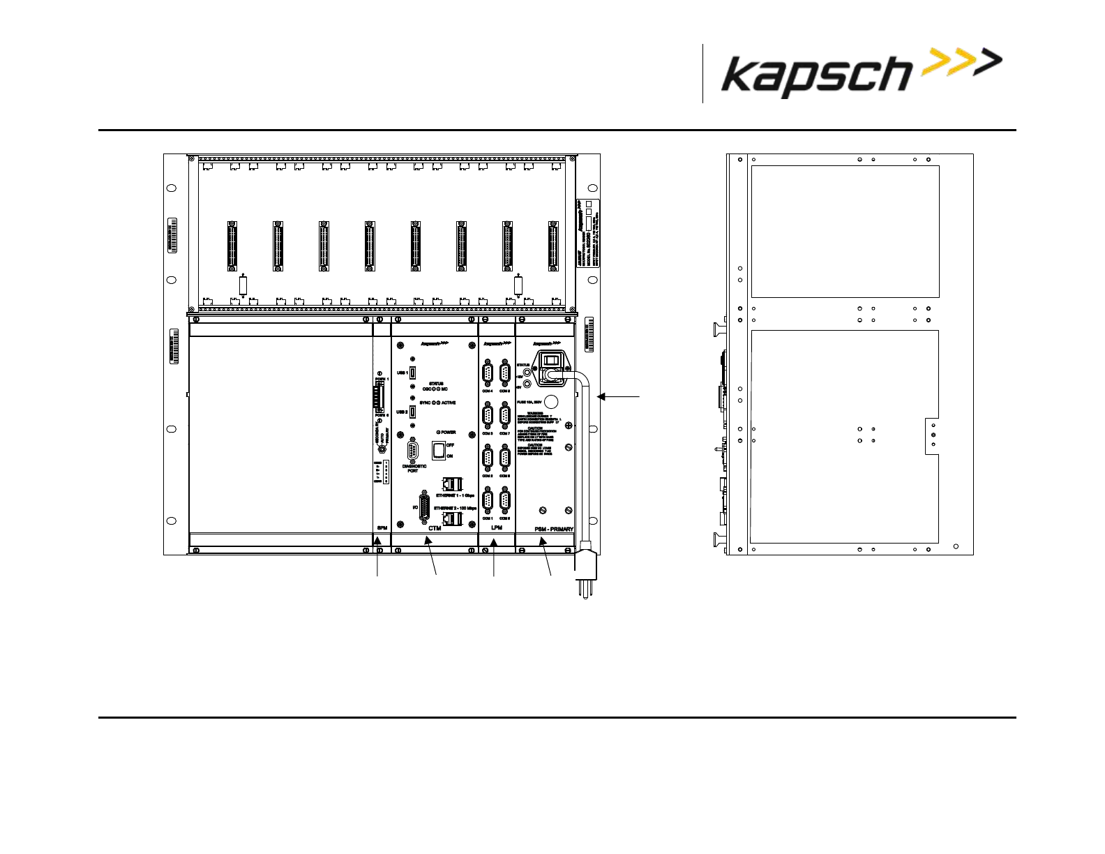
_
JANUS® Multi-Protocol Reader Ver. 2: Appendix
Confidential UM 360463-202: A12 (Draft) Page 290 of 291
© Kapsch TrafficCom Canada Inc. 2013
These drawings and specifications contain confidential and proprietary information and are the property of Kapsch TrafficCom Canada Inc. and are issued in strict confidence and will be kept confidential and used solely for the purpose
intended and for no other purpose and shall not be transmitted, reproduced, copied, and/or used as the basis for manufacture or sale of apparatus unless otherwise agreed to in writing by Kapsch TrafficCom Canada Inc.
FILE: MPR2_OPERATIONS_AND_MAINTENANCE-MANUAL_REV A12.DOCX 05/08/2014 11:24
Kapsch TrafficCom

_
JANUS® Multi-Protocol Reader Ver. 2: Appendix
Confidential UM 360463-202: A12 (Draft) Page 291 of 291
© Kapsch TrafficCom Canada Inc. 2013
These drawings and specifications contain confidential and proprietary information and are the property of Kapsch TrafficCom Canada Inc. and are issued in strict confidence and will be kept confidential and used solely for the purpose
intended and for no other purpose and shall not be transmitted, reproduced, copied, and/or used as the basis for manufacture or sale of apparatus unless otherwise agreed to in writing by Kapsch TrafficCom Canada Inc.
FILE: MPR2_OPERATIONS_AND_MAINTENANCE-MANUAL_REV A12.DOCX 05/08/2014 11:24
Kapsch TrafficCom