KONICA MINOLTA AERODRP5 AeroDR SYSTEM 2 User Manual Short Term Confidential 1
KONICA MINOLTA, Inc. AeroDR SYSTEM 2 Short Term Confidential 1
Contents
- 1. (Short-Term Confidential) User Manual_1
- 2. (Short-Term Confidential) User Manual_2
(Short-Term Confidential) User Manual_1
0197
Operation Manual
EN 01
A45YBD01EN01
20131220CT
DIRECT DIGITIZER AeroDR SYSTEM 2
Operation Manual
SYSTEM 2
DIRECT DIGITIZER

3
Contents
Chapter 3
General Operations 45
3.1 Startupandshutdown...............46
3.1.1 Startupsequenceofthisdevice. . . . . 46
3.1.2 Startupofthisdevice. . . . . . . . . . . . . 46
3.1.3 Shutdownsequenceofthisdevice. . 48
3.1.4 Shutdownofthisdevice. . . . . . . . . . . 49
3.2 OperationofAeroDRDetector. . . . . . . . . 51
3.2.1 Exposure......................51
3.2.2 AeroDRDetectororientation. . . . . . . 52
3.2.3 Precautionsforexposure. . . . . . . . . . 52
3.3 ChargingofAeroDRDetector. . . . . . . . . 56
3.3.1 ChargingwithAeroDR
BatteryCharger. . . . . . . . . . . . . . . . . 56
3.3.2 ChargingwithAeroDRBattery
Charger2......................57
3.3.3 Chargingwiththewiredcable. . . . . . 59
3.3.4 Chargingtimeguide. . . . . . . . . . . . . . 59
3.3.5 AeroDRDetectorchargingdisplay...59
3.4 RegistrationandselectionoftheAeroDR
Detector..........................60
3.4.1 RegistrationwithAeroDRBattery
Charger.......................60
3.4.2 RegistrationwithAeroDRBattery
Charger2......................60
3.4.3 Registrationwiththewiredcable. . . . 61
3.4.4 SelectionoftheAeroDRDetector. . . 61
3.4.5 ManualselectionoftheAeroDR
Detector.......................62
3.5 Calibration........................63
3.6 PositiontoafxAeroDRDetector
identicationlabel. . . . . . . . . . . . . . . . . . 64
Chapter 4
Status (LED) Display 65
4.1 LEDdisplayofrespectivedevices. . . . . . 66
4.1.1 AeroDRDetector. . . . . . . . . . . . . . . . 66
4.1.2 AeroDRInterfaceUnit. . . . . . . . . . . . 67
4.1.3 AeroDRInterfaceUnit2. . . . . . . . . . . 68
4.1.4 AeroDRGeneratorInterfaceUnit....69
4.1.5 AeroDRBatteryCharger. . . . . . . . . . 70
4.1.6 AeroDRBatteryCharger2. . . . . . . . . 71
4.1.7 AccessPoint . . . . . . . . . . . . . . . . . . . 72
Chapter 5
Troubleshooting 73
5.1 Supportowduringtrouble...........74
5.2 Variousproblemsandcountermeasures. . 76
5.2.1 AeroDRDetector. . . . . . . . . . . . . . . . 76
5.2.2 AeroDRInterfaceUnit. . . . . . . . . . . . 78
Introduction 5
Introduction..............................6
IndicationsforUse. . . . . . . . . . . . . . . . . . . . . . . 6
Summaryofusabilityspecications
(forIEC/EN60601-1-6,IEC/EN62366). . . . . . . 7
Disclaimer..............................7
Trademark.............................8
AeroDRSYSTEMnamecorrespondencetable. . 8
Termdescription.........................8
Structureofpages. . . . . . . . . . . . . . . . . . . . . . . 9
Chapter 1
Safety Precautions & Warnings
11
1.1 Symbolsrelatingtosafety . . . . . . . . . . . . 12
1.1.1 Safetyalertsymbol . . . . . . . . . . . . . . 12
1.1.2 Warningnotice(signalwords). . . . . . 12
1.1.3 Descriptionofgraphicsymbols. . . . . 12
1.2 Warninglabels. . . . . . . . . . . . . . . . . . . . . 13
1.2.1 AeroDRDetector. . . . . . . . . . . . . . . . 13
1.2.2 AeroDRBatteryCharger. . . . . . . . . . 14
1.2.3 AeroDRBatteryCharger2. . . . . . . . . 14
1.3 Safetyprecautions. . . . . . . . . . . . . . . . . . 15
1.3.1 Precautionsbeforeusage. . . . . . . . . 15
1.3.2 Precautionsforusage. . . . . . . . . . . . 15
1.3.3 Precautionsregarding
electromagneticwaves . . . . . . . . . . . 18
1.3.4 Precautionsregardingwireless
communication. . . . . . . . . . . . . . . . . . 23
1.3.5 Precautionsforinstalling,moving,
andstoring.....................25
1.3.6 Precautionsregardingmaintenance. . 26
1.3.7 Precautionsonservicelife. . . . . . . . . 27
1.3.8 Pediatricpatients’use;. . . . . . . . . . . . 27
1.4
R&TTEDECLARATIONofCONFORMITY
. . 28
Chapter 2
Product Overview 31
2.1 Overviewofthisdevice..............32
2.1.1 Functions......................32
2.1.2 Systemcongurationand
connectionexamples . . . . . . . . . . . . 32
2.2 Componentnamesandfunctions. . . . . . 36
2.2.1 AeroDRDetector. . . . . . . . . . . . . . . . 36
2.2.2 AeroDRInterfaceUnit. . . . . . . . . . . . 37
2.2.3 AeroDRInterfaceUnit2. . . . . . . . . . . 38
2.2.4 AeroDRGeneratorInterfaceUnit....39
2.2.5 AeroDRBatteryCharger. . . . . . . . . . 40
2.2.6 AeroDRBatteryCharger2. . . . . . . . . 41
2.2.7 AccessPoint . . . . . . . . . . . . . . . . . . . 42
2.2.8 AeroDRI/FCable................43
2.2.9 AeroDRUFCable. . . . . . . . . . . . . . . 43

Contents
4
5.2.3 AeroDRInterfaceUnit2. . . . . . . . . . . 78
5.2.4 AeroDRBatteryCharger. . . . . . . . . . 79
5.2.5 AeroDRBatteryCharger2. . . . . . . . . 79
5.2.6 AccessPoint . . . . . . . . . . . . . . . . . . . 79
5.2.7 Imageprocessingcontroller/Images. . 80
Chapter 6
Maintenance 81
6.1 Maintenanceandinspectionitems . . . . . 82
6.1.1 Maintenanceschedule. . . . . . . . . . . . 82
6.1.2 Cleaning.......................82
6.1.3 DisinfectionoftheAeroDRDetector. . 84
6.1.4 Consumables. . . . . . . . . . . . . . . . . . . 84
Chapter 7
Specications 85
7.1 Specications . . . . . . . . . . . . . . . . . . . . . 86
7.1.1 AeroDRDetector. . . . . . . . . . . . . . . . 86
7.1.2 AeroDRInterfaceUnit. . . . . . . . . . . . 89
7.1.3 AeroDRInterfaceUnit2. . . . . . . . . . . 89
7.1.4 AeroDRGeneratorInterfaceUnit....90
7.1.5 AeroDRBatteryCharger. . . . . . . . . . 90
7.1.6 AeroDRBatteryCharger2. . . . . . . . . 91
7.1.7 AccessPoint . . . . . . . . . . . . . . . . . . . 91
7.1.8 AeroDRI/FCable................92
7.1.9 AeroDRUFCable. . . . . . . . . . . . . . . 92
7.1.10 AeroDRXGCable. . . . . . . . . . . . . . . 92
7.1.11 AeroDRS-SRMCable. . . . . . . . . . . . 93
7.1.12 GeneralAeroDRSYSTEM. . . . . . . . . 93

5
Introduction
6
Introduction
DigitalradiographyAeroDRSYSTEM(hereafterreferredtoasthisdevice)performsX-rayimagingofthehumanbody
usinganX-rayplanardetectorthatoutputsadigitalsignal,whichistheninputintoanimageprocessingdevice,andthe
imageacquiredwithadigitalimageacquisitiondeviceisthentransmittedtoalingsystem,printer,andimagedisplay
deviceasdiagnosticimagedata.
• DiagnosticX-rayimagedataofthisdevicedoesnotprovidemammographicimages.
• Thisdeviceisalsousedforcarryingoutexposuresonchildren.
Thereare5typesofX-rayplanardetectorsforthisdevice:AeroDR1417HQ(AeroDRP-11),AeroDR1417S(AeroDR
P-12),AeroDR1717HQ(AeroDRP-21),AeroDR1012HQ(AeroDRP-31)andAeroDRII1417HQ(AeroDRP-51),
andconnectionismadebyeitherwirelessorwiredconnection.
TheDIRECTDIGITIZERCS-7orImagePilot(hereafterreferredtoastheimageprocessingcontroller),whichcontrols
thereceiving,processing,andoutputofimagedataofthisdevice,isrequiredforoperation.Fortheoperationoftheim-
ageprocessingcontroller,refertothe“OperationManual”oftheimageprocessingcontroller.
Thisoperationmanualprovidesinstructionsonthebasicfunctionsforoperationofthisdevice.Thoseoperatingthis
deviceforthersttimeshouldreadthismanualbeforehand.
Also,storethismanualclosetothisdeviceafterreadingitthrough,soitcanbeusedasaguidetoallowoptimum
operatingconditions.
*If the pages of the operation manual are smudged and illegible, replace it with a new one (There is a fee
for this service)
* The illustrations in this manual use the AeroDRII 1417HQ (AeroDR P-51) and AeroDR Battery Charger as
the example
Indications for Use
TheAeroDRSYSTEMisindicatedforuseingeneratingradiographicimagesofhumananatomy.Itisintendedtore-
placeradiographiclm/screensystemsingeneral-purposediagnosticprocedures.
<OnlyforUSA>
TheAeroDRSYSTEMwithP31isnotindicatedforuseinmammography,uoroscopy,tomographyandangiography
applications.
CAUTION
Federal law restricts this device to sale by or on the order of a phisitian

7
Introduction
Summary of usability specications (for IEC/EN 60601-1-6, IEC/EN 62366)
1) Medicalpurposes
• Provisionandreadingofdiseaseandinjurydiagnosticimages.
2) Patientgroups
• Nopatientpopulationexistswhousesorisincontactwiththedevice.
• PatientpopulationfortheX-rayimagesreadisnotspecied.
3) Partsofbodyororganizationstowhichthedeviceismountedorthatinteractwiththedevice.
• AeroDRDetectorcontactsthebodysurfaceofapatient.
• AeroDRInterfaceUnit/AeroDRInterfaceUnit2contactsthebodysurfaceofanoperator.
4) Operatingprinciple
• AeroDRDetectorformsthestillimagesaccordingtotheX-rayenergypassingthroughthehumanandanimal
body;afterdigitizingtheexposedimage,itistransmittedtotheconsole(theimageprocessingcontroller)with
wiredorwirelesscommunicationbywayofAeroDRInterfaceUnit/AeroDRInterfaceUnit2.
• AeroDRInterfaceUnit/AeroDRInterfaceUnit2suppliesthepowertoanyofAeroDRDetector,AeroDRGenera-
torInterfaceUnit,andAccessPoint(radiocommunicationdevice).
• AeroDRGeneratorInterfaceUnitorAeroDRInterfaceUnit2interfaceswithanX-raydevice.
• AccessPoint(radiocommunicationdevice)performsawirelesscommunicationwithAeroDRDetector.
• Theconsole(theimageprocessingcontroller)processestheimagedataintothediagnosticimage,andthen
storesandoutputstheimagesaddedwiththepatientinformation.
•
TheAeroDRBatteryCharger/AeroDRBatteryCharger2chargestheAeroDRDetector.Itregisterstheusingcas-
settewiththeexposureroom.
5) Signicantphysicalcharacteristics
• Referto"7.1Specications".
6) Signicantperformancecharacteristics
• Referto"2.1Overviewofthisdevice".
7) Userofthisdevice
• Nospecialtrainingisrequiredtousethisdevice.Theintendedusersofthisdeviceareasfollows.
Aprofessionalingoodhealthwithspecialistknowledge/qualicationswhohasfullyunderstoodthecontentof
thisdocument.(Suchasadoctororradiologicaltechnologist)
Disclaimer
(1)ThismanualmaynotbereproducedinwholeorinpartwithoutthepermissionofKonicaMinolta,Inc.
(2)Thecontentsofthismanualmaybesubjecttochangewithoutpriornotice.
(3)KonicaMinolta,Inc.isnotresponsibleforanyclaimsmadeformalfunctionordamagecausedbyinstallation,
relocation,modification,maintenance,andrepairmadebyanyoneexceptKonicaMinoltaandcontractors
designatedbyKonicaMinolta.
(4)KonicaMinolta,Inc.isnotresponsibleforanyclaimsmadeformalfunctionordamagetoKonicaMinoltaproducts,
causedbythird-partyproductsnotinstalledbyKonicaMinolta.
(5)KonicaMinolta,Inc.isnotresponsibleforanyclaimsmadeformalfunctionordamagecausedbymaintenanceor
repairusingmaintenancepartsotherthanthosespeciedbyKonicaMinolta.
(6)KonicaMinolta,Inc.isnotresponsibleforanyclaimsmadeformalfunctionordamagecausedbynotobserving
theprecautionsandoperationmethodsdescribedintheoperationmanual.
(7)KonicaMinolta,Inc.isnotresponsibleforanyclaimsmadeformalfunctionordamagecausedbytheenvironment
thatisnotsuitablefortheinstallationrequirementssuchaspowersourceandinstallationenvironmentdescribed
intheInstallationRequirementoroperationmanual.
(8)KonicaMinolta,Inc.isnotresponsibleforanyclaimsformalfunctionordamagecausedbyactsofnaturesuchas
res,earthquakes,oods,orlightningstrikes.
(9)KonicaMinolta,Inc.isnotresponsibleforanyclaimsformalfunctionordamagecausedbyusingthisdevicefor
anypurposeotherthanthatspeciedforthisdevice.
(10)
Diagnosticandtreatmentactionisperformedundertheresponsibilityofthephysician(s).KonicaMinolta,Inc.is
notresponsibleforanydiagnostic/treatmentconditionsordiagnostic/treatmentresults.

8
Introduction
Trademark
Companynamesandproductnamesinthismanualaretrademarksorregisteredtrademarksoftheirrespective
owners.
Pleasenotethat©,®and™marksareomittedhereafter.
Copyright©2014KonicaMinolta,Inc.AllRightsReserved.
AeroDR SYSTEM name correspondence table
Product name (Operation
Manual name) Model name (nameplate name)
AeroDRDetector
AeroDRP-11
AeroDRP-12
AeroDRP-21
AeroDRP-31
AeroDRP-51
AeroDRInterfaceUnit AeroDRB-1
AeroDRInterfaceUnit2 AeroDRInterfaceUnit2
AeroDRGeneratorInterface
Unit AeroDRX-1
AeroDRBatteryCharger AeroDRD-1
AeroDRBatteryCharger2 AeroDRBatteryCharger2
Term description
Themeaningsoftermsusedinthisoperationmanualareasfollows:
Terms Explanation
AeroDRDetector CollectivetermindicatingAeroDR1417HQ,AeroDR1417S,AeroDR1717HQ,AeroDR
1012HQandAeroDRII1417HQ.
Imageprocessingcontroller Theimageprocessingworkstation(CS-7orImagePilot)isreferredtoastheimageprocessing
controller.
Calibration ProcessingforcalibratingthecharacteristicsoftheAeroDRDetectorforeachpixel.
PoE AnabbreviationforPoweroverEthernet.ProvidespowerusinganEthernetcable.
Wiredcable CollectivetermindicatingAeroDRI/FCableandAeroDRUFCable.
AeroSync ThisisamodeinwhichexposureisperformedwithoutbeingsynchronizedwiththeX-ray
device.
9
Introduction
Structure of pages
46
3.1 Startupandshutdown
3.1.2 Startupofthisdevice
The startup methods of this device are as follows.
OAeroDRInterfaceUnit,AeroDRGenerator
InterfaceUnitandAccessPoint
• The startup methods of the AeroDR Interface
Unit, AeroDR Generator Interface Unit and Ac-
cess Point are as follows.
1 TurnthepowerswitchoftheAeroDRIn-
terfaceUniton,andconrmthattheLED
(green)lights.
Power switchLED (green)
2 WhenthepowerswitchoftheAeroDR
InterfaceUnitisturnedon,powerisalso
suppliedtotheAeroDRGeneratorInter-
faceUnit,andtheLED(green)willash.
LED (green)
HINT •••••••••••••••••••••••••••••••••••••
• In Aero Sync mode, the AeroDR Generator Interface
Unit is not used.
•••••••••••••••••••••••••••••••••••••••••••••••••••••
Normally, this device is used with the power on.
When not used for more than 1 day, operate the start-
up/shutdown as follows.
Reference
•••••••••••••••••••••••••••••••••••••
•
Refer to the "Operation Manual" of the image processing
controller regarding on/off for the image processing controller.
•••••••••••••••••••••••••••••••••••••••••••••••••••••
3.1.1 Startupsequenceofthis
device
The startup sequence of this device is as follows.
OWhenusingAeroDRInterfaceUnit
1AeroDR Interface Unit
AeroDR Generator
Interface Unit
Access Point
2
Image processing controller
3AeroDR Detector
4AeroDR Battery Charger/
AeroDR Battery Charger2
Conrm that the AeroDR Detector is ready for
use on the image processing controller.
OWhenusingAeroDRInterfaceUnit2
1AeroDR Interface Unit2
Access Point
2
Image processing controller
3AeroDR Detector
4AeroDR Battery Charger/
AeroDR Battery Charger2
Conrm that the AeroDR Detector is ready for
use on the image processing controller.
(1)
(4)
(2)
(3)
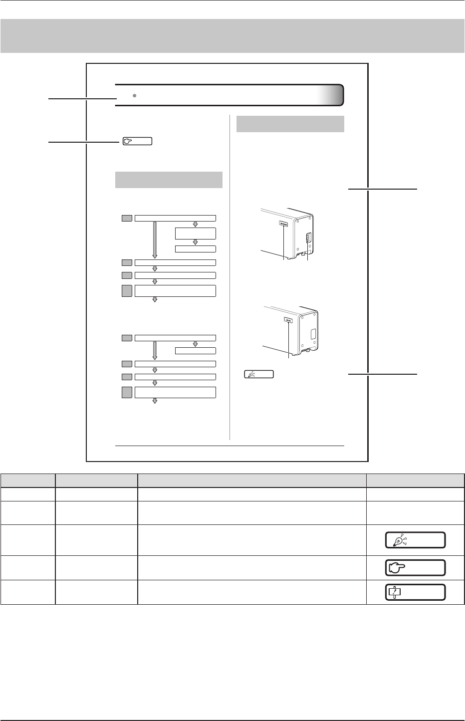
Number Item Description Icon
(1) Itemheading Describesthetitlesofdescribedcontent. -
(2) Operationprocedure Theoperatingprocedureisdescribedinsequentialnumerical
steps. -
(3) Hint Describesimportantinformation. HINT
(4) Reference Describesreferenceitems.Refertotheseasnecessary.
Reference
- Importantitems Describestheimportantitemsforoperation.Besuretoread
them.
IMPORTANT

10

11
Chapter 1
Safety Precautions & Warnings
Thischapterdescribesprecautionsandwarnings
toensuresafeuseofthisdevice.
12
111
Safety alert symbol
Thisisa"safetyalertsymbol".Thissymbolalertsyou
tomattersand/oroperationpotentiallyhazardousto
yourselfandotherpeople.Readthesemessagesand
followtheinstructionscarefully.
112 Warning notice (signal
words)
Signalwordsindicatethedegreeofpotentialhazards
intheuseoftheproduct.
Signalwordsincludethefollowingthreetypes,which
areusedaccordingtoriskofdamagecausedbydan-
gerandtheseverityofdamage.
DANGER
Indicatesanimminentlyhazardoussituationwhich,if
notavoided,willresultindeathorseriousinjury.
WARNING
Indicatesapotentiallyhazardoussituationwhich,ifnot
avoided,couldresultindeathorseriousinjury.
CAUTION
Indicatesapotentiallyhazardoussituationwhich,if
notavoided,couldresultinminorormoderateinjury.
Itmayalsobeusedtoindicatehazardoussituation
whereonlyphysicaldamageislikelytooccur.
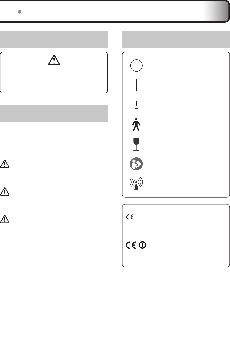
113 Description of graphic
symbols
Indicates the off position forthemain
powerswitchofthisdevice.
Indicatestheonpositionforthemain
powerswitchofthisdevice.
Indicatesthepositionwheretheground
isattached.
IndicatesaB-typeAppliedPartsmedical
device.
Indicatesthatfullcautionisrequired
whenhandlingthisdevice.
Indicatesthatitisnecessarytoreadthe
User'sManualbeforeuseoroperationof
thisdevice.
Indicates devices including radio fre-
quencytransmitters.
0197
ItmeansconformitywiththeMedicalDe-
vicesDirective93/42/EEC.
0197isNotiedBodynumber.
ItmeansconformitywiththeRadio
EquipmentandTelecommunications
TerminalEquipmentDirective1999/5/
EC.Andthealertsign(!)meansthatis
categorizedClass2radioequipment.
11 Symbols relating to safety
13
Chapter 1
12 Warning labels
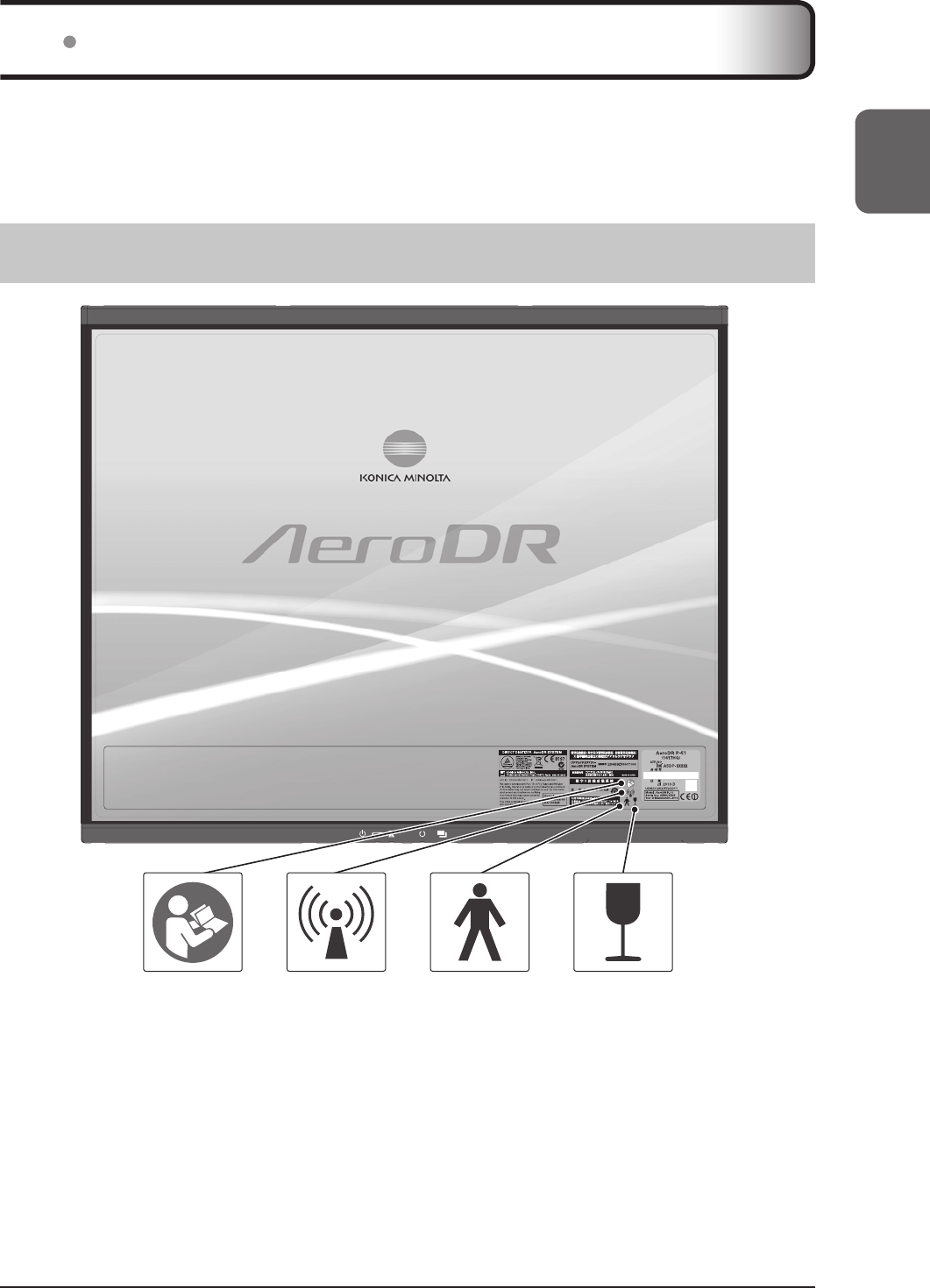
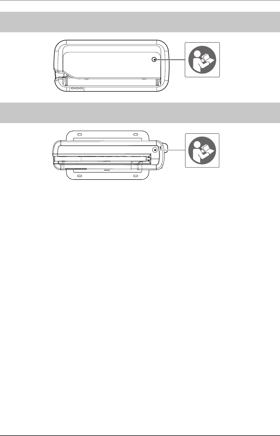
Variouswarninglabelsareattachedtothisdeviceonthelocationsshownbelow.Donotremovetheselabelsfromthisde-
vice.Warninglabelsaretheretomakesurethattheuserrecognizespotentialhazardswhenoperatingthisdevice.
* Ifawarninglabelistoodirtyordamagedtoread,contactKonicaMinoltatechnicalrepresentativestohaveanew
warninglabelattached,andredisplaybypartsreplacement.(Thereisafeeforthisservice.)
121 AeroDR Detector
14
1.2Warninglabels
122 AeroDR Battery Charger
123 AeroDR Battery Charger2
15
Chapter 1
132 Precautions for usage
WARNING
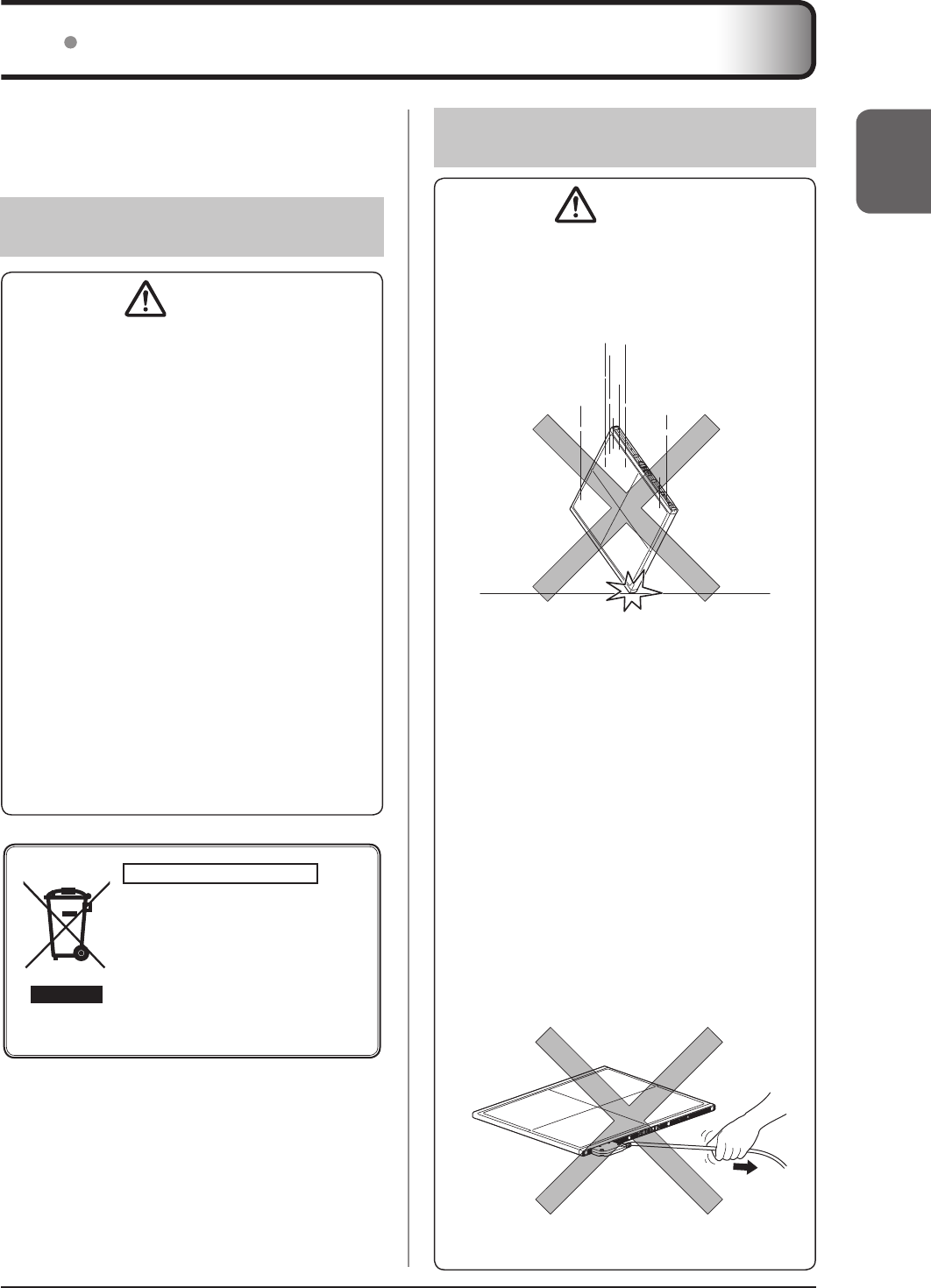
• TheAeroDRDetectorisaprecisioninstrument.Ifit
isdroppedorhitagainstanyobject,afailuremay
occurduetostrongimpactorexcessiveload.
• Takenoteofthefollowingwhenusingthisdevice:
–
DonotsubjecttheAeroDRDetectortostrong
shocksorexcessiveloadsbydroppingit,etc.
– Donotexceedthespeciedoverallloadrange
whenapplyingaloadtoanAeroDRDetector.
– Donotdisassembleormodifythisdevice.
– Donotconnectanydevicesthatwerenotpur-
chasedfromKonicaMinolta.
– Donotturnthepowerswitchofforpulloutthe
powercablewhilethesystemisoperating.
– BecarefulnottodroptheAeroDRDetector
onanypartofaperson'sbodybycatchingthe
AeroDRI/FCableorAeroDRUFCableonyour
feet.
– DonotleanonorputpressureontheAeroDR
BatteryChargerinstalledonawall.
• TheAeroDRI/FCableandAeroDRUFCableare
connectedtotheAeroDRDetectorusingmagnetic
force.WhenmovingtheAeroDRDetector,do
notholdontothecable,andalwaysholdonthe
AeroDRDetector.Also,donotgraspandpullthe
AeroDRDetectorforcefully.
13 Safety precautions
Readallsafetyprecautionsthoroughlybeforeusing
thisdevice.
Besuretoobservethesafetyprecautionsdescribedin
thissection.
131
Precautions before usage
CAUTION
• Theoperators(hospitalsandclinics)holdresponsi-
bilityfortheusageandmaintenanceofthisdevice.
Donotusethisdeviceunlessyouareaphysician
orcertiedpersonunderlaw.
• Thisdeviceexcludingtheimageprocessingcon-
trollerissuitableforuseinthepatientenvironment.
(PCusedfortheimageprocessingcontrollerisnot
suitableforuseinthepatientenvironment.)
• Confirmthatthisdeviceisoperatingnormallybe-
foreusing.
• Whenaproblemoccurswiththisdevice,turnthe
poweroff,attachanappropriatesign,suchas
"malfunction",onthisdevice,andcontactKonica
Minoltatechnicalrepresentatives.
• Thisdeviceisnotexplosion-proof,sodonotuse
anyammableorexplosivegasnearthisdevice.
• Forthebasicoperationofthecomputer,display
monitor,andoptionalpartsforthisdevice,referto
theiroperationmanuals.
• Pleasefollowtherulesandregulationsofyourrel-
evantauthoritiesinthedisposalofthisproduct,ac-
cessories,options,consumables,mediaandtheir
packingmaterials.
For EU member states only
Thissymbolmeans:Donotdisposeofthis
producttogetherwithyourhouseholdwaste!
Pleaserefertotheinformationofyourlocal
communityorcontactourdealersregarding
theproperhandlingofend-of-lifeelectricand
electronicequipments.
Recyclingofthisproductwillhelptoconserve
naturalresourcesandpreventpotentialnegative
consequencesfortheenvironmentandhuman
healthcausedbyinappropriatewastehandling.
1.3Safetyprecautions
16
WARNING
• Ifthereisanysmoke,odor,orabnormalsound,it
maycauseareifuseiscontinued,soimmediately
turnthepowerswitchoff,unplugthepowerplug
fromthewalloutlet,andcontactKonicaMinolta
technicalrepresentatives.
• Takenoteofthefollowingtoreducetheriskofre,
electricshock,orelectricalleakage:
– Usespeciedcablesforthepowercable,etc.
– Useawalloutletwiththecorrectratingasa
powersource.
– Connectthepowerplugtothewalloutletprop-
erlywithoutanyslack.
– Useagroundedpowersource.
– Ifyoudonotplantousethisdeviceforanex-
tendedperiodoftime,unplugthepowerplug.
– Thesuppliedpowercableisdedicatedforthis
device,sodonotuseitelsewhere.
– Avoidexposuretoliquidsuchaswater.
– Makesurethatforeignmaterial,suchaspieces
ofmetalorwire,doesnotgetinside.
– Donotallowanymetalorconductiveobjects
tocomeintocontactwiththespringconnector
oftheAeroDRI/FCable,AeroDRUFCableor
AeroDRBatteryCharger2.
– Donothandlethepowerplugwithwethands.
–
Donotletsoilordustaccumulateonthepower
plug,AeroDRI/FCable,AeroDR UFCableor
AeroDRBatteryCharger2.
– Donotuseextensioncords.
– Donotconnectmanyplugstoasingleelectrical
outlet.
– Donotdamagethepowercable,AeroDRI/F
Cable,orAeroDRUFCable.Also,donotuse
damagedcables.
– Donotblocktheventilationopenings.
• Ifthereisanyabnormalityinappearancesuchas
deformationofthehousingoracrack,stopusing
thedeviceimmediatelyandcontactKonicaMinolta
technicalrepresentatives.
CAUTION
• Takenoteofthefollowingwhenusingthisdevice:
– Donotusedevicesthatemitelectromagnetic
wavessuchashigh-frequencytherapyequip-
ment,mobilephones,orpocketpagers,closeto
thisdevice.
– Takenoteofthereceptionstatusforradiosand
TVsnearthisdevice,sinceinterferencemayoc-
curinthemwhenthisdeviceisinuse.
– Useunderthespecifiedenvironmentalcondi-
tions.Failuretodosomayresultindegradation
ofperformanceormalfunction.
– Limitcontinuoususeinahotandhumidenviron-
ment(35to37°C/95%orlower)ofanincubator
towithin25minutes.
– DonotinserttheAeroDR1012HQintotheAero-
DRBatteryChargerbecausethechargercannot
beusedforregistrationorchargingthebattery.
CAUTION
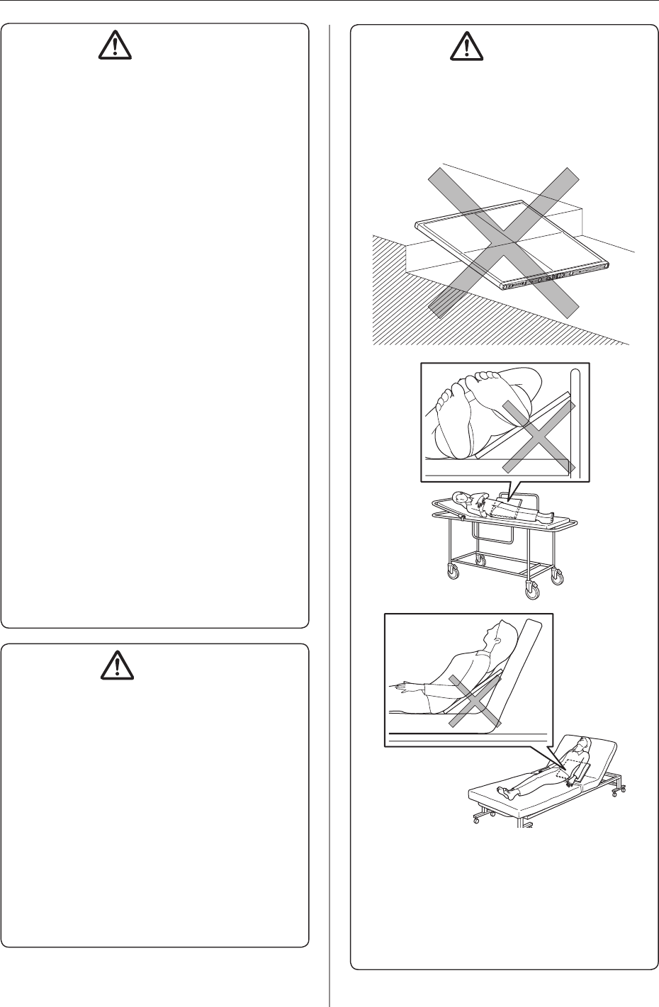
• TakethefollowingnoteswhenusingtheAeroDR
Detector:
– UsetheAeroDRDetectoronaatbase.Ifthe
AeroDRDetectorisplacedonaslopingsurface
andsubjectedtoaload,itsinternalsensormay
bedamaged.
– WhenlayingthepatientontotheAeroDRDetec-
torduringpositioning,dosoveryslowly.
– WhenplacingtheAeroDRDetectorunderthe
patientaspartoftheexposureprocess,insert
andpulloutthedetectorslowly.
– Usetherecommendedadapterwhenyouneed
toperformexposureonastretcheroraplace
whereloadistobeappliedlocally.
1.3Safetyprecautions
17
Chapter 1
CAUTION
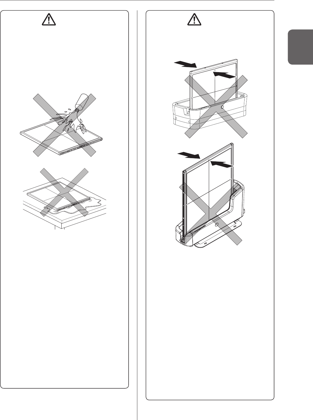
– TheAeroDRDetectorisnotwaterproof.Ifitis
exposedtoorimmersedinpatients'bodyuids,
chemicals,water,orotherliquids,suchliquids
mayentertheinstrumentthroughexteriorgaps,
causingafailure.Besuretouseavinylsheet
orothermaterialtocoverorwraptheAeroDR
DetectorwhenitispossiblethattheAeroDRDe-
tectormaybeexposedtopatients'bodyfluids,
chemicals,water,orotherliquids.
– NeverleaveAeroDRDetectorsinhotandhumid
environmentsforlongperiodsoftime.
– TheAeroDRDetectorhaswirelessantennaepo-
sitionedat2places.Donotblockthemwiththe
bodyormetalbecausethatwillinterferewith,dis-
connectorslowdownwirelesscommunication.
– PressingthepowerswitchcauseseachLED
(green,orange,blue)tolighttemporarilyor
ash.Afterthis,onlygreenbeginstoashina
slowcycle.Pleasecheckthelightingorashing
ofeachcoloronce.
– Thebatterycapacityisdesignedtoallowthelife
periodcalculatedbasedonthestandardusage
oftheAeroDRDetector.Itcanbereplacedwith
anewbatteryforafeeifreplacementisneces-
saryafterthewarrantyperiodduetobattery
breakdownordecreaseincapacity.
– CheckthatthebuzzersoundswhentheAeroDR
DetectorisinsertedintotheAeroDRBattery
Charger/AeroDRBatteryCharger2.Also,check
thattheLEDisinthechargestatus.
– Becarefulnottogetyourhandcaughtwhen
settingtheAeroDRDetectorintotheAeroDR
BatteryCharger/AeroDRBatteryCharger2.
CAUTION
– IftheAeroDRDetectorisinsertedintotheAero-
DRBatteryCharger/AeroDRBatteryCharger2,
makesurethattheAeroDRBatteryCharger/
AeroDRBatteryCharger2willnottipoverdueto
anyshockappliedtotheAeroDRDetector.
– TheAeroDRDetectorisprecisionequipment,
andthereforeimpactorvibrationduringradiog-
raphyorimagetransfermayaffecttheimage
quality.BecarefulwhenhandlingtheAeroDR
Detectorduringandjustafterradiography.
–
NeverleaveAeroDRDetectorsaroundheatgenera-
torssuchaselectriccarpet.
–
DonotdamageordeformtheAeroDRDetector;
doingsomayhaveaneffectonexposedimages,
orleadtoinjury.
• WhenusingtheAeroDRI/FCableorAeroDRUF
Cable,observethefollowing:
– Removethecablebyholdingtheconnector
housing.
– Donotletthecablegetpinchedbydoorsanddo
notplaceheavyobjectsonit.
– Donotbendorpullthecableexcessively.
– Makesurethatthecableisproperlyconnected
totheAeroDRDetectorwithoutwobbling.
– Donotconnecttheconnectorhousingback-
wards.
• DonotsitonorputyourfeetontheAeroDRBat-
teryCharger/AeroDRBatteryCharger2.

1.3Safetyprecautions
18
CAUTION
• TakenoteofthefollowingiftheAeroDRDetector
isdamagedanduorescentmediumorleadisex-
posed:
– Immediatelystopusingthedevice,andcontact
KonicaMinoltatechnicalrepresentatives.
– Iftheuorescentmediumgetsinyoureyes,do
notrubandinsteadwashwithrunningwaterim-
mediately.
– Ifyouhaveswallowedanyofthefluorescent
mediumoriftheuorescentmediumhasgotten
intoyoureyes,administerrst-aidtreatmentim-
mediately,andconsultadoctor.
– Ifthemediumcomesintocontactwithyourskin
directly,washtheaffectedareathoroughlywith
water.
– Useandstoreinalocationinaccessibletochil-
dren.
• WhentheAeroDRDetectorisusedforexposure,
payattentiontothefollowingitems.
– Startexposureafterconrmingonthedisplayof
theimageprocessingcontrollerthatthemachine
isreadyforexposure.
– PerformexposureundertheX-rayimagingcon-
ditionsthathasbeenconrmedbyus.
– Usethespeciedgridtoperformexposure.
– Applythespecifiedoperationmethodstouse
thegrid.
– DonotlettheAeroDRDetectorvibrateorre-
ceiveshockuntilthepreviewimageisdisplayed.
• Precautionswhenperformingexposurein
AeroSyncmode.
– Conrmthattheimageprocessingcontrolleris
readyforexposurethroughitsdisplaybefore
performingexposure.
– Conrmthataconrmationissoundedfromthe
imageprocessingcontrollerafterthestartofex-
posure.
– DonotlettheAeroDRDetectorvibrateorre-
ceiveshockuntilthepreviewimageisdisplayed.
– ConrmthattheAeroDRDetector'sbatterylevel
isfullbeforeperformingexposure.
– Usethesystemundertheexposurecondition
conrmedpriortoexposure.
• Whensettingthemaximumexposuretimeto4.0,
6.7,10.3,besuretocontactKonicaMinoltatechni-
calrepresentatives.
133 Precautions regarding
electromagnetic waves
EMC Statement
Thisdevicehasbeentestedandfoundtocomplywith
thelimitsformedicaldevicesinIEC60601-1-2:2007.
Theselimitsaredesignedtoprovidereasonablepro-
tectionagainstharmfulinterferenceinatypicalmedi-
calinstallation.Thedevicegenerates,usesandcan
radiateradiofrequencyenergyand,ifnotinstalledand
usedinaccordancewiththeinstructions,maycause
harmfulinterferencetootherdevicesinits vicinity.
However,thereisnoguaranteethatinterferencewill
notoccurinaparticularinstallation.
Whetherthisdevicedoescauseharmfulinterference
tootherdevicescanbedeterminedbyturningthisde-
viceoffandon.Ifitcausesharmfulinterference,the
userisencouragedtotrytocorrecttheinterferenceby
1ormoreofthefollowingmeasures:
• Reorientorrelocatethereceivingdevice.
• Increasetheseparationbetweenthedevices.
• Connectthisdeviceintoawalloutletonacircuitdiffer-
entfromthattowhichtheotherdevicesareconnected.
• ContactKonicaMinoltatechnicalrepresentatives.

1.3Safetyprecautions
19
Chapter 1
Supplementary information regarding IEC 60601-
1-2: 2007
(1)Takeprecautionsagainstthisdeviceespeciallyre-
gardingEMC.Installandputintoserviceaccording
totheelectromagneticcompatibility(EMC)informa-
tionprovidedinthemanual(Table1-Table4).
(2) Donotusemobilephonesorpocketpagersinthevicin-
ityofthisdevice.Useofmobilephonesorpocketpag-
ersnearthisdevicecancauseerrorsinoperationdue
toelectromagneticwaveinterference,sosuchdevices
shouldbeturnedoffinthevicinityofthisdevice.
(3)Cablelist
• Powercable(3.048m/3-Wire/NoShielding)
• Ethernetcable(max100m/100BASE-TX)
• Ethernetcable(PoE)(30m/NoShielding)
• VariousAeroDRI/FCables
• VariousAeroDRUFCables
• AeroDRCollimatorCableSet
• VariousAeroDRXGCableSets
(4)Theuseofaccessories,transducersandcables
otherthanthosesoldbyKonicaMinolta,Inc.as
internalcomponents,mayresultinincreasedemis-
sionsordecreasedelectromagneticimmunityof
thisdevice.
(5)Donotusethisdeviceadjacenttoorstackedwith
otherdevices.Ifadjacentorstackeduseisneces-
sary,conrmnormaloperationintheconguration
inwhichthisdevicewillbeused.
(6)SpecicationsregardingRFtransmittersfrequency:
• Frequency:2412to2472MHz
5180to5320MHz,5500to5825MHz
• Modulation:2412to2472MHz:DSSS/CCK/OFDM
5180to5320MHz,5500to5825MHz:
OFDM
• Maximumeffectiveradiationpower:+10dBm
• Thisdevicemaybeinterferedwithbyotherdevic-
esthatconformtoCISPRemissionrequirements.

20
1.3Safetyprecautions
Table 1
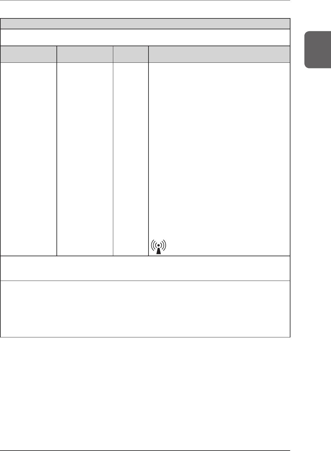
Guidelines and manufacture's declaration - electromagnetic emissions
Thisdeviceisintendedforuseintheelectromagneticenvironmentspeciedbelow.
Thecustomerortheuserofthisdeviceshouldassurethatitisusedinsuchanenvironment.
Emissions test Compliance Electromagnetic environment - guidelines
RFemissions
CISPR11 Group1
ThedeviceusesRFenergyonlyforitsinternalfunction.Therefore,itsRF
emissionsareverylowandarenotlikelytocauseanyinterferenceinnearby
electronicequipment.
RFemissions
CISPR11 ClassB
Thisdeviceissuitableforuseinallestablishmentsincludingthefollowing:
Domesticestablishmentsandthosedirectlyconnectedtothepubliclow-
voltagepowersupplynetworkthatsuppliesbuildingsfordomesticpurposes.
Harmonicemissions
IEC61000-3-2 ClassA
Voltageuctuations/
ickeremissions
IEC61000-3-3
Complies
Table 2
Guidelines and manufacturer's declaration - electromagnetic immunity
Thisdeviceisintendedforuseintheelectromagneticenvironmentspeciedbelow.
Thecustomerortheuserofthisdeviceshouldassurethatitisusedinsuchanenvironment.
Immunity test IEC 60601 test level Compliance level Electromagnetic environment -
guidelines
Electrostaticdischarge
(ESD)
IEC61000-4-2
±6kVcontact ±6kVcontact Floorsshouldbewood,concreteor
ceramictile.Ifoorsarecoveredwith
syntheticmaterial,therelativehumidity
shouldbeatleast30%.Mainspower
qualityshouldbethatofatypicalcom-
mercialorhospitalenvironment.
±8kVair ±8kVair
Electricalfasttransient/
burst
IEC61000-4-4
±2kVforpowersupply
lines
±2kVforpowersupply
lines
±1kVforinput/output
lines
±1kVforinput/output
lines
Surge
IEC61000-4-5
±1kVdifferentialmode ±1kVdifferentialmode Mainspowerqualityshouldbethatofa
typicalcommercialorhospitalenviron-
ment.
±2kVcommonmode ±2kVcommonmode
Voltagedips,short
interruptionsand
voltagevariationson
powersupplyinputlines
IEC61000-4-11
<5%UT(>95%dipinUT)
for0.5cycle
<5%UT(>95%dipinUT)
for0.5cycle Mainspowerqualityshouldbethatofa
typicalcommercialorhospitalenviron-
ment.Iftheuserofthedevicerequires
continuedoperationduringpowermains
interruptions,itisrecommendedthatthe
devicebepoweredfromanuninterrupted
powersupplyorabattery.
40%UT(60%dipinUT)
for5cycles
40%UT(60%dipinUT)
for5cycles
70%UT(30%dipinUT)
for25cycles
70%UT(30%dipinUT)
for25cycles
<5%UT(<95%dipinUT)
for5sec
<5%UT(<95%dipinUT)
for5sec
Powerfrequency
(50/60Hz)magnetic
eld
IEC61000-4-8
3A/m 3A/m
Powerfrequencymagneticeldsshould
beatlevelscharacteristicofatypicallo-
cationinatypicalcommercialorhospital
environment.
[NOTE]UTistheACmainsvoltagepriortoapplicationofthetestlevel.
21
Chapter 1
1.3Safetyprecautions
Table 3
Guidelines and manufacturer's declaration - electromagnetic immunity
Thisdeviceisintendedforuseintheelectromagneticenvironmentspeciedbelow.
Thecustomerortheuserofthisdeviceshouldassurethatitisusedinsuchanenvironment.
Immunity test IEC 60601
test level
Compliance
level Electromagnetic environment - guidelines
ConductedRF
IEC61000-4-6
RadiatedRF
IEC61000-4-3
3Vrms150kHz
to80MHz
3V/m80MHz
to2.5GHz
[3]V
[3]V/m
PortableandmobileRFcommunicationsequipment
shouldbeusednoclosertoanypartofthisdevice,includ-
ingcables,thantherecommendedseparationdistance
calculatedfromtheequationapplicabletothefrequencyof
thetransmitter.
Recommendedseparationdistance
d=[1.2]√P
d=[1.2]√P80MHzto800MHz
d=[2.3]√P800MHzto2.5GHz
wherePisthemaximumoutputpowerratingofthetrans-
mitterinwatts(W)accordingtothetransmittermanufac-
tureranddistherecommendedseparationdistancein
meters(m).
FieldstrengthsfromxedRFtransmitters,asdetermined
byanelectromagneticsitesurveya,shouldbelessthanthe
compliancelevelineachfrequencyrangeb.
Interferencemayoccurinthevicinityofequipmentmarked
withthefollowingsymbol:
[NOTE] At80MHzand800MHz,theseparationdistanceforthehigherfrequencyrangeapplies.
[NOTE] Theseguidelinesmaynotapplyinallsituations.Electromagneticpropagationisaffectedbyabsorptionand
reectionfromstructures,objectsandpeople.
a Fieldstrengthsfromxedtransmitters,suchasbasestationsforradio(cellular/cordless)telephonesandlandmobile
radios,amateurradio,AMandFMradiobroadcastandTVbroadcastcannotbepredictedtheoreticallywithaccuracy.
ToassesstheelectromagneticenvironmentduetoxedRFtransmitters,anelectromagneticsitesurveyshouldbe
considered.IfthemeasuredeldstrengthinthelocationinwhichthisdeviceisusedexceedstheapplicableRFcom-
pliancelevelabove,thisdeviceshouldbeobservedtoverifynormaloperation.Ifabnormalperformanceisobserved,
additionalmeasuresmaybenecessary,suchasreorientingorrelocatingthisdevice.
b Overthefrequencyrange150kHzto80MHz,eldstrengthshouldbelessthan[3]V/m.

22
1.3Safetyprecautions
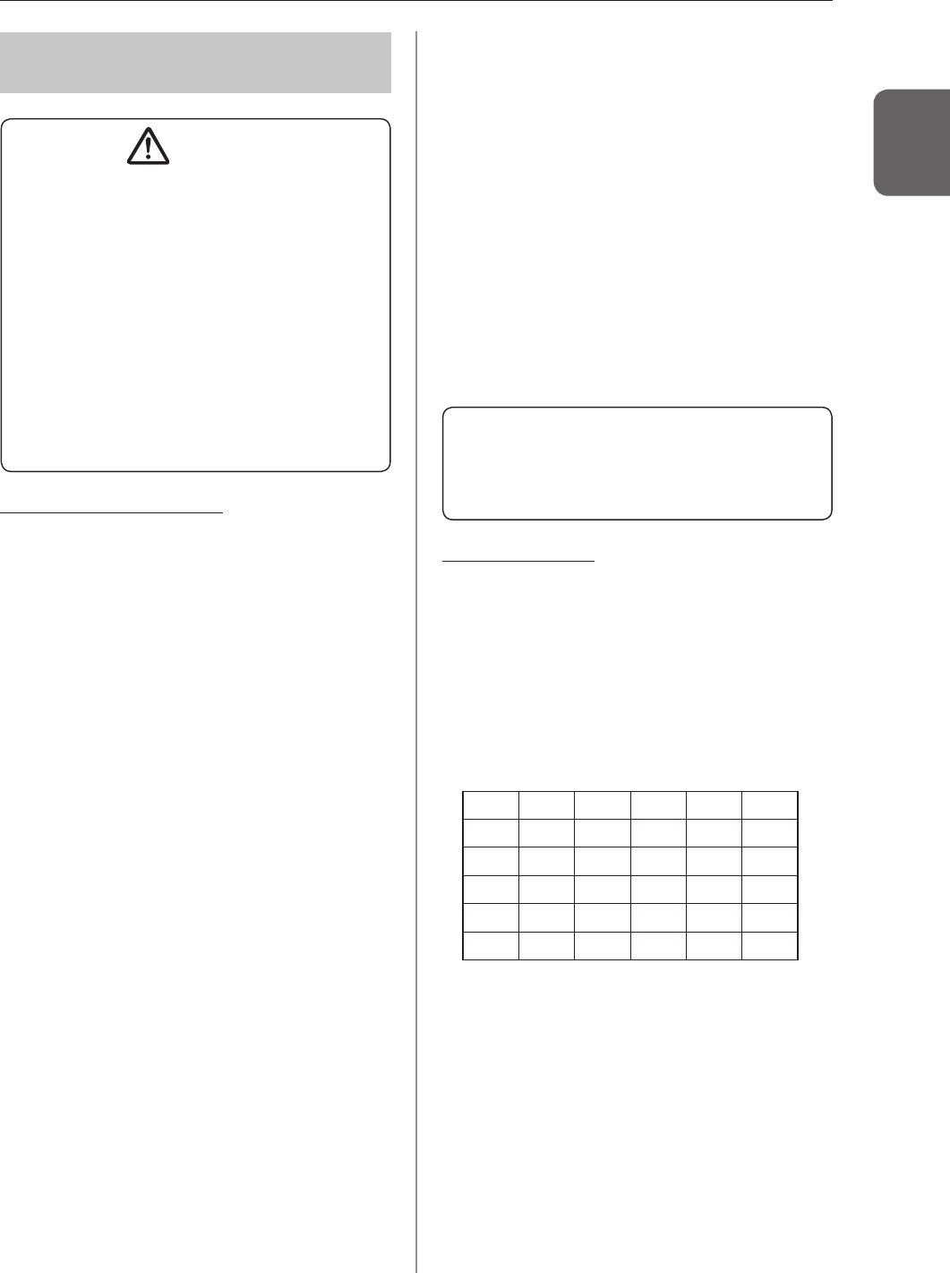
Table 4
Recommended separation distance between portable and mobile RF communications equipment and the device
ThisdeviceisintendedforuseinanelectromagneticenvironmentinwhichradiatedRFdisturbancesarecontrolled.The
customerortheuserofthisdevicecanhelppreventelectromagneticinterferencebymaintainingaminimumdistance
betweenportableandmobileRFcommunicationsequipment(transmitters)andthisdeviceasrecommendedbelow,
accordingtothemaximumoutputpowerofthecommunicationsequipment.
Rated maximum output
power of the transmitter
W
Separation distance according to frequency of transmitter
m
150 kHz to 80 MHz
d=[12] √P
80 MHz to 800 MHz
d=[12] √P
800 MHz to 25 GHz
d=[23] √P
0.01 0.12 0.12 0.23
0.1 0.38 0.38 0.73
1 1.2 1.2 2.3
10 3.8 3.8 8
100 12 12 23
Fortransmittersratedatamaximumoutputpowernotlistedabove,therecommendedseparationdistancedinmeters(m)
canbeestimatedusingtheequationapplicabletothefrequencyofthetransmitter,wherePisthemaximumoutputpower
ratingofthetransmitterinwatts(W)accordingtothetransmittermanufacturer.
[NOTE] At80MHzand800MHz,theseparationdistanceforthehigherfrequencyrangeapplies.
[NOTE] Theseguidelinesmaynotapplyinallsituations.Electromagneticpropagationisaffectedbyabsorptionand
reectionfromstructures,objectsandpeople.
1.3Safetyprecautions
23
Chapter 1
134 Precautions regarding
wireless communication
CAUTION
• Thisdeviceisequippedwithacommunicationfunc-
tionthatoperatesviawirelessLAN.Conformance
isrequiredwiththerelevantregulationsdenedby
thecountriesinwhichthisdeviceistobeused.
• Inappropriateusagemaycauseinterferenceinra-
diocommunication.Also,ifthisdeviceismodied,
approvalandwarrantyaccordingtotheradiolawof
theapplicablegovernmentwillbevoided.
• Itmayaffectaeronauticalsystems,sodonotuse
on-boardairplanes.
• Thisdevicemaybeaffectedbyotherwirelessde-
vices.Makesurethattheenvironmentisfreeof
wirelesscommunications.
• AeroDRDetectorhasbeenconfirmedtocomply
withtherelevantregulationsofthefollowingcoun-
tries:
United States & Canada
Federal Communications Commission
Statement / Canadian Department of Com-
munications
•AeroDR Detector complies with Part 15 of
FCC Rules and Industry Canada license-
exempt RSS standard(s).Operationis subject
to the following 2 conditions:(1) this device
may not cause interference, and (2) this
devicemustacceptanyinterference, including
interference that may cause undesired
operationofthisdevice.
•This transmitter must not be co-located or
operated in conjunction with any other an-
tennaortransmitter.
•5.15-5.35GHzband isrestrictedtoindoor
operationsonly.
•Theavailablescientificevidencedoesnot show
that any health problems are associated with
usinglowpowerwirelessdevices. There isno
proof, however, that these low power wireless
devices are absolutely safe. Low power
Wireless devices emit low levels of radio
frequencyenergy(RF)inthemicro-wave range
while being used. Whereas high levels of RF
canproducehealtheffects(by heating tissue),
exposureoflow-levelRFthat doesnot produce
heating effects causes no known adverse
health effects. Many studies of low-level RF
exposures have not found any biological
effects. Some studies have suggested that
some biological effects might occur, but such
findingshavenotbeencon-firmedbyadditional
research. AeroDR Detec-tor has been tested
and found to comply with FCC/IC radiation
exposure limits set forth for a controlled
equipmentandmeetstheFCC radio frequency
(RF)ExposureGuidelines and RSS-102ofthe
ICradiofrequency(RF) Exposurerules.
• CompliancewithFCCrequirement15.407(c):
Datatransmissionisalwaysinitiatedbysoft-
ware,whichisthepasseddownthroughthe
MAC,throughthedigitalandanalogbase-
band,andnallytotheRFchip.
Severalspecialpacketsareinitiatedbythe
MAC.Thesearetheonlywaysthedigital
basebandportionwillturnontheRFtransmit-
ter,whichitthenturnsoffattheendofthe
packet.Therefore,thetransmitterwillbeon
onlywhileoneoftheaforementionedpackets
isbeingtransmitted.Inotherwords,thisde-
viceautomaticallydiscontinuetransmission
incaseofeitherabsenceofinformationto
transmitoroperationalfailure.
• CompliancewithFCCrequirement15.407(g):
FrequencyTolerance:20ppm
FCC WARNING
Changesormodicationsnotexpresslyapproved
bythepartyresponsibleforcompliancecouldvoid
theuser'sauthoritytooperatetheequipment.
European Union
European Union Directives Conformance
Statement
AeroDRDetectorconformswiththeDeclara-
tionofConformity(DoC)toDirective1999/5/
EC(toR&TTEDirective).Thisdevicepur-
poselyconnectstoanaccesspointofa5GHz
network.
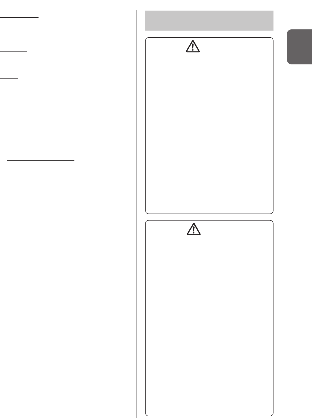
AeroDRDetectorisusedforthefollowingcoun-
triesindicatedbycountrycode(ISO31662-letter
code).
AT BE BG CY CZ DK
EE FI FR DE GR HU
IE IT LV LT LU MT
NL PL PT RO SK SI
ES SE GB IS LI NO
CH
•
High-power radars are allocated as primary
users (i.e. priority users) of the bands
5250-5350 MHz and 5650-5850 MHz and
that these radars could cause interference
and/or damage to LE-LAN devices.

1.3Safetyprecautions
24
Taiwan
Observe the following based on the regula-
tions stated in Article 10 of Administration
Measures for Low-power Radiation Electric
Machines
Article12
Asfortype-approvalqualiedlow-powerradio-
frequencygenerator,nocompany,rm,oruser
mayarbitrarilychangethefrequency,increase
thepoweroralterthefunctionorcharacteristics
oftheoriginaldesignwithoutpriorpermission.
Article14
Theuseoflow-powerradio-frequencyelectric
machinesshallnotaffectairflightsafetyor
disturblawfulcommunication.Ifdisturbanceis
found,theuseofsuchelectricmachinesshallbe
suspendedimmediatelyandsuchuseshallnot
beresumeduntilthedisturbanceiseliminated.
Lawfulcommunicationmentionedinthepre-
cedingparagraphreferstowirelesscommuni-
cationoperationinaccordancewiththeprovi-
sionsoftheTelecommunicationLaw.
Low-powerradio-frequencyelectricmachines
shalltoleratedisturbancefromlawfulcommu-
nicationorfromradio-waveradiationelectric
machineforindustrial,scienticormedicaluse.
China
1. Clearlyindicatethetechnicalindicatorsand
thescopeofusageintheaccompanyingdoc-
ument,andexplaintheusageofallcontrols,
adjustments,andswitches,etc.
Operatingfrequencyrange:5725-5850MHz
Transmitpower:≤500mWand≤27dBm
Equivalentisotropicradiatedpower(EIRP):
≤2Wand≤33dBm
Maximumradiationpowerdensity:
≤13dBm/MHzand≤19dBm/MHz(EIRP)
FrequencyTolerancelimit:20ppm
Transmitpoweratthebandedge(EIRP):
≤80dBm/Hz(≤5725MHzor≥5850MHz)
Spuriousemissions:
≤-36dBm/100kHz(30-1000MHz)
≤-40dBm/1MHz(2400-2483.5MHz)
≤-40dBm/1MHz(3400-3530MHz)
≤-33dBm/100kHz(5725-5850MHz)
(Note:Otherthan±2.5-timessupportedchannelbandwidth)
≤-30dBm/1MHz(Other1-40GHz)
2. Donotarbitrarilychangefrequencyorin-
creasetransmitpower(includingtheadded
radiofrequencyamplifier).Inaddition,do
notmountanantennawithoutpermission,or
changetoanothertransmissionantenna.
3.
Wheninuse,donotcauseharmfulinterferencein
otherlegalwirelesscommunicationservices.Ifyou
findinterferencetobeoccurring,discontinueuse
immediately.Aftertakingmeasurestoeliminatein-
terference,youmaycontinueusingthedevice.
4.
Ifyouuselowpowerradioequipment,youmust
acceptinterferencefromvariouswirelessser-
vicesorradiationinterferencefromindustrial,
scienticandmedicalapplicationequipment.
5. Donotusenearaplaneoranairport.
1.3Safetyprecautions
25
Chapter 1
South Korea
Becausethiswirelessequipmentmaybeaf-
fectedbyradiointerference,itcannotprovide
servicesrelatedwithlifesafety.
Thailand
AeroDRDetectorconformstoNTCtechnical
requirement.
Brazil
Thisequipmentoperatessecondarily,thatis,it
doesn'tbenefitfromprotectionagainstharm-
fulinterference,evenfromstationsofthesame
type,andcannotcauseinterferencetosystems
thatoperateprimarily.
AeroDRDetectorhasbeenapprovedbyANA-
TELincompliancewiththeproceduresregu-
latedbyResolution242/2000andcomplies
withtheapplicabletechnicalrequirements.
Formoreinformation,pleasevisit:
http://wwwanatelgovbr
Mexico
Thisequipmentoperatesonasecondaryba-
sis;consequently,youmustacceptharmfulin-
terferencesfromequipmentofthesametype,
andcannotcauseinterferencestosystems
operatingonaprimarybasis.
135 Precautions for install-
ing, moving, and storing
WARNING
• Takenoteofthefollowingwhenmovingthisdevice
notincludingtheAeroDRDetector:
– Donotsubjecttoshocksorvibration.
– Donotstartmovinguntilthepoweristurnedoff,
andoperationhasstoppedcompletely.
– Donotmovewiththepowercableoranyother
cableconnected.
• WheninstallingtheAeroDRBatteryCharger/AeroDR
BatteryCharger2onatabletop,observethefollowing:
– Installonabasethatcanwithstandmaximum
patientweightbecauseloadisinsertedwhen
settingtheAeroDRDetector.
– ThecontactareafortheAeroDRBatteryCharger/
AeroDRBatteryCharger2mustbelargerthanthe
areaoftheAeroDRBatteryChargersothatitwill
notfalldownwhentheAeroDRDetectorissetor
whenpeopletouchitbyaccident.
– Installonahorizontalandstablesurface.
– Donotuseabasethathasasurfacemadeof
slipperymaterialsuchasteon.
–
Connectpowercableandwiressothatnoonewilltrip.
–
InstallinaplaceeasytosettheAeroDRDetector.
–
Installsothattheventonthebacksideofthe
AeroDRBatteryCharger2isnotblocked.
CAUTION
• BecauseconnectionsoftheX-raydevicecanonlybe
madebyKonicaMinoltaoritsdesignatedcontractors,
contactKonicaMinoltaoritsdesignatedcontractors.
• ContactKonicaMinoltaordealersspecifiedby
KonicaMinoltatoinstallormovethisdevice.
• FortheX-raydevicesenabledtoconnect,contact
KonicaMinoltatechnicalrepresentatives.
• Sinceitisrequiredtomeetthespecificationpro-
videdbytheX-raydevicemanufacturertoconnect
withanX-raydevice,contactKonicaMinoltaor
dealersspeciedbyKonicaMinolta.
• Takenoteofthefollowingwheninstallingorstoring
thisdevice.
– Donotinstallorstoreinalocationwhereitmay
beadverselyaffectedbyatmosphericpressure,
temperature,humidity,ventilation,sunlight,dust,
salt-air,oraircontainingsulfur.
–
Donotinstallorstoreinalocationwhereitisnot
stable,ventilationisinsufficient,thedifference
inlight-darkisgreat,electromagneticwavesare
generated,orwheresubjecttovibrationorshock.
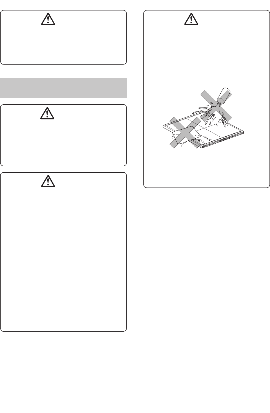
– Donotinstallorstoreinalocationwherechemi-
calagentsareusedorstored.
–
Donotinstallthisdevicefacinguporupsidedown.
– DonotinstalltheAeroDRInterfaceUnit,AeroDR
InterfaceUnit2andAeroDRGeneratorInterface
Unitstackedoneachother.
1.3Safetyprecautions
26
CAUTION
• ConnecttheAeroDRInterfaceUnit2/AeroDRGen-
eratorInterfaceUnittoanX-raydevicethatcon-
formstoIEC60601ortoanequivalentstandard.
• Donotuseaccesspointsotherthanthoseonthis
device.
136 Precautions regarding
maintenance
WARNING
• Performthemaintenanceandinspectionperiodi-
cally.Inadditiontotheuserperiodicalmaintenance
thatneedstobeperformed,periodicalmaintenance
byaserviceengineerisalsorequired.
• Iftherearestainssuchasbodyfluids,cleanand
disinfect.
CAUTION
• Basedonthewarranty,partsthatarenolongerun-
derwarranty(1year)canbereplacedforafee.
• Turnoffthepoweranddisconnectthepowerplug
fromthewalloutletbeforecleaningormaintaining
thisdevice.
• Securelyconnectthepowercable,AeroDRI/F
Cable,andAeroDRUFCableaftercleaningand
maintenance.
• Cleanthedirtfrombetweentheprotectivecover
andtheexterior,andtheterminalusingacommer-
cialplasticbrush.Donotcleanwithsharporhard
objects.
• Takecareregardingthefollowingwhendisinfecting
theAeroDRDetector.
– Useethanolfordisinfection,isopropanolfor
disinfection,orcommercialchlorinebleach,or
0.5%hypochlorite(10-folddilutionofhousehold
bleach)whendisinfecting.However,bleachand
hypochloritearecorrosive,sowashthebleach
offwelltoavoidcorrosion.
CAUTION
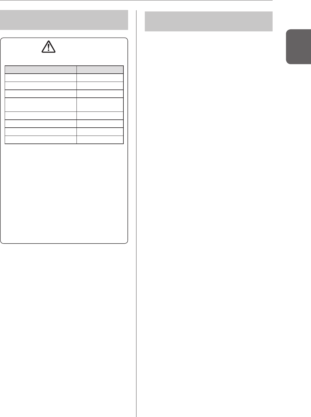
– Ifyoudirectlyapplyorspraydisinfectingsolution
ontheAeroDRDetector,thesolutionwillenter
theinstrumentthroughexteriorgaps,causinga
failure.Dampenalint-free,softclothwithdisin-
fectingsolution,anduseafterwringingitthor-
oughly.Donotapplydisinfectingsolutiononto
thewiredconnectionconnectorandLEDwhen
cleaning.
– Disinfectingsolutionisachemicalagent,sofol-
lowtheprecautionsofthemanufacturer.
• FullychargebatteryonceamontheveniftheAero-
DRDetectorhasnotbeenusedforalongtime.
1.3Safetyprecautions
27
Chapter 1
137 Precautions on service
life
CAUTION
Service life
Name Service life
AeroDRDetector 6years
AeroDRInterfaceUnit 6years
AeroDRInterfaceUnit2 6years
AeroDRGenerator
InterfaceUnit 6years
AeroDRBatteryCharger 6years
AeroDRBatteryCharger2 6years
AeroDRI/FCable 6years
AeroDRUFCable 6years
• Theaboveservicelifeisvalidonlyiftheproduct
hasbeenproperlyoperatedwhilefollowingthe
precautionsforuseandperformingthespecied
maintenance.(Byselfcertication<ourdata>)
• Theservicelifemaydifferdependingonusage
conditionsandenvironment.
• Somecomponentpartsofthisdevicearecom-
merciallyavailablepartsthathaveashortcycle
ofmodelchanges,therefore,itmightnotbe
possibletosupplyservicepartsevenwithinthe
servicelife.Inaddition,relatedcomponentparts
mayneedtobereplacedtomaintaincompatibil-
ityatthetimeofmodelchange.
138 Pediatric patients’ use;
AeroDRSystemwithP-31doesnothaveanX-ray
generatingfunction,anddoesnotcontrolX-raygen-
eratorunit.
AeroDRSystemwithP-31isusedconnectingwithX-
raygeneratorunitcurrentlyusedlegallyintheUnited
StatesofAmerica.
IncaseofusingAeroDRSystemwithP-31forpediat-
ricpatients,pleasemanageappropriatelyaspediatric
patientsreceivetheminimumnecessaryamountofX-
rayradiationforproducingdiagnosticqualityimages.
WhenusingAeroDRSystemwithP-31forthepediatric
patients,pleaseconnectonlywithanX-raygenerator
unitwhichhastheradiationmanagementfunctionfor
thepediatricpatients,andfollowtheinstructionofX-
raygeneratorunitforthepediatricpatients.
Forfurtherassistanceforthepediatricpopulationin-
cludesneonates,pleaserefertothefollowingHome
Pages.
TheImageGentlyBacktoBasicscampaignmaterials;
(http://www.pedrad.org/associations/5364/ig/?page=824)
FDA'sPediatricX-rayImagingwebpage;
(http://www.fda.gov/Radiation-EmittingProducts/RadiationEmitting
ProductsandProcedures/MedicalImaging/ucm298899.htm)
28
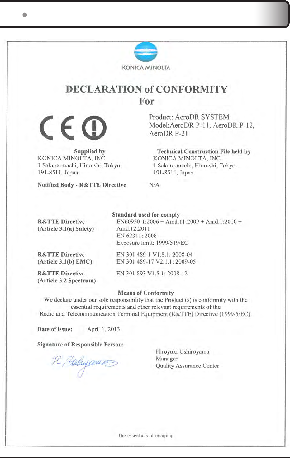
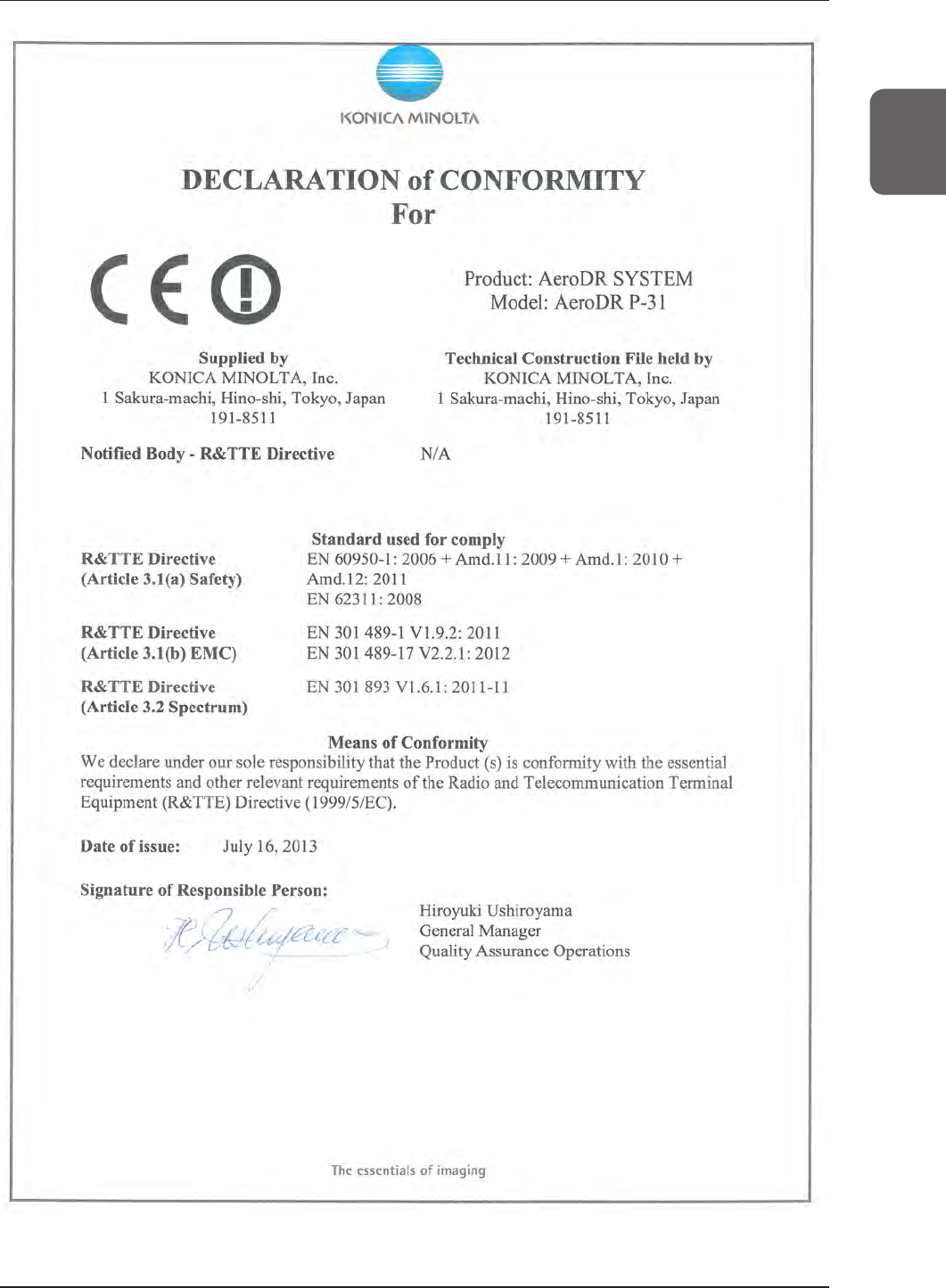
14 R&TTE DECLARATION of CONFORMITY
29
Chapter 1
1.4R&TTEDECLARATIONofCONFORMITY

30

31
Chapter 2
Product Overview
Thischapterdescribestheoverviewofthisdevice.

32
21 Overview of this device
Thissectiondescribesthefunctionsofthisdeviceaswellasasystemcongurationandconnectionexamplesusingthisdevice.
211 Functions
ThisdeviceconsistsofAeroDRDetector,AeroDRInterfaceUnit/AeroDRInterfaceUnit2,AeroDRGeneratorInterface
Unit,AeroDRBatteryCharger/AeroDRBatteryCharger2,AccessPoint,etc.WiththeAeroDRDetector,diagnostic
X-raydigitalimagedataisgeneratedbytheirradiationsignalandexposurefromanX-raydevice,andsenttotheim-
ageprocessingcontroller.
Furthermore,theAeroDRDetectorcanbeconnectedwith(orinsertedin)anAeroDRInterfaceUnit/AeroDRInterface
Unit2orAeroDRBatteryCharger/AeroDRBatteryCharger2orremovedfromthem.
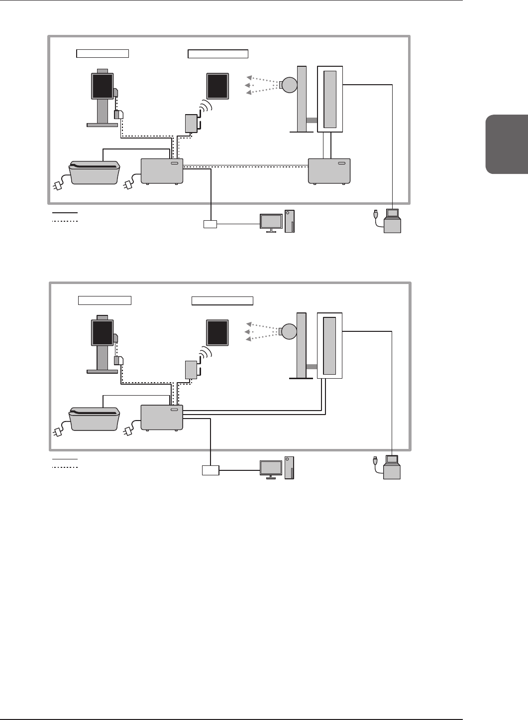
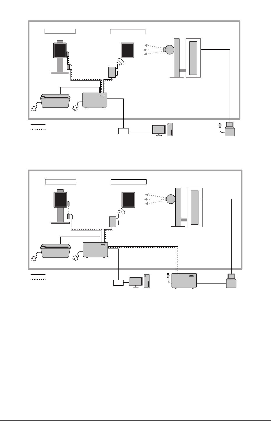
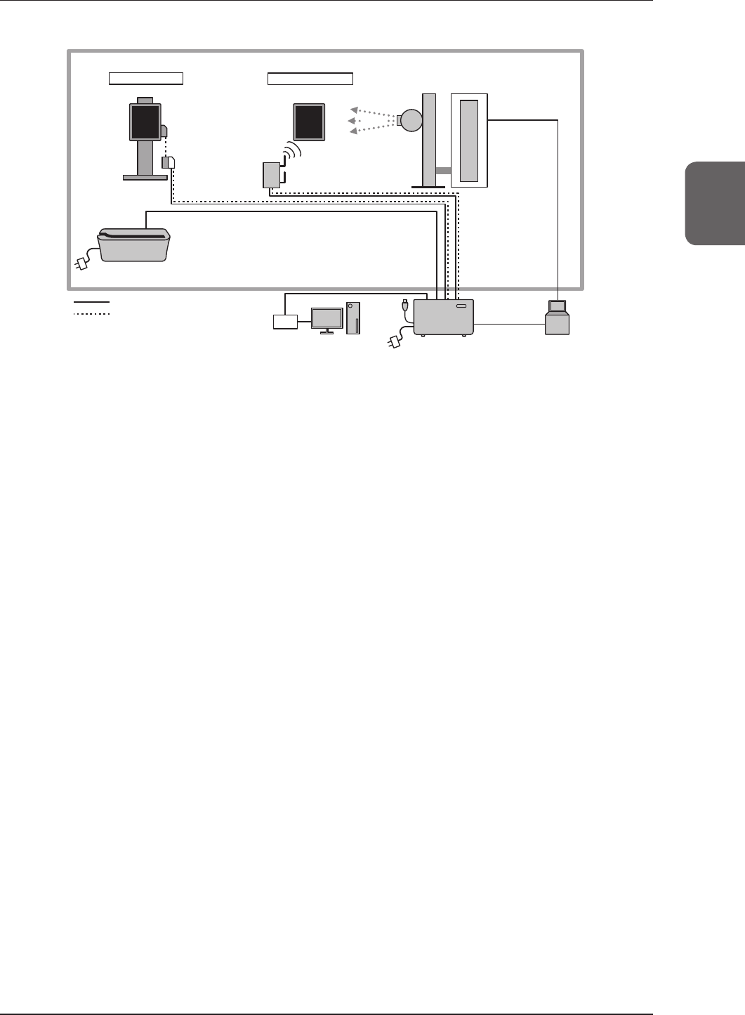
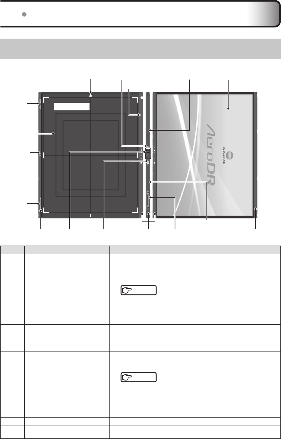
212 System conguration and connection examples
Thesystemcongurationandconnectionexamplesareasfollows.
Basic conguration example
Number Name Functions
(1) AeroDRDetector
• Thereare4typesofAeroDRDetectors:AeroDR1417HQ,AeroDR1417S,
AeroDR1717HQ,AeroDR1012HQandAeroDRII1417HQ.
• AeroDRDetectorisof
B-typeAppliedParts.
(2) AeroDRInterfaceUnit
• SuppliespowertotheAeroDRGeneratorInterfaceunitandtheAccessPoint,and
suppliespowertotheAeroDRDetectorandchargesthebatteryoftheAeroDR
DetectorwhenanAeroDRI/FCableorAeroDRUFCableisused.
• 4AeroDRDetectorscanbeconnectedviawirelessconnectionand2viawiredconnection.
• TheexpansionAeroDRInterfaceUnitisrequiredforconnectingthethirdand
fourthAeroDRDetectorsviawiredconnection.
(3)
AeroDRInterfaceUnit2
• SuppliespowertotheAccessPoint,andsuppliespowertotheAeroDRDetec-
torandchargesthebatteryoftheAeroDRDetectorwhenanAeroDRI/FCableor
AeroDRUFCableisused.
• 4AeroDRDetectorscanbeconnectedviawirelessconnectionand2viawiredcon-
nection.
• TheexpansionAeroDRInterfaceUnitisrequiredforconnectingthethirdandfourth
AeroDRDetectorsviawiredconnection.
• RelayssignalsbetweentheX-raydevice,theAeroDRDetector,andtheimage
processingcontroller.
(4)
AeroDRGeneratorInterfaceUnit
*
1
RelayssignalsbetweentheX-raydevice,theAeroDRDetector,andtheimage
processingcontroller.
(5) AeroDRBatteryCharger*1ChargestheAeroDRDetector.ItalsohastheregistrationfunctionfortheAeroDR
Detector.
• TheAeroDR1012HQcannotbechargedandregisteredusingtheAeroDRBatteryCharger.
(6) AeroDRBatteryCharger2*1ChargestheAeroDRDetector.ItalsohastheregistrationfunctionfortheAeroDR
Detector.
(7) AccessPoint
*1UsedforwirelessconnectionwiththeAeroDRDetector.*2
(8) AeroDRI/FCable
UsedforwiredconnectionwiththeAeroDRDetector.Alsousedforchargingand
registeringtheAeroDRDetector.
(9) AeroDRUFCable
*1UsedwhentheAeroDRDetectorissetinthewallstandortable.
(10) Imageprocessingcontroller Controlsthereception,management,andoutputofthisdevice'simagedata.
(11) AeroDRXGCable
*1
PerformssignalrelaybetweentheX-raydeviceandtheAeroDRGeneratorInterfaceUnit.
(12) AeroDRCollimatorCable
*1PerformsexposurefieldsignalrelaybetweentheX-raydeviceandtheAeroDR
GeneratorInterfaceUnit.
(13) AeroDRS-SRMCable
*1PerformssignalrelaybetweentheX-raydeviceoperationpanelandtheAeroDR
GeneratorInterfaceUnit.
(14) S-SRM
*1SynchronizesAeroDRGeneratorInterfaceUnitandX-raydevicesimply.Exposure
isperformedusingtheAeroDRGeneratorInterfaceUnit.
*1Optionalproduct.
*2TheAccessPointcanalsobeusedwithcommercialitems.
33
Chapter 2
2.1Overviewofthisdevice
Basic connection example 1
X-ray
(11) AeroDR
XG Cable
Tube
X-ray device
Wired connection
(1) AeroDR Detector
Exposure room Wireless connection
(1) AeroDR Detector
Wall stand
(9) AeroDR
UF Cable
(2) AeroDR Interface Unit
(8) AeroDR
I/F Cable (7) Access Point
(5) AeroDR
Battery Charger (4) AeroDR Generator
Interface Unit
Signal relay
Power supply
X-ray device
operation panel
(10) Image processing controller
Hub
(12) AeroDR
Collimator Cable
Basic connection example 2
X-ray
(11) AeroDR
XG Cable
Tube
X-ray device
(1) AeroDR Detector (1) AeroDR Detector
Wall stand (9) AeroDR
UF Cable
(3) AeroDR
Interface Unit2
(8) AeroDR
I/F Cable (7) Access Point
(5) AeroDR
Battery Charger
Signal relay
Power supply
X-ray device
operation panel
(10) Image processing controller
Hub
(12) AeroDR
Collimator Cable
Wired connection
Exposure room Wireless connection
34
2.1Overviewofthisdevice
Aero Sync connection example
Wired connection
(1) AeroDR Detector
Exposure room Wireless connection
(1) AeroDR Detector
Wall stand
(9) AeroDR
UF Cable
(8) AeroDR
I/F Cable
X-ray
(7) Access Point
X-ray device
operation panel
(10) Image processing controller
(2) AeroDR Interface Unit
Hub
Tube
X-ray device
(5) AeroDR
Battery Charger
Signal relay
Power supply
S-SRM connection example 1
(14) S-SRM
Hub
Wired connection
(1) AeroDR Detector
Exposure room Wireless connection
(1) AeroDR Detector
X-ray
(9) AeroDR
UF Cable
(2) AeroDR Interface Unit
(8) AeroDR
I/F Cable (7) Access Point
(5) AeroDR
Battery Charger
(4) AeroDR Generator
Interface Unit
Signal relay
Power supply
X-ray device
operation panel
Tube
X-ray device
(10) Image processing
controller
(13) AeroDR
S-SRM Cable
Wall stand
35
Chapter 2
2.1Overviewofthisdevice
S-SRM connection example 2
(14) S-SRM
Hub
Wired connection
(1) AeroDR Detector
Exposure room Wireless connection
(1) AeroDR Detector
X-ray
(9) AeroDR
UF Cable
(8) AeroDR
I/F Cable (7) Access Point
(5) AeroDR
Battery Charger
(3) AeroDR
Interface Unit2
Signal relay
Power supply
X-ray device
operation panel
Tube
X-ray device
(10) Image processing
controller
(13) AeroDR
S-SRM Cable
Wall stand
36
22 Component names and functions
221 AeroDR Detector
ThecomponentnamesandfunctionsoftheAeroDRDetectorareasfollows.
(8)Protectivecover
(2)Powerswitch (4)Shockwatch*
(7)Selection
switch
(9)Wiredconnection
connector
(4)Shockwatch
(5)Exterior
Exposureside
(8)Protectivecover
(6)LEDs
(3)Antenna
display
(5)Exterior
(8)Protective
cover
(4)Shock-
watch
(4)Shock-
watch
(3)Antennadisplay
(1)Triangularmark
Number Name Functions
(1) Triangularmark
IndicatesthedirectiontoplacetheAeroDRDetectorinduringexposure.
Whenexposinginportrait,placethetriangularmarkupward.
Whenexposinginlandscape,placethetriangularmarktotheleftorright.
(Leftandrightaresetduringinstallationaccordingtotheexposureenvironment.)
Reference
••••••••••••••••••••••••••••••••••••••••••••••••••
• FortheplacementoftheAeroDRDetectorduringexposure,referto
"3.2.2AeroDRDetectororientation".
••••••••••••••••••••••••••••••••••••••••••••••••••••••••••••••••••
(2) Powerswitch UsedtoturntheAeroDRDetectoron/off.
(3) Antennadisplay Displaystheplacewhereawirelessantennaisattached.
(4) Shockwatch
BecomesrediftheAeroDRDetectorissubjectedtoacertainamountofshock.
*AeroDR1012HQisequippedwithonlyoneShockwatch,whichisindicatedby"(4)
Shockwatch*"intheabovepicture.
(5) Exterior Protectstheinternalparts.
(6) LEDs
DisplaysthestatusoftheAeroDRDetector.
Reference
••••••••••••••••••••••••••••••••••••••••••••••••••
• ForthedisplaypatternsandstatusoftheLEDs,referto"4Status
(LED)Display".
••••••••••••••••••••••••••••••••••••••••••••••••••••••••••••••••••
(7) Selectionswitch NotiestheimageprocessingcontrollerthatthisAeroDRDetectorwillbeused
fortheexposure.
(8) Protectivecover Absorbsexternalshocks.
(9) Wiredconnectionconnector
ConnectstotheAeroDRBatteryCharger/AeroDRBatteryCharger2,AeroDRI/F
Cable,andAeroDRUFCable.
37
Chapter 2
2.2Componentnamesandfunctions
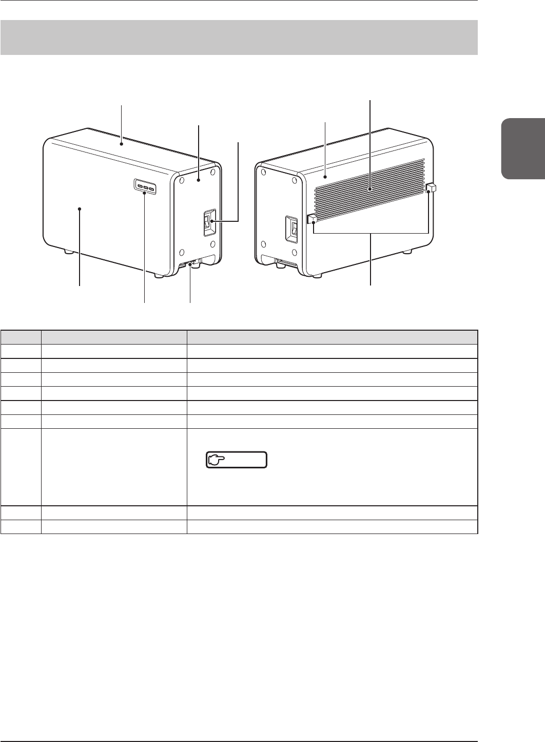
222 AeroDR Interface Unit
ThecomponentnamesandfunctionsoftheAeroDRInterfaceUnitareasfollows.
(9)Spacer
(5)Exhaustoutlet
(1)Topcover
(7)LEDs
(6)Frontcover
(2)Sidecover (4)Rearcover
(3)Powerswitch
(8)Cableoutlet
Number Name Functions
(1) Topcover Protectstheinternalparts.
(2) Sidecover Protectstheinternalparts.
(3) Powerswitch TurnstheAeroDRInterfaceUniton/off.
(4) Rearcover Protectstheinternalparts.
(5) Exhaustoutlet Exhaustsinternalheat.
(6) Frontcover Protectstheinternalparts.
(7) LEDs
DisplaysthestatusoftheAeroDRInterfaceUnit.
Reference
••••••••••••••••••••••••••••••••••••••••••••••••••
• ForthedisplaypatternsandstatusoftheLEDs,referto"4Status
(LED)Display".
••••••••••••••••••••••••••••••••••••••••••••••••••••••••••••••••••
(8) Cableoutlet Outletforvariouscables.
(9) Spacer Preventsexhaustoutletfrombeingblockedafterinstallation.
38
2.2Componentnamesandfunctions
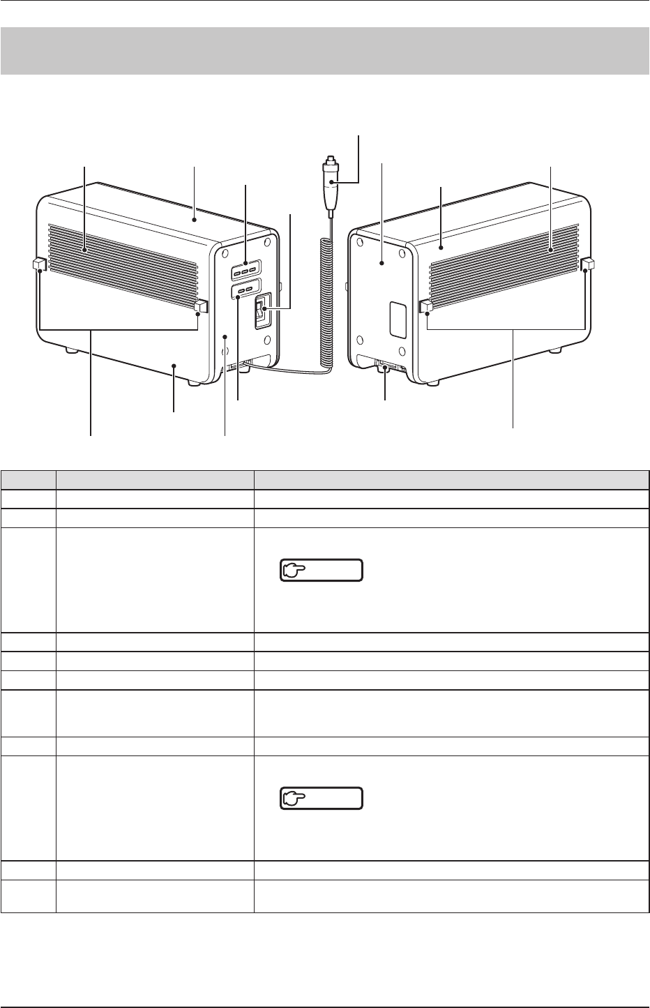
223 AeroDR Interface Unit2
ThecomponentnamesandfunctionsoftheAeroDRInterfaceUnit2areasfollows.
(1)Exhaustoutlet
(7)Spacer
(10)Cableoutlet
(6)Sidecover (9)Generator
InterfaceLEDs
(8)Frontcover
(7)Spacer
(1)Exhaustoutlet (2)Topcover
(4)Power
switch
(6)Sidecover
(5)Rearcover
(11)Handswitch
(3)Detector
Connection
LEDs
Number Name Functions
(1) Exhaustoutlet Exhaustsinternalheat.
(2) Topcover Protectstheinternalparts.
(3) DetectorConnectionLEDs
DisplaysthestatusoftheAeroDRInterfaceUnit2.
Reference
••••••••••••••••••••••••••••••••••••••••••••••••••
• ForthedisplaypatternsandstatusoftheLEDs,referto"4Status
(LED)Display".
••••••••••••••••••••••••••••••••••••••••••••••••••••••••••••••••••
(4) Powerswitch TurnstheAeroDRInterfaceUnit2on/off.
(5) Rearcover Protectstheinternalparts.
(6) Sidecover Protectstheinternalparts.
(7) Spacer
Preventsexhaustoutletfrombeingblockedafterinstallation.
*Nospacersmaybeprovidedonsomesidecoversthatwillnotcomeincon-
tactwithwalls.
(8) Frontcover Protectstheinternalparts.
(9) GeneratorInterfaceLEDs
DisplaysthestatusoftheAeroDRInterfaceUnit2.
Reference
••••••••••••••••••••••••••••••••••••••••••••••••••
• ForthedisplaypatternsandstatusoftheLEDs,referto"4Status
(LED)Display".
••••••••••••••••••••••••••••••••••••••••••••••••••••••••••••••••••
(10) Cableoutlet Outletforvariouscables.
(11) Handswitch WhenS-SRMconnectionisadopted,ahandswitchisinstalledintheAeroDR
InterfaceUnit2.
39
Chapter 2
2.2Componentnamesandfunctions
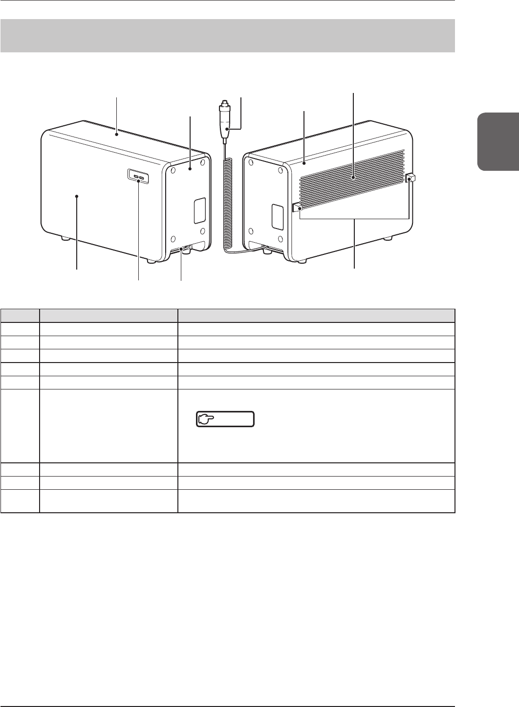
224 AeroDR Generator Interface Unit
ThecomponentnamesandfunctionsoftheAeroDRGeneratorInterfaceUnitareasfollows.
(8)Spacer
(4)Exhaustoutlet
(1)Topcover
(6)LEDs
(5)Frontcover
(2)Sidecover (3)Rearcover
(9)Handswitch
(7)Cableoutlet
Number Name Functions
(1) Topcover Protectstheinternalparts.
(2) Sidecover Protectstheinternalparts.
(3) Rearcover Protectstheinternalparts.
(4) Exhaustoutlet Exhaustsinternalheat.
(5) Frontcover Protectstheinternalparts.
(6) LEDs
DisplaysthestatusoftheAeroDRGeneratorInterfaceUnit.
Reference
••••••••••••••••••••••••••••••••••••••••••••••••••
• ForthedisplaypatternsandstatusoftheLEDs,referto"4Status
(LED)Display".
••••••••••••••••••••••••••••••••••••••••••••••••••••••••••••••••••
(7) Cableoutlet Outletforvariouscables.
(8) Spacer Preventsexhaustoutletfrombeingblockedafterinstallation.
(9) Handswitch WhenS-SRMconnectionisadopted,ahandswitchisinstalledintheAeroDR
GeneratorInterfaceUnit.
40
2.2Componentnamesandfunctions
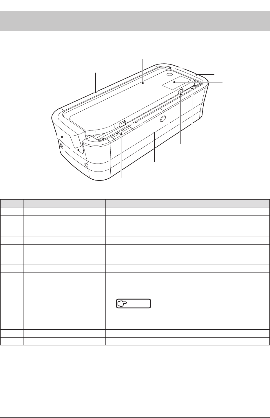
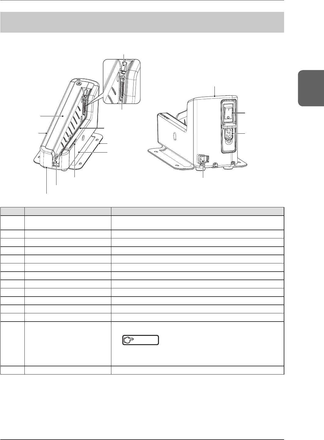
225 AeroDR Battery Charger
ThecomponentnamesandfunctionsoftheAeroDRBatteryChargerareasfollows.
(1)Rearcover
(8)LEDs
(9)Frontcover
(4)Sidecover
(5)Charge/
registrationlabel
(3)Topcover
(4)Sidecover
(6)AeroDRDetector
inserttable(front)
(10)Roller
(7)AeroDRDetector
inserttable(side)
(2)Slidecover
Number Name Functions
(1) Rearcover Protectstheinternalparts.
(2) Slidecover Protectstheinternalparts,andpreventsdustfromgettinginsidetheAeroDR
BatteryCharger.
(3) Topcover Protectstheinternalparts.
(4) Sidecover Protectstheinternalparts.
(5) Charge/registrationlabel
WhenanAeroDRBatteryChargerexclusivelyforchargeisused,alabelthat
distinguishestheAeroDRBatteryChargerexclusivelyforchargefroman
AeroDRBatteryChargerthatisusedforchargeandregistrationisafxed.
(6) AeroDRDetectorinserttable(front) GuideforinsertingtheAeroDRDetectorfromthefront.
(7) AeroDRDetectorinserttable(side) GuideforinsertingtheAeroDRDetectorfromtheside.
(8) LEDs
IndicatesthestatusbetweentheAeroDRDetectorandtheAeroDRBattery
Charger.
Reference
••••••••••••••••••••••••••••••••••••••••••••••••••
• ForthedisplaypatternsandstatusoftheLEDs,referto"4Status
(LED)Display".
••••••••••••••••••••••••••••••••••••••••••••••••••••••••••••••••••
(9) Frontcover Protectstheinternalparts.
(10) Roller PreventsexternalfrictionwhenyouinserttheAeroDRDetector.
41
Chapter 2
2.2Componentnamesandfunctions
226 AeroDR Battery Charger2
ThecomponentnamesandfunctionsoftheAeroDRBatteryCharger2areasfollows.
(4)Stand
(14)LANconnector
(3) Frontinsert
guide
(2)Wiredconnec-
tionconnector
(1)Connectorcover
(5)Front
cover
(9) Rearinsert
guide
(10)Rearcover
(11)Sidecover(left)
(12)AeroDRDetectorinserttable
(6) Sidecover(right)
(7) Power
switch
(8)Inlet
(13)LEDs
Number Name Functions
(1) Connectorcover Protectsthewiredconnectionconnectorandpreventsdustfromentering
insideit.
(2) Wiredconnectionconnector ConnectstothewiredconnectionconnectoroftheAeroDRDetector.
(3) Frontinsertguide Protectstheinternalparts.
(4) Stand ProtectstheAeroDRBatteryCharger2frombeingoverturned.
(5) Frontcover Protectstheinternalparts.
(6) Sidecover(right) Protectstheinternalparts.
(7) Powerswitch UsedtoturntheAeroDRBatteryCharger2on/off.
(8) Inlet ConnectstothepowercableofAeroDRBatteryCharger2.
(9) Rearinsertguide Protectstheinternalparts.
(10) Rearcover Protectstheinternalparts.
(11) Sidecover(left) Protectstheinternalparts.
(12) AeroDRDetectorinserttable AguideforinsertingtheAeroDRDetector.
(13) LEDs
DisplaysthestatusoftheAeroDRDetectorandAeroDRBatteryCharger2.
Reference
••••••••••••••••••••••••••••••••••••••••••••••••••
• ForthedisplaypatternsandstatusoftheLEDs,referto"4Status
(LED)Display".
••••••••••••••••••••••••••••••••••••••••••••••••••••••••••••••••••
(14) LANconnector ConnectstotheEthernetcable.
42
2.2Componentnamesandfunctions
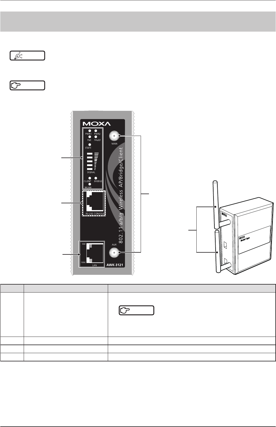
227 Access Point
ThecomponentnamesandfunctionsoftheAccessPointareasfollows.
HINT •••••••••••••••••••••••••••••••••••••••••••••••••••••••••••••••••••••••••••••••••••••••••••••••••••••
• Theillustrationsandexplanationmerelyshowsanexample.
•••••••••••••••••••••••••••••••••••••••••••••••••••••••••••••••••••••••••••••••••••••••••••••••••••••••••••••••••••••
Reference
•••••••••••••••••••••••••••••••••••••••••••••••••••••••••••••••••••••••••••••••••••••••••••••••••••••
• Fordetails,refertoeachdevice'smanual.
•••••••••••••••••••••••••••••••••••••••••••••••••••••••••••••••••••••••••••••••••••••••••••••••••••••••••••••••••••••
(2)10/100BASE-T(X)
RJ45port
(3)Antennaport
(4)Antenna
Cannotbeusedwiththis
device
(1)LEDs
Number Name Functions
(1) LEDs
DisplaysthestatusoftheAccessPoint.
Reference
••••••••••••••••••••••••••••••••••••••••••••••••••
• ForthedisplaypatternsandstatusoftheLEDs,referto"4Status
(LED)Display".
••••••••••••••••••••••••••••••••••••••••••••••••••••••••••••••••••
(2) 10/100BASE-T(X)RJ45port UsedforconnectiontotheAeroDRInterfaceUnit/AeroDRInterfaceUnit2.
(3) Antennaport Porttoattachantenna.
(4) Antenna Receiveswirelesssignal.
43
Chapter 2
2.2Componentnamesandfunctions
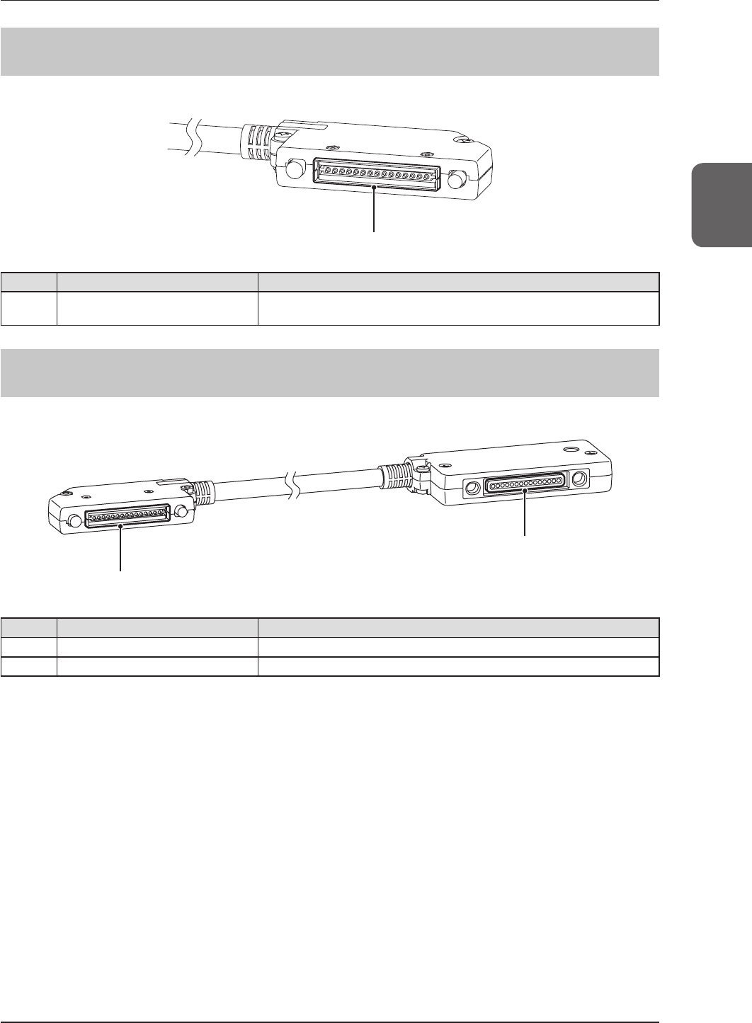
228 AeroDR I/F Cable
ThecomponentnameandfunctionoftheAeroDRI/FCableareasfollows.
(1)Springconnector
Number Name Functions
(1) Springconnector ConnectstothewiredconnectionconnectoroftheAeroDRDetectoror
AeroDRUFCable.
229 AeroDR UF Cable
ThecomponentnamesandfunctionsoftheAeroDRUFCableareasfollows.
(2)Wiredconnectionconnector
(1)Springconnector
Number Name Functions
(1) Springconnector ConnectstothewiredconnectionconnectoroftheAeroDRDetector.
(2) Wiredconnectionconnector ConnectstothespringconnectoroftheAeroDRI/FCable.

44