KROHNE FMCW24G74T Tank Level Probing Radar User Manual MA OPTIWAVE7400 24 en 151210 4003518001 R01
KROHNE Tank Level Probing Radar MA OPTIWAVE7400 24 en 151210 4003518001 R01
KROHNE >
Contents
- 1. Manual English
- 2. Manual French
Manual English
Radar (FMCW) Level Transmitter for agitated liquids in
high-precision applications
OPTIWAVE 7400-24 C
OPTIWAVE 7400-24 COPTIWAVE 7400-24 C
OPTIWAVE 7400-24 C Handbook
HandbookHandbook
Handbook
© KROHNE 12/2015 - 4003518001 - MA OPTIWAVE7400-24-R01-en

All rights reserved. It is prohibited to reproduce this documentation, or any part thereof, without
the prior written authorisation of KROHNE Messtechnik GmbH.
Subject to change without notice.
2
O
www.krohne.com 12/2015 - 4003518001 - MA OPTIWAVE7400-24-R01-en
Copyright 2015 by
KROHNE Messtechnik GmbH - Ludwig-Krohne-Str. 5 - 47058 Duisburg (Germany)
:
IMPRINT
:::::::::::::::::::::::::::::::::::::::

CONTENTS
3
www.krohne.com12/2015 - 4003518001 - MA OPTIWAVE7400-24-R01-en
OPTIWAVE 7400-24 C
1 Safety instructions 7
1.1 Software history ............................................................................................................... 7
1.2 Intended use ..................................................................................................................... 7
1.3 Certification ...................................................................................................................... 8
1.4 Electromagnetic compatibility ......................................................................................... 8
1.5 Radio approvals ................................................................................................................ 9
1.5.1 European Union (EU)............................................................................................................... 9
1.5.2 U.S.A. and Canada................................................................................................................. 12
1.6 Safety instructions from the manufacturer................................................................... 15
1.6.1 Copyright and data protection .............................................................................................. 15
1.6.2 Disclaimer ............................................................................................................................. 15
1.6.3 Product liability and warranty .............................................................................................. 16
1.6.4 Information concerning the documentation......................................................................... 16
1.6.5 Warnings and symbols used................................................................................................. 17
1.7 Safety instructions for the operator............................................................................... 17
2 Device description 18
2.1 Scope of delivery............................................................................................................. 18
2.2 Device description .......................................................................................................... 19
2.3 Visual Check ................................................................................................................... 20
2.4 Nameplates .................................................................................................................... 21
2.4.1 Nameplate (examples).......................................................................................................... 21
3 Installation 23
3.1 General notes on installation ......................................................................................... 23
3.2 Storage ........................................................................................................................... 23
3.3 Transport ........................................................................................................................ 24
3.4 Pre-installation requirements ....................................................................................... 24
3.5 Pressure and temperature ranges ................................................................................ 25
3.6 Recommended mounting position ................................................................................. 26
3.6.1 General data.......................................................................................................................... 26
3.6.2 Tanks with conical bottoms .................................................................................................. 27
3.7 Mounting restrictions ..................................................................................................... 28
3.7.1 General data.......................................................................................................................... 28
3.7.2 Obstacles in the tank ............................................................................................................ 28
3.7.3 Devices with Metallic Horn antenna..................................................................................... 29
3.7.4 Process connections............................................................................................................. 30
3.7.5 Standpipes (stilling wells and bypass chambers) ................................................................ 31
3.8 How to attach antenna extensions ................................................................................. 35
3.9 How to turn or remove the signal converter.................................................................. 36
3.10 How to assemble the remote version .......................................................................... 37
3.11 Weather protection....................................................................................................... 39
3.11.1 How to attach the weather protection to the device........................................................... 39
3.11.2 How to open the weather protection .................................................................................. 40
4 Electrical connections 41

CONTENTS
4
www.krohne.com 12/2015 - 4003518001 - MA OPTIWAVE7400-24-R01-en
OPTIWAVE 7400-24 C
4.1 Safety instructions.......................................................................................................... 41
4.2 Electrical installation: 2-wire, loop-powered ................................................................ 41
4.2.1 Compact version ................................................................................................................... 41
4.2.2 Remote version ..................................................................................................................... 42
4.3 Remote device data ........................................................................................................ 43
4.3.1 Requirements for signal cables supplied by the customer ................................................. 43
4.3.2 How to prepare a signal cable supplied by the customer.................................................... 44
4.3.3 How to connect the signal cable to the device ..................................................................... 45
4.4 Electrical connection for current output ....................................................................... 48
4.4.1 Non-Ex devices ..................................................................................................................... 48
4.4.2 Devices for hazardous locations........................................................................................... 48
4.5 Protection category ........................................................................................................48
4.6 Networks ........................................................................................................................ 49
4.6.1 General information.............................................................................................................. 49
4.6.2 Point-to-point connection..................................................................................................... 49
4.6.3 Multi-drop networks ............................................................................................................. 50
4.6.4 Fieldbus networks................................................................................................................. 50
5 Start-up 52
5.1 How to start the device................................................................................................... 52
5.1.1 Start-up checklist ................................................................................................................. 52
5.1.2 How to start the device ......................................................................................................... 52
5.2 Operating concept ..........................................................................................................52
5.3 Digital display screen .....................................................................................................53
5.3.1 Local display screen layout .................................................................................................. 53
5.3.2 Functions of keypad buttons................................................................................................. 54
5.4 Remote communication with PACTware™ .................................................................... 54
5.5 Remote communication with the AMS™ Device Manager............................................. 55
6 Operation 56
6.1 User modes .................................................................................................................... 56
6.2 Normal mode.................................................................................................................. 57
6.3 Configuration mode........................................................................................................ 58
6.3.1 General notes........................................................................................................................ 58
6.3.2 How to get access to the commissioning menu................................................................... 58
6.3.3 Keypad functions................................................................................................................... 59
6.3.4 Menu overview ...................................................................................................................... 62
6.3.5 Function description ............................................................................................................. 63
6.4 Further information on device configuration................................................................. 70
6.4.1 Quick Setup (Commissioning)............................................................................................... 70
6.4.2 Test........................................................................................................................................ 72
6.4.3 Protection of the device settings .......................................................................................... 73
6.4.4 HART
®
network configuration.............................................................................................. 73
6.4.5 Distance measurement ........................................................................................................ 74
6.4.6 Level measurement .............................................................................................................. 75
6.4.7 How to configure the device to measure volume or mass................................................... 76
6.4.8 How to make a filter to remove radar signal interference .................................................. 77
6.4.9 How to measure correctly in tanks with curved or conical bottoms ................................... 78
6.5 Status and error messages............................................................................................ 79
6.5.1 Device status (markers)........................................................................................................ 79

CONTENTS
5
www.krohne.com12/2015 - 4003518001 - MA OPTIWAVE7400-24-R01-en
OPTIWAVE 7400-24 C
6.5.2 Error handling....................................................................................................................... 80
7 Service 84
7.1 Periodic maintenance..................................................................................................... 84
7.2 How to clean the top surface of the device .................................................................... 84
7.3 How to clean horn antennas under process conditions ................................................ 84
7.4 How to replace device components ............................................................................... 84
7.4.1 Service warranty ................................................................................................................... 84
7.4.2 Replacement of the OPTIWAVE 7300 signal converter with the OPTIWAVE 7400 signal con-
verter............................................................................................................................................... 85
7.5 Spare parts availability...................................................................................................87
7.6 Availability of services .................................................................................................... 87
7.7 Returning the device to the manufacturer..................................................................... 88
7.7.1 General information.............................................................................................................. 88
7.7.2 Form (for copying) to accompany a returned device............................................................ 89
7.8 Disposal .......................................................................................................................... 89
8 Technical data 90
8.1 Measuring principle........................................................................................................90
8.2 Technical data................................................................................................................. 91
8.3 Minimum power supply voltage ..................................................................................... 99
8.4 Antenna selection......................................................................................................... 100
8.5 Guidelines for maximum operating pressure.............................................................. 101
8.6 Dimensions and weights .............................................................................................. 103
9 Description of HART interface 115
9.1 General description ...................................................................................................... 115
9.2 Software history ...........................................................................................................115
9.3 Connection variants...................................................................................................... 116
9.3.1 Point-to-Point connection - analogue / digital mode......................................................... 116
9.3.2 Multi-Drop connection (2-wire connection) ....................................................................... 116
9.4 HART® device variables............................................................................................... 116
9.5 Field Communicator 475 (FC 475)................................................................................ 116
9.5.1 Installation .......................................................................................................................... 116
9.5.2 Operation............................................................................................................................. 117
9.6 Asset Management Solutions (AMS)............................................................................ 117
9.6.1 Installation .......................................................................................................................... 117
9.6.2 Operation............................................................................................................................. 117
9.6.3 Parameter for the basic configuration ............................................................................... 117
9.7 Field Device Tool / Device Type Manager (FDT / DTM)................................................ 118
9.7.1 Installation .......................................................................................................................... 118
9.7.2 Operation............................................................................................................................. 118
9.8 HART® menu tree for Basic-DD .................................................................................. 118
9.8.1 Overview Basic-DD menu tree (positions in menu tree).................................................... 118
9.8.2 Basic-DD menu tree (details for settings).......................................................................... 118
9.9 HART® menu tree for AMS .......................................................................................... 119
9.9.1 Overview AMS menu tree (positions in menu tree)............................................................ 120

CONTENTS
6
www.krohne.com 12/2015 - 4003518001 - MA OPTIWAVE7400-24-R01-en
OPTIWAVE 7400-24 C
9.9.2 AMS menu tree (details for settings).................................................................................. 120
10 Appendix 122
10.1 Order code .................................................................................................................. 122
10.2 Spare parts ................................................................................................................. 130
10.3 Accessories................................................................................................................. 134
10.4 Glossary ...................................................................................................................... 135
11 Notes 138
SAFETY INSTRUCTIONS
1
7
OPTIWAVE 7400-24 C
www.krohne.com12/2015 - 4003518001 - MA OPTIWAVE7400-24-R01-en
1.1 Software history
"Firmware revision" agrees with NAMUR NE 53. It is a series of numbers used to record the
revision status of embedded software (firmware) in electronic equipment assemblies. It gives
data on the type of changes made and the effect that changes have on compatibility.
Data about software revisions is shown in menu 1.1.0 IDENT. For more data, refer to
Function
description
on page 63. If it is not possible to refer to the device menu, record the serial number
of the device (given on the device nameplate) and speak to the supplier.
1.2 Intended use
This radar level transmitter measures distance, level, mass, volume and reflectivity of liquids,
pastes and slurries.
It can be installed on tanks, reactors and open channels.
Release date Printed circuit
assembly
Firmware
revision
Hardware
revision
Changes and
compatibility
Documentation
YYYY-MM-DD Converter 1.00.0x 400xxxxx01 -HB OPTIWAVE
7400-24 R01
Sensor 1.00.0x 400xxxxx01
HMI (LCD display
option) 1.00.0x 400xxxxx01
CAUTION!
Responsibility for the use of the measuring devices with regard to suitability, intended use and
corrosion resistance of the used materials against the measured fluid lies solely with the
operator.
INFORMATION!
The manufacturer is not liable for any damage resulting from improper use or use for other than
the intended purpose.

1
SAFETY INSTRUCTIONS
8
OPTIWAVE 7400-24 C
www.krohne.com 12/2015 - 4003518001 - MA OPTIWAVE7400-24-R01-en
1.3 Certification
In accordance with statutory requirements of the EC directives, the device described in
this document meets the following safety requirements:
•Electromagnetic Compatibility Directive
•The safety part of the Low-Voltage Directive
For more data, refer to the CE Declaration of Conformity for this device.
All devices meet the requirements of NAMUR Guidelines NE 21, NE 43, NE 53 and NE 107.
1.4 Electromagnetic compatibility
The device agrees with Electromagnetic Compatibility Directive.
You can install the device on tanks, open vessels or channels, but the type of antenna must agree
with the location of the device. For more data, refer to
Radio approvals
on page 9. This agrees
with Immunity and Emissions requirements for industrial environments.
DANGER!
For devices used in hazardous areas, additional safety notes apply; please refer to the Ex
documentation.
INFORMATION!
For SIL-approved devices; please refer to the safety manual.
SAFETY INSTRUCTIONS
1
9
OPTIWAVE 7400-24 C
www.krohne.com12/2015 - 4003518001 - MA OPTIWAVE7400-24-R01-en
1.5 Radio approvals
1.5.1 European Union (EU)
This level transmitter is approved to be used outside metallic tanks. If you use the device
outdoors, read the device nameplate to make sure that the device can be used for your
application. Only the antennas that follow are permitted for open-air applications:
•VF744xxxx5xxx...
•VF744xxxx6xxx...
•VF744xxxx7xxx...
INFORMATION!
LPR (Level Probing Radar)
LPR (Level Probing Radar)LPR (Level Probing Radar)
LPR (Level Probing Radar) equipment are devices for the measurement of level in the open air
or in a closed space (a metallic tank etc.). TLPR (Tank Llevel Probing Radar)
TLPR (Tank Llevel Probing Radar)TLPR (Tank Llevel Probing Radar)
TLPR (Tank Llevel Probing Radar) equipment are
devices for the measurement of level in a closed space only. You can use LPR devices for TLPR
applications. The LPR and TLPR devices meet the requirements of the R&TTE (Radio Equipment
and Telecommunications Terminal Equipment) Directive for use in the member countries of the
EU.
For more data about the order code, refer to Order code on page 122
.
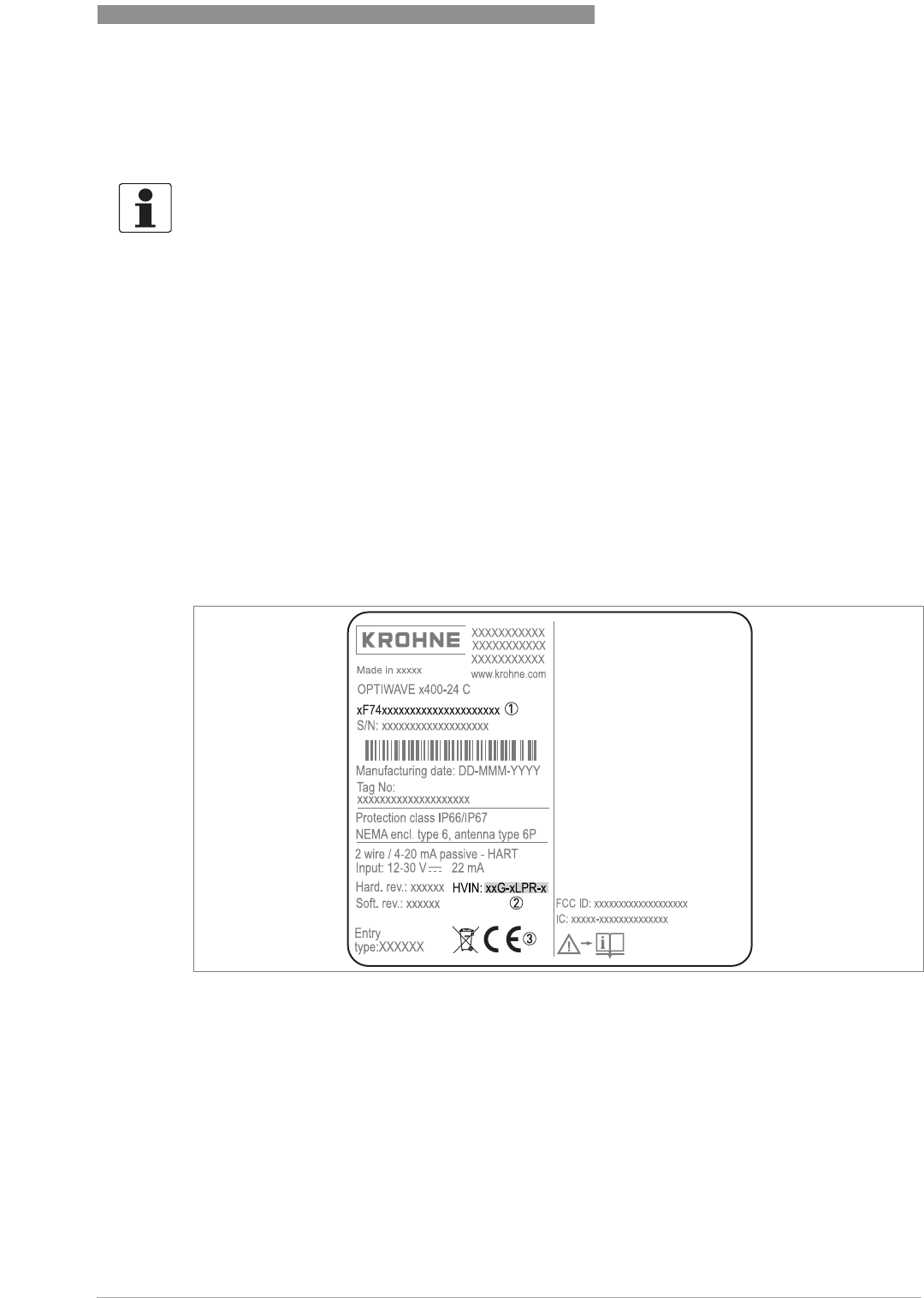
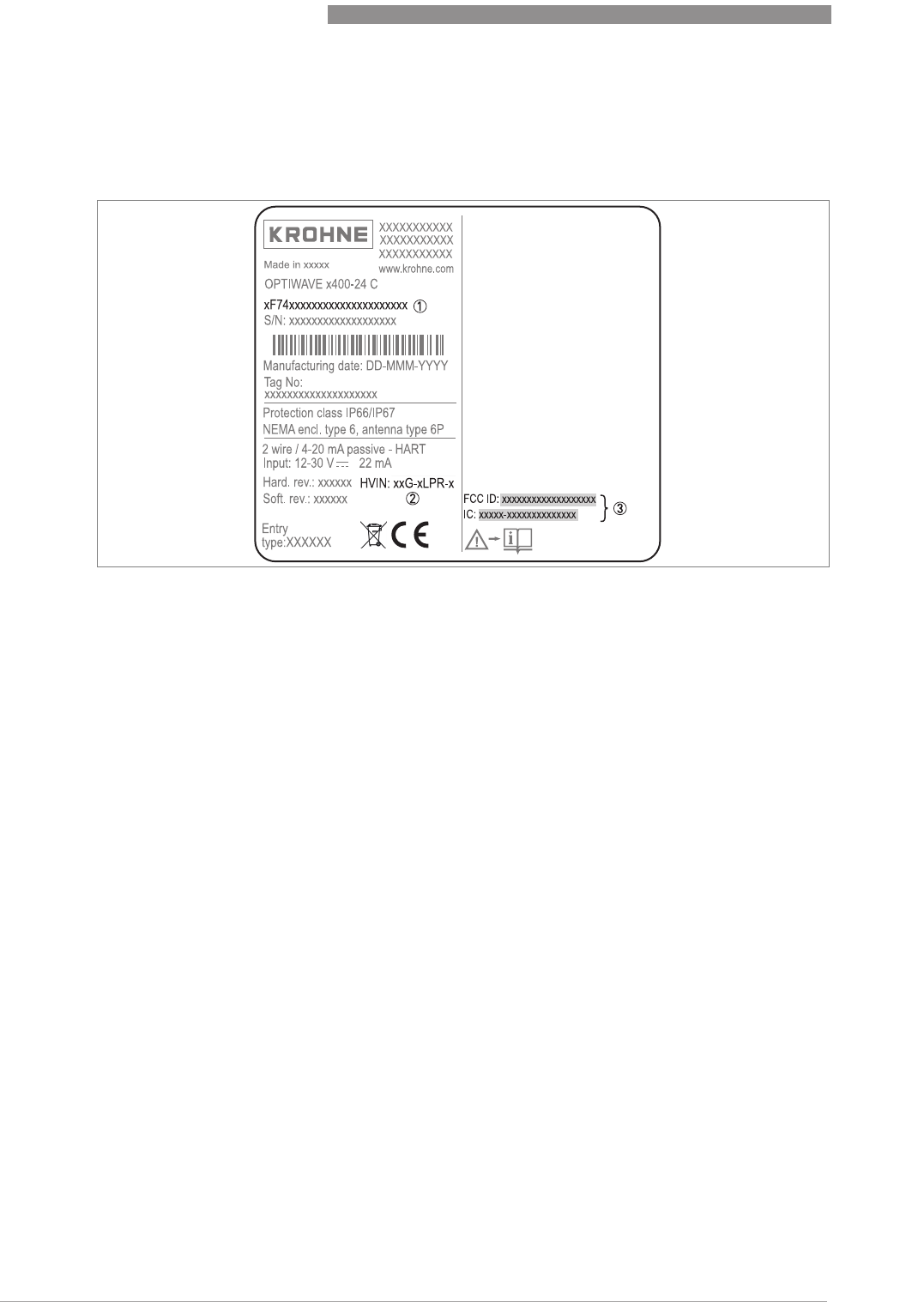
Figure 1-1: Radio approval information on the nameplate
1 Type code (defined in order)
2 HVIN (Hardware Version Identification Number). This number gives the radar signal frequency (24G = 24 GHz), the lo-
cation of the device (TLPR or LPR) and the type of signal converter (compact (C))
TLPR device: HVIN: 244G-TLPR-C
LPR device: HVIN: 24G-LPR-C
3 CE sign
1
SAFETY INSTRUCTIONS
10
OPTIWAVE 7400-24 C
www.krohne.com 12/2015 - 4003518001 - MA OPTIWAVE7400-24-R01-en
TLPR (Tank Level Probing Radar) devices only
Use approved personnel to install the device. The device and the tank agree with the R&TTE
directive if you obey the instructions that follow:
•TLPR (Tank Level Probing Radar) are required to be installed at a permanent fixed position at
a closed (not open) metallic tank or reinforced concrete tank, or similar enclosure structure
made of comparable attenuating material;
•flanges and attachments of the TLPR equipment shall provide the necessary microwave
sealing by design;
•sight glasses shall be coated with a microwave-proof coating when necessary (i.e. electrically
conductive coating);
•manholes or connection flanges at the tank shall be closed to ensure a low-level leakage of
the signal into the air outside the tank;
•whenever possible, mounting of the TLPR equipment shall be on top of the tank structure
with the orientation of the antenna to point in a downward direction;
•installation and maintenance of the TLPR equipment shall be performed by professionally
trained individuals only.
For data about how to install EMI/RFI shielding gaskets, refer to the instructions supplied with
this accessory.
LPR (Level Probing Radar) devices only
Use approved personnel to install the device. If the device is operated in the open air (outdoors),
it agrees with the R&TTE directive if you obey these instructions:
• The antenna must always point downwards. The boresight direction of the antenna must be
vertical. No other angles are permitted.
• Install the device more than 4 km / 2.485 mi away from radio astronomy sites.
• If the device is 4...40 km / 2.485...24.855 mi away from radio astronomy sites, do not install the
device more than 15 m / 49.21 ft above the ground.
Radio quiet zones: locations of radio astronomy sites (stations) in Europe and northern Eurasia
CAUTION!
If it is necessary to install the device less than 4 km / 2.485 mi from radio astronomy sites, you
must get the approval of the national regulatory authority before installation (e.g. ANFR
(France), Bundesnetzagentur (Germany), Ofcom (United Kingdom) etc.).
Country Name of the station Location
Latitude, ϕLongitude, λ
Finland Metsähovi 60°13'04" N 24°23'37" E
Tuorla 60°24'56" N 22°26'31" E
France Plateau de Bure 44°38'01" N 05°54'26" E
Floirac 44°50'10" N 00°31'37" W
Germany Effelsberg 50°31'32" N 06°53'00" E
Hungary Penc 47°47'22" N 19°16'53" E

SAFETY INSTRUCTIONS
1
11
OPTIWAVE 7400-24 C
www.krohne.com12/2015 - 4003518001 - MA OPTIWAVE7400-24-R01-en
Italy Medicina 44°31'14" N 11°38'49" E
Noto 36°52'34" N 14°59'21" E
Sardinia 39°29'50" N 09°14'40" E
Latvia Ventspils 57°33'12" N 21°51'17" E
Poland Kraków – Fort Skala 50°03'18" N 19°49'36" E
Torun – Piwnice 52°54'48" N 18°33'30" E
Russia Dmitrov 56°26'00" N 37°27'00" E
Kalyazin 57°13'22" N 37°54'01" E
Pushchino 54°49'00" N 37°40'00" E
Zelenchukskaya 43°49'53" N 41°35'32" E
Spain Yebes 40°31'27" N 03°05'22" W
Robledo 40°25'38" N 04°14'57" W
Switzerland Bleien 47°20’26" N 08°06’44" E
Sweden Onsala 57°23’45" N 11°55’35" E
UK Cambridge 52°09'59" N 00°02'20" E
Darnhall 53°09'22" N 02°32'03" W
Jodrell Bank 53°14'10" N 02°18'26" W
Knockin 52°47'24" N 02°59'45" W
Pickmere 53°17'18" N 02°26'38" W
Country Name of the station Location
Latitude, ϕLongitude, λ

1
SAFETY INSTRUCTIONS
12
OPTIWAVE 7400-24 C
www.krohne.com 12/2015 - 4003518001 - MA OPTIWAVE7400-24-R01-en
1.5.2 U.S.A. and Canada
This level transmitter is approved to be used outside metallic tanks. If you use the device in the
open air, read the device nameplate to make sure that the device can be used for your
application:
INFORMATION!
LPR (Level Probing Radar)
LPR (Level Probing Radar)LPR (Level Probing Radar)
LPR (Level Probing Radar) equipment are devices for the measurement of level in the open air
or in a closed space (a metallic tank etc.). TLPR (Tank Llevel Probing Radar)
TLPR (Tank Llevel Probing Radar)TLPR (Tank Llevel Probing Radar)
TLPR (Tank Llevel Probing Radar) equipment are
devices for the measurement of level in a closed space only.
For more data about the order code, refer to Order code on page 122
.
LEGAL NOTICE!
FCC
FCCFCC
FCC
This device complies with Part 15 of the FCC Rules. Operation is subject to the following two
conditions:
1. This device may not cause harmful interference, and
2. This device must accept any interference received, including interference which may cause un-
desired operation.
Changes or modifications made to this equipment not expressly approved by the manufacturer
may void the FCC authorizations to operate this equipment.
This equipment has been tested and found to comply with the limits for a Class B digital device,
pursuant to Part 15 of the FCC Rules. These limits are designed to provide reasonable protection
against harmful interference in a residential installation. This equipment generates, uses and
can radiate radio frequency energy and, if not installed and used in accordance with the
instructions, may cause harmful interference to radio communications. However, there is no
guarantee that interference will not occur in a particular installation. If this equipment does
cause harmful interference to radio or television reception, which can be determined by turning
the equipment off and on, the user is encouraged to try to correct the interference by one or
more of the following measures:
•
Reorient or relocate the receiving antenna.
•
Increase the separation between the equipment and receiver.
•
Connect the equipment into an outlet on a circuit different from that to which the receiver is
connected.
•
Consult the dealer or an experienced radio/TV technician for help.

SAFETY INSTRUCTIONS
1
13
OPTIWAVE 7400-24 C
www.krohne.com12/2015 - 4003518001 - MA OPTIWAVE7400-24-R01-en
The Product Marketing Name (PMN) of this device is "Optiwave x400-24 series".
This level transmitter is approved to be used outside metallic tanks. If you use the device in the
open air, read the device nameplate to make sure that the device can be used for your
application. Only the antennas that follow are permitted for open-air applications:
•VF744xxxx4xxx...
•VF744xxxx5xxx...
•VF744xxxx6xxx...
•VF744xxxx7xxx...
•VF744xxxxAxxx...
•VF744xxxxBxxx...
•VF744xxxxCxxx...
•VF744xxxxDxxx...
•VF744xxxxExxx...
•VF744xxxxGxxx...
•VF744xxxxHxxx...
•VF744xxxxKxxx...
•VF744xxxxPxxx...
•VF744xxxxRxxx...
•VF744xxxxSxxx...
LEGAL NOTICE!
IC
ICIC
IC
This device complies with Industry Canada licence-exempt RSS standard(s).
Operation is subject to the following conditions:
1. this device may not cause harmful interference, and
2. this device must accept any interference received, including interference that may cause un-
desired operation.
This device and the handbook complies with the requirements of RSS-Gen. Operation is subject
to the conditions that follow:
1. The installation of the LPR/TLPR device shall be done by trained installers, in strict compliance
with the manufacturer
’
s instructions.
2. The use of this device is on a "no-interference, no-protection" basis. That is, the user shall ac-
cept operations of high-powered radar in the same frequency band which may interfere with or
damage this device. However, devices found to interfere with primary licensing operations will
be required to be removed at the user
’
s expense.
3. The TLPR device shall be installed and operated in a completely enclosed container to prevent
RF emissions, which can otherwise interfere with aeronautical navigation.
4. LPR devices: Ensure a vertically downward orientation of the transmit antenna and a installa-
tion only at fixed locations.
5. The installer / user of this device shall ensure that it is at least 10 km from the Dominion Radio
Astrophysical Observatory (DRAO) near Penticton, British Columbia. The coordinates of the
DRAO are latitude 49
°
19'15" N and longitude 119
°
37'12" W. For devices not meeting this 10 km
separation (e.g. those in the Okanagan Valley, British Columbia) the installer / user must coor-
dinate with, and obtain the written concurrence of, the Director of the DRAO before the equip-
ment can be installed or operated. The Director of the DRAO may be contacted at 250-497-2300
(tel.) or 250-497-2355 (fax). Alternatively, the Manager, Regulatory Standards, Industry Canada,
may be contacted.
1
SAFETY INSTRUCTIONS
14
OPTIWAVE 7400-24 C
www.krohne.com 12/2015 - 4003518001 - MA OPTIWAVE7400-24-R01-en
•VF744xxxxTxxx...
•VF744xxxxUxxx...
Figure 1-2: FCC ID and IC number
1 Type code (defined in order)
2 HVIN (Hardware Version Identification Number). This number gives the radar signal frequency (24G = 24 GHz), the lo-
cation of the device (TLPR or LPR) and the type of signal converter (compact (C))
TLPR device: HVIN: 24G-TLPR-C
LPR device: HVIN: 24G-LPR-C
3 FCC ID and IC number
TLPR device: FCC-ID:Q6BFMCW24G74T, IC number: 1991D-FMCW24G74T
LPR device: FCC-ID: Q6BFMCW24G74L, IC number:1991D-FMCW24G74L

SAFETY INSTRUCTIONS
1
15
OPTIWAVE 7400-24 C
www.krohne.com12/2015 - 4003518001 - MA OPTIWAVE7400-24-R01-en
1.6 Safety instructions from the manufacturer
1.6.1 Copyright and data protection
The contents of this document have been created with great care. Nevertheless, we provide no
guarantee that the contents are correct, complete or up-to-date.
The contents and works in this document are subject to copyright. Contributions from third
parties are identified as such. Reproduction, processing, dissemination and any type of use
beyond what is permitted under copyright requires written authorisation from the respective
author and/or the manufacturer.
The manufacturer tries always to observe the copyrights of others, and to draw on works created
in-house or works in the public domain.
The collection of personal data (such as names, street addresses or e-mail addresses) in the
manufacturer's documents is always on a voluntary basis whenever possible. Whenever
feasible, it is always possible to make use of the offerings and services without providing any
personal data.
We draw your attention to the fact that data transmission over the Internet (e.g. when
communicating by e-mail) may involve gaps in security. It is not possible to protect such data
completely against access by third parties.
We hereby expressly prohibit the use of the contact data published as part of our duty to publish
an imprint for the purpose of sending us any advertising or informational materials that we have
not expressly requested.
1.6.2 Disclaimer
The manufacturer will not be liable for any damage of any kind by using its product, including,
but not limited to direct, indirect or incidental and consequential damages.
This disclaimer does not apply in case the manufacturer has acted on purpose or with gross
negligence. In the event any applicable law does not allow such limitations on implied warranties
or the exclusion of limitation of certain damages, you may, if such law applies to you, not be
subject to some or all of the above disclaimer, exclusions or limitations.
Any product purchased from the manufacturer is warranted in accordance with the relevant
product documentation and our Terms and Conditions of Sale.
The manufacturer reserves the right to alter the content of its documents, including this
disclaimer in any way, at any time, for any reason, without prior notification, and will not be liable
in any way for possible consequences of such changes.

1
SAFETY INSTRUCTIONS
16
OPTIWAVE 7400-24 C
www.krohne.com 12/2015 - 4003518001 - MA OPTIWAVE7400-24-R01-en
1.6.3 Product liability and warranty
The operator shall bear responsibility for the suitability of the device for the specific purpose.
The manufacturer accepts no liability for the consequences of misuse by the operator. Improper
installation or operation of the devices (systems) will cause the warranty to be void. The
respective "Standard Terms and Conditions" which form the basis for the sales contract shall
also apply.
1.6.4 Information concerning the documentation
To prevent any injury to the user or damage to the device it is essential that you read the
information in this document and observe applicable national standards, safety requirements
and accident prevention regulations.
If this document is not in your native language and if you have any problems understanding the
text, we advise you to contact your local office for assistance. The manufacturer can not accept
responsibility for any damage or injury caused by misunderstanding of the information in this
document.
This document is provided to help you establish operating conditions, which will permit safe and
efficient use of this device. Special considerations and precautions are also described in the
document, which appear in the form of icons as shown below.
SAFETY INSTRUCTIONS
1
17
OPTIWAVE 7400-24 C
www.krohne.com12/2015 - 4003518001 - MA OPTIWAVE7400-24-R01-en
1.6.5 Warnings and symbols used
Safety warnings are indicated by the following symbols.
• HANDLING
HANDLINGHANDLING
HANDLING
This symbol designates all instructions for actions to be carried out by the operator in the
specified sequence.
iRESULT
RESULTRESULT
RESULT
This symbol refers to all important consequences of the previous actions.
1.7 Safety instructions for the operator
DANGER!
This warning refers to the immediate danger when working with electricity.
DANGER!
This warning refers to the immediate danger of burns caused by heat or hot surfaces.
DANGER!
This warning refers to the immediate danger when using this device in a hazardous atmosphere.
DANGER!
These warnings must be observed without fail. Even partial disregard of this warning can lead to
serious health problems and even death. There is also the risk of seriously damaging the device
or parts of the operator's plant.
WARNING!
Disregarding this safety warning, even if only in part, poses the risk of serious health problems.
There is also the risk of damaging the device or parts of the operator's plant.
CAUTION!
Disregarding these instructions can result in damage to the device or to parts of the operator's
plant.
INFORMATION!
These instructions contain important information for the handling of the device.
LEGAL NOTICE!
This note contains information on statutory directives and standards.
WARNING!
In general, devices from the manufacturer may only be installed, commissioned, operated and
maintained by properly trained and authorized personnel.
This document is provided to help you establish operating conditions, which will permit safe and
efficient use of this device.
2
DEVICE DESCRIPTION
18
OPTIWAVE 7400-24 C
www.krohne.com 12/2015 - 4003518001 - MA OPTIWAVE7400-24-R01-en
2.1 Scope of delivery
INFORMATION!
Do a check of the packing list to make sure that you have all the elements given in the order.
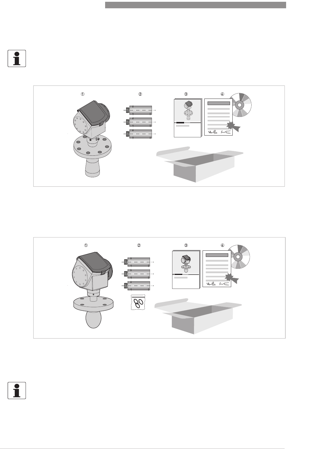
Scope of delivery – horn antenna
Figure 2-1: Scope of delivery – horn antenna
1 Signal converter and antenna in compact version
2 Antenna extensions (option)
3 Quick Start
4 DVD-ROM (including Handbook, Quick Start, Technical Datasheet and related software)
Scope of delivery – Drop antenna
Figure 2-2: Scope of delivery – Drop antenna
1 Signal converter and antenna in compact version
2 Antenna extensions (option) and O-ring for each antenna extension
3 Quick Start
4 DVD-ROM (including Handbook, Quick Start, Technical Datasheet, and related software)
INFORMATION!
No special tools or training required!

DEVICE DESCRIPTION
2
19
OPTIWAVE 7400-24 C
www.krohne.com12/2015 - 4003518001 - MA OPTIWAVE7400-24-R01-en
2.2 Device description
This device is a 24 GHz FMCW-radar level transmitter. It is a non-contact technology and is 2-
wire loop-powered. It is designed to measure the distance, level, mass, volume and reflectivity of
liquids, pastes and slurries.
Radar level transmitters use an antenna to emit a signal to the surface of the measured product.
The device has many antennas available. Thus, it can measure most products even in difficult
conditions. Also refer to
Technical data
on page 90.
If it is ordered with the applicable options, it can be certified for use in hazardous areas.
These output options are available:
•1 output: 4...20 mA (HART)
•2-wire FOUNDATION™ Fieldbus output
•2-wire PROFIBUS PA output
These accessories are available:
•Stainless steel weather protection.
•RS232 / HART
®
converter (VIATOR).
•USB / HART
®
converter.
INFORMATION!
For more data on accessories, refer to Accessories on page 134
.
2
DEVICE DESCRIPTION
20
OPTIWAVE 7400-24 C
www.krohne.com 12/2015 - 4003518001 - MA OPTIWAVE7400-24-R01-en
2.3 Visual Check
If the device is supplied with an FKM/FPM gasket, there is no symbol on the side of the process
connection.
WARNING!
If the display screen glass is broken, do not touch.
INFORMATION!
Inspect the packaging carefully for damages or signs of rough handling. Report damage to the
carrier and to the local office of the manufacturer.
Figure 2-3: Visual check
1 Device nameplate (for more data refer to
Nameplate (examples)
on page 21)
2 Process connection data (size and pressure rating, material reference and heat number)
3 Gasket material data – refer to the illustration that follows
INFORMATION!
Look at the device nameplate to ensure that the device is delivered according to your order.
Check for the correct supply voltage printed on the nameplate.
INFORMATION!
Compare the material references on the side of the process connection with the order.

DEVICE DESCRIPTION
2
21
OPTIWAVE 7400-24 C
www.krohne.com12/2015 - 4003518001 - MA OPTIWAVE7400-24-R01-en
2.4 Nameplates
2.4.1 Nameplate (examples)
INFORMATION!
Look at the device nameplate to ensure that the device is delivered according to your order.
Check for the correct supply voltage printed on the nameplate.
Figure 2-4: Compact (C) and remote (F) versions: Non-Ex nameplate attached to the housing
1 Cable entry size
2 Input / output option
3 Degree of ingress protection (according to EN 60529 / IEC 60529)
4 Customer tag number
5 Date of manufacture
6 Order number
7 Type code (defined in order)
8 Model name and number. The last letter "X" is either:
C = compact version or
F = remote (field) version
9 Company name and address

2
DEVICE DESCRIPTION
22
OPTIWAVE 7400-24 C
www.krohne.com 12/2015 - 4003518001 - MA OPTIWAVE7400-24-R01-en
Figure 2-5: Remote (F) version: Non-Ex nameplate attached to the antenna assembly
1 Cable entry size
2 Degree of ingress protection (according to EN 60529 / IEC 60529)
3 Date of manufacture
4 Order number
5 Type code (defined in order)
6 Model name and number
7 Company name and address
INSTALLATION
3
23
OPTIWAVE 7400-24 C
www.krohne.com12/2015 - 4003518001 - MA OPTIWAVE7400-24-R01-en
3.1 General notes on installation
3.2 Storage
•Store the device in a dry and dust-free location.
•Keep the converter out of the sunlight.
•Store the device in its original packing.
INFORMATION!
Inspect the packaging carefully for damages or signs of rough handling. Report damage to the
carrier and to the local office of the manufacturer.
INFORMATION!
Do a check of the packing list to make sure that you have all the elements given in the order.
INFORMATION!
Look at the device nameplate to ensure that the device is delivered according to your order.
Check for the correct supply voltage printed on the nameplate.
WARNING!
Do not keep the device in a vertical position. This will damage the antenna and the device will not
measure correctly.
Figure 3-1: Storage conditions
1 When you put the device into storage, do not keep it in a vertical position
2 Put the device on its side. We recommend that you use the packaging in which it was delivered.
3 Storage temperature range: -40...+85°C / -40...+185°F
3
INSTALLATION
24
OPTIWAVE 7400-24 C
www.krohne.com 12/2015 - 4003518001 - MA OPTIWAVE7400-24-R01-en
3.3 Transport
3.4 Pre-installation requirements
•Make sure that there is sufficient space on all sides.
•Protect the signal converter from direct sunlight.
•Do not subject the signal converter to heavy vibrations.
Figure 3-2: How to lift the device
1 Remove the converter before you lift the device with a hoist.
WARNING!
Lift the device carefully to prevent damage to the antenna.
INFORMATION!
Obey the precautions that follow to make sure that the device is correctly installed.
INSTALLATION
3
25
OPTIWAVE 7400-24 C
www.krohne.com12/2015 - 4003518001 - MA OPTIWAVE7400-24-R01-en
3.5 Pressure and temperature ranges
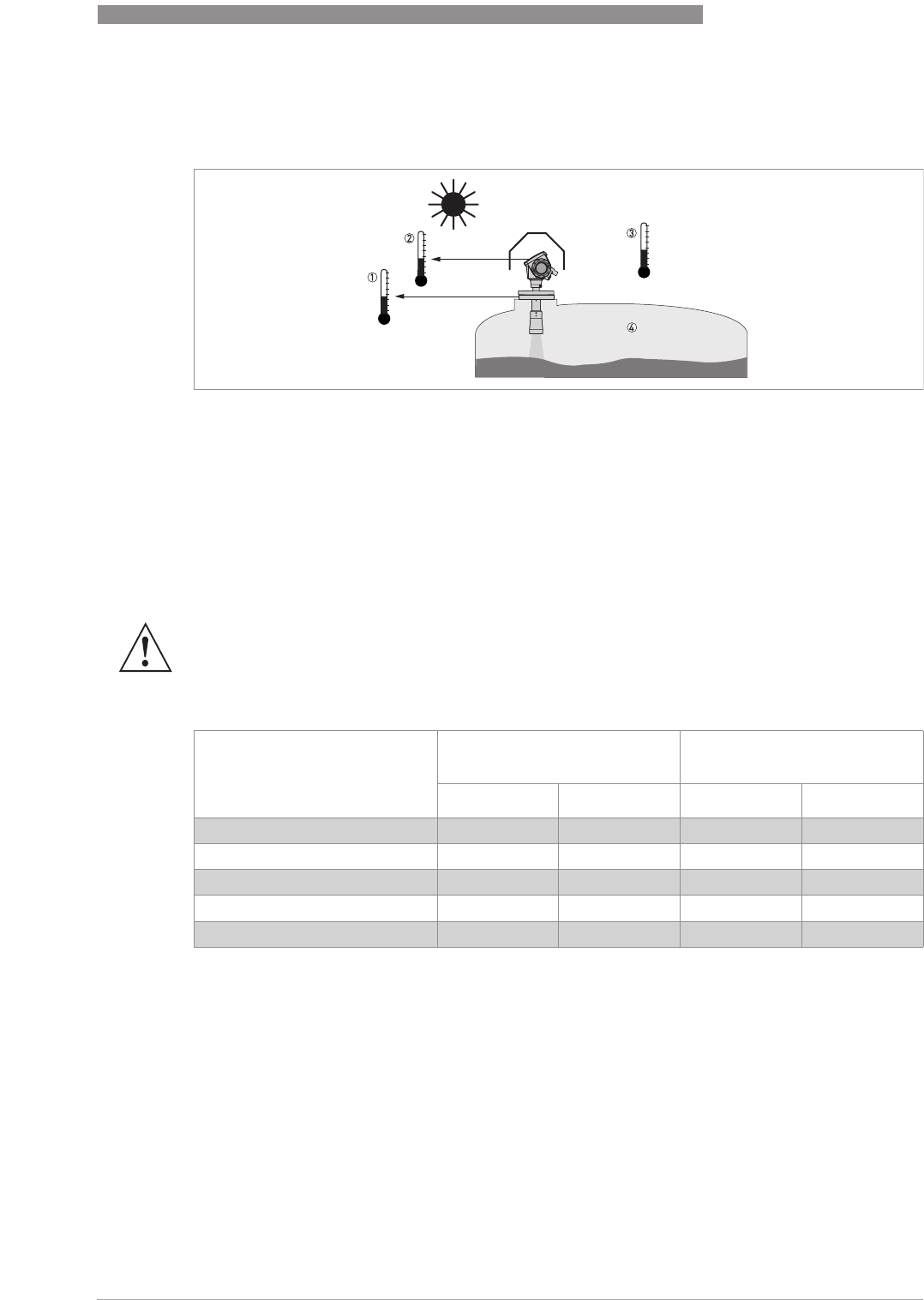
Figure 3-3: Pressure and temperature ranges
1 Flange temperature
FKM/FPM gasket: -40...+200°C / -40...+390°F; Kalrez
®
6375 gasket: -20...+200°C / -4...+390°F;
EPDM gasket: -50...+150°C / -58...+300°F
Ex devices: see supplementary operating instructions
2 Ambient temperature for operation of the display
-20...+60°C / -4...+140°F
If the ambient temperature is not between these limits, the display screen switches off automatically
3 Ambient temperature
Non-Ex devices: -40...+80°C / -40...+175°F
Ex devices: see supplementary operating instructions
WARNING!
The process connection temperature range must agree with the temperature limits of the
gasket material. The operating pressure range is subject to the process connection used and the
flange temperature.
Antenna type Maximum process connection
temperature
Maximum operating pressure
[°C] [°F] barg psig
PP Drop +100 +210 16 232
PTFE Drop +150 +300 40 580
PEEK Drop +xxx +xxx xx xxx
Hygienic +150 +300 10 145
Horn / Sheet metal horn +200 1 +300 1 40 (100) 2 580 (1450) 2
1The maximum process connection temperature must agree with the temperature limits of the gasket material. If the
distance piece option is not attached, the maximum process connection temperature is +150°C / +300°F.
2Standard operating pressure: 40 barg / 580 psig. Optional max. operating pressure: 100 barg / 1450 psig.
3
INSTALLATION
26
OPTIWAVE 7400-24 C
www.krohne.com 12/2015 - 4003518001 - MA OPTIWAVE7400-24-R01-en
3.6 Recommended mounting position
We recommend that you prepare the installation when the tank is empty.
3.6.1 General data
CAUTION!
Follow these recommendations to make sure that the device measures correctly. They have an
effect on the performance of the device.
INFORMATION!
If possible, do not install a nozzle on the tank centerline.
Figure 3-4: Recommended nozzle position for liquids, pastes and slurries
1 Nozzles for DN40 or DN50 Horn antennas, or DN50 Hygienic antenna
2 Nozzles for DN80, DN100, DN150 or DN200 Horn antennas and DN80 or DN150 Drop antennas
3 Tank height
4 Tank diameter
5 Minimum distance of nozzle from the tank wall : 1/7 × tank height
Maximum distance of nozzle from the tank wall : 1/3 × tank diameter
6 Minimum distance of nozzle from the tank wall : 1/10 × tank height
Maximum distance of nozzle from the tank wall : 1/3 × tank diameter
INSTALLATION
3
27
OPTIWAVE 7400-24 C
www.krohne.com12/2015 - 4003518001 - MA OPTIWAVE7400-24-R01-en
3.6.2 Tanks with conical bottoms
Figure 3-5: More than 1 FMCW radar level meter can be operated in a tank
Figure 3-6: Tanks with conical bottoms
Conical bottoms have an effect on the measuring range. The device cannot measure to the bottom of the tank.
1 Axis of radar beam
2 Minimum level reading
3
INSTALLATION
28
OPTIWAVE 7400-24 C
www.krohne.com 12/2015 - 4003518001 - MA OPTIWAVE7400-24-R01-en
3.7 Mounting restrictions
We recommend that you prepare the installation when the tank is empty.
3.7.1 General data
3.7.2 Obstacles in the tank
Obstacles in the tank can cause parasitic signals. They have an effect on the performance of the
device.
Do an Empty Spectrum recording (refer to Operation
OperationOperation
Operation) to remove parasitic signals with a filter.
CAUTION!
Follow these recommendations to make sure that the device measures correctly. They have an
effect on the performance of the device.
Figure 3-7: General Installation recommendations
1 Do not tilt the device more than 2°
2 We recommend that you do an empty spectrum recording if there are too many obstacles in the radar beam (for more
data, refer to
How to make a filter to remove radar signal interference
on page 77). If necessary, install a bypass cham-
ber or stilling well or use an "L" antenna extension (the device must be installed on the side of the tank) to move the
device away from obstacles.
3 2.5 mm / 0.1¨ max. for high-dielectric constant liquids
4 Curved and conical tank bottoms. For fine adjustment of the device, refer to
How to measure correctly in tanks with
curved or conical bottoms
on page 78.
5 Beam radius (DN40 horn antenna): increments of 180 mm/m or 2.15¨/ft (10°)
Beam radius (DN50 horn antenna or DN50 Hygienic antenna): increments of 130 mm/m or 1.55¨/ft (7.5°)
Beam radius (DN80 horn antenna): increments of 90 mm/m or 1.1¨/ft (5°)
Beam radius (DN100 horn antenna or DN80 Drop antenna): increments of 70 mm/m or 0.83¨/ft (4°)
Beam radius (DN150 horn antenna): increments of 52.5 mm/m or 0.63¨/ft (3°)
Beam radius (DN150 Drop antenna or DN200 horn antenna): increments of 35 mm/m or 0.42¨/ft (2°)
CAUTION!
If there are parasitic signals, the device will not measure correctly. Parasitic signals are caused
by:
•
Objects in the tank.
•
Sharp corners that are perpendicular to the path of the radar beam.
INSTALLATION
3
29
OPTIWAVE 7400-24 C
www.krohne.com12/2015 - 4003518001 - MA OPTIWAVE7400-24-R01-en
3.7.3 Devices with Metallic Horn antenna
The antenna must project out of the nozzle. If necessary, use an antenna extension. But if the
tank roof is flat and the tank fitting is symmetrical, it is not necessary for the antenna to project
out of the nozzle. Thus, the device can have a larger measuring range.
Figure 3-8: Obstacles in the tank
Do not put the device directly above obstacles (agitator, support beams, heating tubes etc.). Parasitic signals from obsta-
cles will cause the device to measure incorrectly.
1 Solution 1: Put the device on another process connection away from obstacles
2 Solution 2: Attach the device to the side of the tank and use an "L" (right angle) extension
CAUTION!
Do not put the device near to the product inlet. If the product that enters the tank touches the
antenna, the device will measure incorrectly. If the product fills the tank directly below the
antenna, the device will also measure incorrectly.
Figure 3-9: Product inlets
1 The device is in the correct position.
2 The device is too near to the product inlet.
3
INSTALLATION
30
OPTIWAVE 7400-24 C
www.krohne.com 12/2015 - 4003518001 - MA OPTIWAVE7400-24-R01-en
3.7.4 Process connections
Equipment needed:
•Device
•Flange gasket (not supplied)
•Wrench (not supplied)
• Make sure the flange on the nozzle is level.
• Make sure that you use the applicable gasket for the flange dimensions and the process.
• Align the gasket correctly on the flange facing of the nozzle.
• Lower the antenna carefully into the tank.
• Make sure that you point the device in the correct direction. Refer to "Point the device in the
correct direction" in this section.
• Tighten the flange bolts.
iRefer to local rules and regulations for the correct torque to apply to the bolts.
Requirements for flange connections
Figure 3-10: Flange connection
INSTALLATION
3
31
OPTIWAVE 7400-24 C
www.krohne.com12/2015 - 4003518001 - MA OPTIWAVE7400-24-R01-en
Equipment needed:
•Device
•Gasket for G 1½ connection (not supplied)
•Thread seal tape (PTFE) for 1½NPT connection (not supplied)
•50 mm / 2¨ wrench (not supplied)
• Make sure the tank connection is level.
• ISO 228-1 (G) connection:
ISO 228-1 (G) connection:ISO 228-1 (G) connection:
ISO 228-1 (G) connection: Make sure that you use the applicable gasket for the connection
dimensions and the process.
• ISO 228-1 (G) connection:
ISO 228-1 (G) connection:ISO 228-1 (G) connection:
ISO 228-1 (G) connection: Align the gasket correctly.
• NPT connection:
NPT connection:NPT connection:
NPT connection: Wind the thread seal tape around the process connection in agreement with
good engineering practice.
• Lower the antenna carefully into the tank.
• Turn the threaded connection on the antenna to attach the device to the process connection.
• Make sure that you point the device in the correct direction. Refer to "Point the device in the
correct direction" in this section.
• Tighten the connection to the correct torque (not more than 40 Nm).
3.7.5 Standpipes (stilling wells and bypass chambers)
Use a standpipe if:
•There is highly conductive foam in the tank.
•The liquid is very turbulent or agitated.
•There are too many other objects in the tank.
•The device is measuring a liquid (petro-chemicals) in a tank with a floating roof.
•The device is installed in a horizontal cylindrical tank (refer to the end of this section)
Requirements for threaded connections
Figure 3-11: Threaded connection
WARNING!
Do not tighten the connection to a torque more than 40 Nm. If the connection is too tight, this will
damage the thread.
To prevent damage to the antenna, make sure that the minimum diameter of the hole for a
1
½
NPT thread connection is not less than 43.4 mm / 1.71
¨
.
3
INSTALLATION
32
OPTIWAVE 7400-24 C
www.krohne.com 12/2015 - 4003518001 - MA OPTIWAVE7400-24-R01-en
Stilling wells - general notes
Installation in tanks containing one liquid and foam
• Drill an air circulation hole (max. Ø10 mm / 0.4¨) in the stilling well above the maximum level.
• Remove the burr from the hole.
Installation in tanks containing one liquid or more without foam
• Drill an air circulation hole (max. Ø10 mm / 0.4¨) in the stilling well above the maximum level.
• Drill 1 or more liquid circulation holes in the stilling well (if there is more than 1 liquid in the
tank).
iThese holes help the liquid to move freely between the stilling well and the tank.
• Remove the burr from the hole.
Stilling wells: floating roofs
If the device must be installed on a tank with a floating roof, install it in a stilling well.
Figure 3-12: Installation recommendations for standpipes (stilling wells and bypass chambers)
1 A stilling well solution
2 A bypass chamber solution
3 Air circulation hole
4 Level of the liquid
CAUTION!
•
The standpipe must be electrically conductive.
•
The inside diameter of the standpipe must not be more than 5 mm / 0.2
¨
over the diameter of
the antenna (for a high-dielectric constant liquid).
•
The standpipe must be straight. There must be no sudden changes in internal diameter
greater than 1 mm / 0.04
¨
.
•
The standpipe must be vertical.
•
Recommended surface roughness: <
±
0.1 mm / 0.004
¨
.
•
Make sure that there are no deposits at the bottom of the standpipe.
•
Make sure that there is liquid in the standpipe.

INSTALLATION
3
33
OPTIWAVE 7400-24 C
www.krohne.com12/2015 - 4003518001 - MA OPTIWAVE7400-24-R01-en
Stilling wells: horizontal cylindrical tanks
We recommend that you install the device in a stilling well if the device:
•is for a horizontal cylindrical tank,
•is in a metallic tank,
•measures a product with a high dielectric constant and
•is on the centerline of the tank.
Figure 3-13: Floating roofs
1 Sediment
2 Support fixtures
3 Stilling well
4 Floating roof
5 Product
6 Tank
Figure 3-14: Horizontal cylindrical tanks
1 The device is installed without a stilling well. There are multiple reflections. Refer to the CAUTION! that follows.
2 The device is installed in a stilling well and measures correctly.
3
INSTALLATION
34
OPTIWAVE 7400-24 C
www.krohne.com 12/2015 - 4003518001 - MA OPTIWAVE7400-24-R01-en
Bypass chambers
Installation next to tanks containing one liquid and foam
•The top process connection of the bypass chamber must be above the maximum level of
liquid.
•The bottom process connection of the bypass chamber must be below the lowest measured
level of liquid.
Installation next to tanks containing more than one liquid
•The top process connection of the bypass chamber must be above the maximum level of
liquid.
•The bottom process connection of the bypass chamber must be below the lowest measured
level of liquid.
•Additional process connections are necessary for the liquids to circulate freely along the
length of the bypass chamber.
CAUTION!
If the device is installed in horizontal cylindrical tank that contains a high dielectric constant
liquid without a stilling well, do not put it on the tank centerline. This will cause multiple
reflections and the device will not measure accurately. Use the 2.5.8 Multiple Reflections
2.5.8 Multiple Reflections2.5.8 Multiple Reflections
2.5.8 Multiple Reflections
function in Supervisor > Application
Supervisor > ApplicationSupervisor > Application
Supervisor > Application to keep the effects of multiple reflections to a minimum. For
more data,<Function Description> (2. Supervisor).
Figure 3-15: Installation recommendations for bypass chambers that contain more than one liquid
1 Bypass chamber
2 Additional process connection
INSTALLATION
3
35
OPTIWAVE 7400-24 C
www.krohne.com12/2015 - 4003518001 - MA OPTIWAVE7400-24-R01-en
3.8 How to attach antenna extensions
Equipment needed:
•3 mm Allen wrench (not supplied)
Equipment needed (not supplied):
•Torque wrench 200 Nm (for the H30 head of the Drop antenna sub-assembly)
•3mm Allen wrench
Horn antenna - antenna extensions
Figure 3-16: Horn antenna - how to attach antenna extensions
INFORMATION!
Drop antenna:
Drop antenna:Drop antenna:
Drop antenna: Antenna extensions can only be attached below flanges without the PP/PTFE
flange plate option
CAUTION!
Drop antenna:
Drop antenna:Drop antenna:
Drop antenna: Make sure that there are not more than 5 antenna extensions attached to a device
with a Drop antenna. If there are more than 5 antenna extensions, the device will not measure
correctly.
Make sure that you put an O-ring 4 into the groove at the top of each antenna extension.
3
INSTALLATION
36
OPTIWAVE 7400-24 C
www.krohne.com 12/2015 - 4003518001 - MA OPTIWAVE7400-24-R01-en
3.9 How to turn or remove the signal converter
INFORMATION!
The converter turns 360
°
. The converter can be removed from the process connection assembly
under process conditions.
Figure 3-17: How to turn or remove the signal converter
1 Tool: 5 mm Allen wrench (not supplied)
2 Cover for the wave guide hole on top of the process connection assembly (not supplied)
CAUTION!
If you remove the converter, put a cover on the wave guide hole on top of the process connection
assembly.
When the converter is attached to the process connection assembly, tighten the lock screw.

INSTALLATION
3
37
OPTIWAVE 7400-24 C
www.krohne.com12/2015 - 4003518001 - MA OPTIWAVE7400-24-R01-en
3.10 How to assemble the remote version
• Attach the wall bracket 1 to the flexible conduit.
• Tighten the locking nut 2 with a 24 mm wrench.
• Attach the wall bracket to a wall or pipe (DN50...100 / 2¨...4¨) 3.
• Loosen the housing locking screw 4 with a 5 mm Allen wrench.
• Remove the housing 5.

3
INSTALLATION
38
OPTIWAVE 7400-24 C
www.krohne.com 12/2015 - 4003518001 - MA OPTIWAVE7400-24-R01-en
• Attach the housing to the flexible conduit 6.
• Tighten the housing locking screw 7.
• Attach the flexible conduit to the probe 8.
• Tighten the flexible conduit locking screw 9.
INSTALLATION
3
39
OPTIWAVE 7400-24 C
www.krohne.com12/2015 - 4003518001 - MA OPTIWAVE7400-24-R01-en
You can attach the wall bracket of the remote housing to a wall or pipe (DN50...100 / 2¨...4¨).
These are the dimensions:
Dimensions in mm
Dimensions in inches
3.11 Weather protection
3.11.1 How to attach the weather protection to the device
Equipment needed:
•Device.
•Weather protection (option).
•10 mm wrench (not supplied).
The overall dimensions of the weather protection are.
• Loosen the bracket nuts on the weather protection.
• Remove the bracket.
• Lower the weather protection onto the device.
• Turn the weather protection so that the keyhole points forward.
• Attach the bracket.
• Lift the weather protection to the top of the housing support pillar.
• Hold the weather protection in the correct position and tighten the bracket nuts.
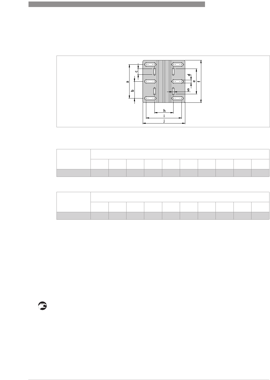
Figure 3-18: Dimensions of the wall bracket
Dimensions [mm]
a b c d e f g h i j
Wall bracket 120 60 20 11 90 150 667.4 126.4 150.4
Dimensions [inches]
a b c d e f g h i j
Wall bracket 4.7 2.4 0.8 0.4 3.5 5.9 0.2 2.65 4.98 5.92

3
INSTALLATION
40
OPTIWAVE 7400-24 C
www.krohne.com 12/2015 - 4003518001 - MA OPTIWAVE7400-24-R01-en
3.11.2 How to open the weather protection
Equipment needed:
•Weather protection attached to the device.
•Large slotted tip screwdriver (not supplied).
• Put a large slotted tip screwdriver into the keyhole at the front of the weather protection. Turn
the screwdriver counterclockwise.
• Pull the top of weather protection up and forward.
iThis will open the weather protection.
ELECTRICAL CONNECTIONS
4
41
OPTIWAVE 7400-24 C
www.krohne.com12/2015 - 4003518001 - MA OPTIWAVE7400-24-R01-en
4.1 Safety instructions
4.2 Electrical installation: 2-wire, loop-powered
4.2.1 Compact version
DANGER!
All work on the electrical connections may only be carried out with the power disconnected. Take
note of the voltage data on the nameplate!
DANGER!
Observe the national regulations for electrical installations!
DANGER!
For devices used in hazardous areas, additional safety notes apply; please refer to the Ex
documentation.
WARNING!
Observe without fail the local occupational health and safety regulations. Any work done on the
electrical components of the measuring device may only be carried out by properly trained
specialists.
INFORMATION!
Look at the device nameplate to ensure that the device is delivered according to your order.
Check for the correct supply voltage printed on the nameplate.
Terminals for electrical installation
Figure 4-1: Terminals for electrical installation
1 Grounding terminal in the housing (if the electrical cable is shielded)
2 Current output -
3 Current output +
4 Location of the external grounding terminal (at the bottom of the converter)
INFORMATION!
Electrical power to the output terminal energizes the device. The output terminal is also used for
HART
®
communication.
4
ELECTRICAL CONNECTIONS
42
OPTIWAVE 7400-24 C
www.krohne.com 12/2015 - 4003518001 - MA OPTIWAVE7400-24-R01-en
1 Loosen the lock screw with a 2.5 mm Allen wrench.
2 Turn the cover counterclockwise with a strap wrench.
3 Remove the cover.
Equipment needed:
•Small slotted tip screwdriver (not supplied)
Procedure:
1 Do not disconnect the safety cord from the terminal compartment cover. Put the terminal
compartment cover adjacent to the housing.
2 Remove the connector from the circuit board.
3 Connect the electrical wires to the connector. Attach the connector to the circuit board. Tight-
en the cable entry glands.
1 Put the cover on the housing and push it down.
2 Turn the cover clockwise until it is fully engaged.
3 Tighten the lock screw.
4.2.2 Remote version
For more electrical installation data, refer to
Compact version
on page 41.
CAUTION!
•
Use the applicable electrical cables with the cable glands.
•
Make sure that the power supply does not have a current more than 5 A or that there is 5 A-
rated fuse in the electrical circuit that energizes the device.
INFORMATION!
Electrical power to the output terminal energizes the device. The output terminal is also used for
HART
®
communication.
CAUTION!
•
Use the applicable electrical cables with the cable glands.
•
Make sure that the power supply does not have a current more than 5 A or that there is 5 A-
rated fuse in the electrical circuit that energizes the device.

ELECTRICAL CONNECTIONS
4
43
OPTIWAVE 7400-24 C
www.krohne.com12/2015 - 4003518001 - MA OPTIWAVE7400-24-R01-en
4.3 Remote device data
4.3.1 Requirements for signal cables supplied by the customer
Non-Ex devices only:
Non-Ex devices only:Non-Ex devices only:
Non-Ex devices only: The signal cable is an option for non-Ex devices. If the signal cable is not
supplied by the device manufacturer, the cable must have properties that follow:
Basic properties
•Twisted cable 2 by 2, shielded or screened. For example, multicore cable — reference
MCD 5123 — from Cabletec ICS/JP Electronics.
Maximum length of the signal cable
•100 m / 328 ft
Temperature
•Use electrical cable with the applicable temperature rating for the operating conditions.
•Ambient temperature range: -40...+80°C / -40...+175°F
•We recommend that the cable agrees with UL 94V-0.
Dimensions of the insulated conductors
•Min.-max. cross-sectional area of the conductors: 4×0.326...4×2.5 mm² (22....14 AWG),
shielded cable
•Use the applicable cable for the cable glands (Ø6....10 mm / 0.24...0.39¨).
•Use the applicable cable glands for the cable entry openings in the housing.
Electrical characteristics
•Test voltage: Insulated conductor / shield (screen) ≥500 VAC
•Line resistance: < 55 Ω/km
•The cable must agree with EN 60811 (Low Voltage Directive) or equivalent national
regulations.
DANGER!
An Ex-approved signal cable is supplied by the manufacturer with devices for hazardous
locations. Use of this signal cable is mandatory.
4
ELECTRICAL CONNECTIONS
44
OPTIWAVE 7400-24 C
www.krohne.com 12/2015 - 4003518001 - MA OPTIWAVE7400-24-R01-en
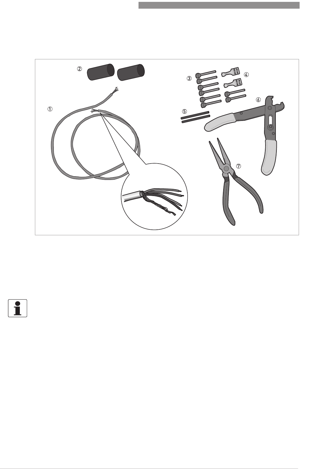
4.3.2 How to prepare a signal cable supplied by the customer
Figure 4-2: Equipment needed to prepare the signal cable
1 Signal cable (supplied on request)
2 2 heat-shrinkable sleeves for the PVC jacket (not supplied)
3 8 ferrules for the end of the conductors (not supplied)
4 2 Faston connectors for the shield wires
5 Shield wire insulation, 2 sleeves
6 Wire stripper (not supplied)
7 Crimping pliers (not supplied)
INFORMATION!
•
The Faston connector for the stranded drain wire must agree with DIN 46 228: E 1.5-8
•
The wire end ferrules for the twisted pair of conductors must agree with DIN 46 228: E 0.5-8
ELECTRICAL CONNECTIONS
4
45
OPTIWAVE 7400-24 C
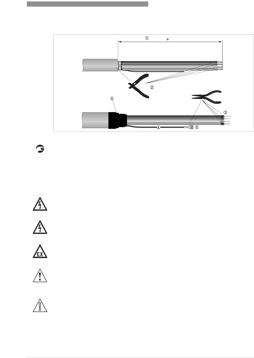
www.krohne.com12/2015 - 4003518001 - MA OPTIWAVE7400-24-R01-en
1 Remove the PVC jacket from the wire to dimension "a". a = 50 mm / 2¨.
2 Remove the insulation from the wire. Obey national regulations for electrical wiring.
3 Crimp the wire end ferrules on the conductors.
4 Install shield wire insulation on the 2 ends of the shield wire.
5 Crimp the Faston connectors on the 2 ends of the shield wire.
6 Install a heat-shrinkable sleeve on the PVC jacket.
4.3.3 How to connect the signal cable to the device
Figure 4-3: How to prepare the signal cable
DANGER!
Cables may only be connected when the power is switched off.
DANGER!
The device must be grounded in accordance with regulations in order to protect personnel
against electric shocks.
DANGER!
For devices used in hazardous areas, additional safety notes apply; please refer to the Ex
documentation.
WARNING!
Observe without fail the local occupational health and safety regulations. Any work done on the
electrical components of the measuring device may only be carried out by properly trained
specialists.
CAUTION!
Do not wind the signal cable. This configuration will prevent interference from electromagnetic
fields.
4
ELECTRICAL CONNECTIONS
46
OPTIWAVE 7400-24 C
www.krohne.com 12/2015 - 4003518001 - MA OPTIWAVE7400-24-R01-en
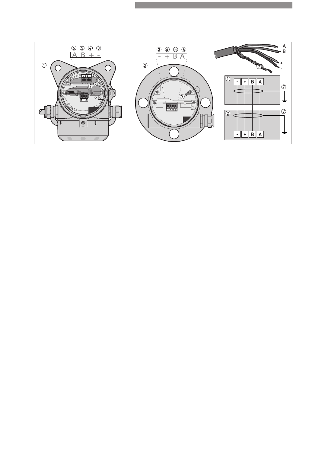
Figure 4-4:
1 Remote converter
2
3 Power supply: voltage in -
4 Power supply: voltage in +
5 Signal cable B
6 Signal cable A
7 )
ELECTRICAL CONNECTIONS
4
47
OPTIWAVE 7400-24 C
www.krohne.com12/2015 - 4003518001 - MA OPTIWAVE7400-24-R01-en
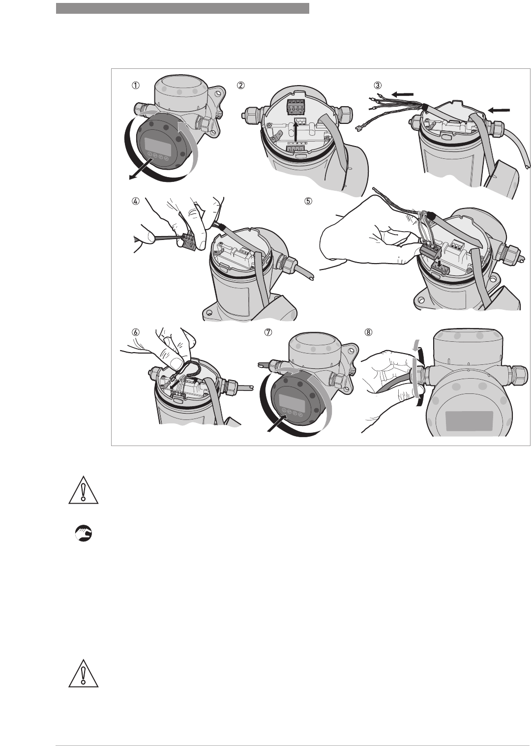
1 Remove the terminal compartment cover.
2 Remove the 4-pin connector.
3 Put the signal cable into the opening of the cable gland.
4 Put the electrical wires in the connector terminals. Tighten the terminal screws with a small
slotted-tip screwdriver. Make sure that the electrical wires agree with the terminals. For
more data, refer to the electrical schema in this section.
5 Put the connector into the 4-pin socket.
6 Attach the Faston connector (drain wire).
7 Attach the terminal compartment cover.
8 Tighten the cable gland. Make sure that the remote converter is correctly sealed.
How to connect the signal cable to the remote converter
Figure 4-5: How to connect the signal cable to the remote converter
CAUTION!
Bending radius of the signal cable: ≥50 mm / 2
¨
CAUTION!
Bending radius of the signal cable: ≥50 mm / 2
¨
4
ELECTRICAL CONNECTIONS
48
OPTIWAVE 7400-24 C
www.krohne.com 12/2015 - 4003518001 - MA OPTIWAVE7400-24-R01-en
1 Remove the terminal compartment cover.
2 Remove the 4-pin connector.
3 Put the signal cable into the opening of the cable gland.
4 Put the electrical wires in the connector terminals. Tighten the terminal screws with a small
slotted-tip screwdriver. Make sure that the electrical wires agree with the terminals. For
more data, refer to the electrical schema in this section.
5 Put the connector into the 4-pin socket. Attach the Faston connector (drain wire).
6 Attach the terminal compartment cover.
7 Tighten the cable gland. Make sure that the probe housing is correctly sealed.
4.4 Electrical connection for current output
4.4.1 Non-Ex devices
4.4.2 Devices for hazardous locations
4.5 Protection category
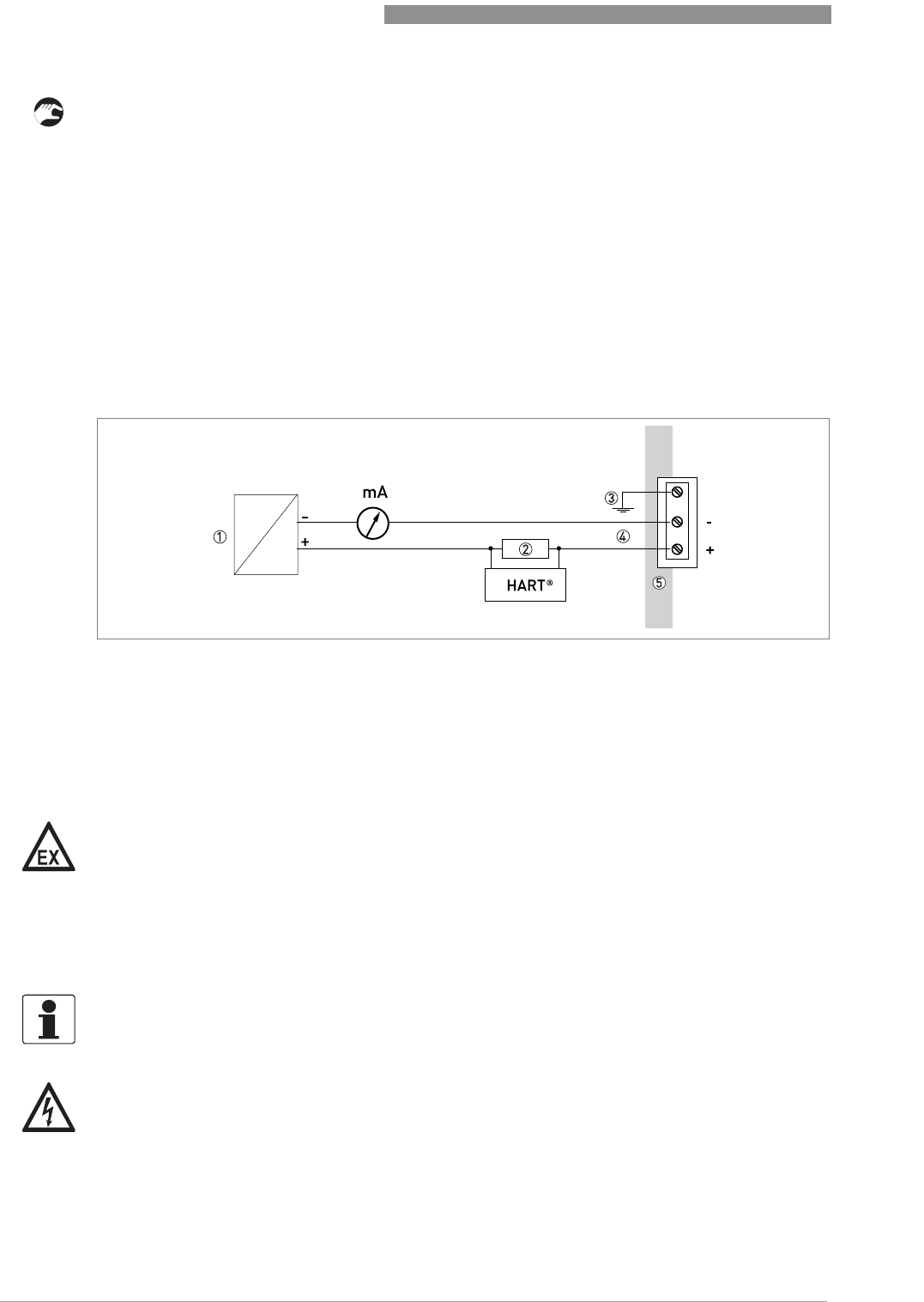
Figure 4-6: Electrical connections for non-Ex devices
1 Power supply
2 Resistor for HART® communication
3 Optional connection to the grounding terminal
4 Output: 11.5...30 VDC for an output of 22 mA at the terminal
5 Device
DANGER!
For electrical data for device operation in hazardous locations, refer to the related certificates of
compliance and supplementary instructions (ATEX, IECEx, cFMus, ...). You can find this
documentation on the DVD-ROM delivered with the device or it can be downloaded free of charge
from the website (Download Center).
INFORMATION!
The device fulfils all requirements per protection category IP66 / IP67. It also fulfils all
requirements per NEMA type 4X (housing) and type 6P .
DANGER!
Make sure that the cable gland is watertight.

ELECTRICAL CONNECTIONS
4
49
OPTIWAVE 7400-24 C
www.krohne.com12/2015 - 4003518001 - MA OPTIWAVE7400-24-R01-en
4.6 Networks
4.6.1 General information
The device uses the HART® communication protocol. This protocol agrees with the HART®
Communication Foundation standard. The device can be connected point-to-point. It can also
have a polling address of 1 to in a multi-drop network.
The device output is factory-set to communicate point-to-point. To change the communication
mode from point-to-point
point-to-pointpoint-to-point
point-to-point to multi-drop
multi-dropmulti-drop
multi-drop.
4.6.2 Point-to-point connection
Figure 4-7: Point-to-point connection (non-Ex)
1 Address of the device (0 for point-to-point connection)
2 4...20 mA + HART®
3 Resistor for HART® communication
4 Power supply
5 HART® converter
6 HART® communication software

4
ELECTRICAL CONNECTIONS
50
OPTIWAVE 7400-24 C
www.krohne.com 12/2015 - 4003518001 - MA OPTIWAVE7400-24-R01-en
4.6.3 Multi-drop networks
4.6.4 Fieldbus networks
For more data, refer to the supplementary instructions for FOUNDATION™ fieldbus and
PROFIBUS PA.
Figure 4-8: Multi-drop network (non-Ex)
1 Address of the device (each device must have a different address in multidrop networks)
2 4mA + HART®
3 Resistor for HART® communication
4 Power supply
5 HART® converter
6 HART® communication software
FOUNDATION™ fieldbus network (non-Ex)
Figure 4-9: FOUNDATION™ fieldbus network (non-Ex)
1 Field device
2 Junction box
3 H1 network
4 H1/HSE converter
5 High Speed Ethernet (HSE)
6 Workstation

ELECTRICAL CONNECTIONS
4
51
OPTIWAVE 7400-24 C
www.krohne.com12/2015 - 4003518001 - MA OPTIWAVE7400-24-R01-en
PROFIBUS PA/DP network (non-Ex)
Figure 4-10: PROFIBUS PA/DP network (non-Ex)
1 Field device
2 Bus termination
3 PROFIBUS PA bus segment
4 Segment coupler (PA/DP link)
5 PROFIBUS DP bus line
6 Control system (PLC / Class 1 master device)
7 Engineering or operator workstation (Control tool / Class 2 master device)
5
START-UP
52
OPTIWAVE 7400-24 C
www.krohne.com 12/2015 - 4003518001 - MA OPTIWAVE7400-24-R01-en
5.1 How to start the device
5.1.1 Start-up checklist
Check these points before you energize the device:
•Are all the wetted components (antenna, flange and gaskets) resistant to the product in the
tank?
•Does the information on the signal converter nameplate agree with the operating data?
•Did you correctly install the device on the tank?
•Do the electrical connections agree with the national electrical codes? Use the applicable
electrical cables with the cable glands.
5.1.2 How to start the device
• Connect the converter to the power supply.
• Energize the converter.
iDevices with the LCD display option only:
Devices with the LCD display option only:Devices with the LCD display option only:
Devices with the LCD display option only: After 10 seconds the screen will display "Starting
up". After 20 seconds the screen will display the software version numbers. After 30
seconds the default screen will appear.
• The device will display readings.
5.2 Operating concept
You can read measurements and configure the device with:
•A digital display screen (optional).
•A connection to a system or PC with PACTware™. You can download the Device Type
Manager (DTM) file from the website. It is also supplied on the DVD-ROM delivered with the
device.
•A connection to a system or PC with AMS™. You can download the Device Description (DD)
file from the website. It is also supplied on the DVD-ROM delivered with the device.
•A connection to a HART
®
Field Communicator. You can download the Device Description (DD)
file from the website. It is also supplied on the DVD-ROM delivered with the device.
DANGER!
Before you energize the device, make sure that the supply voltage and polarity are correct.
DANGER!
Make sure that the device and the installation agrees with the requirements of the Ex certificate
of compliance.
INFORMATION!
This chapter and the start of the chapter that follows tell you what data is given on the device
display in normal mode and how to change device settings in configuration mode. If you know
about how this device operates, you can ignore this data. Continue with the quick setup
procedure. For more data about this procedure, refer to Quick Setup (Commissioning) on page
70
.

START-UP
5
53
OPTIWAVE 7400-24 C
www.krohne.com12/2015 - 4003518001 - MA OPTIWAVE7400-24-R01-en
5.3 Digital display screen
5.3.1 Local display screen layout
The current output percentage is only shown if the measurement type (refer to item 2 in the
illustration) is the same as the output function. The parameter is set in menu item 2.4.1 (OUTPUT
FUNC.). For example, if the output function is set to "Level" and the device shows "Level"
measurements in normal mode, the bar graph and value is shown (refer to item 1 in the
illustration).
Figure 5-1: Local display screen layout in Normal mode
1 Current output percentage (bar graph and text — only shown if the current output function is the same as the mea-
surement on the screen in normal mode)
2 Measurement type (in this example, distance)
3 Device status (NE 107 symbols)
4 Device tag name
5 Updated measurement data symbol (the symbol flashes each time the measurement data is updated)
6 Measurement value and units
7 Device status (markers)
8 Keypad buttons (refer to the table in the section that follows)
5
START-UP
54
OPTIWAVE 7400-24 C
www.krohne.com 12/2015 - 4003518001 - MA OPTIWAVE7400-24-R01-en
5.3.2 Functions of keypad buttons
For data on keypad functions, refer to
Normal mode
on page 57.
5.4 Remote communication with PACTware™
PACTware™ displays measurement information clearly on a computer (PC) and lets you
configure the device from a remote location. It is an Open Source, open configuration software
for all field devices. It uses Field Device Tool (FDT) technology. FDT is a communication standard
for sending information between the system and the field device. Field devices are easily
integrated. Installation is supported by a user-friendly Wizard.
Install these software programs and equipment:
•Microsoft
®
.NET Framework version 1.1 or later.
Figure 5-2: Local display screen layout in configuration mode
1 Function name
2 Configuration mode symbol
3 Menu number
Keypad button Function
[Right] Normal mode:
Normal mode:Normal mode:
Normal mode: Enter menu (Enter Configuration mode)
Configuration mode:
Configuration mode:Configuration mode:
Configuration mode: Move cursor to the right
[Return / Escape] Normal mode:
Normal mode:Normal mode:
Normal mode: Change units (m, cm, mm, in, ft)
Configuration mode:
Configuration mode:Configuration mode:
Configuration mode: Exit
[Down] Normal mode:
Normal mode:Normal mode:
Normal mode: Change measurement type (distance, level , output (%),
output (mA), conversion, ullage conversion) 1
Configuration mode:
Configuration mode:Configuration mode:
Configuration mode: Decrease value or change parameter
[Up] Normal mode:
Normal mode:Normal mode:
Normal mode: Change measurement type (distance, level , output (%),
output (mA), conversion, ullage conversion, reflection) 1
Configuration mode:
Configuration mode:Configuration mode:
Configuration mode: Increase value or change parameter
1If you have made a strapping table in menu item 2.8.1 INPUT TABLE for volume or mass measurement, "Conversion"
and "Ullage Conv." will be shown in the list of measurement types

START-UP
5
55
OPTIWAVE 7400-24 C
www.krohne.com12/2015 - 4003518001 - MA OPTIWAVE7400-24-R01-en
•PACTware.
•HART
®
converter (USB, RS232...).
•The Device Type Manager for the device.
The software and installation instructions are given on the DVD-ROM supplied with the device.
You can also download the latest version of PACTware™ and the DTM from our internet site.
Refer also to the PACTware™ consortium site at http://www.pactware.com.
5.5 Remote communication with the AMS™ Device Manager
The AMS™ Device Manager is an industrial Plant Asset Management (PAM) software tool. Its
role is to:
•Store configuration information for each device.
•Support HART® and FOUNDATION™ fieldbus devices.
•Store and read process data.
•Store and read diagnostic status information.
•Help plan preventive maintenance to reduce a plant's downtime to a minimum.
The DD file is given on the DVD-ROM supplied with the device. You can also download it from our
website.
Figure 5-3: Screen from the PACTware™ user interface
1 DTM menu
2 Information for device identification
3 Configuration summary

6
OPERATION
56
OPTIWAVE 7400-24 C
www.krohne.com 12/2015 - 4003518001 - MA OPTIWAVE7400-24-R01-en
6.1 User modes
Normal mode
Normal modeNormal mode
Normal mode This mode displays measurement data. For more data, refer to
Normal
mode
on page 57.
Configuration mode
Configuration modeConfiguration mode
Configuration mode Use this mode to view parameters, commission the device, create tables
for volume or mass measurement, change critical values to measure in
difficult process conditions. To get access to supervisor menu, refer to
Protection of the device settings
on page 73. For more data on menu items,
refer to
Function description
on page 63.

OPERATION
6
57
OPTIWAVE 7400-24 C
www.krohne.com12/2015 - 4003518001 - MA OPTIWAVE7400-24-R01-en
6.2 Normal mode
This mode shows measurement data. Use the table that follows:
•for the selection of the measurement type (level, distance, percentage, conversion and
reflection) and
•for the selection of the measurement units
Some measurement types will only be available if the device has the correct parameters entered
in the configuration mode.
Measurement type definitions
Measurement type Description Available units
LEVEL This is a display and an output function option.
It is the height from the bottom of the tank to
the surface of the liquid (Tank height -
Distance).
m, cm, mm, in (inches), ft
(feet)
DISTANCE This is a display and an output function option.
It is the distance from the face of the flange (or
thread stop) to the surface of the liquid.
m, cm, mm, in (inches), ft
(feet)
CONVERSION This is a display and an output function option.
It gives the volume or mass of the tank
contents. This data is available if you prepare a
volume or mass table in configuration mode.
For data on how to prepare the conversion
table, refer to
How to configure the device to
measure volume or mass
on page 76. If the
device is used with PACTware™ software, it
can also show flow rate in a channel. 6 flow
profiles are available in the menu: Parshall
(ISO 9826), Venturi Rectangular (ISO 4359),
Venturi Trapezoidal (ISO 4359), Venturi U
(ISO 4359), V-Notch (ISO 1438) or Rectangular
Notch (ISO 1438).
m3, L, gal (US gallons), ImpG
(Imperial gallons), ft3, bbl (oil
barrel), kg, t, Ston, Lton, m,
cm, mm, in, ft, m3/h, ft3/h
ULLAGE CONV. This is a display and an output function option.
It gives the empty volume or remaining mass
that can be put in the tank. This data is
available if you prepare a volume or mass table
in configuration mode. For data on how to
prepare the conversion table, refer to
How to
configure the device to measure volume or
mass
on page 76.
m3, L, gal (US gallons), ImpG
(Imperial gallons), ft3, bbl (oil
barrel), kg, t, Ston, Lton, m,
cm, mm, in, ft, m3/h, ft3/h
REFLECTION This is a display and an output function option.
It is the percentage of the emitted radar signal
which makes a reflection on the surface of the
liquid and is received by the device.
%
OUTPUT I (mA) The current output of the device. mA
OUTPUT I (%) The percentage of the current output.
0% = 4 mA. 100% = 20 mA. %
6
OPERATION
58
OPTIWAVE 7400-24 C
www.krohne.com 12/2015 - 4003518001 - MA OPTIWAVE7400-24-R01-en
6.3 Configuration mode
6.3.1 General notes
Change the settings of your device in Configuration
ConfigurationConfiguration
Configuration mode. Data about the menus is given on page
63. You can:
•Use the 1.0.0 INFORMATION
1.0.0 INFORMATION1.0.0 INFORMATION
1.0.0 INFORMATION menu to read settings, device software versions and error
records. For more data about the Information menu, refer to Table 1: Info.
•Use the 2.0.0 SUPERVISOR
2.0.0 SUPERVISOR2.0.0 SUPERVISOR
2.0.0 SUPERVISOR menu to commission the device, to run diagnostic tests, set up a
conversion table for volume, mass or flow rate measurement, change critical parameters for
difficult process conditions, reset the device and change basic parameters (tank height etc.),
output settings, HART Address etc. For more data about the Supervisor menu, refer to Table
2: Supervisor.
6.3.2 How to get access to the commissioning menu
The Quick Setup menu contains the menu items that are necessary for most configurations of
the device. The menu items are divided into 2 groups: "Commisioning" and "Recording Empty
Spectrum". The "Commisioning" group lets the supervisor set the tank height, tank type
(process, storage etc.), output function, output current range, 4 mA output setting, 20 mA output
setting, error delay and tag name. "Recording Empty Spectrum" is a procedure that finds
interference signals in the tank and uses a filter to remove them from the measurement data.
Do the steps that follow:
• Push the [>
>>
>] button.
iThis shows the Information
InformationInformation
Information menu. The Information
InformationInformation
Information menu is read only and does not have
password security.
• Push the [
] button one time to scroll up to the Supervisor
SupervisorSupervisor
Supervisor menu.
iThe screen shows the text "2.0.0 SUPERVISOR".
• Push the [>
>>
>] button one time.
iThe screen shows a line. You must enter the password. Push the buttons under the display
screen 6 times (in total and in a given order) to get access to Configuration mode.
• Type in the password. The factory-set password is [>
>>
>], [^
^^
^], [
], [
], [>
>>
>] and [^
^^
^].
iThe device shows the text "2.1.0 QUICK SETUP".
CAUTION!
The quick setup (commissioning) procedure is mandatory.
INFORMATION!
It is not possible to enter the 3.0.0 SERVICE and 4.0.0 MASTER menus. These menus are for
factory calibration and approved personnel only.
INFORMATION!
HOW TO SET THE SUPERVISOR PASSWORD TO "ON" OR "OFF"
The supervisor password is set to "on" by default. If it is necessary to set this function to "off",
refer to Function description on page 63
, Table 2: Supervisor menu, menu item PSWD YES/NO
(2.7.4).
OPERATION
6
59
OPTIWAVE 7400-24 C
www.krohne.com12/2015 - 4003518001 - MA OPTIWAVE7400-24-R01-en
6.3.3 Keypad functions
This is what you see when you are in Configuration mode. The functions of the buttons are given
in the table that follows:
Functions of buttons for menu navigation
INFORMATION!
HOW TO CHANGE THE SUPERVISOR PASSWORD
You can change the password for the supervisor menu. For more data, refer to Function
description on page 63
, Table 2: Supervisor menu, menu item PASSWORD (2.7.5).
Figure 6-1: Local display screen layout in configuration mode
1 Function name
2 Configuration mode symbol
3 Menu number
Button Description Function
Right
•
Go down to the sub-menu level (for example, from menu 1.0.0 to
sub-menu 1.1.0).
•
Enter the menu item
Enter /
Esc (Escape)
•
Go up to the menu level (for example, from sub-menu 1.1.0 to menu
1.0.0).
•
Go to Normal mode. If you changed settings in Configuration mode,
you must save or cancel your new settings. For more data, refer to
the end of this section.
Down
•
Scroll down the menu list (for example, from menu 2.0.0 to menu
1.0.0).
•
Scroll down the sub-menu list (for example, from sub-menu 2.2.0 to
sub-menu 2.1.0).
Up
•
Scroll up the menu list (for example, from menu 1.0.0 to menu
2.0.0).
•
Scroll up the sub-menu list (for example, from sub-menu 2.1.0 to
sub-menu 2.2.0).
6
OPERATION
60
OPTIWAVE 7400-24 C
www.krohne.com 12/2015 - 4003518001 - MA OPTIWAVE7400-24-R01-en
This is what you see when you select a menu item that has a list of parameters. The functions of
the buttons are given in the table that follows:
Function of buttons in menu items that have a list of parameters
Lists of parameters in menu items
Figure 6-2: Lists of parameters in menu items
1 Parameter
2 Menu name
Button Description Function
Right n/a
Enter /
Esc (Escape) Select the parameter and go back to the menu
Down Move down the list
Up Move up the list
OPERATION
6
61
OPTIWAVE 7400-24 C
www.krohne.com12/2015 - 4003518001 - MA OPTIWAVE7400-24-R01-en
This is what you see when you select a menu item that has a value. The functions of the buttons
are given in the table that follows:
Function of buttons in menu items that have values
How to save settings changed in the supervisor menu (menu 2.0.0)
• When you have changed parameters in all the necessary menu items, push [^
^^
^] to accept the
new parameter.
• Push [^
^^
^] to go back to the "STORE" screen.
• The device will ask you to save or cancel your settings. Push [
] or [
] to select STORE YES
STORE YESSTORE YES
STORE YES or
STORE NO
STORE NOSTORE NO
STORE NO. Push [^
^^
^] to accept or reject the new settings.
iThe display goes back to Normal mode.
Values in menu items
Figure 6-3: Values in menu items
1 Menu item with values stored at this time (first screen)
2 Push [>
>>
>] again to change the values. A cursor shows on the first digit.
3 Menu item name
4 Cursor on the selected digit
Button Description Function
Right
•
Enter the menu item and see the value stored at this time.
•
Enter the menu item configuration level to change the value.
•
Move the cursor to the next digit on the right. If the cursor is on the
last digit, push [>
>>
>] again to go back to the first digit.
Enter /
Esc (Escape) Accept the value and go back to the sub-menu.
Down Decrease the digit value.
Up Increase the digit value.
6
OPERATION
62
OPTIWAVE 7400-24 C
www.krohne.com 12/2015 - 4003518001 - MA OPTIWAVE7400-24-R01-en
6.3.4 Menu overview
1.0.0 Info. (Information)
1.1.0 Ident. (Identification)
1.2.0 Output
1.3.0 History
2.0.0 Supervisor
2.1.0 Quick Setup
2.2.0 Tests
2.3.0 Basic Parameters
2.4.0 Output I
2.5.0 Application
2.6.0 Communication
2.7.0 Display
2.8.0 Conversion
2.9.0 Config/Reset
3.0.0 Service
n/a Password locked. Menus for factory calibration and qualified
service personnel only.
4.0.0 Master
n/a Password locked. Menus for factory calibration and qualified
service personnel only.

OPERATION
6
63
OPTIWAVE 7400-24 C
www.krohne.com12/2015 - 4003518001 - MA OPTIWAVE7400-24-R01-en
6.3.5 Function description
1.0.0 Information (Info.) menu
Menu
No.
Function Function description Selection list Default
1.1.0 IDENT.
1.1.1 SERIAL NUM. The device serial number. Read only.
1.1.2 CONV.FIRM.VER The converter firmware version. Read only.
1.1.3 SEN.FIRM.VER The sensor firmware version. Read only.
1.1.4 HMI.FIRM.VER The HMI (device display screen)
firmware version. Read only.
1.1.5 The converter hardware version. Read only.
1.1.5 The sensor hardware version. Read only.
1.1.8 The HMI (device display screen)
hardware version. Read only.
1.1.9 The date of manufacture. Read only.
1.2.0 OUTPUT
1.2.1 OUTPUT FUNC. This shows the setting at this time for
the output function (OUTPUT FUNC.). Read only.
1.2.2 RANGE I This shows the setting at this time for
the output range (RANGE I). Read only.
1.2.3 SCALE 4mA This shows the setting at this time for
the 4 mA setting (SCALE 4mA). Read only.
1.2.4 SCALE 20mA This shows the setting at this time for
the 20 mA setting (SCALE 20mA). Read only.
1.2.5 ERROR DELAY This shows the settings at this time for
the error delay (ERROR DELAY). Read only.
1.3.0 HISTORY
1.3.1 ERROR RECORD A log of device errors. Push [>
>>
>] to read
the errors. Push [
] or [
] to scroll up
or down the list. Each error is identified
by a code. Push [>
>>
>] again to show the
number of incidents and the time since
the last incident in days, hours,
minutes and seconds. For more data
about errors, refer to
Status and error
messages
on page 79.
Read only.
1.3.2 A log of the last 10 changes to the
device settings. Push [
] or [
] to
scroll up or down the list. Push [>
>>
>] to
show the time since the last change in
days, hours, minutes and seconds.
Read only.

6
OPERATION
64
OPTIWAVE 7400-24 C
www.krohne.com 12/2015 - 4003518001 - MA OPTIWAVE7400-24-R01-en
2.0.0 Supervisor menu
Menu
No.
Function Function description Selection list Default
2.1.0 COMMISSION.
2.1.1 PARAMETERS This starts a quick set-up procedure
applicable to most applications. The
supervisor can give the display language
(LANGUAGE), tank height (TANK HEIGHT),
type of tank (TANK TYPE), output function
(OUTPUT FUNC.), current output range
(RANGE I), 4 mA setting (SCALE 4mA),
20 mA setting (SCALE 20mA), error delay
(ERROR DELAY) and tag name (TAG NAME).
2.1.2 EMP.SPEC.REC. Fixed and moving objects in the tank cause
interference signals. Put them through this
filter to correctly measure the tank
contents. A quick set-up procedure will go
through the steps that follow (refer also to
"How to make a filter to remove radar signal
interference" on page 77):
1Do you have a completely filled tank?
Do you have a completely filled tank?Do you have a completely filled tank?
Do you have a completely filled tank?
If the tank is full, it is not possible to
complete this procedure. The tank must be
partially filled or empty.
Yes [>
>>
>], No [
]
2Please, activate moving parts!
Please, activate moving parts!Please, activate moving parts!
Please, activate moving parts!
We recommend that you switch on moving
equipment to filter all interference signals.
OK [>
>>
>]
3Is your tank partially filled or empty?
Is your tank partially filled or empty?Is your tank partially filled or empty?
Is your tank partially filled or empty?
If the tank is partially filled, the device must
include the tank contents when it filters the
signal.
Partially [>
>>
>], Empty [
]
4MEAS.DISTANCE
MEAS.DISTANCEMEAS.DISTANCE
MEAS.DISTANCE
If the tank is partially filled, type in a
distance shorter than that between the
flange and the tank contents.
min-max: 0…tank height
(2.3.1) distance to
tank contents -
300 mm / 12¨
5Emp.Spec.Type
Emp.Spec.TypeEmp.Spec.Type
Emp.Spec.Type
Use the average value for tanks which
contain fixed objects only. Use the
maximum value for tanks which contain
many objects or moving objects.
Maximum, Average ?
6Recording in progress
Recording in progressRecording in progress
Recording in progress
Reading in progress
Reading in progressReading in progress
Reading in progress
7Empty spectrum graph
Empty spectrum graphEmpty spectrum graph
Empty spectrum graph
This shows a set of spectra (signals found in
the tank). It also gives the amplitude and
location of each signal. Push [>
>>
>] to make a
selection from the available spectra.
8Do you want to save the empty spectrum
data? Yes [>
>>
>], No [
]
2.2.0 TESTS
2.2.1 SET OUTPUT This sets the current output to a test value
[mA]. The output will change to the given
value, independent of the measured value.
The current output will go back to the
measured value when the display goes back
to the menu level.
3.5, 4, 6, 8, 10, 12, 14, 16,
18, 20 or 22 mA 3.5 mA

OPERATION
6
65
OPTIWAVE 7400-24 C
www.krohne.com12/2015 - 4003518001 - MA OPTIWAVE7400-24-R01-en
2.2.2 DIAGNOSTIC This starts the hardware test. Push [>
>>
>] many
times to show:
•
D1, the time of operation
•
T1, temperature of the electronic
converter board
•
I1, loop current (internally measured
value)
•
I2, load current (NOTE: this data is not
available at this time)
•
V1, voltage 5.6 V. If the voltage is not
5.0<V1<5.7, speak to the supplier.
•
V2, voltage on capacitors. If the voltage is
not 3.2<V2<3.4, speak to the supplier.
•
V3, voltage 3.3 V. If the voltage is not
3.2<V3<3.4, speak to the supplier.
•
C1, reset counter (watchdog timer). If
C1>1, replace the signal converter.
If an NE 107 symbol and a status marker are
shown, refer to
Device status (markers)
on
page 79.
If you push [>
>>
>] again, the display goes back
to the menu level.
2.2.3. The corrected spectrum. TBD.
2.3.0 BASIC PARAM.
2.3.1 TANK HEIGHT The distance from the flange face / thread
stop of the tank connection down to the tank
bottom. If the tank has a dish-shaped or
conical bottom, the tank height is measured
to a point on the tank bottom directly below
the antenna. For more data about level
measurement, refer to
Level measurement
on page 75. For more data about distance
measurement, refer to
Distance
measurement
on page 74.
min-max: 0…30 m /
0…98.4 ft
1
2.3.2 BLOCK. DIST. Blocking distance. The distance from the
flange to the top limit of the measuring
range (a zone given by the user where it is
not possible to measure). We recommend a
blocking distance of 500 mm / 19.7¨ below
the process connection. We also
recommend that the limit of the measuring
range is not less than the blocking distance.
If it is possible that the tank contents will go
above the blocking distance, set 2.5.5
OVERF. ENAB. to "Yes". If the distance is
less than the blocking distance, the device
continues to display the blocking distance.
min: 100 mm / 13.9¨ or
2.3.6 ANTENNA.EXT
max: 2.3.1 TANK HEIGHT
500 mm / 19.7¨
2.3.3 TIME CONST. Using this function, the device processes
several measurement readings to filter out
disturbances. Increasing the time constant
will smoothen the integrated readings,
decreasing will roughen the readings.
s=seconds.
min-max: 1.00...100.00 s 5.00 s
2.3.4 TAG NAME The device has an identification code (tag
name). The supervisor can enter a
maximum of 8 numbers or letters.
1
2.3.5 ANTENNA.EXT Optional antenna extensions.These are
attached between the flange and the
antenna.
min: 0 mm / 0¨ or 2.3.6
ANTENNA.EXT
max: 2000 mm / 78.7¨ or
2.3.1 TANK HEIGHT
1
Menu
No.
Function Function description Selection list Default

6
OPERATION
66
OPTIWAVE 7400-24 C
www.krohne.com 12/2015 - 4003518001 - MA OPTIWAVE7400-24-R01-en
2.3.6 DIST.PIECE Optional distance piece between the
converter and the process connection. This
is for high-temperature applications more
than +150°C / +302°F. The distance piece is
120 mm / 4.7¨ long. For more data, refer to
Technical data
on page 90.
min: 0 mm / 0¨
max: TANK HEIGHT
1
2.3.7 Reference offset. Offset relating to a
reference location (distance). This value is
positive when the reference location is
above the device flange face and negative if
below. For more data, refer to
Distance
measurement
on page 74.
min-max:
-tank height…50 m /
-tank height...164.05 ft
0m/ 0ft
2.3.8 Tank bottom offset. Offset relating to a
reference location (level). The device
reference point for this parameter is the
bottom of the tank (set in menu item
C.1.2.0). This value is positive when the
reference location is below the tank bottom
and negative if above. For more data, refer
to
Level measurement
on page 75.
min-max:
-tank height...3000 m /
-tank height...9843 ft
0m/ 0ft
2.4.0 OUTPUT I
2.4.1 OUTPUT FUNC. The output function. Select an output
function to scale the current values in
relation to a given point (usually the device
process connection or the tank bottom). The
output current value is shown on a bar
graph in normal mode if the measurement
type is the same as the output function.
Conversion parameters are shown
(Conversion, Ullage conversion) if there is
level-volume, level-mass or level-flow rate
data in 2.8.1 INPUT TABLE.
Distance, Level,
Conversion, Ullage
conversion, Reflection
1
2.4.2 RANGE I This menu item sets the limits of the output
current range to 1 of the 2 available options:
standard limits (4...20 mA) or NAMUR
NE 43-compliant limits (3.8...20.5 mA). It
also tells the device what to do if an error
occurs. if you set RANGE I to 4-20/22E
4-20/22E4-20/22E
4-20/22E and
an error occurs (e.g. the tank is too full, ...),
the device output current will change to an
error value of 22 mA . If you set RANGE I to
4-20
4-204-20
4-20 and the device senses a measurement
error, the value will stop at the last correct
measurement.
4-20, 4-20/22E, 4-
20/3.6E, 3.8-20.5/22E,
3.8-20.5/3.6E
4-20/3.6E
2.4.3 SCALE 4mA This gives a measurement value to 4 mA. min.-max: 2 1
2.4.4 SCALE 20mA This gives a measurement value to 20 mA. min.-max: 2 1
2.4.5 ERROR DELAY The time after which the current output
changes to an error value. The error value
shows that there is a measurement error.
mn=minutes and s=seconds.
0 s, 10 s, 20 s, 30 s, 1 mn,
2 mn, 5 mn,15 mn 0s
2.5.0 APPLICATION
2.5.1 TANK TYPE The conditions in which the device is used. If
the surface of the product is flat, select
"Storage". If the surface of the product is
disturbed, select "Process". If the surface of
the product is agitated with vortexes and
foam, select "Agitator".
Storage, Process,
Agitator Process
Menu
No.
Function Function description Selection list Default

OPERATION
6
67
OPTIWAVE 7400-24 C
www.krohne.com12/2015 - 4003518001 - MA OPTIWAVE7400-24-R01-en
2.5.2 STILLWELL D. The inner diameter of the stilling well. If the
device is installed in a stilling well or has a
Wave-Guide antenna, enter the diameter.
The device will use this data if you set 2.3.4
STILLWELL EN. to "Yes". This menu item is
not shown if you set 2.3.4 STILLWELL EN. to
"No".
min-max: 22...999 mm /
0.9...39.3¨
1
2.5.3 TRACING VEL. Maximum tracking velocity. This value must
agree with the maximum rate of change of
the level of the liquid in the tank.
min-max:
0.1…10.0 m/min 0.5 m/min
2.5.4 MEASUR.MODE The device uses the dielectric constant (ε
r
)
of the tank contents to monitor level. In
direct mode (if the dielectric constant is
high), the level signal is a reflection on the
surface of the tank contents. If the dielectric
constant is low, the device uses TBF mode.
The device in TBF mode uses the radar
reflection on the bottom of the tank (the
signal goes through the tank contents). The
tank must have a flat bottom for the device
to operate correctly in TBF mode. This
menu item is set by default to "Direct" for
tank contents with an ε
r
>1.8. If ε
r
is very low
(<1.6), use "TBF Full". If ε
r
is low (ε
r
=
1.5...1.7), use "TBF Partial" mode. "TBF
Partial" is an automatic mode that lets the
device make a selection between "Direct
mode and "TBF" mode. If you use "TBF Full"
or "TBF Partial", enter the dielectric
constant in menu item 2.5.3 Er PRODUCT.
Refer also to "Measuring principle" on page
90.
Direct, TBF Partial, TBF
Full Direct
2.5.5 Er PRODUCT For measurement in TBF mode only. The
device automatically calculates the level
based on the product ε
r
. If you select "TBF
Partial" or "TBF Full" in menu item 2.5.4
MEASUR.MODE, you can change the ε
r
value
manually to adjust readings.
min-max: 1.100 to 10.000 2.000
2.5.6 OVERF. ENAB. If this function is in operation, the device will
monitor the level even if it is in the blocking
distance. The reading shown on the display
stays fixed at the blocking distance if the
level is higher than the blocking distance.
The output will show that the tank is full. An
error is recorded by default.
If this function is not in operation, the
device looks for the largest signal between
the process connection and the tank bottom.
YES, NO NO
2.5.7 OVERF.
THRESH. The overfill threshold. TBD.
Menu
No.
Function Function description Selection list Default

6
OPERATION
68
OPTIWAVE 7400-24 C
www.krohne.com 12/2015 - 4003518001 - MA OPTIWAVE7400-24-R01-en
2.5.8 MULT.REF.EN. Multiple reflections will cause the device to
display smaller level readings. Objects in
the tank, sharp corners, installation of the
device on a large nozzle or at the centre of a
dome roof, and low dielectric products (ε
r
=
1.8...5) can cause multiple reflections. A
very calm surface or a tank with a small
convex or flat roof can also cause multiple
reflections.
If this function is in operation, the device
looks for the first signal peak below the
process connection. This signal peak is then
used to measure the level of the tank
contents. If this function is not in operation,
the device looks for the largest signal below
the process connection.
YES, NO NO
2.5.7 EMP.SPEC.EN. The supervisor can start or stop the empty
spectrum filter. YES, NO NO
2.6.0 COMMUNICAT.
2.6.1 ADDRESS Any HART
®
address greater than 0 will
activate HART
®
multidrop mode. The
current output stays constant at 4 mA.
min.-max: 0…63 0
2.6.2 Each HART value (PV (primary value), SV
(secondary value), TV (tertiary value) and QV
(quaternary value)) can be set to a different
measurement type (level, distance,
reflectivity, conversion, ullage conversion).
2.7.0 DISPLAY
2.7.1 LANGUAGE Data can be shown in any of the languages
stored in the device. 9 languages are available
in 3 packs: (1) English,
French, German and
Italian; (2) English,
French, Spanish and
Portuguese; (3) English,
Chinese (Mandarin),
Japanese and Russian
3
2.7.2 LENGTH UNIT The length unit shown in normal mode. m, cm, mm, in (inches), ft
(feet) m
2.7.3 CONV UNIT Conversion unit. The length, volume, mass
or flow rate conversion unit for the
conversion table and shown in normal
mode.
m3, L, gal (US gallons),
ImpG (Imperial gallons),
ft3, bbl (oil barrel), kg, t,
Ston, Lton, m, cm, mm,
in, ft, m3/h, ft3/h
L
2.7.4 PSWD YES/NO If it is necessary to protect your settings in
the supervisor menu with a password, set
this menu item to YES
YESYES
YES.
YES, NO YES
2.7.5 PASSWORD This changes the password for the
supervisor menu. Push the buttons up to 6
times in any order. This will be the new
password. To confirm the change, enter the
new password a second time. For more
data, refer to
Protection of the device
settings
on page 73.
[>
>>
>], [^
^^
^], [
],
[
], [>
>>
>] and [^
^^
^]
2.7.6 CONTRAST The contrast control for the display screen.
You can select a shade of grey between light
grey (level 20) and black (level 54).
min.-max: 20…54 36
Menu
No.
Function Function description Selection list Default

OPERATION
6
69
OPTIWAVE 7400-24 C
www.krohne.com12/2015 - 4003518001 - MA OPTIWAVE7400-24-R01-en
3. Service menu
4. Master menu
2.7.7 If it is not easy to read the data on the LCD
display screen, this menu item operates the
display screen light. If you set this menu
item to YES
YESYES
YES, the light comes on.
YES, NO NO
2.8.0 CONV. TABLE
2.8.1 INPUT TABLE The device uses a conversion table
(strapping table) to convert measurements
to volume, mass and flow rate readings. The
readings are shown in normal mode. Give
the number of entries on the table (min. 2;
max. 30). Select an entry (01...30) and enter
the level and the related volume / mass /
flow rate value for that entry. Push [^
^^
^] to
confirm the entry values. Continue the
procedure until the device has data for all
the entries. For more data, refer to
How to
configure the device to measure volume or
mass
on page 76.
min. 2 entries
max. 30 entries
(level / volume, mass or
flow rate)
0 entries
2.8.2 DELETE TABLE This menu item erases the data in the
conversion table. YES, NO NO
2.9.0 CONFIG/RESET
2.9.1 SAVE This menu item is not available. YES, NO NO
2.9.2 RECALL This menu item is not available. YES, NO NO
2.9.3 RESTART This menu item starts the device again. YES, NO NO
2.9.4 RESET FACT. If you set this menu item to "YES", the
device goes back to its initial settings (set by
the manufacturer in the factory).
YES, NO NO
1This value is given in the customer order data
2Units and range depend on the output function, length unit and volume unit selected
3If the device has the LCD display option, this depends on data given in the customer order
Menu
No.
Function Function description Selection list Default
3.0.0 SERVICE Advanced settings. The settings in this
menu are protected with a password.
Only approved personnel can change
the parameters in this menu. For more
data, speak or write to your local sales
office.
Menu
No.
Function Function description Selection list Default
4.0.0 MASTER Factory settings. The settings in this
menu are protected with a password.
Only approved personnel can change
the parameters in this menu. For more
data, speak or write to your local sales
office.
Menu
No.
Function Function description Selection list Default
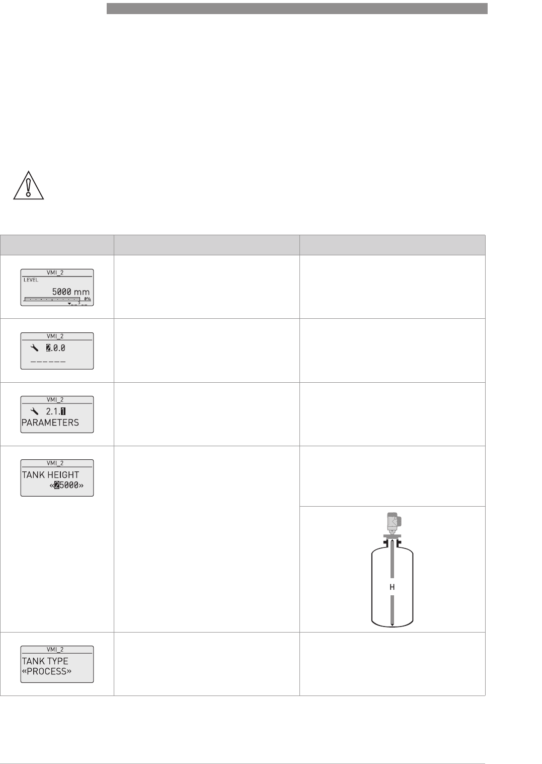
6
OPERATION
70
OPTIWAVE 7400-24 C
www.krohne.com 12/2015 - 4003518001 - MA OPTIWAVE7400-24-R01-en
6.4 Further information on device configuration
6.4.1 Quick Setup (Commissioning)
Use this procedure to change the tank height, tank type, output function, output range and give
the top and bottom measuring limits. Values and parameters that can be changed are shown
between the «... » marks in the illustrations that follow. Push the keypad buttons in the correct
sequence:
Procedure
CAUTION!
Make sure that you do this procedure before you use the device. The settings in this procedure
have an effect on the performance of the device.
Screen Steps Description
•
[>
>>
>], [
] and [>
>>
>]. Default screen.
Enter configuration mode (2.0.0
SUPERVISOR).
•
[>
>>
>], [^
^^
^], [
], [
], [>
>>
>] and [^
^^
^]. Enter the password (the default password is
shown). If it is necessary to change the
password, menu item 2.7.5 PASSWORD.
•
2× [>
>>
>] Push this button to start the quick set-up
procedure.
•
[>
>>
>] to change the tank height (H).
•
[>
>>
>] to change the position of the cursor.
•
[
] to decrease the value or [
] to
increase the value.
•
[^
^^
^] to confirm.
The distance from the flange face / thread
stop of the tank connection down to the tank
bottom. If the tank has a dish-shaped or
conical bottom, the tank height is measured
to a point on the tank bottom directly below
the antenna.
•
[
] or [
] for the selection of the
conditions in which the device is used
(Storage, Process, Agitator).
•
[^
^^
^] to confirm.
If the surface of the product is flat, select
"Storage". If the surface of the product is
disturbed, select "Process". If the surface of
the product is agitated with vortexes and
foam, select "Agitator".
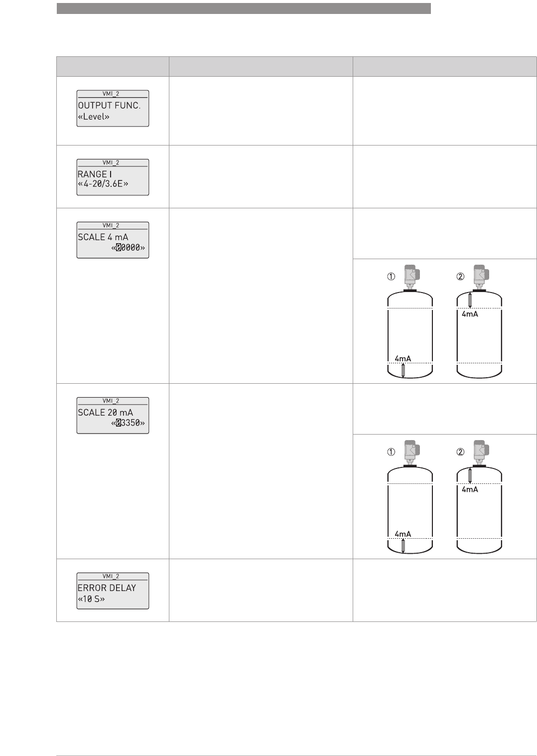
OPERATION
6
71
OPTIWAVE 7400-24 C
www.krohne.com12/2015 - 4003518001 - MA OPTIWAVE7400-24-R01-en
•
[
] or [
] for the selection of the
measurement name (Distance, Level,
Conversion, Ullage Conv. or Reflection).
•
[^
^^
^] to confirm.
The manufacturer sets the output function
to “Level” before delivery.
If it is necessary to measure volume, ullage
volume, mass or ullage mass (Conversion
or Ullage Conv.), refer to
How to configure
the device to measure volume or mass
on
page 76.
•
[
] or [
] for the selection of the current
output range (4-20 mA/3.6E, 4-20, 3.8-
20.5/3.6E, etc.).
•
[^
^^
^] to confirm.
•
[>
>>
>] to change Scale 4 mA.
•
[>
>>
>] to change the position of the cursor.
•
[
] to decrease the value or [
] to
increase the value.
•
[^
^^
^] to confirm.
Use this step to give the 4 mA output setting
(0% limit) in the tank. Refer to the
illustrations that follow. Illustration 1
shows the settings for level. Illustration 2
shows the settings for distance.
•
[>
>>
>] to change Scale 20 mA.
•
[>
>>
>] to change the position of the cursor.
•
[
] to decrease the value or [
] to
increase the value.
•
[^
^^
^] to confirm.
Use this step to give the 20 mA output
setting (100% limit) in the tank. Refer to the
illustrations that follow. Illustration 1
shows the settings for level. Illustration 2
shows the settings for distance.
•
[
] or [
] for the selection of the error
delay (0 s, 10 s, 20 s, 30 s, 1 mn, 2 mn,
5 mn or 15 mn).
•
[^
^^
^] to confirm.
The time after which the current output
changes to an error value. The error value
shows that there is a measurement error.
Screen Steps Description
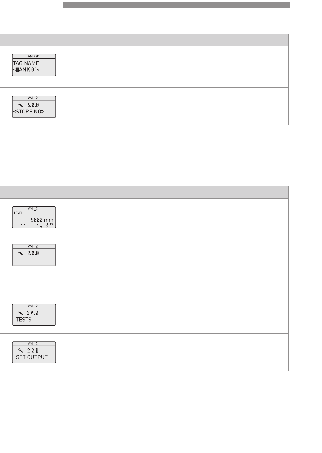
6
OPERATION
72
OPTIWAVE 7400-24 C
www.krohne.com 12/2015 - 4003518001 - MA OPTIWAVE7400-24-R01-en
6.4.2 Test
Use this procedure to test the loop current. Values and parameters that can be changed are
shown between the «... » marks in the illustrations that follow. Push the keypad buttons in the
correct sequence:
Procedure
•
[>
>>
>] to change the tag name.
•
[>
>>
>] to change the position of the cursor.
•
[
] to decrease the alphanumeric value
(A, B, ..., 1, 2, ...) or [
] to increase the
alphanumeric value.
•
[^
^^
^] to confirm.
The device has an identification code (tag
name). The supervisor can enter a
maximum of 8 numbers or letters.
•
2× [^
^^
^] to confirm.
•
[
] or [
] for the selection of the save
option (STORE NO or STORE YES).
•
[^
^^
^] to confirm.
Set to STORE YES to save and use the data.
Set to STORE NO to cancel the changes to
the device settings.
Screen Steps Description
Screen Step Description
Default screen.
•
[>
>>
>], [
] and [>
>>
>].
•
Enter the password: [>
>>
>], [^
^^
^], [
], [
], [>
>>
>]
and [^
^^
^].
•
[^
^^
^]
•
[
].
•
[>
>>
>].
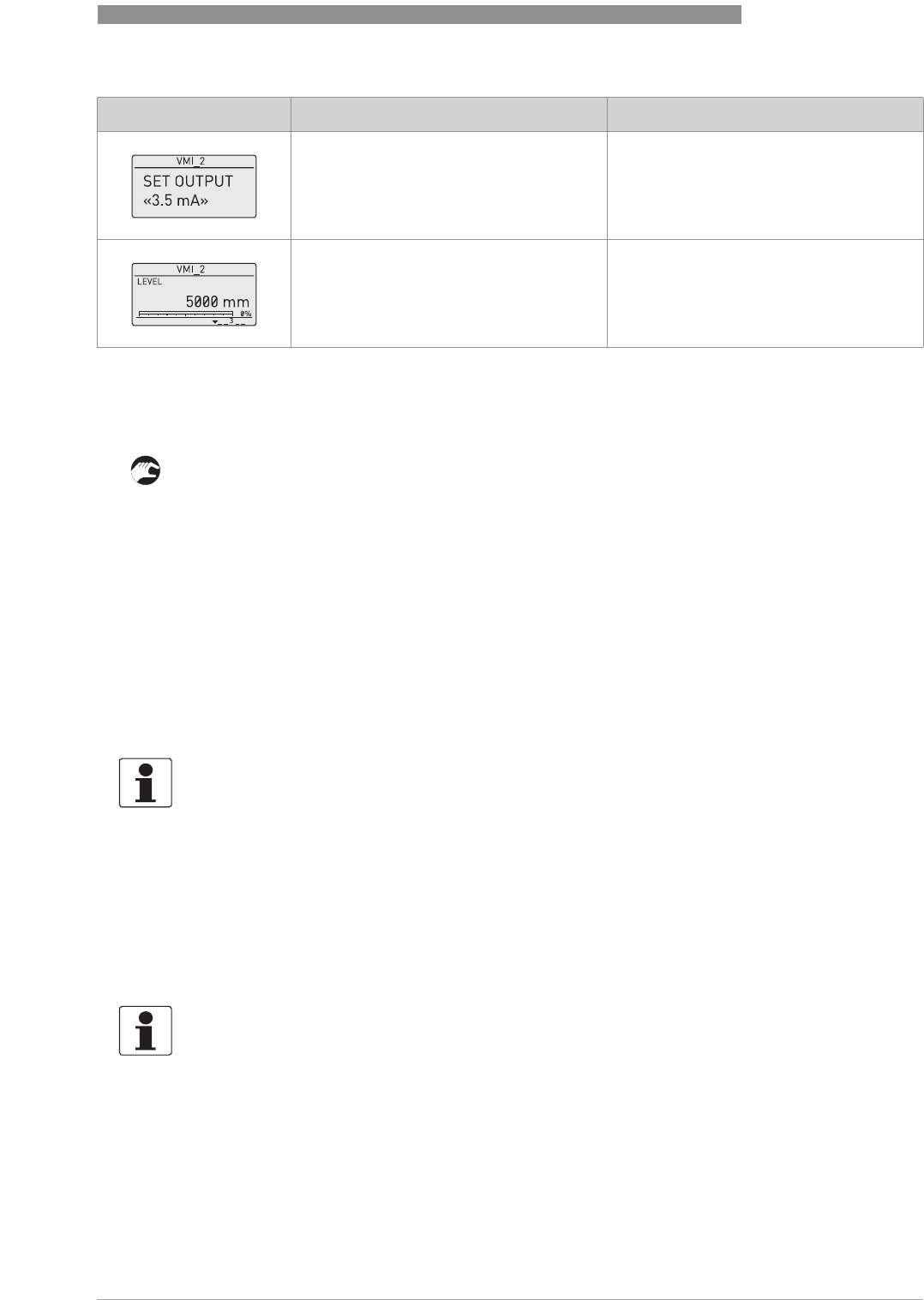
OPERATION
6
73
OPTIWAVE 7400-24 C
www.krohne.com12/2015 - 4003518001 - MA OPTIWAVE7400-24-R01-en
6.4.3 Protection of the device settings
The menu item PASSWORD (2.7.5) lets you change the supervisor menu password.
How to change the supervisor menu password
• After you enter the supervisor menu, push 6 × [
], [>
>>
>] and 4 × [
] to go to the menu item
PASSWORD (2.7.5).
• Enter the new 6-character password (push the 4 buttons in any sequence).
• Enter the new 6-character password again.
iIf the second entry is the same as the first, the device will go back to the sub-menu list
(2.7).If the second entry is not the same as the first, the device will not go back to the sub-
menu list. Push [^
^^
^] to start the password sequence again and enter the new 6-character
password 2 times.
• Push [^
^^
^] to go back to the "STORE" screen.
• Push [
] or [
] to set the screen to STORE YES
STORE YESSTORE YES
STORE YES and push [^
^^
^].
iThe device will save the new password and go back to normal mode.
How to set the supervisor password to "on" or "off"
The supervisor password is set to "on" by default. If it is necessary to set this function to "off"
refer to
Function description
on page 63, Table 2: Supervisor menu, menu item PSWD YES/NO
(2.7.4).
6.4.4 HART
®
network configuration
The device uses HART
®
communication to send information to HART
®
-compatible equipment. It
can operate in either point-to-point or multidrop mode. The device will communicate in
multidrop mode if you change the address.
•
[>
>>
>].
•
[
] to decrease the value or [
] to
increase the value.
•
[^
^^
^] to confirm.
This step sets the loop current value. Make
a selection from 3.5, 4, 6, 8, 10, 12, 14, 16,
18, 20 or 22 mA.
•
[^
^^
^] 3 times to go back to the default
screen.
The loop current goes back to initial value.
Default screen.
Screen Step Description
INFORMATION!
Make a note of the password and keep it in a safe place. If you lose the password, please speak
or write to your supplier.
INFORMATION!
For more data, refer to Networks on page 49
.
6
OPERATION
74
OPTIWAVE 7400-24 C
www.krohne.com 12/2015 - 4003518001 - MA OPTIWAVE7400-24-R01-en
How to change from point-to-point to multidrop mode
• Enter the supervisor menu.
• Push [>
>>
>], 5 × [
] and [>
>>
>] to go to menu item ADDRESS (2.6.1).
• Push [>
>>
>] to change the value. Enter a value between 1 and and push [^
^^
^] to confirm (refer to
the caution before this procedure).
• Push [^
^^
^] to go back to the "STORE" screen.
• Push [
] or [
] to set the screen to STORE YES
STORE YESSTORE YES
STORE YES and push [^
^^
^].
iThe output is set to multidrop mode. The current output is set to 4 mA. This value does not
change in multidrop mode.
How to change from multidrop to point-to-point mode
• Enter the supervisor menu.
• Push [>
>>
>], 5 × [
] and [>
>>
>] to go to menu item ADDRESS (2.6.1).
• Push [>
>>
>] to change the value. Enter the value 0 and push [^
^^
^] to confirm.
• Push [^
^^
^] to go back to the "STORE" screen.
• Push [
] or [
] to set the screen to STORE YES
STORE YESSTORE YES
STORE YES and push [^
^^
^].
iThe output is set to point-to-point mode. The current output changes to a range of 4...20 mA
or 3.8...20.5 mA (this range is set in menu item RANGE I (2.4.2)).
6.4.5 Distance measurement
The device displays distance measurements when the output function is set to "Distance".
Menu items related to distance measurement are:
•Output Function (2.4.1)
•Tank Height (2.3.1)
•Blocking Distance (2.3.2)
Use the flange facing as the reference point for the 4 and 20 mA current output settings. The 4
and 20 mA current output settings are the minimum and maximum points of the measurement
scale.
You can change the reference point from which distance is measured. Use this menu
item:
•Reference Offset (2.3.7)
CAUTION!
Make sure that the address for this device is different from others in the multidrop network.
INFORMATION!
If you move the reference point above the flange, add this value when you give a distance for the
4 and 20 mA current output settings. If you move the reference point below the flange, subtract
this value when you give a distance for the 4 and 20 mA current output settings.
CAUTION!
If the distance for 4 mA is set in the blocking distance, the device will not be able to use the full
current output range.

OPERATION
6
75
OPTIWAVE 7400-24 C
www.krohne.com12/2015 - 4003518001 - MA OPTIWAVE7400-24-R01-en
6.4.6 Level measurement
The device displays level measurements when the output function is set to "Level".
Menu items related to level measurement are:
•Output Function (2.4.1)
•Tank Height (2.3.1)
•Blocking Distance (2.3.2)
You can change the reference point from which level is measured. Use this menu item:
•Tank Bottom Offset (2.3.8)
Figure 6-4: Distance measurement
1 Tank Height (2.3.1)
2 Reference Offset (2.3.7)
3 Blocking Distance (2.3.2)
4 4mA Setting (2.4.3)
5 20 mA Setting (2.4.4)
6 Maximum effective measuring range
7 Non-measurement zone
CAUTION!
If the level for the 20 mA is set in the blocking distance, the device will not be able to use the full
current output range.
6
OPERATION
76
OPTIWAVE 7400-24 C
www.krohne.com 12/2015 - 4003518001 - MA OPTIWAVE7400-24-R01-en
6.4.7 How to configure the device to measure volume or mass
The device can be configured to measure volume or mass. You can set up a strapping table in the
conversion table (2.8.0 CONV. TAB) sub-menu. Each entry is a pair of data (level – volume, level –
mass or level – flow rate). The strapping table must have a minimum of 2 entries and a
maximum of 30. The reference point for the table is the bottom of the tank (as given in menu item
2.3.1 TANK HEIGHT).
How to prepare a strapping table (conversion table)
• Enter the supervisor menu.
• Push [>
>>
>], 6 × [
], [>
>>
>] and [
] to go to 2.7.2 LENGTH UNIT.
• Push [
] and [
] to find the length unit that you will use in the table.
• Push [^
^^
^] to go to the sub-menu level.
• Push [
] to go to 2.7.3 CONV UNIT (conversion unit)
• Push [
] and [
] to find the conversion unit that you will use in the table.
• Push [^
^^
^] to go to the sub-menu level and then [
] and [>
>>
>] to go to the menu item 2.8.1 INPUT
TAB
• Push [>
>>
>] to make the strapping table. Enter the table entry number (01).
• Enter the length value and push [^
^^
^].
• Enter the conversion value and push [^
^^
^].
• Push [>
>>
>] to enter the subsequent table entry number (02, 03, ..., 30).
• Repeat the last 3 steps to complete the table.
• Push [^
^^
^] to go back to the "STORE" screen.
• Push [
] or [
] to set the screen to STORE YES
STORE YESSTORE YES
STORE YES and push [^
^^
^].
Figure 6-5: Level measurement
1 Tank Bottom Offset (2.3.8)
2 Tank Height (2.3.1)
3 Blocking Distance (2.3.2)
4 Maximum effective measuring range
5 20 mA Setting (2.4.4)
6 4mA Setting (2.4.3)
7 Non-measurement zone
CAUTION!
Enter the data in numerical sequence (strapping table entry number 01, 02 etc.).
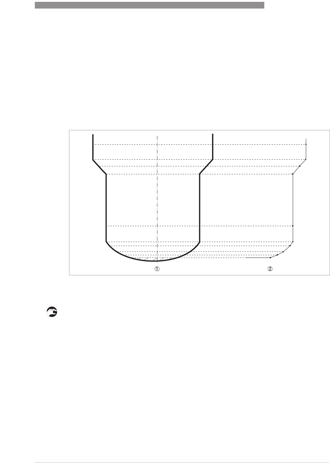
OPERATION
6
77
OPTIWAVE 7400-24 C
www.krohne.com12/2015 - 4003518001 - MA OPTIWAVE7400-24-R01-en
iThe device will store the data for the strapping table and go back to normal mode.
The device will give more accurate volume readings if you give more conversion data in these
areas:
•Surfaces with curves.
•Sudden changes in the cross section.
Refer also to the illustration that follows:
How to delete a volume or mass table
• Enter the supervisor menu.
• Push 7 × [
], [>
>>
>], and [
] to go to 2.8.2 DELETE TABLE.
• Push [>
>>
>] and [
] to set the parameter to YES
YESYES
YES.
• Push [^
^^
^] to go back to the "STORE" screen.
• Push [
] or [
] to set the screen to STORE YES
STORE YESSTORE YES
STORE YES and push [^
^^
^].
iThe device will delete the data for the strapping table and go back to normal mode. The
"CONVERSION" and "ULLAGE CONV." data are not available in normal mode.
6.4.8 How to make a filter to remove radar signal interference
If the device measures level in a tank that contains obstructions (agitator, supports, heating
pipes etc.), these objects can cause radar signal interference (parasitic signals). You can use the
empty spectrum function (menu item 2.1.2) in the Quick Setup menu to make a filter to remove
radar signal interference.
Figure 6-6: A plot of points for a volume or mass table
1
2
6
OPERATION
78
OPTIWAVE 7400-24 C
www.krohne.com 12/2015 - 4003518001 - MA OPTIWAVE7400-24-R01-en
6.4.9 How to measure correctly in tanks with curved or conical bottoms
You can offset the tank bottom reference point to find the delayed radar reflection. Obey the
instructions that follow:
•
• Increase the tank height in menu C.1.2.
• Go to the signal screen
signal screensignal screen
signal screen in operator mode.
iYou will see a graph of reflections.
• Push [>
>>
>] to move the cursor to the reflection with the largest amplitude (given in dB).
• Make a note of the distance of the reflection measured by the device.
iThe distance to the reflection will be the new tank height.
• Subtract the distance to the reflection from the true tank height.
• Go to Supervisor > Advanced Setup > Installation Setup > Tank Bottom Offset
Supervisor > Advanced Setup > Installation Setup > Tank Bottom OffsetSupervisor > Advanced Setup > Installation Setup > Tank Bottom Offset
Supervisor > Advanced Setup > Installation Setup > Tank Bottom Offset.
• Type in the difference you calculated as a negative value.
iA negative value will move the reference point above the tank bottom (as given in menu
item C.1.2 Tank height).
• Push [^
^^
^].
INFORMATION!
We recommend that you do an empty spectrum scan when the tank is empty and all the moving
parts (agitators etc.) are in operation..
Figure 6-7: How to make a filter to remove radar signal interference
1 Empty tank before the device uses the empty spectrum scan (with a graph of reflections shown)
2 Partially filled tank before the device uses the empty spectrum scan (with a graph of reflections shown)
3 Partially filled tank after the device uses the empty spectrum scan (with a graph of reflections shown)
4 Agitator blades location
5 Tank bottom signal
6 Agitator blades signals (interference signals) before the device does the empty spectrum scan
7 Bad quality (mixed) signals of the liquid and the agitator blades before the device does the empty spectrum scan
8 Reflected signal if the device uses the data from the empty spectrum scan. The device only uses the reflection on the
surface of the liquid to measure distance.
INFORMATION!
For more data on empty spectrum scans
–
table 2: Supervisor (menu item 2.1.2).
OPERATION
6
79
OPTIWAVE 7400-24 C
www.krohne.com12/2015 - 4003518001 - MA OPTIWAVE7400-24-R01-en
• Push [>
>>
>] and [
] (Esc) at the same time to exit to the "save settings" window.
• Select Save
SaveSave
Save and push [^
^^
^].
iThe device will go back to operator mode.
6.5 Status and error messages
6.5.1 Device status (markers)
If the device senses a change in device status, the display screen will show 1 or more status
markers at the bottom right side of the display screen. The display screen will also show a
symbol that agrees with NAMUR Recommendation NE 107 (Self-Monitoring and Diagnosis of
Field Devices) and VDI/VDE 2650. This is shown at the top left side of the display screen. More
data is given if you use PACTware™ software with the appropriate DTM on a PC. Error codes and
data are shown on the device display screen and in the DTM.
Menu item 2.2.2 DIAGNOSTIC (Configuration mode / Supervisor menu) supplies more data. This
includes internal voltages, the loop current and the reset counter (watchdog timer). You can see
this data on the device display screen and in the DTM.
Types of error message
INFORMATION!
For more data on menu items, refer to Function description on page 63
–
table 2: Supervisor.
Figure 6-8: Status markers
1 Device status (NAMUR NE 107 symbols)
2 Symbol: Failure
3 Symbol: Function check
4 Symbol: Out of specification
5 Symbol: Maintenance
6 Status marker line (marker 3 is shown)
7 When the status marker is on, a number is shown
NE 107 status Type of
error
Description
Failure Error If an error message is shown in ERROR RECORD (menu item 1.3.1), the current
output goes to the error signal value set in menu item RANGE I (menu item 2.4.2)
after the time set in ERROR DELAY (menu item 2.4.5). For more data about menu
items.
Out of specification Warning If a warning message is shown, there is no effect on the current output value.
Maintenance
6
OPERATION
80
OPTIWAVE 7400-24 C
www.krohne.com 12/2015 - 4003518001 - MA OPTIWAVE7400-24-R01-en
If an "Out of specification" or a "Maintenance" status symbol is shown, refer to menu item 2.2.2
DIAGNOSTIC (Configuration mode / Supervisor menu) for more data.
For data on errors, error records and error codes, refer to
Error handling
on page 80.
6.5.2 Error handling
How to find an error record
• Push [>
>>
>] to enter configuration mode from normal mode.
• Push [>
>>
>], 2 × [
] and [>
>>
>] to go to menu item 1.3.1 ERROR RECORD.
• Push 2 × [>
>>
>] to look at the error list. Push [
] or [
] for the selection of an error.
iThe error record gives the number of times the error occurred and the time since the last
error message.
Description of errors and corrective actions
Figure 6-9: Error record data
1 Error code for the error
2 Number of times the error occurred
3 Time since the last error record (2 days, 18 hours, 16 minutes and 43 seconds shown in this example)
INFORMATION!
The time since the error occurred is measured in Days (D), Hours (H), Minutes(') and Seconds (").
It only includes the time when the device is energized. The error is saved in the memory of the
device when it is de-energized. The counter continues when the device is energized again.
Error
code
Error Message Status marker
shown
Cause Corrective action
Failure (NE 107 status signal)
ERR 100 Device reset 1The device detected an internal
error (watchdog timer issue). Record the data that is in menu
item 2.2.2 DIAGNOSTIC
(Configuration mode /
Supervisor menu). Speak to the
supplier.

OPERATION
6
81
OPTIWAVE 7400-24 C
www.krohne.com12/2015 - 4003518001 - MA OPTIWAVE7400-24-R01-en
ERR 101 Current Output Drift 1The current output is not
calibrated. Speak to the supplier to get the
calibration procedure.
1Hardware error. Replace the device.
ERR 102 Temperature out of
range 1The ambient temperature is
outside the given range. This
can cause loss or corruption of
data.
Measure the ambient
temperature. De-energize the
device until the ambient
temperature is back in the given
range. If the temperature does
not stay in the correct range,
make sure that there is
insulation around the signal
converter. If this error occurs 2
times, replace the device.
ERR 103 Converter memory
failure 1The device's hardware is
defective. Replace the signal converter.
For more data, refer to
How to
turn or remove the signal
converter
on page 36.
ERR 104 Converter Voltage
failure 1The device's hardware is
defective. Replace the signal converter.
For more data, refer to
How to
turn or remove the signal
converter
on page 36.
ERR 200 Internal
Communication 1The device's hardware or
software is defective. The
converter cannot transmit
signals to or receive signals
from the antenna electronics.
De-energize the device. Make
sure that the signal cable
engages in the terminal and the
screw connection is tight.
Energize the device. If the
problem continues, replace the
signal converter. For more data,
refer to
How to turn or remove
the signal converter
on page 36.
ERR 201 Overfill 2The level is in the blocking
distance. There is a risk that the
product will overflow and/or
cover the antenna.
Use a different procedure to
measure the level in the tank.
Remove some of the product
until the level is below the
blocking distance.
If a viscous product touched the
antenna:
•
remove the device and clean
the antenna, or
•
If the device has a purging
option, use the purging system
to clean the antenna.
ERR 203 Peak Lost (Level
Lost) 2The signal peak is not found
within the measuring window
that filters the signals received
by the antenna. The
measurement is not correct.
The device will automatically
increase this window to find the
correct signal.
Do a check of the device, tank
and the process. Reconfigure
the device and record a new
empty spectrum. Follow the
instructions on page 77. If
necessary, speak to the
supplier.
ERR 204 Sensor no Signal 3The device's hardware is
defective. Replace the signal converter.
For more data, refer to
How to
turn or remove the signal
converter
on page 36.
ERR 206 Sensor Microwave
failure 1The device's hardware is
defective. Replace the signal converter.
For more data, refer to
How to
turn or remove the signal
converter
on page 36.
Error
code
Error Message Status marker
shown
Cause Corrective action

6
OPERATION
82
OPTIWAVE 7400-24 C
www.krohne.com 12/2015 - 4003518001 - MA OPTIWAVE7400-24-R01-en
ERR 207 Sensor Memory
failure 1The device's hardware is
defective. Replace the signal converter.
For more data, refer to
How to
turn or remove the signal
converter
on page 36.
ERR 208 Sensor Voltage
failure 3The device's hardware is
defective. Do a check of the power supply
at the device terminals. Make
sure that voltage values are in
the specified limits in menu
item 2.2.2 DIAGNOSTIC
(Configuration mode /
Supervisor menu). If the voltage
is correct, replace the signal
converter. For more data on
how to replace the signal
converter, refer to
How to turn
or remove the signal converter
on page 36.
ERR 210 Sensor Not
compatible 1The software version of the
sensor is not compatible with
the software version of the
signal converter.
Go to menu 1.1.0 IDENT. in
Configuration mode. Record the
version numbers of the device
software given in menu items
1.1.2, 1.1.3 and 1.1.4. Give this
data to the supplier.
1Defective wiring.
Out of specification (NE 107 status signal)
ERR 102 Temperature Out of
Range 1The ambient temperature is
outside the given range. This
can cause loss or corruption of
data.
Measure the ambient
temperature. De-energize the
device until the ambient
temperature is back in the given
range. If the temperature does
not stay in the correct range,
make sure that there is
insulation around the signal
converter. If this error occurs 2
times, replace the device.
ERR 201 Overfill 2The level is in the blocking
distance. There is a risk that the
product will overflow and/or
cover the device.
Remove some of the product
until the level is below the
blocking distance.
ERR 203 Peak Lost 2The signal peak is not found
within the measuring window
that filters the signals received
by the antenna. The
measurement is not correct.
The device will automatically
increase this window to find the
correct signal.
Do a check of the device, tank
and the process and make sure
that the data agrees with the
device configuration. If
necessary, record a new empty
spectrum. Follow the
instructions on page 77. If
necessary, speak to the
supplier.
Maintenance (NE 107 status signal)
—Empty Spectrum
Invalid 5The empty spectrum stored in
the device does not agree with
the installation. If you change
the device configuration (tank
height etc.), this message will
be shown. The recorded empty
spectrum will not be used by
the device while this error
message is shown. 1
Record a new empty spectrum.
Follow the instructions on page
77.
Error
code
Error Message Status marker
shown
Cause Corrective action

OPERATION
6
83
OPTIWAVE 7400-24 C
www.krohne.com12/2015 - 4003518001 - MA OPTIWAVE7400-24-R01-en
—Signal Weak 4The signal amplitude is less
than the average value. This can
occur if the liquid is agitated or
if there is foam in the tank. If
this error occurs frequently, the
device will possibly show the
"Peak Lost (Level Lost)" error
message. 1
If this error occurs frequently, it
is possible that you must install
the device in a stilling well or
use a different antenna type.
—Signal Strong 4This error can occur if there is a
large change in signal
amplitude. 1
No corrective action is
necessary.
—Bad Measurement
Quality 4The measurement is incorrect
and continues to be incorrect
after more than 10 s. This error
can occur if the tank contents
are immediately below the
antenna. 1
Record the process with the
PACTware™ software tool to
find the cause of the problem. If
necessary, speak to the
supplier.
—Temperature <-
35°C/ -31°F3The process connection or the
ambient temperature is less
than -35°C/ -31°F. This
temperature is near to the
minimum limit for device
operation. 1
Measure the ambient
temperature. De-energize the
device until the ambient
temperature is back in the given
range. If the temperature does
not stay in the correct range,
make sure that there is
insulation around the signal
converter.
—Temperature
>+75°C / +167°F3The ambient temperature is
more than +75°C / +167°F. This
temperature is near to the
maximum limit for device
operation. 1
Measure the ambient
temperature. De-energize the
device until the ambient
temperature is back in the given
range. If the temperature does
not stay in the correct range,
make sure that there is
insulation around the signal
converter.
1This error message does not have an effect on the current output signal
Error
code
Error Message Status marker
shown
Cause Corrective action
7
SERVICE
84
OPTIWAVE 7400-24 C
www.krohne.com 12/2015 - 4003518001 - MA OPTIWAVE7400-24-R01-en
7.1 Periodic maintenance
7.2 How to clean the top surface of the device
Obey these instructions:
• Keep the thread of the terminal compartment cover clean.
• If dirt collects on the device, clean it.
7.3 How to clean horn antennas under process conditions
If it is possible that there will be build-up, a purging option is available for horn antennas.
For more data, refer to the table that follows:
7.4 How to replace device components
7.4.1 Service warranty
Servicing by the customer is limited by warranty to:
•The removal and installation of the device.
•Compact version:
Compact version:Compact version:
Compact version: The removal and installation of the signal converter (with the weather
protection, if this option is attached). For more data, refer to
How to turn or remove the signal
converter
on page 36.
•Remote (field) version:
Remote (field) version:Remote (field) version:
Remote (field) version: The removal and installation of the remote converter and/or the
antenna housing. For more data, refer to
How to turn or remove the signal converter
on page
36.
For more data on how to prepare the device before you send it back, refer to
Returning the
device to the manufacturer
on page 88.
INFORMATION!
For more data about regular inspections and maintenance procedures for devices with Ex and
other approvals, refer to the related supplementary instructions.
WARNING!
Do not let more than 5 mm / 0.2
¨
of dust collect on the top surface of the device. This is a
possible source of ignition in a potentially explosive atmosphere.
CAUTION!
Purge the antenna at intervals to make sure that the inner surface of the antenna stays clean
and the device measures accurately.
WARNING!
Only approved personnel can do an inspection of the device and repairs. If you find a problem,
send the device back to the supplier for inspection and/or repairs.
INFORMATION!
The converter housing (compact or remote version) can be detached from the process
connection assembly under process conditions. For more data, refer to How to turn or remove
the signal converter on page 36
.
SERVICE
7
85
OPTIWAVE 7400-24 C
www.krohne.com12/2015 - 4003518001 - MA OPTIWAVE7400-24-R01-en
7.4.2 Replacement of the OPTIWAVE 7300 signal converter with the OPTIWAVE 7400
signal converter
Equipment needed:
•5 mm Allen wrench (not supplied)
•Slotted-tip screwdriver (not supplied)
•Wrench for housing cover
•Yellow / blue magnet
•OPTIWAVE 7300 C radar level meter
•OPTIWAVE 7400 signal converter (without process connection and antenna)
•Handbooks for all devices
Procedure 1: Record the offset value (OPTIWAVE7300 radar level meter)
1 Energize the device.
iThe device is in operation and in normal mode.
2 Push [^
^^
^] to go to the SERVICE menu.
iThe display screen shows the text "Code 2".
3 Give the password for the SERVICE menu. If you do not have the password, speak to the sup-
plier.
4 Push [>
>>
>], [
] and [>
>>
>] to go to menu item 4.2.1 Offset. Record the offset value.
5 Push 4 × [^
^^
^]. Push [
] or [
] for the selection of the save option (Store No, Store Yes or Re-
turn). Set to "Store No" to cancel the changes to the device settings.
6 Push [^
^^
^] to confirm.
iThe device is in normal mode.
7 De-energize the device.
8 Remove the electrical cables.
9 Attach the signal converter cover.
INFORMATION!
Complete the 5 procedures that follow in numerical sequence.
To get the passwords for the OPTIWAVE 7300 and OPTIWAVE 7400 Service menus, speak to the
supplier.
CAUTION!
Make sure that you also record device configuration data. This data includes basic configuration
(tank height, blocking distance etc.), output, application, display and strapping table data. You
can find this data in the Supervisor menu.
INFORMATION!
If you cannot start the device, record the serial number on the device nameplate and contact the
supplier. The supplier will give you the offset value.
7
SERVICE
86
OPTIWAVE 7400-24 C
www.krohne.com 12/2015 - 4003518001 - MA OPTIWAVE7400-24-R01-en
1 Remove the 4 socket head screws at the bottom of the signal converter with a 5 mm Allen
wrench. Keep the screws for the subsequent procedure.
2 Remove the signal converter from the process connection. Make sure that the gasket stays on
the flange connection.
1 Put the OPTIWAVE 7400 signal converter on the flange connection. Make sure that the signal
converter fully engages in the mating part.
2 Tighten the socket set screw at the bottom of the signal converter with a 5 mm Allen wrench.
Procedure 4: How to set the correct offset value (OPTIWAVE 7400)
1 Energize the device.
iThe device is in operation and in normal mode. It will not measure correctly until the new
correction offset value is set in menu item 3.1.4 CORR.OFFSET.
2 Push [>
>>
>], 2 × [
] and [>
>>
>] to go to the SERVICE menu (3.0.0).
3 Give the password for the SERVICE menu. If you do not have the password, speak to the sup-
Procedure 2: How to remove the signal converter (OPTIWAVE 7300 C radar level
meters)
Figure 7-1: Procedure 2: How to remove the signal converter (OPTIWAVE 7300 C radar level meters)
Procedure 3: How to attach the OPTIWAVE 7400 signal converter
Figure 7-2: Procedure 3: How to attach the OPTIWAVE 7400 signal converter
SERVICE
7
87
OPTIWAVE 7400-24 C
www.krohne.com12/2015 - 4003518001 - MA OPTIWAVE7400-24-R01-en
plier.
4 Push [>
>>
>] and 3 × [
] to go to menu item 3.1.4 CORR.OFFSET (correction offset).
5 Push [>
>>
>] to change the value. Enter the new correction offset value. For the applicable correc-
tion offset value, refer to the table that follows.
6 Push 4 × [>
>>
>]. Push [
] or [
] for the selection of the save option (STORE NO or STORE YES).
Set to "STORE YES" to save and use the data.
7 Push [^
^^
^] to confirm.
iThe device is in normal mode. The device uses the new correction offset value.
Procedure 5: Device configuration (OPTIWAVE 7400)
1 For the Quick Setup procedure, refer to
Quick Setup (Commissioning)
on page 70. For more
data about device configuration, refer to
Operation
on page 56.
7.5 Spare parts availability
The manufacturer adheres to the basic principle that functionally adequate spare parts for each
device or each important accessory part will be kept available for a period of 3 years after
delivery of the last production run for the device.
This regulation only applies to spare parts which are subject to wear and tear under normal
operating conditions.
7.6 Availability of services
The manufacturer offers a range of services to support the customer after expiration of the
warranty. These include repair, maintenance, technical support and training.
CAUTION!
You recorded device configuration data of the OPTIWAVE 7300 level meter before you attached
the new signal converter. Make sure that you enter this data in the supervisor menu of the
OPTIWAVE 7400.
INFORMATION!
For more precise information, please contact your local sales office.

7
SERVICE
88
OPTIWAVE 7400-24 C
www.krohne.com 12/2015 - 4003518001 - MA OPTIWAVE7400-24-R01-en
7.7 Returning the device to the manufacturer
7.7.1 General information
This device has been carefully manufactured and tested. If installed and operated in accordance
with these operating instructions, it will rarely present any problems.
CAUTION!
Should you nevertheless need to return a device for inspection or repair, please pay strict
attention to the following points:
•
Due to statutory regulations on environmental protection and safeguarding the health and
safety of the personnel, the manufacturer may only handle, test and repair returned devices
that have been in contact with products without risk to personnel and environment.
•
This means that the manufacturer can only service this device if it is accompanied by the
following certificate (see next section) confirming that the device is safe to handle.
CAUTION!
If the device has been operated with toxic, caustic, flammable or water-endangering products,
you are kindly requested:
•
to check and ensure, if necessary by rinsing or neutralising, that all cavities are free from
such dangerous substances,
•
to enclose a certificate with the device confirming that is safe to handle and stating the
product used.
SERVICE
7
89
OPTIWAVE 7400-24 C
www.krohne.com12/2015 - 4003518001 - MA OPTIWAVE7400-24-R01-en
7.7.2 Form (for copying) to accompany a returned device
7.8 Disposal
CAUTION!
To avoid any risk for our service personel, this form has to be accessible from outside of the
packaging with the returned device.
Company: Address:
Department: Name:
Tel. no.: Fax no. and/or Email address:
Manufacturer's order no. or serial no.:
The device has been operated with the following medium:
This medium is: radioactive
water-hazardous
toxic
caustic
flammable
We checked that all cavities in the device are free from such substances.
We have flushed out and neutralized all cavities in the device.
We hereby confirm that there is no risk to persons or the environment through any residual media contained in the
device when it is returned.
Date: Signature:
Stamp:
CAUTION!
Disposal must be carried out in accordance with legislation applicable in your country.
Separate collection of WEEE (Waste Electrical and Electronic Equipment) in the European Union:
Separate collection of WEEE (Waste Electrical and Electronic Equipment) in the European Union:Separate collection of WEEE (Waste Electrical and Electronic Equipment) in the European Union:
Separate collection of WEEE (Waste Electrical and Electronic Equipment) in the European Union:
According to the directive 2012/19/EU, the monitoring and control instruments marked with the
WEEE symbol and reaching their end-of-life must not be disposed of with other waste
must not be disposed of with other wastemust not be disposed of with other waste
must not be disposed of with other waste.
The user must dispose of the WEEE to a designated collection point for the recycling of WEEE or
send them back to our local organisation or authorised representative.
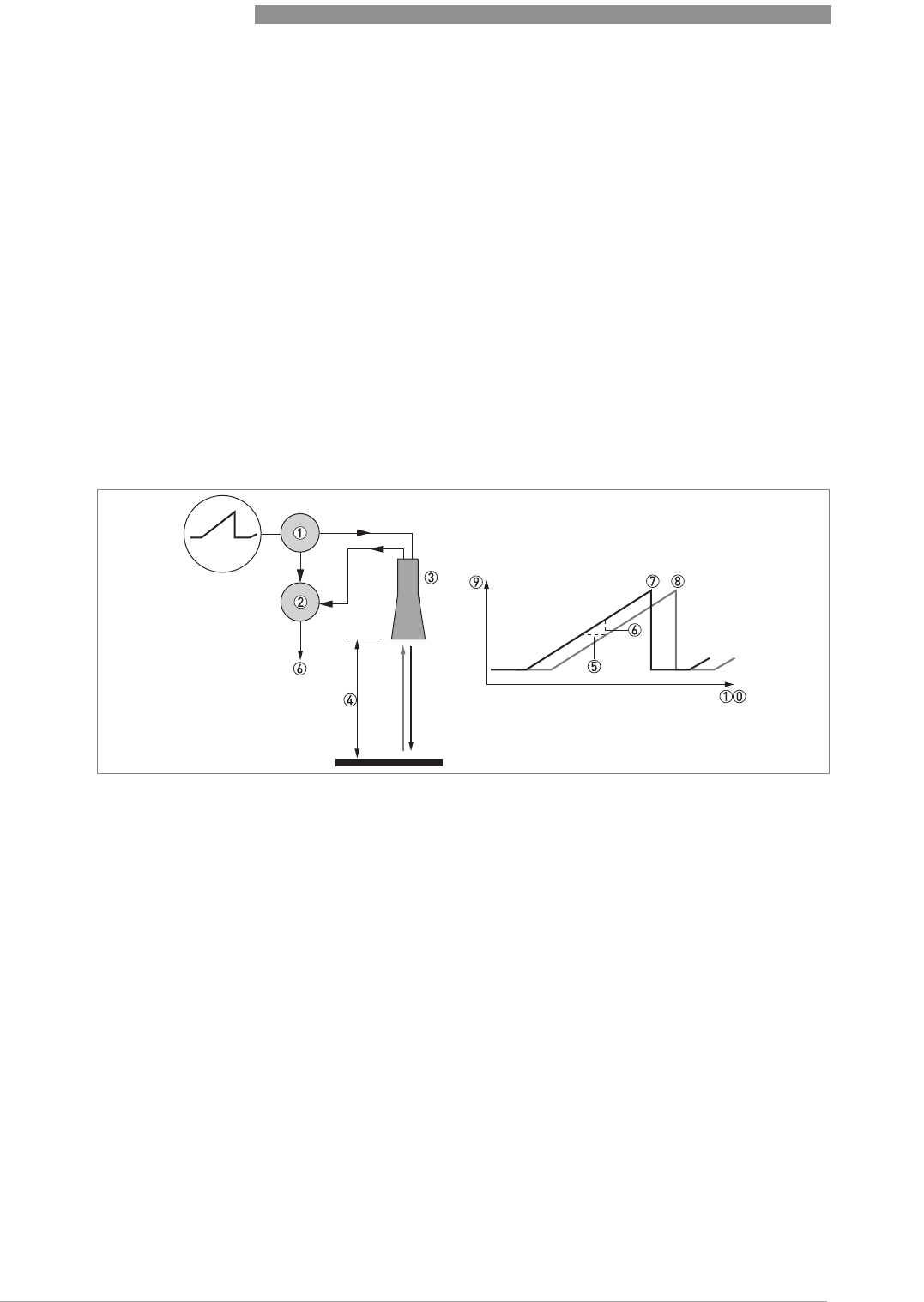
8
TECHNICAL DATA
90
OPTIWAVE 7400-24 C
www.krohne.com 12/2015 - 4003518001 - MA OPTIWAVE7400-24-R01-en
8.1 Measuring principle
A radar signal is emitted via an antenna, reflected from the product surface and received after a
time t. The radar principle used is FMCW (Frequency Modulated Continuous Wave).
The FMCW-radar transmits a high frequency signal whose frequency increases linearly during
the measurement phase (called the frequency sweep). The signal is emitted, reflected on the
measuring surface and received with a time delay, t. Delay time, t=2d/c, where d is the distance
to the product surface and c is the speed of light in the gas above the product.
For further signal processing the difference Δf is calculated from the actual transmitted
frequency and the received frequency. The difference is directly proportional to the distance. A
large frequency difference corresponds to a large distance and vice versa. The frequency
difference Δf is transformed via a Fourier transformation (FFT) into a frequency spectrum and
then the distance is calculated from the spectrum. The level results from the difference between
the tank height and the measured distance.
Figure 8-1: Measuring principle of FMCW radar
1 Transmitter
2 Mixer
3 Antenna
4 Distance to product surface, where change in frequency is proportional to distance
5 Differential time delay, Δt
6 Differential frequency, Δf
7 Frequency transmitted
8 Frequency received
9 Frequency
10 Time

TECHNICAL DATA
8
91
OPTIWAVE 7400-24 C
www.krohne.com12/2015 - 4003518001 - MA OPTIWAVE7400-24-R01-en
8.2 Technical data
INFORMATION!
•
The following data is provided for general applications. If you require data that is more
relevant to your specific application, please contact us or your local sales office.
•
Additional information (certificates, special tools, software,...) and complete product
documentation can be downloaded free of charge from the website (Downloadcenter).
Measuring system
Measuring principle 2-wire loop-powered level transmitter; K-band (24...26 GHz) FMCW radar
Application range Level measurement of liquids, pastes and slurries
Primary measured value Distance and reflection
Secondary measured value Level, volume, mass and flow rate
Design
Construction The measurement system consists of a measuring sensor (antenna) and a signal
converter
Options Integrated LCD display (-20..+60°C/ -4…+140°F); if the ambient temperature is not
in these limits, the display switches off automatically
Straight antenna extensions (length 105 mm / 4.1¨)
Max. extension length, Drop antenna: 525 mm / 20.7¨;
Not available for the Hygienic antenna
Antenna purging system (supplied with a ¼NPTF connection)
PTFE/PP flange plate protection (for Drop antennas without antenna extensions
only)
Distance piece (for process temperature: +150...+200°C / +302...+392°F) 1
Signal cable for remote housing version (refer to cable properties in "Electrical
connection: Remote device version")
Weather protection
Max. measuring range 80 m / 260 ft
Also depends on the dielectric constant of the product and the installation type.
Refer also to "Antenna selection".
Min. tank height 0.2 m / 8¨ (1 m / 40¨ for hygienic antenna)
Top dead zone Antenna extension length + antenna length + 0.1 m / 4¨ (500 mm / 20¨ for hygienic
antenna)
Beam angle Metallic Horn (machined) DN 40 (1.5¨): 20°
Metallic Horn (machined) DN 50 (2¨): 15°
Metallic Horn (sheet metal) DN 65 (2.5¨): not appicable. This antenna option is for
the BM 26 W.
Metallic Horn (sheet metal) DN 80 (3¨): 10°
Metallic Horn (sheet metal) DN 100 (4¨): 8°
Metallic Horn DN150 / 6¨: 6°
Metallic Horn DN200 / 8¨: 4°
Drop DN80 / 3¨: 8°
Drop DN150 / 6¨: 4°
Hygienic DN50 / 2¨: 15°

8
TECHNICAL DATA
92
OPTIWAVE 7400-24 C
www.krohne.com 12/2015 - 4003518001 - MA OPTIWAVE7400-24-R01-en
Display and user interface
Display and user interfaceDisplay and user interface
Display and user interface
Display LCD display
128 × 64 pixels in 8-step greyscale with 4-button keypad
Interface languages 4 language pack options (the language is given in the customer order):
1 English, French German and Italian
2 English, French,Spanish and Portuguese
3 English, Chinese (simplified), Japanese and Russian
4 English, Czech, Polish and Turkish
Measuring accuracy
Resolution 1mm/ 0.04¨
Repeatability ±1mm/ ±0.04¨
Accuracy Standard: ±2mm/ ±0.8¨, when distance <10m/ 33ft;
±0.2% of measured distance, when distance > 10 m / 33 ft
Reference conditions acc. to EN 61298-1
Reference conditions acc. to EN 61298-1Reference conditions acc. to EN 61298-1
Reference conditions acc. to EN 61298-1
Temperature +15...+25°C / +59...+77°F
Pressure 1013 mbara ±50 mbar / 14.69 psia ±0.73 psi
Relative air humidity 60% ±15%
Target Metal plate in an anechoic chamber
Operating conditions
Temperature
TemperatureTemperature
Temperature
Ambient temperature -40…+80°C/ -40…+176°F
Ex: see supplementary operating instructions or approval certificates
Storage temperature -50…+85°C/ -58…+185°F
Process connection temperature
(higher temperature on request) Metallic Horn (machined) / Metallic Horn (sheet metal) antenna:
Metallic Horn (machined) / Metallic Horn (sheet metal) antenna:Metallic Horn (machined) / Metallic Horn (sheet metal) antenna:
Metallic Horn (machined) / Metallic Horn (sheet metal) antenna:
Standard: -50…+150°C/ -58…+302°F
Option: -50…+200°C/ -58…+392°F
(the process connection temperature must agree with the temperature limits of the
gasket material. Refer to "Materials" in this table.)
Ex: see supplementary operating instructions or approval certificates
Drop antenna (PTFE):
Drop antenna (PTFE):Drop antenna (PTFE):
Drop antenna (PTFE):
-50…+150°C/ -58…+302°F (the process connection temperature must agree with
the temperature limits of the gasket material. Refer to "Materials" in this table.)
Ex: see supplementary operating instructions or approval certificates
Drop antenna (PP):
Drop antenna (PP):Drop antenna (PP):
Drop antenna (PP):
-40…+100°C/ -40…+212°F (the process connection temperature must agree with
the temperature limits of the gasket material. Refer to "Materials" in this table.)
Ex: see supplementary operating instructions or approval certificates
Drop antenna (PEEK):
Drop antenna (PEEK):Drop antenna (PEEK):
Drop antenna (PEEK):
-20…+200°C/ -4…+392°F (the process connection temperature must agree with
the temperature limits of the gasket material. Refer to "Materials" in this table.)
Ex: see supplementary operating instructions or approval certificates
Hygienic antenna (PEEK):
Hygienic antenna (PEEK):Hygienic antenna (PEEK):
Hygienic antenna (PEEK):
-20…+150°C/ -4…+302°F (the process connection temperature must agree with
the temperature limits of the gasket material. Refer to "Materials" in this table.)
Ex: see supplementary operating instructions or approval certificates

TECHNICAL DATA
8
93
OPTIWAVE 7400-24 C
www.krohne.com12/2015 - 4003518001 - MA OPTIWAVE7400-24-R01-en
Pressure
PressurePressure
Pressure
Process pressure Drop antenna (PP):
Drop antenna (PP):Drop antenna (PP):
Drop antenna (PP):
-1…16 barg / -14.5…232 psig;
subject to the process connection used and the flange temperature. For more data,
refer to
Guidelines for maximum operating pressure
on page 101.
Drop antenna (PTFE):
Drop antenna (PTFE):Drop antenna (PTFE):
Drop antenna (PTFE):
-1…40 barg / -14.5…580 psig;
subject to the process connection used and the flange temperature. For more data,
refer to
Guidelines for maximum operating pressure
on page 101.
Drop antenna (PEEK):
Drop antenna (PEEK):Drop antenna (PEEK):
Drop antenna (PEEK):
-1...40 barg / -14.5…580 psig;
subject to the process connection used and the flange temperature
Hygienic antenna (PEEK):
Hygienic antenna (PEEK):Hygienic antenna (PEEK):
Hygienic antenna (PEEK):
-1…10 barg / -14.5…145 psig;
subject to the process connection used and the flange temperature
Metallic Horn (machined) / Metallic Horn (sheet metal) antenna:
Metallic Horn (machined) / Metallic Horn (sheet metal) antenna:Metallic Horn (machined) / Metallic Horn (sheet metal) antenna:
Metallic Horn (machined) / Metallic Horn (sheet metal) antenna:
Standard: -1…40 barg / -14.5…580 psig;
Option: -1…100 barg / -14.5…1450 psig;
subject to process connection used and flange temperature
Other conditions
Other conditionsOther conditions
Other conditions
Dielectric constant (ε
r
)Direct mode: ≥1.8
TBF mode: ≥1.1
Refer also to "Technical data: Antenna selection".
Ingress protection IEC 60529: IP 66/67
NEMA 250: NEMA type 4X (housing) and type 6P (antenna)
Maximum rate of change 10 m/min / 32.8 ft/min
Installation conditions
Process connection size The nominal diameter (DN) should be equal to or larger than the antenna diameter.
If the nominal diameter (DN) is smaller than the antenna, either:
– provide the means to adapt the device to a larger process connection on the tank
(for example, a plate with a slot), or
– use the same process connection, but remove the antenna from the device before
installation and fit it from inside the tank.
Process connection position Make sure that there are not any obstructions directly below the process
connection for the device. For more data, refer to
Installation
on page 23.
Dimensions and weights For dimensions and weights data, refer to
Dimensions and weights
on page 103.
Materials
Housing Standard: Polyester-coated aluminium
Option: Stainless steel (1.4404 / 316L)
Wetted parts, including antenna Standard (Metallic Horn antenna): Stainless steel (1.4404 / 316L)
Option for MetallicHorn antenna: HASTELLOY® C-22® (2.4602) 2
Standard for Drop antenna: PTFE; PP; PEEK
Option for Drop antenna: PP, PTFE or PEEK flange plate protection
Hygienic antenna: PEEK – this material agrees with FDA regulations
Process connection Standard for Metallic Horn and Drop antennas:
Stainless steel (1.4404 / 316L) – a PP, PTFE or PEEK flange plate protection option
is also available for the Drop antenna
Standard for Hygienic antenna: PEEK
Option: HASTELLOY® C-22® (2.4602) – for Horn antennas only

8
TECHNICAL DATA
94
OPTIWAVE 7400-24 C
www.krohne.com 12/2015 - 4003518001 - MA OPTIWAVE7400-24-R01-en
Gaskets (and o-rings for the
sealed antenna extension option) Hygienic antenna:
Hygienic antenna:Hygienic antenna:
Hygienic antenna:
BioControl®: FKM/FPM (-20…+150°C/ -4…+302°F);
EPDM (-20°C…+150°C/ -4…+302°F)
SMS, Tri-Clamp®, VARIVENT®, DIN 11851: without 3
PTFE Drop antenna:
PTFE Drop antenna:PTFE Drop antenna:
PTFE Drop antenna:
FKM/FPM (-40…+150°C/ -40…+302°F); Kalrez® 6375 (-20…+150°C/ -4…+302°F);
EPDM (-50°C…+150°C/ -58…+302°F) 4
PP Drop antenna:
PP Drop antenna:PP Drop antenna:
PP Drop antenna:
FKM/FPM (-40…+100°C/ -40…+212°F); Kalrez® 6375 (-20…+100°C/ -4…+212°F);
EPDM (-40°C…+100°C/ -40…+212°F) 4
PEEK Drop antenna:
PEEK Drop antenna:PEEK Drop antenna:
PEEK Drop antenna:
FKM/FPM (-40…+200°C/ -40…+392°F); Kalrez® 6375 (-20…+200°C/ -4…+392°F);
EPDM (-40°C…+150°C/ -40…+203°F) 4
Metallic Horn antenna:
Metallic Horn antenna:Metallic Horn antenna:
Metallic Horn antenna:
FKM/FPM (-40…+200°C/ -40…+390°F); Kalrez® 6375 (-20…+200°C/ -4…+390°F);
EPDM (-50°C…+150°C/ -58…+300°F)
Feedthrough Standard: PEI (-50...+200°C / -58...+392°F – max. range. The feedthrough
temperature limits must agree with the temperature limits of the gasket material
and antenna type. If the distance piece option is not attached, the maximum
temperature is 150°C/ 300°F.)
Option: Metaglas® (-30...+200°C / -22...+392°F – max. range. The feedthrough
temperature limits must agree with the temperature limits of the gasket material
and antenna type. If the distance piece option is not attached, the maximum
temperature is 150°C/ 300°F.)
Cable gland Standard: none
Options: Plastic (Non-Ex: black, Ex i-approved: blue); nickel-plated brass; stainless
steel
Weather protection (Option) Stainless steel (1.4404 / 316L)
Process connections
Thread G1½ (ISO 228); 1½NPT (ASME B1.20.1)
Flange version
Flange versionFlange version
Flange version
EN 1092-1 DN40…200 in PN16 or PN40 (Type B1), DN40…150 in PN63 or PN100 (Type B1);
others on request
Optional flange facing: Types C, D, E and F
ASME B16.5 1½¨…8¨ in 150 lb RF, 1½¨...6¨ in 300 lb RF, 1½¨...4¨ in 600 lb or 900 lb RF; 1½¨...2¨ in
1500 lb RJ; others on request
Optional flange facing: RJ (Ring Joint)
JIS B2220 40…100A in 10K; others on request
Hygienic BioControl® DN50; Tri-Clamp® 2¨; DIN 11851 DN50; SMS 51; VARIVENT® DN50;
others on request
Other Others on request
Electrical connections
Power supply Terminals output
Terminals output Terminals output
Terminals output – Non-Ex / Ex i:
Non-Ex / Ex i: Non-Ex / Ex i:
Non-Ex / Ex i:
14…30 VDC; min./max. value for an output of 22 mA at the terminals
Terminals output
Terminals output Terminals output
Terminals output – Ex d:
Ex d: Ex d:
Ex d:
20…36 VDC; min./max. value for an output of 22 mA at the terminals
Maximum current 22 mA
Current output load Non-Ex / Ex i:
Non-Ex / Ex i:Non-Ex / Ex i:
Non-Ex / Ex i: R
L
[Ω] ≤ ((U
ext
-12 V)/22 mA). For more data, refer to
Minimum power
supply voltage
on page 99.
Ex d:
Ex d:Ex d:
Ex d: R
L
[Ω] ≤ ((U
ext
-16 V)/22 mA). For more data, refer to
Minimum power supply
voltage
on page 99.
Cable entry Standard: M20×1.5; Option: ½NPT

TECHNICAL DATA
8
95
OPTIWAVE 7400-24 C
www.krohne.com12/2015 - 4003518001 - MA OPTIWAVE7400-24-R01-en
Cable gland Standard: none
Options: M20×1.5 (cable diameter: 7…12 mm / 0.28…0.47¨); others are available on
request
Cable entry capacity (terminal) 0.5…2.5 mm²
Input and output
Current output / HART
Current output / HARTCurrent output / HART
Current output / HART®
Output signal 4…20 mA HART® or 3.8…20.5 mA acc. to NAMUR NE 43 5
Resolution ±3µA
Temperature drift Typically 50 ppm/K
Digital temperature drift Max. ±15 mm / 0.6¨ for the full temperature range
Error signal High: 22 mA; Low: 3.6 mA acc. to NAMUR NE 43 6
PROFIBUS PA
PROFIBUS PAPROFIBUS PA
PROFIBUS PA
Type PROFIBUS MBP interface that agrees with IEC 61158-2 with 31.25 kbit/s; voltage
mode (MBP = Manchester Coded, Bus Powered)
Function blocks 1 × Physical Block, 1 × Level Transducer Block, 4 × Analog Input Function Blocks
Device power supply 9...32 VDC – bus powered; no additional power supply required
Polarity sensitivity No
Basic current 15 mA
FOUNDATION
FOUNDATIONFOUNDATION
FOUNDATION™ fieldbus
fieldbus fieldbus
fieldbus
Physical layer FOUNDATION™ fieldbus protocol that agrees with IEC 61158-2 and FISCO model
Communication standard H1
ITK version 6.1
Function blocks 1 × Resource Block (RB), 3 × Transducer Blocks (TB), 3 × Analog Input Blocks (AI), 1
x Proportional Integral Derivative Block (PID)
Analog Input Block: 30 ms
Proportional Integral Derivative Block: 40 ms
Device power supply Not intrinsically safe: 9...32 VDC
Intrinsically safe: 9...24 VDC
Basic current 14 mA
Maximum error current 20.5 mA (= basic current + error current = 14 mA + 6.5 mA)
Polarity sensitivity No
Minimum cycle time 250 ms
Output data Level, distance, ullage conversion, level conversion
Input data None
Error current FDE Typically 0 mA (FDE =Fault Disconnection Electronic)
Link Master function Supported
Approvals and certification
CE This device fulfils the statutory requirements of the EC directives. The
manufacturer certifies successful testing of the product by applying the CE mark.
Vibration resistance IEC 60068-2-6 and EN 50178 (10...57 Hz: 0.075 mm / 57...150 Hz:1g)

8
TECHNICAL DATA
96
OPTIWAVE 7400-24 C
www.krohne.com 12/2015 - 4003518001 - MA OPTIWAVE7400-24-R01-en
Explosion protection
Explosion protectionExplosion protection
Explosion protection
ATEX (Ex ia or Ex d)
DEKRA xxATEXxxxx X
(pending)
Compact version
Compact versionCompact version
Compact version
II 1/2 G, 2 G Ex ia IIC T6...T2 Ga/Gb or Ex ia IIC T6...T2 Gb;
II 1/2 D, 2 D Ex ia IIIC T90°C Da/Db or Ex ia IIIC T90°C Db IP6X;
II 1/2 G, 2 G Ex d ia IIC T6...T2 Ga/Gb or Ex d ia IIC T6...T2 Gb;
II 1/2 D, 2 D Ex ia tb IIIC T90°C Da/Db or Ex ia tb IIIC T90°C Db IP6X
Remote version, transmitter
Remote version, transmitterRemote version, transmitter
Remote version, transmitter
II 2 G Ex ia [ia Ga] IIC T6...T4 Gb;
II 2 D Ex ia [ia Da] IIIC T90°C Db;
II 2 G Ex d ia [ia Ga] IIC T6...T4 Gb;
II 2 D Ex ia tb [ia Da] IIIC T90°C Db
Remote version, sensor
Remote version, sensorRemote version, sensor
Remote version, sensor
II 1/2 G Ex ia IIC T6...T2 Ga/Gb
II 1/2 D Ex ia IIIC T90°C Da/Db
II 1/2 G Ex ia IIC T6...T2 Gb
II 1/2 D Ex ia IIIC T90°C Db
ATEX (Ex ic)
DEKRA xxATEXxxxx X
(pending)
Compact version
Compact versionCompact version
Compact version
II 3 G Ex ic IIC T6...T2 Gc;
II 3 D Ex ic IIIC T90°C Dc
Remote version, transmitter
Remote version, transmitterRemote version, transmitter
Remote version, transmitter
II 3 G Ex ic [ic] IIC T6...T4 Gc;
II 3 D Ex ic [ic] IIIC T90°C Dc
Remote version, sensor
Remote version, sensorRemote version, sensor
Remote version, sensor
II 3 G Ex ic IIC T6...T2 Gc;
II 3 D Ex ic IIIC T90°C Dc
IECEx
IECEx DEK xx.xxxx X
(pending)
Compact version
Compact versionCompact version
Compact version
Ex ia IIC T6…T2 Ga/Gb or Ex ia IIC T6…T2 Gb or Ex ic IIC T6…T2 Gc;
Ex ia IIIC T90°C Da/Db or Ex ia IIIC T90°C Db or Ex ic IIIC T90°C Dc;
Ex d ia IIC T6...T2 or Ex d ia IIIC T6...T2 Gb;
Ex ia tb IIIC T90°C Da/Db or Ex ia tb IIIC T90°C Db
Remote version, transmitter
Remote version, transmitterRemote version, transmitter
Remote version, transmitter
Ex ia [ia Ga] IIC T6…T4 Gb or Ex ic IIC T6…T4 Gc;
Ex ia [ia Da] IIIC T90°C Db or Ex ic [ic] IIIC T90°C Dc;
Ex d ia [ia Ga] IIC T6...T4 Gb;
Ex ia tb [ia Da] IIIC T90°C Db
Remote version, sensor
Remote version, sensorRemote version, sensor
Remote version, sensor
Ex ia IIC T6…T2 Ga/Gb or Ex ia IIC T6…T2 Gb or Ex ic IIC T6…T2 Gc;
Ex ia IIIC T90°C Da/Db or Ex ia IIIC T90°C Db or Ex ic IIIC T90°C Dc

TECHNICAL DATA
8
97
OPTIWAVE 7400-24 C
www.krohne.com12/2015 - 4003518001 - MA OPTIWAVE7400-24-R01-en
cFMus - Dual Seal-approved
(pending) NEC 500 (Division ratings)
NEC 500 (Division ratings)NEC 500 (Division ratings)
NEC 500 (Division ratings)
XP-AIS / Cl. I / Div. 1 / Gr. ABCD / T6-T1;
DIP / Cl. II, III / Div. 1 / Gr. EFG / T6-T1;
IS / Cl. I, II, III / Div. 1 / Gr. ABCDEFG / T6-T1;
NI / Cl. I / Div. 2 / Gr. ABCD / T6-T1
NEC 505 (Zone ratings)
NEC 505 (Zone ratings)NEC 505 (Zone ratings)
NEC 505 (Zone ratings)
Cl. I / Zone 0 / AEx d [ia] / IIC / T6-T1;
Cl. I / Zone 0 / AEx ia / IIC / T6-T1;
Cl. I / Zone 2 / AEx nA / IIC / T6-T1;
Zone 20 / AEx ia / IIIC / T90°C
Zone 20 / AEx tb [ia] / IIIC / T90°C
Hazardous (Classified) Locations, indoor/outdoor Type 4X and 6P, IP66, Dual Seal
CEC Section 18 (Zone ratings)
CEC Section 18 (Zone ratings)CEC Section 18 (Zone ratings)
CEC Section 18 (Zone ratings)
Cl. I, Zone 0, Ex d [ia], IIC, T6-T1;
Cl. I, Zone 0, Ex ia, IIC, T6-T1;
Cl. I, Zone 2, Ex nA, IIC, T6-T1
CEC Section 18 and Annex J (Division ratings)
CEC Section 18 and Annex J (Division ratings)CEC Section 18 and Annex J (Division ratings)
CEC Section 18 and Annex J (Division ratings)
XP-AIS / Cl. I / Div. 1 / Gr. BCD / T6-T1
DIP / Cl. II, III / Div. 1 / Gr. EFG / T6-T1
IS/ Cl.I/ Div.1/ Gr.BCD/ T6-T1
NI / Cl. I / Div. 2 / Gr. ABCD / T6-T1
NEPSI
GYJxxxxxx/xx
(pending)
Ex ia IIC T2~T6 Gb or Ex ia IIC T2~T6 Ga/Gb DIP A20/A21 T
A
T90°C IP6X
Ex d ia IIC T2~T6 Gb or Ex d ia IIC T2~T6 Ga/Gb DIP A20/A21 T
A
T90°C IP6X
DNV / INMETRO
DNV 14.00xx X
(pending)
Ex ia IIC T6…T3 Ga; Ex ia IIIC T70°C...T95°C Da IP6X;
Ex d [ia Ga] IIC T6...T3 Ga/Gb; Ex tb [ia Da] IIIC T70°C...T95°C Db IP6X
Other standards and approvals
Other standards and approvalsOther standards and approvals
Other standards and approvals
SIL
- only for 4...20 mA HART output Compact version and 4...20 mA HART output only: SIL 2 for high/low demand mode
operation
EMC Electromagnetic Compatibility Directive
SIL 2-approved devices
Radio approvals R & TTE
R & TTER & TTE
R & TTE
Radio Equipment and Telecommunications Terminal Equipment Directive
FCC Rules
FCC RulesFCC Rules
FCC Rules
Part 15
Industry Canada
Industry CanadaIndustry Canada
Industry Canada
RSS-211
LVD Agrees with the safety part of the Low-Voltage Directive
NAMUR NAMUR NE 21 Electromagnetic Compatibility (EMC) of Industrial Process and
Laboratory Control Equipment
NAMUR NE 43 Standardization of the Signal Level for the Failure Information of
Digital Transmitters
NAMUR NE 53 Software and Hardware of Field Devices and Signal Processing
Devices with Digital Electronics
NAMUR NE 107 Self-Monitoring and Diagnosis of Field Devices

8
TECHNICAL DATA
98
OPTIWAVE 7400-24 C
www.krohne.com 12/2015 - 4003518001 - MA OPTIWAVE7400-24-R01-en
CRN This certification is applicable for all Canadian provinces and territories. For more
data, refer to the website.
Construction code Option: NACE MR 0175 / MR 0103 / ISO 15156
1The device has a distance piece if it has the flange options that follow: DN100 PN100, DN150 PN63 or PN100, DN200 PN40, 6¨ in 300 lb,
3¨...4¨ in 600 lb, 3¨...4¨ in 900 lb, and 1½¨...2¨ in 900 lb or 1500 lb
2HASTELLOY® is a registered trademark of Haynes International, Inc.
3Tri-Clamp® is a registered trademark of Ladish Co., Inc. BioControl® is a registered trademark of Neumo-Ehrenberg-Group.
VARIVENT® is a registered trademark of GEA Tuchenhagen GmbH.
4Kalrez® is a registered trademark of DuPont Performance Elastomers L.L.C.
5HART® is a registered trademark of the HART Communication Foundation
6Only the 3.6 mA error signal is applicable to SIL-approved devices
TECHNICAL DATA
8
99
OPTIWAVE 7400-24 C
www.krohne.com12/2015 - 4003518001 - MA OPTIWAVE7400-24-R01-en
8.3 Minimum power supply voltage
Use these graphs to find the minimum power supply voltage for a given current output load.
Non-Ex and Hazardous Location approved (Ex i / IS) devices
Figure 8-2: Minimum power supply voltage for an output of 22 mA at the terminal (Non-Ex and Hazardous Location
approval (Ex i / IS))
X: Power supply U [VDC]
Y: Current output load R
L
[Ω]
Hazardous Location (Ex d / XP/NI) approved devices
Figure 8-3: Minimum power supply voltage for an output of 22 mA at the terminal (Hazardous Location approval (Ex d /
XP/NI))
X: Power supply U [VDC]
Y: Current output load R
L
[Ω]
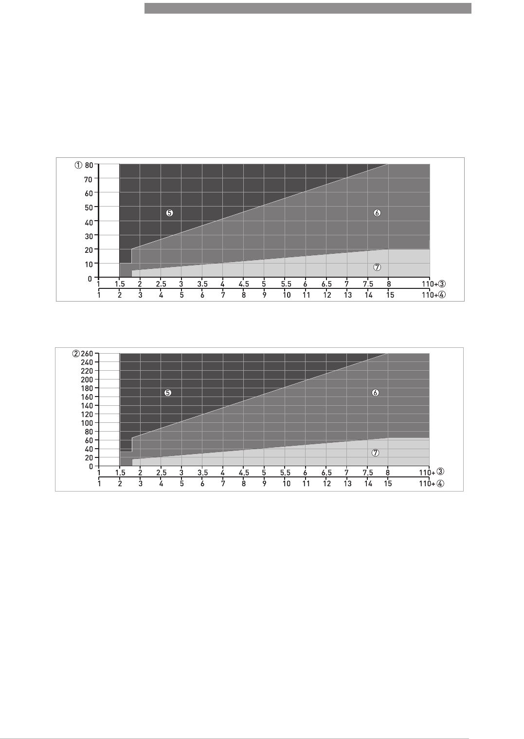
8
TECHNICAL DATA
100
OPTIWAVE 7400-24 C
www.krohne.com 12/2015 - 4003518001 - MA OPTIWAVE7400-24-R01-en
8.4 Antenna selection
The graphs below show which antenna to select for the application based on:
•D, the measuring range,
•ε
r
, is the dielectric constant of the product being measured
Figure 8-4: Selection of antenna for liquid applications (graph of distance in m against ε
r
)
Figure 8-5: Selection of antenna for liquid applications (graph of distance in ft against ε
r
)
1 Distance, D [m]
2 Distance, D [ft]
3 Dielectric constant (ε
r
) range for storage/still well applications
4 Dielectric constant (ε
r
) range for process/agitator applications
5 DN80, DN100, DN150 or DN200 Horn antenna with a still well, or DN150 or DN200 Horn antenna without a still well
6 DN80, DN100, DN150 or DN200 Horn antenna with or without a still well, or DN80 or DN150 Drop antenna without a
still well
7 DN40, DN50, DN80, DN100, DN150 or DN200 Horn antenna with or without a still well, DN80 or DN150 Drop antenna
without a still well or Hygienic antenna
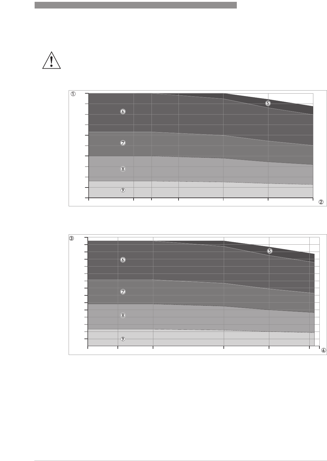
TECHNICAL DATA
8
101
OPTIWAVE 7400-24 C
www.krohne.com12/2015 - 4003518001 - MA OPTIWAVE7400-24-R01-en
8.5 Guidelines for maximum operating pressure
WARNING!
Make sure that the devices are used within their operating limits.
Figure 8-6: Pressure / temperature de-rating (EN 1092-1), flange and threaded connection, in °C and barg
Figure 8-7: Pressure / temperature de-rating (EN 1092-1), flange and threaded connections, in °F and psig
-50 0 50 100 150 200
0
10
20
30
40
50
60
70
80
90
100
20
-60 0 68 210 300 380 400
0
100
200
300
400
500
600
700
800
900
1000
1100
1200
1300
1400
1500

8
TECHNICAL DATA
102
OPTIWAVE 7400-24 C
www.krohne.com 12/2015 - 4003518001 - MA OPTIWAVE7400-24-R01-en
INFORMATION!
CRN certification
CRN certificationCRN certification
CRN certification
There is a CRN certification option for devices with process connections that agree with ASME
standards. This certification is necessary for all devices that are installed on a pressure vessel
and used in Canada.
TECHNICAL DATA
8
103
OPTIWAVE 7400-24 C
www.krohne.com12/2015 - 4003518001 - MA OPTIWAVE7400-24-R01-en
8.6 Dimensions and weights
Dimensions and weights in mm and kg
Dimensions and weights in inches and lb
DN40/1.5¨ Metallic Horn (machined) antenna versions
Figure 8-8: DN40 or 1.5¨ horn antenna versions
1 DN40/1.5¨ horn antenna with G 1½ or 1½NPT thread connection
2 DN40/1.5¨ horn antenna with flange connection
INFORMATION!
•
Cable glands are delivered on demand with non-Ex, Ex i- and Ex d-approved devices.
•
The diameter of the outer sheath of the cable must be 7
…
12 mm or 0.28
…
0.47
¨
.
•
Cable glands for cFMus-approved devices must be supplied by the customer.
•
A weather protection cover is available as an accessory with all devices.
Dimensions [mm] Weights [kg]
a b c d e f h Øi
Thread
connection
??? 1 ??? ??? ??? ??? 32 126 2 39 ???
Flange
connection
??? 1 ??? ??? ??? 3 ??? 3 45 3 96 2 39 ??...??
1If fitted with standard cable glands
2Additional antenna extensions of Ø39 × length 105 mm are available
3With ¼NPTF purge connection option: add 17 mm to this dimension. With distance piece option: add 71 mm to this dimension.
Dimensions [inches] Weights [lb]
a b c d e f h Øi
Thread
connection
??? 1 ??? ??? ??? ??? 1.3 4.9 2 1.5 ???
Flange
connection
??? 1 ??? ??? ??? 3 ??? 3 1.8 3 3.8 2 1.5 ??...??
1If fitted with standard cable glands
2Additional antenna extensions of Ø1.5 × length 4.1¨ are available
3With ¼NPTF purge connection option: add 0.7¨ to this dimension. With distance piece option: add 2.8¨ to this dimension.

8
TECHNICAL DATA
104
OPTIWAVE 7400-24 C
www.krohne.com 12/2015 - 4003518001 - MA OPTIWAVE7400-24-R01-en
DN50/2¨ Metallic Horn (machined) horn antenna versions
Figure 8-9: DN50/2¨ horn antenna versions
1 DN50/2¨ horn antenna with G 1½ or 1½NPT thread connection
2 DN50/2¨ horn antenna with flange connection
INFORMATION!
•
Cable glands are delivered on demand with non-Ex, Ex i- and Ex d-approved devices.
•
The diameter of the outer sheath of the cable must be 7
…
12 mm or 0.28
…
0.47
¨
.
•
Cable glands for cFMus-approved devices must be supplied by the customer.
•
A weather protection cover is available as an accessory with all devices.

TECHNICAL DATA
8
105
OPTIWAVE 7400-24 C
www.krohne.com12/2015 - 4003518001 - MA OPTIWAVE7400-24-R01-en
Dimensions and weights in mm and kg
Dimensions and weights in inches and lb
Dimensions [mm] Weight [kg]
a b c d e f h Øi
Thread
connection
??? 1 ??? ??? ??? ??? 32 136 2 43 ???
Flange
connection
??? 1 ??? ??? ??? 3 ??? 3 45 3 107 2 43 ??...??
1If fitted with standard cable glands
2Additional antenna extensions of Ø39 × length 105 mm are available
3With ¼NPTF purge connection option: add 17 mm to this dimension. With distance piece option: add 71 mm to this dimension.
Dimensions [inches] Weights [lb]
a b c d e f h Øi
Thread
connection
??? 1 ??? ??? ??? ??? 1.3 5.3 2 1.7 ???
Flange
connection
??? 1 ??? ??? ??? 3 ??? 3 1.8 3 4.2 2 1.7 ??...??
1If fitted with standard cable glands
2Additional antenna extensions of Ø1.5 × length 4.1¨ are available
3With ¼NPTF purge connection option: add 0.7¨ to this dimension. With distance piece option: add 2.8¨ to this dimension.

8
TECHNICAL DATA
106
OPTIWAVE 7400-24 C
www.krohne.com 12/2015 - 4003518001 - MA OPTIWAVE7400-24-R01-en
Metallic Horn (sheet metal) antenna versions
Figure 8-10: DN65/2.5¨, DN80/3¨, DN100/4¨, DN150/6¨ and DN200/8¨ Metallic Horn (sheet metal) antenna versions
1 Metallic Horn antenna (DN65/2.5¨, DN80/3¨, DN100/4¨, DN150/6¨ or DN200/8¨) with G 1½ or 1½NPT thread connection
2 Sheet metal horn antenna (DN65/2.5¨, DN80/3¨, DN100/4¨, DN150/6¨ or DN200/8¨) with flange connection
3 Antenna purging system option (supplied with ¼NPTF connection)
INFORMATION!
•
Cable glands are delivered on demand with non-Ex, Ex i- and Ex d-approved devices.
•
The diameter of the outer sheath of the cable must be 7
…
12 mm or 0.28
…
0.47
¨
.
•
Cable glands for cFMus-approved devices must be supplied by the customer.
•
A weather protection cover is available as an accessory with all devices.
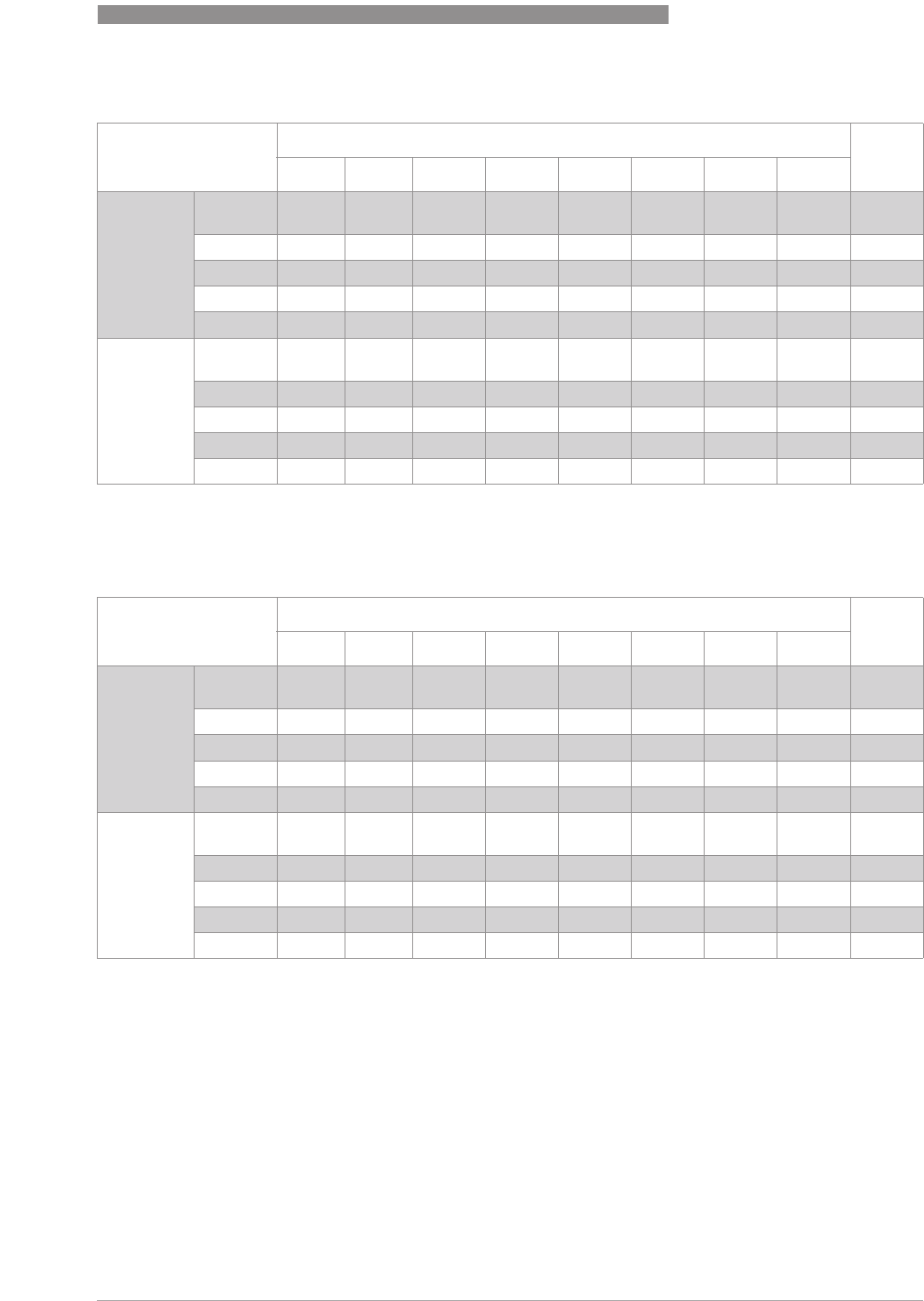
TECHNICAL DATA
8
107
OPTIWAVE 7400-24 C
www.krohne.com12/2015 - 4003518001 - MA OPTIWAVE7400-24-R01-en
Dimensions and weights in mm and kg
Dimensions and weights in inches and lb
Dimensions [mm] Weights
[kg]
a b c d e f h Øi
Thread
connection
DN65/2.5
¨
??? 1 ??? ??? ??? ??? ??? ??? 2 ??
DN80/3¨??? 1 ??? ??? ??? ??? 33 249 2 75 ??
DN100/4¨??? 1 ??? ??? ??? ??? 33 318 2 95 ??
DN150/6¨??? 1 ??? ??? ??? ??? 33 486 2 144 ??
DN200/8¨??? 1 ??? ??? ??? ??? 33 644 2 190 ??
Flange
connection
DN65/2.5
¨
??? 1 ??? ??? ??? 3 ??? 3 45 3 ??? 2 ?? ??
DN80/3¨??? 1 ??? 201 ??? 3 ??? 3 45 3 221 2 75 ??
DN100/4¨??? 1 ??? 201 ??? 3 ??? 3 45 3 290 2 95 ??
DN150/6¨??? 1 ??? 201 ??? 3 ??? 3 45 3 458 2 144 ??
DN200/8¨??? 1 ??? ??? ??? 3 ??? 3 45 3 616 2 190 ??
1If fitted with standard cable glands
2Additional antenna extensions of Ø39 × length 105 mm are available
3With ¼NPTF purge connection option: add 17 mm to this dimension. With distance piece option: add 71 mm to this dimension.
Dimensions [inches] Weights
[lb]
a b c d e f h Øi
Thread
connection
DN65/2.5
¨
??? 1 ??? ??? ??? ??? ??? ??? 2 ??? ???
DN80/3¨??? 1 ??? ??? ??? ??? 1.3 9.8 2 3.0 ???
DN100/4¨??? 1 ??? ??? ??? ??? 1.3 12.5 2 3.7 ???
DN150/6¨??? 1 ??? ??? ??? ??? 1.3 19.1 2 5.7 ???
DN200/8¨??? 1 ??? ??? ??? ??? 1.3 25.4 2 7.5 ???
Flange
connection
DN65/2.5
¨
??? 1 ??? ??? ??? 3 ??? 3 1.8 3 ??? 2 ??? ???
DN80/3¨??? 1 ??? ??? ??? 3 ??? 3 1.8 3 8.7 2 3.0 ???
DN100/4¨??? 1 ??? ??? ??? 3 ??? 3 1.8 3 11.4 2 3.7 ???
DN150/6¨??? 1 ??? ??? ??? 3 ??? 3 1.8 3 18.0 2 5.7 ???
DN200/8¨??? 1 ??? ??? ??? 3 ??? 3 1.8 3 24.3 2 7.5 ???
1If fitted with standard cable glands
2Additional antenna extensions of Ø1.5 × length 4.1¨ are available
3With ¼NPTF purge connection option: add 0.7¨ to this dimension. With distance piece option: add 2.8¨ to this dimension.
8
TECHNICAL DATA
108
OPTIWAVE 7400-24 C
www.krohne.com 12/2015 - 4003518001 - MA OPTIWAVE7400-24-R01-en
DN80/3¨ Drop antenna versions
Figure 8-11: DN80/3¨ Drop antenna versions
1 DN80/3¨ Drop antenna with G 1½ or 1½NPT thread connection
2 DN80/3¨ Drop antenna with flange connection
3 DN80/3¨ Drop antenna with PP, PTFE or PEEK flange plate protection option
INFORMATION!
•
Cable glands are delivered on demand with non-Ex, Ex i- and Ex d-approved devices.
•
The diameter of the outer sheath of the cable must be 7
…
12 mm or 0.28
…
0.47
¨
.
•
Cable glands for cFMus-approved devices must be supplied by the customer.
•
A weather protection cover is available as an accessory with all devices.

TECHNICAL DATA
8
109
OPTIWAVE 7400-24 C
www.krohne.com12/2015 - 4003518001 - MA OPTIWAVE7400-24-R01-en
Dimensions and weights in mm and kg
Dimensions and weights in inches and lb
Dimensions [mm] Weights [kg]
a b c d e f h Øi j
Thread connection ???
1
??? ??? ??? ??? 33 165
2
74 –??…??
Flange connection ???
1
??? ??? ??? ??? 45 137
2
74 –??…??
Flange connection with flange
plate protection option
???
1
??? ??? ??? ??? 45 137 74 39 ??…??
1If fitted with standard cable glands
2Additional antenna extensions of Ø39 × length 105 mm are available. Do not attach more than 5 antenna extensions.
Dimensions [inches] Weights [lb]
a b c d e f h Øi j
Thread connection ???
1
??? ??? ??? ??? 1.3 6.5 2 2.9 –??…??
Flange connection ???
1
??? ??? ??? ??? 1.8 5.4 2 2.9 –??…??
Flange connection with flange
plate protection option
???
1
??? ??? ??? ??? 1.8 5.4 2.9 1.5 ??…??
1If fitted with standard cable glands
2Additional antenna extensions of Ø1.5 × length 4.1¨ available. Do not attach more than 5 antenna extensions.

8
TECHNICAL DATA
110
OPTIWAVE 7400-24 C
www.krohne.com 12/2015 - 4003518001 - MA OPTIWAVE7400-24-R01-en
DN150/6¨ Drop antenna versions (PP or PEEK material options only)
Figure 8-12: DN150/6¨ Drop antenna versions (PP or PEEK materials option only)
1 DN150/6¨ Drop antenna with flange connection
2 DN150/6¨ Drop antenna with thread connection
3 DN150/6¨ Drop antenna, with flange plate protection option
INFORMATION!
•
Cable glands are delivered on demand with non-Ex, Ex i- and Ex d-approved devices.
•
The diameter of the outer sheath of the cable must be 7
…
12 mm or 0.28
…
0.47
¨
.
•
Cable glands for cFMus-approved devices must be supplied by the customer.
•
A weather protection cover is available as an accessory with all devices.

TECHNICAL DATA
8
111
OPTIWAVE 7400-24 C
www.krohne.com12/2015 - 4003518001 - MA OPTIWAVE7400-24-R01-en
Dimensions and weights in mm and kg
Dimensions and weights in inches and lb
Dimensions [mm] Weights [kg]
a b c d e f h Øi j k
Thread connection ?? 1 ?? ?? ?? ?? 33 242
2
144 – – ??
Flange connection ?? 1 ?? ?? ?? ?? 45 214
2
144 – – ??…??
Flange connection with flange
plate protection option
?? 1 ?? ?? ?? ?? 45 214 144 39 – –
1If fitted with standard cable glands
2Additional antenna extensions of Ø39 × length 105 mm are available. Do not attach more than 5 antenna extensions.
Dimensions [inches] Weights [lb]
a b c d e f h Øi j k
Thread connection ?? 1 ?? ?? ?? ?? 1.3 9.5
2
5.7 – – ??
Flange connection ?? 1 ?? ?? ?? ?? 1.8 8.4
2
5.7 – – ??…??
Flange connection with flange
plate protection option
?? 1 ?? ?? ?? ?? 1.8 8.4 5.7 1.5 – –
1If fitted with standard cable glands
2Additional antenna extensions of Ø1.5 × length 4.1¨ are available. Do not attach more than 5 antenna extensions.
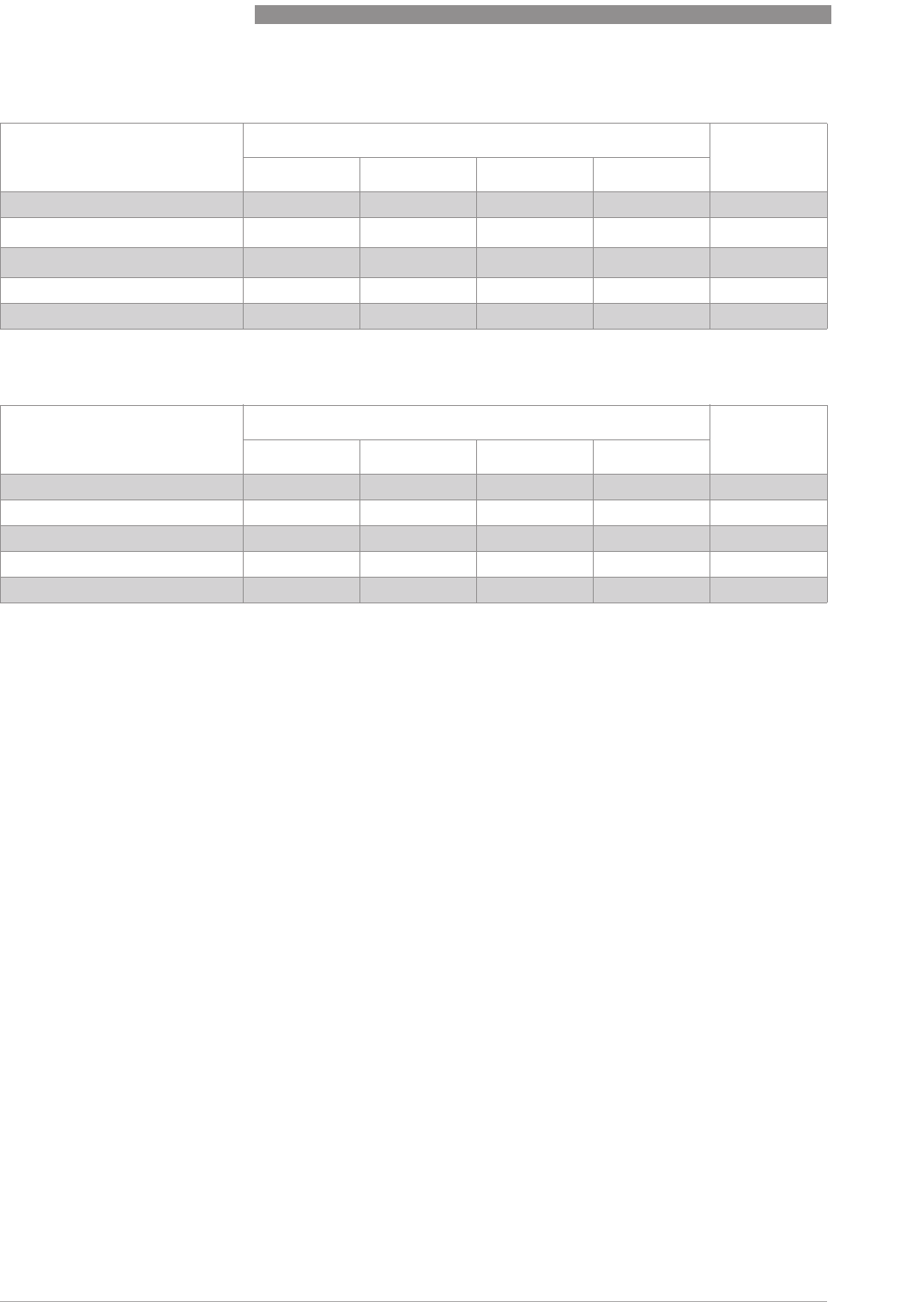
8
TECHNICAL DATA
112
OPTIWAVE 7400-24 C
www.krohne.com 12/2015 - 4003518001 - MA OPTIWAVE7400-24-R01-en
Dimensions and weights in mm and kg
Dimensions and weights in inches and lb
Dimensions [mm] Weights [kg]
a b d h
DIN 11851 connection ??? 1 ??? ??? 8???
Tri-Clamp
®
connection ??? 1 ??? ??? 8???
Neumo BioControl
®
connection ??? 1 ??? ??? 25 ???
SMS connection ??? 1 ??? ??? 8???
VARIVENT® connection ??? 1 ??? ??? 25 ???
1If fitted with standard cable glands
Dimensions [inches] Weights [lb]
a b d h
DIN 11851 connection ??? 1 ??? 1 ??? 1 0.3 ??? 1
Tri-Clamp® connection ??? 1 ??? 1 ??? 1 0.3 ??? 1
Neumo BioControl® connection ??? 1 ??? 1 ??? 1 1.0 ??? 1
SMS connection ??? 1 ??? 1 ??? 1 0.3 ??? 1
VARIVENT® connection ??? 1 ??? 1 ??? 1 1.0 ??? 1
1If fitted with standard cable glands

TECHNICAL DATA
8
113
OPTIWAVE 7400-24 C
www.krohne.com12/2015 - 4003518001 - MA OPTIWAVE7400-24-R01-en
Type of housing Weights
Aluminium housing Stainless steel housing
[kg] [lb] [kg] [lb]
Compact ?? ?? ?? ??
Remote converter 1 ?? ?? ?? ??
Antenna housing 2 ?? ?? ?? ??
1The remote version of the device has a "remote converter" and a "probe housing". For more data, refer to "Housing dimensions" at the
start of this section.
2The remote version of the device has a "remote converter" and a "antenna housing". For more data, refer to "Housing dimensions" at
the start of this section.
Type of housing Weights
Aluminium housing Stainless steel housing
[kg] [lb] [kg] [lb]
Compact ?? ?? ?? ??
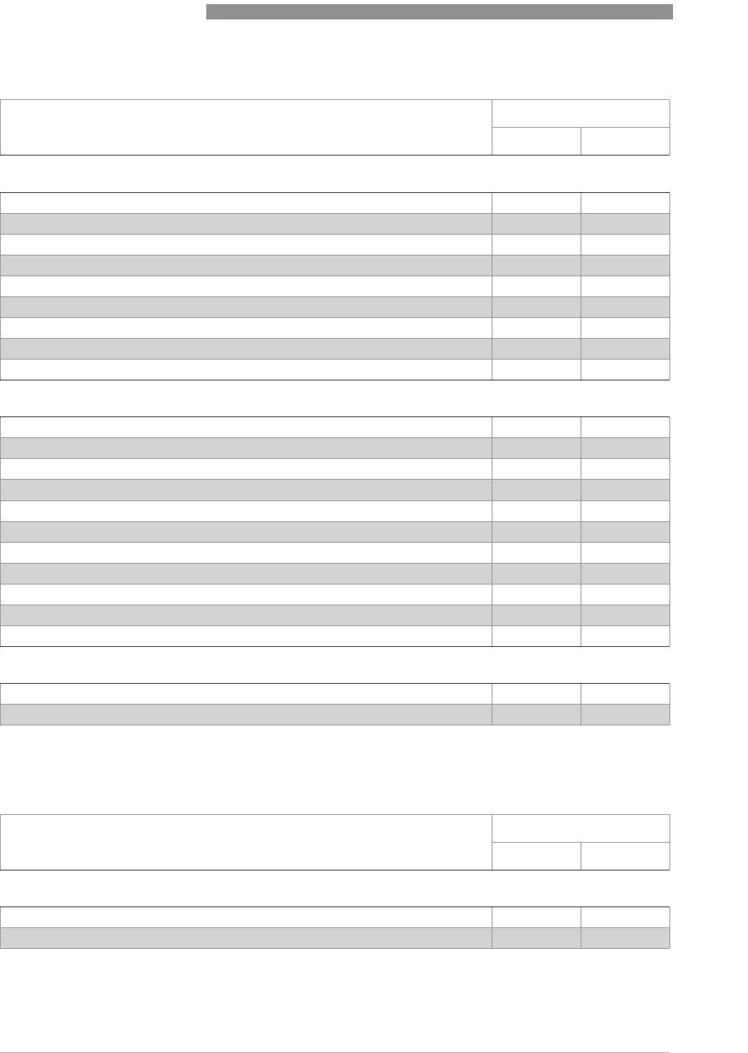
8
TECHNICAL DATA
114
OPTIWAVE 7400-24 C
www.krohne.com 12/2015 - 4003518001 - MA OPTIWAVE7400-24-R01-en
Antenna option weights
Antenna options Min./Max. weights
[kg] [lb]
Standard options, without converter
Standard options, without converterStandard options, without converter
Standard options, without converter
DN40 / 1.5¨ Metallic Horn antenna with flange connection, standard length ??...?? ??...??
DN50 / 2¨ Metallic Horn antenna with flange connection, standard length ??...?? ??...??
DN65 / 2.5¨ Metallic Horn antenna with flange connection, standard length ??...?? ??...??
DN100 / 4¨ Metallic Horn antenna with flange connection, standard length 5.6...37.1 12.3...81.8
DN100 / 4¨ Metallic Horn antenna with flange connection, standard length 9.1...37.2 20.1...82
DN150 / 6¨ Metallic Horn antenna with flange connection, standard length 13.6...37.5 30...82.7
DN200 / 8¨ Metallic Horn antenna with flange connection, standard length 14.0..37.8 30.9...83.3
DN80 Drop antenna with thread connection, standard length ??...?? ??...??
DN150 Drop antenna with thread connection, standard length ??...?? ??...??
Antenna extension options
Antenna extension optionsAntenna extension options
Antenna extension options
Straight extension, length 105 mm 1 +?? +??
Straight extension, length 210 mm 1 +?? +??
Straight extension, length 315 mm 1 +?? +??
Straight extension, length 420 mm 1 +?? +??
Straight extension, length 525 mm 1 +?? +??
Straight extension, length 630 mm 2 +?? +??
Straight extension, length 735 mm 2 +?? +??
Straight extension, length 840 mm 2 +?? +??
Straight extension, length 945 mm 2 +?? +??
Straight extension, length 1050 mm 2 +?? +??
"L" (right-angle) extension 2 +?? +??
Other options
Other optionsOther options
Other options
HT extension 3 +?? +??
Flange plate option +?? +??
1This option is for Metallic Horn and Drop antenna options
2This option is for Metallic Horn antenna options
3This component is only for the Metallic Horn and Wave Guide antennas. It is attached between the signal converter and the flange if the
process connection temperature is +150...+250°C / +302...+482°F.
Antenna options Min./Max. weights
[kg] [lb]
Standard options, without converter
Standard options, without converterStandard options, without converter
Standard options, without converter
DN50 / 2¨ Hygienic antenna with clamp connection ??...?? ??...??
DN50 / 2¨ Hygienic antenna with thread connection ??...?? ??...??
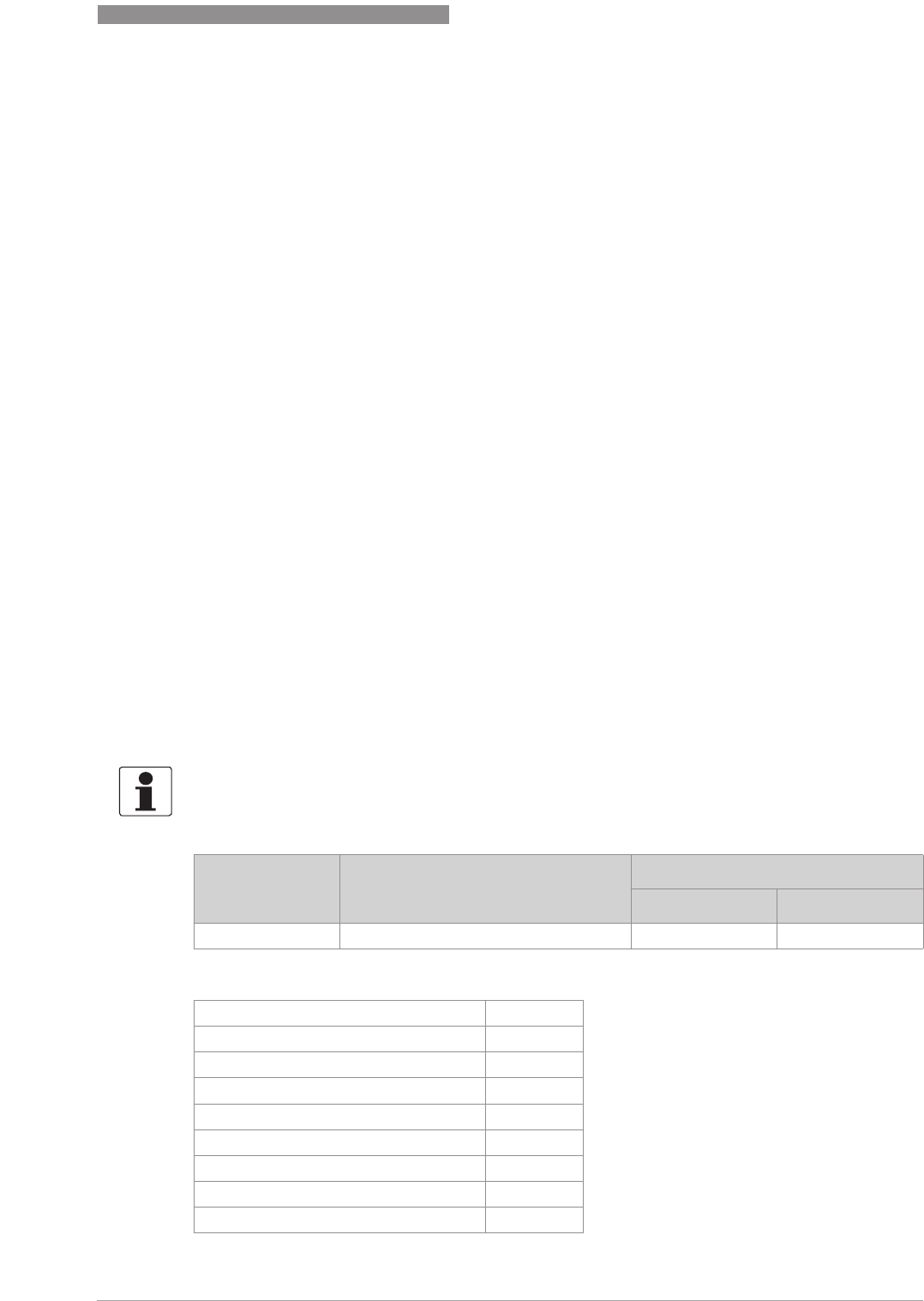
DESCRIPTION OF HART INTERFACE
9
115
OPTIWAVE 7400-24 C
www.krohne.com12/2015 - 4003518001 - MA OPTIWAVE7400-24-R01-en
9.1 General description
The HART® Protocol is an open digital communication protocol for industry. It is free to use by
anyone. It is included in the software embedded in signal converters of HART-compatible
devices.
There are 2 classes of devices which support the HART® Protocol: operating devices and field
devices. There are 2 classes of operating devices (Master): PC-supported workstations (Primary
Master) and manual control units (Secondary Master). These can be used in control centres and
other locations. HART® field devices include sensors, converters and actuators. Field devices
include 2-wire and 4-wire devices, and also intrinsically-safe versions for use in hazardous
areas.
There are 2 primary operation modes for HART-compatible devices: point-to-point mode and
multi-drop mode.
If the device is used in point-to-point mode, the HART® Protocol uses the Bell 202 Frequency
Shift Keying (FSK) standard to put a digital signal on top of the 4...20 mA signal. The connected
device sends and receives digital signals that agree with the HART® Protocol, and sends analog
signals at the same time. Only 1 device can be connected to the signal cable.
If the device is used in multi-drop mode, the network only uses a digital signal that agrees with
the HART® Protocol. The loop current is set to 4 mA. You can connect a maximum of 15 devices
to the signal cable.
An FSK or HART® modem is included in field devices and manual control units. It is necessary to
have an external modem for PC-supported workstations. The external modem is connected to
the serial interface.
9.2 Software history
HART® identification codes and revision numbers
INFORMATION!
In the table below, "x" is a placeholder for possible multi-digit alphanumeric combinations,
depending on the available version.
Release date Devices HART®
Device Revision DD Revision
2008-03 All revisions 1 2
Manufacturer ID: 0x45
Device: 0xE5
Device Revision: 1
DD Revision 2
HART® Universal Revision: 7
FC 375/475 system SW.Rev.: ≥1.8
AMS version: ≥7.0
PDM version: –
FDT version: ≥1.2

9
DESCRIPTION OF HART INTERFACE
116
OPTIWAVE 7400-24 C
www.krohne.com 12/2015 - 4003518001 - MA OPTIWAVE7400-24-R01-en
9.3 Connection variants
The signal converter is a 2-wire device with 4...20 mA current output and HART
®
interface.
•Multi-Drop Mode is supported
Multi-Drop Mode is supportedMulti-Drop Mode is supported
Multi-Drop Mode is supported
In a Multi-Drop communication system, more than 1 device is connected to a common
transmission cable.
•Burst Mode is not supported
Burst Mode is not supportedBurst Mode is not supported
Burst Mode is not supported
There are two ways of using the HART® communication:
•as Point-to-Point connection and
•as Multi-Drop connection with 2-wire connection.
9.3.1 Point-to-Point connection - analogue / digital mode
Point-to-Point connection between the signal converter and the HART® Master.
The current output of the device is passive.
Also.
9.3.2 Multi-Drop connection (2-wire connection)
For an illustration of multi-drop networks.
9.4 HART® device variables
The HART® dynamic variables PV (Primary Variable), SV (Secondary Variable), TV (Third Variable)
and QV (Fourth Variable) can be assigned to any of the device variables.
The HART® dynamic variable PV is always connected to the HART® current output which is, for
example, assigned to level measurement.
9.5 Field Communicator 475 (FC 475)
The Field Communicator is a hand terminal from Emerson Process Management that is
designed to configure HART® and Foundation Fieldbus devices. Device Descriptions (DDs) are
used to integrate different devices into the Field Communicator.
9.5.1 Installation
System and software requirements for the Field Communicator
•System card that includes the "Easy Upgrade Option"
•Field Communicator Easy Upgrade Programming Utility
•HART
®
Device Description file
CAUTION!
The Field Communicator cannot be used to correctly configure, operate or read data from the
device unless the Device Description (DD) file is installed.

DESCRIPTION OF HART INTERFACE
9
117
OPTIWAVE 7400-24 C
www.krohne.com12/2015 - 4003518001 - MA OPTIWAVE7400-24-R01-en
For more data, refer to the Field Communicator User’s Manual.
9.5.2 Operation
The Field Communicator and the device's local display use almost the same procedures to
operate the signal converter. The online help for each menu item refers to the function number
given to each menu item on the local device display. Protection of settings is the same as on the
device's local display.
The Field Communicator always saves a complete configuration for communication with AMS.
For more data, refer to
HART
® menu tree for Basic-DD on page 118.
9.6 Asset Management Solutions (AMS)
The Asset Management Solutions Device Manager (AMS) is a PC program from Emerson
Process Management which is designed to configure and manage HART
®
, PROFIBUS and
Foundation-Fieldbus devices. Device Descriptions (DDs) are used to integrate different devices
into the AMS.
9.6.1 Installation
Please read the README.TXT file in the Installation Kit.
If the Device Description has not been installed at this time, install the Installation Kit HART
®
AMS. This .EXE file is given on the DVD-ROM supplied with the device. You can also download the
file from our website.
For installation data, refer to the "AMS Intelligent Device Manager Books Online" section "Basic
AMS Functionality > Device Configurations > Installing Device Types > Procedures > Install
device types from media".
9.6.2 Operation
9.6.3 Parameter for the basic configuration
Due to AMS requirements and conventions, there are differences when operating the signal
converter with AMS and operating using the local keyboard. The service menu parameters are
not supported and simulation is only possible for current outputs. The online help for each
parameter contains its function number as a reference to the local device display.
INFORMATION!
The Field Communicator will not give you access to the service menu. A simulation is only
possible for current outputs.
INFORMATION!
For more data, refer to HART
®
menu tree for AMS on page 119
.

9
DESCRIPTION OF HART INTERFACE
118
OPTIWAVE 7400-24 C
www.krohne.com 12/2015 - 4003518001 - MA OPTIWAVE7400-24-R01-en
9.7 Field Device Tool / Device Type Manager (FDT / DTM)
9.7.1 Installation
Before you operate the device, the Device Type Manager (Device DTM) must be installed in the
Field Device Tool Container. This .msi file is given on the DVD-ROM supplied with the device. You
can also download the file from our website. For installation and configuration data, refer to the
documentation that is supplied with the Device DTM on the DVD-ROM or in the "Downloads"
section of the website.
9.7.2 Operation
The DTM and the device's local display use almost the same procedures to operate the signal
converter. For more data, refer to
Operation
on page 56.
9.8 HART
®
menu tree for Basic-DD
Abbreviations of the following tables:
•
Opt
Optional, depending on device version and configuration
•
Rd
Read only
9.8.1 Overview Basic-DD menu tree (positions in menu tree)
9.8.2 Basic-DD menu tree (details for settings)
1Measurements 1Measurements
2Output
2Configuration and Test 1Info. 1 Identification
2Output
2Supervisor 1Test
2 Basic Parameters
3Signal Out
4 Application
5Display
6Conversion Table
7 Reset
3Diag/Service 1 Status 1 Standard Status
2 Device-specific Status
4 Access Rights 1 Access level
2Method Login
3Method entry Code
5HART variables
1Measurements
1Measurements 1 Level value
Rd
/ 2 Distance value
Rd
/ 3 Volume value
Rd
/ 4 Ullage value
Rd
/ 5 Reflection
value
Rd

DESCRIPTION OF HART INTERFACE
9
119
OPTIWAVE 7400-24 C
www.krohne.com12/2015 - 4003518001 - MA OPTIWAVE7400-24-R01-en
9.9 HART
®
menu tree for AMS
Abbreviations of the following tables:
•
Opt
Optional, depending on device version and configuration
•
Rd
Read only
2 Inputs/Outputs 1PV
Rd
/ 2 PV Loop Current
Rd
/ 3 PV % rnge
Rd
2Configuration and Test
1Info. 1 Identification 1 Serial Number
Rd
/ 2 Converter Firmware Version
Rd
/ 3 Sensor
Firmware Version
Rd
/ 4 HMI Firmware Version
Rd
2Output 1Function I
Rd
/ 2 Output Range
Rd
/ 3 PV URV
Rd
/ 4 PV LRV
Rd
/
5 Output Error Delay
Rd
2Supervisor 1Test 1Test I
2 Basis Parameters 1 Tank Height / 2 Blocking Distance / 3 Time Constant / 4 Pipe
Enabled / 5 Pipe Diameter / 6 Pipe Height / 7 Antenna Extension /
8 Antenna Type / 9 Distance Piece / 15 Length Unit (HART) /
16 Volume Unit (HART)
3Signal Out 1 Function I / 2 PV LRV / 3 PV URV / 4 Output Range / 5 Output
Error Delay / 6 Current Ouput Calibration
Cust
4 Application 1Tank Type/ 2Tracking Velocity/ 3Esilon R Product/
4Measuring Mode/ 5Overfill Detection/ 6Multiple Reflection/
7 Empty Spectrum / 8 Record Empty Spectrum
5Display 1 Language / 2 Display Length Unit / 3 Display Volume Unit
6Conversion Table 1 Input table / 2 Delete table
7Reset 1 Warm start / 2 Factory reset / 3 Reset Configuration Changed
flag
3Diag/Service
1Status 1 Standard status 1 Device status
Rd
/ 2 Write protect
Rd
2 Device-specific
status 1 Device failures 1 Error
Rd
/ 2 Error
Rd
/ 3 Error
Rd
2 Device warning maintenance
required 1Warning
Rd
3 Device warning out of
specification 1Warning
Rd
4Info 1Info
Rd
4Access Rights
1 Access Level (Access Not Granted)
2Method Login 1 No Access (Log Out) / 2 Supervisor (Normal User) / 3 Service
3Method Entry Code
5HART variables
1 Poll addr / 2 Tag / 3 Hardware rev
Rd
/ 4 Software rev
Rd
/ 5Descriptor/ 6Date/
7Message/ 8Manufacturer
Rd
/ 9 Model
Rd
/ Dev id
Rd
/ Universal id
Rd
/ Fld dev rev
Rd
/ Num
req preams
Rd
/ Num resp preams
Rd
/ Write protect
Rd
/ Production number
Rd
/ Final
asmbly num
Rd
/ PV is / SV is / TV is / QV is
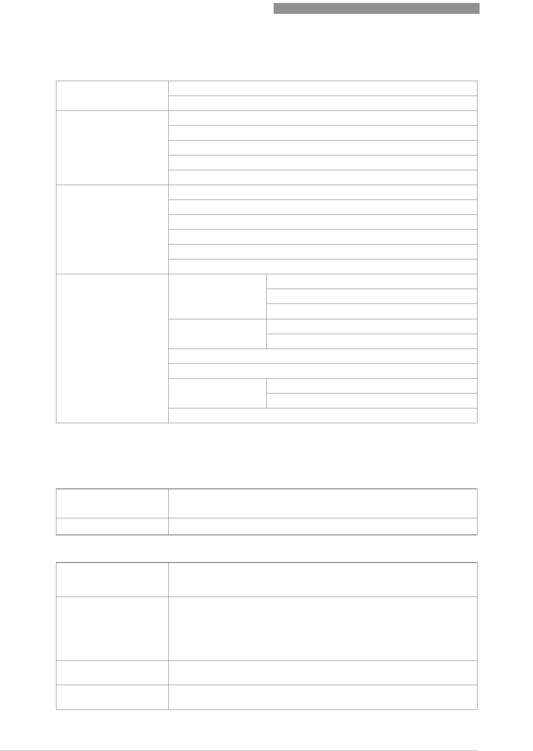
9
DESCRIPTION OF HART INTERFACE
120
OPTIWAVE 7400-24 C
www.krohne.com 12/2015 - 4003518001 - MA OPTIWAVE7400-24-R01-en
9.9.1 Overview AMS menu tree (positions in menu tree)
9.9.2 AMS menu tree (details for settings)
Process variables Measurements
Analog Output
Device Diagnostics Overview
Fatal Errors
Warnings (Maintenance required)
Warnings (Out of specifications)
Warnings (Function check)
Methods Access Right
Tests
Calibrate
Empty Spectrum
Conversion Table
Master reset
Configure / Setup Basic Setup Basic Parameters
Local Display
Application
Analog Output Output Functions
Output 1
Units
Device
HART ID
-
Conversion table
Process Variables
Measurements Level
Rd
/ Distance
Rd
/ Volume/Mass/Flow
Rd
/ Ullage Volume/Mass/Flow
Rd
/
Reflection
Rd
Primary Output Function I / Loop current
Rd
/ PV Percent of Range
Rd
Device Diagnostics
Overview Primary variable out of limits / Non-primary variable out of limits / Primary
variable analog output saturated / Primary variable analog output fixed / Cold
Start / Configuration changed / Field device malfunction
Fatal Errors (Failure) Converter EEPROM error / Converter RAM error / Converter ROM error /
Sensor EEPROM error / Sensor RAM error / Sensor ROM error / Current
output drift / Sensor Microwave error / Converter Voltage error / Sensor
Voltage error / Internal Comm. error / Temperat. out of range / Sensor not
compatible / Sensor no signal / Sensor processing failure / Peak lost error /
Overfill error
Warnings (Maintenance
required)
Empty spectrum invalid / Signal weak / Signal strong / Bad Measurement
Quality / Temperature < -35°C / Temperature > +75°C
Warnings (Out of
specification)
Peak lost / Overfill / Temperature out of range

DESCRIPTION OF HART INTERFACE
9
121
OPTIWAVE 7400-24 C
www.krohne.com12/2015 - 4003518001 - MA OPTIWAVE7400-24-R01-en
Warnings (Function check) Local operation on the device
Information Spectrum quality bad / Peak lost in tank bottom / Temperature out of range
for HMI
Methods
Acess right Log In/Log Out / Password Yes/No
Tests Test Output I
Calibrate D/A Trim
Empty Spectrum Empty Spec. Rec.
Conversion Table Input table / Delete table
Reset Restart Device / Reset Factory / Rst Conf. Chged flag
Configure / Setup
Basic Setup Basic Parameters Tank Height / Blocking Distance / Time Constant /
Stillwell Enabled / Stillwell Diameter / Stillwell
Height / Antenna Extension / Antenna Type /
Distance Piece / Tag
Local Display Display length unit / Display volume unit / Language
Application Tank Type / Tracking velocity / Epsilon R product /
Measuring Mode / Overfill Detection / Multiple
Reflection / Empty Spectrum On/Off
Analog Output Output Functions Function I / SV / TV / QV
Output 1 Output Range / Output Error Delay / LRV / URV
Units Length unit (HART) / Volume unit (HART) / Time constant
Device Model / Manufacturer / Fld dev rev / Software rev / Write protect / Interface
option
Rd
/ Descriptor / Message / Date / Serial number / Converter firmware
number / Sensor Firmware number / HMI Firmware number
HART ID Tag / Polling address / Device ID
Universal revision / Fld dev rev Num / Num request
preams
Conversion table Number of points / Length unit
Rd
/ Conversion unit
Rd
/ Points (1...30 level-
conversion pairs)

10
APPENDIX
122
OPTIWAVE 7400-24 C
www.krohne.com 12/2015 - 4003518001 - MA OPTIWAVE7400-24-R01-en
10.1 Order code
Make a selection from each column to get the full order code. The characters of the order code
highlighted in light grey describe the standard.
VF74 4OPTIFLEX 7400 C 24 GHz Non-contact Radar (FMCW) level meter for liquids
OPTIFLEX 7400 C 24 GHz Non-contact Radar (FMCW) level meter for liquidsOPTIFLEX 7400 C 24 GHz Non-contact Radar (FMCW) level meter for liquids
OPTIFLEX 7400 C 24 GHz Non-contact Radar (FMCW) level meter for liquids
Converter version (Housing material
Converter version (Housing material Converter version (Housing material
Converter version (Housing material – Degrees of protection [IP code])
Degrees of protection [IP code]) Degrees of protection [IP code])
Degrees of protection [IP code])
1OPTIWAVE 7400 C: Compact version (Aluminium – IP 66/67)
2OPTIWAVE 7400 C: Compact version (Stainless steel – IP 66/67)
3OPTIWAVE 7400 F: Remote version (converter and antenna housing: Aluminium – IP 66/67)
4OPTIWAVE 7400 F: Remote version (converter and antenna housing: Stainless steel – IP 66/67)
5OPTIWAVE 7400 F: Remote version (converter housing: Aluminium – IP 66/67 + antenna housing:
Stainless steel – IP 66/67)
Approval
ApprovalApproval
Approval
0Without
1ATEX Ex ia IIC T2…T6 + DIP 1
2ATEX Ex d ia IIC T2..T6 + DIP 1
3ATEX Ex ic IIC T2…T6 + DIP 1
6IECEx Ex ia IIC T2…T6 + DIP 1
7IECEx Ex d ia IIC T2…T6 + DIP 1
8IECEx Ex ic IIC T2…T6 + DIP 1
AcFMus IS CL I/II/III, DIV 1, GPS A-G; CL I, Zone 0/20, Ex ia IIC/IIIC T2…T6
BcFMus XP-IS/DIP CL I/II/III, DIV 1, GPS A-G (A not for CAN); CL I, Zone 0/20, Ex d/tb IIC/IIIC T2…T6
CcFMus NI CL I/II/III, DIV 2, GPS A-G; CL I, Zone 2, Ex nA IIC T2...T6
LNEPSI Ex ia IIC T2 ~ T6 + DIP 1
MNEPSI Ex d ia IIC T2 ~ T6 + DIP 1
NNEPSI Ex ic IIC T2 ~ T6 + DIP 1
Other approval
Other approvalOther approval
Other approval
0Without
1SIL 2 – only available with 4…20 mA output
4CRN (Canadian Registration Number)
5CRN + SIL 2 – only available with 4…20 mA output
VF74
VF74VF74
VF74 4Order code (complete this code on the pages that follow)
Order code (complete this code on the pages that follow)Order code (complete this code on the pages that follow)
Order code (complete this code on the pages that follow)

APPENDIX
10
123
OPTIWAVE 7400-24 C
www.krohne.com12/2015 - 4003518001 - MA OPTIWAVE7400-24-R01-en
Process seal (Temperature / Pressure / Material
Process seal (Temperature / Pressure / Material Process seal (Temperature / Pressure / Material
Process seal (Temperature / Pressure / Material – Remarks)
Remarks) Remarks)
Remarks)
0Without
1-40...+150°C (-40…+302°F) / -1...40 barg (-14.5…580 psig) / FKM/FPM
– for Drop antennas (non-Ex) only
2-50...+150°C (-58…+302°F) / -1...40 barg (-14.5…580 psig) / EPDM
– for Drop antennas (non-Ex) only
4-40...+150°C (-40…+302°F) / -1…16 barg (-14.5…232 psig) / PEEK
– for hygienic connections only
6-40...+150°C (-40…+302°F) / -1...40 barg (-14.5…580 psig) / FKM/FPM
– for Horn and Drop antennas
7-50...+150°C (-58…+302°F) / -1...40 barg (-14.5…580 psig) / EPDM
– for Horn and Drop antennas
8-20...+150°C (-4…+302°F) / -1...40 barg (-14.5…580 psig) / Kalrez® 6375
– for Horn and Drop antennas
A-40...+150°C (-40…+302°F) / -1...40 barg (-14.5…580 psig) / FKM/FPM
– Metaglas® dual sealing barrier for Horn and Drop antennas
B-50...+150°C (-58…+302°F) / -1...40 barg (-14.5…580 psig) / EPDM
– Metaglas® dual sealing barrier for Horn and Drop antennas
C-20...+150°C (-4…+302°F) / -1...40 barg (-14.5…580 psig) / Kalrez® 6375
– Metaglas® dual sealing barrier for Horn and Drop antennas
D-40...+200°C (-40…+392°F) / -1...40 barg (-14.5…580 psig) / FKM/FPM
– for Horn and Drop PEEK antennas
E-20...+200°C (-4…+392°F) / -1...40 barg (-14.5…580 psig) / Kalrez® 6375
– for Horn and Drop PEEK antennas
F-40...+200°C (-40…+392°F) / -1...40 barg (-14.5…580 psig) / FKM/FPM
– Metaglas® dual sealing barrier for Horn and Drop PEEK antennas
G-20...+200°C (-4…+392°F) / -1...40 barg (-14.5…580 psig) / Kalrez® 6375
– Metaglas® dual sealing barrier for Horn and Drop PEEK antennas
K-40...+200°C (-40…+392°F) / -1…100 barg (-14.5…1450 psig) / FKM/FPM
– for Horn antennas only
L-50...+150°C (-58…+302°F) / -1…100 barg (-14.5…1450 psig) / EPDM
– for Horn antennas only
M-20...+200°C (-4…+392°F) / -1…100 barg (-14.5…1450 psig) / Kalrez® 6375
– for Horn antennas only
N-40...+200°C (-40…+392°F) / -1…100 barg (-14.5…1450 psig) / FKM/FPM
– Metaglas® dual sealing barrier for Horn antennas only
P-50...+150°C (-58…+302°F) / -1…100 barg (-14.5…1450 psig) / EPDM
– Metaglas® dual sealing barrier for Horn antennas only
R-20...+200°C (-4…+392°F) / -1…100 barg (-14.5…1450 psig) / Kalrez® 6375
– Metaglas® dual sealing barrier for Horn antennas
VF74
VF74VF74
VF74 4Order code (complete this code on the pages that follow)
Order code (complete this code on the pages that follow)Order code (complete this code on the pages that follow)
Order code (complete this code on the pages that follow)

10
APPENDIX
124
OPTIWAVE 7400-24 C
www.krohne.com 12/2015 - 4003518001 - MA OPTIWAVE7400-24-R01-en
Antenna (Antenna type / Material)
Antenna (Antenna type / Material)Antenna (Antenna type / Material)
Antenna (Antenna type / Material)
0Without
1Metallic Horn (machined) DN 40 (1.5¨) / 316 L
2Metallic Horn (machined) DN 50 (2¨) / 316 L
3Metallic Horn (sheet metal) DN 65 (2.5¨) / 316 L
4Metallic Horn (sheet metal) DN 80 (3¨) / 316 L
5Metallic Horn (sheet metal) DN 100 (4¨)/ 316L
6Metallic Horn (sheet metal) DN 150 (6¨)/ 316L
7Metallic Horn (sheet metal) DN 200 (8¨)/ 316L
ADrop DN 80 (3¨)/ PP
BDrop DN 80 (3¨) + flange plate DN 80–100 (3¨ – 4¨)/ PP
CDrop DN 80 (3¨) + flange plate DN 150–200 (6¨ – 8¨)/ PP
DDrop DN 150 (6¨)/ PP
EDrop DN 150 (6¨) + flange plate DN 150–200 (6¨ – 8¨)/ PP
GDrop DN 80 (3¨)/ PTFE
HDrop DN 80 (3¨) + flange face DN 80–100 (3¨ – 4¨)/ PTFE
KDrop DN 80 (3¨) + flange face DN 150–200 (6¨ – 8¨)/ PTFE
MHygienic antenna FDA conform / PEEK
PDrop DN 80 (3¨) / PEEK
RDrop DN 80 (3¨) + flange plate DN 80–100 (3¨ – 4¨) / PEEK
SDrop DN 80 (3¨) + flange plate DN 150–200 (6¨ – 8¨)/ PEEK
TDrop DN 150 (6¨) / PEEK
UDrop DN 150 (6¨) + flange plate DN 150–200 (6¨ – 8¨)/ PEEK
VF74
VF74VF74
VF74 4Order code (complete this code on the pages that follow)
Order code (complete this code on the pages that follow)Order code (complete this code on the pages that follow)
Order code (complete this code on the pages that follow)

APPENDIX
10
125
OPTIWAVE 7400-24 C
www.krohne.com12/2015 - 4003518001 - MA OPTIWAVE7400-24-R01-en
Antenna extension (Extension / Material)
Antenna extension (Extension / Material)Antenna extension (Extension / Material)
Antenna extension (Extension / Material)
0Without
1105 mm (4¨) / 316 L – for devices with Horn or Drop antennas
2210 mm (8¨) / 316 L – for devices with Horn or Drop antennas
3315 mm (12¨) / 316 L – for devices with Horn or Drop antennas
4420 mm (16¨) / 316 L – for devices with Horn or Drop antennas
5525 mm (20¨) / 316 L – for devices with Horn or Drop antennas
6630 mm (24¨) / 316 L – for devices with Horn antennas only
7735 mm (29¨) / 316 L – for devices with Horn antennas only
8840 mm (33¨) / 316 L – for devices with Horn antennas only
A945 mm (37¨) / 316 L – for devices with Horn antennas only
B1050 mm (41¨) / 316 L – for devices with Horn antennas only
D105 mm (4¨) / PP – for devices with a PP Drop antenna + flange plate option only
E210 mm (8¨) / PP – for devices with a PP Drop antenna + flange plate option only
F315 mm (12¨) / PP – for devices with a PP Drop antenna + flange plate option only
G420 mm (16¨) / PP – for devices with a PP Drop antenna + flange plate option only
H525 mm (20¨) / PP – for devices with a PP Drop antenna + flange plate option only
N105 mm (4¨) / PTFE – for devices with a PTFE Drop antenna + flange plate option only
P210 mm (8¨) / PTFE – for devices with a PTFE Drop antenna + flange plate option only
S105 mm (4¨) / PEEK – for devices with a PEEK Drop antenna + flange plate option only
T210 mm (8¨) / PEEK – for devices with a PEEK Drop antenna + flange plate option only
U315 mm (12¨) / PEEK – for devices with a PP Drop antenna + flange plate option only
XL-bend (right angle) extension / 316 L
Process connection (Size / Pressure class / Flange face finish)
Process connection (Size / Pressure class / Flange face finish)Process connection (Size / Pressure class / Flange face finish)
Process connection (Size / Pressure class / Flange face finish)
000Without
Threaded – ISO 228
GPOG1½
Threaded – ASME B1.20.1
G A 0 1½NPT
EN / DIN flanges – EN 1092-1
GG1DN40 PN40 – Type B1
G H 1 DN40 PN63 – Type B1
GK1DN40 PN100 – Type B1
H E 1 DN50 PN16 – Type B1
H G 1 DN50 PN40 – Type B1
HH1 DN50 PN63 – Type B1
H K 1 DN50 PN100 – Type B1
VF74
VF74VF74
VF74 4Order code (complete this code on the pages that follow)
Order code (complete this code on the pages that follow)Order code (complete this code on the pages that follow)
Order code (complete this code on the pages that follow)

10
APPENDIX
126
OPTIWAVE 7400-24 C
www.krohne.com 12/2015 - 4003518001 - MA OPTIWAVE7400-24-R01-en
L E 1 DN80 PN16 – Type B1
L G 1 DN80 PN40 – Type B1
L H 1 DN80 PN63 – Type B1
L K 1 DN80 PN100 – Type B1
M E 1 DN100 PN16 – Type B1
M G 1 DN100 PN40 – Type B1
M H 1 DN100 PN63 – Type B1
M K 1 DN100 PN100 – Type B1
P E 1 DN150 PN16 – Type B1
P G 1 DN150 PN40 – Type B1
P H 1 DN150 PN63 – Type B1
P K 1 DN150 PN100 – Type B1
R E 1 DN200 PN16 – Type B1
R G 1 DN200 PN40 – Type B1
ASME B16.5 / ANSI flanges
G 1 A 1½¨ 150 lb RF (Raised Face)
G 2 A 1½¨ 300 lb RF (Raised Face)
G 3 A 1½¨ 600 lb RF (Raised Face)
G 4 M 1½¨ 900 lb RJ (Ring Joint)
G 5 M 1½¨ 1500 lb RJ (Ring Joint)
H 1 A 2¨ 150 lb RF (Raised Face)
H 2 A 2¨ 300 lb RF (Raised Face)
H 3 A 2¨ 600 lb RF (Raised Face)
H 4 M 2¨ 900 lb RJ (Ring Joint)
H 5 M 2¨ 1500 lb RJ (Ring Joint)
L 1 A 3¨ 150 lb RF (Raised Face)
L 2 A 3¨ 300 lb RF (Raised Face)
L 3 A 3¨ 600 lb RF (Raised Face)
L 4 A 3¨ 900 lb RJ (Ring Joint)
M 1 A 4¨ 150 lb RF (Raised Face)
M 2 A 4¨ 300 lb RF (Raised Face)
M 3 A 4¨ 600 lb RF (Raised Face)
M 4 A 4¨ 900 lb RJ (Ring Joint)
P 1 A 6¨ 150 lb RF (Raised Face)
P 2 A 6¨ 300 lb RF (Raised Face)
R 1 A 8¨ 150 lb RF (Raised Face)
R 2 A 8¨ 300 lb RF (Raised Face)
VF74
VF74VF74
VF74 4Order code (complete this code on the pages that follow)
Order code (complete this code on the pages that follow)Order code (complete this code on the pages that follow)
Order code (complete this code on the pages that follow)

APPENDIX
10
127
OPTIWAVE 7400-24 C
www.krohne.com12/2015 - 4003518001 - MA OPTIWAVE7400-24-R01-en
JIS B2220 flanges
H U P 50A JIS 10K RF (Raised Face)
L U P 80A JIS 10K RF (Raised Face)
M U P 100A JIS 10K RF (Raised Face)
PUP150A JIS 10K RF (Raised Face)
R U P 200A JIS 10K RF (Raised Face)
Hygienic connections
H 0 S 2¨ Triclamp ISO 2852
H 0 T DN50 DIN 11851
H 0 U DN51 SMS 1145
H 0 W DN50 Neumo Bioconnect
Alternative flange faces
2Type B2, EN 1092-1 (surface roughness must be specified in the order)
3Type C, EN 1092-1 (Tongue)
4Type D, EN 1092-1 (Groove)
5Type E, EN 1092-1 (Spigot)
6Type F, EN 1092-1 (Recess)
BFF, ASME B16.5 (Flat Face)
MRJ, ASME B16.5 (Ring Joint)
Output
OutputOutput
Output
12-wire / 4...20 mA passive HART
A2-wire / FOUNDATION fieldbus
B2-wire / PROFIBUS PA
Cable entry / Cable gland
Cable entry / Cable glandCable entry / Cable gland
Cable entry / Cable gland
1M20×1.5 / without
2M20×1.5 / Plastic
3M20×1.5 / Brass
4M20×1.5 / Stainless Steel
A½NPT (Brass) / without
B½NPT (Stainless Steel) / without
Housing (Orientation / Display / Weather protection
Housing (Orientation / Display / Weather protectionHousing (Orientation / Display / Weather protection
Housing (Orientation / Display / Weather protection
AVertical / Without / Without
BVertical / Display on top / Without
DVertical / Without / With
EVertical / Display on top / With
VF74
VF74VF74
VF74 4Order code (complete this code on the pages that follow)
Order code (complete this code on the pages that follow)Order code (complete this code on the pages that follow)
Order code (complete this code on the pages that follow)
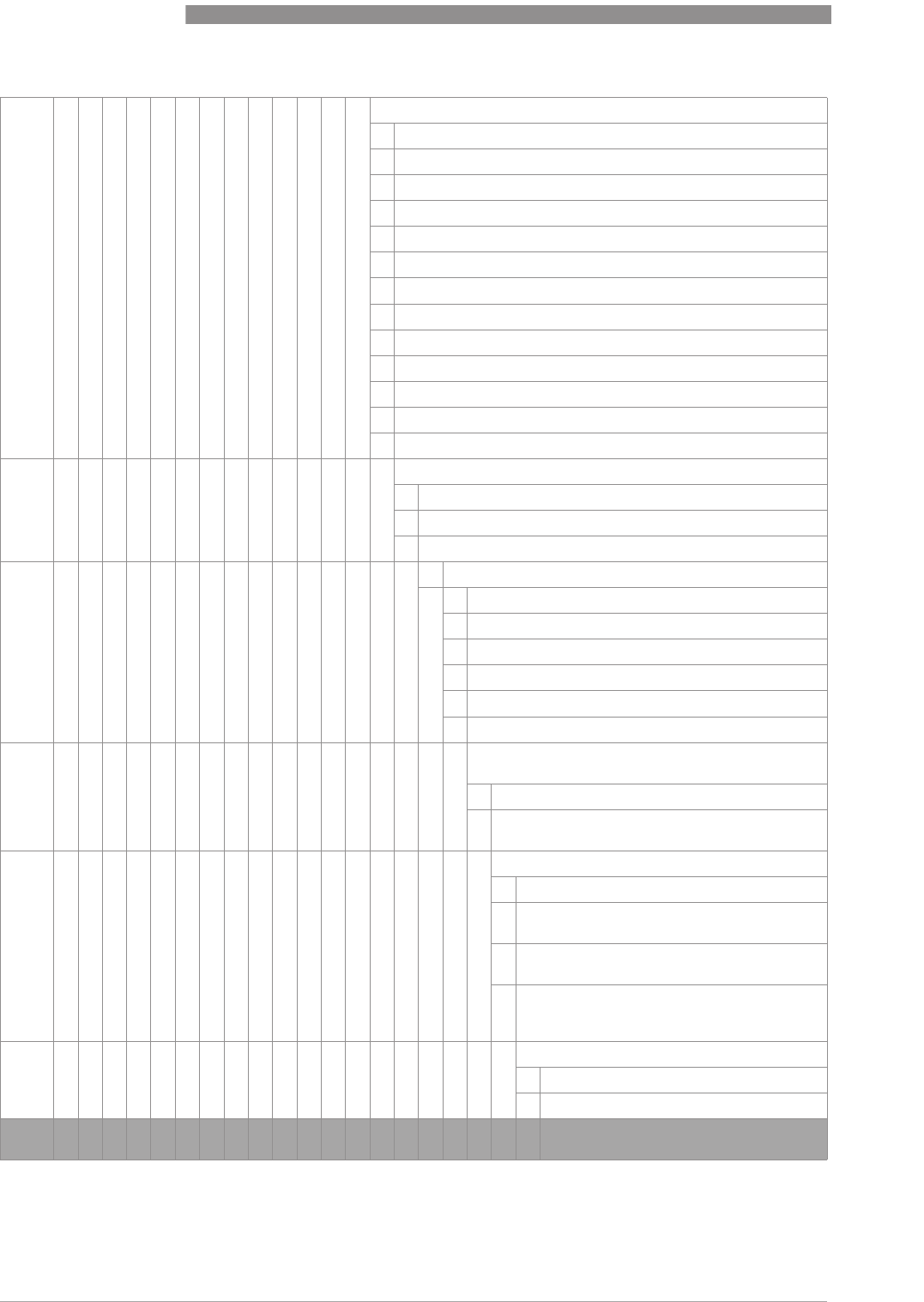
10
APPENDIX
128
OPTIWAVE 7400-24 C
www.krohne.com 12/2015 - 4003518001 - MA OPTIWAVE7400-24-R01-en
Display language (English is included in all language packs)
Display language (English is included in all language packs)Display language (English is included in all language packs)
Display language (English is included in all language packs)
0Without
1English
2German
3French
4Italian
5Spanish
6Portuguese
7Japanese
8Chinese (simplified)
ARussian
BPolish
CTurkish
DCzech
Version
VersionVersion
Version
0KROHNE (RAL 9006 / RAL 5005)
6KROHNE USA (FCC)
AKMIC L (for liquid applications)
0Options for remote version (OPTIWAVE 7400 F)
Options for remote version (OPTIWAVE 7400 F)Options for remote version (OPTIWAVE 7400 F)
Options for remote version (OPTIWAVE 7400 F)
0Without
6Signal cable 10m / Grey (std) or Blue (Ex)
7Signal cable 25m / Grey (std) or Blue (Ex)
8Signal cable 50m / Grey (std) or Blue (Ex)
ASignal cable 75m / Grey (std) or Blue (Ex)
BSignal cable 100m / Grey (std) or Blue (Ex)
Adaptor for OPTIWAVE 7300 C process
Adaptor for OPTIWAVE 7300 C process Adaptor for OPTIWAVE 7300 C process
Adaptor for OPTIWAVE 7300 C process
connections
connectionsconnections
connections
0Without
1Adaptor for OPTIWAVE 7300 C flange system
(before 2009)
Calibration certificate
Calibration certificateCalibration certificate
Calibration certificate
0Without
1Calibration certificate ±2mm (0.2¨) up to
10 m (32.81 ft) 2 points
2Calibration certificate ±2mm (0.2¨) up to
10 m (32.81 ft) 5 points
3Calibration certificate ±2mm (0.2¨) up to
10 m (32.81 ft) 5 points specified by the
customer min. ≥400 mm (12¨)
Tag N
Tag NTag N
Tag N°
0Without
3Tag n° on st. steel plate
1 0 Order code (complete this code on the
Order code (complete this code on the Order code (complete this code on the
Order code (complete this code on the
pages that follow)
pages that follow)pages that follow)
pages that follow)

APPENDIX
10
129
OPTIWAVE 7400-24 C
www.krohne.com12/2015 - 4003518001 - MA OPTIWAVE7400-24-R01-en
Other constructions
Other constructionsOther constructions
Other constructions
0Without
1NACE-Design (MR 0175 / MR 0103 /
ISO 15156)
3Heating / Cooling (Metallic Horn
only)
5Purging (Metallic Horn only)
6Purging + Heating / Cooling
(Metallic Horn only) 2
VF74
VF74VF74
VF74 4 1 0 Order code
Order codeOrder code
Order code
1DIP= Dust Ignition Proof
2Minimum flange diameter DN150 (6¨)

10
APPENDIX
130
OPTIWAVE 7400-24 C
www.krohne.com 12/2015 - 4003518001 - MA OPTIWAVE7400-24-R01-en
10.2 Spare parts
We supply spare parts for this device. When you send an order for a mechanical spare part, use
the reference numbers in the table that follows. When you send an order for an electronic spare
part, refer to
Order code
on page 122 and use the VF74 order code.
Mechanical spare parts
XF74 4 0 0 0 OPTIFLEX 7400 C 24 GHz Non-contact Radar (FMCW) level meter for liquids
OPTIFLEX 7400 C 24 GHz Non-contact Radar (FMCW) level meter for liquidsOPTIFLEX 7400 C 24 GHz Non-contact Radar (FMCW) level meter for liquids
OPTIFLEX 7400 C 24 GHz Non-contact Radar (FMCW) level meter for liquids
Pressure / Temperature / Sealing
Pressure / Temperature / SealingPressure / Temperature / Sealing
Pressure / Temperature / Sealing
0Without
1 40 bar / -40°C...+150°C (-40°F…+302°F) / FKM, FPM
- for the Metallic Horn antenna and Wave Guide
540 bar / -50°C...+130°C (-58°F…+266°F) / EPDM
- for the Metallic Horn antenna and Wave Guide
640 bar / -20°C...+150°C (-4°F…+302°F) / Kalrez 6375
- for the Metallic Horn antenna and Wave Guide
A40 bar / -60°C...+130°C (-76°F…+266°F) / PFA - for the Metallic Horn antenna and Wave Guide
D40 bar / -40°C...+200°C (-40°F…+392°F) / FKM (Viton)
- for the Metallic Horn antenna and Wave Guide
K40 bar / -20°C...+250°C (-4°F…+482°F) / Kalrez 6375
- for the Metallic Horn antenna and Wave Guide
R16 bar / -20°C...+100°C (-4°F…+212°F) / PP - for the PP Wave Horn antenna
T40 bar / -50°C...+150°C (-58°F…+302°F) / PTFE - for the PTFE Wave Horn antenna
Material and Antenna
Material and AntennaMaterial and Antenna
Material and Antenna
0Without
1316L / Metallic horn (sheet metal) DN80 (3¨)
2316L / Metallic horn (sheet metal) DN100 (4¨)
3316L / Metallic horn (sheet metal) DN150 (6¨)
4316L / Metallic horn (sheet metal) DN200 (8¨)
GPP / Wave Horn, maximum socket length 200 mm / 7.9¨
HPTFE / Wave Horn, maximum nozzle length 200 mm / 7.9¨
L316L /Metallic wave guide ≤1m (3.28ft)
M316L /Metallic wave guide ≤1.5m (4.92ft)
N316L / Metallic wave guide ≤2m (6.56ft)
P316L / Metallic wave guide ≤2.5 m (8.2 ft)
R316L / Metallic wave guide ≤3m (9.84ft)
S316L / Metallic wave guide ≤3.5 m (11.48 ft)
T316L / Metallic wave guide ≤4 m (13.12 ft)
U316L / Metallic wave guide ≤4.5 m (14.76 ft)
V316L / Metallic wave guide ≤5m (16.4ft)
W316L / Metallic wave guide ≤5.5 m (18.04 ft)
X316L / Metallic wave guide ≤6 m (19.68 ft)
XF74
XF74XF74
XF74 4 0 0 0 Order code (complete this code on the pages that follow)
Order code (complete this code on the pages that follow)Order code (complete this code on the pages that follow)
Order code (complete this code on the pages that follow)

APPENDIX
10
131
OPTIWAVE 7400-24 C
www.krohne.com12/2015 - 4003518001 - MA OPTIWAVE7400-24-R01-en
Material and Antenna extension
Material and Antenna extensionMaterial and Antenna extension
Material and Antenna extension
0Without
6PTFE, antenna extension for maximum nozzle length 300 mm / 11.8¨ 1
7PTFE, antenna extension for maximum nozzle length 400 mm / 15.7¨ 1
8PTFE, antenna extension for maximum nozzle length 500 mm / 19.7¨ 1
E316L / 100 mm (4¨) for the Metallic Horn antenna option only 1
F316L / 200 mm (8¨) for the Metallic Horn antenna option only 1
G316L / 300 mm (12¨) for the Metallic Horn antenna option only 1
H316L / 400 mm (16¨) for the Metallic Horn antenna option only 1
K316L / 500 mm (20¨) for the Metallic Horn antenna option only 1
R316L / 1000 mm (40¨) for the Metallic Horn antenna option only 1
W316L / "S" extension 1
X316L / "L" (right angle) extension 1
Y316L / Distance piece for high-temperature (HT) version
(Metallic Horn or Wave Guide antennas)
Process connection: Size / Pressure rating / Flange finish
Process connection: Size / Pressure rating / Flange finishProcess connection: Size / Pressure rating / Flange finish
Process connection: Size / Pressure rating / Flange finish
000Without
Threaded - ISO 228
G P 0 G1½ 2
Threaded - ASME B1.20.1
G A 0 1½NPT 2
EN / DIN Flanges - EN 1092-1 3
H E 1 DN50 PN16 - Type B1 flange 4
H G 1 DN50 PN40 - Type B1 flang 4
L E 1 DN80 PN16 - Type B1 flange
L G 1 DN80 PN40 - Type B1 flange
M E 1 DN100 PN16 - Type B1 flange
M G 1 DN100 PN40 - Type B1 flange
P E 1 DN150 PN16 - Type B1 flange
P G 1 DN150 PN40 - Type B1 flange
R E 1 DN200 PN16 - Type B1 flange 5
R G 1 DN200 PN40 - Type B1 flange 5
ASME B16.5 / ANSI Flanges 3
H 1 A 2¨ 150 lb RF 4
H 2 A 2¨ 300 lb RF 4
L 1 A 3¨ 150 lb RF
L 2 A 3¨ 300 lb RF
M 1 A 4¨ 150 lb RF
M 2 A 4¨ 300 lb RF
P 1 A 6¨ 150 lb RF
P 2 A 6¨ 300 lb RF
R 1 A 8¨ 150 lb RF 5
R 2 A 8¨ 300 lb RF 5
XF74
XF74XF74
XF74 4 0 0 0 Order code (complete this code on the pages that follow)
Order code (complete this code on the pages that follow)Order code (complete this code on the pages that follow)
Order code (complete this code on the pages that follow)
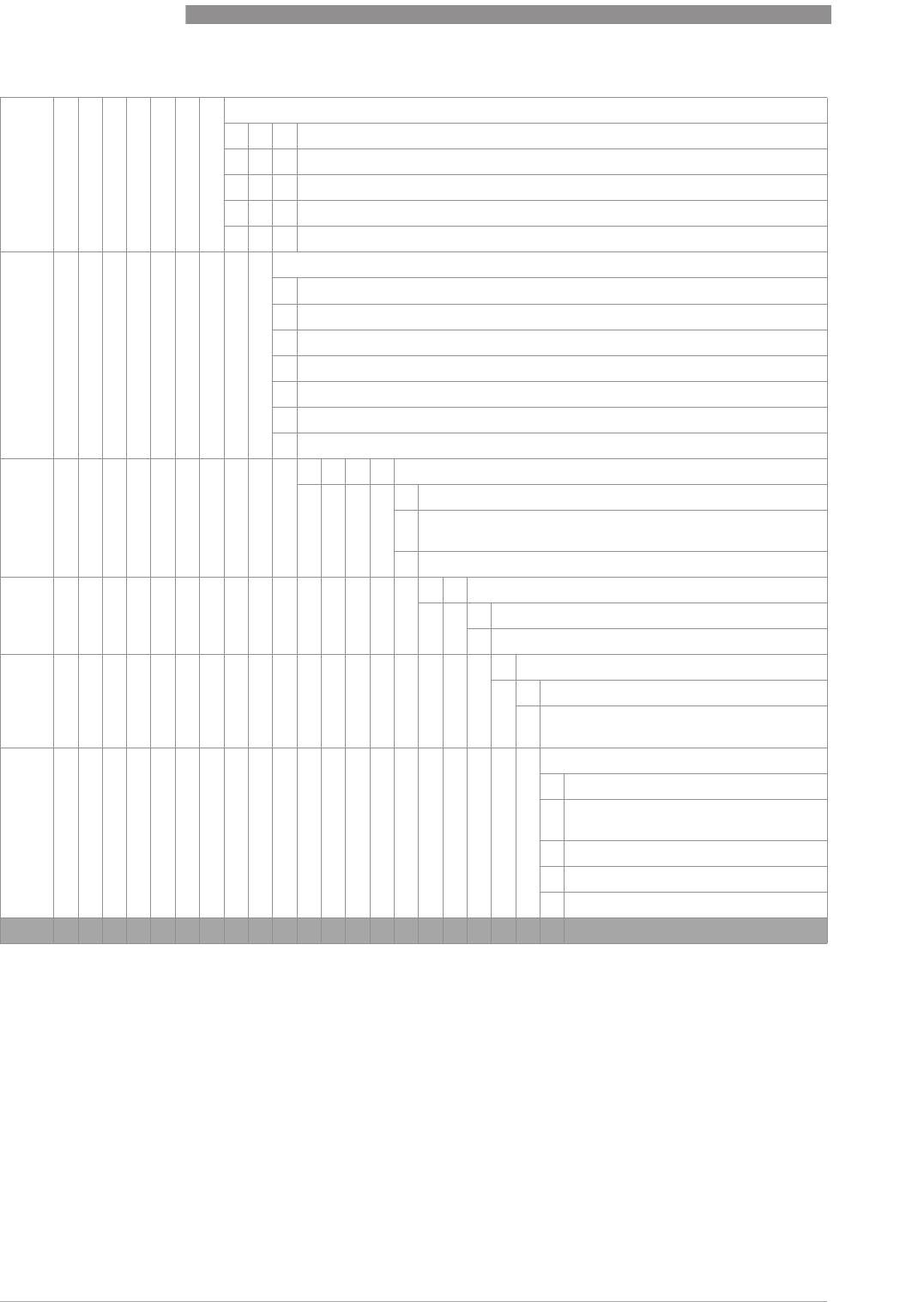
10
APPENDIX
132
OPTIWAVE 7400-24 C
www.krohne.com 12/2015 - 4003518001 - MA OPTIWAVE7400-24-R01-en
JIS B2220 Flanges
H U P 10K 50A RF 4
L U P 10K 80A RF
M U P 10K 100A RF
PUP10K 150A RF
R U P 10K 200A RF 5
Alternative flange faces
0Without
2Type B2, EN 1092-1 (surface roughness must be specified in the order)
3Type C, EN 1092-1 (Tongue)
4Type D, EN 1092-1 (Groove)
5Type E, EN 1092-1 (Spigot)
6Type F, EN 1092-1 (Recess)
BFF, ASME B16.5 (Flat face)
0 0 0 0 Version
VersionVersion
Version
0Standard orders and orders for solid applications in China
6Orders with FCC radio approval (FCC Part 15 and RSS-
210)
AOrders for liquid applications in China
0 0 Adaptor
AdaptorAdaptor
Adaptor
0Without
1Adaptor for BM 70x flange system
0TAG Number
TAG NumberTAG Number
TAG Number
0Without
1Tag No. stainless steel plate
(16 characters max.)
Extra option
Extra optionExtra option
Extra option
0Without
1NACE design
(MR0175 / MR0103 / ISO 15156)
3Heating / Cooling 6
5Purge 6
6Purge + Heating / Cooling 6
XF74
XF74XF74
XF74 4 0 0 0 0 0 0 0 Order code
Order codeOrder code
Order code
1For device dimensions, refer to the "Dimensions and weights" section
2For the PP Wave Horn antenna option only
3Other flange faces are available. Refer to your local supplier for more data. Flanges with the PTFE Wave Horn antenna option have a
slip on-type design with an anti-blowout feature.
4Minimum flange size for the PTFE Wave Horn antenna. This is not available for the Metallic Horn antenna.
5This flange is not available for the PTFE Wave Horn antenna option
6For DN150 and DN200 Metallic Horn antenna only
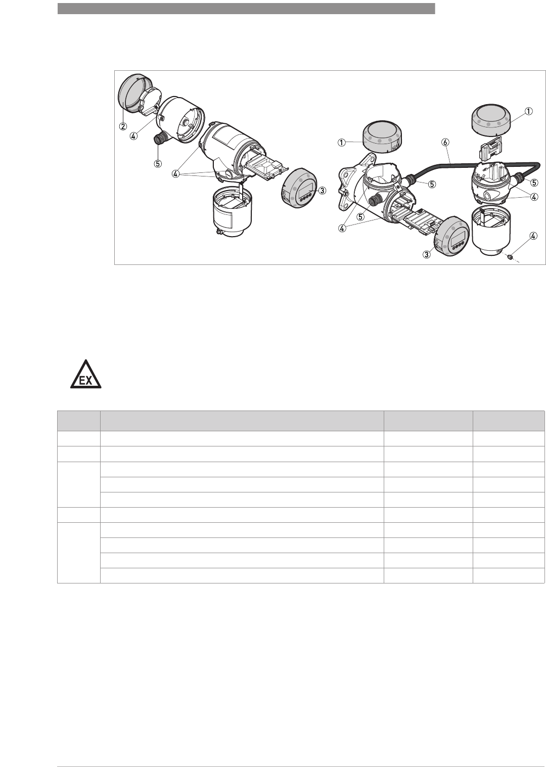
APPENDIX
10
133
OPTIWAVE 7400-24 C
www.krohne.com12/2015 - 4003518001 - MA OPTIWAVE7400-24-R01-en
Other spare parts
Figure 10-1: Other spare parts
1 Cover without LCD display
2 Cover for Ex d module
3 Cover with LCD display
4 Set of fasteners for housing (lock screw, gaskets)
5 Cable gland
6 Signal cable (Non-Ex: grey, Ex: blue)
DANGER!
Remote version: Make sure that replacement signal cables for Ex-approved devices are supplied
by the manufacturer. Use of this signal cable is mandatory.
Item Description Quantity Part reference
1Cover without LCD display 1XF50010100
2Cover for Ex d module 1 1XF50010200
3Cover with LCD display (English / German / French / Italian) 1XF50010300
Cover with LCD display (English / Spanish / French / Portuguese) 1XF50010400
Cover with LCD display (English / Russian / Chinese / Japanese) 1XF50010500
4Set of fasteners for housing (lock screw, gaskets) 1 screw, 10 gaskets XF50010900
5Cable gland / M20×1.5; Plastic; Black; Non-Ex 1XF50030100
Cable gland / M20×1.5; Plastic; Blue; Ex i 1XF50030200
Cable gland / M20×1.5; Brass; Ex d 1XF50030300
Cable gland / M20×1.5; Stainless Steel 1XF50030400
10
APPENDIX
134
OPTIWAVE 7400-24 C
www.krohne.com 12/2015 - 4003518001 - MA OPTIWAVE7400-24-R01-en
10.3 Accessories
We supply accessories for this device. When you send an order for a accessories, please give the
reference numbers that follow:
6Signal cable 10 m / 32.8 ft (non-Ex: grey) 2 1XF50040100
Signal cable 25 m / 82 ft (non-Ex: grey) 2 1XF50040200
Signal cable 50 m / 164 ft (non-Ex: grey) 2 1XF50040300
Signal cable 75 m / 246 ft (non-Ex: grey) 2 1XF50040400
Signal cable 100 m / 328 ft (non-Ex: grey) 2 1XF50040500
Signal cable 10 m / 32.8 ft (Ex: blue) 3 1XF50040600
Signal cable 25 m / 82 ft (Ex: blue) 3 1XF50040700
Signal cable 50 m / 164 ft (Ex: blue) 3 1XF50040800
Signal cable 75 m / 246 ft (Ex: blue) 3 1XF50040900
Signal cable 100 m / 328 ft (Ex: blue) 3 1XF50041000
1Ex d-approved devices only
2For the remote version
3For the remote version. Make sure that replacement signal cables for Ex-approved devices are supplied by the manufacturer. Use of
this signal cable is mandatory.
Item Description Quantity Part reference
Figure 10-2: Accessories
1 HMI service tool
2 Viator RS232 / HART converter
3 Viator USB / HART converter
Item Description Quantity Part reference
1HMI Service tool (English / German / French / Italian) 1 1XF74010600
HMI Service tool (English / Spanish / French / Portuguese) 1 1XF74010700
HMI Service tool (English / Russian / Chinese / Japanese) 1 1XF74010800
HMI Service tool (English / Czech / Polish / Turkish) 1 1XF74xxxxxx
2Viator RS232 / HART converter 1XF74020600
3Viator USB / HART converter 1XF74020700
4EMI/RFI shielding gasket 1XF74050600
1If the device does not have the LCD display option, use this accessory to change the device configuration

APPENDIX
10
135
OPTIWAVE 7400-24 C
www.krohne.com12/2015 - 4003518001 - MA OPTIWAVE7400-24-R01-en
10.4 Glossary
D
E
F
H
I
L
Dead zone
Dead zoneDead zone
Dead zone Non-measurement zone.
Dielectric constant
Dielectric constantDielectric constant
Dielectric constant An electrical property of the product to be measured used in Radar
measurement. Also known as εr, DK and relative permittivity. Defines the
strength of the wave reflected back to the device's signal converter.
Distance
DistanceDistance
Distance The distance from the face of flange to the level (1 product) or the surface
of the top product (2 or more products). See the diagrams at the end of this
section.
Drop antenna
Drop antennaDrop antenna
Drop antenna A new generation of antenna made of PP or PTFE. It has an ellipsoidal
shape for a more precise emission of radar signals.
DTM
DTMDTM
DTM Device Type Manager. A driver for use in the PACTware™ program. All data
and functions of the device are included in it.
Electromagnetic compatibility
Electromagnetic compatibilityElectromagnetic compatibility
Electromagnetic compatibility Defines how much a device influences or is influenced by other devices that
generate electromagnetic fields during operation. Refer to European
standard EN 61326-1 for further details.
FMCW
FMCWFMCW
FMCW Frequency-modulated continuous-wave radar technology. The signal is
continuously present, but the frequency is modulated, usually in
successive linear ramps over time (frequency sweeps).
Hazardous area
Hazardous areaHazardous area
Hazardous area An area with a potentially explosive atmosphere. Trained personnel can
install and use a device in this area. The device must be ordered with the
appropriate options. The device requires approvals (ATEX, IECEx, FM, CSA,
NEPSI etc.) related to site specifications. You can find more data about
hazardous areas in the Ex Manuals and Ex Certificates of Compliance.
Horn (cone) antenna
Horn (cone) antennaHorn (cone) antenna
Horn (cone) antenna A common antenna for most applications. It is used for the controlled
emission and collection of radar signals.
Hygienic antenna
Hygienic antennaHygienic antenna
Hygienic antenna An antenna made of a material that agrees with FDA regulations. It can be
supplied with common hygienic process connection options (Tri-Clamp
®
,
BioControl
®
, SMS, ...).
Interference signals
Interference signalsInterference signals
Interference signals False radar reflections.
Level
LevelLevel
Level Height from the bottom of the tank (user-defined) to the surface of the top
product (Tank height – distance). See the diagrams at the end of this
section.

10
APPENDIX
136
OPTIWAVE 7400-24 C
www.krohne.com 12/2015 - 4003518001 - MA OPTIWAVE7400-24-R01-en
M
O
P
R
S
U
V
Mass
MassMass
Mass Total mass of tank contents.
Operators
OperatorsOperators
Operators Users who can choose how to display measurements. They cannot
configure the device in supervisor mode.
PACTware
PACTwarePACTware
PACTware™Software that operates and configures field devices from a remote
workstation. It is not necessary to use fieldbus software or programs
developed by the manufacturer.
Radar reflection
Radar reflectionRadar reflection
Radar reflection Signal reflected from the surface of the tank contents.
Signal converter
Signal converterSignal converter
Signal converter A set of electronic components in the device that send the measurement
signal through some signal filters.
Supervisor
SupervisorSupervisor
Supervisor Users who can configure the device in supervisor mode. They cannot
configure the device in service mode.
Ullage volume
Ullage volumeUllage volume
Ullage volume Unfilled volume. See the diagrams at the end of this section.
Volume
VolumeVolume
Volume Total volume of tank contents.
APPENDIX
10
137
OPTIWAVE 7400-24 C
www.krohne.com12/2015 - 4003518001 - MA OPTIWAVE7400-24-R01-en
Figure 10-3: Measurement definitions: distance
1 Distance
2 Dead zone
3 Flange facing
4 Gas (Air)
5 Tank height
6 Ullage volume or mass
Figure 10-4: Measurement definitions: level
1 Level
2 Volume or mass

11
NOTES
138
OPTIWAVE 7400-24 C
www.krohne.com 12/2015 - 4003518001 - MA OPTIWAVE7400-24-R01-en

NOTES
11
139
OPTIWAVE 7400-24 C
www.krohne.com12/2015 - 4003518001 - MA OPTIWAVE7400-24-R01-en

KROHNE – Process instrumentation and measurement solutions
•
Flow
•
Level
•
Temperature
•
Pressure
•
Process Analysis
•
Services
Head Office KROHNE Messtechnik GmbH
Ludwig-Krohne-Str. 5
47058 Duisburg (Germany)
Tel.: +49 203 301 0
Fax: +49 203 301 10389
info@krohne.com
© KROHNE 12/2015 - 4003518001 - MA OPTIWAVE7400-24-R01-en - Subject to change without notice.
The current list of all KROHNE contacts and addresses can be found at:
www.krohne.com