Kenwood USA 442000 Push to talk radio. User Manual
Kenwood USA Corporation Push to talk radio.
Contents
- 1. Users Manual
- 2. User Manual
Users Manual
B5A-****-00 (K)
USER GUIDE
NX-5200
NX-5300
NX-5400

VHF DIGITAL TRANSCEIVER/
UHF DIGITAL TRANSCEIVER
700/800MHz DIGITAL TRANSCEIVER
NX-5200/ NX-5300
NX-5400
USER GUIDE
ENGLISH
Firmware Copyrights
The title to and ownership of copyrights for fi rmware
embedded in KENWOOD product memories are
reserved for JVC KENWOOD Corporation.
NXDN™
NXDN™ is a protocol name for a new digital communications
system using 4-level FSK technology which has been co-
developed by JVC KENWOOD and Icom.
This device made under license under one or more of the
following US Patents: 5,502,767.
The AMBE+2TM voice coding Technology embodied in this
product is protected by intellectual property rights including
patent rights, copyrights and trade secrets of Digital Voice
Systems, Inc. This voice coding Technology is licensed solely
for use within this Communications Equipment. The user
of this Technology is explicitly prohibited from attempting to
extract, remove, decompile, reverse engineer, or disassemble
the Object Code, or in any other way convert the Object Code
into a human-readable form. U.S. Patent Nos. #5,826,222,
#5,754,974, #5,701,390, #5,715,365, #5,649,050, #5,630,011
and #5,581,656

Terminal Descriptions
Universal connector
It is possible to use a resin-based cover for the Universal connector.
No. Name Description Specifi cation I/O
1 SSW Ext/Int Speaker Switch Input Hi: INT, Low: EXT I
2 SP+ BTL Output + for External Speaker Standard load 8 O
3 SP- BTL Output – for External Speaker Standard load 8 O
4 MSW Ext/Int MIC Switch Input Hi: INT, Low: EXT I
5 EMC External MIC Input Impedance: 1.8 kI
6 ME External MIC GND – –
7 PTT External PTT Input Low: PTT ON I
8 PF Programable Function Key Input Input voltage: 0 V - 3.3 V I
9 OPT Aux I/O Port (for EXT Option) I: 0 V - 3.3 V
O: Standard load 25 kI/O
10 E GND GND −
11 5V 5V 5V power supply output
Max output current: 140 mA O
12 TXD Serial Data Output Baud rate: 115200 bps max O
13 RXD Serial Data Input Baud rate: 115200 bps max I
14 EMC External MIC input Impedance: 1.8 kI
Antenna Terminal
50 impedance

i
THANK YOU
We are grateful you have chosen KENWOOD for your land
mobile radio applications.
This Users Guide covers only the basic operations of your portable
radio. Ask your dealer for information on any customized features
they may have added to your radio. For using details instruction
manual, refer to the following URL.
http://manual2.jvckenwood.com/en_contents/search/
NOTICES TO THE USER
◆ Government law prohibits the operation of unlicensed radio
transmitters within the territories under government control.
◆ Illegal operation is punishable by fi ne and/or imprisonment.
◆ Refer service to qualifi ed technicians only.
SAFETY: It is important that the operator is aware of and
understands hazards common to the operation of any transceiver.

ii
One or more of the following statements may be applicable:
FCC WARNING
This equipment generates or uses radio frequency energy.
Changes or modifi cations to this equipment may cause harmful
interference unless the modifi cations are expressly approved in the
instruction manual. The user could lose the authority to operate this
equipment if an unauthorized change or modifi cation is made.
INFORMATION TO THE DIGITAL DEVICE USER REQUIRED BY
THE FCC
This equipment has been tested and found to comply with the limits
for a Class B digital device, pursuant to Part 15 of the FCC Rules.
These limits are designed to provide reasonable protection against
harmful interference in a residential installation.
This equipment generates, uses and can generate radio
frequency energy and, if not installed and used in accordance
with the instructions, may cause harmful interference to radio
communications. However, there is no guarantee that the
interference will not occur in a particular installation. If this equipment
does cause harmful interference to radio or television reception,
which can be determined by turning the equipment off and on, the
user is encouraged to try to correct the interference by one or more of
the following measures:
• Reorient or relocate the receiving antenna.
• Increase the separation between the equipment and receiver.
• Connect the equipment to an outlet on a circuit different from
that to which the receiver is connected.
• Consult the dealer for technical assistance.
The RBRC Recycle seal found on KENWOOD
nickel metal hydride (Ni-MH) battery packs
indicates KENWOOD’s voluntary participation in
an industry program to collect and recycle Ni-MH
batteries after their operating life has expired. The
RBRC program is an alternative to disposing Ni-MH
batteries with your regular refuse or in municipal
waste streams, which is illegal in some areas.
For information on Ni-MH battery recycling in your area, call (toll
free) 1-800-8-BATTERY (1-800-822-8837).
KENWOOD’s involvement in this program is part of our commitment
to preserve our environment and conserve our natural resources.

iii
The RBRC Recycle seal found on KENWOOD
lithium-ion (Li-ion) battery packs indicates
KENWOOD’s voluntary participation in an industry
program to collect and recycle Li-ion batteries
after their operating life has expired. The RBRC
program is an alternative to disposing Li-ion
batteries with your regular refuse or in municipal
waste streams, which is illegal in some areas.
For information on Li-ion battery recycling in your area, call (toll
free) 1-800-8-BATTERY (1-800-822-8837).
KENWOOD’s involvement in this program is part of our commitment
to preserve our environment and conserve our natural resources.
PRECAUTIONS
• Do not charge the transceiver and battery pack when they are wet.
• Ensure that there are no metallic items located between the
transceiver and the battery pack.
• Do not use options not specifi ed by KENWOOD.
• If the die-cast chassis or other transceiver part is damaged, do not
touch the damaged parts.
• If a headset or headphone is connected to the transceiver, reduce
the transceiver volume. Pay attention to the volume level when
turning the squelch off.
• Do not place the microphone cable around your neck while near
machinery that may catch the cable.
• Do not place the transceiver on unstable surfaces.
• Ensure that the end of the antenna does not touch your eyes.
• When the transceiver is used for transmission for many hours, the
radiator and chassis will become hot. Do not touch these locations
when replacing the battery pack.
• Do not immerse the transceiver in water.
• When water gets into the microphone opening or the speaker
grill, the voice level may become incoherent or distorted. Lightly
shake the transceiver to remove the water from the speaker and/or
microphone before operating the transceiver.
• Always switch the transceiver power off before installing optional
accessories.
iv
Turn the transceiver power off in the following locations:
• Near explosives or blasting sites.
• In aircrafts. (Any use of the transceiver must follow the
instructions and regulations provided by the airline crew.)
• Where restrictions or warnings are posted regarding the use of
radio devices, including but not limited to medical facilities.
• Near persons wearing pacemakers.
Turn the transceiver power off in the following locations,
unless the model is specifi cally qualifi ed for such use
(Intrinsically Safe such as approved by Factory Mutual, CSA):
• In explosive atmospheres (infl ammable gas, dust particles,
metallic powders, grain powders, etc.).
• While taking on fuel or while parked at gasoline service stations.
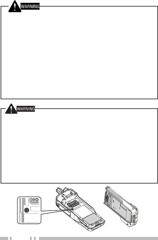
• Do not remove the black sheet from the reverse side of the
transceiver (refer to the illustration below). Removal of this
sheet decreases the waterproof effi ciency of the transceiver and
may cause malfunctions if water seeps into the transceiver.
• The orange seal on the reverse side of the transceiver is
important with respect to the waterproof effi ciency of the
transceiver. Do not place stickers or other materials on or
around the seal shown in the fi gure, or on the reverse side of
the battery pack. Doing so will impair the waterproof effi ciency
of the transceiver and may cause it to break down. Additionally,
in order to prevent damage to the seal, do not allow it to come
in contact with foreign materials.

v
• Do not disassemble or modify the transceiver for any reason.
• Do not place the transceiver on or near airbag equipment while
the vehicle is running. When the airbag infl ates, the transceiver
may be ejected and strike the driver or passengers.
• Do not transmit while touching the antenna terminal or if
any metallic parts are exposed from the antenna covering.
Transmitting at such a time may result in a high-frequency burn.
• If an abnormal odor or smoke is detected coming from the
transceiver, switch the transceiver power off immediately,
remove the battery pack from the transceiver, and contact your
KENWOOD dealer.
• Use of the transceiver while you are driving may be against
traffi c laws. Please check and observe the vehicle regulations
in your area.
• Do not expose the transceiver to extremely hot or cold
conditions.
• Do not carry the battery pack (or battery case) with metal
objects, as they may short the battery terminals.
• Danger of explosion if the battery is incorrectly replaced;
replace only with the same type.
• When attaching a commercial strap to the transceiver,
ensure that the strap is durable. In addition, do not swing the
transceiver around by the strap; you may inadvertently strike
and injure another person with the transceiver.
• If a commercially available neck strap is used, take care not to
let the strap get caught on nearby machine.
• When operating the transceiver in areas where the air is dry, it
is easy to build up an electric charge (static electricity).
When using an earphone accessory in such conditions, it is
possible for the transceiver to send an electric shock through
the earphone and to your ear. We recommend you use only
a speaker/microphone in these conditions, to avoid electric
shocks.

vi
Information concerning the battery pack:
The battery pack includes fl ammable objects such as organic solvent.
Mishandling may cause the battery to rupture producing fl ames or
extreme heat, deteriorate, or cause other forms of damage to the
battery. Please observe the following prohibitive matters.
• Do not disassemble or reconstruct battery!
The battery pack has a safety function and protection circuit to
avoid danger. If they suffer serious damage, the battery may
generate heat or smoke, rupture, or burst into fl ame.
• Do not short-circuit the battery!
Do not join the + and – terminals using any form of metal (such
as a paper clip or wire). Do not carry or store the battery pack
in containers holding metal objects (such as wires, chain-
necklace or hairpins). If the battery pack is short-circuited,
excessive current will fl ow and the battery may generate heat
or smoke, rupture, or burst into fl ame. It will also cause metal
objects to heat up.
• Do not incinerate or apply heat to the battery!
If the insulator is melted, the gas release vent or safety function
is damaged, or the electrolyte is ignited, the battery may
generate heat or smoke, rupture, or burst into fl ame.
• Do not leave the battery near fi res, stoves, or other heat
generators (areas reaching over 80°C/ 176°F)!
If the polymer separator is melted due to high temperature,
an internal short-circuit may occur in the individual cells and
the battery may generate heat or smoke, rupture, or burst into
fl ame.
• Avoid immersing the battery in water or getting it wet by
other means!
If the battery becomes wet, wipe it off with a dry towel before
use. If the battery’s protection circuit is damaged, the battery
may charge at extreme current (or voltage) and an abnormal
chemical reaction may occur. The battery may generate heat or
smoke, rupture, or burst into fl ame.
DANGER

vii
• Do not charge the battery near fi res or under direct
sunlight!
If the battery’s protection circuit is damaged, the battery
may charge at extreme current (or voltage) and an abnormal
chemical reaction may occur. The battery may generate heat or
smoke, rupture, or burst into fl ame.
• Use only the specifi ed charger and observe charging
requirements!
If the battery is charged in unspecifi ed conditions (under high
temperature over the regulated value, excessive high voltage or
current over regulated value, or with a remodelled charger), it
may overcharge or an abnormal chemical reaction may occur.
The battery may generate heat or smoke, rupture, or burst into
fl ame.
• Do not pierce the battery with any object, strike it with an
instrument, or step on it!
This may break or deform the battery, causing a short-circuit.
The battery may generate heat or smoke, rupture, or burst into
fl ame.
• Do not jar or throw the battery!
An impact may cause the battery to leak, generate heat
or smoke, rupture, and/or burst into fl ame. If the battery’s
protection circuit is damaged, the battery may charge at an
abnormal current (or voltage), and an abnormal chemical
reaction may occur.
• Do not use the battery pack if it is damaged in any way!
The battery may generate heat or smoke, rupture, or burst into
fl ame.
• Do not solder directly onto the battery!
If the insulator is melted or the gas release vent or safety
function is damaged, the battery may generate heat or smoke,
rupture, or burst into fl ame.
• Do not reverse the battery polarity (and terminals)!
When charging a reversed battery, an abnormal chemical
reaction may occur. In some cases, an unexpected large
amount of current may fl ow upon discharging. The battery may
generate heat or smoke, rupture, or burst into fl ame.
DANGER

viii
NOTIFICATION OF WATER-RESISTANT MODEL
Water Resistance and Maintenance
Water-Resistant Model transceiver conforms to the following standards.
Immersion: The transceiver retains its water resistant capabilities
outlined in U.S. Military Standards when submersed in water at a depth
of 1 meter (3.28 feet) for 2 hours.
IP66/ IP67/ IP68: The IP standard is the protection level specifi ed
by the international standard IEC 60529. The fi rst numeral indicates
the "dust-resistant level" and the second numeral indicates the "water-
resistant" level.
Note:Initial water-resistant tests and procedures are performed
products upon being ordered from KENWOOD.
PRECAUTIONS
• The applicable standards listed above do not assure that the
transceiver can be used in water. The transceiver may be damaged
in a situation in which the maximum depth is over 1 meter or the
maximum submersion time exceeds 2 hours.
• Observe the following precautions to maintain the transceiver’s
water-resistant performance:
a) Do not drop or apply strong physical shocks to the transceiver.
b) Do not disassemble or attempt to modify the transceiver. (If it is
disassembled or modifi ed, its performance is not guaranteed.)
c) Do not soak the transceiver in water that contains a solvent or
surfactant, such as detergent or alcohol.
• If it is soaked in muddy water or salt water (including sea water),
it may become corroded. Immediately fl ush with fresh water and
then wipe dry with a soft cloth.
• If water is splashed onto the microphone, the battery, or the
antenna terminal, clean and dry them with a soft cloth before
reconnecting to the transceiver.
• When water gets into the microphone opening or the speaker
grill, the voice level may become low or distorted. Lightly shake
the transceiver to remove the water from the speaker and/or
microphone before operating the transceiver.

ix
• Use of any option on the transceiver not specifi ed by KENWOOD,
may reduce or void the water resistant and dust resistant
performance.
• Read the transceiver’s instruction manual for other precautions on
usage.
x
• Do not charge the battery for longer than the specifi ed
time!
If the battery pack has not fi nished charging even after the
regulated time has passed, stop it. The battery may generate
heat or smoke, rupture, or burst into fl ame.
• Do not place the battery pack into a microwave or high
pressure container!
The battery may generate heat or smoke, rupture, or burst into
fl ame.
• Keep ruptured and leaking battery packs away from fi re!
If the battery pack is leaking (or the battery emits a bad odor),
immediately remove it from fl ammable areas. Electrolyte
leaking from battery can easily catch on fi re and may cause the
battery to generate smoke or burst into fl ame.
• Do not use an abnormal battery!
If the battery pack emits a bad odor, appears to have color
changes, is deformed, or seems abnormal for any other reason,
remove it from the charger or operating equipment and do not
use it. The battery may generate heat or smoke, rupture, or
burst into fl ame.
• Do not reverse-charge or reverse-connect the battery!
The battery pack has positive and negative poles. If the battery
pack does not smoothly connect with a charger or operating
equipment, do not force it; check the polarity of the battery. If
the battery pack is reverse-connected to the charger, it will be
reverse-charged and an abnormal chemical reaction may occur.
The battery may generate heat or smoke, rupture, or burst into
fl ame.
• Do not touch a ruptured and leaking battery!
If the electrolyte liquid from the battery gets into your eyes,
wash your eyes out with fresh water as soon as possible,
without rubbing your eyes. Go to the hospital immediately. If
left untreated, it may cause eye-problems.
DANGER

1
UNPACKING AND CHECKING EQUIPMENT
Note:
◆The following unpacking instructions are for use by your
KENWOOD dealer, an authorized KENWOOD service facility, or
the factory.
Carefully unpack the transceiver. We recommend that you
identify the items listed in the following table before discarding
the packing material. If any items are missing or have
been damaged during shipment, fi le a claim with the carrier
immediately.
SUPPLIED ACCESSORIES
Belt clip . . . . . . . . . . . . . . . . . . . . . . . . . . . . . . . . . . . . . . . . . . . . . . . . 1
• Screws for belt clip (M3 x 8 mm) . . . . . . . . . . . . . . . . . . . . . . . . . . 2
Universal connector cap . . . . . . . . . . . . . . . . . . . . . . . . . . . . . . . . . . . 1
• Dressing screw . . . . . . . . . . . . . . . . . . . . . . . . . . . . . . . . . . . . . . . 1
• Packing (preassembled) . . . . . . . . . . . . . . . . . . . . . . . . . . . . . . . . 1
Users Guide . . . . . . . . . . . . . . . . . . . . . . . . . . . . . . . . . . . . . . . . . . . . 1
CONTENTS
UNPACKING AND CHECKING EQUIPMENT ............................ 1
SUPPLIED ACCESSORIES ............................................. 1
INSTALLING/ REMOVING THE (OPTIONAL) BATTERY PACK ..... 2
INSTALLING THE (OPTIONAL) ANTENNA ........................... 3
INSTALLING THE BELT CLIP .......................................... 3
INSTALLING THE CAP OVER THE UNIVERSAL CONNECTOR ..... 4
INSTALLING THE (OPTIONAL) SPEAKER/ MICROPHONE OR
HEADSET ................................................................ 4
GETTING ACQUAINTED .................................................. 5
DISPLAY ................................................................ 8
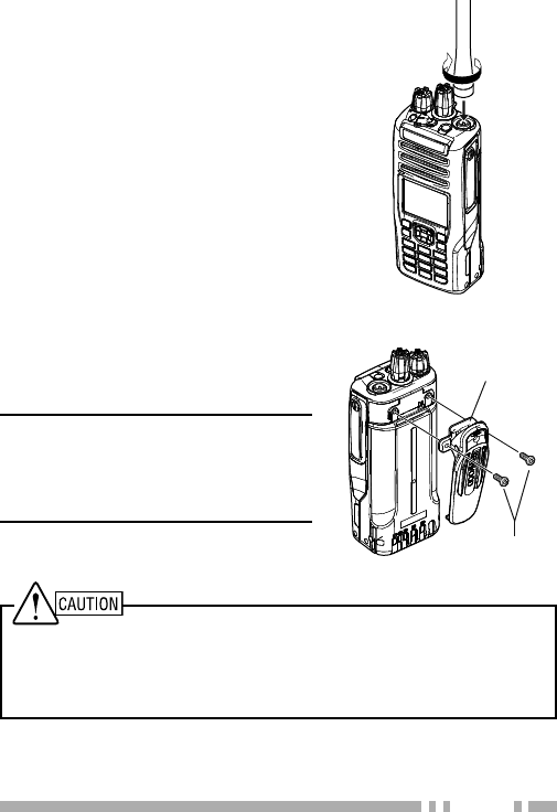
2
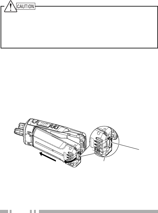
INSTALLING/ REMOVING THE (OPTIONAL)
BATTERY PACK
1 Match the guides of the battery pack with the corresponding
grooves on the upper rear of the transceiver, then fi rmly
press the battery pack to lock it in place.
2 Lock the safety catch to prevent accidentally pressing the
release latch and removing the battery pack.
3 To remove the battery pack, lift the safety catch, press the
release latch, then pull the battery pack away from the
transceiver.
Release latch
Safety catch
1
2
3
Installing/ Removing the Battery Pack
◆ Do not short the battery terminals or dispose of the battery by fi re.
◆ Never attempt to remove the casing from the battery pack.
◆ Install the battery pack after cleaning the battery pack contacts and
the transceiver terminals.
◆ Before charging a battery pack that is attached to the transceiver,
ensure that the safety catch is fi rmly closed.
3
INSTALLING THE (OPTIONAL) ANTENNA
Screw the antenna into the
connector on the top of the
transceiver by holding the antenna
at its base and turning it clockwise
until secure.
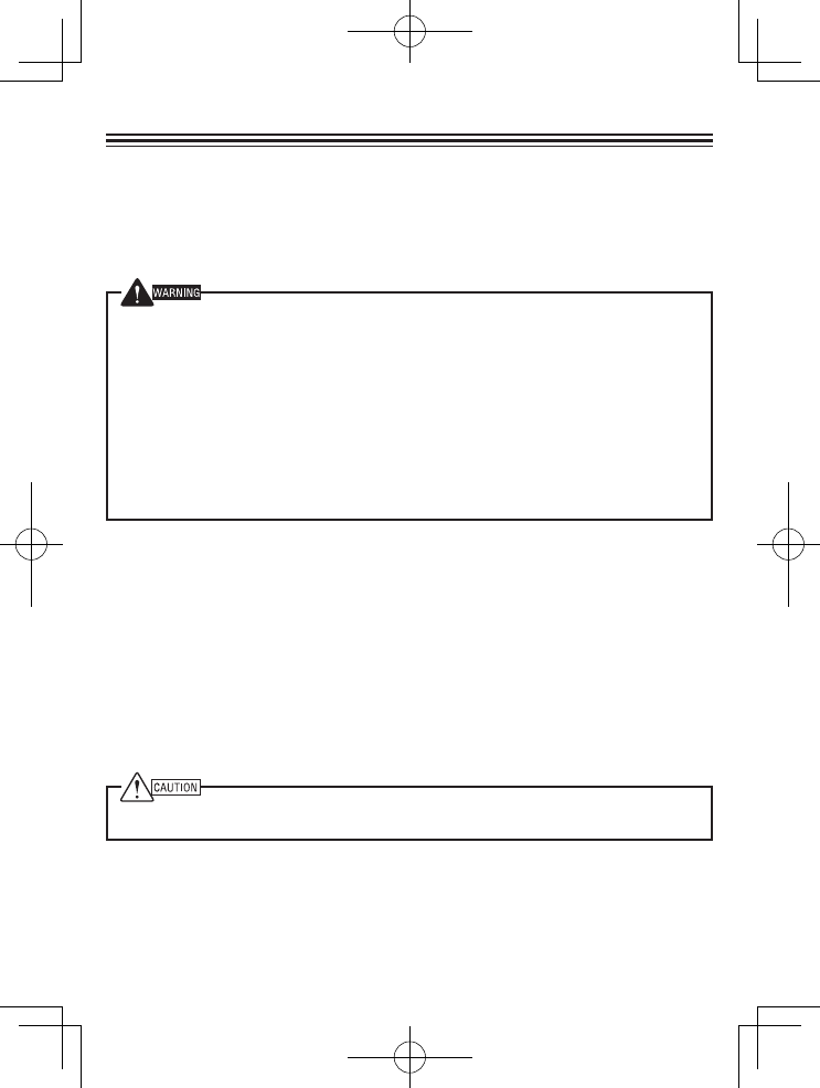
Do not use glue which is designed to prevent screw loosening when
installing the belt clip, as it may cause damage to the transceiver. Acrylic
ester, which is contained in these glues, may crack the transceiver’s
back panel.
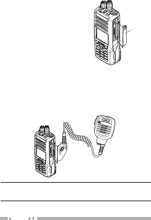
INSTALLING THE BELT CLIP
If necessary, attach the belt clip
using the two supplied M3 x 8 mm
binding screws.
Note:
◆If the belt clip is not installed, its
mounting location may get hot during
continuous transmission or when left
sitting in a hot environment.
Optional
antenna
M3 x 8 mm
Belt clip
screws
4
INSTALLING THE CAP OVER THE
UNIVERSAL CONNECTOR
1 If you are not using an optional
speaker/ microphone or
headset, install the cap over
the universal connector.
2 Secure the cap in place using
the dressing screw.
INSTALLING THE (OPTIONAL) SPEAKER/
MICROPHONE OR HEADSET
1 Insert the guide of the speaker/ microphone or headset
connector into the groove of the universal connector.
2 Secure the connector in place using the attached screw.
Note:
◆When not using an optional speaker/ microphone or headset,
install the cap over the universal connector.
Universal
connector cap
Optional
speaker/ microphone
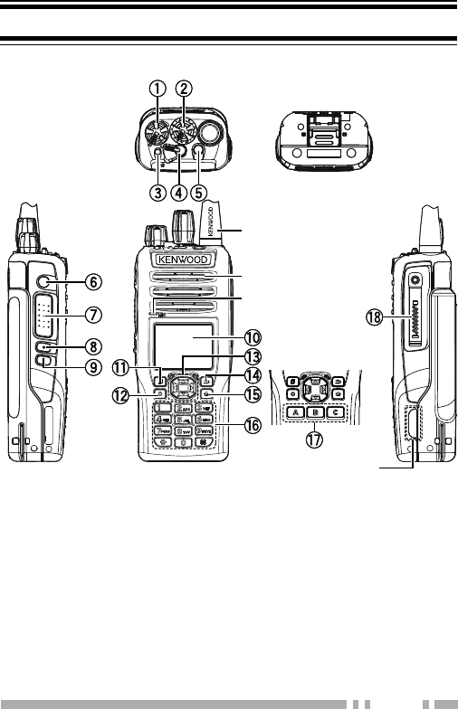
5
GETTING ACQUAINTED
a Power switch/ Volume control
Turn clockwise to switch the transceiver ON. Rotate to
adjust the volume. Turn counterclockwise fully to switch the
transceiver OFF.
b Selector knob
Rotate this control to activate its programmable function.
The default setting is Channel Select.
Antenna
Microphone
Speaker
Standard Key
model
KEYS AND CONTROLS
Micro SD
Card SLOT
Full Key model

6
c Transmit/ Receive/ Battery low indicator
Lights red while transmitting, green while receiving (on
Conventional channels only), and orange when receiving an
encoded call (i.e. 2-tone, DTMF signaling, etc.). Flashes red
when the battery power is low while transmitting. Replace
or recharge the battery pack when the battery power is low.
Note: This indicator can be disabled by your dealer.
d Lever switch
Switch the toggle position to activate its programmable
function. The O position turns the function ON. The ●
position turns the function OFF.
e Auxiliary (orange) key
Press to activate its programmable function.
f Side 1 key
Press to activate its programmable function.
g PTT (Push-To-Talk) switch
Press and hold this switch, then speak into the microphone
to call a station.
h Side 2 key
Press to activate its programmable function. Acts as an Up
key for certain transceiver settings.
i Side 3 key
Press to activate its programmable function. Acts as a
Down key for certain transceiver settings.
j LCD Display
Refer to the display on page 8.
k Menu key
Press to activate its programmable function. The default
key setting is [Menu].
l Function key
Press to activate its programmable function. The default
key setting is [Function].

7
m Left/ Right/ Up/ Down key
Press to activate its programmable function.
n Back key
Press to activate its programmable function. The default
key setting is [Back].
o Home key
Press to activate its programmable function. The default
key setting is [Home].
p Keypad (Full key model only)
Press the keys on the keypad to send DTMF tones. The
keypad keys can also be programmed with secondary
functions if a programmable function keys is programmed
as Function.
q A/ B/ C key (Standard key model only)
Press to activate its programmable function. The
programmed name appears on the bottom of the display.
r Universal connector
Connect the (optional) speaker/ microphone here.
Otherwise, keep the supplied cap in place.
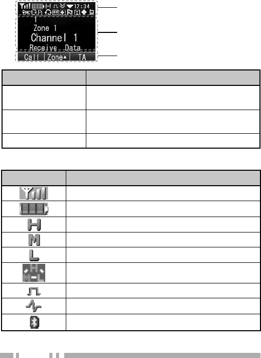
8
DISPLAY
Function Icon Area
Main Area
Key Guide Area
Display Area Description
Function Icon Area Display the various function Icons ,signal
strength indicator and battery power indicator.
Main Area Display the information of the transceiver
such as Channel number and Zone namber.
Key Guide Area Display the key functions (key guide).
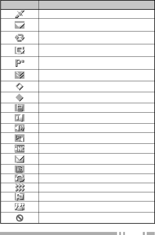
Basic Frame
Icon Description
Signal strength/ out of range indicator.
Battery power indicator.
The channel is using high transmit power.
The channel is using medium transmit power.
The channel is using low transmit power.
The channel is using auto transmit power.
Digital mode
Analog mode
Appears when the Bluetooth function is activated.
Function Icon
9
Icon Description
Appears when the GPS function is activated.
Appears when the current zone is added to the
scanning sequence. is activated.
Appears when you are using Scan mode.
Appears when the Priority scan is in progress.
Appears when the current channel is programmed
as a Priority channel.
Appears when the current CH/GIDl is added to the
scanning sequence.
Appears when the Scrambler/ Encryption (AES)
function is activated.
Appears when the Encryption (DES) function is
activated.
Appears when the Talk Around is activated.
Appears when the Monitor or Squelch Off function
is activated.
Appears when the External Speaker is activated.
Appears when the External Speaker (both) is
activated.
Appears when the Noise Cancel is activated.
Appears when there is a message stored in the
transceiver memory.
Appears when recognize the MicroSD / SD card.
Appears when the VOX is activated.
Appears when the Vibrator function is activated.
Appears when the Site Lock function is activated.
Appears when the Broadcast Call function is
activated.
Appears when the Survellance function is
activated.
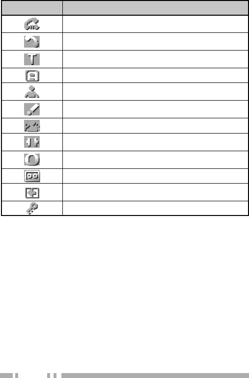
10
Icon Description
Appears when the Call Diversion function is
activated.
Selected group is programmed as telephone IDs or
RIC (Repeater Interconnect).
Appears when you have entered a Tactical Group
zone.
Appears when the AUX A is activated.
Appears when the Lone Worker function is
activated.
Appears when the Activity Detection function is
activated.
Appears when the OVCM function is activated.
Appears when the Compander function is
activated.
Appears when the Operator Selectable Tone
function is activated.
Appears when the Auto Recording is activated.
Appears when the Auto Reply Message is
activated.
Appears when the Key Lock function is activated.

© 2014 JVC KENWOOD Corporation
RADIO FREQUENCY ENERGY SAFETY INFORMATION
This KENWOOD transceiver has been tested and complies with the standards listed below, in regards
to Radio Frequency (RF) energy and electromagnetic energy (EME) generated by the transceiver.
• FCC RF exposure limits for
Occupational Use Only
. RF Exposure limits adopted by the FCC are generally
based on recommendations from the National Council on Radiation Protection and Measurements, & the
American National Standards Institute.
• FCC OET Bulletin 65 Edition 97-01 Supplement C
• American National Standards Institute (C95.1 – 1992)
• American National Standards Institute (C95.3 – 1992)
This KENWOOD transceiver generates RF EME while transmitting. RF EME (Radio Frequency Electric &
Magnetic Energy) has the potential to cause slight thermal, or heating effects to any part of your body less
than the recommended distance from this radio transmitter’s antenna. RF energy exposure is determined
primarily by the distance to and the power of the transmitting device. In general, RF exposure is minimized
when the lowest possible power is used or transmission time is kept to the minimum required for consistent
communications, and the greatest distance possible from the antenna to the body is maintained. The
transceiver has been designed for and is classified for
Occupational Use Only
. Occupational/ controlled
exposure limits are applicable to situations in which persons are exposed to RF energy as a consequence
of their employment, and such persons have been made aware of the potential for exposure and can
exercise control over their exposure. This means you can use the transceiver only if you are aware of
the potential hazards of operating a transceiver and are familiar in ways to minimize these hazards. This
transceiver is not intended for use by the general public in uncontrolled environments. Uncontrolled
environment exposure limits are applicable to situations in which the general public may be exposed to RF
energy, or in which the persons who are exposed as a consequence of their employment may not be fully
aware of the potential for exposure or cannot exercise control over their exposure.
The following list provides you with the information required to ensure that you are aware of RF
exposure and of how to operate this transceiver so that the FCC RF exposure limitations are not
exceeded.
• While transmitting (holding the PTT switch or speaking with VOX enabled), always keep the antenna
and the radio at least 3 cm (1 3/16 inches) from your body or face, as well as from any bystanders. A
LED on the top of the radio shows red when the transmitter is operating in both PTT and VOX modes.
• Do not transmit for more than 50% of the total transceiver use time; transmitting over 50% of the total use
time may exceed the limits in accordance to the FCC RF exposure requirements. Nominal transceiver
operation is 5% transmission time, 5% reception time, and 90% stand-by time.
• Use only the specified antenna for this transceiver; this may be either the antenna provided with the
transceiver or another antenna authorized by KENWOOD.
Use only KENWOOD authorized accessories (antennas, battery packs, belt clips, Speaker/ Mics
or headsets etc.): When worn on the body, always place the radio in a KENWOOD recommended
clip or carrying case meant for this product. The use of other than recommended or approved
body- worn accessories may result in RF exposure levels which exceed the FCC’s occupational/
controlled environment RF exposure limits.
To ensure that your exposure to RF EME is within the FCC limits for occupational use, you must
observe and adhere to the above points.
Electromagnetic Interference Compatibility
Electronic devices are susceptible to electromagnetic interference (EMI) if they are not adequately
shielded or designed for electromagnetic compatibility. Because this transceiver generates RF
energy, it can cause interference to such equipment.
• Turn OFF your transceiver where signs are posted to do so. Hospitals and health care facilities use
equipment that is sensitive to electromagnetic radiation.
• Turn OFF your transceiver while on board an aircraft when so instructed. Use of the transceiver must
be in accordance with airline regulations and/or crew instructions. B59-2687-00