Keri Systems EntraGuard_Platinum_Quick_Start_Guide Entra Guard Platinum Telephone Entry Controller Quick Start Guide Entraguard
User Manual: Keri Systems EntraGuard Platinum Telephone Entry Controller - Quick Start Guide Product Guide
Open the PDF directly: View PDF ![]() .
.
Page Count: 28
- 1.0 Drawings
- 2.0 Specifications
- 3.0 Cable Requirements
- 4.0 When Installing Controllers
- 5.0 Wiring Instructions
- 5.1 Terminal Blocks
- 5.2 Connecting the Earth Ground and the 12 VDC Power
- 5.3 Connecting a Door Status Input
- 5.4 Connecting a Request to Exit (RTE) Input
- 5.5 Connecting a General Purpose Input
- 5.6 Connecting an Alarm Output Relay
- 5.7 Connecting a Fail-Safe Lock Output Relay
- 5.8 Connecting a Fail-Secure Lock Output Relay
- 6.0 Communication
- 7.0 Powering the Controller for the First Time
- 8.0 Setup Controller
- 9.0 General Information on Inputs
- 10.0 General Information on Safety versus Security with Door Locks
- 11.0 Contact Keri Systems
EntraGuard® Platinum Telephone Entry Controller
Quick Start Guide
Page 1 of 28 P/N: 01969-001 Rev. C
This quick start guide provides, basic installation information, drawings, first time power-on instructions, and short
descriptions of key terms and concepts for installing the EntraGuard Platinum Telephone Entry controller. The
EntraGuard Platinum controller may be used alone or may be connected to a PXL-500/PXL-500G-1 network. For
instructions on how to install a postal lock, see the EntraGuard Platinum Postal Lock Installation Application Note (P/N
01964-001).
NOTE: It is the responsibility of the installation organization to have only technically qualified personnel performing the
installation.
Section 01 - Drawings Section 07 - Powering the Controller for the First Time
Section 02 - Specifications Section 08 - Setup Controller
Section 03 - Cable Requirements Section 09 - General Information on Inputs
Section 04 - When Installing Controllers Section 10 - General Information on Safety versus Security with Door Locks
Section 05 - Wiring Instructions Section 11 - Contact Keri Systems
Section 06 - Communication
1.0 Drawings
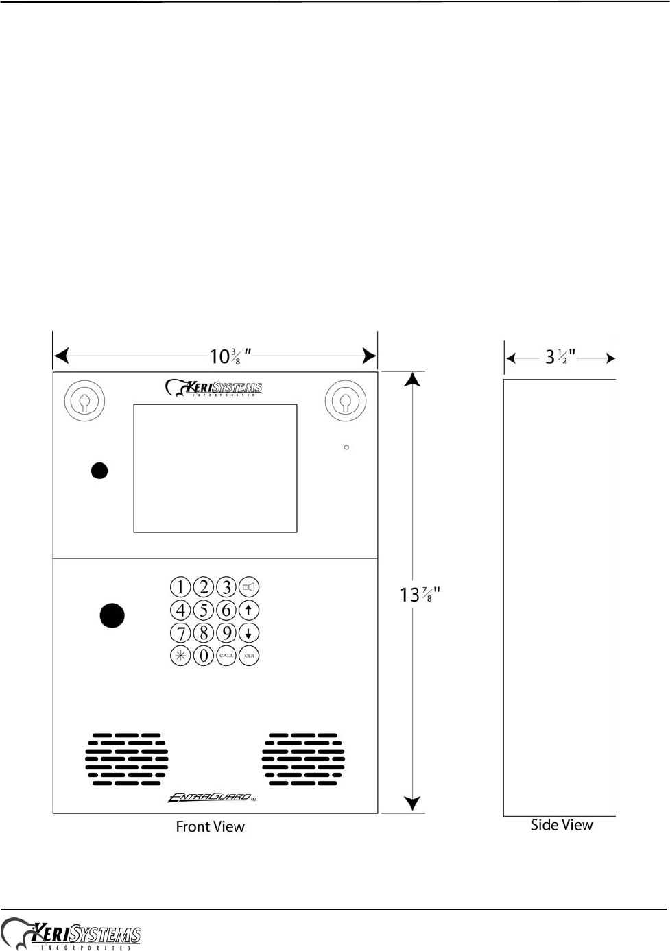
1.1 EntraGuard Platinum Front Panel
Figure 1: The EntraGuard Platinum Telephone Entry Controller - Front Panel
EntraGuard® Platinum Telephone Entry Controller
Quick Start Guide
Page 2 of 28 P/N: 01969-001 Rev. C
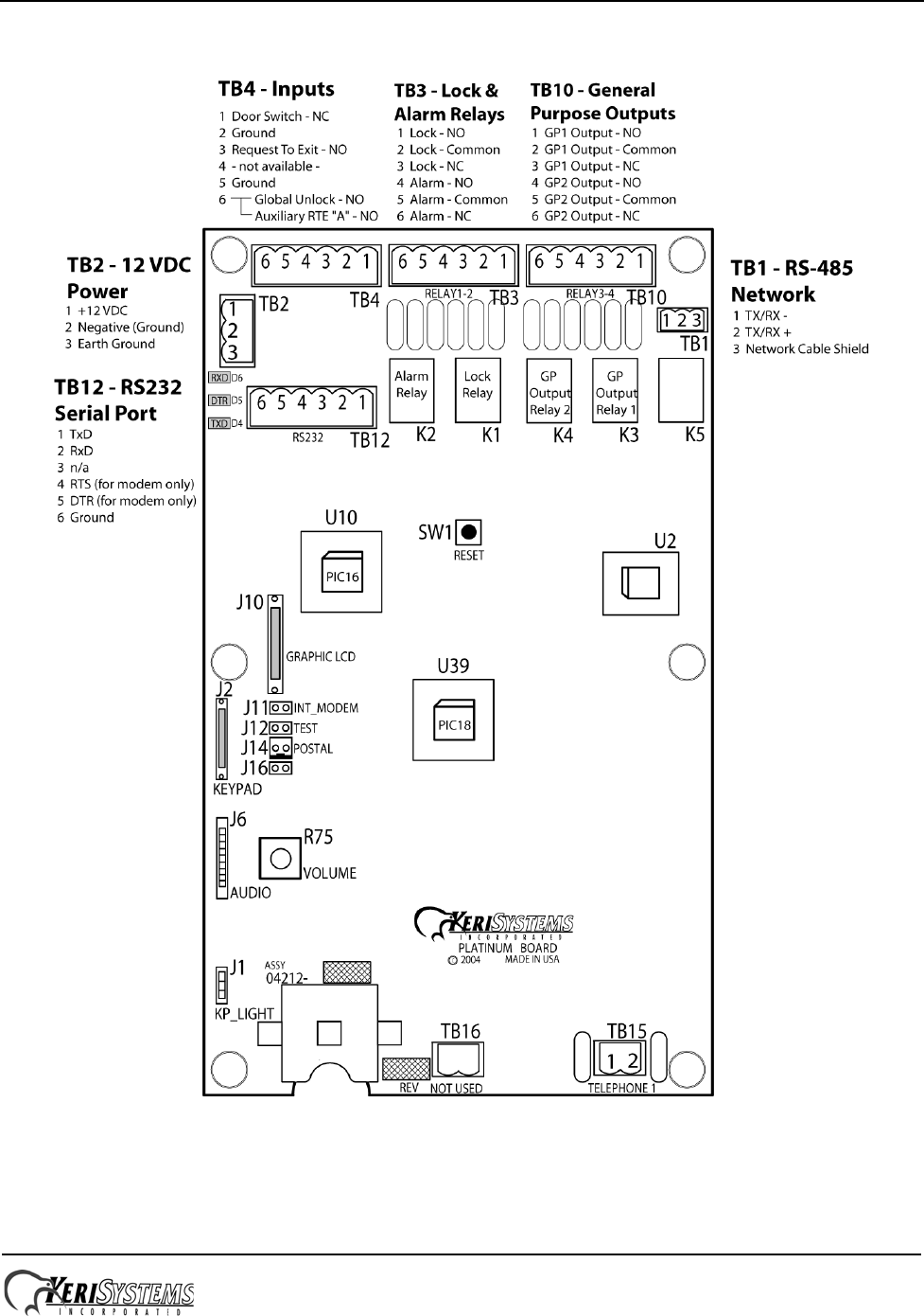
1.2 Platinum Telephone Entry Controller
Figure 2: The Platinum Telephone Entry Controller
NOTE: You must power down the unit before attempting to make or remove any connections. Failure to do so may
damage the controller.
EntraGuard® Platinum Telephone Entry Controller
Quick Start Guide
Page 3 of 28 P/N: 01969-001 Rev. C
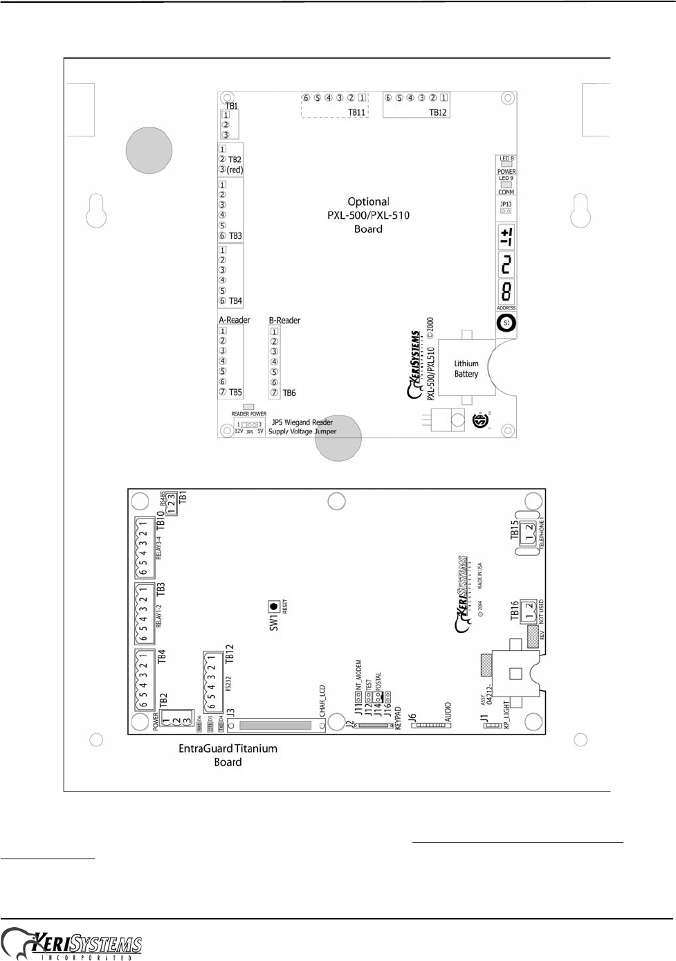
1.3 Board Placement With the PXL-500/PXL510 Board
Figure 3: Platinum Board Placement with the Optional PXL-500/PXL510 board
NOTE: For information on the optional PXL-500/PXL-510 board, see the PXL-500/PXL-510 Quick Start Guide
(P/N 01918-001).
EntraGuard® Platinum Telephone Entry Controller
Quick Start Guide
Page 4 of 28 P/N: 01969-001 Rev. C
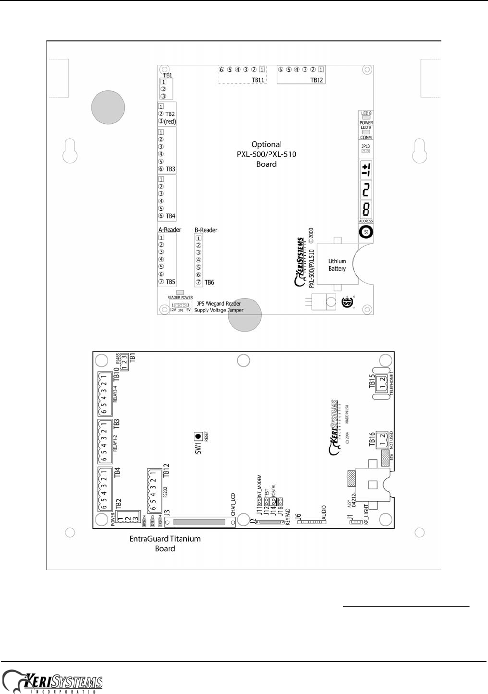
1.4 Board Placement - With the PXL-500G-1 Board
Figure 4: Platinum Board Placement With the Optional PXL-500G-1 Board
NOTE: For information on the optional PXL-500G-1 board and gate control, see the PXL-500G-1 Quick Start Guide
(P/N 01532-001).

EntraGuard® Platinum Telephone Entry Controller
Quick Start Guide
Page 5 of 28 P/N: 01969-001 Rev. C
2.0 Specifications
Unit Dimensions (nominal)
• 13 7/8 inches high by 10 3/8 inches wide by 3 1/2 inches deep, including hinges
• (35 cm by 27 cm by 9 cm)
Operating Temperature/Humidity Range
• -20°F to 140°F (-29°C to 60°C)
• 0% to 90% Relative Humidity, non-condensing
Controller Power Requirements
• 12 VDC @ 1 A (Platinum controller ONLY)
• 12 VDC @ 2 A (Platinum with optional PXL controller)
Current Draw (for Platinum controller ONLY)
• maximum current draw 750 mA for a controller
NOTE: If an electronic locking device (such as a magnetic lock, a door strike, or similar device) is to be driven by the
same power supply as the EntraGuard Platinum controller, please ensure the power supply provides enough current to
drive every device connected to that supply plus an adequate safety margin. AC power cannot be used.
NOTE: Isolation of power supplies may be required with high transient situations.
Controller Memory Retention
• 5 year lithium battery back up to support controller RAM and real-time clock
Output Relay Contact Rating
• 1 Amp @ 24 VDC
Output Device Configuration - 4 Outputs
• Lock Relay Form C
• Alarm Relay Form C
• Auxiliary Relay #1
Auxiliary Relay #2
Input Device Configuration - 3 Inputs
• Door Sense normally closed
• Request to Exit normally open
• Global Unlock normally open (on master only), or
Auxiliary RTE A-Door normally open
Users Allowed
• 5,000 tenants maximum
Event Storage Capacity
• 3,640 events

EntraGuard® Platinum Telephone Entry Controller
Quick Start Guide
Page 6 of 28 P/N: 01969-001 Rev. C
3.0 Cable Requirements
RS-232 Serial Cable
• three conductor, shielded, stranded, AWG 24 wire (Belden 9533 or a larger gauge)
• 50 foot maximum length (per RS-232 industry specification - greater lengths are not recommended)
RS-485 Network Cable
• one twisted, shielded pair of conductors, stranded, AWG 24 wire (Belden 9501 or a larger gauge)
• 4,000 foot total network length (per RS-485 industry specification)
• extended network configurations are possible – refer to the Network Wiring Application Note (P/N 01824-002) for
extended network configurations of up to 5,000 feet per star line and 16,000 feet total network length
Telephone
• 1 pair copper phone line
NOTE: EntraGuard Platinum is not to be used with a Centrex, PBX, or digital phone line. Only use a Plain Old
Telephone Service (POTS) analog phone line.
Input Power
• two conductor, stranded, AWG 18 wire (Belden 8461 or a larger gauge)
NOTE: On long power cable runs, the cable resistance causes a drop in voltage at the end of the cable run. Be sure your
power supply does provide 12 VDC at the end of the cable run. Power supply should be measured under full load (with the
unit attached and all other devices connected).
Earth Ground
• Single conductor, AWG 18 wire (or a larger gauge)1
Input and Output Connections
• two conductor, stranded, AWG 22 (or a larger gauge)
NOTE: The Lock Output relay may require a heavier gauge of wire depending upon the current demands of the lock and
the length of the lock wiring run.
NOTE: If plenum cable is required, please reference the Belden plenum equivalent to the cables listed above.
1. Ground wire is green, with or without yellow tracer.

EntraGuard® Platinum Telephone Entry Controller
Quick Start Guide
Page 7 of 28 P/N: 01969-001 Rev. C
4.0 When Installing Controllers
DO
• since this is a telephone entry system at least one phone line will be necessary, it is important to plan ahead to meet
power and telephone requirements for your system (if using a modem, the host computer will need 1 phone line, plus
one for each master controller in each network or each EntraGuard unit)
• mount controllers in environmentally suitable areas - the EntraGuard Platinum unit is weather resistant, but care
should be taken to avoid areas of weather/temperature/humidity extremes (use the sun/weather shield when mounting
outside)
• mount the controller at least 3 feet away from the controller's power supply to prevent EMI radiated from the power
supply from affecting the controller
• use the enclosure as a mounting template to mark drilling holes for permanent mounting
• note the locations of the knockouts in the enclosures and remove the appropriate knockout for the easiest cable
routing into the controller
• route all controllers in a network in a single, continuous daisy-chain
• route cables in accessible areas for ease of maintenance
• connect all controllers to a quality earth ground1
• add transient suppression across electric devices attached to a controller output
• use an isolation relay (P/N IRP-1) if attaching to a parking gate, a turnstile, an elevator, or any application using a
large electric motor or equivalent voltage/current rated relay
• verify the controller's supply voltage is 12 VDC – long power line runs cause a drop in voltage at the end of the run
DO NOT
• make modem phone line connections through PBX telephone switching systems - most modems are not compatible
with PBX systems leading to disconnection problems with the modem
• locate the EntraGuard Platinum controller near EMI sources - EMI sources can affect the performance of the
controller
• use switching power supplies - they are EMI sources
• route network cables beside power cables - transients on the power cables may be picked-up by network and reader
cables
• stretch or over-tension cables
• route over sharp objects
• let the wires get tangled
• route the EntraGuard Platinum controller as a slave to a PXL-250 master
• route all controllers in a network in spur, hub, or loop configurations
• connect earth ground1 to the network cable shield - the EntraGuard Platinum automatically connects earth ground to
the shield at one point on the network to prevent ground loops
• use gender changer plugs when making RS-232 serial communication connections (unless you know it is a "straight-
through" plug) - gender changers may have internal wiring changes that can disrupt communications
1. Ground wire is green, with or without yellow tracer.
EntraGuard® Platinum Telephone Entry Controller
Quick Start Guide
Page 8 of 28 P/N: 01969-001 Rev. C
5.0 Wiring Instructions
Refer to Figure 2 on page 2 for all wiring connections.
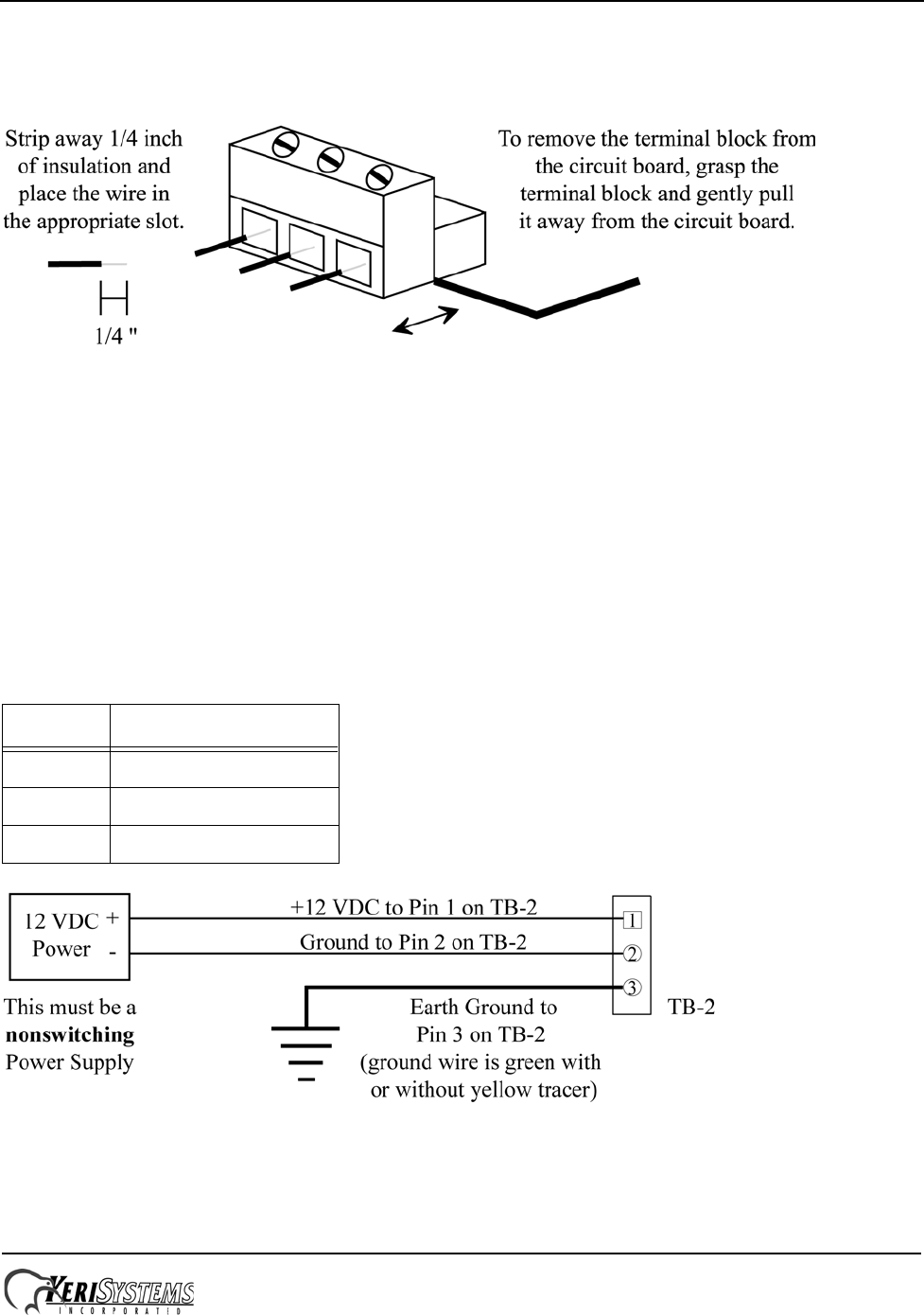
5.1 Terminal Blocks
Figure 5: Connecting Wires and Removing Terminal Blocks
NOTE: Screws on terminal blocks must be tightened securely.
5.2 Connecting the Earth Ground and the 12 VDC Power
The EntraGuard Platinum panel requires 12 VDC power at 750 mA. You must make a quality earth ground connection to
the controller prior to connecting the DC power lines. The earth ground provides protection for the controller and ensures
the best possible operating conditions. Possible sources for earth ground are a ground rod, a cold water pipe, a steel
building frame, the electrical system ground at the breaker/fuse box, or the telephone system ground. The earth ground
connection should be located as close as possible to the EntraGuard Platinum controller. Use the information in Table 1
and Figure 6 to make the earth ground and power connections.
Figure 6: Earth Ground and 12 VDC Power Connections
NOTE: The grounding wire should be a minimum of 14 gauge.
Table 1: Earth Ground and Power
Connections
TB-2 Pin Description
1 + 12 VDC Power Line
2 - 12 VDC Power Line
3 Earth Ground
EntraGuard® Platinum Telephone Entry Controller
Quick Start Guide
Page 9 of 28 P/N: 01969-001 Rev. C
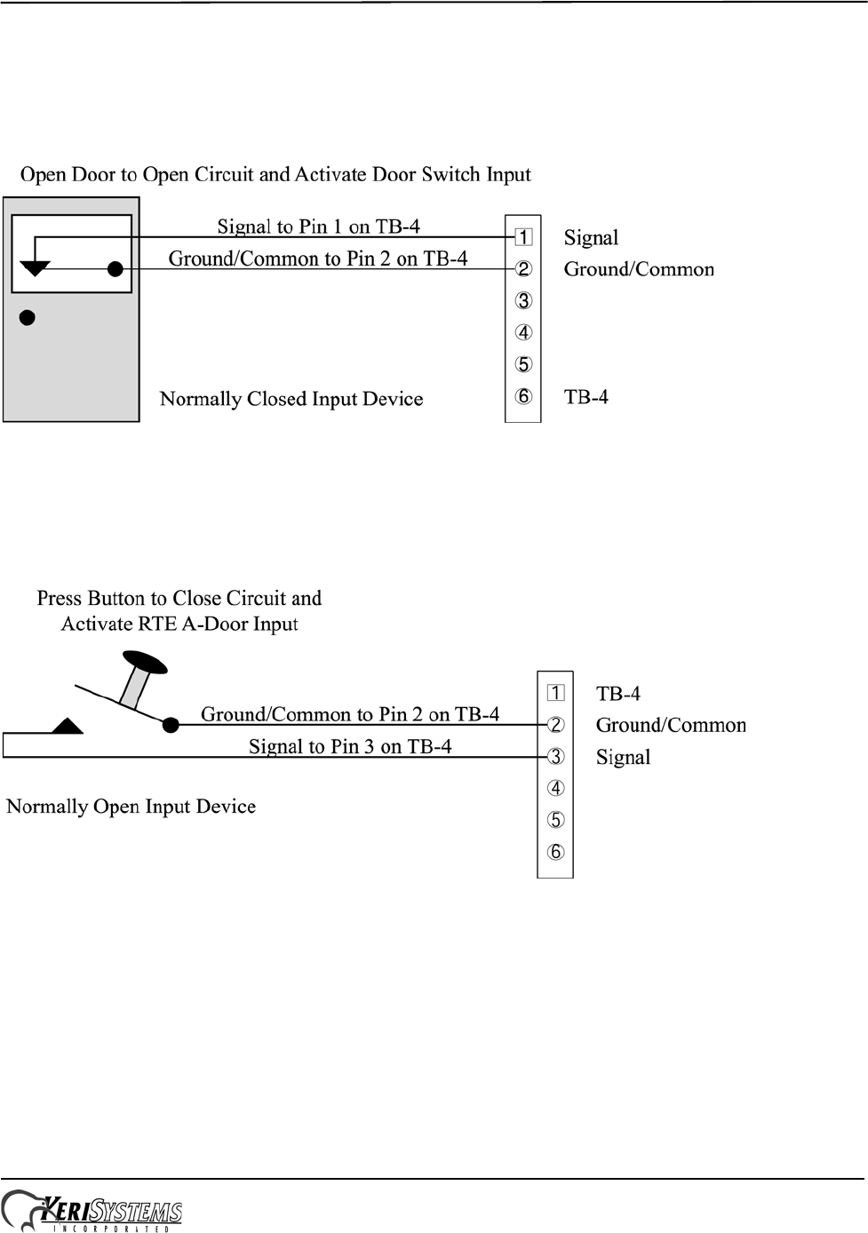
5.3 Connecting a Door Status Input
Each EntraGuard Platinum controller is shipped with an installation kit including all necessary terminal blocks and
transorbs. One of these terminal blocks has a jumper across pins 1 and 2. This terminal block is designated for use on TB-
4. If a door switch is not used on the controller, this jumper prevents a continuous door open status alarm from being
received by the controller. If a door switch is used, simply remove this jumper and install the door switch leads.
Figure 7: Door Status Input Connections
5.4 Connecting a Request to Exit (RTE) Input
Figure 8: Request to Exit Input Connections
EntraGuard® Platinum Telephone Entry Controller
Quick Start Guide
Page 10 of 28 P/N: 01969-001 Rev. C
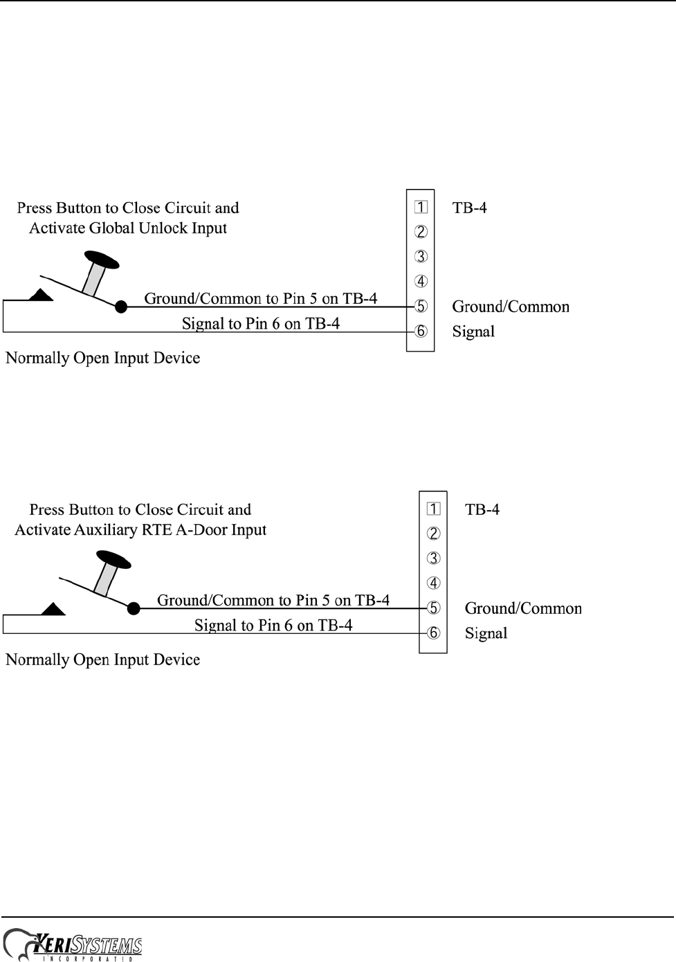
5.5 Connecting a General Purpose Input
The general-purpose input is used in conjunction with the programmable input/output feature of the Doors access control
software. There are two possible uses for the general-purpose input.
• the master controller may be configured for either Global Unlock (see Figure 9) or Auxiliary A-door RTE (see Figure
10)
• the slave unit can only be configured for Auxiliary A-door RTE (see Figure 10)
Make the following connections for a Global Unlock input. (For a master controller only.)
Figure 9: Global Unlock Input Connections
Make the following connections for an Auxiliary RTE A-door input.
Figure 10: Auxiliary A-Door RTE Input Connections
EntraGuard® Platinum Telephone Entry Controller
Quick Start Guide
Page 11 of 28 P/N: 01969-001 Rev. C
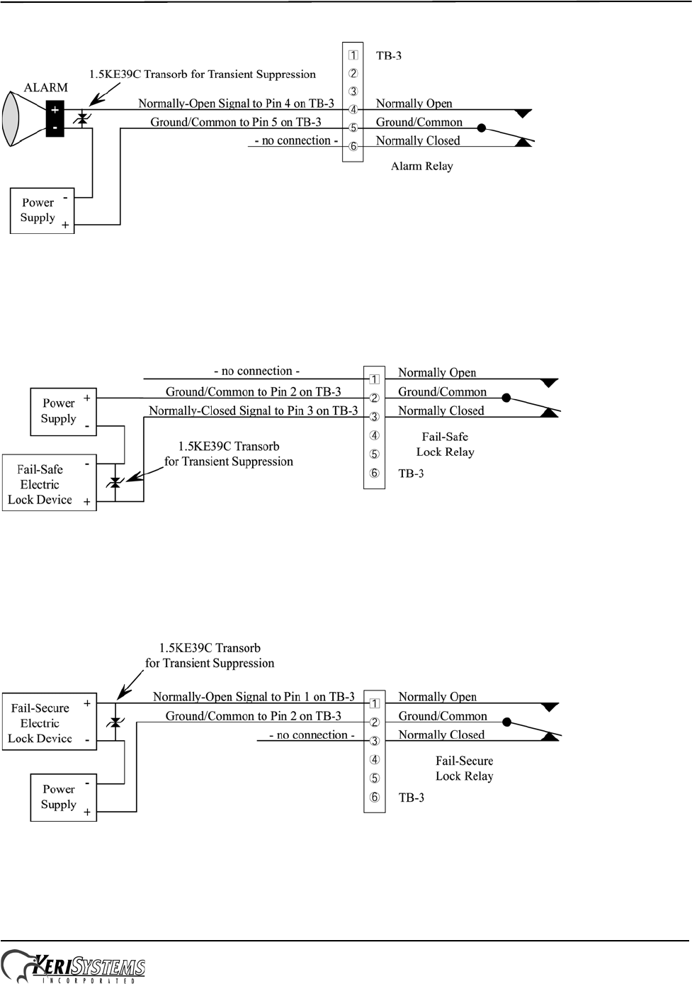
5.6 Connecting an Alarm Output Relay
Figure 11: Alarm Output Relay Connections
5.7 Connecting a Fail-Safe Lock Output Relay
NOTE: The transorb required for transient suppression comes in the EntraGuard Platinum ship kit.
Figure 12: Fail-Safe Lock Output Relay Connections
5.8 Connecting a Fail-Secure Lock Output Relay
NOTE: The transorb required for transient suppression comes in the EntraGuard Platinum ship kit.
Figure 13: Fail-Secure Lock Output Relay Connections
EntraGuard® Platinum Telephone Entry Controller
Quick Start Guide
Page 12 of 28 P/N: 01969-001 Rev. C
6.0 Communication
The communication section handles three different, but related, topics:
• Communication between EntraGuard Platinum controller and tenants
• Communication between the master EntraGuard Platinum controller and the host computer for programming
• Communication between networked EntraGuard Platinum/PXL-500/510 controllers
NOTE: Keri Systems recommends performing a bench test on each unit prior to installation to rule out any phone line
problems.
6.1 Between EntraGuard Platinum Unit and Tenants
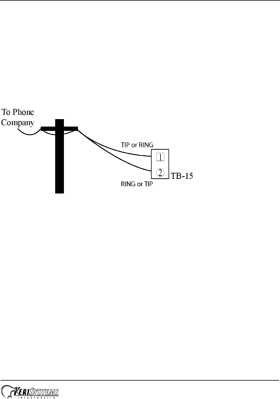
The telephone communication is done via a copper phone line to TB-15. Connect the TIP line to either Pin 1 or Pin 2 then
connect the Ring line to the other Pin (see Figure 14).
Figure 14: TB-15 Phone Line Wiring Connection
There are three ways of connecting the phone line for communication between the EntraGuard Platinum unit and the
tenants.
6.1.1 Single Phone Line for a Single EntraGuard Platinum Unit
For a single EntraGuard Platinum unit, connect the phone line to TB-15 on the EntraGuard Platinum board (see Figure
2 on page 2).
6.1.2 Individual Phone Lines for each EntraGuard Platinum Unit on a Network
The set up for individual phone lines for each EntraGuard unit is the same as for a single phone line for a single
EntraGuard Platinum controller. Each phone line is connected to TB-15 on each EntraGuard Platinum board.
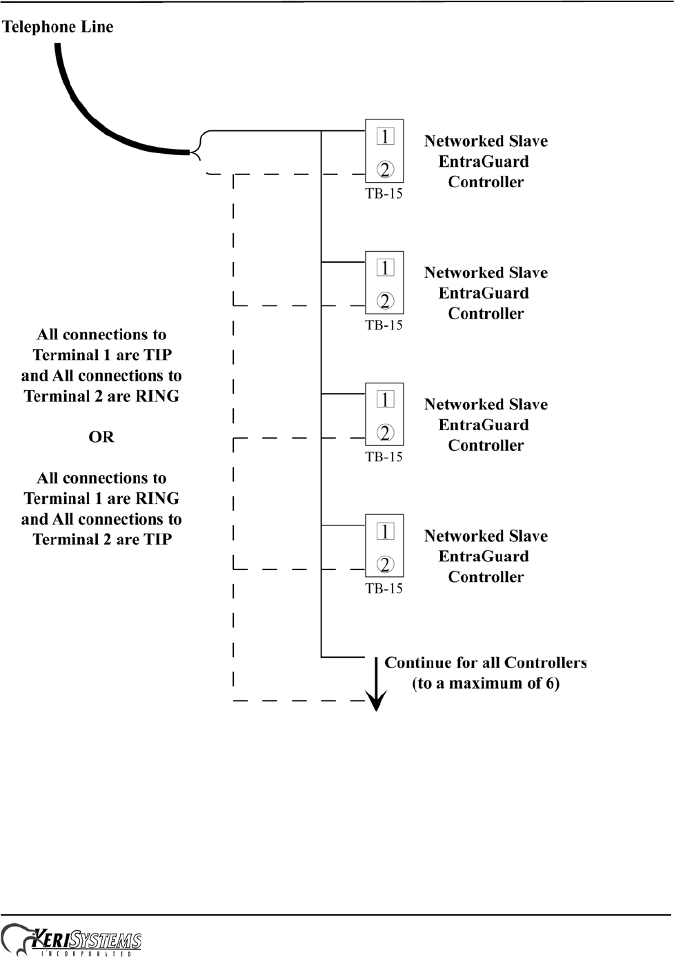
6.1.3 Shared Phone Line for Multiple EntraGuard Platinum Units on a Network
A single phone line may be shared for communication between multiple EntraGuard Platinum units and tenants. The
phone line is plugged into TB-15 on the master EntraGuard Platinum unit with the phone line then going out of the TB-15
phone plug to the next unit’s TB-15 and so on to all the networked EntraGuard units (see Figure 15 on page 13).
NOTE: Sharing a phone line for multiple EntraGuard units is limited to a maximum of 6 units per phone line.
EntraGuard® Platinum Telephone Entry Controller
Quick Start Guide
Page 13 of 28 P/N: 01969-001 Rev. C
Figure 15: Single Phone Line for a Multiple EntraGuard Platinum Unit Network
EntraGuard® Platinum Telephone Entry Controller
Quick Start Guide
Page 14 of 28 P/N: 01969-001 Rev. C
6.2 Between EntraGuard Network and Host Computer
A communication link between the EntraGuard network and the host computer is provided via one of two ways.
• using the phone line connected to TB-15
• using the RS-232 serial port
NOTE: In order for monitor mode to work, the RS-232 serial port method must be used (see Section 6.2.2 on page 15).
NOTE: If a PXL controller is connected to the EntraGuard, it may be used as the master controller for communication
which will free up the phone line. For further information on communication alternatives, see either the PXL-500/PXL-
510 Quick Start Guide (P/N 01918-001) or the PXL-500G-1 Quick Start Guide (P/N 01532-001).
6.2.1 Phone line (Internal Modem)
The EntraGuard Platinum controller’s internal modem may be used for communication between the master controller and
an external modem1 connected to the host computer. To use the EntraGuard’s internal modem, attach the phone line to
TB-15 located on the master controller’s board (see Figure 2 on page 2).
NOTE: If you are using two separate phone lines, one for communication with the tenants and one for programming, you
will not be able to use the internal modem for programming and must use an external modem connected to the RS-232 as
described in Section 6.2.2.2 on page 17.
Once the phone line has been attached, the J11 jumper must be set for proper operation. When using TB-15 phone line
connection for communication with the host computer, place the jumper on the INT_MODEM jumper (see J11 on Figure
2 on page 2).
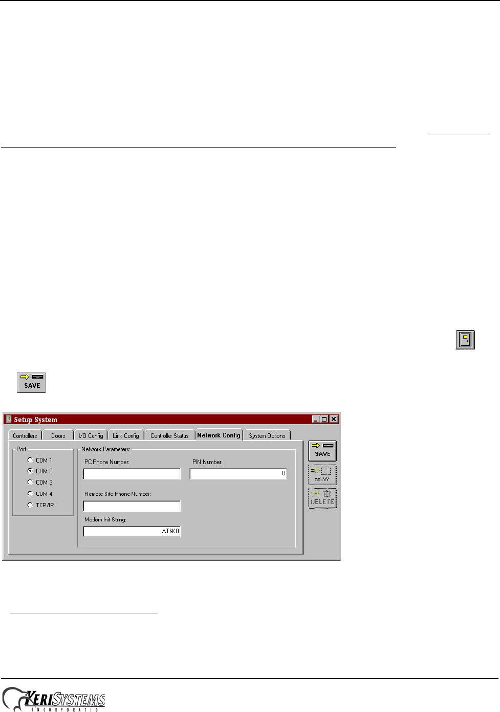
The Doors software must also be configured for using the internal modem. In the Doors software, click on the
button, then select the Network Config tab. In the “Modem Init String” field type in AT&K02 (see Figure 16). Click on
the button.
Figure 16: Modem Init String Set
NOTE: For wiring of an external modem to the host computer, see Section 6.2.3 on page 19.
1. You must use a Keri Systems modem for proper communication.
2. Although it is not necessary to enter this code with every type of modem, Keri Systems recommends you
enter it in all situations for proper communication between the master controller and the host computer.

EntraGuard® Platinum Telephone Entry Controller
Quick Start Guide
Page 15 of 28 P/N: 01969-001 Rev. C
6.2.2 RS-232 Serial Port
Using the RS-232 serial port for communication between the EntraGuard unit and the host computer may be done one of
two ways:
• by direct connect (maximum of 50 feet)
• through an external modem.
For either of these options, the INT_MODEM J11 jumper should not have a jumper across it. Verify there is no jumper set
across J11 (see Figure 2 on page 2) when using the RS-232 serial port for communication.
NOTE: Do not use male/female gender changer plugs or 25-pin to 9-pin adapters when making RS-232 serial port
connections. These devices may have internal wiring changes that can disrupt communications when implemented in
conjunction with the Keri Systems serial wiring instructions. If you must use a gender changer plug, ensure it is a
“straight-through” plug.
NOTE: When using 56K modems to communicate with remote access control networks, all modems must use the same
communication format - either X2 or Flex. Incompatibilities between the two formats make some modems of one format
incapable of reliable communication with modems of the competing format. Modems using the V.92 specification are
compatible regardless of whether they are from an X2 or Flex manufacturer. See http://www.v92.com/ for more
information.
EntraGuard® Platinum Telephone Entry Controller
Quick Start Guide
Page 16 of 28 P/N: 01969-001 Rev. C
6.2.2.1 Direct Serial Connection – Controller to PC
To make the connection between the EntraGuard master controller and the host computer you will use one cable.
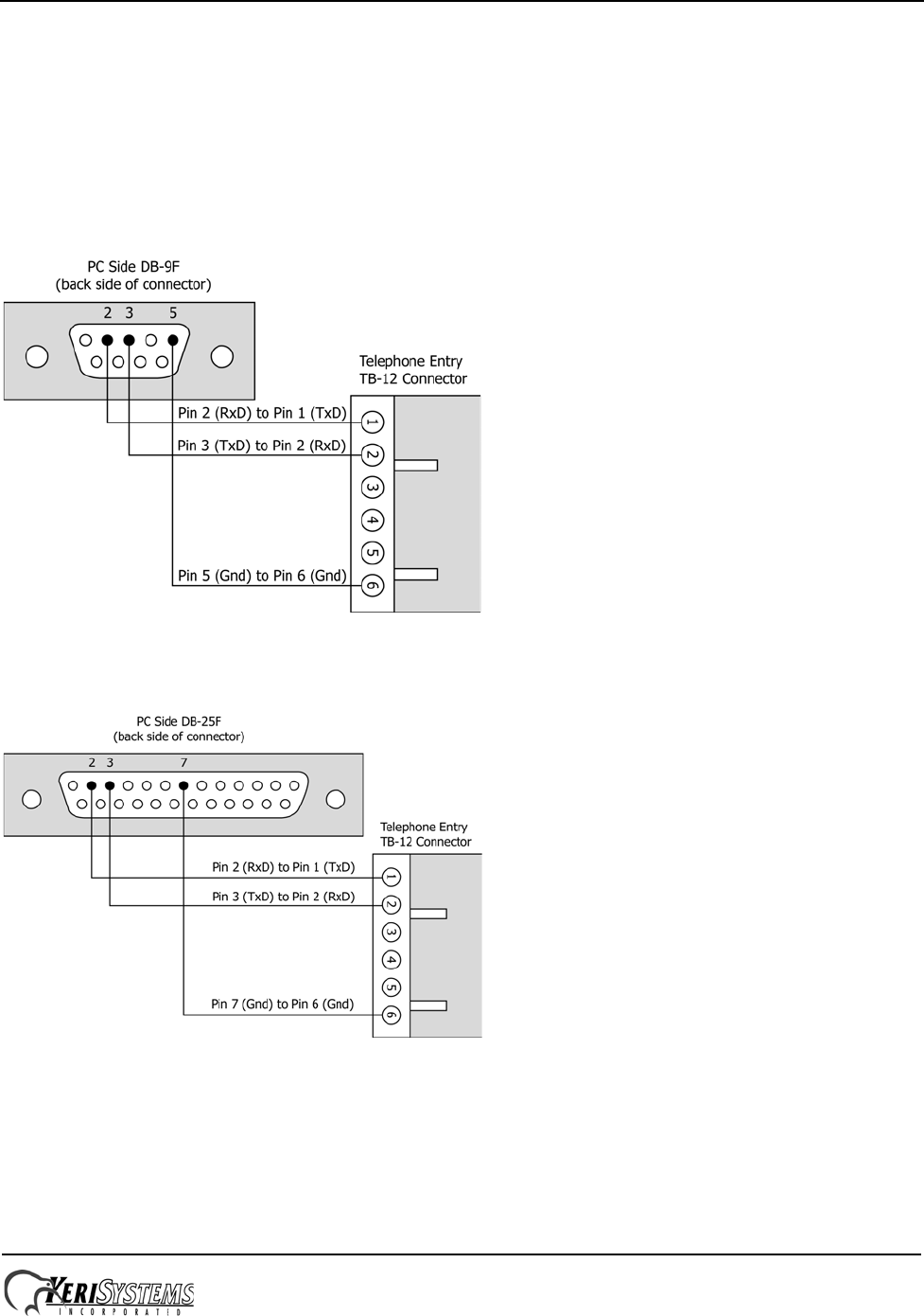
• If the host computer has a male DB-9 connector on the serial port, you must use a Keri Systems KDP-552 cable or
create a cable according to the drawing in Figure 17.
• If the host computer has a male DB-25 connector on the serial port, you must use a Keri Systems KDP-251 cable or
create a cable according to the drawing in Figure 18 on page 16.
The Keri Systems part number for this cable is KDP-552.
Figure 17: PC/DB-9F to Telephone Entry/TB-12 RS-232 Direct Serial Connections
The Keri Systems part number for this cable is KDP-251.
Figure 18: PC/DB-25F to Telephone Entry/TB-12 RS-232 Direct Serial Connections
EntraGuard® Platinum Telephone Entry Controller
Quick Start Guide
Page 17 of 28 P/N: 01969-001 Rev. C
6.2.2.2 Modem to Controller
To make the connection between the master controller and the host computer you will use two cables: one between the
host computer and its modem (see Section 6.2.3 on page 19), and one between the master controller and its modem.
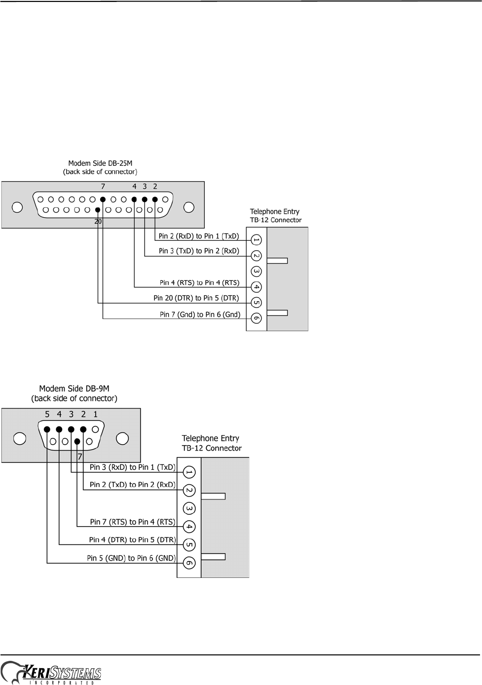
• If the modem has a female DB-25 connector, you must use a Keri Systems KDP-336 cable or create a cable as shown
in Figure 19.
• If the modem has a female DB-9 connector, you must create a cable as shown in Figure 20.
• If the modem was purchased from Keri Systems, it comes with an adapter that accommodates a female DB-9
connector (should the modem have a DB-9 instead of a DB-25 connector). Use this adapter cable in conjunction with
a KDP-336 cable to make the modem/controller connection. See Figure 21 on page 18.
The Keri Systems part number for this cable is KDP-336.
Figure 19: Modem/DB-25M to Telephone Entry/TB-12 Serial Port Connections
The Keri Systems part number for this cable is KDP-929M.
Figure 20: Modem/DB-9M to Telephone Entry/TB-12 Serial Port Connection
EntraGuard® Platinum Telephone Entry Controller
Quick Start Guide
Page 18 of 28 P/N: 01969-001 Rev. C
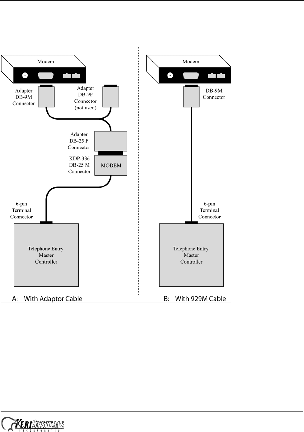
6.2.2.3 Modem Cable Connection
• An adapter cable is provided, when needed, with a modem purchased from Keri Systems. Connect the adapter cable
between the modem and the KDP-336 cable as shown in side A of Figure 21.
• To use the KDP-929M cable see side B of Figure 21.
Figure 21: Modem Cable Connection
EntraGuard® Platinum Telephone Entry Controller
Quick Start Guide
Page 19 of 28 P/N: 01969-001 Rev. C
6.2.3 Modem to PC Serial Connection
Keri Systems does not provide this cable. It is an off-the-shelf item from any computer supplier or electronics store, and
its configuration is dependent upon the configuration of the serial port on the host computer. Based on the serial port, there
are four possible cables.
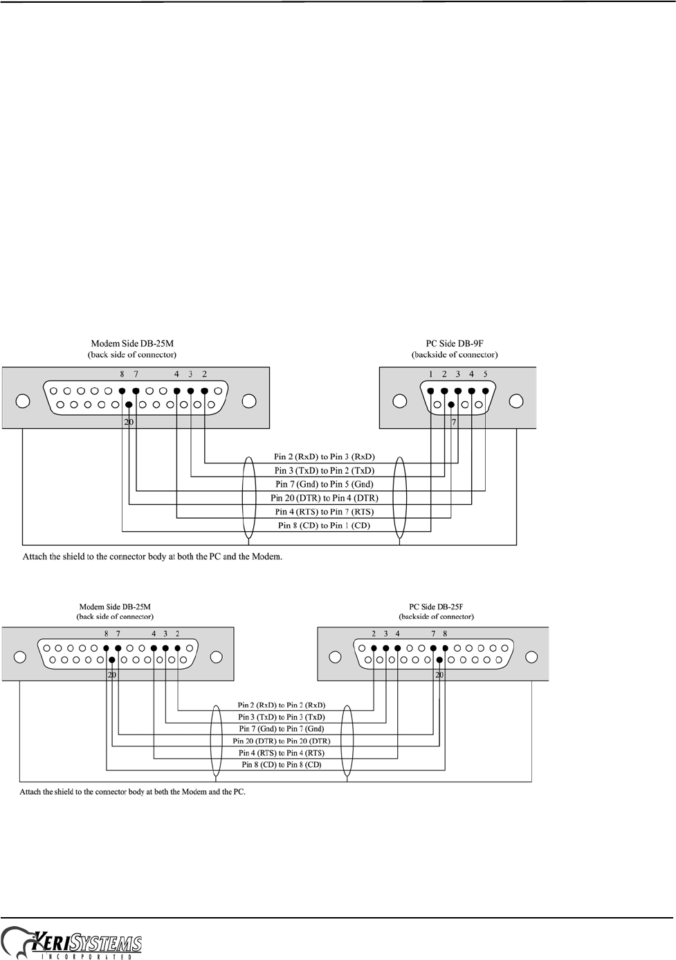
• If the modem has a male DB-25 connector and the host computer’s serial port has a female DB-9 connector, purchase
or create a cable as shown in Figure 22.
• If the modem has a male DB-25 connector and the host computer’s serial port has a female DB-25 connector,
purchase or create a cable as shown in Figure 23.
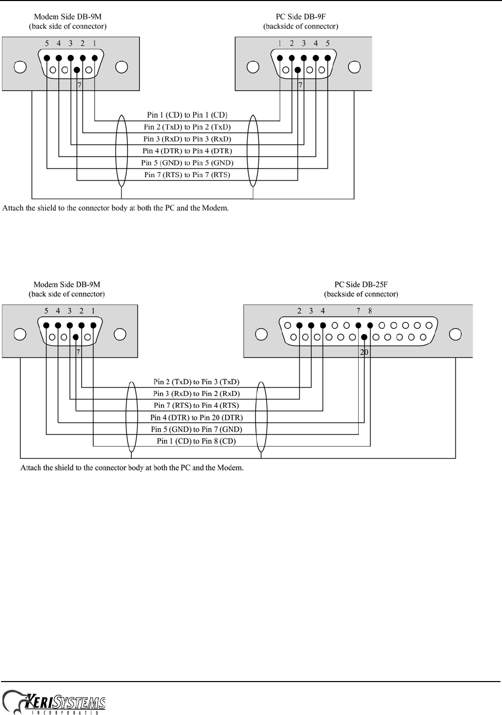
• If the modem has a male DB-9 connector and the host computer’s serial port has a female DB-9 connector, purchase
or create a cable as shown in Figure 24 on page 20.
• If the modem has a male DB-9 connector and the host computer’s serial port has a female DB-25 connector, purchase
or create a cable as shown in Figure 25 on page 20.
NOTE: Keri Systems requires using modems from the same manufacturer at both the host computer and the access control
network. This eliminates the possibility of incompatibilities between modems from two different manufacturers from
affecting the communication between access control network and host computer. Keri Systems cannot be held responsible
for problems caused by incompatibilities between modems from two different manufacturers.
Figure 22: Modem/DB-25M to PC/DB-9F PC Serial COM Port Connection
Figure 23: Modem/DB-25M to PC/DB-25F PC Serial COM Port Connection
EntraGuard® Platinum Telephone Entry Controller
Quick Start Guide
Page 20 of 28 P/N: 01969-001 Rev. C
Figure 24: Modem/DB-9M to PC/DB-9F PC Serial COM Port Connection
Figure 25: Modem/DB-9M to PC/DB-25F PC Serial COM Port Connection
EntraGuard® Platinum Telephone Entry Controller
Quick Start Guide
Page 21 of 28 P/N: 01969-001 Rev. C
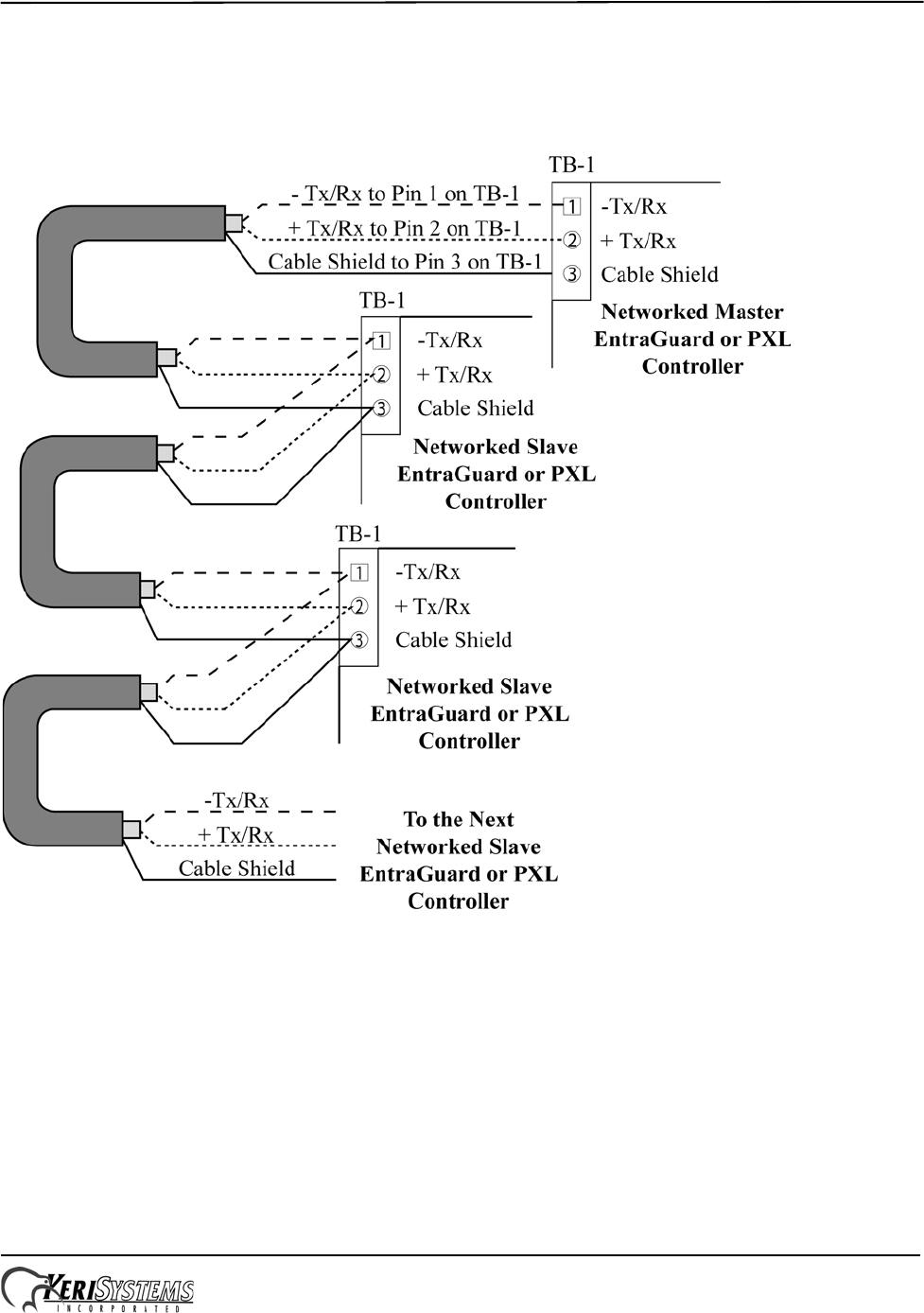
6.3 Network Communication
6.3.1 RS-485 Access Control Network Connection
The following figure shows how to connect more than one controller to the access control network.
Figure 26: RS-485 Network Connections
EntraGuard® Platinum Telephone Entry Controller
Quick Start Guide
Page 22 of 28 P/N: 01969-001 Rev. C
7.0 Powering the Controller for the First Time
NOTE: Verify the earth ground has been connected at pin 3 of TB-2 before turning the power on for the first time.
7.1 Verify the 12 VDC Supply Voltage
To verify the 12 VDC supply voltage:
1. Turn system power on.
2. Set the DVM to a DC volt scale capable of reading 12 VDC.
3. Place the Red DVM lead on Pin 1 of TB-2.
4. Place the Black DVM lead on Pin 2 of TB-2.
5. Check the DVM reading. It should read +12 VDC +/- 2 volts.
If the DVM does not read 12 VDC (+/- 1.5 V), verify the power supply is of the correct voltage, verify the cable length
does not exceed 200 feet, and verify the cable gauge is AWG 18.
NOTE: On long power cable runs, keep in mind the resistance in the cable itself causes a drop in voltage at the end of the
run. The power supply must be able to account for this voltage drop.
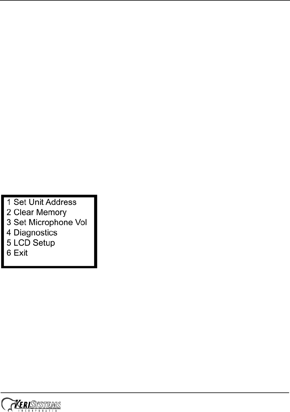
8.0 Setup Controller
If you're turning system power on for the first time, certain tasks must be performed prior to entering access control
information from Doors. On the EntraGuard Platinum main board (see Figure 2 on page 2), hold the Reset Button (SW1)
down and turn the controller’s power on. After the controller beeps once, indicating the controller’s firmware is ready for
programming, release the SW1 button. The LCD on the front panel will display the Reset Menu (see Figure 27). From this
menu you may perform different tasks such as set the controller’s address, clear the controller’s memory, set the
microphone gain, check diagnostics, and set the LCD font.
Figure 27: Reset Menu
NOTE: If no keys have been selected within 60 seconds, the unit will time out and go directly to the default message. In
order to reach the Reset Menu, the unit must be powered up again.
EntraGuard® Platinum Telephone Entry Controller
Quick Start Guide
Page 23 of 28 P/N: 01969-001 Rev. C
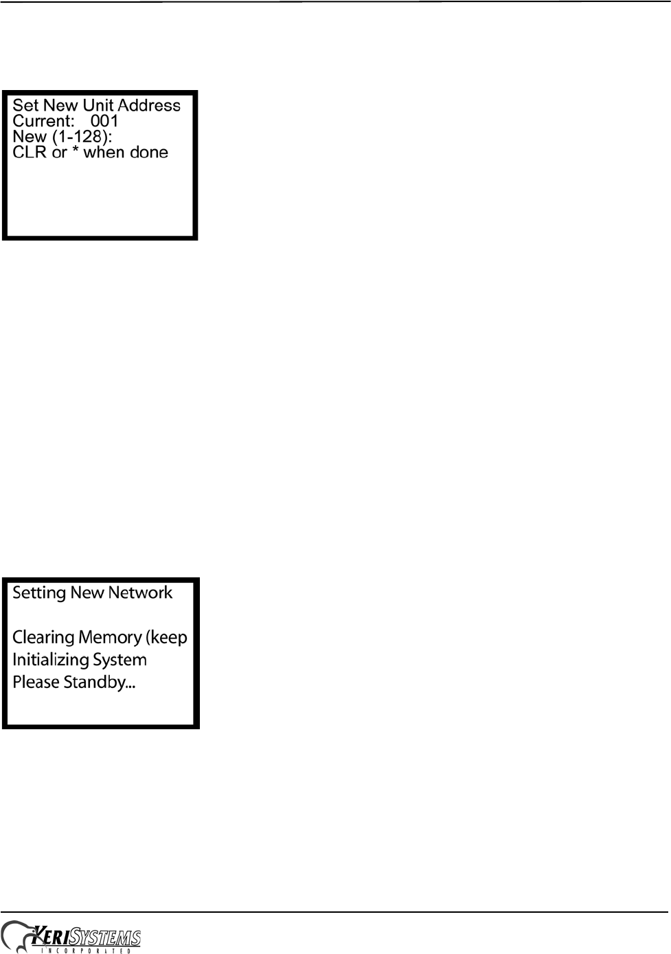
8.1 Set Unit Address
The controller’s address may only be set through the Reset Menu. To set the desired operating address for the controller,
press 1 on the keypad. The Set New Unit Address screen appears on the LCD (see Figure 28).
Figure 28: Set Unit Address
The address range is from 1 to 128. The Master Controller must be set to address 1. Other slave EntraGuard/PXL-500/510
controllers may be assigned any number from 2 to 128. If the network is made up of PXL-250s, the EntraGuard Platinum
must be set as the Master.
If the address shown as Current is correct, you may either enter the same address and press *, or just press * to return to
the reset menu. If you do not enter a new address, or enter the same address that is already assigned to this unit, you will
need to clear the memory separately (see “Clear the Controller’s RAM’’ on page 24).
NOTE: Changing the address of an EntraGuard Platinum controller completely erases all information within the
controller. It is vitally important that you collect all data from the controller before changing the address. Once the
address is changed (and the RAM is automatically cleared) the information in the controller is lost and cannot be
recovered.
If the address shown as Current needs to be changed, enter the new address by pressing the numbers on the keypad. The
number selected will show in the New line. If you enter the wrong number, simply press CLEAR to erase what has been
entered. When you are satisfied with the address entered, press *. If you have changed the number from what is shown as
Current, the controller will automatically clear the memory as it changes the address (see Figure 29).
Figure 29: Setting New Address
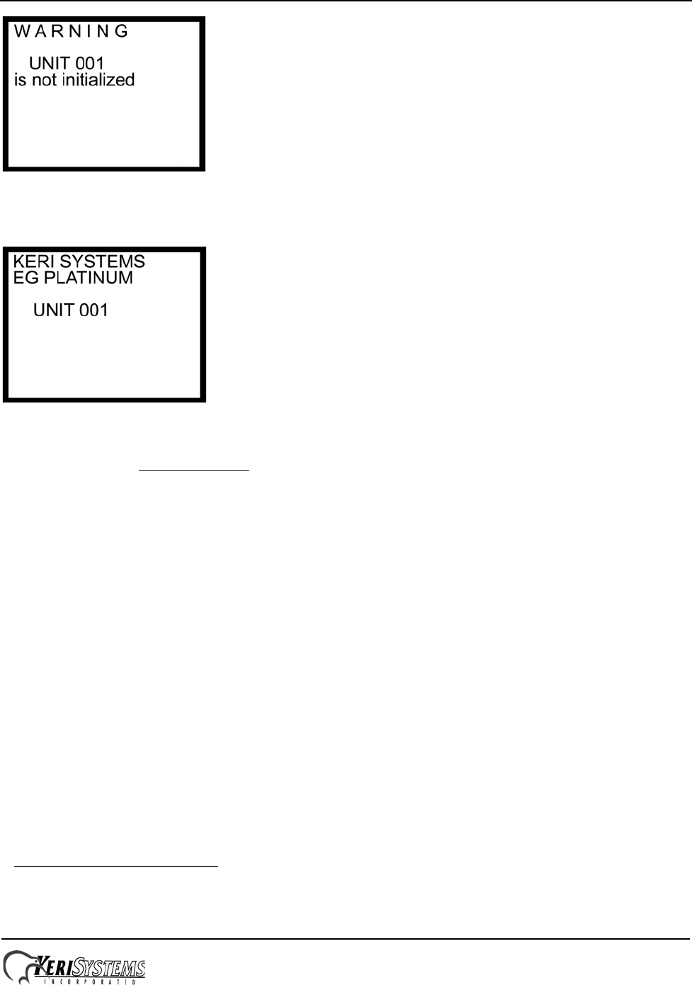
Once the memory has been cleared, the unit is ready to be configured. The LCD will display a warning that the unit has
not been initialized (see Figure 30 on page 24). This display will rotate with the EntraGuard Default display (see Figure
31 on page 24) until a Total Update from Doors has been performed on the unit. Once an update has been performed, only
the default will be displayed.
EntraGuard® Platinum Telephone Entry Controller
Quick Start Guide
Page 24 of 28 P/N: 01969-001 Rev. C
Figure 30: Not Initialized Unit Warning
NOTE: Any time the “Not Initialized Unit Warning” appears on the LCD display, the unit needs a Doors update.
Figure 31: EntraGuard Platinum Default LCD Display
NOTE: The default display will remain until a message banner has been created (for instructions on how to create a
message banner see the Doors Users Guide - P/N 01914-100).
8.1.1 The Master Controller1
The Master Controller must be set to address 1 so that all slave controllers on the access control network can identify the
master controller. For the Master Controller to correctly identify all slave controllers on the network, one of two things
must be done.
1. The master controller must be the last unit on the network to be powered on. This ensures that when the Master
Controller begins polling the network to see what slave units are connected for system configuration, all slave units
are ready to communicate their unique addresses and their configuration information.
2. The Auto-Configuration routine within the Doors program must be run. This instructs the Master Controller to poll
all controllers on the network for addresses and configuration information.
NOTE: An auto-configuration must be performed any time changes are made to the 485 network.
8.2 Clear the Controller’s RAM
When turning system power on for the first time, the controller’s memory needs to be cleared of any spurious information
that may be in the RAM. If you changed the controller address, the memory is automatically cleared. However, if you did
not change the address, you will need to clear the controller’s RAM separately. From the Reset Menu (see Figure 27 on
page 22), press 2 to Clear Memory. The Clear Memory screen will appear on the LCD (see Figure 32 on page 25).
1. The EntraGuard Platinum Controller must be installed as the Master Controller only in a mixed EntraGuard/
PXL-250 network.
EntraGuard® Platinum Telephone Entry Controller
Quick Start Guide
Page 25 of 28 P/N: 01969-001 Rev. C
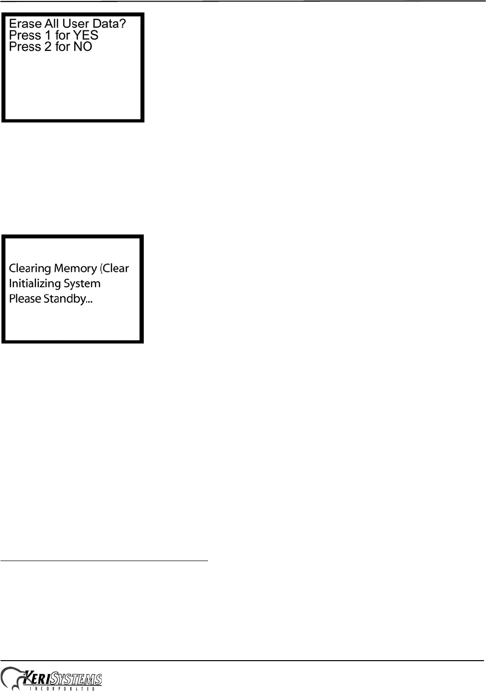
Figure 32: Clear Memory
From the Clear Memory Screen you may either:
1. Press 1 to clear the controller’s RAM. The LCD will change to show the memory is being cleared (see Figure 33).
Once the controller’s RAM has been cleared, the unit is ready for use. The LCD will rotate between the Initialization
Warning and EntraGuard Default screens (see Figure 30 on page 24 and Figure 31 on page 24) until a Total Update
from Doors has been performed on the unit.
Figure 33: Clearing Memory
OR
2. Press 2 to return to the Reset Menu without clearing the controller’s RAM.
NOTE: Clearing the system RAM completely erases all information within the EntraGuard Platinum controller, except for
the controller address. If there is any information in system RAM from an access control installation and the system RAM
is cleared, the information in the controller is lost and cannot be recovered.
8.3 Set Microphone Volume
The EntraGuard controller comes with the microphone gain set for proper operation. The Set Microphone Vol menu
option is not used at this time.
8.4 Diagnostics and Troubleshooting
For information regarding the diagnostics screens and troubleshooting the EntraGuard Platinum Controller, see the
EntraGuard Troubleshooting and Diagnostics Guide (P/N 01912-001).
EntraGuard® Platinum Telephone Entry Controller
Quick Start Guide
Page 26 of 28 P/N: 01969-001 Rev. C
8.5 LCD Setup
The EntraGuard LCD (located on the front of the EntraGuard Platinum controller) is capable of using two different font
sizes. The default is set for the large size. However, if the small size font would be preferred as the default, it may be
changed through the reset menu. From the Reset Menu (see Figure 27 on page 22), press 5 for LCD Setup. The LCD
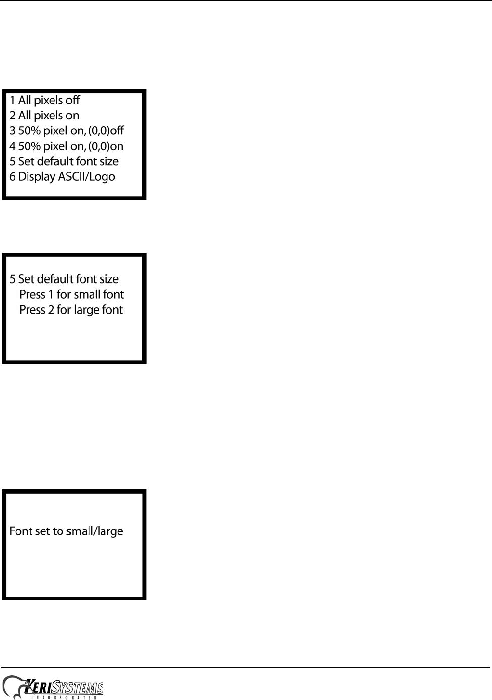
Setup menu will appear on the LCD (see Figure 34).
Figure 34: Setup LCD Menu
1. Select 5 on the keypad to change the default font size. The Set Font Default Menu appears (see Figure 35).
Figure 35: Set Font Default Menu
2. Press 1 to make the default font small.
3. Press 2 to make the default font large.
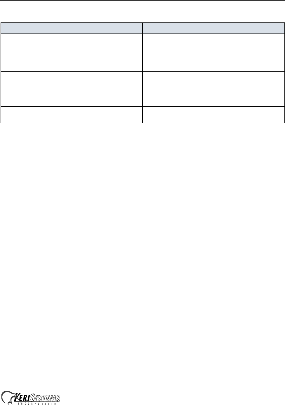
NOTE: Users may temporarily change the font size when using the EntraGuard Platinum controller, but any changes
made will always return to the default as selected here.
4. Once the font size is selected a Font set to small/large window appears (see Figure 36).
Figure 36: Font Set

EntraGuard® Platinum Telephone Entry Controller
Quick Start Guide
Page 27 of 28 P/N: 01969-001 Rev. C
9.0 General Information on Inputs
A controller input detects a state change generated by a device outside the controller that may prompt a response from the
controller. Input devices that generate a state change may be normally closed or normally open. This section provides a
brief description of normally closed versus normally open inputs.
9.1 Normally-Closed
A normally closed input device continually keeps a circuit active or complete. A state change is generated when the
normally closed input device is forced open, breaking the circuit. In an access control system, a door switch is a typical
example of a normally closed device. While the door remains closed, the switch remains closed. When someone opens the
door, the door switch is opened, breaking the circuit and generating a state change. The controller then responds to the
state change and generates an output (such as sounding an alarm if the door is a secure door).
9.2 Normally-Open
A normally open input device continually leaves a circuit open, or incomplete. A state change is generated when the
normally open input device is forced closed, completing the circuit. In an access control system, a request-to-exit (RTE)
button is a typical example of a normally open device. In an access control installation, an RTE button is located on the
secure side of a door. While there is no one there pressing the button, the switch remains open. When someone desires to
exit through a secure door, they press the RTE button, closing the circuit and generating a state change. The controller
then responds to this state change and generates an output (such as unlocking the door to allow egress).
10.0 General Information on Safety versus Security with Door Locks
When installing a door lock there are two things to consider: safety versus security, or should the door be “fail-safe” or
“fail-secure”.
10.1 Fail-Safe Door Lock
Fail-safe means that if the power should fail at a door (perhaps due to a power outage or equipment failure), the door will
automatically unlock allowing entrance or egress. Power is required to keep the door locked. A fail-safe door ensures
people will be able to enter and exit a secured area through that door in the case of an emergency. A typical fail-safe
application may use a magnetic lock. In this application, the controller energizes the lock relay, causing the lock relay to
change its state. In its new state the normally closed circuit is opened breaking the power to the magnetic lock and
allowing the door to be opened.
10.2 Fail-Secure Door Lock
Fail-secure means that if the power should fail at a door (perhaps due to a power outage or equipment failure), the door
will automatically lock and not allow entrance but will continue to allow egress. Power is required to unlock the door. A
fail-secure door ensures a secured area remains secure regardless of the situation. A typical fail-secure application may
use a door strike. In this application, the controller energizes the lock relay, causing the lock relay to change its state. In its
new state the normally open circuit is closed activating the release mechanism for the door strike on the door to be
opened.
EntraGuard® Platinum Telephone Entry Controller
Quick Start Guide
Page 28 of 28 P/N: 01969-001 Rev. C
11.0 Contact Keri Systems
End of document.
Keri USA Keri UK, Ireland, Europe
2305 Bering Drive
San Jose, CA 95131 Unit 17
Park Farm Industrial Estate
Ermine Street
Buntingford
Herts SG9 9AZ UK
Telephone: (800) 260-5265
(408) 435-8400 Telephone: + 44 (0) 1763 273 243
Fax: (408) 577-1792 Fax:+ 44 (0) 1763 274 106
Web: www.kerisys.com Web:www.kerisystems.co.uk
E-mail: sales@kerisys.com
techsupport@kerisys.com E-mail:sales@kerisystems.co.uk
tech-support@kerisystems.co.uk
