L 3 Communications CyTerra 25STW4100-019 Low Power Radar User Manual FCC Part 15
L-3 Communications CyTerra Corporation Low Power Radar FCC Part 15
Manual

3998 FAU Blvd. Suite 310 Boca Raton, FL 33431 Tel: 561-961-5585 Fax: 561-961-5587
Certification Exhibit
FCC ID: YKD-25STW4100-019
FCC Rule Part: CFR 47 Part 90, DA 09-2482
ACS Project: 13-2037
Manufacturer: L-3 Communications CyTerra Corporation
Model: Range-R 2D
User Manual
TB X-XXXX-XXX-XX TB X-XXXX-XXX-XX TB X-XXXX-XXX-XX
FCC COMPLIANCE
WARNING
Do not open the unit. There are
no user serviceable parts
contained within the unit, and
opening or tampering with it will
void the FCC certification and
the manufacturer’s warranty.
This device is approved for use by the FCC
under FCC Order DA 09-2482, FCC ID YKD-
25STW4100-019.
Warning: Changes or modifications to this
device not expressly approved by L-3 CyTerra
could void the user’s authority to operate the
equipment.
“This equipment complies with FCC radiation
exposure limits set forth for an uncontrolled
environment. This equipment may operate in
direct contact with the body of the user under
normal operating conditions. This transmitter
must not be co-located or operating in
conjunction with any other antenna or
transmitter.”
“NOTE: This equipment has been tested and
found to comply with the limits for a Class B
digital device, pursuant to Part 15 of the FCC
Rules. These limits are designed to provide
reasonable protection against harmful
interference in a residential installation. This
equipment generates, uses, and can radiate
radio frequency energy and, if not installed and
used in accordance with the instructions, may
cause harmful interference to radio
communications. However, there is no
guarantee that interference will not occur in a
particular installation. If this equipment does
cause harmful interference to radio or television
reception, which can be determined by turning
the equipment off and on, the user is
encouraged to try to correct the interference by
one or more of the following measures:”
• Reorient or relocate the receiving antenna.
• Increase the separation between the
equipment and receiver.
• Connect the equipment into an outlet on a
circuit different from that to which the receiver
is connected.
• Consult the dealer or an experienced radio/TV
technician for help.
For any questions related to FCC compliance
contact L-3 CyTerra Technical Support.
This RANGE-R 2D Handheld Through Wall
Radar is controlled under the U.S.
International Traffic in Arms Regulations
(ITAR) and may not be exported without
proper authorization by the U.S. Department of
State.
TB X-XXXX-XXX-XX TB X-XXXX-XXX-XX TB X-XXXX-XXX-XX
RADAR SET,
RANGE-R 2D
CONTROLS AND COMPONENTS
1 Hand Grips
2 Battery Cover
3 Scan Buttons
4 Liquid Crystal Display (LCD)
CONTROL SEQUENCE
Function Sequence
Power-On Press and release both Scan Buttons. Sensor
will boot to Scan Mode.
Power-Off Press and hold both Scan Buttons for three (3)
seconds.
Increase Brightness In Scan Mode, press the top Scan button.
Decrease Brightness In Scan Mode, press the bottom Scan button.
Main Menu Press and release both Scan Buttons while in
Scan Mode.
Cycle Menu Options Press the bottom Scan Button while in Menu
Mode.
Select Menu Option Press the top Scan Button while the selection
is highlighted.
Scan Mode Press and release both Scan Buttons from any
other mode or menu.
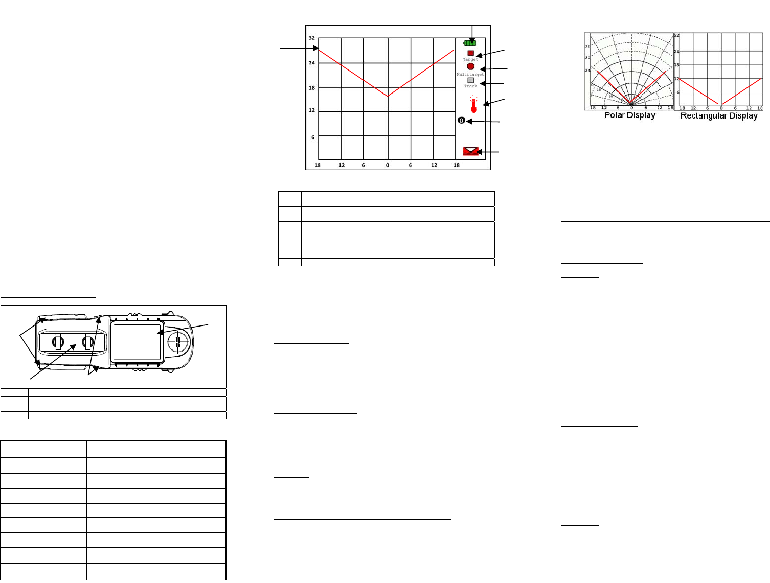
INDICATORS AND SYMBOLS
GRID SELECTION (FROM THE MAIN MENU)
1. Use the bottom Scan Button to cycle through the menu options until GRID
SELECT is highlighted.
2. Use the top Scan Button to select the highlighted option.
3. On the GRID SELECT Menu, use the bottom Scan Button to cycle
through the menu options until the desired option is highlighted.
4. Using the top Scan Button, highlight either the Rectangular or Polar Grid
option.
5. Select BACK to return to the MAIN MENU or both Scan Buttons to resume
operation
VARIABLE FIELD OF VIEW (FOV) SELECTION (FROM THE MAIN MENU)
1. Use the bottom Scan Button to cycle through the menu options until
VARIABLE FOV is highlighted.
2. Use the top scan button to select VARIABLE FOV (the current setting will
be displayed).
OPERATING PROCEDURES
SCAN MODE
1. Hold the sensor horizontally and steadily against a wall. Ensure the
operator and any personnel behind or near the sensor remain as still as
possible. The level of operator movement is displayed in the lower right
corner of the display. Too much movement may cause false alarms or
degradation in detection capabilities.
2. Press and release both Scan Buttons to power on the sensor and begin
scanning. Watch the display for a detection indication. It takes
approximately three seconds to detect a moving target and up to six
seconds to detect a near stationary target. The best detection
performance occurs directly in front of the unit, and extends out ±60
degrees in a conical pattern. Outside this region, detection performance
rapidly falls off to a minimum at ±90 degrees, creating blind spots in close
proximity and at sharp angles from the unit.
3. Whenever possible, repeat the procedure at multiple locations along the
wall surface to ensure accuracy of results and maximize coverage area.
4. Be sure that the first wall in scanning range is visible and is shown at the
correct range on the display
5. The RANGE-R 2D will go into standby mode after 1 minute of scanning.
INTERPRETING RESULTS
Targets are indicated by red squares on the display. Tracking of a target’s
movement is indicated by white squares. Multiple targets too close to interpret as
individual targets, are displayed as a red octagon. The first two walls detected
are indicated with bold red horizontal lines. The current field of view (if FOV
display is set to ON), are two diagonal lines extending from the 0 point on the
readout display. The graphical display uses a grid overlay to show the
approximate distance in meters that a detection is located from the sensor with
the number zero (0) representing the actual location of the sensor. This can be
either on a rectangular grid, which allows for the easy determination of range and
cross range to a plotted target, or a polar grid which allows for easy
determination of distance and direction to a plotted target.
SCAN TIMES
• The minimum amount of time to detect a stationary target (standing
person) is six seconds.
• There is a 2.5 second delay between the real movement and the
displayed results. The object is displayed where it was 2.5 seconds ago.
• Object must be separated by at least 2 meters to be displayed as
separate targets.
A 15 second scan time is recommended before moving.
1
3
4
2
7
INDICATORS AND SYMBOLS
1
2
1 Battery Life indicator
2 Target Symbol
3 Multi-Target Symbol
4 Track Symbol
5 Brightness Level/Over Temp indicator (Replaces Brightness)
6 Number of Targets Displayed
7 Operator Movement Indicator/Backside Motion Indicator
(only one displayed at a time, neither are displayed in normal
operation)
8 Readout Map
PREPARATION FOR USE
SENSOR SET UP
1. Remove the RANGE-R 2D and soft case from the storage container.
2. Remove the RANGE-R 2D from the soft case.
3. Make a visual inspection to ensure there is no external damage to the
housing or LCD screen
BATTERY INSTALLATION
1. Turn both thumbscrews that secure the battery cover counterclockwise to
loosen them and remove the battery cover.
2. Place batteries into the compartment. Place them in the orientation shown in
the internal plastic molding of the compartment.
3. Replace the battery cover. Line the thumbscrews up with their corresponding
holes.
4. Turn the thumbscrews clockwise to tighten and secure the battery cover.
5. DO NOT MIX BATTERIES.
BRIGHTNESS ADJUSTMENT
1. Power on the RANGE-R 2D sensor by depressing and releasing both Scan
Buttons.
2. Hold the RANGE-R 2D sensor horizontally.
3. Press the top Scan Button to increase the brightness and the bottom Scan
Button to decrease the brightness. The brightness level will be represented by
a number between 0 and 255 displayed on the LCD screen.
4. Continue until the desired brightness level is displayed.
MAIN MENU
1. Hold the RANGE-R 2D sensor horizontally and press and release both Scan
Buttons to power the sensor on. The sensor will boot to Scan Mode.
2. While the sensor is in Scan Mode, press both Scan Buttons and release to
enter Menu Mode. The sensor will display the MAIN MENU.
SHUTDOWN TIMEOUT SELECTION (FROM THE MAIN MENU)
1. Use the bottom Scan Button to cycle through the menu options until
SHUTDOWN TIMEOUT is highlighted.
2. Use the top Scan Button to select the highlighted option.
3. On the SHUTDOWN TIMEOUT Menu, use the bottom Scan Button to cycle
through the menu options until the desired option is highlighted.
4. Use the top Scan Button to select the highlighted option.
5. Select BACK to return to the MAIN MENU or both Scan Buttons to resume
operation.
5
3
4
8
6
7
TB X-XXXX-XXX-XX TB X-XXXX-XXX-XX TB X-XXXX-XXX-XX
THINGS TO KEEP IN MIND WHILE OPERATING THE SYSTEM.
This is a motion detector. It will pick up the movement of any object. This
includes but is not limited to:
• The movement of trees and foliage caused by the wind
• Ceiling fans
• Standing fans
• Motors (vehicle or otherwise)
• Vibrating equipment (duct work, compressor, etc)
• Animals
• Friendly personnel (in front or behind the operator)
Any of these moving objects, and others, will appear as targets on the display.
There is no way for the operator to determine this “clutter” from an actual target.
METALLIC SURFACES AND OBJECTS
• Sensor cannot penetrate metal surfaces
• Move sensor and attempt to rescan
• Metallic surfaces behind non-metallic surfaces could also block the
system (refrigerator, file cabinet).
MOISTURE
Moisture content of the structure being scanned will affect the system’s ability to
“see” through the walls. If the surface is saturated, the system may not be able to
detect targets at all.
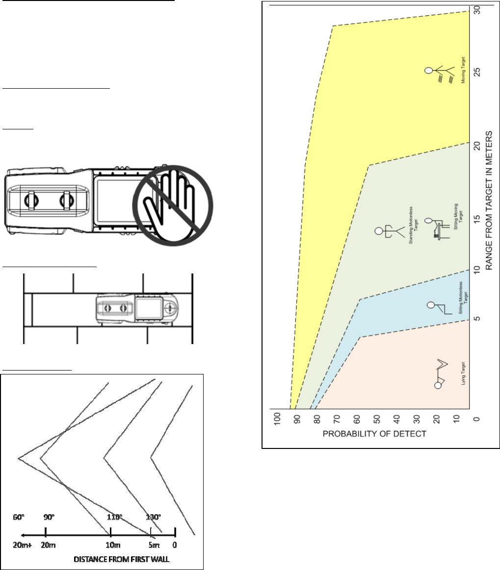
REARWARD LOOKING ANTENNA
DO NOT BLOCK THE REARWARD LOOKING ANTENNA WHEN SCANNING.
System placement on Block walls
Place the system over one block not between two blocks.
Radar Field of View (FOV)