Leonardo S p a TRA100B Part 87 Aircraft Licensed Transmitter operating at 1090MHz User Manual tman 1124 02x
LEONARDO S.p.a. Part 87 Aircraft Licensed Transmitter operating at 1090MHz tman 1124 02x
Contents
- 1. Users manual 1
- 2. Users manual 2
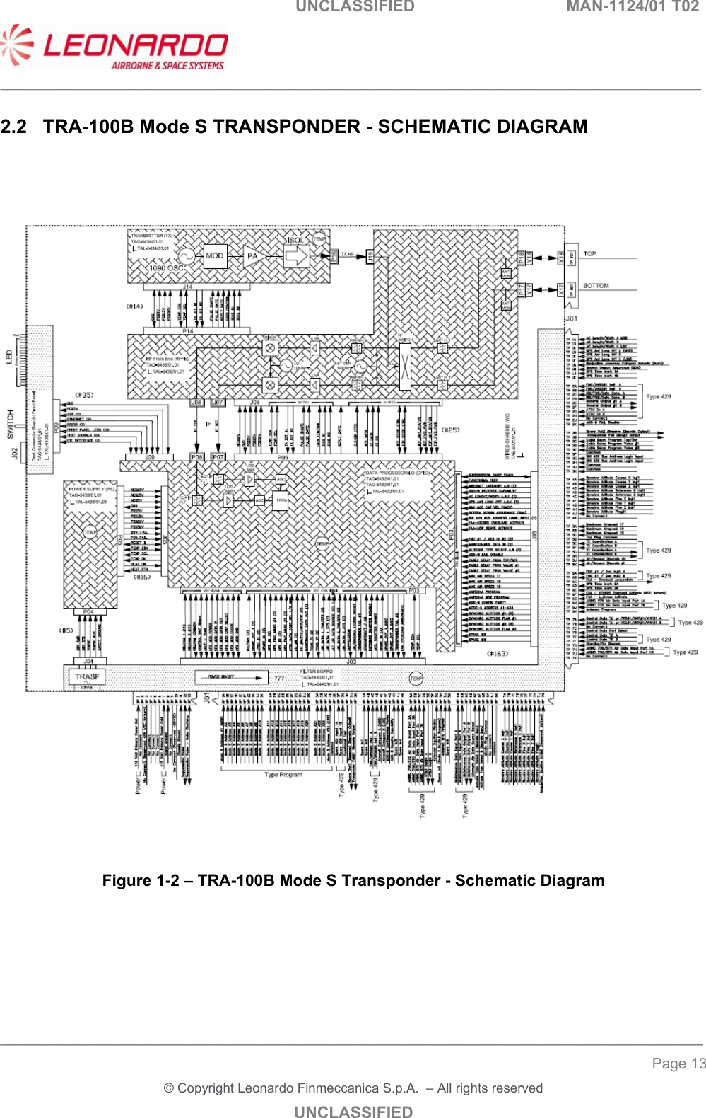
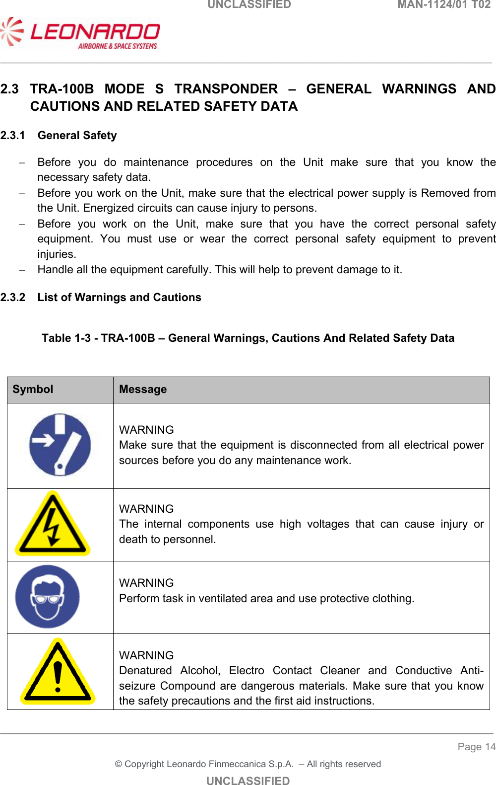
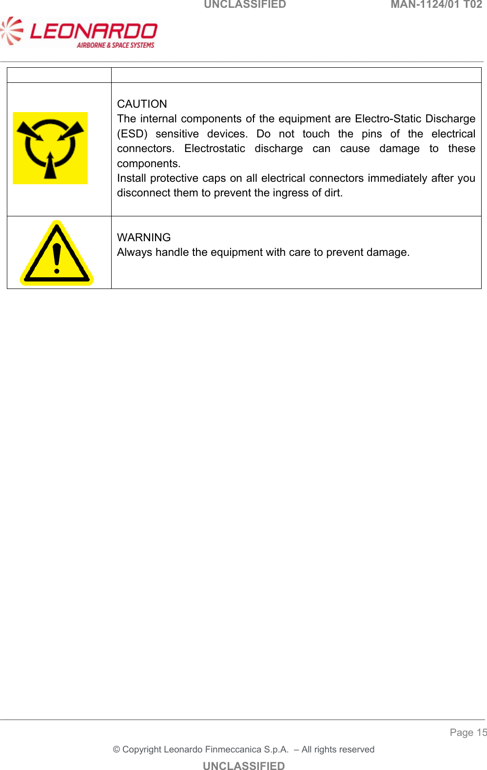
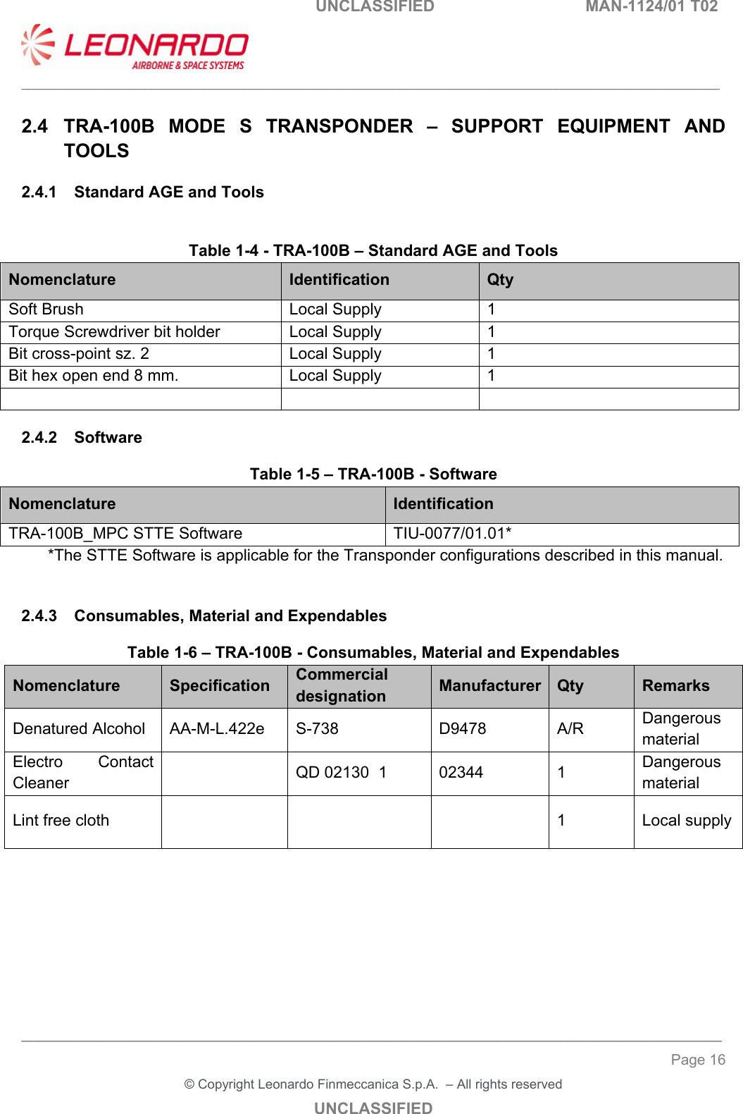
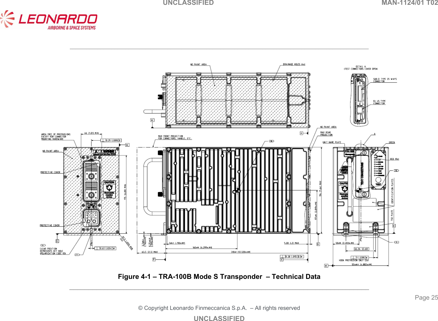
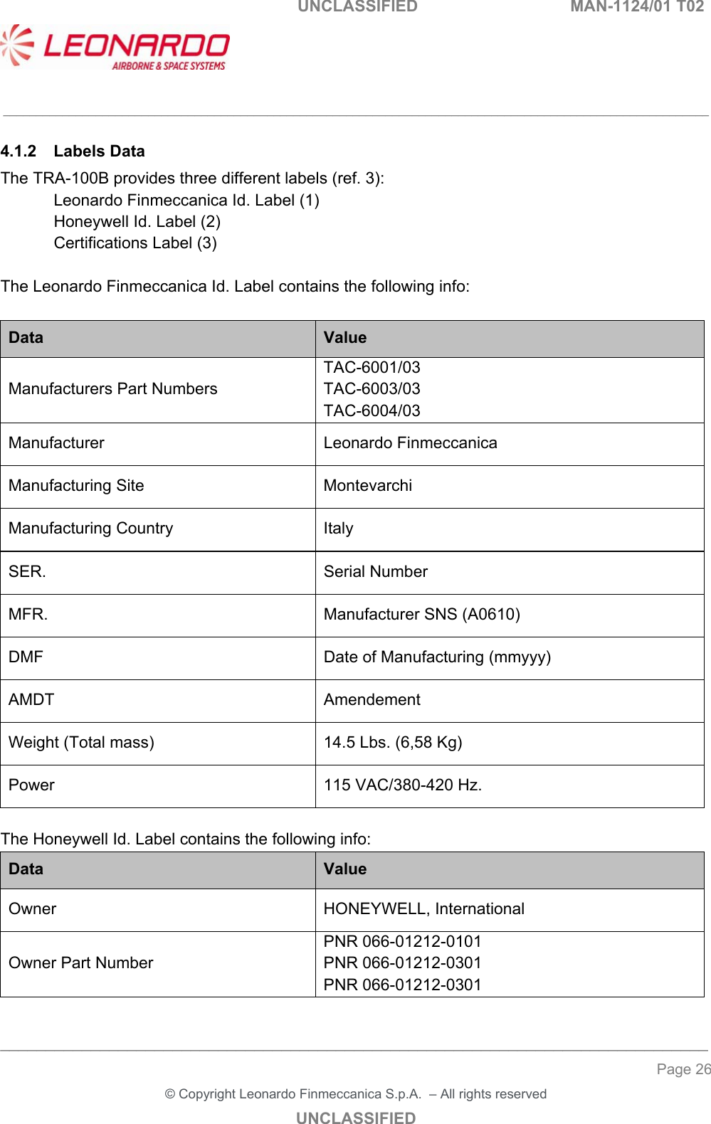
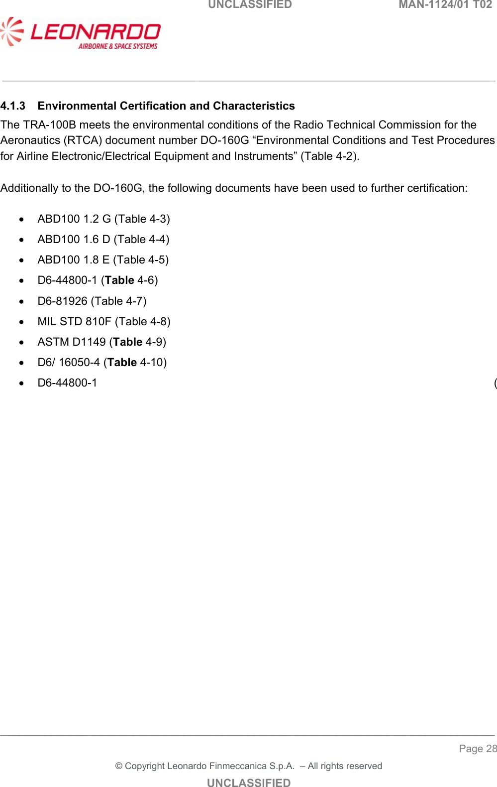
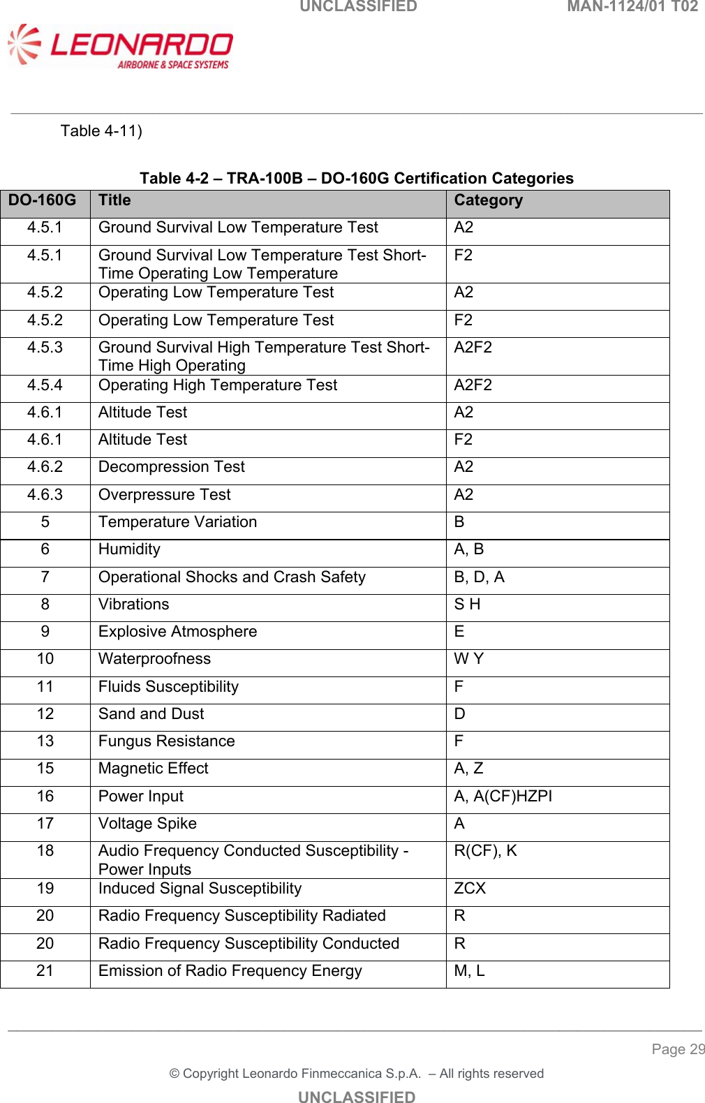
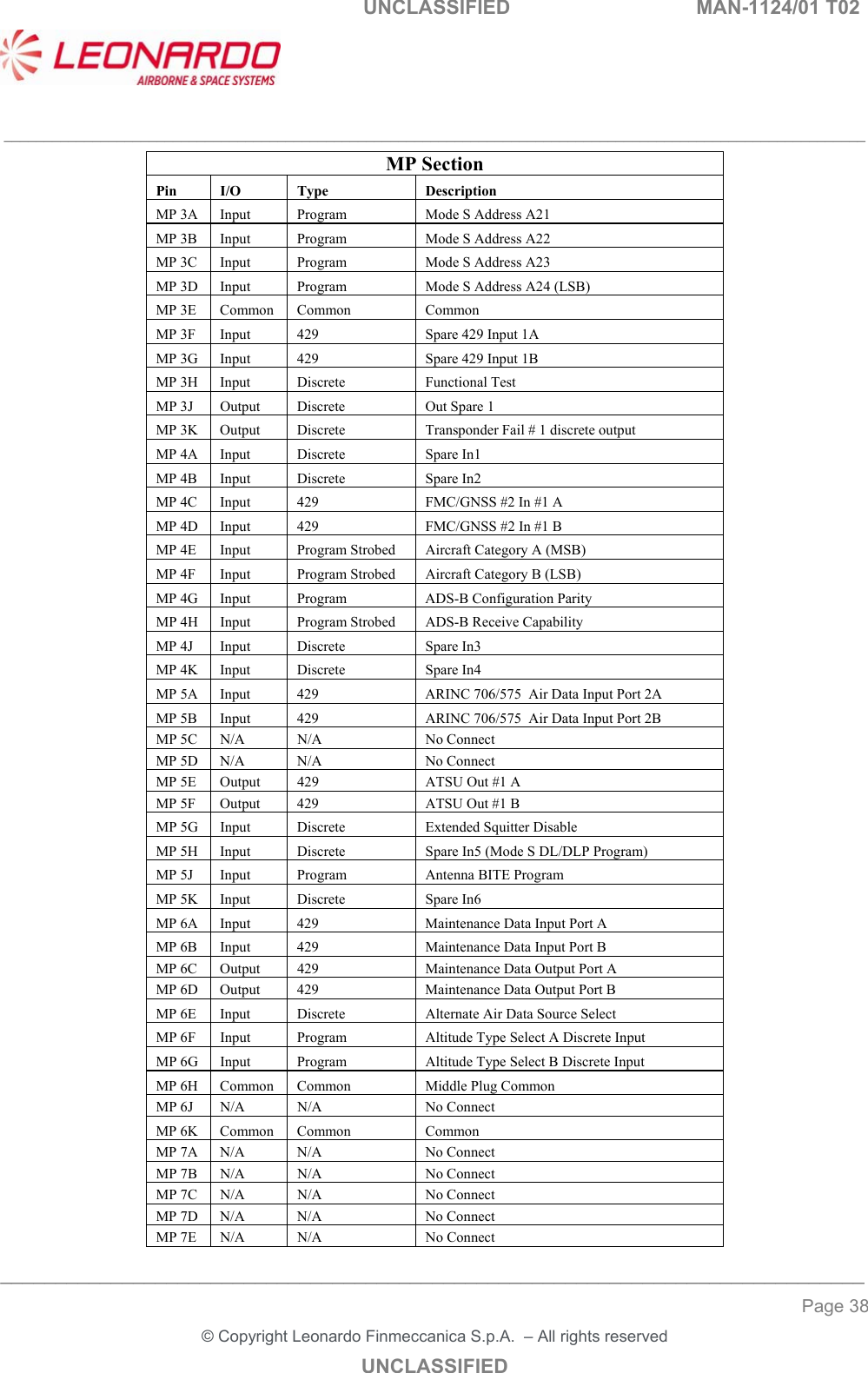
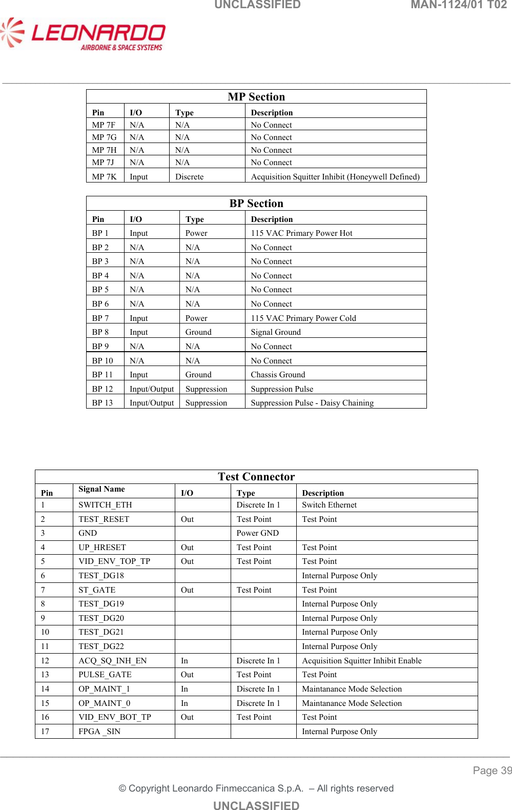
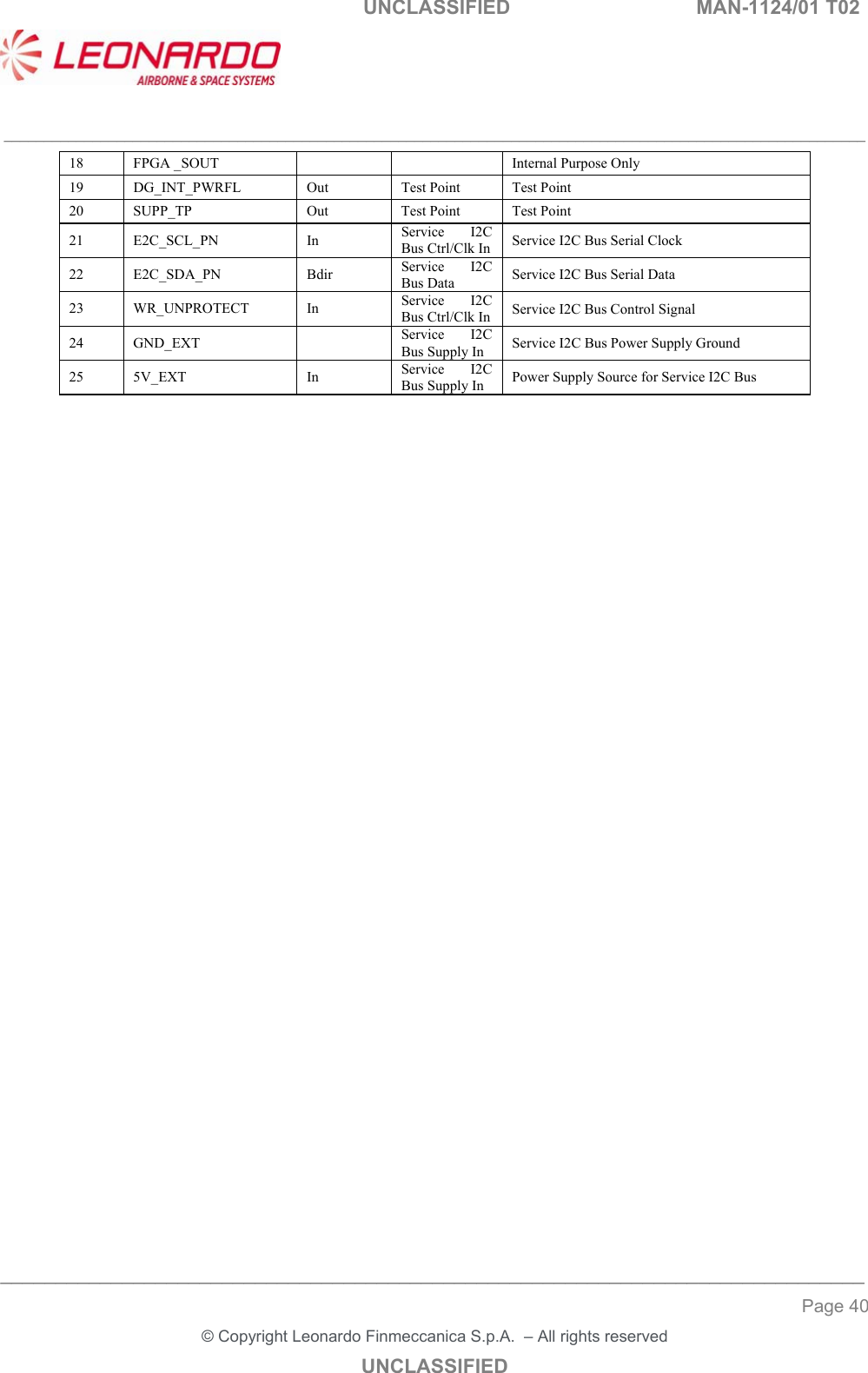
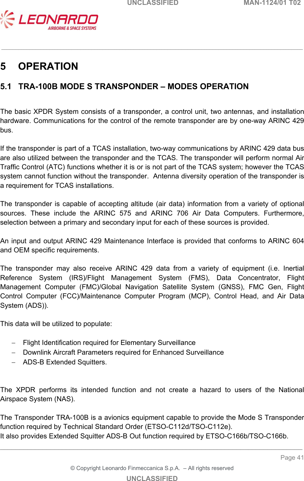
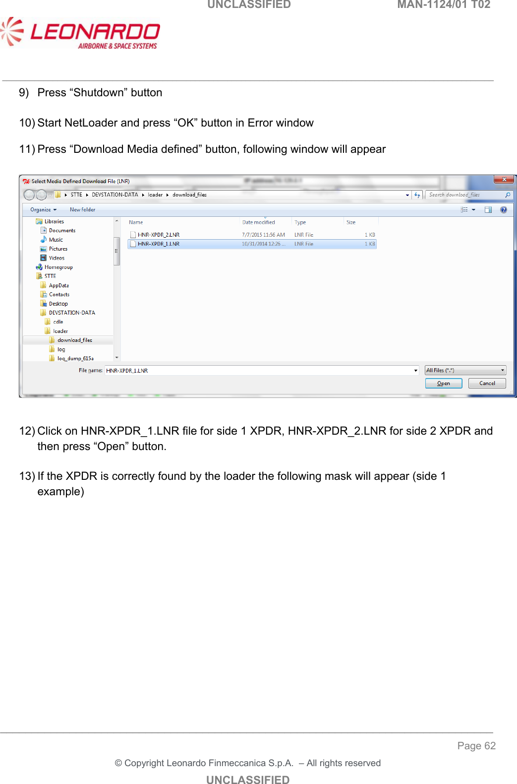
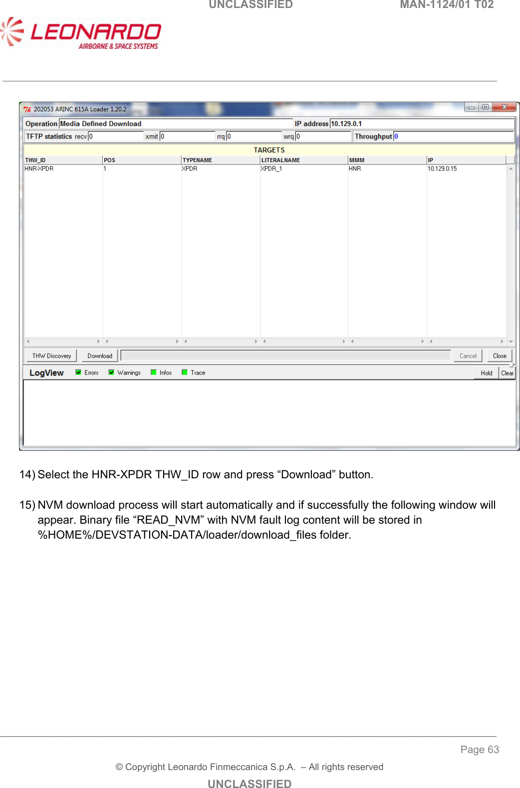
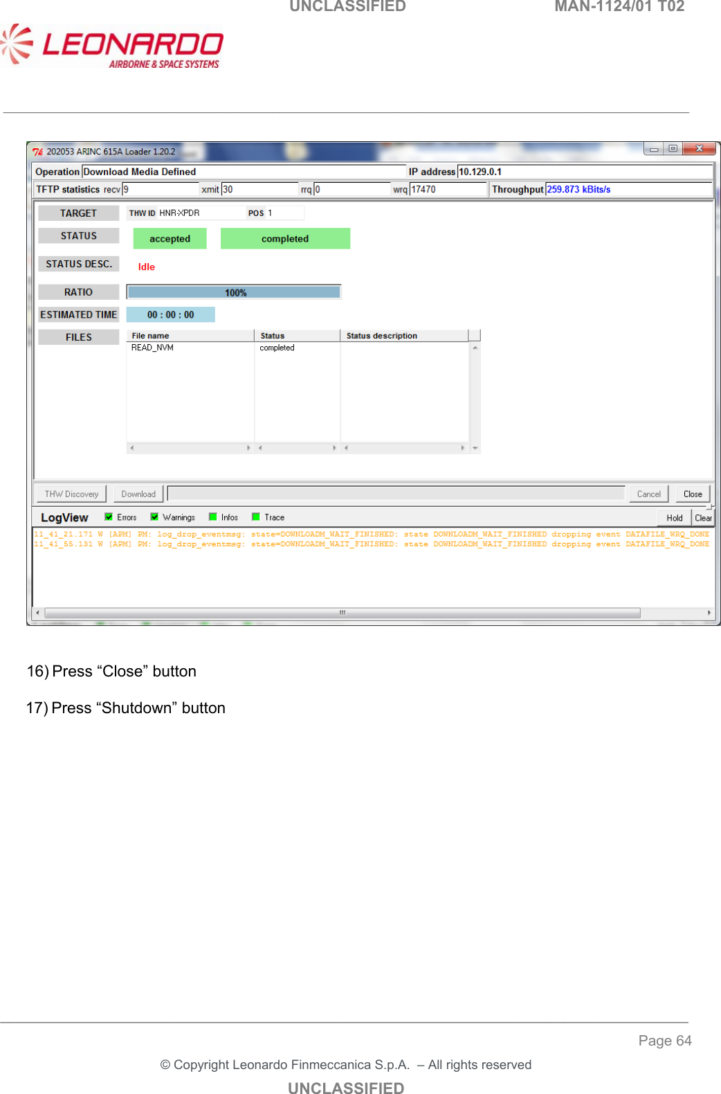
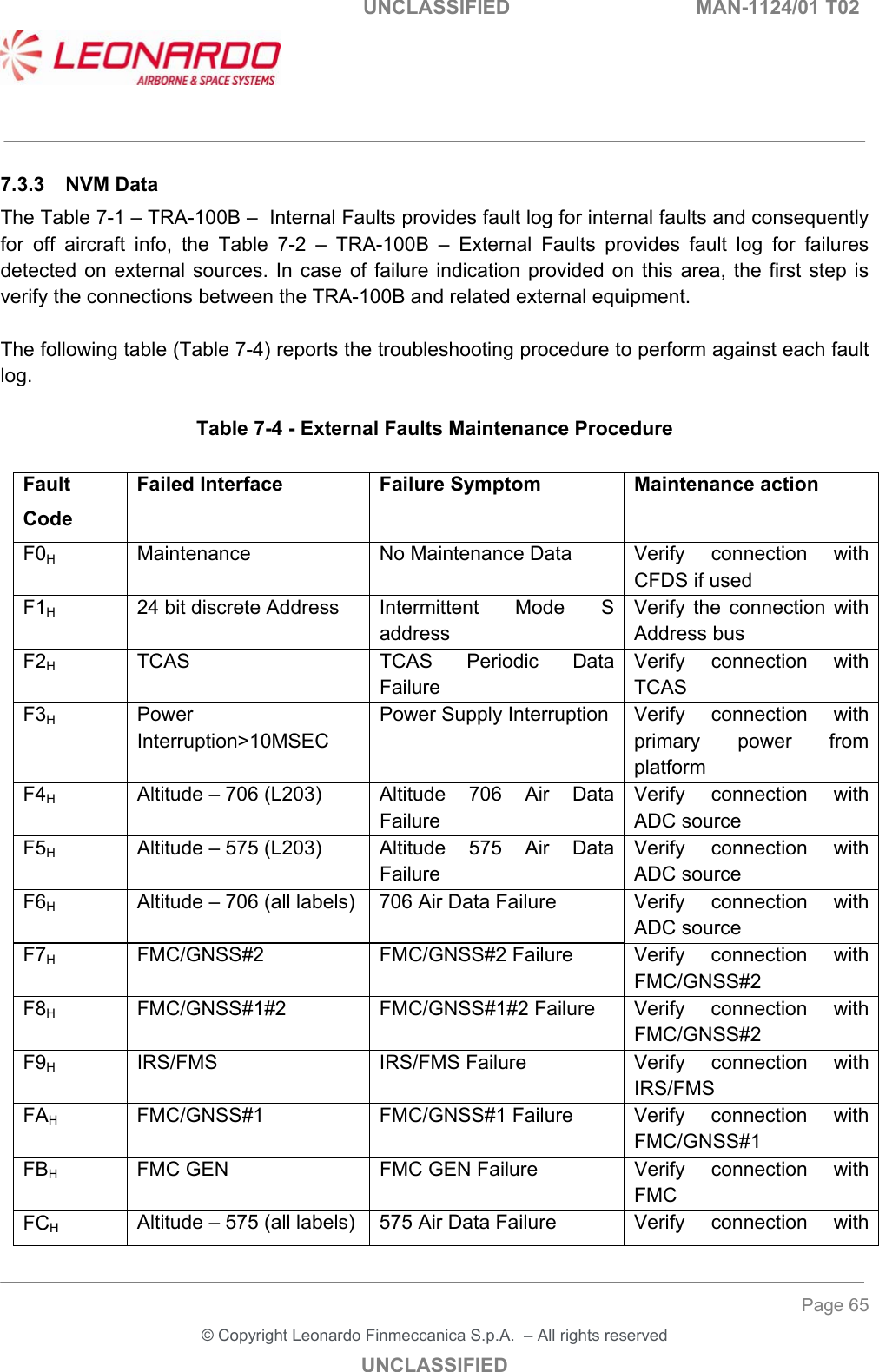
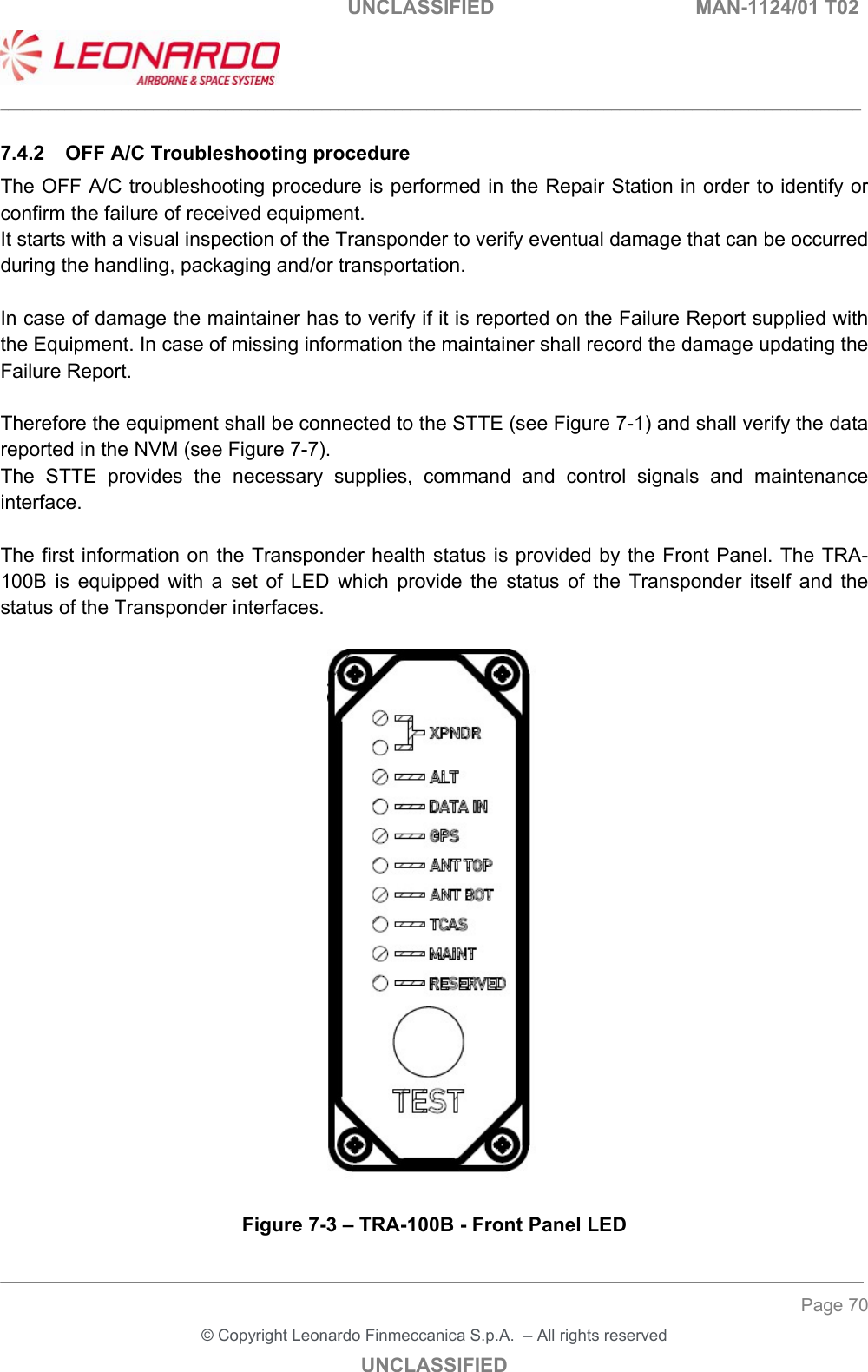
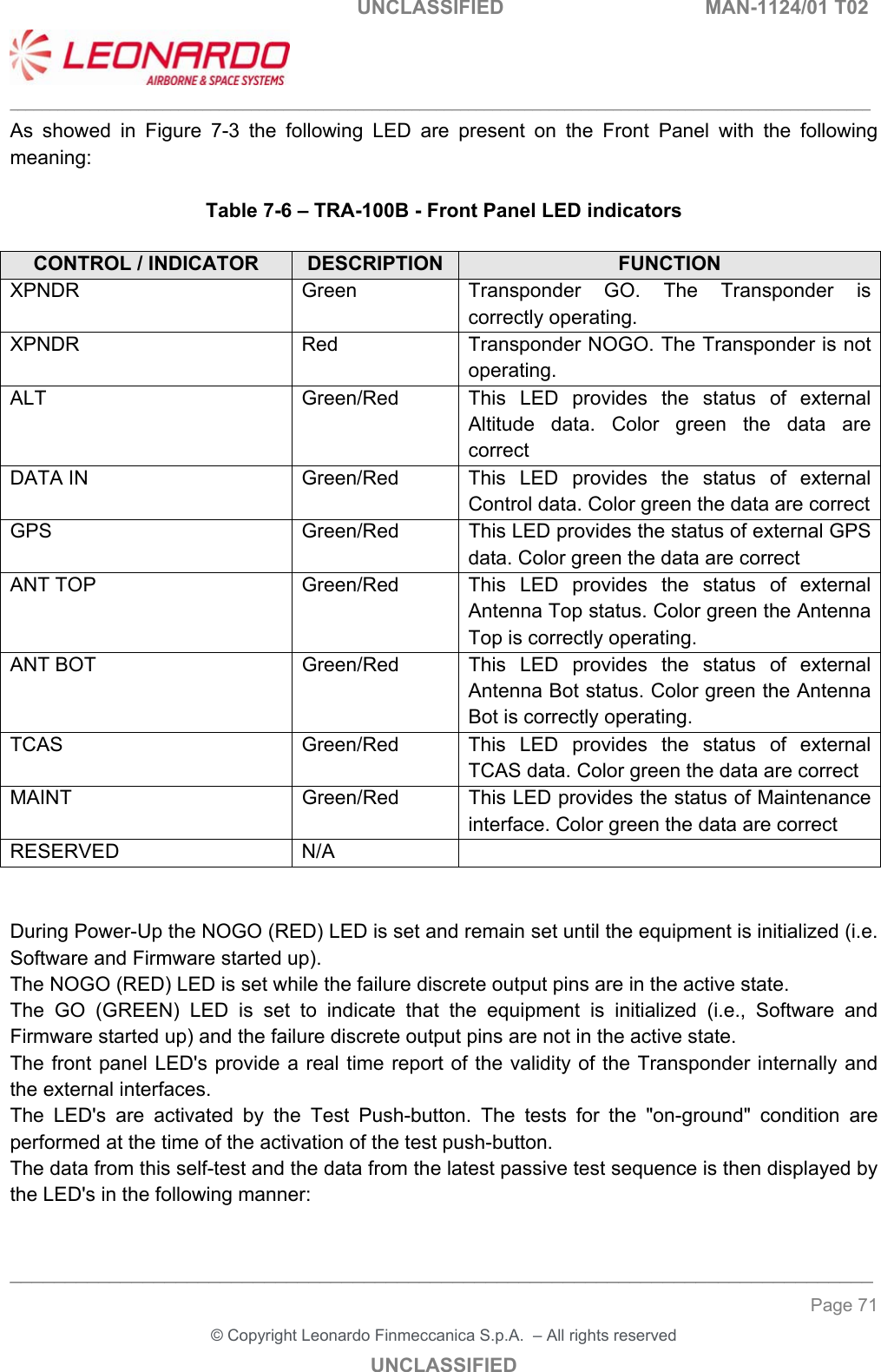
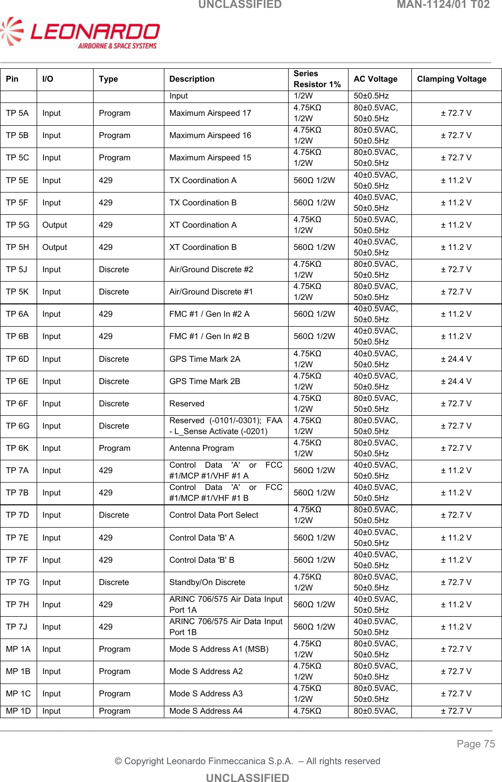
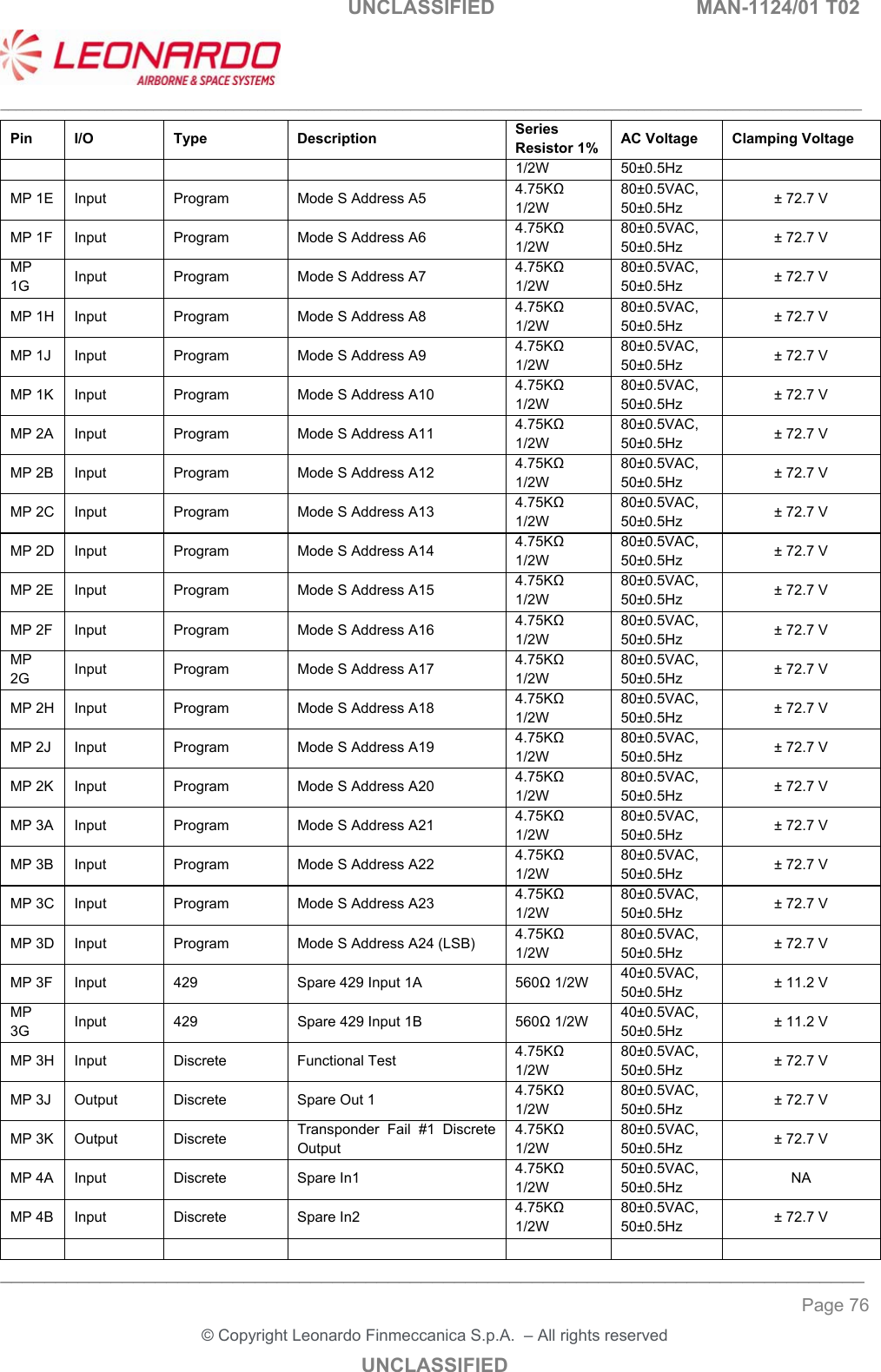
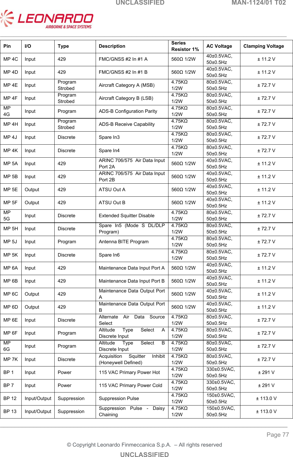
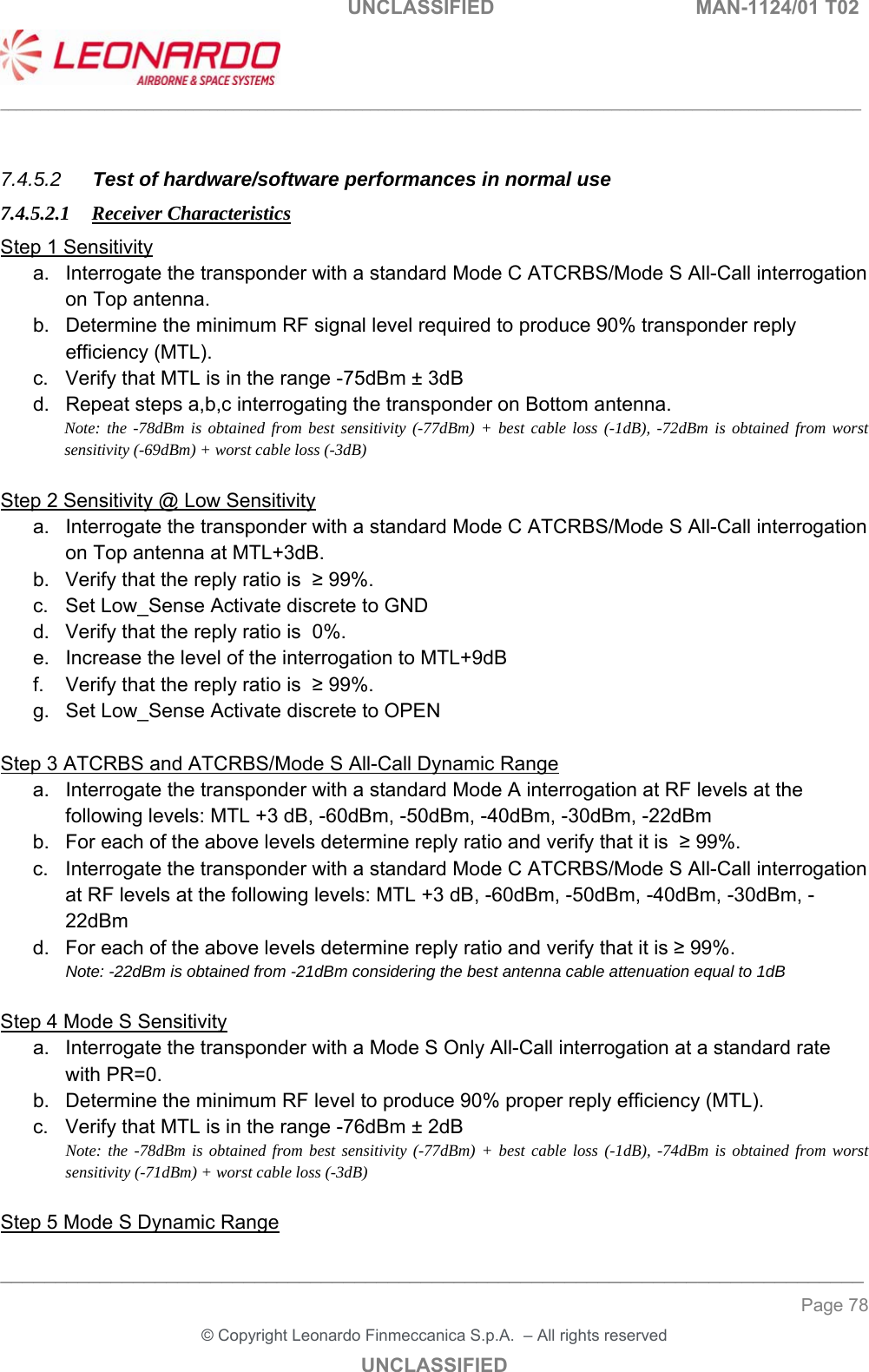
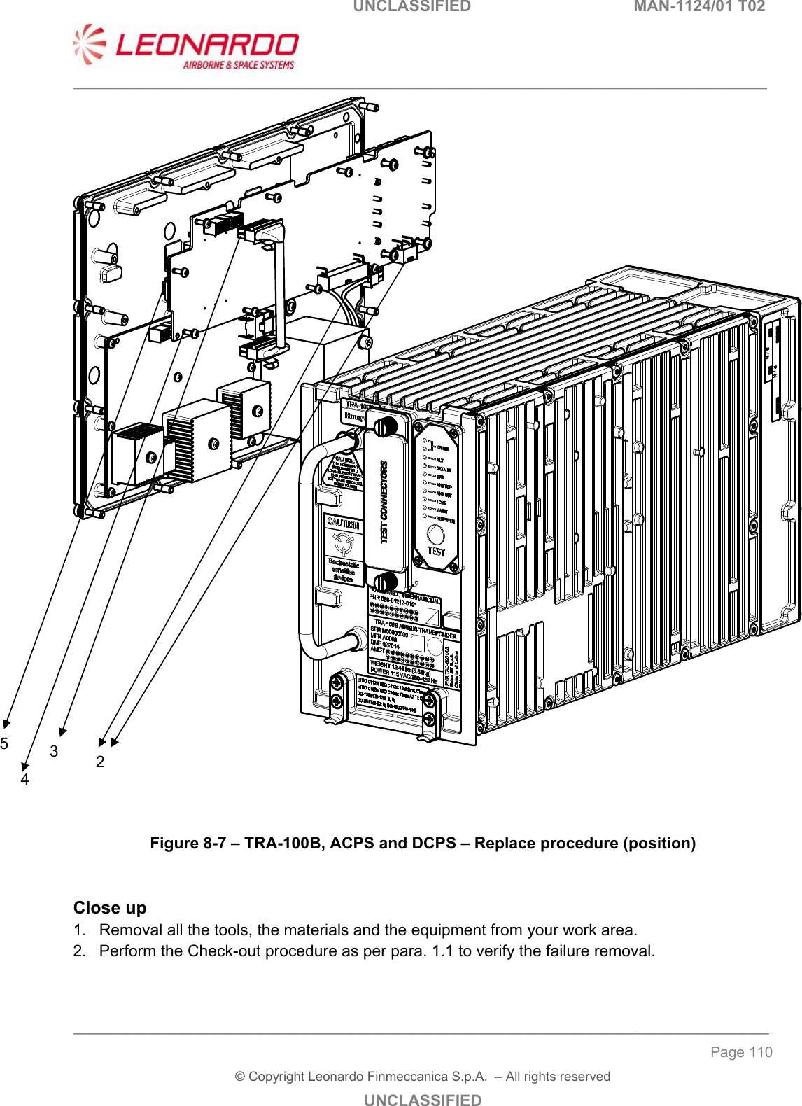
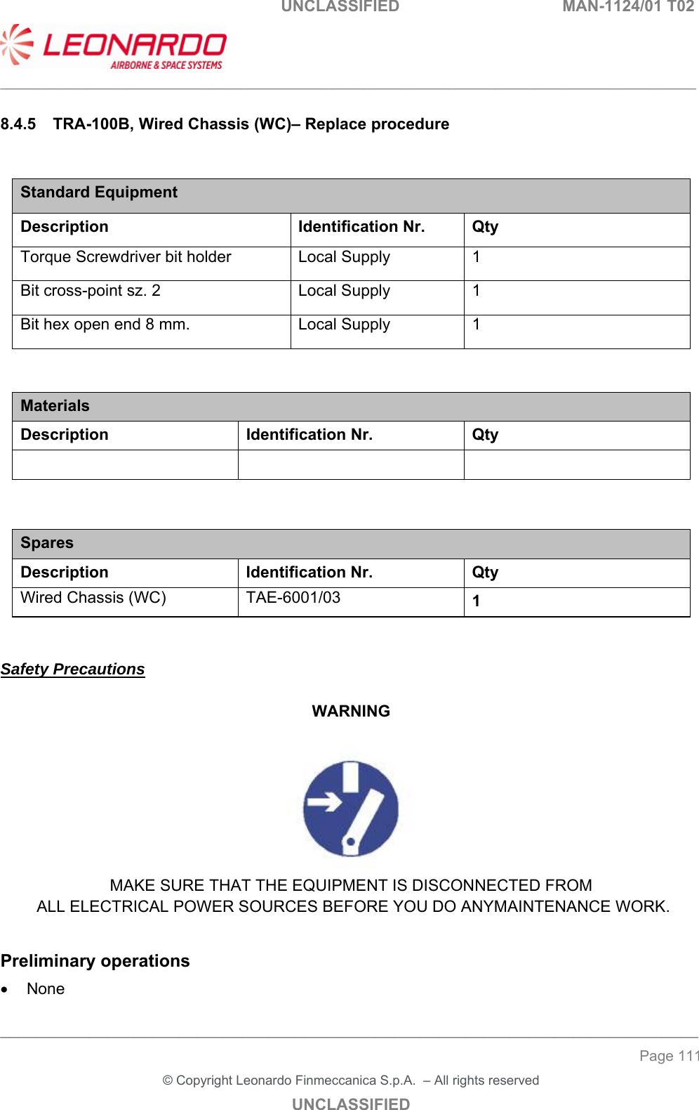
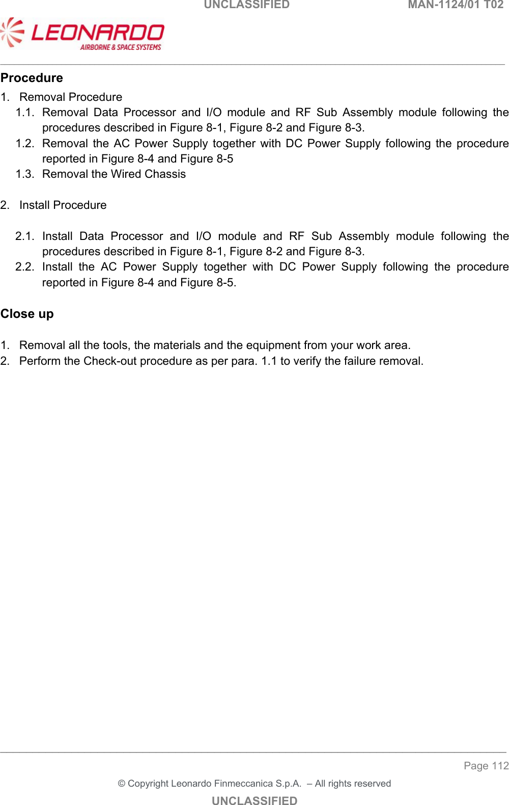
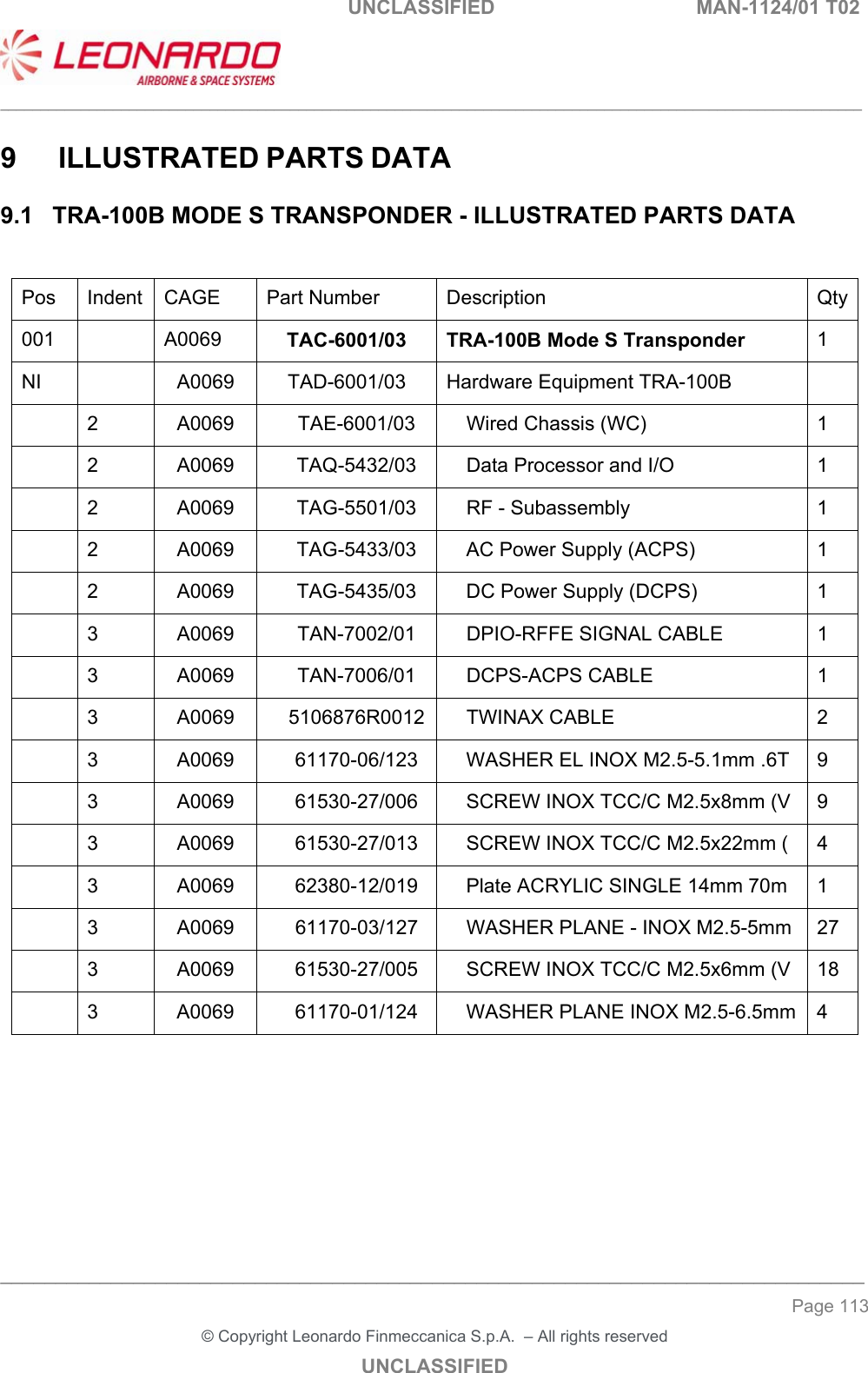
Users manual 1