LG Electronics USA LTTG94 GSM/WCDMA Telematics NAD module User Manual Installation Guide
LG Electronics USA GSM/WCDMA Telematics NAD module Users Manual Installation Guide
Contents
- 1. Users Manual
- 2. Users Manual - Installation Guide
Users Manual - Installation Guide
LG Electronics Inc. 1 13-12-16
1/12
1. Installation Guide for GEN9.4NADCANADA
This part establishes the installation guide for GEN9.4NADCANADA.
Description of installation is shown as below:
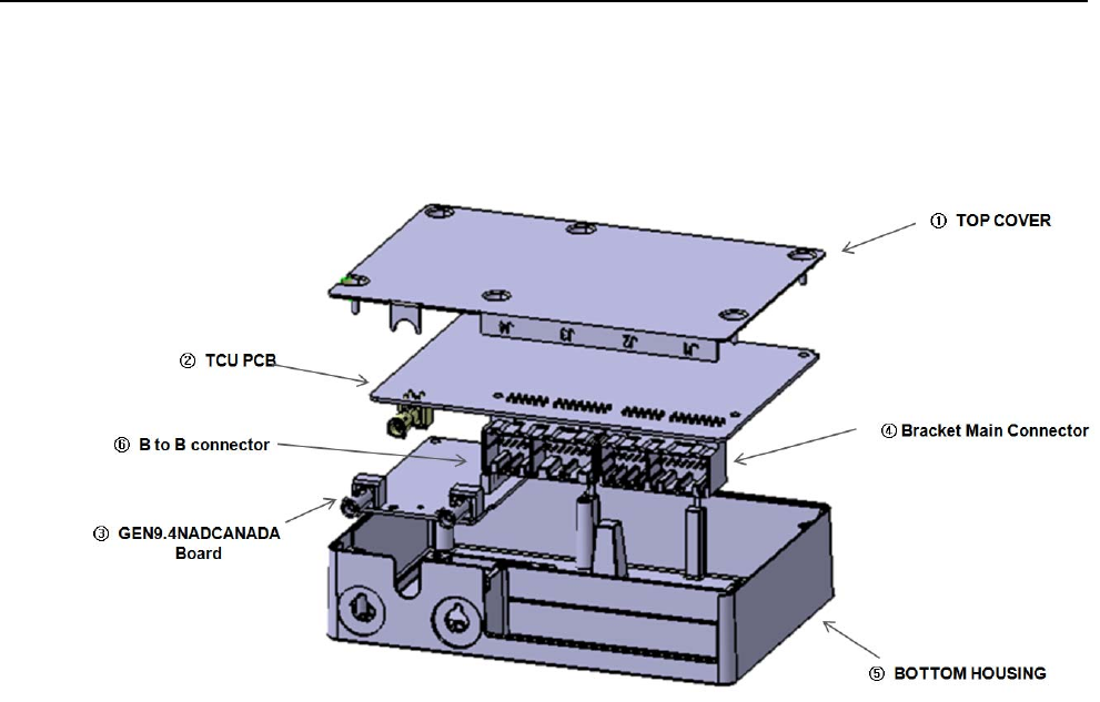
1. Number ① : Top cover
2. Number ② : TCU (Telematics Control Unit) : Power board
3. Number ③ : GEN9.4NADCANADA module
4. Number ④ : TCU main connector bracket.
5. Number ⑤ : Bottom cover
6. Number ⑥ : B to B connector
2/12
LG Electronics Inc. 2 13-12-16
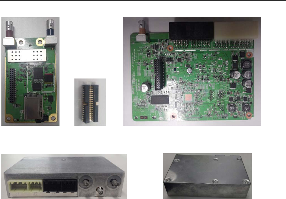
[Fig.1] VCP [module(NAD) + Power board(TCU)] setting information
[Fig.2] VCP [module(NAD) + Power board(TCU) + Housing] setting information (Full Assembly)
<Front View> <Rear View >

3/12
LG Electronics Inc. 2 13-12-16
<FCC Regulatory Notices>
1. GEN9.4NADCANADA module has been granted as limited modular approval that is limited to
that the specific host only (Telematics device). The host manufacturer is LG Electronics USA; Host
FCC ID: BEJLTTG94L.
2. GEN9.4NADCANADA module has no its power supply and it must be connected with this host
while working; and the TCU part in this host support the power.
3. A label must be affixed to the outside of the end product into which the GEN9.4NADCANADA
module is incorporated, with a statement similar to the following:
“This device contains FCC ID: BEJLTTG94.”
4. The transmitter module must not be co-located or operating in conjunction with any other
antenna or transmitter except in accordance with FCC multi-transmitter product procedures.
5. The end product with an embedded GEN9.4NADCANADA module may also need to pass the
FCC Part 15 unintentional emission testing requirements and be properly authorized per FCC Part
15.
6. This device complies with Part 15 of the FCC Rules. Operation is subject to the following two
conditions: (1) this device may not cause harmful interference, and (2) this device must accept any
interference received, including interference that may cause undesired operation.
7. Changes or modifications made to this equipment not expressly approved by LG Electronics
USA may void the FCC authorization to operate this equipment.
8. This is device is a mobile device with respect to RF exposure compliance. The antenna used for
this transmitter must be installed to provide a separation distance of at least 30 cm from all
persons. Final Installers (automobile manufacturer) must be provided with specific information
required to satisfy RF exposure compliance for installations and final host devices.
Compliance of this device in all final host configurations is the responsibility of the Grantee.
The highest permitted antenna gains including cable loss for use with this device are: GSM850/
WCDMA850: -2.4 dBi, GSM1900/WCDMA1900: -0.3 dBi.
9. The cable length that must be used in the final installation is at least 1.5 m.
- RF cable loss is proportional to the line length increases.
- RF cable type : straight FAKRA plug type RF cable.
4/12
LG Electronics Inc. 2 13-12-16
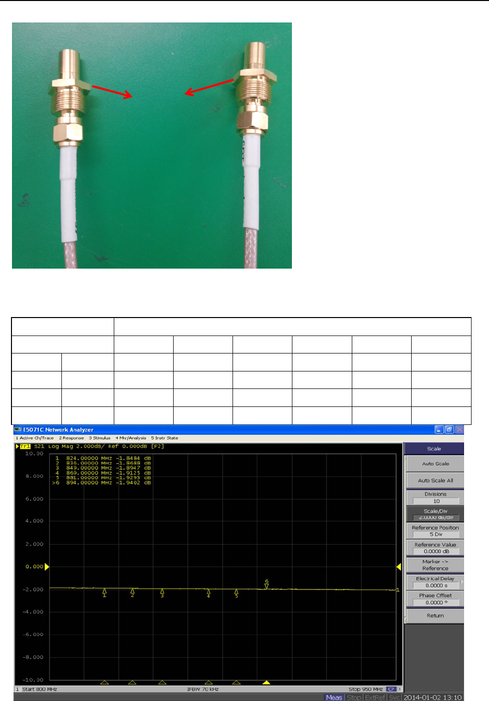
1) Low Band RF cable loss (850Mhz)
- GSM850/ WCDMA B5 (824 MHz ~ 894 MHz)
Band GSM850/ WCDMA B5
Frequency (MHz) 824 836 849 869 881 894
1.5m I.L (dB) -1.8484 -1.8688 -1.8947 -1.9125 -1.9293 -1.9402
3m I.L (dB) -3.6968 -3.7376 -3.7894 -3.825 -3.8586 -3.8804
4.5m I.L (dB) -5.5452 -5.6064 -5.6841 -5.7375 -5.7879 -5.8206
6m I.L (dB) -7.3936 -7.4752 -7.5788 -7.65 -7.7172 -7.7608
FAKRA Type
RF cable
Antenna
GEN9.4NADNA
5/12
LG Electronics Inc. 2 13-12-16
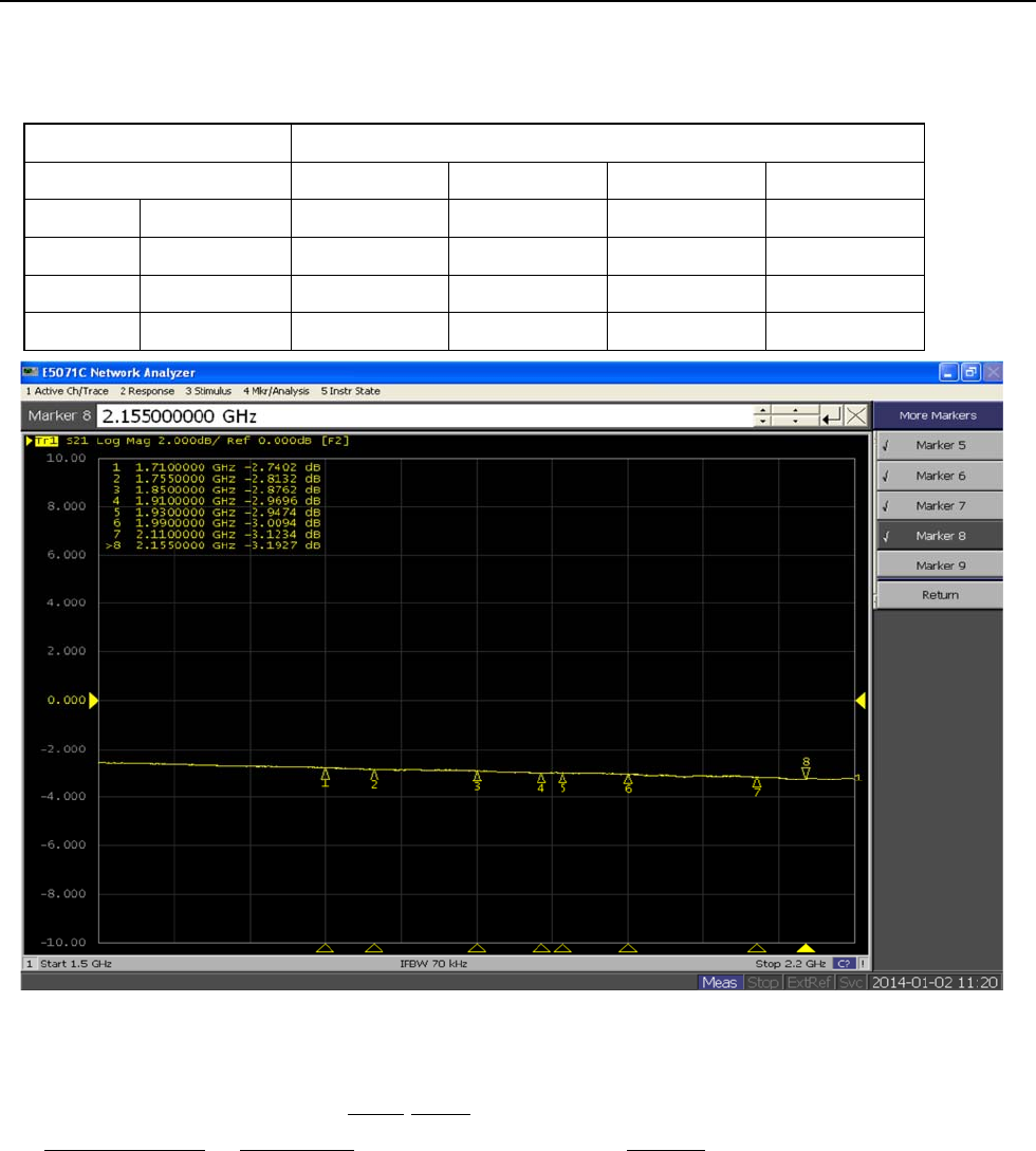
2) High Band RF cable loss
- GSM1900/ WCDMA B2 (1850MHz ~ 1990MHz)
Band GSM1900/WCDMA B2
Frequency (MHz) 1850 1910 1930 1990
1.5m I.L (dB) -2.8762 -2.9696 -2.9474 -3.0094
3m I.L (dB) -5.7524 -5.9392 -5.8948 -6.0188
4.5m I.L (dB) -8.6286 -8.9088 -8.8422 -9.0282
6m I.L (dB) -11.5048 -11.8784 -11.7896 -12.0376
* Note
I.L : insertion loss is the loss of signal power resulting from the insertion of a device in
a transmission line or optical fiber and is usually expressed in decibels(dB).