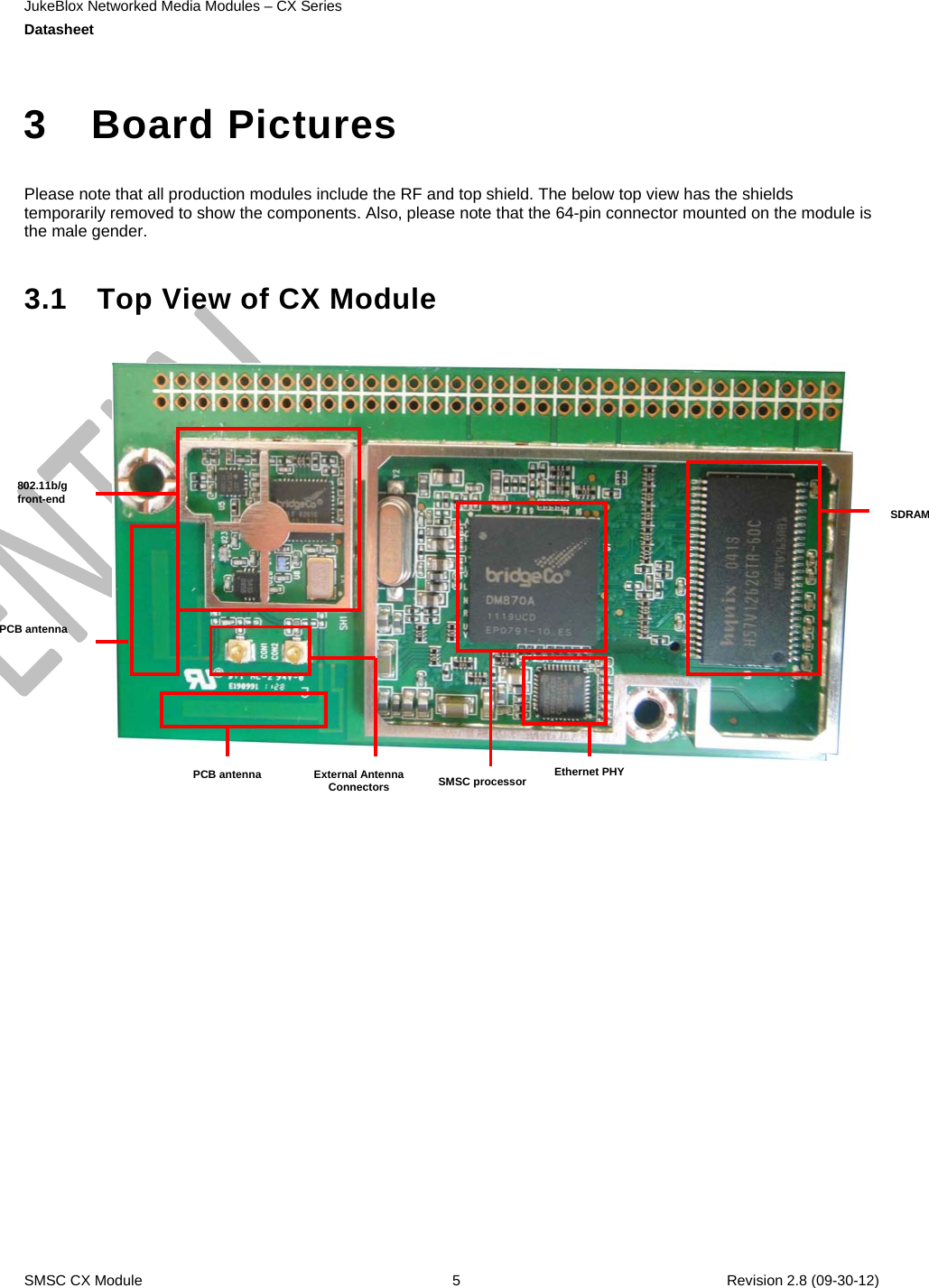
LITE ON TECHNOLOGY CX8703LB JukeBlox Networked Media Module User Manual CX870 3LB UserMan 20130115
LITE-ON Technology Corp. JukeBlox Networked Media Module CX870 3LB UserMan 20130115
Contents
- 1. (CX870-3LB) UserMan_20121218
- 2. (CX870-3LB) UserMan_20130115
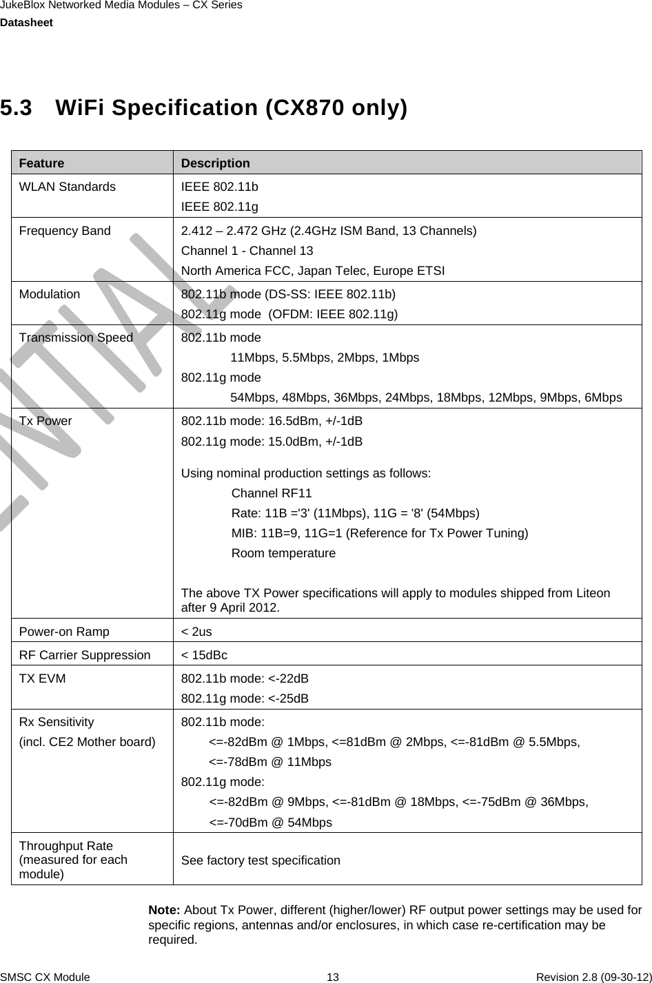
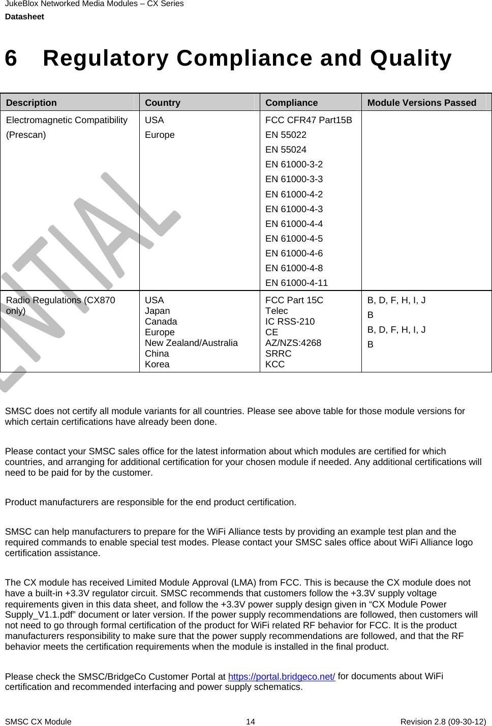
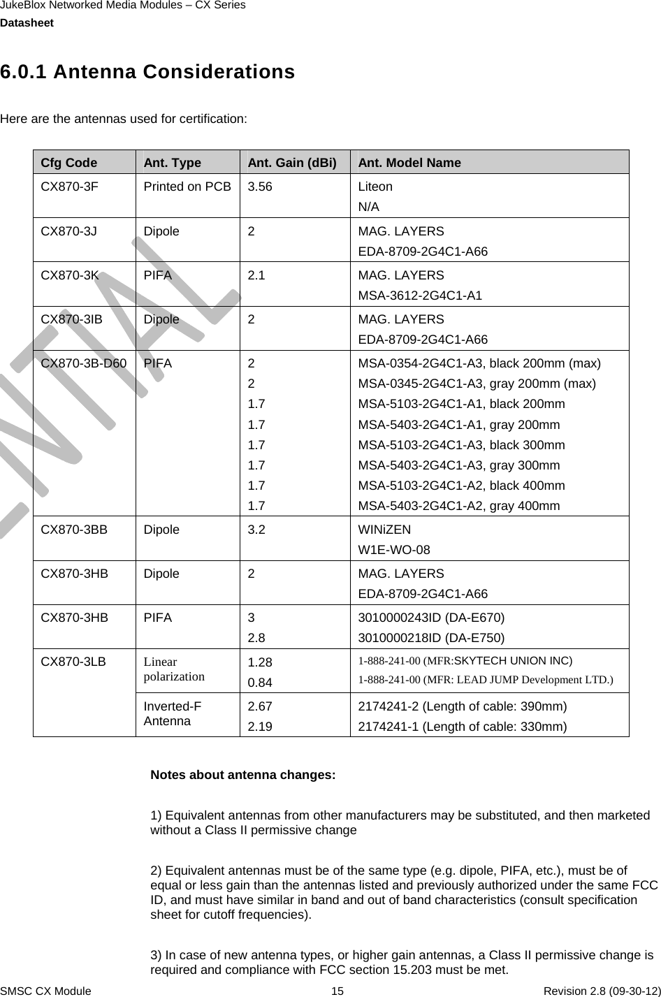
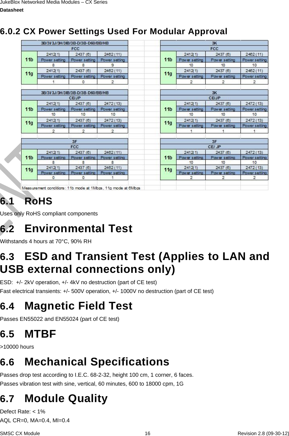
(CX870-3LB) UserMan_20130115