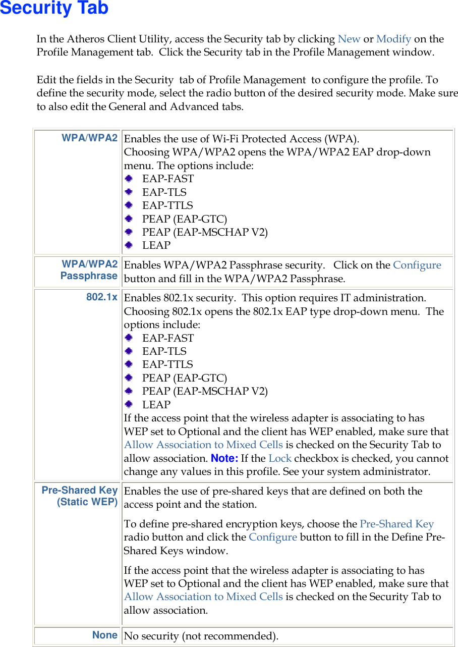
LITE ON TECHNOLOGY MP1 Low Energy Wi-Fi Single Band 802.11b/g/n Module User Manual User s Guide MP1
LITE-ON Technology Corp. Low Energy Wi-Fi Single Band 802.11b/g/n Module User s Guide MP1
UserManual.wiki
>
LITE ON TECHNOLOGY
>
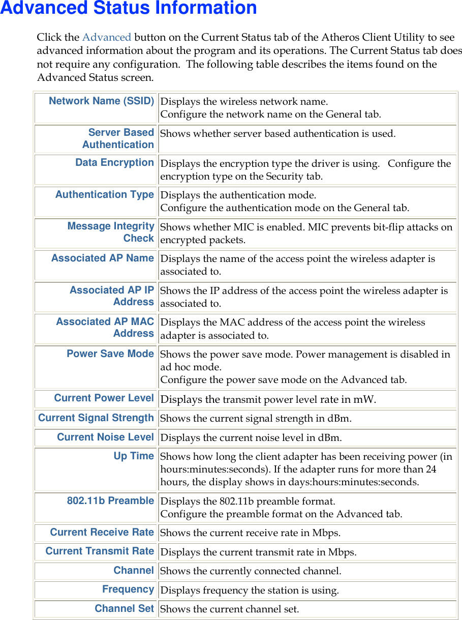
MP1 User Manual
User Manual
Navigation menu
Upload a User Manual
Namespaces
Wiki Guide
HTML
PDF
Info
Views
User Manual
Discussion / Help
Navigation
![Document Conventions Text Conventions bold Bold type within paragraph text indicates commands, file names, directory names, paths, output, or returned values. Example: The DK_Client package will not function unless you use the wdreg_install batch file. italic Within commands, italics indicate a variable that the user must specify. Example: mem_alloc size_in_bytes Titles of manuals or other published documents are also set in italics. Courier The Courier font indicates output or display. Example: Error:Unable to allocate memory for transfer! Menu The Menu character tag is used for menu items. Example: Choose Edit > Copy. [ ] Within commands, items enclosed in square brackets are optional parameters or values that the user can choose to specify or omit. { } Within commands, items enclosed in braces are options from which the user must choose. | Within commands, the vertical bar separates options. … An ellipsis indicates a repetition of the preceding parameter. > The right angle bracket separates successive menu selections. Example: Start > Programs > DK > wdreg_install.](https://usermanual.wiki/LITE-ON-TECHNOLOGY/MP1/User-Guide-2999016-Page-2.png)