Laird Connectivity 1002 SaBLE-x User Manual Rev 1
LS Research, LLC SaBLE-x Rev 1
Contents
- 1. User Manual Rev 1
- 2. User Manual Rev 2
User Manual Rev 1
SaBLE-x Module
DATASHEET
The information in this document is subject to change without notice.
330-0166 Copyright © 2015 LSR Page 1 of 14
SaBLE-xTM Bluetooth® Smart (BLE) Module
FEATURES
• Built in CC2640F128 Bluetooth
Smart (BLE 4.1) System-On-Chip
(SOC)
• 128 kB Flash / 20 kB SRAM
• RF Output Power: +5 dBm
• RF Receive Sensitivity: -96 dBm
• Size: 11.6mm x 17.9mm x 2.4mm
• Operating Voltage: 1.8V to 3.8V
• Operating Temperature: -40 to +85C
• 9.1mA Transmit Mode (+5 dBm)
• 6.1mA Receive Mode
• 1μA Standby (SRAM/CPU retention
and RTC running) with quick 100 μs
start up
• 200nA Shutdown
• 61μA/MHz Active CPU Current
• Drivers, Bluetooth Low Energy
Controller, and bootloader in ROM
• Flexible peripheral set
• On board 32 kHZ and 24 MHz
Crystals.
• Worldwide Acceptance: FCC (USA),
IC (Canada), ETSI (Europe), Giteki
(Japan), C-Tick (AU/NZ)
• REACH and RoHS compliant
APPLICATIONS
• Consumer electronics
• Mobile phone accessories
• Sports & Fitness equipment
• HID applications
• Home and Building Automation, Lighting
Control, Alarm and Security
• Electronic Shelf Labeling, Proximity
Tags
DESCRIPTION
LSR would like to announce a low-cost and low-
power consumption module which has all of the
Bluetooth Smart 4.1 functionalities.
The SaBLE-x module fully supports the single
mode Bluetooth Low Energy operation, and the
output power can support class 2. The module
provides the ability to either put your entire
application into the integrated ARM Cortex M3
microcontroller, or use the module in Network
Processor mode in conjunction with the
microcontroller of your choice. RF Core’s
dedicated ARM Cortex M0 improves system
performance and frees up FLASH memory for
custom applications.
Need to get to market quickly? Not an expert in
Bluetooth Low Energy? Need a custom
antenna? Do you need help with your host
board? LSR Design Services will be happy to
develop custom hardware or software, or help
integrate the design. Contact us at
sales@lsr.com or call us at 262-375-4400.

SaBLE-x Module
DATASHEET
The information in this document is subject to change without notice.
330-0166 Copyright © 2015 LSR Page 2 of 14
TABLE OF CONTENTS
FEATURES .......................................................................................................................... 1
APPLICATIONS ................................................................................................................... 1
DESCRIPTION ..................................................................................................................... 1
FOOTPRINT AND PIN DEFINITIONS.................................................................................. 3
PIN DESCRIPTIONS ............................................................................................................ 4
ELECTRICAL SPECIFICATIONS ........................................................................................ 5
Absolute Maximum Ratings ....................................................................................................................... 5
Recommended Operating Conditions ...................................................................................................... 5
General Characteristics .............................................................................................................................. 5
DC Characteristics ...................................................................................................................................... 6
General Power Consumption ..................................................................................................................... 7
AGENCY CERTIFICATIONS ............................................................................................... 8
AGENCY STATEMENTS ..................................................................................................... 8
Federal Communication Commission Interference Statement .............................................................. 8
Industry Canada Statements...................................................................................................................... 9
OEM RESPONSIBILITIES TO COMPLY WITH FCC AND INDUSTRY CANADA
REGULATIONS ....................................................................................................... 10
OEM LABELING REQUIREMENTS FOR END-PRODUCT .............................................. 11
OEM END PRODUCT USER MANUAL STATEMENTS.................................................... 12
EUROPE ............................................................................................................................ 13
CE Notice ................................................................................................................................................... 13
Declaration of Conformity (DOC) ............................................................................................................ 13
CONTACTING LSR............................................................................................................ 14
SaBLE-x Module
DATASHEET
The information in this document is subject to change without notice.
330-0166 Copyright © 2015 LSR Page 3 of 14
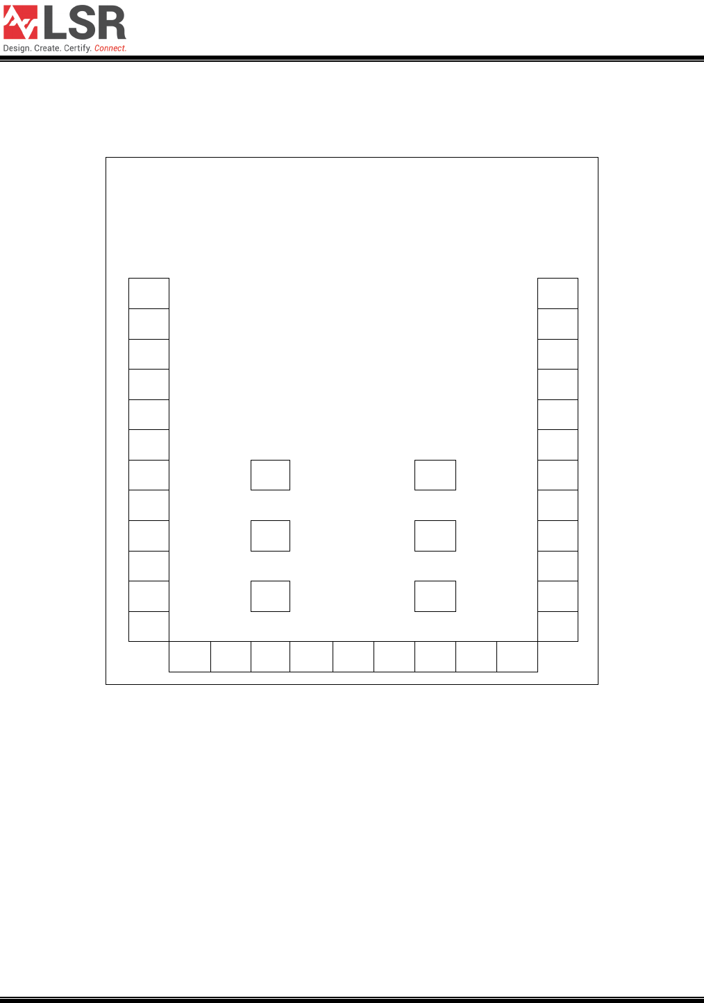
FOOTPRINT AND PIN DEFINITIONS
1 33
2 32
3 31
4 30
5 29
6 28
7 34 37 27
8 26
9 35 38 25
10 24
11 36 39 23
12 22
13 14 15 16 17 18 19 20 21
Figure 1 SaBLE-x Module Footprint (Viewed From Top)
SaBLE-x Module
DATASHEET
The information in this document is subject to change without notice.
330-0166 Copyright © 2015 LSR Page 4 of 14
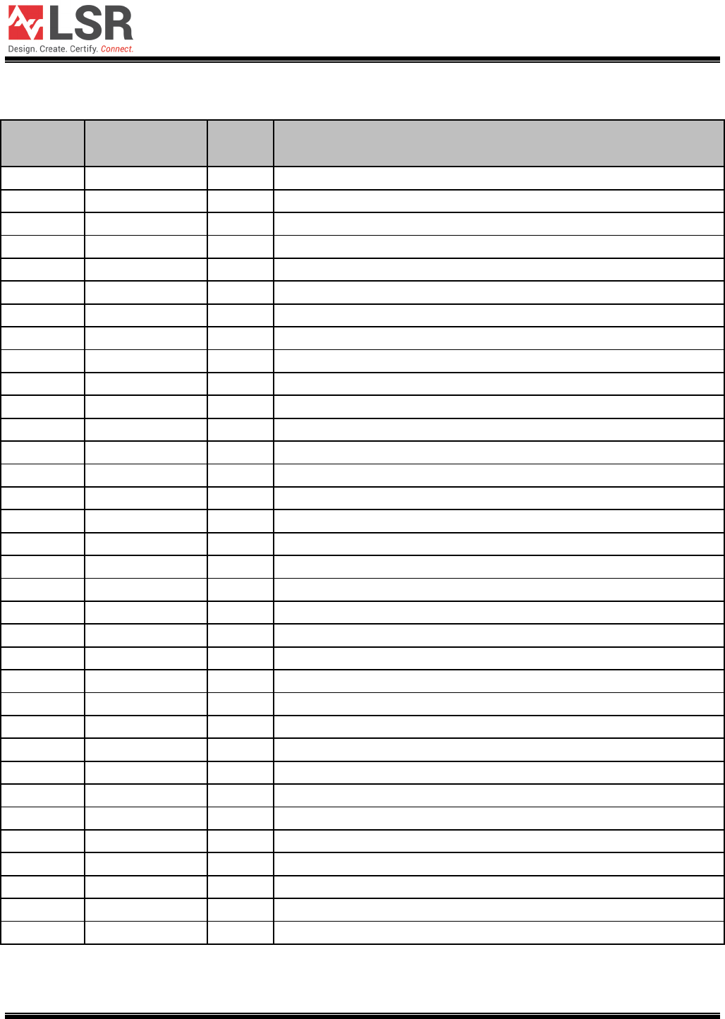
PIN DESCRIPTIONS
Module Pin Name I/O Type Description
1
RF OUT
RF
ANTENNA, 50 OHMS
2
GND
GND
GROUND
3
GND
GND
GROUND
4
NC
-
NO CONNECT (DO NOT CONNECT)
5
NC
-
NO CONNECT (DO NOT CONNECT)
6
/RESET
DI
ACTIVE LOW RESET. 100kΩ PULL-UP
7
JTAG TCKC
DI/DIO
JTAG TCKC
8
JTAG TMSC
DIO
JTAG TMSC
9
NC
-
NO CONNECT (DO NOT CONNECT)
10
NC
-
NO CONNECT (DO NOT CONNECT)
11
VCC
PI
POWER SUPPLY TO MODULE
12
VCC
PI
POWER SUPPLY TO MODULE
13
DIO 5/JTAG TDO
DIO
GPIO, JTAG TDO, ULP SENSOR INTERFACE, LED DRIVING CAPABILITY
14
DIO 6/JTAG TDI
DIO
GPIO, JTAG TDI, ULP SENSOR INTERFACE, LED DRIVING CAPABILITY
15
DIO 4
DIO
GPIO, LED DRIVING CAPABILITY
16
DIO 3
DIO
GPIO, LED DRIVING CAPABILITY
17
DIO 2
DIO
GPIO, ULP SENSOR INTERFACE, LED DRIVING CAPABILITY
18
DIO 1/BOOT RX
DIO
GPIO, ULP SENSOR INTERFACE, BOOTLOADER RX (UART0)
19
DIO 0/BOOT TX
DIO
GPIO, ULP SENSOR INTERFACE, BOOTLOADER TX (UART0)
20
DIO 7
DIO
GPIO, ANALOG INPUT, ULP SENSOR INTERFACE
21
DIO 8
DIO
GPIO, ANALOG INPUT, ULP SENSOR INTERFACE
22
GND
GND
GROUND
23
DIO 10
DIO
GPIO, ANALOG INPUT, ULP SENSOR INTERFACE
24
DIO 9
DIO
GPIO, ANALOG INPUT, ULP SENSOR INTERFACE
25
NC
-
NO CONNECT (DO NOT CONNECT)
26
NC
-
NO CONNECT (DO NOT CONNECT)
27
NC
-
NO CONNECT (DO NOT CONNECT)
28
NC
-
NO CONNECT (DO NOT CONNECT)
29
DIO 11
DIO
GPIO, ANALOG INPUT, ULP SENSOR INTERFACE
30
DIO 12
DIO
GPIO, ANALOG INPUT, ULP SENSOR INTERFACE
31
DIO 13
DIO
GPIO, ANALOG INPUT, ULP SENSOR INTERFACE
32
DIO 14
DIO
GPIO, ANALOG INPUT, ULP SENSOR INTERFACE
33
GND
GND
GROUND
34-39
GND
GND
GROUND AND THERMAL RELIEF PADS
PI = Power Input GND = Ground DI = Digital Input DO = Digital Output DIO = Digital Input/Output AI = Analog Input
RF = Bi-directional RF Port Note: See the Texas Instruments CC2640 datasheet and user guide for further details on the I/O.
Table 1 SaBLE-x Pin Descriptions
SaBLE-x Module
DATASHEET
The information in this document is subject to change without notice.
330-0166 Copyright © 2015 LSR Page 5 of 14
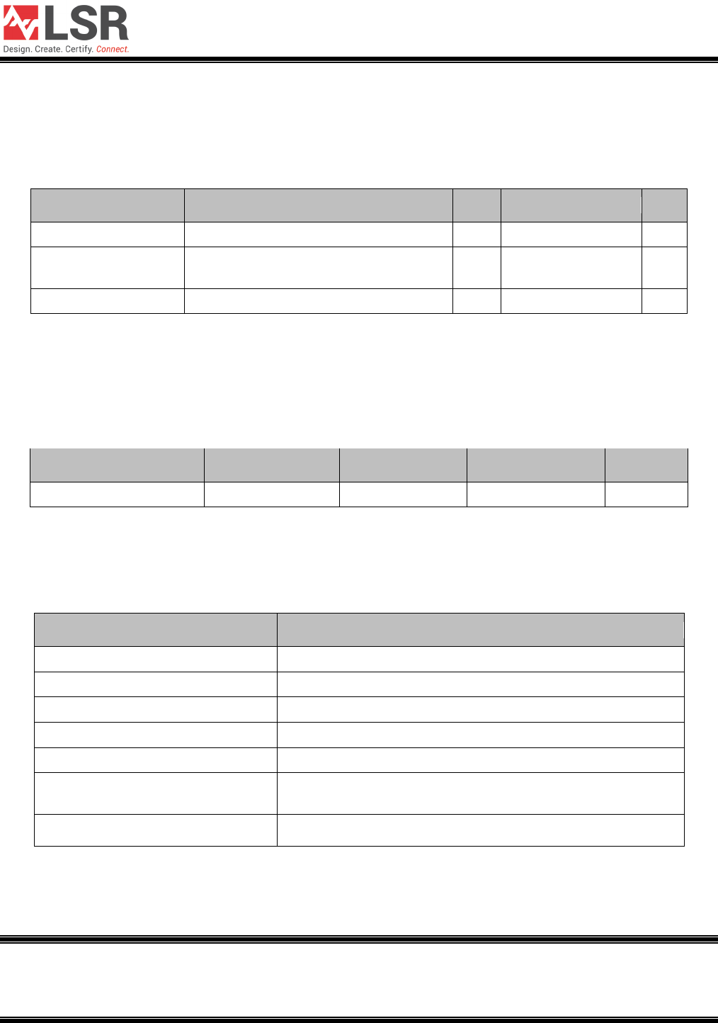
ELECTRICAL SPECIFICATIONS
Absolute Maximum Ratings
Symbol
Description
Min
Max
Unit
VCC
Digital Input Supply Voltage
-0.3
4.1
V
Voltage on any digital
pin
-0.3 VCC+0.3, max 4.1 V
Input RF level
+5
dBm
Table 2 Absolute Maximum Ratings1
Recommended Operating Conditions
Test conditions: Ambient Temp = 25°C
Symbol
Min
Typ
Max
Unit
VCC
1.8
3.3
3.8
V
Table 3 Recommended Operating Conditions
General Characteristics
Characteristic
Description
Model Name
SaBLE-x
Product Description
Bluetooth Low Energy Wireless Module
Dimension
11.63 mm x 17.86 mm x 2.4 mm (W*L*T)
Operating temperature
-40°C to 85°C
Storage temperature
-40°C to 85°C
Humidity
Operating Humidity 10% to 95% Non-Condensing
Storage Humidity 5% to 95% Non-Condensing
Weight 0.75g +/- 0.05g
Table 4 General Characteristics
1 Under no circumstances should exceeding the ratings specified in the Absolute Maximum Ratings section be
allowed. Stressing the module beyond these limits may result permanent damage to the module that is not
covered by the warranty.
SaBLE-x Module
DATASHEET
The information in this document is subject to change without notice.
330-0166 Copyright © 2015 LSR Page 6 of 14
DC Characteristics
Parameter
Test Conditions
Min
Typ
Max
Unit
Input low-to-high transition with
hysteresis
Transition from 01, TA= 25C, VCC=1.8V 1.07 V
Input high-to-low transition with
hysteresis
Transition from 10, TA= 25C, VCC=1.8V .74 V
Input hysteresis
Difference between 01 and 10.
.33
V
Input low-to-high transition with
hysteresis
Transition from 01, TA= 25C, VCC=3.8V 1.94 V
Input high-to-low transition with
hysteresis
Transition from 10, TA= 25C, VCC=3.8V 1.54 V
Input hysteresis
Difference between 01 and 10.
.4
V
Logic-0 output voltage, 4 mA pins
Output load 4 mA, TA= 25C, VCC=1.8V
.26
V
Logic-1 output voltage, 4 mA pins
Output load 4 mA, TA= 25C, VCC=1.8V
1.54
V
Logic-0 output voltage, 8 mA pins
Output load 8 mA, TA= 25C, VCC=1.8V
.21
V
Logic-1 output voltage, 8 mA pins
Output load 8 mA, TA= 25C, VCC=1.8V
1.58
V
Logic-0 output voltage, 4 mA pins
Output load 4 mA, TA= 25C, VCC=3.0V
.33
V
Logic-1 output voltage, 4 mA pins
Output load 4 mA, TA= 25C, VCC=3.0V
2.72
V
Logic-0 output voltage, 8 mA pins
Output load 8 mA, TA= 25C, VCC=3.0V
.28
V
Logic-1 output voltage, 8 mA pins
Output load 8 mA, TA= 25C, VCC=3.0V
2.68
V
Input pullup current
Vpad=0V, TA= 25C, VCC=1.8V
72
uA
Input pulldown current
Vpad=1.8V, TA= 25C, VCC=1.8V
22
uA
Input pullup current
Vpad=0V, TA= 25C, VCC=3.8V
277
uA
Input pulldown current
Vpad=3.8V, TA= 25C, VCC=3.8V
113
uA
Table 5 SaBLE-x Module Bluetooth General DC Characteristics
SaBLE-x Module
DATASHEET
The information in this document is subject to change without notice.
330-0166 Copyright © 2015 LSR Page 7 of 14
General Power Consumption
TA = 25°C and VCC = 3 V
Parameter
Test Conditions
Min
Typ
Max
Unit
Shutdown
No clocks running, no data retention
200
nA
Standby 1
With RTC, CPU, RAM and partial register retention.
XOSC_LF
1.2 uA
Standby 2
With Cache, RTC, CPU, RAM and partial register
retention. XOSC_LF
2.7 uA
Idle
Supply Systems and RAM powered.
550
uA
Active Core running CoreMark
1.45mA +
31uA/MHz
Radio Receive
6.1
mA
Radio Transmit
+5 dBm output power
9.1
mA
Table 6 SaBLE-x Module Bluetooth Power Consumption Specifications
SaBLE-x Module
DATASHEET
The information in this document is subject to change without notice.
330-0166 Copyright © 2015 LSR Page 8 of 14
AGENCY CERTIFICATIONS
FCC ID: TFB-1002, 15.247
IC ID: 5969A-1002, RSS 210
CE: Compliant to standards EN 60950-1, EN 300 328, and EN 301 489
AGENCY STATEMENTS
Federal Communication Commission Interference Statement
This equipment has been tested and found to comply with the limits for a Class B digital device,
pursuant to Part 15 of the FCC Rules. These limits are designed to provide reasonable protection
against harmful interference in a residential installation. This equipment generates uses and can radiate
radio frequency energy and, if not installed and used in accordance with the instructions, may cause
harmful interference to radio communications. However, there is no guarantee that interference will not
occur in a particular installation. If this equipment does cause harmful interference to radio or television
reception, which can be determined by turning the equipment off and on, the user is encouraged to try
to correct the interference by one of the following measures:
• Reorient or relocate the receiving antenna.
• Increase the separation between the equipment and receiver.
• Connect the equipment into an outlet on a circuit different from that to which the receiver is
connected.
• Consult the dealer or an experienced radio/TV technician for help.
This device complies with Part 15 of the FCC Rules. Operation is subject to the following two
conditions: (1) This device may not cause harmful interference, and (2) this device must accept any
interference received, including interference that may cause undesired operation.
This portable transmitter with its antenna complies with FCC/IC RF exposure limits for general
population / uncontrolled exposure.
FCC CAUTION: Any changes or modifications not expressly approved by the party
responsible for compliance could void the user's authority to operate this equipment.

SaBLE-x Module
DATASHEET
The information in this document is subject to change without notice.
330-0166 Copyright © 2015 LSR Page 9 of 14
Industry Canada Statements
This device complies with Industry Canada License-exempt RSS standard(s). Operation is subject to
the following two conditions: (1) this device may not cause interference, and (2) this device must accept
any interference, including interference that may cause undesired operation of the device.
To reduce potential radio interference to other users, the antenna type and its gain should be so
chosen that the equivalent isotropically radiated power (e.i.r.p.) is not more than that permitted for
successful communication.
This device has been designed to operate with the antenna(s) listed below, and having a maximum
gain of 0 dBi (PCB Trace), 2.0 dBi (LSR 2.4 GHz Dipole), 2.0 dBi (LSR 2.4 GHz FlexPIFA), and 2.0
(LSR 2.4 GHz FlexNotch). Antennas not included in this list or having a gain greater than 0 dB, 2.0 dBi,
2.0 dBi, and 2.0 dBi are strictly prohibited for use with this device. The required antenna impedance is
50 ohms.
List of all Antennas Acceptable for use with the Transmitter
1) On module PCB trace antenna.
2) LSR 001-0001 center-fed 2.4 GHz dipole antenna and LSR 080-0001 U.FL to Reverse Polarity SMA
connector cable.
3) LSR 001-0014 2.4 GHz FlexPIFA antenna.
4) LSR 001-0015 2.4 GHz FlexNotch antenna.
Cet appareil est conforme aux normes d'Industrie Canada exempts de licence RSS (s). L'opération
est soumise aux deux conditions suivantes: (1) cet appareil ne peut pas provoquer d'interférences
et (2) cet appareil doit accepter toute interférence, y compris les interférences qui peuvent causer un
mauvais fonctionnement de l'appareil.
Pour réduire le risque d'interférence aux autres utilisateurs, le type d'antenne et son gain doiventêtre
choisis de manière que la puissance isotrope rayonnée équivalente (PIRE) ne dépasse pascelle
permise pour une communication réussie.
Cet appareil a été conçu pour fonctionner avec l'antenne (s) ci-dessous, et ayant un gain maximum de
0 dBi (PCB Trace), 2,0 dBi (LSR 2.4 GHz Dipole), 2,0 dBi (LSR 2.4 GHz FlexPIFA), et 2,0 dBi (LSR 2.4
GHz FlexNotch). Antennes pas inclus dans cette liste ou présentant un gain supérieur à 0 dB, 2,0 dBi,
2,0 dBi, et 2,0 dBi sont strictement interdites pour une utilisation avec cet appareil. L'impédance
d'antenne requise est de 50 ohms.
Liste de toutes les antennes acceptables pour une utilisation avec l'émetteur
1) Le module d'antenne PCB trace.
2) LSR 001-0001 centre-fed 2,4 GHz antenne dipôle et LSR 080-0001 U.FL pour inverser câble
connecteur SMA à polarité.
3) LSR 001-0014 antenne FlexPIFA 2,4 GHz.
4) LSR 001-0015 antenne FlexNotch 2,4 GHz.
SaBLE-x Module
DATASHEET
The information in this document is subject to change without notice.
330-0166 Copyright © 2015 LSR Page 10 of 14
OEM RESPONSIBILITIES TO COMPLY WITH FCC AND INDUSTRY CANADA
REGULATIONS
The SaBLE-xModule has been certified for integration into products only by OEM integrators under the
following conditions:
The antennas for this transmitter must not be co-located with any other transmitters except in
accordance with FCC and Industry Canada multi-transmitter procedures. Co-location means having a
separation distance of less than 20 cm between transmitting antennas.
As long as the two conditions above are met, further transmitter testing will not be required.
However, the OEM integrator is still responsible for testing their end-product for any additional
compliance requirements required with this module installed (for example, digital device
emissions, PC peripheral requirements, etc.).
IMPORTANT NOTE: In the event that these conditions cannot be met (for certain
configurations or co-location with another transmitter), then the FCC and Industry
Canada authorizations are no longer considered valid and the FCC ID and IC Certification
Number cannot be used on the final product. In these circumstances, the OEM integrator
will be responsible for re-evaluating the end product (including the transmitter) and
obtaining a separate FCC and Industry Canada authorization.
Le module de SaBLE-xa été certifié pour l'intégration dans des produits uniquement par des
intégrateurs OEM dans les conditions suivantes:
Les antennes pour ce transmetteur ne doit pas être co-localisés avec les autres émetteurs sauf en
conformité avec la FCC et Industrie Canada multi-émetteur procédures. Co-localisation des moyens
ayant une distance de séparation inférieure à 20 cm entre les antennes d'émission.
Tant que les deux conditions précitées sont réunies, les tests de transmetteurs supplémentaires ne
seront pas tenus. Toutefois, l'intégrateur OEM est toujours responsable de tester leur produit final pour
toutes les exigences de conformité supplémentaires requis avec ce module installé (par exemple, les
émissions appareil numérique, les exigences de périphériques PC, etc.)
NOTE IMPORTANTE: Dans le cas où ces conditions ne peuvent être satisfaites (pour
certaines configurations ou de co-implantation avec un autre émetteur), puis la FCC et
Industrie autorisations Canada ne sont plus considérés comme valides et l'ID de la FCC
et IC numéro de certification ne peut pas être utilisé sur la produit final. Dans ces
circonstances, l'intégrateur OEM sera chargé de réévaluer le produit final (y compris
l'émetteur) et l'obtention d'un distincte de la FCC et Industrie Canada l'autorisation.

SaBLE-x Module
DATASHEET
The information in this document is subject to change without notice.
330-0166 Copyright © 2015 LSR Page 11 of 14
OEM LABELING REQUIREMENTS FOR END-PRODUCT
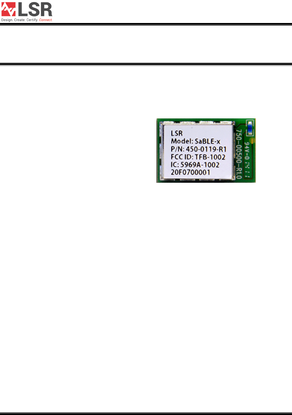
The SaBLE-x module is labeled with its own FCC ID and IC Certification Number. The FCC ID and IC
certification numbers are not visible when the module is installed inside another device, as such the
end device into which the module is installed must display a label referring to the enclosed module.
The final end product must be labeled in a visible area with the following:
“Contains Transmitter Module FCC ID: TFB-1002”
“Contains Transmitter Module IC: 5969A-1002”
or
“Contains FCC ID: TFB-1002”
“Contains IC: 5969A-1002”
The OEM of the SaBLE-x module must only use the approved antenna(s) listed above, which have
been certified with this module.
Le module de SaBLE-x est étiqueté avec son propre ID de la FCC et IC numéro de certification. L'ID de
la FCC et IC numéros de certification ne sont pas visibles lorsque le module est installé à
l'intérieur d'un autre appareil, comme par exemple le terminal dans lequel le module est installé
doit afficher une etiquette faisant référence au module ci-joint. Le produit final doit être étiqueté dans un
endroit visible par le suivant:
“Contient Module émetteur FCC ID: TFB-1002"
“Contient Module émetteur IC: 5969A-1002"
ou
“Contient FCC ID: TFB-1002"
“Contient IC: 5969A-1002"
Les OEM du module SaBLE-x ne doit utiliser l'antenne approuvée (s) ci-dessus, qui ont été
certifiés avec ce module.
SaBLE-x Module
DATASHEET
The information in this document is subject to change without notice.
330-0166 Copyright © 2015 LSR Page 12 of 14
OEM END PRODUCT USER MANUAL STATEMENTS
The OEM integrator should not provide information to the end user regarding how to install or remove
this RF module or change RF related parameters in the user manual of the end product.
Other user manual statements may apply.
L'intégrateur OEM ne devraient pas fournir des informations à l'utilisateur final sur la façon d'installer ou
de supprimer ce module RF ou modifier les paramètres liés RF dans le manuel utilisateur du produit
final.
Autres déclarations manuel de l'utilisateur peuvent s'appliquer.

SaBLE-x Module
DATASHEET
The information in this document is subject to change without notice.
330-0166 Copyright © 2015 LSR Page 13 of 14
EUROPE
CE Notice
This device has been tested and certified for use in the European Union. See the Declaration of
Conformity (DOC) for specifics.
If this device is used in a product, the OEM has responsibility to verify compliance of the final product to
the EU standards. A Declaration of Conformity must be issued and kept on file as described in the
Radio and Telecommunications Terminal Equipment (R&TTE) Directive.
The ‘CE’ mark must be placed on the OEM product per the labeling requirements of the Directive.
Declaration of Conformity (DOC)
The DOC can be downloaded from the LSR Wiki.

SaBLE-x Module
DATASHEET
The information in this document is subject to change without notice.
330-0166 Copyright © 2015 LSR Page 14 of 14
CONTACTING LSR
Headquarters LSR
W66 N220 Commerce Court
Cedarburg, WI 53012-2636
USA
Tel: 1(262) 375-4400
Fax: 1(262) 375-4248
Website www.lsr.com
Technical Support forum.lsr.com
Sales Contact sales@lsr.com
The information in this document is provided in connection with LS Research (hereafter referred to as “LSR”)
products. No license, express or implied, by estoppel or otherwise, to any intellectual property right is granted by
this document or in connection with the sale of LSR products. EXCEPT AS SET FORTH IN LSR’S TERMS AND
CONDITIONS OF SALE LOCATED ON LSR’S WEB SITE, LSR ASSUMES NO LIABILITY WHATSOEVER AND
DISCLAIMS ANY EXPRESS, IMPLIED OR STATUTORY WARRANTY RELATING TO ITS PRODUCTS
INCLUDING, BUT NOT LIMITED TO, THE IMPLIED WARRANTY OF MERCHANTABILITY, FITNESS FOR A
PARTICULAR PURPOSE, OR NON-INFRINGEMENT. IN NO EVENT SHALL LSR BE LIABLE FOR ANY
DIRECT, INDIRECT, CONSEQUENTIAL, PUNITIVE, SPECIAL OR INCIDENTAL DAMAGES (INCLUDING,
WITHOUT LIMITATION, DAMAGES FOR LOSS OF PROFITS, BUSINESS INTERRUPTION, OR LOSS OF
INFORMATION) ARISING OUT OF THE USE OR INABILITY TO USE THIS DOCUMENT, EVEN IF LSR HAS
BEEN ADVISED OF THE POSSIBILITY OF SUCH DAMAGES. LSR makes no representations or warranties with
respect to the accuracy or completeness of the contents of this document and reserves the right to make changes
to specifications and product descriptions at any time without notice. LSR does not make any commitment to
update the information contained herein. Unless specifically provided otherwise, LSR products are not suitable
for, and shall not be used in, automotive applications. LSR’s products are not intended, authorized, or warranted
for use as components in applications intended to support or sustain life.