LiveTV WADL-A01 Wireless Aircraft Data Link User Manual professional installation
LiveTV, LLC Wireless Aircraft Data Link professional installation
LiveTV >
professional installation

1
To: Bay Area Compliance Lab Corporation
From: Jason Funderburk, LiveTV
Date: 3/27/2003
Re: WADL Aircraft Segment Installation Description
I lieu of an Installation or Users Manual this document will describe the installation of the Aircraft
Segment of the Wireless Aircraft Data Link (WADL) system manufactured and installed on
commercial aircraft by LiveTV. The WADL Aircraft segment is to be tested by BACL for
compliance under FCC Part 15C.
The WADL Aircraft Segment is certified by the FAA for installation on Airbus A-320 and A-319
aircraft. Currently held certifications are:
A-320 Supplemental Type Certification ST01447NY Granted: 11 February 2002
A-319 Supplemental Type Certification ST00788SE Last Amended: 3 December 2002
During the installation process all physical installation steps, inspections, and checkout procedures
are documented on LiveTV generated Work Orders. An example set of work orders for the A-319
are shown in an attachment to this document. The installation and certification processes are
described in general in the sections below.
Statement of Professional Installation and Certification
Aircraft Segment Statement: The WADL Aircraft Segment must be professionally installed because
each installation is custom suited to meet the demands of the specific environment. The FAA
requires a Supplemental Type Certificate (STC) for any changes to an existing aircraft type. When
an airline acquires WADL Aircraft Segments for installation in a specific aircraft type, the airline’s
aircraft engineering personnel meet with LiveTV engineers to jointly develop an installation drawing
package. A tray location is identified and selected from available options in the avionics equipment
bay. The best way to get power to the tray is determined and a circuit breaker is assigned in the flight
deck. Interfaces to other avionics equipment and aircraft discretes are similarly identified and
installed. All new wiring must comply with strict federal regulations and standards for installation.
A location for the aircraft antenna is chosen on the top side of the aircraft taking into
account availability, accessibility, electromagnetic compatibility, and aerodynamic efficiency. Once
defined, new drawings are created that define how the aircraft skin is penetrated and a doubler plate
installed for antenna mounting, structural support, and environmental sealing. A nearby location for
the LNA/PA is chosen between the passenger cabin and the aircraft skin. The closest stanchion is
identified and the method of mounting the LNA/PA is documented. The RF Cable is then pulled
through the aircraft to its destination. The cable is routed and restrained in compliance with specified
installation standards. The cable is cut to length and terminated at both ends. The power level at the
input to the RF Assembly is checked to make sure that it is within the input dynamic range of the
amplifier. All details of the modification are carefully documented and inspected by the FAA.

March 27, 2003
2
The installation is verified by using an installation test set to verify functionality. A variety
of ground tests are performed to assess the electromagnetic compatibility of the newly installed
equipment with existing flight critical equipment. An STC Aircraft Test is then performed to verify
the electromagnetic compatibility of the newly installed equipment with existing flight critical
equipment. At the conclusion, an STC package consisting of the drawing package and test data is
prepared. The STC package is then submitted for review by the FAA. Upon their approval, an STC
for the defined type of aircraft is granted. Once granted, the STC is only valid for that specific
aircraft type. If the airline desires to install the WADL Aircraft Segment in another type of aircraft,
the process is repeated. All aircraft of a specific type are modified in exactly the same fashion based
on the STC drawing package. Installations are carefully inspected and discrepancies are documented
and properly corrected.
The installation and controls process are such that the system will always be configured as
per the installation design. The FAA certification requires that all cables and system pieces be in
place per installation drawing, else the aircraft is not allowed to fly. The air transport industry
carefully controls the configuration of installed avionics equipment. The FAA issues a Supplemental
Type Certificate for the aircraft on the basis of the newly installed, tested, and approved equipment.
Any changes to the installation or hardware baseline would require their approval. LiveTV has and
will continue to state that tampering with or modifying installed equipment could result in damage to
the installed equipment and a violation of FCC regulations.
Conclusion: Taken as a whole the STC process, professional installation per documented
Work Orders, and strict FAA regulations with respect to aircraft maintenance and configuration will
insure that the system as installed and maintained will remain compliant as defined in FCC Part 15C
and verified by the TCB.

March 27, 2003
3
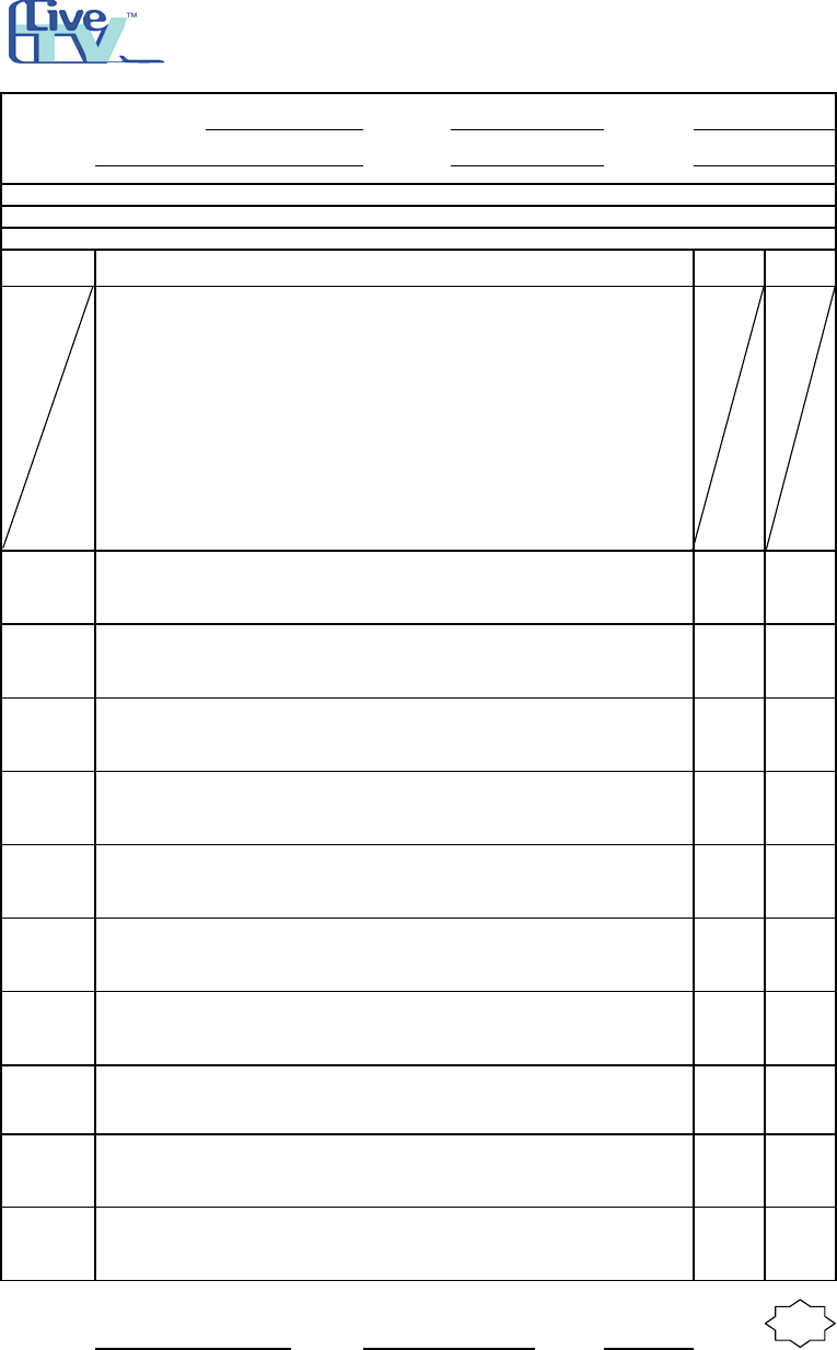
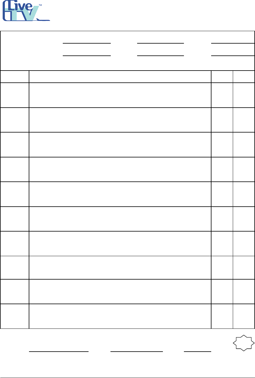
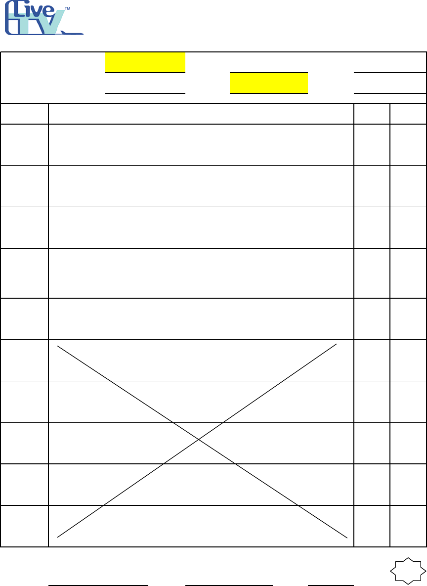
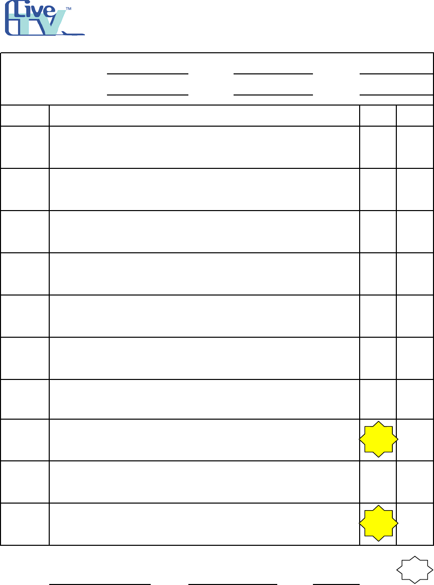
Attachment A
Example Installation Work Orders
March 27, 2003
4
S/N: TYPE A/C:
CUSTOMER: W.O. NO.: DATA:
ITEM NARRATIVE
"WADL System Elec. Install., Pg. 1 - 2."
MECH DATE
1
2
3
4
5
6
7
8
9
10
SUPERVISOR: SIGN: DATE:
Q.C.
Inspector
Stamp
LTVMNT-0025 REV A 5/10/02
(print) (sign)
PART No.or A/C TAIL No:
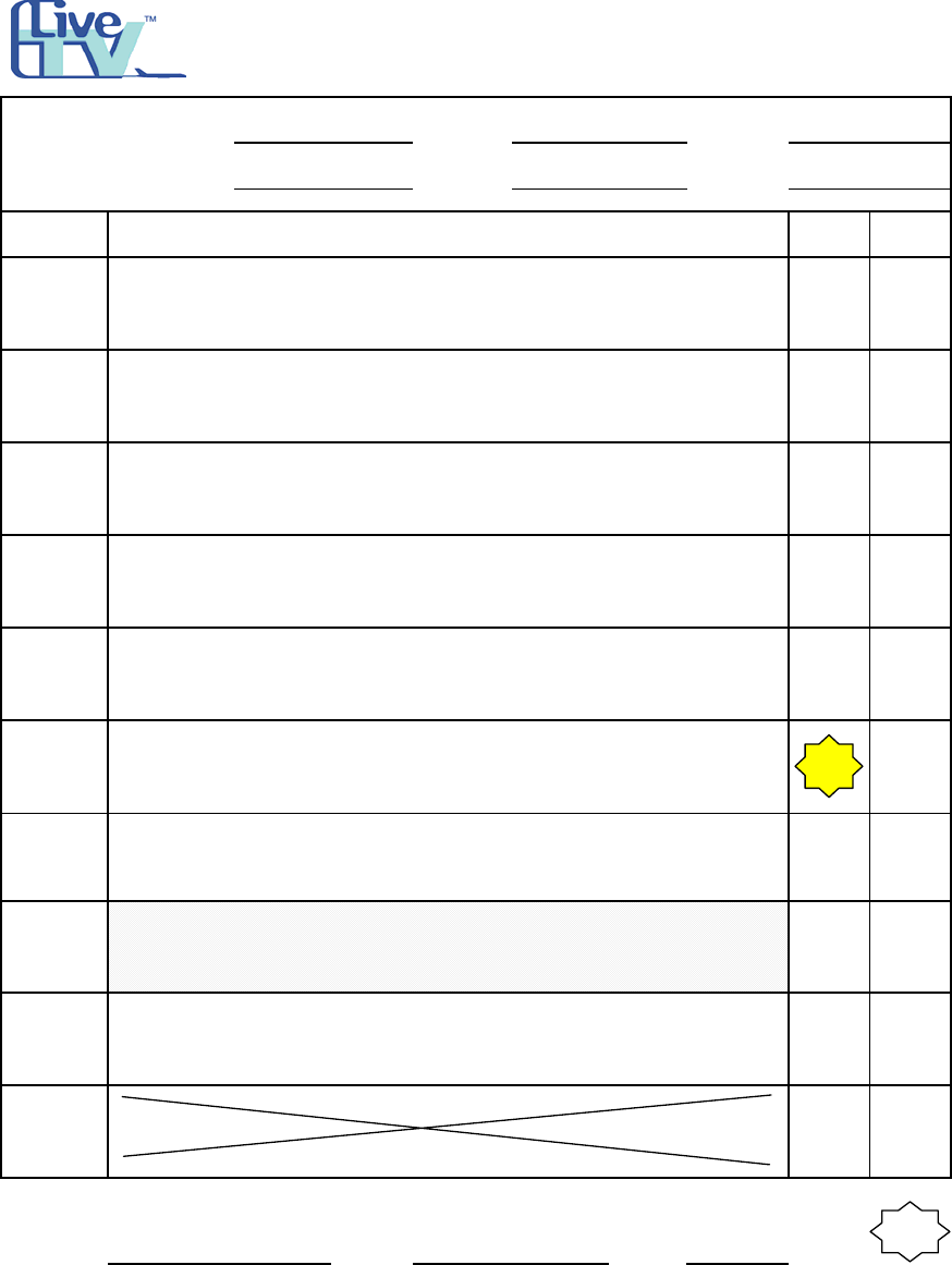
Frontier
IAW dwg LTV3092113 install WADL System wire support
structure at C63 stringer 20R.
LiveTV
WORK ORDER and IN PROGRESS
INSPECTION FORM
N906FR A-319
REPAIR STATION NO. L1IR073X
1684
IAW dwgs LTV3092090 and LTV933302 install and route coax
harness between the WADL antenna and the LNA.
IAW dwg LTV933302, install and route the coax harness between
the LNA and the PFS001 rack disconnect.
IAW dwg LTV933302 terminate WADL cable ends.
IAW dwgs LTV3092090 and LTV933302 terminate stowed wiring
IAW Airbus standard wiring practices and termination sheets.
IAW dwg LTV933302 coil and stow wiring at the 80VU rack area.
Install and route wiring harness between 9001VT to PFS001
disconnect area. Coil and stow at location area 9000VT PFS001
termination area.
Check to ensure A/C power is off. If necessary, remove the power
from the aircraft. Gain access to the 9001VT Terminal Block.
IAW dwg LTV3092090 route all system electrical cables.
IAW dwg LTV3092090 install required circuit breakers for the
WADL system.
STC # ST00788SE,
MDL 99FS933-D01 J
F90300303
Document Number: LTV3092113 Rev. N/C.
Document Number: LTV3092090 Rev. A.
Document Number: LTV933302, Sh. 104, Rev. A.
NOTE: This equipment must be installed and operated IAW provided
instructions and a minimum 20cm spacing must be provided between
computer mounted antenna and a persons body (excluding extremities of
hands, wrist and feet) during wireless modes of operation. Optional
vehicle mounted antenna must not exceed 6.0 dBi antenna gain and
should be professionally installed. This device complies with Part 15 of
the FCC Rules. Operation is subject to the complies with Part 15 of the
FCC Rules. Operation is subject to the following two conditions: (1) this
device may not cause harmful interference, and (2) this device must
accept any interference received, including interference that may cause
undesired operation. CAUTION: Any changes or modifications not
expressly approved by the party responsible for compliance could void
the authority to operate equipment.
March 27, 2003
5
S/N: TYPE A/C:
CUSTOMER: W.O. NO.: DATA:
ITEM MECH DATE
1
2
3
4
5
6
7
8
9
10
SUPERVISOR: SIGN: DATE:
Q.C.
Inspector
Stamp
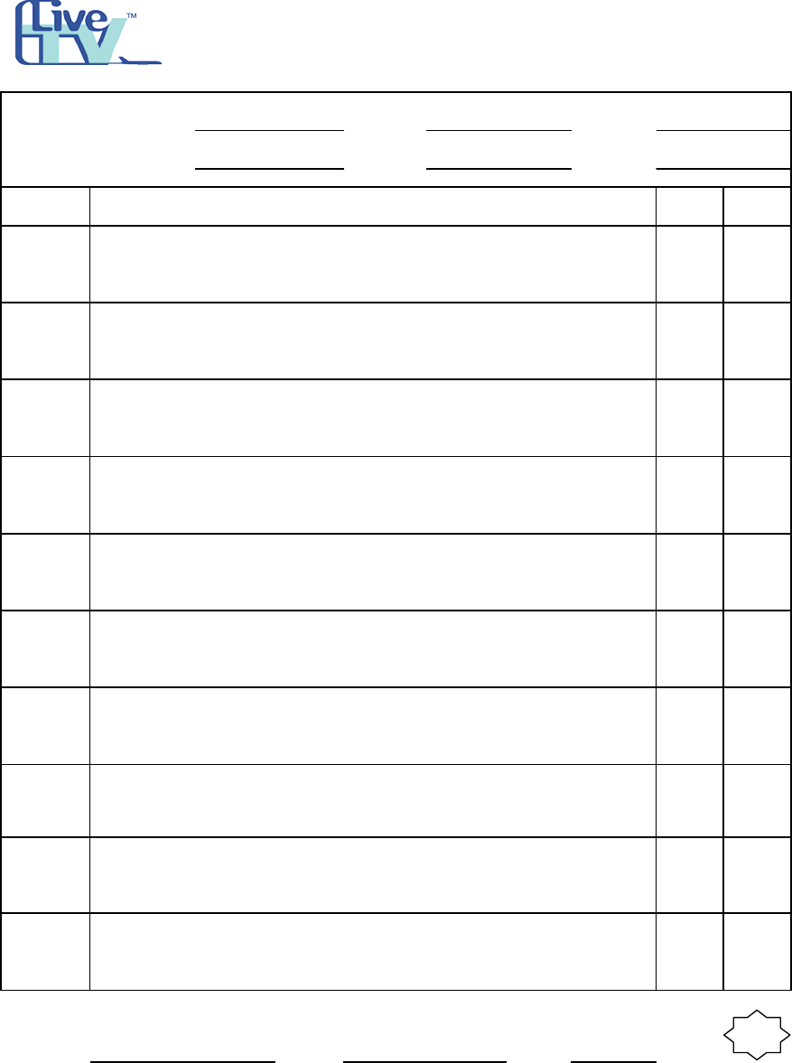
IAW Dwgs 3092090 and 3092095 and PAD 2284-920 and -923
install and route coax harness between the WADL antenna and
the LNA
IAW Dwg 2284-920 and -923 Install and route the Coax harness
between the LNA and the PFS001 rack disconnect.
Per Harris Dwg 3092095 terminate WADL cable ends.
IAW Dwgs 3092090 and 3092095 terminate stowed wiring IAW
Airbus standard wiring practices and termination sheets.
IAW Deg 3092095 Coil and Stow wiring at the 80VU rack area.
F90228302
Install and route wiring harness between 9001VT to PFS001
disconnect area, coil and stow at location area 9000VT PFS001
termination area.
PART No.or A/C TAIL No:
Frontier Airlines
Per Harris Dwg 3092113 install WADL system wire support
structure at C63 stringer 20R
LiveTV
WORK ORDER and IN PROGRESS
INSPECTION FORM
A-319
REPAIR STATION NO. L1IR073X
LTVMNT-0025 REV A 5/10/02
(print) (sign)
NARRATIVE
"wadl system,3.1, elec installation"
Check there is no power on the aircraft, if necessary, remove the
power from the aircraft.
Gain access to the 9001VT Terminal Block.
Per Harris Dwg 3092090 route in all system electrical cables.
Per Harris Dwg 3092090 Install required circuit breakers for the
WADL systems.
March 27, 2003
6
S/N: TYPE A/C:
CUSTOMER: W.O. NO.: DATA:
ITEM MECH DATE
1
XX
2
3
4
5
SUPERVISOR: SIGN: DATE:
Q.C.
Inspector
Stamp
LTVMNT-0025 REV A 5/10/02
(print) (sign)
LiveTV
WORK ORDER and IN PROGRESS
INSPECTION FORM
A319
REPAIR STATION NO.L1IR073X
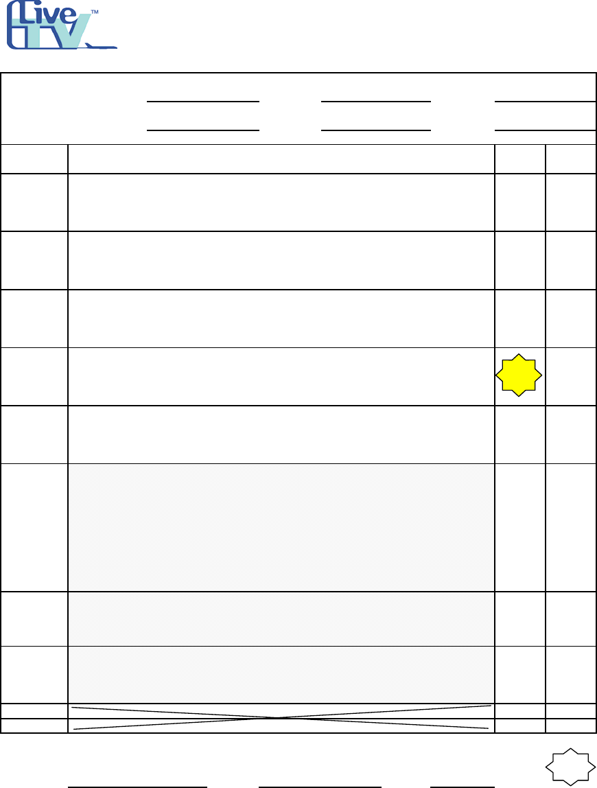
F90228302
PART No.or A/C TAIL No:
Frontier Airlines
NARRATIVE
"WADL System tally sheet"
NOT USED
Verify accomplishment WADL System Work order; 2, Mech
installation, Items 1 through 10
Verify accomplishment WADL System Work order; 3.1, Elec
Instalation, Items 1 through 12
Verify accomplishment WADL System Work order; 4, Close Up,
Items 1 through 8
Verify accomplishment WADL System Work order; 5 Activation
Items 1 through 9
March 27, 2003
7
S/N: TYPE A/C:
CUSTOMER: W.O. NO.: DATA:
ITEM MECH DATE
1
2
3
4
5
6
7
8
9
10
SUPERVISOR: SIGN: DATE:
Q.C.
Inspector
Stamp
Inspection: Inspect wadl antenna installation and doublers
per Harris dwg 3092112 install wadl LNA structure between C59
and C60, stringers 4R/5R. In accordance with Airbus SRM CH 51
airframe standard practices
Inspection: Inspect wadl LNA support structure installation.
per harris dwg 3092091 install the wadl system components
Gain access to the aircraft ceiling center line by removing the
overhead ceiling panels between C60 and C61
per Harris dwg 3092110 install the antenna structure between C60 &
C61 and stringers 1L and 1R. Ensure all workmanship is in accordance
with Airbus SRM chapter 51 airframe standard practices.
per harris dwg 3092110 install the wadl antenna.
NARRATIVE
"wadl system,2,mech installation"
Remove cargo liner sidewalls to gain access to frame C51 RH.
Note: N/A this step and steps 2, 3, and 4 if the JAES (new)
rack is installed.
per harris dwg 3092107, install the wadl rack support structure in
accordance with Airbus SRM chapter 51 airframe standard
practices
per harris dwg 3092089 install the wadl structure components
F90228302
PART No.or A/C TAIL No:
Frontier Airlines
LiveTV
WORK ORDER and IN PROGRESS
INSPECTION FORM
A-319
REPAIR STATION NO. L1IR073X
LTVMNT-0025 REV A 5/10/02
(print) (sign)
March 27, 2003
8
S/N: TYPE A/C:
CUSTOMER: W.O. NO.: DATA:
ITEM MECH DATE
1
2
XX
3
4
5
6
7
8
9
SUPERVISOR: SIGN: DATE:
Q.C.
Inspector
Stamp
LiveTV
WORK ORDER and IN PROGRESS
INSPECTION FORM
A-319
REPAIR STATION NO. L1IR073X
F90228302
PART No.or A/C TAIL No:
Frontier Airlines
Close all access panels opened in item 1.
NARRATIVE
"wadl system,5,activation"
Gain access as required to perform the following tests
Not Used
per Harris dwg 3092090 remove collars and close all WADL circuit
breakers.
per Harris dwg 3092082 Apply power to the aircraft and perform
the wadl system functional test.
Ensure all tools and any foreign material are removed from all
areas that were accessed for the wadl system..
Inspection: Ck areas for insulation blankets and foreign
materials.Give OK to close when inspection completed.
LTVMNT-0025 REV A 5/10/02
make the following logbook entry to cover the WADL activation:
"THE WIRELESS DATA LINK HAS BEEN ACTIVATED IN
ACCORDANCE WITH PART 5 OF EO 2302095."
Prepare the aircraft for return to service.
(print) (sign)
March 27, 2003
9
S/N: TYPE A/C:
CUSTOMER: W.O. NO.: DATA:
ITEM MECH DATE
11
12
SUPERVISOR: SIGN: DATE:
Q.C.
Inspector
Stamp
NARRATIVE
"wadl system,3.2, elec installation"
IAW dwg 2284-920 and -923 terminate Coax cable. Terminate all
wiring in accordance with Airbus Standard wiring Practices.
NOT USED
NOT USED
NOT USED
NOT USED
NOT USED
NOT USED
NOT USED
F90228302
NOT USED
PART No.or A/C TAIL No:
Frontier Airlines
Ensure all wiring for WADL and CSS circuit breaker provision is
installed IAW Dwgs 3092090 and 3092095 and PAD drwgs 2284-
920 and 2284-923
LiveTV
WORK ORDER and IN PROGRESS
INSPECTION FORM
A-319
REPAIR STATION NO. L1IR073X
LTVMNT-0025 REV A 5/10/02
(print) (sign)
March 27, 2003
10
S/N: TYPE A/C:
CUSTOMER: W.O. NO.: DATA:
ITEM MECH DATE
1
2
3
4
5
6
7
8
SUPERVISOR: SIGN: DATE:
Q.C.
Inspector
Stamp
Prepare the aircraft for service
Inspection: Okay to close work area panels
Close all panels removed for the WADL system installation
Make the following log book entry to cover this modification as a
MAJOR alteration of this aircraft:
"THIS AIRCRAFT HAS BEEN MODIFIED BY E.O. 2302095
INSTALLING THE WIRELESS DATA LINK IN ACCORDANCE
Complete the attached weight change notification form.
NARRATIVE
"wadl system,4 close up"
Perform continuity check on any existing aircraft wires that were
disturbed during the wadl installation.
Ensure that all tools and any foreign material is removed from all
work areas that were accessed for the WADL Installation.
In the aft cargo work areas inspect the insulation blankets prior to
closing the area for; clean & dry, not damaged, Velco tape,
attachment studs, and drain holes are clean.
F90228302
PART No.or A/C TAIL No:
Frontier Aiorlines
LiveTV
WORK ORDER and IN PROGRESS
INSPECTION FORM
A-319
REPAIR STATION NO. L1IR073X
LTVMNT-0025 REV A 5/10/02
(print) (sign)