Locks PS902 Instructions 106440
User Manual: Locks PS902 Instructions Mayflower Sales - Schlage Electronics
Open the PDF directly: View PDF ![]() .
.
Page Count: 4
*44487023*
44487023
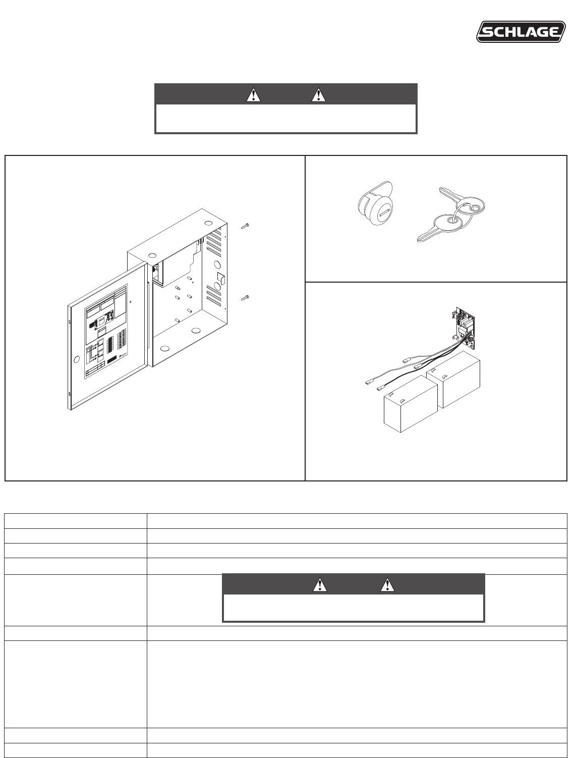
These instructions cover the following parts:
PS902 Power Supply Specications:
Input 120/240 VAC, 1.1 A, 50/60Hz, High Voltage Class 1 Wiring Required
Output 2 Amp DC @ 12/24 VDC
Enclosure 14” H x 12” W x 4” D (8 knockouts, 1/2” or 3/4” )
Temperature Range 32°-120° F (0°- 49° C)
Fuse F1, T3.15A
250VAC
Compliance UL 294, ULC-S318, RoHS, & FCC Part 15, Class 2 Output
Compatible Boards
(Optional, 1 board maximum)
900-2RS
900-2Q
900-4R
900-4RL
900-8F
900-8P
Fire Alarm Input Board (Optional) 900-FA
Battery Backup Board (Optional) 900-BB
PS902 Power Supply - Pages 1-3
900-KL Keylock (optional) - Page 2
900-BB Battery Backup (optional) - Page 3
F1
DANGER
!
!
DANGER:
!
WARNING:
!
WARNING:
INST. INSTRUCTIONS - 24125007
INST. INSTRUCTIONS - 44487098
INST. INSTRUCTIONS - 44487106
INST. INSTRUCTIONS - 44487080
INST. INSTRUCTIONS - 44487106
INST. INSTRUCTIONS - 44487106
INST. INSTRUCTIONS - 44487072
INST. INSTRUCTIONS - 44487064
Power Supply
PS902
Installation Instructions
DANGER
To avoid risk of electric shock, turn off AC power before
installing or servicing PS902 power supply
CAUTION
For protection against risk of re, replace fuse with same
type and rating
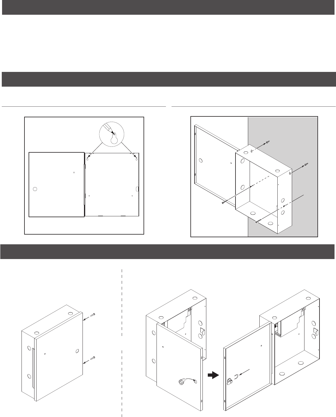
1 Mount power supply
1a Mark 2 Top Holes 1b Secure Enclosure with 4 Screws
Mounting notes
The PS902 must be installed in accordance with the article 760 of the National Electrical Code or NFPA 72, Canadian Electrical Code, or
any other applicable codes.
Install the PS902 indoors within the protected premises.
Check national and local codes for additional installation requirements.
Enclosure must be rmly mounted to a solid surface using hardware suitable for the surface.
xx
2 Secure enclosure door
If No Keylock
Enclosure will be secured with 2
screws as shown (done as last step)
If Keylock
Remove knockout and insert key cylinder, then slide in clip
ab
OR
Board not shown for
clarity
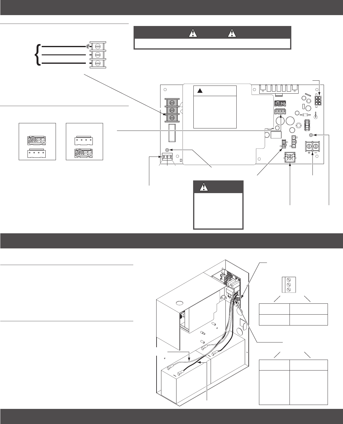
3 PS902 setup and testing
4 Install 900-BB battery backup (If Included)
DC Output
(Red LED)
900-FA
Connector
12/24 VDC
Output
Terminals
Fire Alarm Jumper
Remove when
900-FA installed
F1
AC Input
(Green LED)
AC Monitor
Active when AC present
and F1 fuse not open
(Form C dry contacts)
24
12
NC C NO
900-BB Connector
High Voltage
If main board must be
removed, turn off AC power
and wait 8 minutes before
removal
Do not remove this cover, no
serviceable parts
DANGER
!
3a
NEU
LINE
Green (Ground)
White (Neutral)
Black (Hot)
AC (In)
120/240
VAC
AC Input
OR
12 VDC
Output Setting
24 VDC
Output Setting
Battery 1 Battery 2
Black Wires = (-)
+
+
BB LED
(Amber)
On-Solid
AC On
Batteries
Charging
On-Blinking
AC Off
Batteries
Supplying
Power
Battery Supervision Terminals
(Form C Dry Contacts)
Active
AC On
Inactive
AC Off
(Shown
AC Off)
NO
C
NC
Red Wires = (+)
5 Turn on AC breaker to test power supply
• Verify AC LED is On = GREEN
• Verify DC LED is On = RED
• Verify BB LED (if applicable) is On = AMBER
Minimum of 1/4” separation
between AC and DC wiring as
well as power limited and non-
power limited.
Note:
Refer to 900-BB instructions for additional info
3a Connect AC Wiring
3b Use Jumper to Select 24 VDC or 12
VDC Output
4a Place Batteries in Box with Terminals to
the left
4b Attach Wire from Battery Board
Red wires = (+)
Black wire = (-)
Note: allow 24 hours for batteries
to fully charge
DANGER
If AC LED is
off, turn AC
breaker prior
to checking F1
fuse
DANGER
Ensure AC breaker is turned off
© Allegion 2014
Printed in U.S.A.
44487023 Rev. 01/14-c
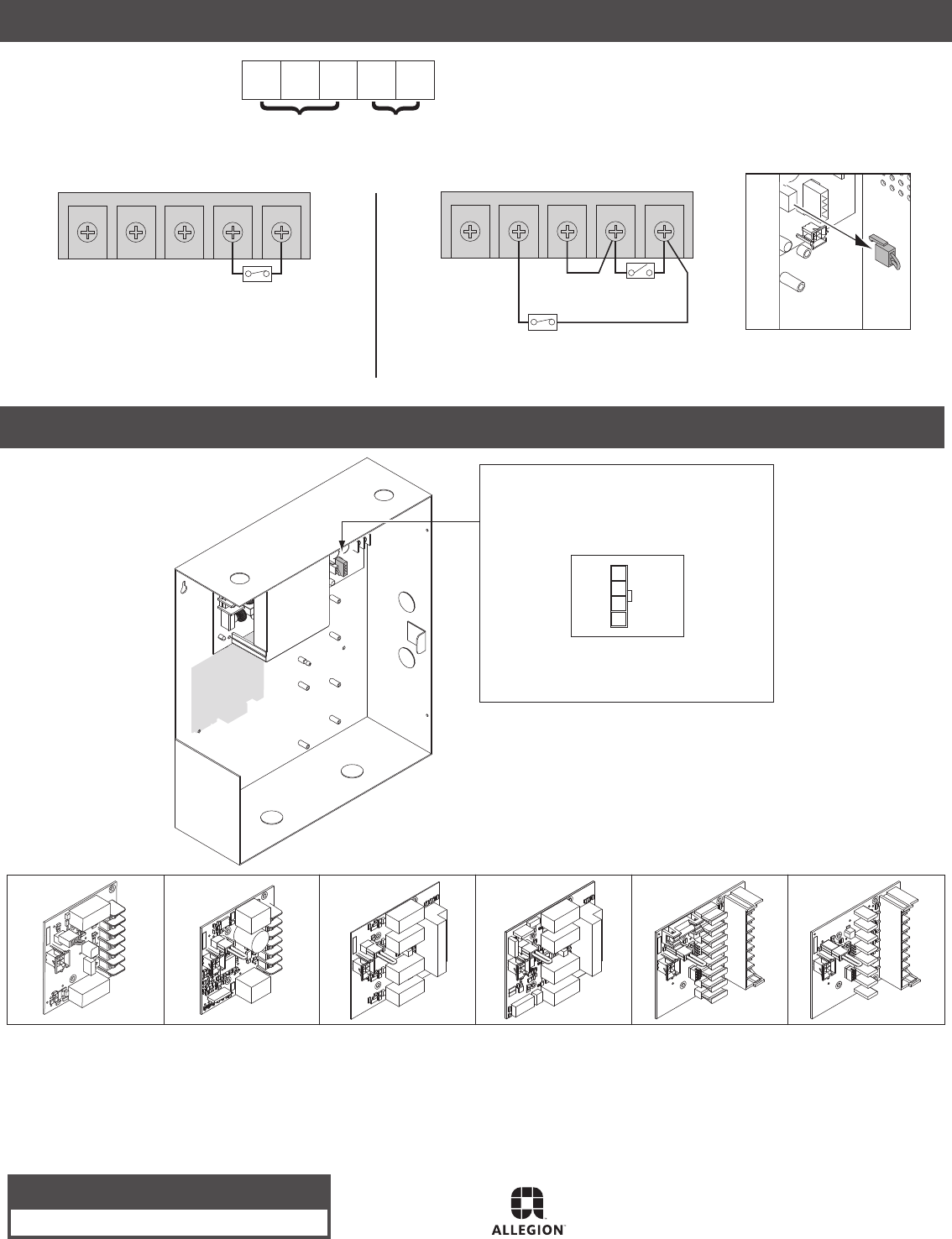
Option Board to be Plugged
into Option Connector
• See option board installation instructions
for wiring info
Option 1
900-2RS
(2 Relay)
900-2Q
(2 Relay w/com)
900-4R
(4 Relay)
900-4RL
(4 Relay w/logic)
900-8F
(8 Zone
Distribution-fuse)
900-8P
(8 Zone
Distribution-PTC)
Available option boards:
6 Wire 900-FA (re alarm board) if included
NC FA2FA1NOC
One 900-FA Board - Automatic Reset
NC FA2FA1NOC
One 900-FA Board - Manual Reset
Supervision Output
Contacts Shown FA Active (open)
Fire Alarm Input
NC C NO FA1 FA2
Terminal Definitions
Fire Alarm Contact
Closed = no fire
Open = fire
Manual Reset
(Temporarily close to reset)
Fire Alarm Contact
Closed = no fire
Open = fire
Note: If FA is installed on PS902:
• Verify jumper J13 is removed
• Power will be removed from
PS902 when fire alarm is active
NOTE: When installation is complete, secure enclosure door with screws (provided) or keylock
Customer Service
1-877-671-7011 www.allegion.com/us
Option Boards
Refer to appropriate instructions if any board
shown below is factory-installed
When powering (2) QEL’s with a PS902, both cannot be
activated at the same time, they must be sequenced.
Latchbolt retraction of (2) sequenced QEL’s requires more
than 1 second to complete.
For double door QEL applications with auto operators, it is
recommended to use a PS904, 906, or 914 power supply.
1.
2.
3.
Notes:
Refer to 900-FA instructions
for additional info
