Contents
- 1. User Manual - Part 1
- 2. User Manual - Part 2
User Manual - Part 1
USER MANUAL

CONTENTS 2STARex MANUAL
CHAPTER I: INTRODUCTION
1.1 OVERVIEW ................................4
1.2 KEY CONCEPTS ...........................6
1.3 BROWSER REQUIREMENTS .................6
1.4 MOBILE REQUIREMENTS ....................6
CHAPTER II: BASICS
2.1 QUICK START .............................7
2.1.1 ACCESSING THE STARFLEX WEB INTERFACE . 7
2.1.2 “PHONE-HOME” REGISTRATION ............. 8
2.1.3 HOME PAGE ............................. 17
2.1.4 LOGGING INTO STARFLEX ................ 23
2.1.5 ABOUT .................................. 26
2.1.6 SETTINGS ............................... 30
2.1.7 CLIENT LIST ............................. 35
2.1.8 LOGGING OUT OF STARFLEX .............. 37
2.1.9 BASIC MODE ............................ 38
2.1.10 ADVANCED MODE ....................... 41
CHAPTER III: RFID SETTINGS
3.1 RFID SETTINGS ............................55
3.1.1 AUTO DISCOVERY ........................ 57
3.1.2 ANTENNAS .............................. 58
3.1.3 ENODE 1 - ENODE 2 ...................... 58
3.1.4 PROFILES ............................... 59
3.1.5 2ND RECEIVE ANTENNA MODE ............. 60
3.1.6 PHYSICAL LAYER SETTINGS ............... 60
3.1.7 PATTERN ............................... 61
3.1.8 BASIC PROGRAM RUNNING ................ 62
CHAPTER IV: TAG VIEWER
4.1 TAG VIEWER ..............................63
1
2
3
4
CONTENTS 3STARex MANUAL
CHAPTER V: NETWORK SETTINGS
5.1 NETWORK SETTINGS .......................72
CHAPTER VI: CONTROL
6.1 CONTROL .................................75
6.1.1 DEFAULT RFID SETTINGS ................. 76
6.1.2 REBOOT ................................ 77
6.1.3 FACTORY RESTORE ...................... 77
6.1.4 FIRMWARE UPDATE ...................... 78
6.2 ANTENNA TEST ............................79
6.3 GPIO TEST ................................82
6.4 MQTT CONFIGURATION ....................85
6.5 LICENSE MANAGER ........................87
APPENDIX
FCC Notice, STARex and eNode ................90
6
5

4
CHAPTER I: INTRODUCTION STARex MANUAL
OVERVIEW
The STARex reader combines the high performance and real-time location
capabilities of the STAR distributed excitation architecture with highly exi-
ble new options for antenna topology and software integration.
While suitable for use in both indoor and outdoor scenarios, STARex is
optimized for cost effective, easy-to-deploy solutions for enclosed environ-
ments such as real-time inventory management, ambulatory patient ow
management and asset tracking in retail, healthcare and industrial scenar-
ios. Very high receiver sensitivity enables the STARex to perform well in
indoor applications where reections from metal shelves, equipment and
xtures interfere with line-of-sight between the reader and the tag reducing
read rates for other readers.
1.1 OVERVIEW
CHAPTER I:
INTRODUCTION
1

5
CHAPTER I: INTRODUCTION STARex MANUAL
OVERVIEW
The STARex software architecture is optimized for simplicity and resilience in order to enable fast deployment of robust distributed systems. For tag data,
STARex features native support for the lightweight MQTT device protocol. To simplify and speed integration, STARex provides a RESTful API for control
and status. Users can implement business logic software directly on the reader using this RESTful interface, or by using the modern and ubiquitous node.
js web framework. Out-of-the-box the reader connects to ViZix.Mojix.com, enabling users to have their STARex up and sending tag data into the cloud in
minutes. An intuitive web interface simplies conguration of individual readers.
HIGH PERFORMANCE HARDWARE DESIGN
• Distributed excitation architecture scales efciently to 48 antennas per reader
• Dual receivers provide the highest sensitivity available in a 4-port reader
• Compliant with EPC Gen2V2, ISO 18000-6c.
• TrueRTLS™ location precision when used with the Mojix RTLS MCON appliance
FLEXIBLE SOFTWARE ARCHITECTURE
• RESTful API
• JSON and MQTT payload options
• Node.js support
• Support for local execution of user code via RESTful API or shell access (expert)
• Automatic phone-home registration process speeds
• Compatible with ViZix IoT software platform
• Easy automatic “phone-home” setup process out of the box
Note: STARex should be installed by Mojix trained professionals familiar with radio frequency equipment and regulatory requirements. To maintain
regulatory compliance, use only antenna and cable supplied with the unit or approved by Mojix, and ensure that output power does not exceed regulatory
limits.
Caution: To comply with radio frequency exposure compliance requirements, a separation distance of 20 cm must be maintained between reader antennas
and all persons.
6
CHAPTER I: INTRODUCTION STARex MANUAL
1.3 BROWSER REQUIREMENTS
1.4 MOBILE REQUIREMENTS
KEY CONCEPTS, BROWSER REQUIREMENTS & MOBILE REQUIREMENTS
For best results, Mojix recommends the most recent version of Chrome.
The iOS supported is version 8 or higher.The optimum resolution of the screen recommended for mobile and touch devices is 768x768, the application
works correctly in devices with less resolution, however a complete view of certain sections such as the Tag Viewer might be impacted at user experience
level.
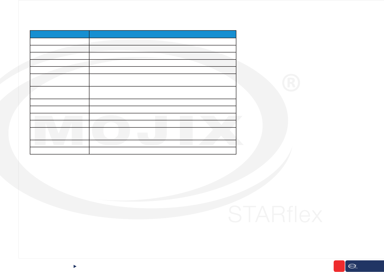
There are some key concepts mentioned throughout this manual that will be useful to understand. The following glossary of acronyms are used in many
of the sections.
1.2 KEY CONCEPTS
TERM DEFINITION
API Application Programming Interface
CSV Comma-separated Values
dBm Decibel-milliwatt
DHCP Dynamic Host Conguration Protocol
DNS Domain Name System
eNode A reliable, autonomously operated simple RF repeater designed to excite all
EPC UHF Gen 2 RFID tags within their designated interrogation spaces.
EPC Electronic Product Code - An ultra-low-cost RFID tag containing a 64-bit or
96-bit unique ID codes.
LED Light-emitting Diode
MAC Number Media Access Control Number
NTP Network Time Protocol
RFID Radio Frequency Identication
Tag An RFID device capable of receiving reader signal and returning data to the
reader.
TxID Transmit Antenna
UI User Interface

7
CHAPTER II: BASICS STARex MANUAL
QUICK START Accesing The STARex Web Interface
2
CHAPTER II:
BASICS
2.1 QUICK START
2.1.1 ACCESSING THE STARFLEX WEB INTERFACE
After the STARex has been connected to a network and powered on, the next
step is to access the STARex’s Web interface to perform the conguration tasks
and verify the STARex is reading RFID tags.
To access the Web interface, specify the following URL in your Web browser:
http://169.254.y.z
In case that no DHCP service is available, a temporary static IP address is as-
signed for a period of ten minutes. Review the sticker label printed on the STAR-
ex unit. The IP address printed on the label will look like this: 169.254.y.z where
y and z will vary from unit to unit.
8
CHAPTER II: BASICS STARex MANUAL
2.1.2 “PHONE-HOME” REGISTRATION
The STARex is precongured to self-register with the Mojix Vizix cloud application if the unit is able to connect to the Internet. The purpose of this regis-
tration is to enable users to have a simplied, cloud managed solution for managing STARex readers. Vizix provides the capability to bring up a STARex
reader and process RFID tag read data in a matter of minutes.
Registering the Device in ViZix
The STARex device must be connected to the Internet so it activates the phone home to create its corresponding hierarchy in the ViZix platform. The
device will be created as a new STARex Thing which will have the discoveryDate and the association elds of the STARex left blank until the device is
claimed in the registration platform.
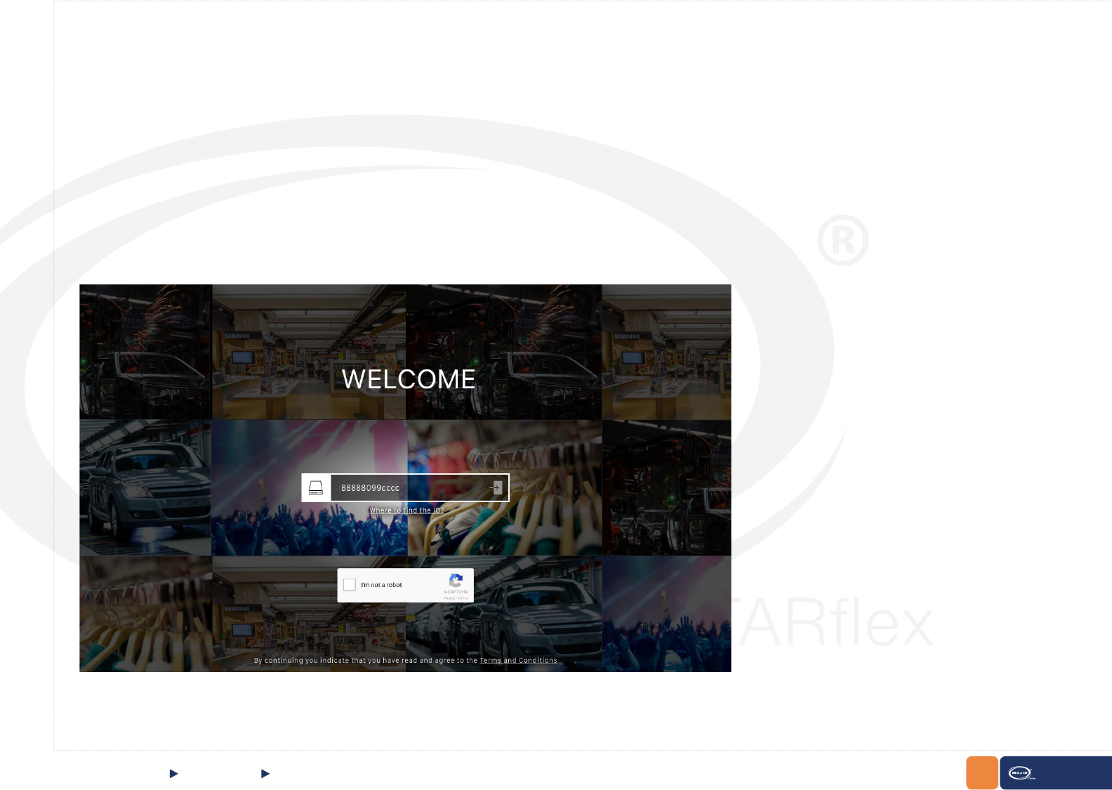
The Registration Wizard
In a browser window go to the Registration Wizard address and the login page will be shown. To login, it is necessary to enter the serial of the STARex
device (already registered in ViZix), this serial should be the same unique code of the device which could be its barcode (usually located at the back of the
device) or its MAC address.
Enter the serial with which the device is registered in ViZix in the ID/Serial Number eld, check the I’m not a robot captcha, complete its challenge and click
on the left arrow of the eld to start the wizard.
QUICK START “Phone-Home“ Registration
9
CHAPTER II: BASICS STARex MANUAL
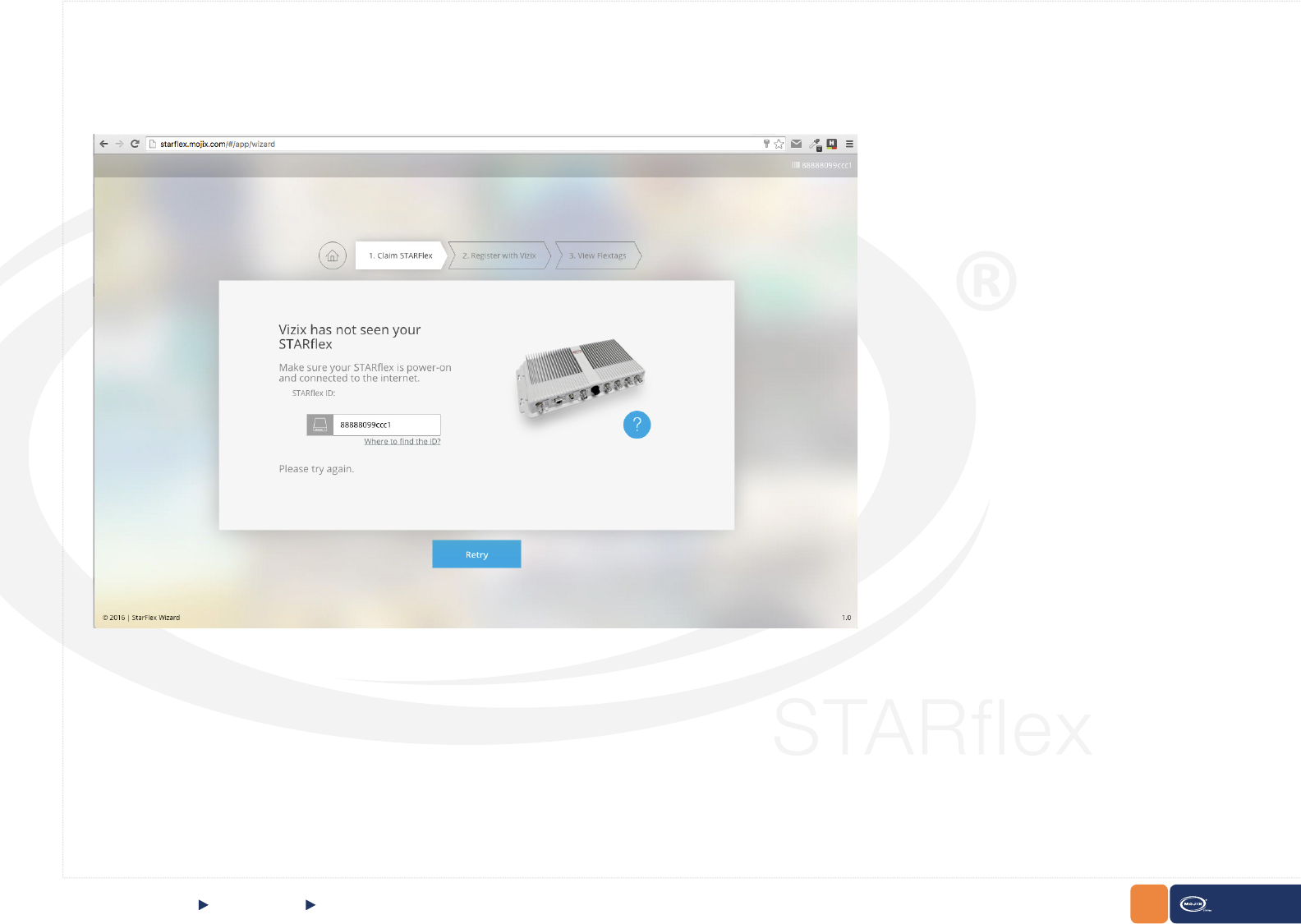
Claim STARex
The wizard rst veries that the device is registered in the ViZix platform. If the serial of the device entered is not registered in ViZix or the serial is incorrect,
the rst step will show a message indicating that ViZix has not seen the STARex (it means that is not registered in the ViZix platform). Enter the correct
serial code and click on Retry to verify once again that the STARex is registered in ViZix.
QUICK START “Phone-Home“ Registration
10
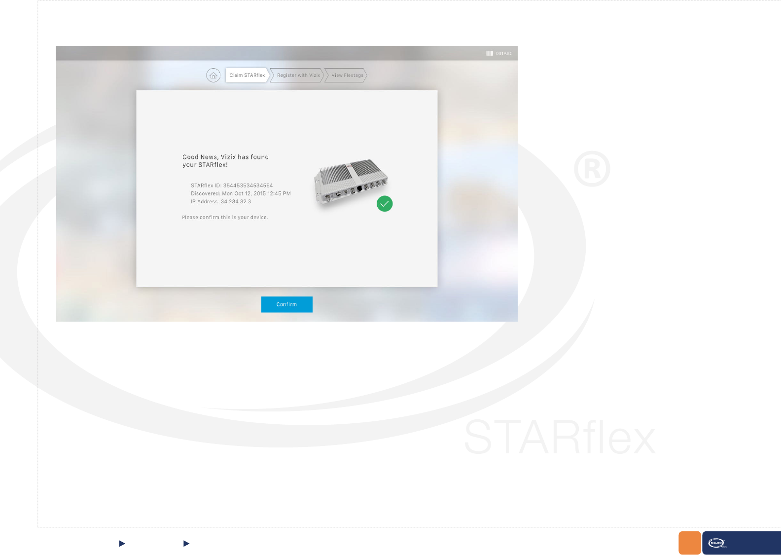
CHAPTER II: BASICS STARex MANUAL
If the entered serial is correct, then the following window will be shown in the rst step of the wizard:
QUICK START “Phone-Home“ Registration
11
CHAPTER II: BASICS STARex MANUAL
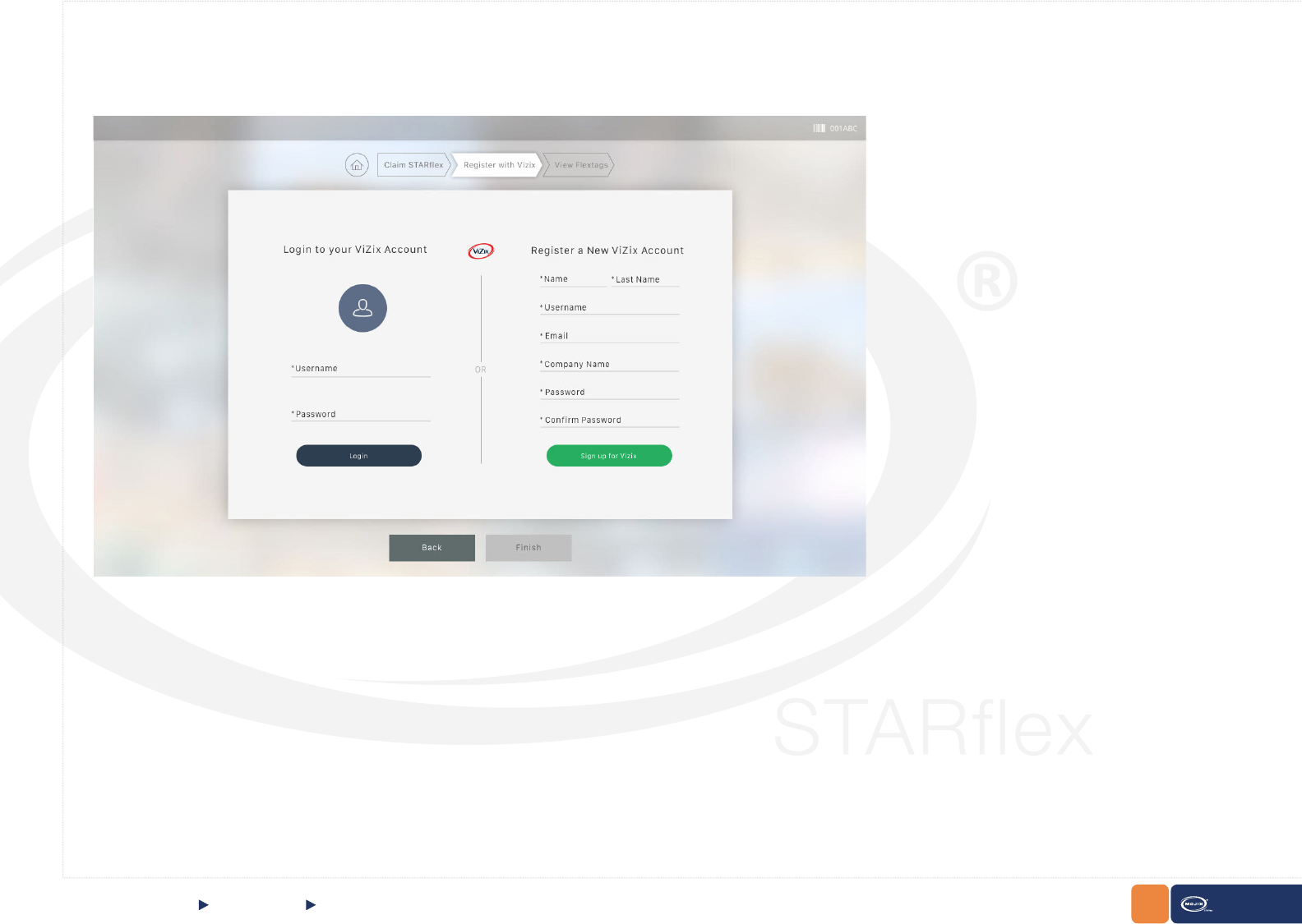
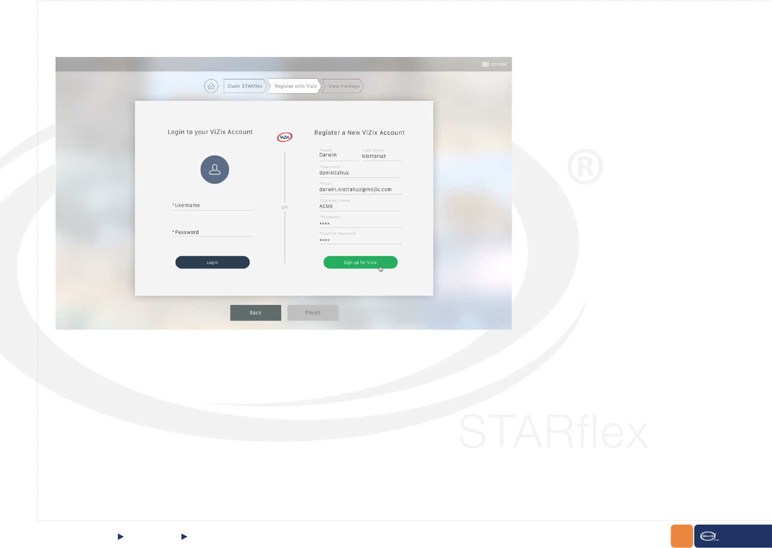
Register with ViZix
To claim the device it is necessary to have a user registered in the ViZix platform. In the second step of the registration there are two options to connect to
ViZix; the rst one is using an already registered user in ViZix and the second is to register to ViZix by creating a new account.
If using an existing account in ViZix then, enter the corresponding credentials in the Login to your ViZix Account section at the left side and click on Login
to claim the device with that user.
QUICK START Register with ViZix
12
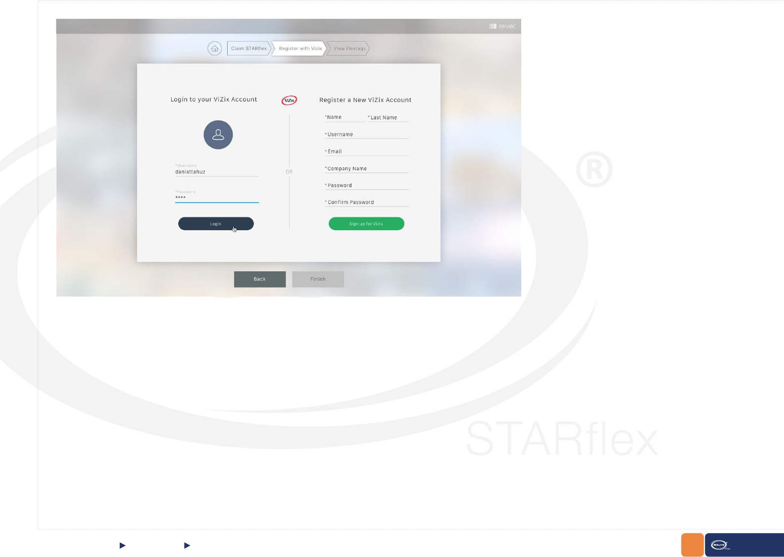
CHAPTER II: BASICS STARex MANUAL
If the account exists in ViZix, the information of the ViZix user, his/her name, last name, username, email and the company name will be shown.
QUICK START Register with ViZix
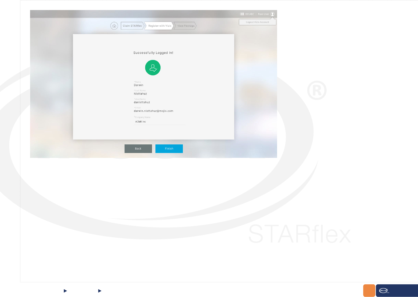
13
CHAPTER II: BASICS STARex MANUAL
Click on Finish to go to the nal step.
QUICK START Register with ViZix
14
CHAPTER II: BASICS STARex MANUAL
On the other hand, to create a new account in ViZix, ll in the form at the right side in the Register a New ViZix Account panel and click on Sign up for ViZix
to register the new account
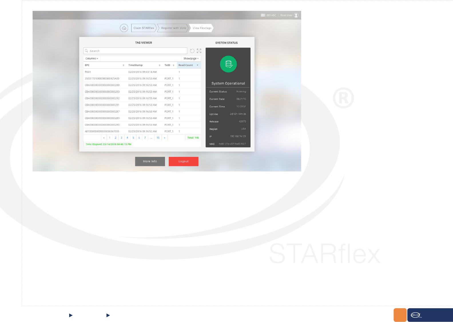
View Flextags
The last step shows the tags associated to the STARex as a test that the connection is valid. The information of the device is shown in the right panel and
the information of the tags associated to the device is shown in the left panel.
QUICK START Register with ViZix, View Flextags
15
CHAPTER II: BASICS STARex MANUAL
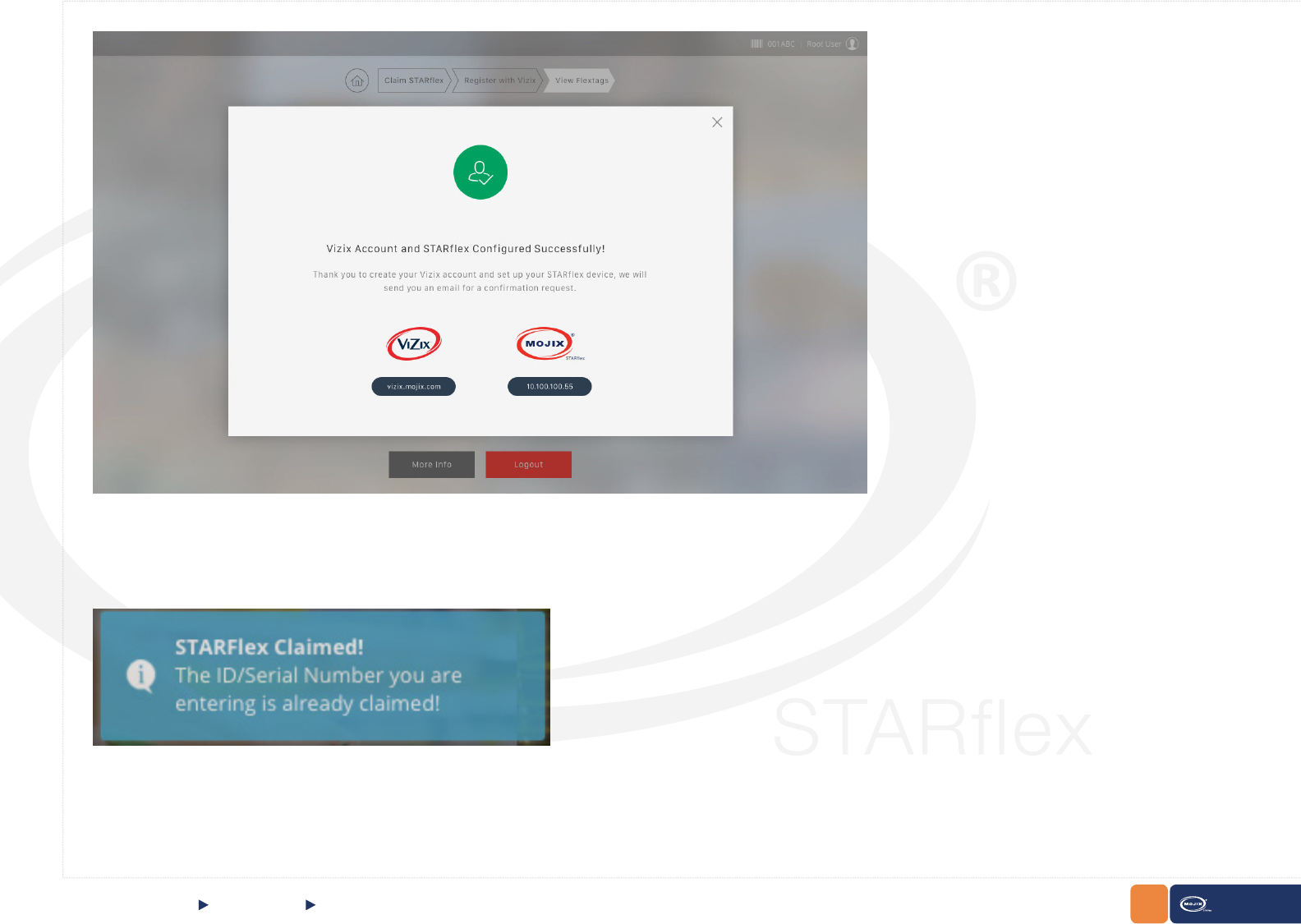
Click on More Info to open the window with the message indicating that the ViZix account and STARex congured successfully. This window has two
options to continue to the ViZix console (at the left) or go to the micro stack console of STARex (at the right).
QUICK START View Flextags
16
CHAPTER II: BASICS STARex MANUAL
QUICK START View Flextags
Close this window by clicking on the X icon at the top right corner of the window or by clicking on any space out of the window.
To nish the registration process, click on the Logout button and the login page will be shown again. If the ID/serial number of an already claimed device is
entered in the platform, a message indicating that the STARex as already been claimed will be shown.
17
CHAPTER II: BASICS STARex MANUAL
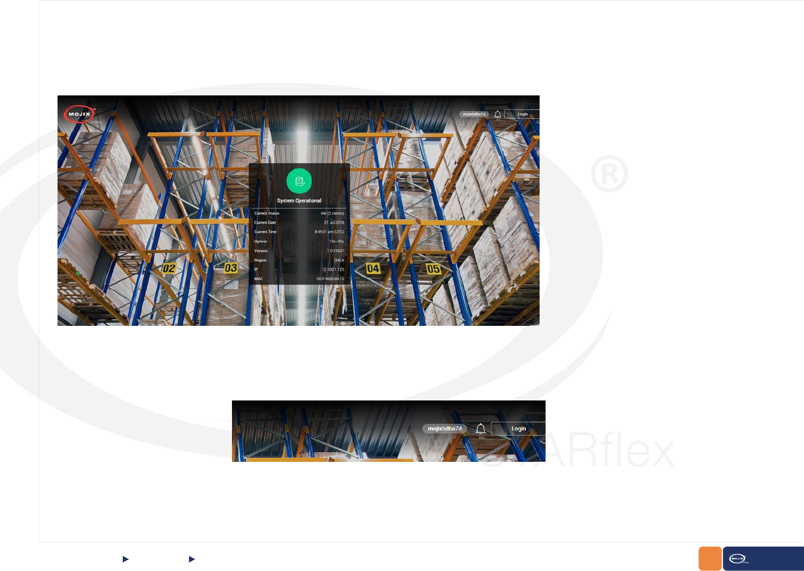
2.1.3 HOME PAGE
Once you access to the STARex Web Interface, the home page is displayed.
QUICK START Home Page
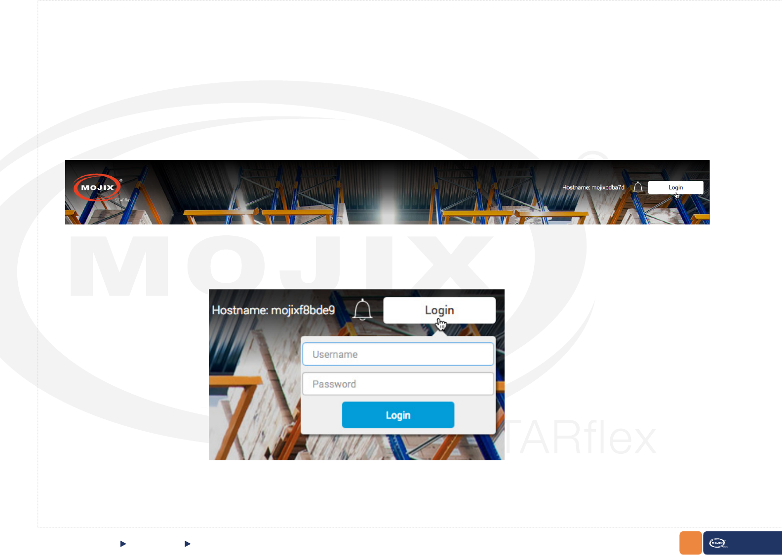
At the top of the page the default hostname of the corresponding STARex is located, the bell icon showing the number of new notications and the button
to login to the application are displayed.
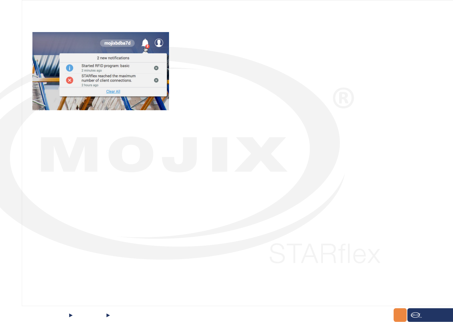
Clicking on the bell icon displays a list with the available notications (exceptional conditions like low ash memory warnings, etc). It is possible to clear the
list of messages one by one or all at once.
18 STARex MANUAL
CHAPTER II: BASICS QUICK START Home Page
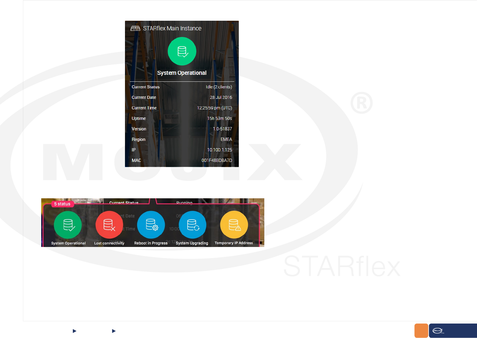
In the main menu, there is the information related to the STARex explained below:
a. System Operational
This shows the current status of STARex along with information related to the server.
19 STARex MANUAL
QUICK STARTCHAPTER II: BASICS
1. System Operational, (Green with a check mark) is indicated when the system is running correctly but no RFID program is running.
2. Lost connectivity, (Red) is indicated when there is no connectivity with the STARex.
3. Reboot in progress (Blue) indicated when rebooting
4. System Upgrading (Blue) indicated when the system is Upgrading
5. Temporary IP Address, (Yellow) is indicated when the IP address is temporary (10 Minutes) and the operating IP address has not been congured yet.
6. System Operational, (Green with a running engine) is indicated when the system is running correctly and a RFID program is running as well.
At the top of the System Operational information, an icon showing the current status of the STARex. There are 6 possibilities:
Home Page
20
CHAPTER II: BASICS STARex MANUAL
When the cursor is hovering the status icon the following message will appear: Go to Network
Settings to change the conguration to DHCP or static IP address
This only appears when the Status is Temporary IP Address.
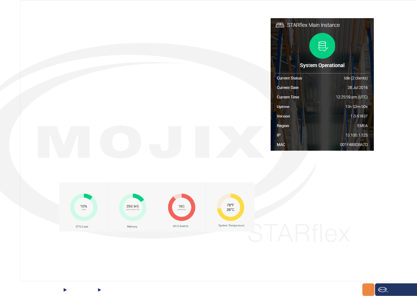
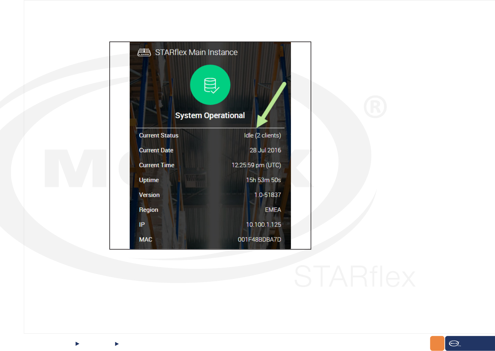
Additionally, further information can be presented:
• Current Status: It has two possible values: “Running”, when a RFID program is running
and “Idle” if no RFID programs are running. The number of clients is also displayed.
• Current Date. It shows the current date according to the Time Zone congured inside the
Network Settings conguration.
• Current Time. It shows the current time according to the Time Zone congured inside the
Network Settings conguration.
• Uptime: The current time the STARex has been up and running.
• Version: The release version of this STARex.
• Region: Shows the current frequency regulation of the STARex.
• IP: The IP address congured or assigned to this STARex.
• MAC: The mac address of this STARex.
QUICK START Home Page
Following, the STARex status section is represented in four graphics that display information about
the CPU load, the disk space, the number of events per second and the system temperature. The
graphics will be displayed in three possible colors: red, yellow or green. The color will depend on the
health status at that moment, green color means optimal performance, yellow color means warning
and red color means error.
For example, the CPU load at optimum is under 80%, above that point the status is indicated as warning until 95% is reached which is indicated as an
error. For the memory space status the optimum is above 70%, between 30% to 70% the status is indicated as warning and below 30% is indicated as
an error. For the events per second the status color optimum is below 400 events/sec, the warning between 400 and 700 and above 700 is error. For the
system temperature the values are displayed in Fahrenheit and Celsius degrees, the optimum is under 70 Celsius degrees, the warning between 70 and
85 degrees, and above 85 is an error.
b. Server Information
21
CHAPTER II: BASICS STARex MANUAL
QUICK START Home Page
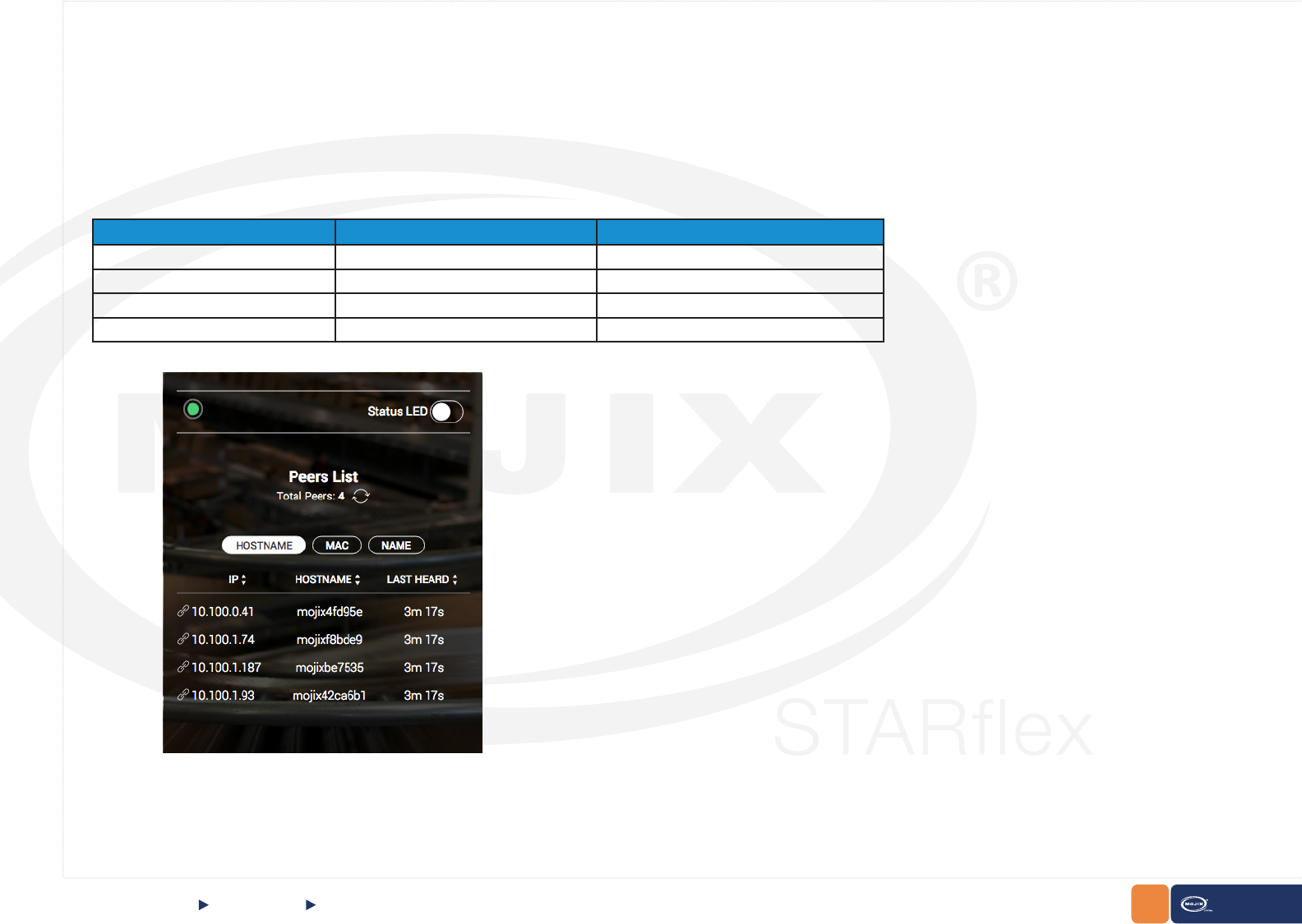
The details section displays a list of other STARex’s discovered on the network.
API Status LED
On the top of the STARex is a LED indicator and a switch named “Status LED”. There are four possible LED indications reported from the API (GET cong/
led): on, off, blink or keep alive.
The behavior of all combinations of the LED are described in the table below.
When the user switches the “Status LED” switch to:
ON: the LED will blink (PUT request to cong/led/blink in API)
OFF: the LED will ash every 3 secs. (PUT request to cong/led/keepAlive in API).
c. Peers List
LED Status from API “Status LED” Switch LED
ON OFF Green
OFF OFF Gray
Blink ON Green Blinking
Keep Alive OFF Green ashing every 3 secs
22
CHAPTER II: BASICS STARex MANUAL
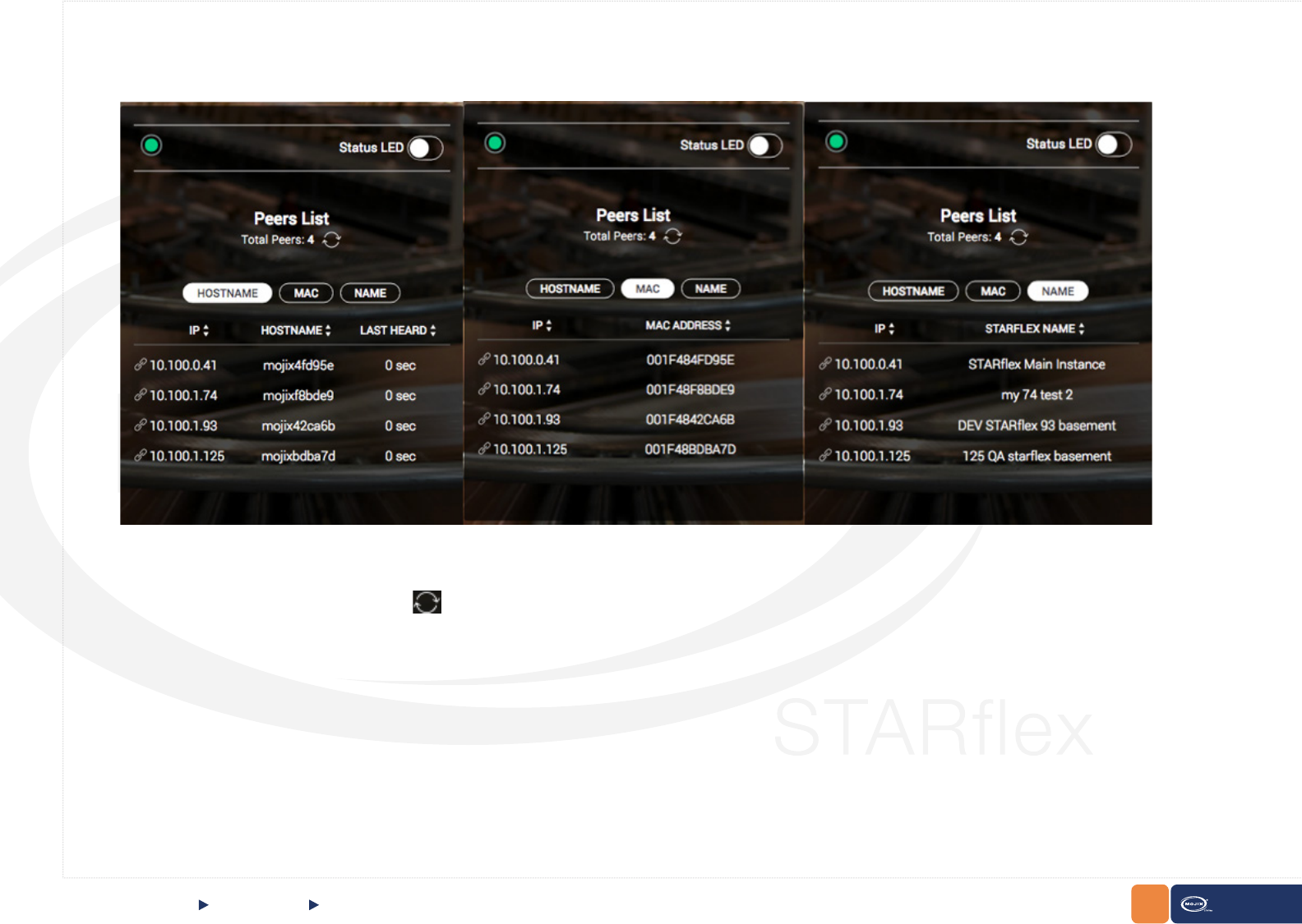
Next to Total Peers there is a refresh button . The refresh button sends a broadcast and returns information about all STARexes that respond.
3 buttons to switch between HOSTNAME, MAC and NAME have been added.
QUICK START Home Page
23 STARex MANUAL
CHAPTER II: BASICS
2.1.4 LOGGING INTO STARFLEX
There are two modes to log in to STARex: Basic Mode and Advanced Mode.
Basic Mode:
Perform the following procedures to log into the STARex user interface in basic mode:
1. Click on the login button on the top right side.
2. Enter the username in the Username eld.
3. Enter the password in the Password eld and click on the Login button or press enter.
QUICK START Logging into STARex
24 STARex MANUAL
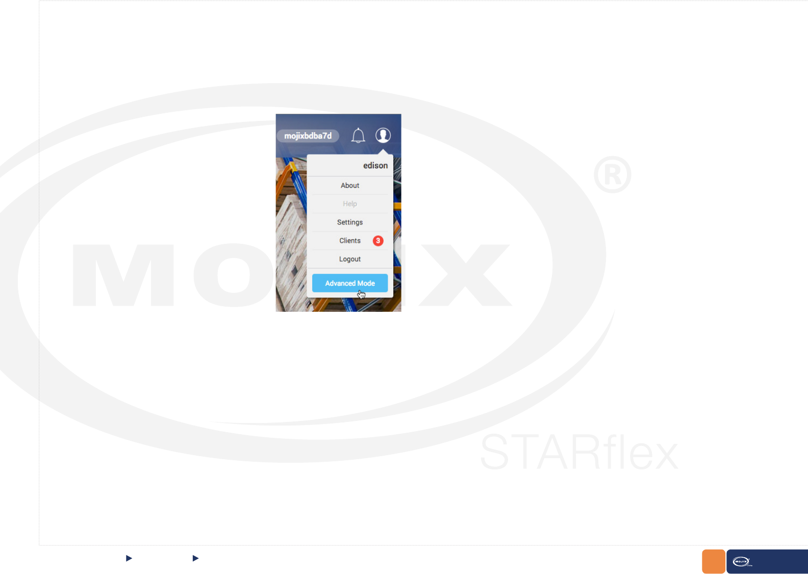
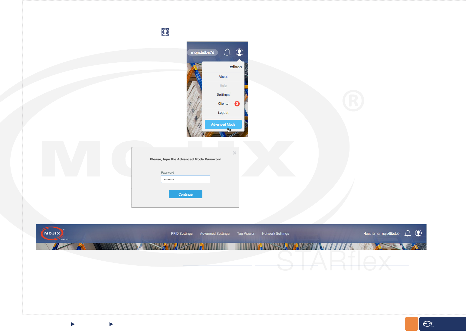
Advanced Mode:
Perform the following procedures to log into the STARex user interface in advanced mode:
1. Once logged in basic mode click on the User Icon on the top right side and then click on the Advanced Mode button.
2. Enter the password in the Password eld and click on the Continue button or press enter.
CHAPTER II: BASICS QUICK START Logging into STARex
Note: The Advanced Mode password is disclosed only to professional installers.
25 STARex MANUAL
The default credentials for the STARex UI are provided below:
Username Password Security Level
edison m0j1xInc Intermediate
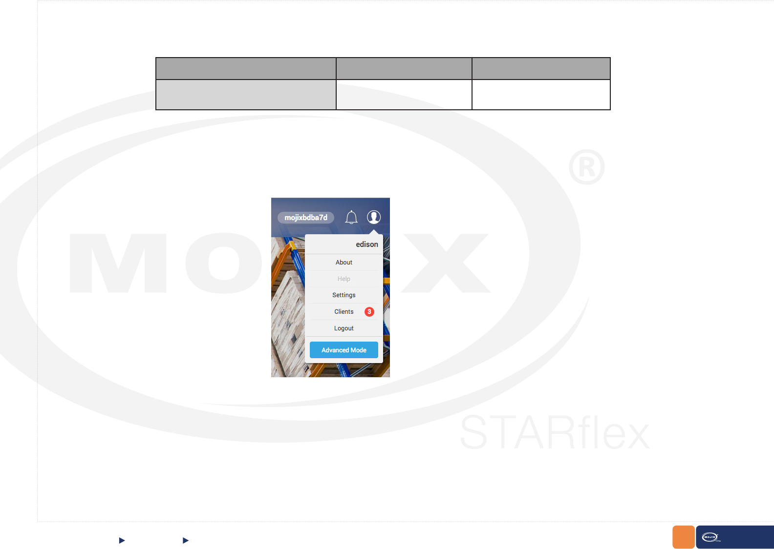
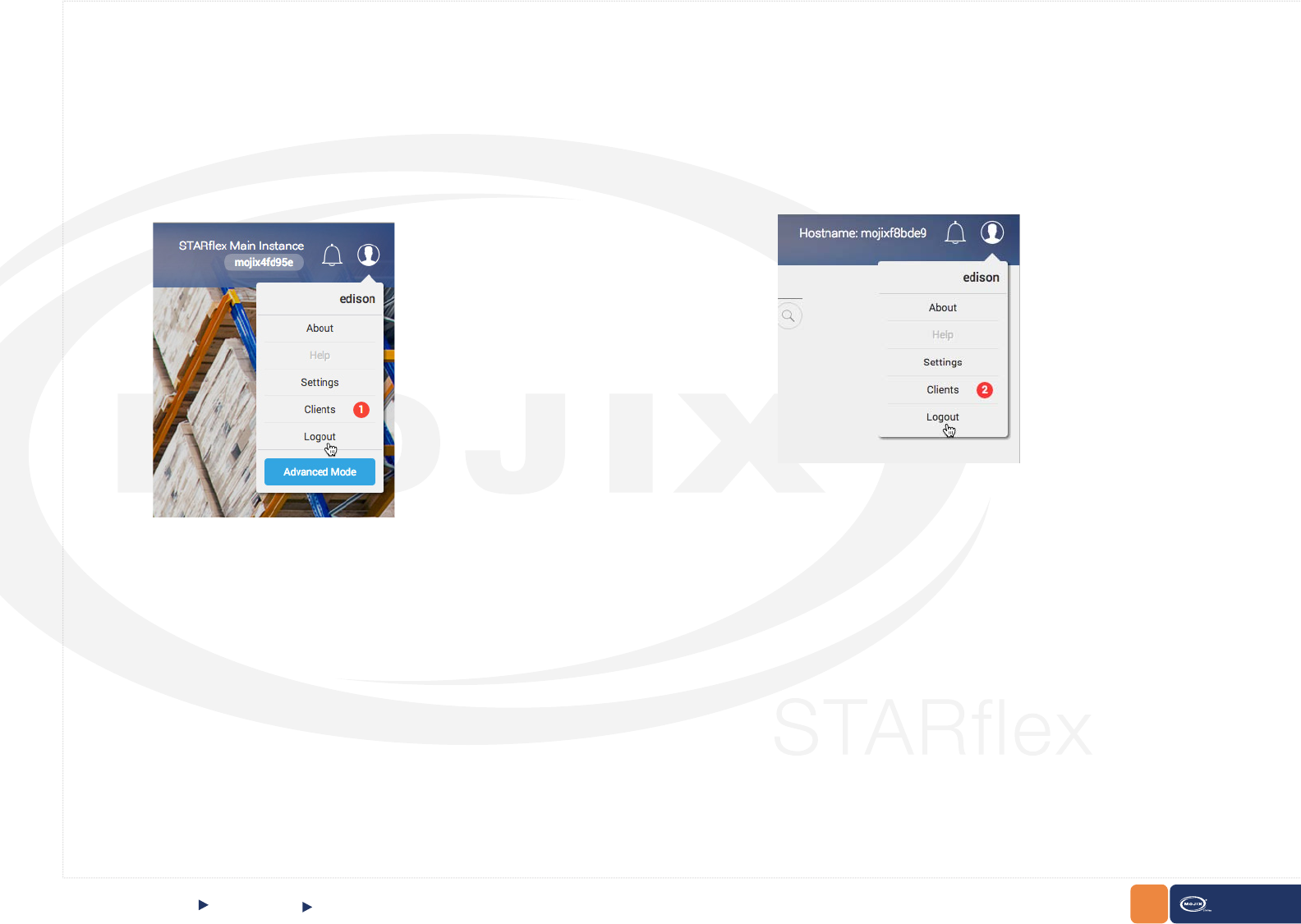
Under the User Icon the following options are available:
These options are detailed below:
CHAPTER II: BASICS QUICK START Logging into STARex
26
CHAPTER II: BASICS STARex MANUAL
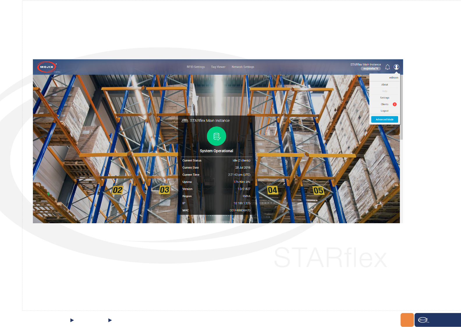
QUICK START About
The “About” section is displayed for user logged on at the top right side of the page, clicking on the “user” icon and then in About.
2.1.5 ABOUT
27
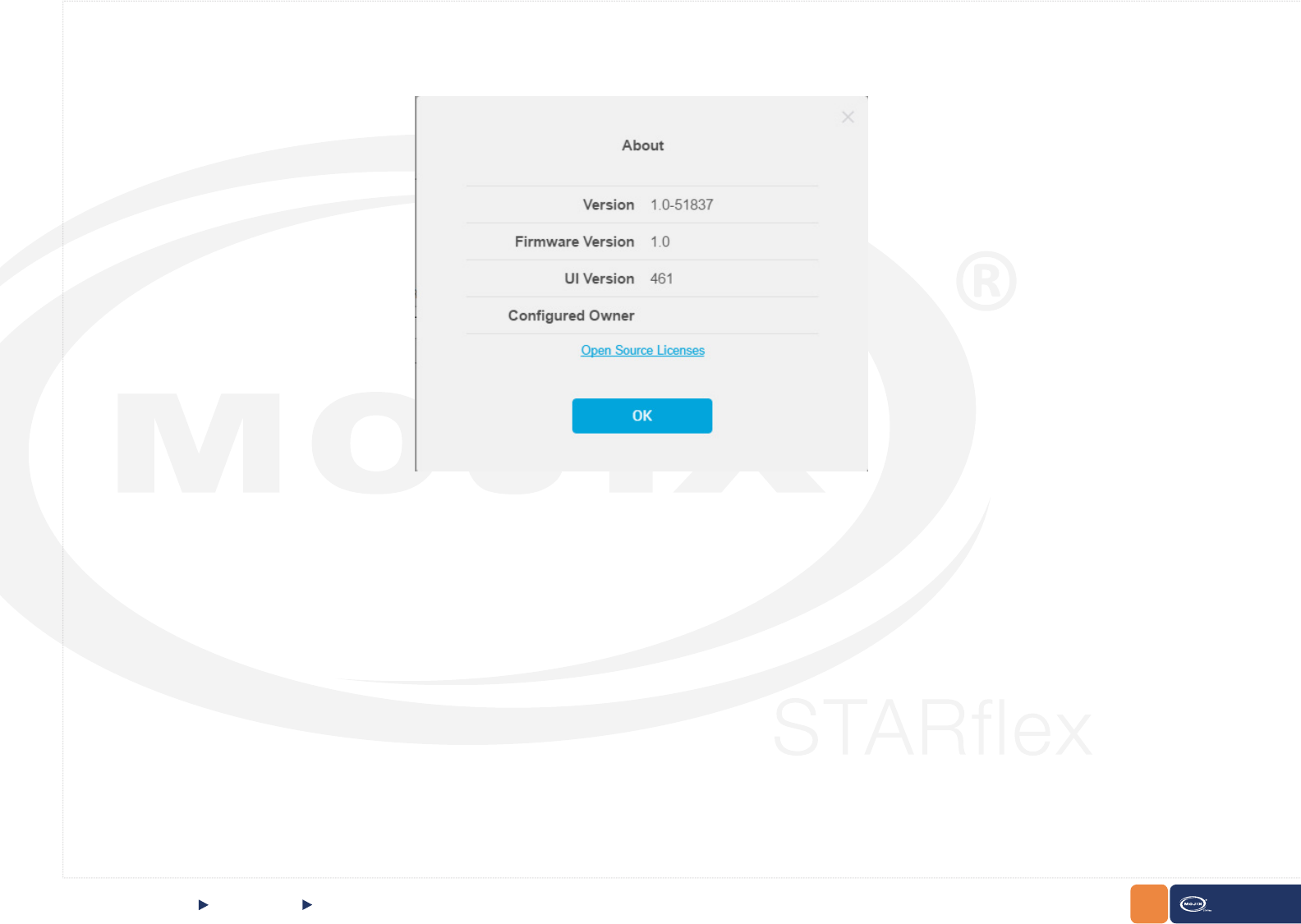
CHAPTER II: BASICS STARex MANUAL
About
This section shows information about the Firmware version, Version, Build Number, UI version and the Congured Owner of the STARex.
Quick Start
28
CHAPTER II: BASICS STARex MANUAL
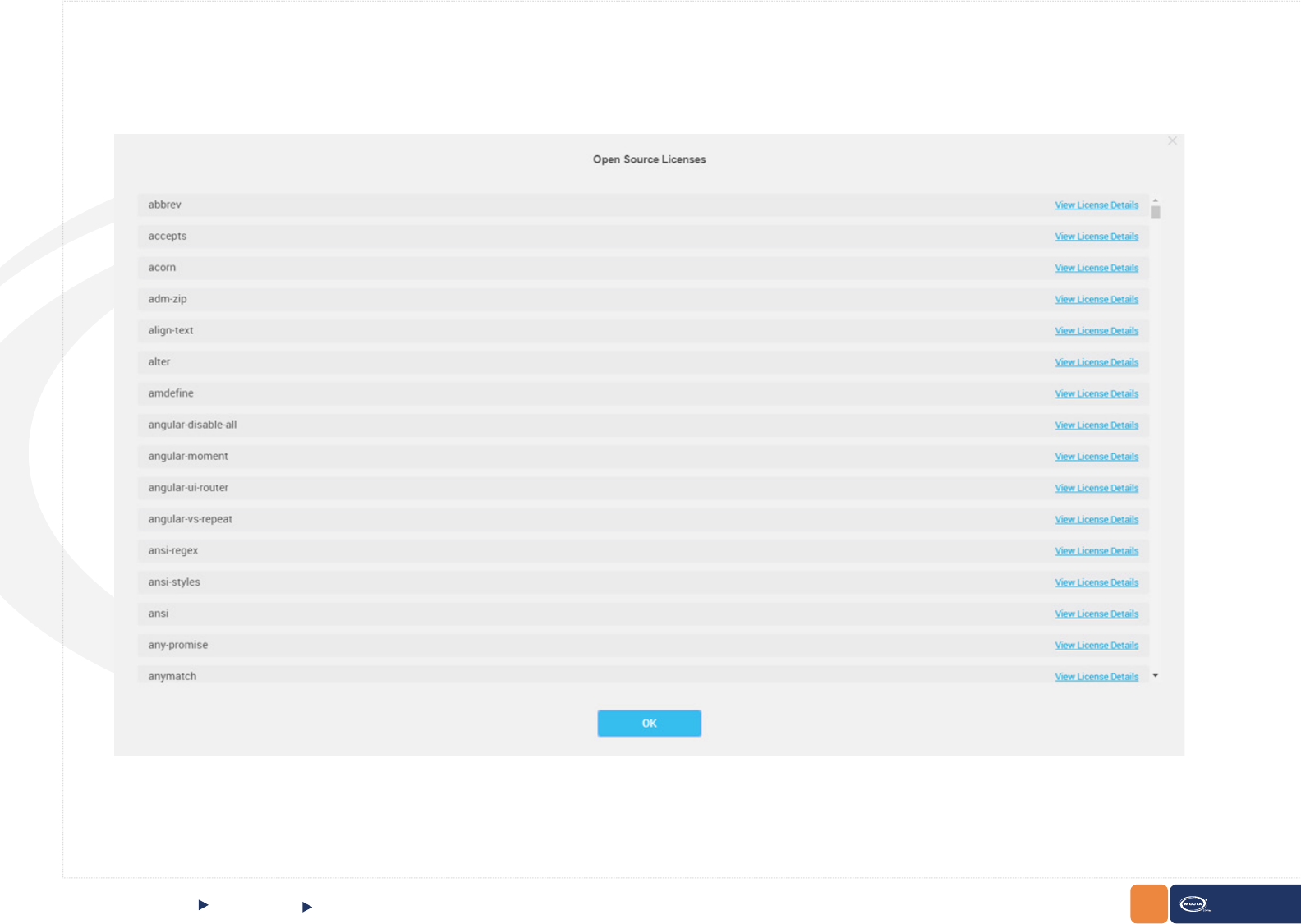
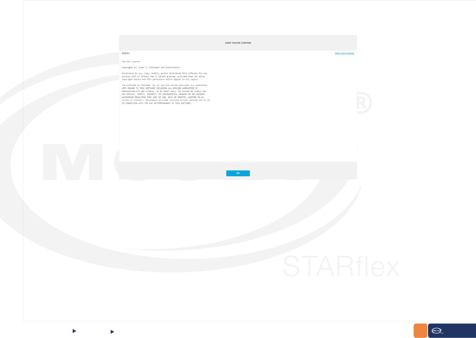
Click on the Open Source Licenses link to get the list of available licenses. View the content of the different licenses used for the STARex by clicking
on the View License Details link:
About
Quick Start
Some of the font licenses includes a Homepage link such as roboto and droid-sans-mono. Click on the Homepage link and it will redirect to the web page
of the font license.
29
CHAPTER II: BASICS STARex MANUAL
In addition, view the content of the different licenses used for the STARex by clicking on the View License Details link:
Click on Hide License Details to hide the information and return to the License main list.
About
Quick Start
30
CHAPTER II: BASICS STARex MANUAL
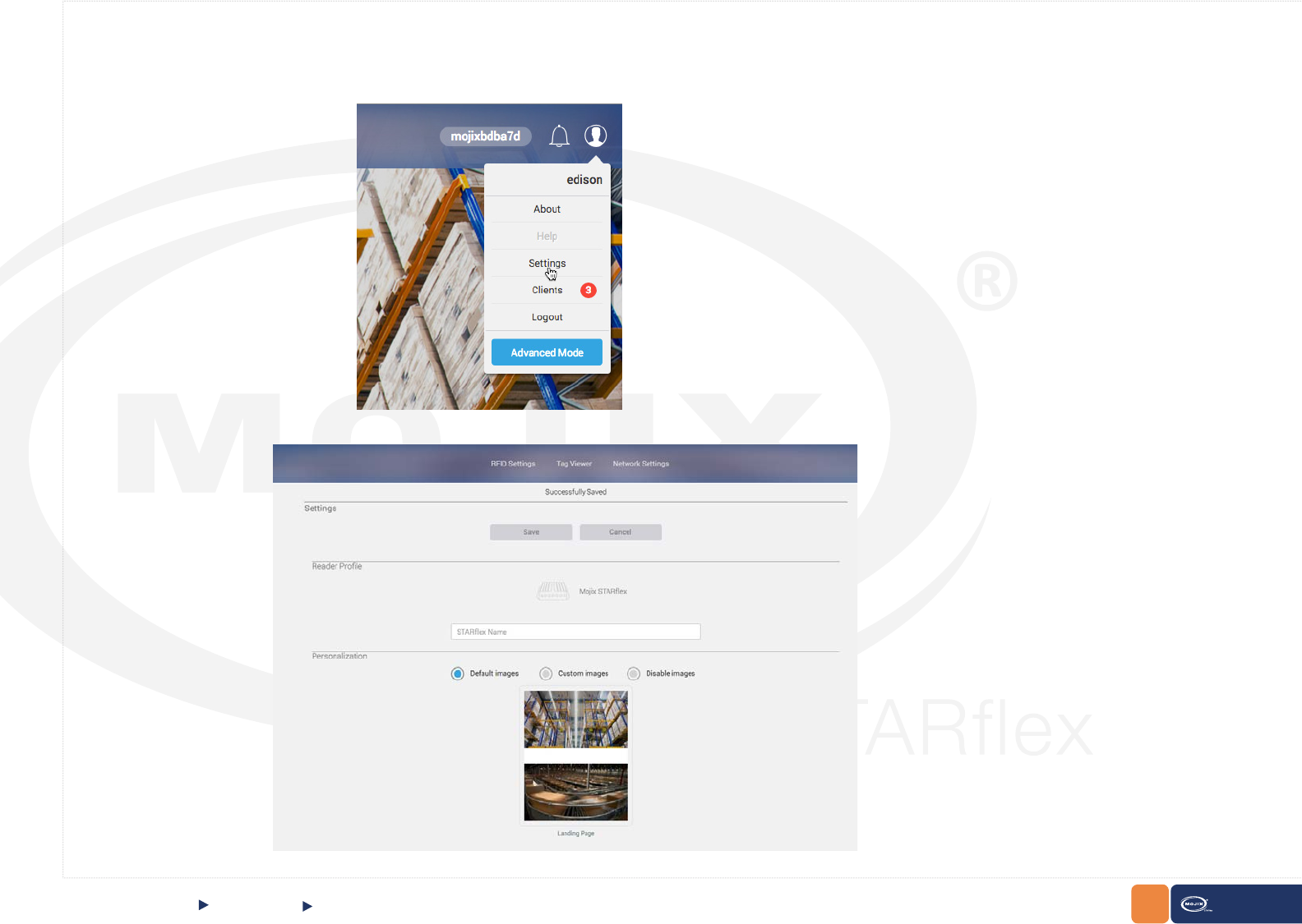
2.1.6 SETTINGS
The “Settings” option provides the possibility to associate a meaningful name to the STARex device and to change the landing page background images.
Settings
Quick Start
Click over the Settings option and the following
conguration will appear:
31
CHAPTER II: BASICS STARex MANUAL
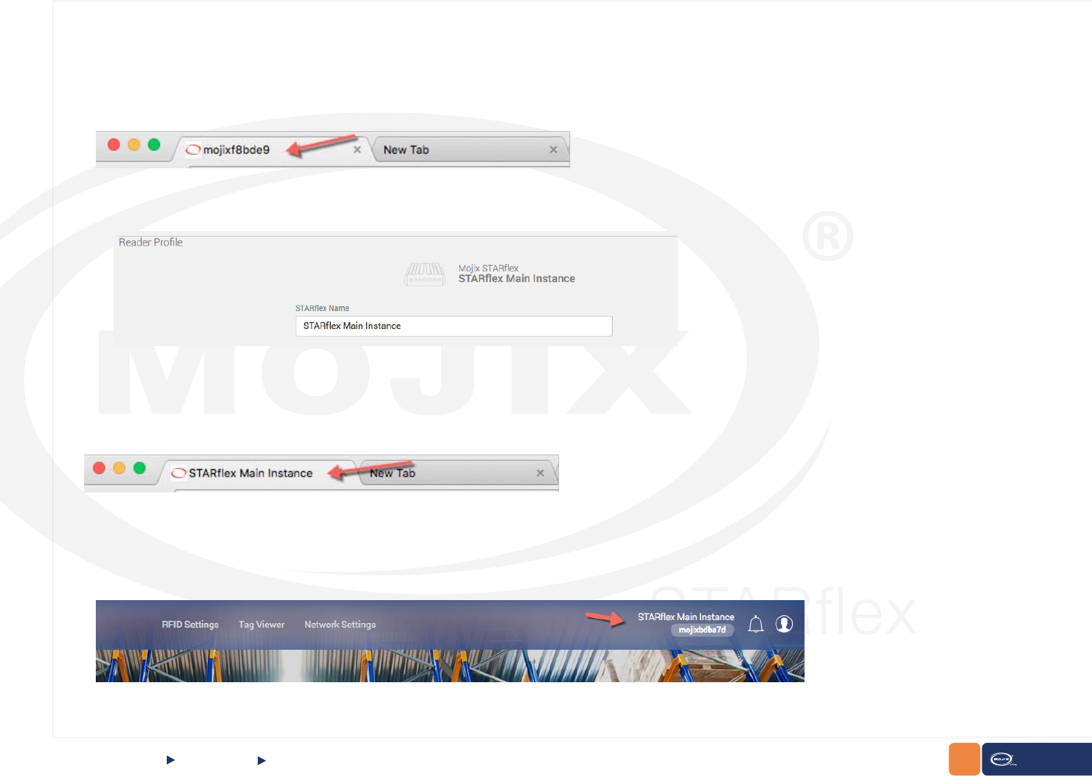
Associate a meaningful name to the STARex device.
Click on the Save button and the label will be changed in the tab browser:
Settings
Quick Start
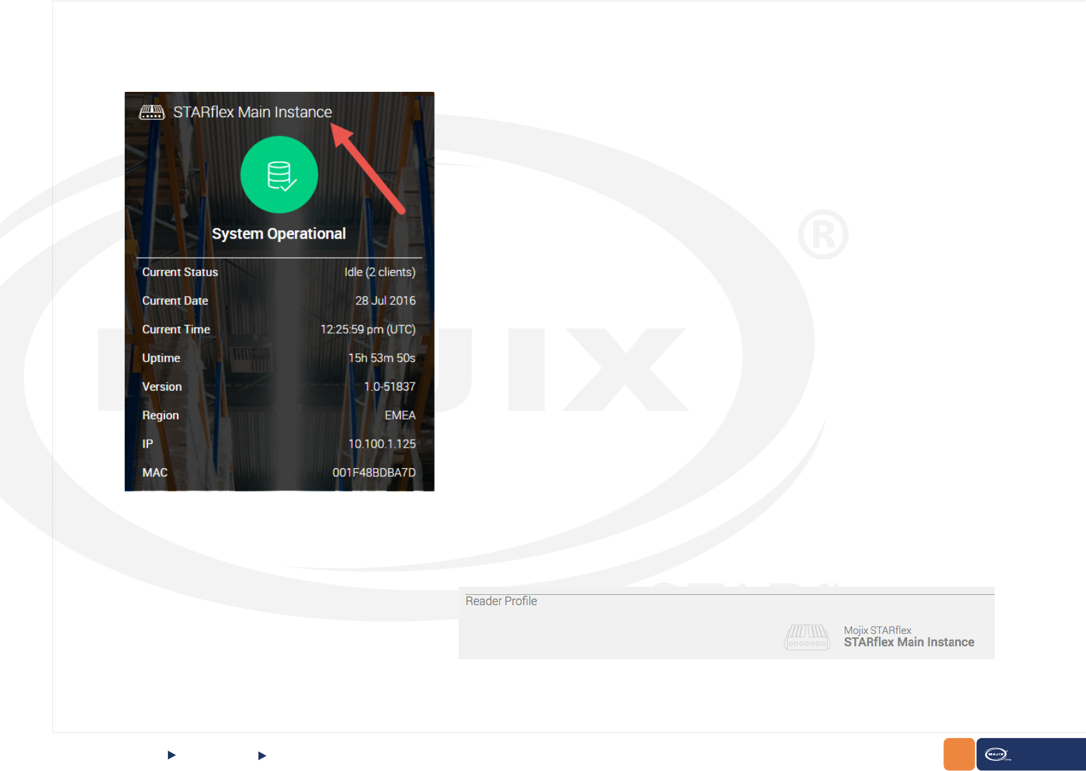
It will also update the label appeared in the following places:
In the landing page above System Operational label:
Reader Prole:
32 STARex MANUAL
CHAPTER II: BASICS
In the landing page above System Operational section:
Settings
Quick Start
Under the Reader Prole Section:
33
CHAPTER II: BASICS STARex MANUAL
Settings
Quick Start
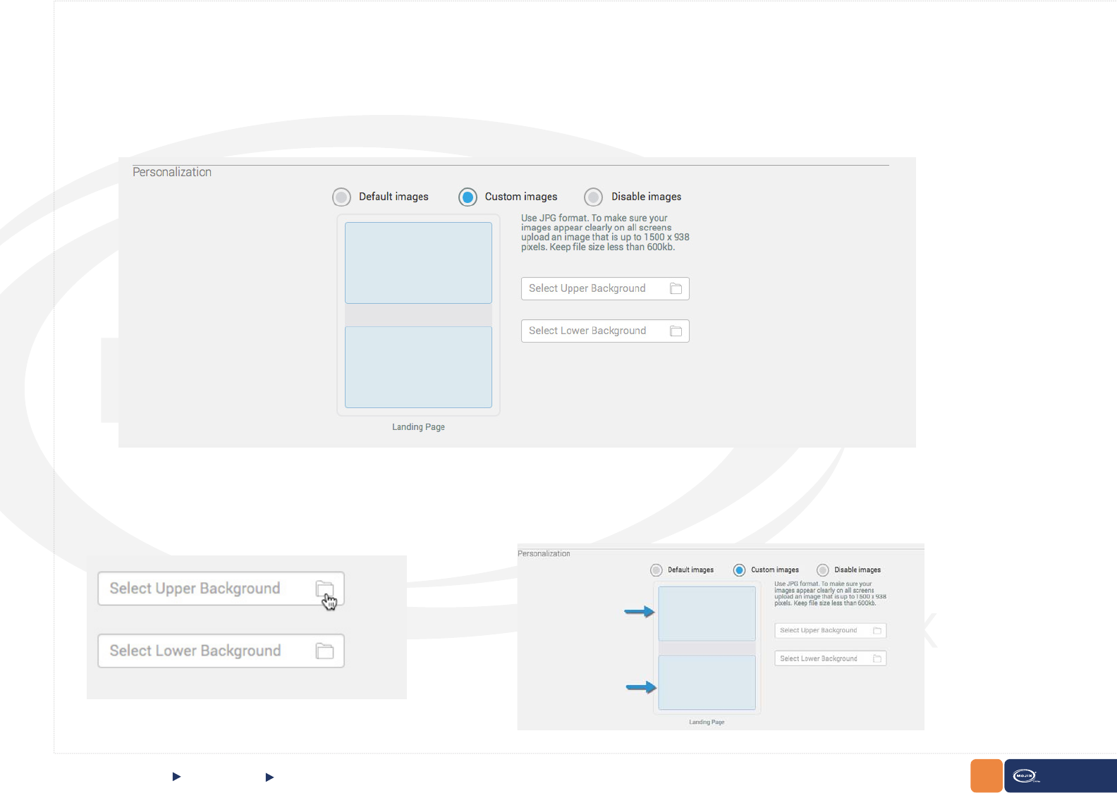
Personalization:
Select the background image the instance will use. The following three options can be selected:
Default images: Select this option to use the default images:
Custom Images: Upload two type of images, one for the upper background and the other one for the lower background. Click on the folder icon or in the
select box to search for images in the local computer:
34
CHAPTER II: BASICS STARex MANUAL
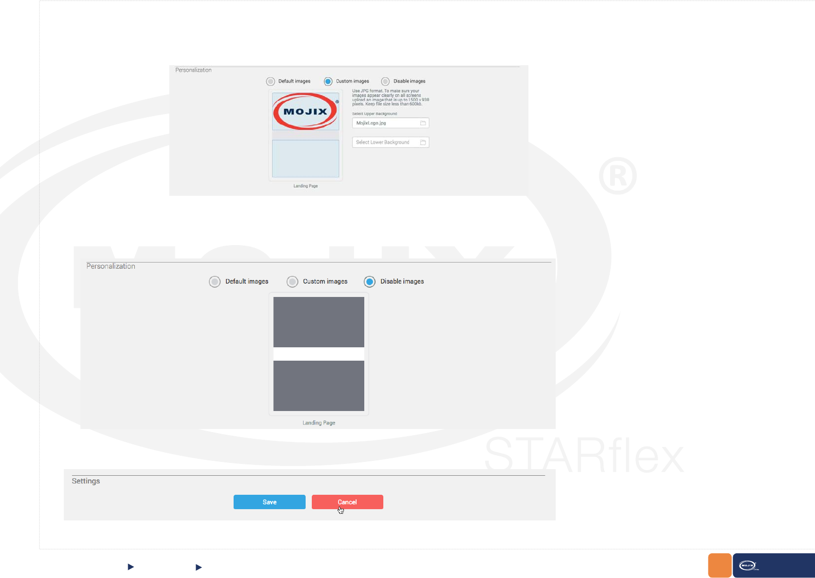
Click on the Save button in order to save changes or click on the Cancel button to discard changes.
Settings
Quick Start
A preview of the image will appear in the upper background area.
Disable images: Select this option if no images are required to be displayed as upper and lower background. A preview of how the background will look like
will display:
35
CHAPTER II: BASICS STARex MANUAL
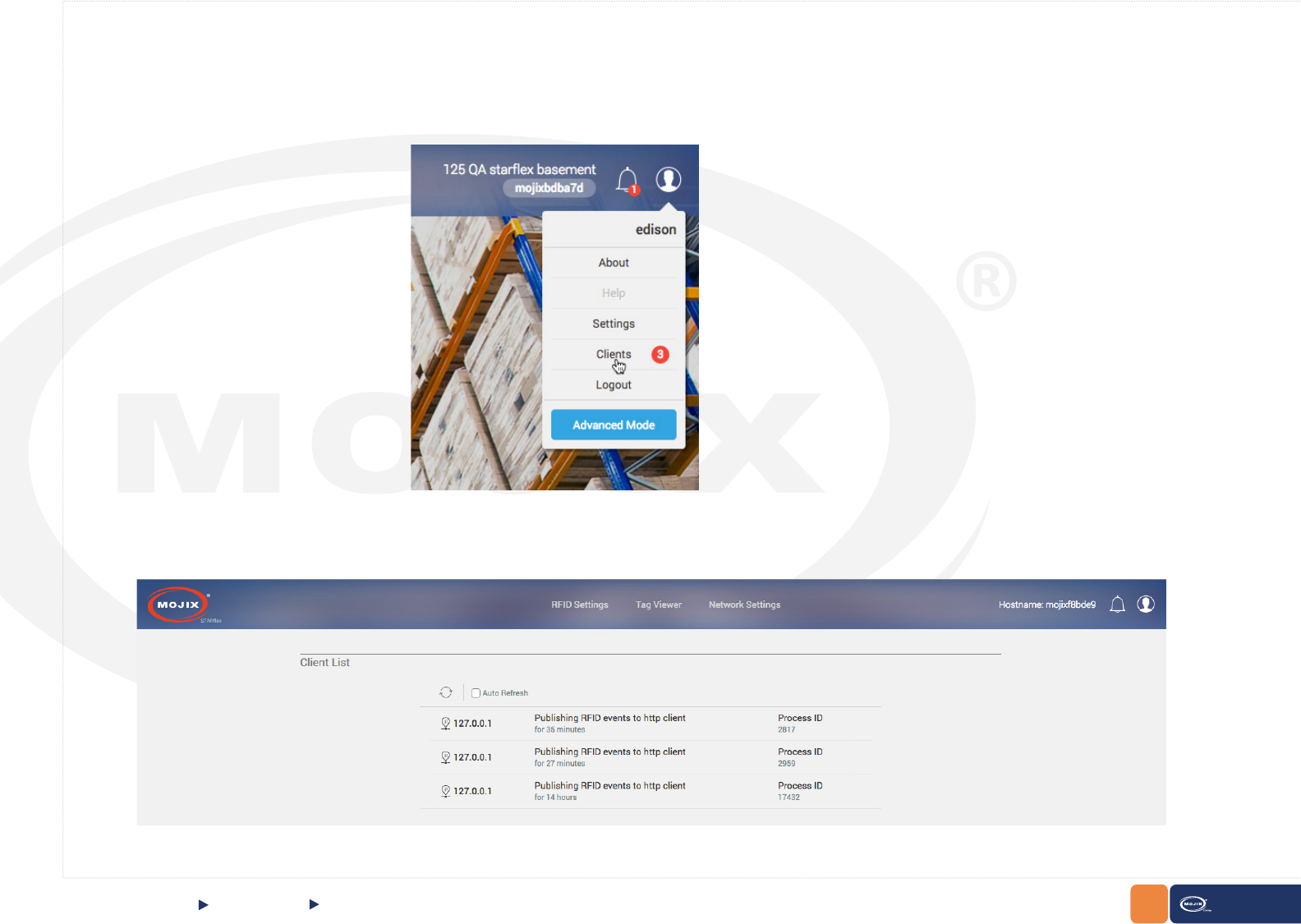
2.1.7 CLIENT LIST
The client list page displays the information of every client that is connected to the STARex. The number of available clients will be displayed inside the
user prole menu:
The client list page displays the information of every client who is connected to the STARex. It includes the IP address, the length of time and the
Process ID of each client. STARex has a maximum number of ve clients (4 http and 1 MQTT).
Client List
Quick Start
36
CHAPTER II: BASICS STARex MANUAL
The number of clients can also be checked in the Landing Page under the
System Operational
section:
Client List
Quick Start
37
CHAPTER II: BASICS STARex MANUAL
2.1.8 LOGGING OUT OF STARFLEX
Logging out of STARex
Quick Start
Logging out allows you to exit the current STARex session. Perform the following procedures to log out of the STARex user interface:
1. Click on the Logout link displayed once the User Icon is clicked on the top right side.
From the Basic Mode: From the Advanced Mode:
38
CHAPTER II: BASICS STARex MANUAL
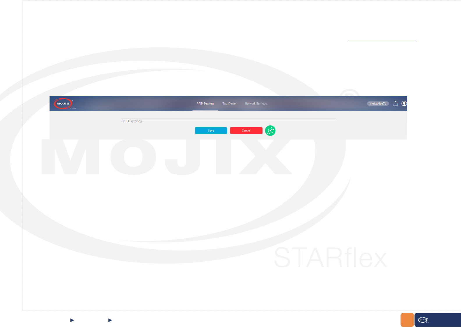
RFID Settings
The RFID settings section allows the user to view and congure different Antennas that are associated to the STARex. These selections include antenna,
port, eNode antennas, receive antenna mode, physical layer settings and patterns. For detailed information please refer to Chapter III RFID Settings.
2.1.9 BASIC MODE
QUICK START Basic Mode
39
CHAPTER II: BASICS STARex MANUAL
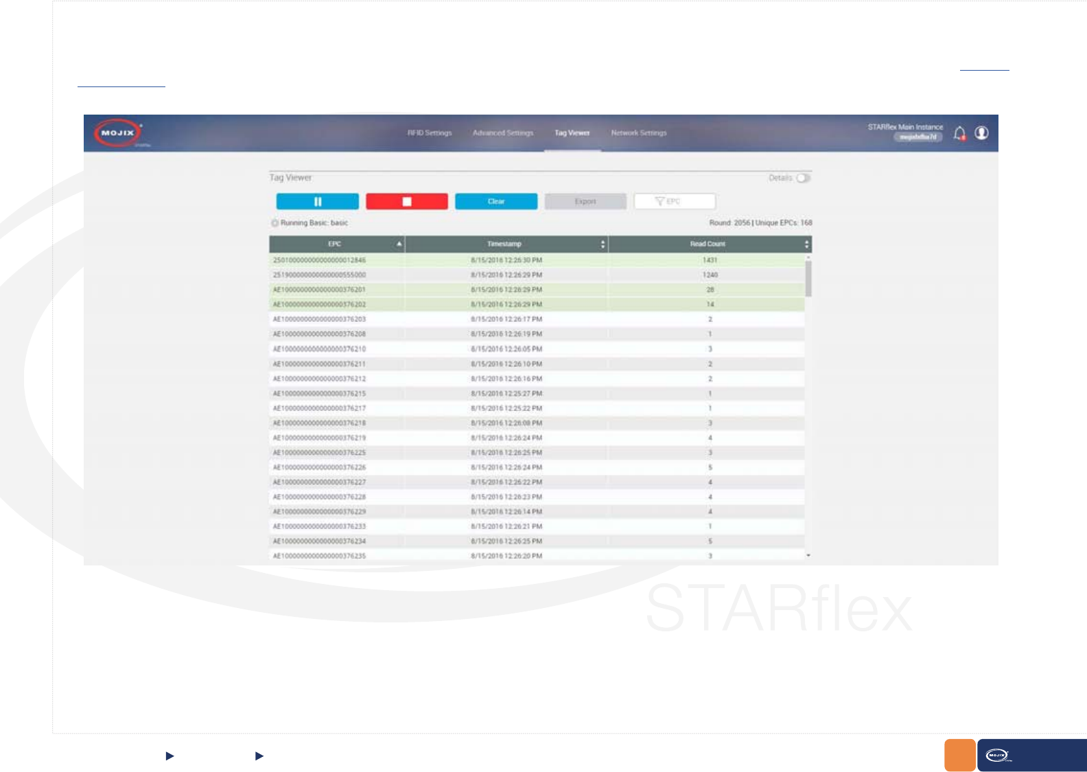
QUICK START Tag Viewer
Tag Viewer
The tag viewer section allows the user to quickly select and turn on antennas in order to nd and read tags, displaying all the found tags in a list. In addition,
it is possible to lter while live reading the EPCs, TxID (transmit antenna) and export the list in a CSV le. For detailed information please refer to Chapter
IV Tag Viewer.
40 STARex MANUAL
CHAPTER II: BASICS QUICK START Basic Mode
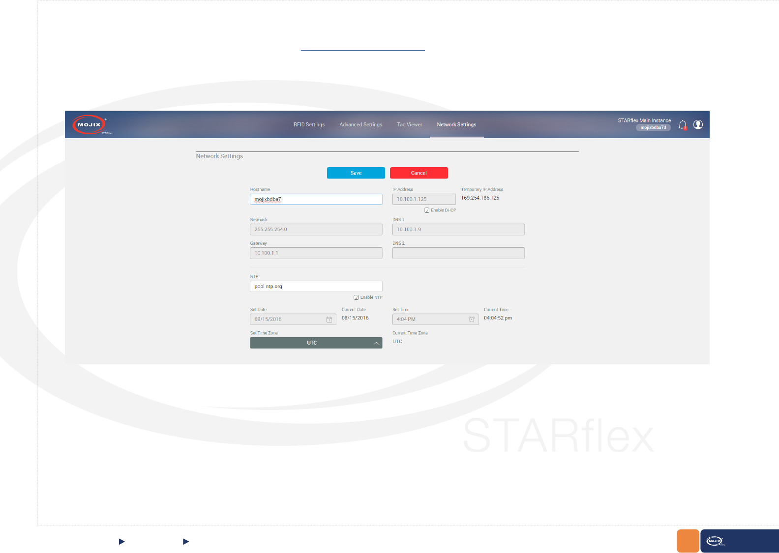
Network Settings
The network settings section describes a set of elds to congure the network that the STARex will use. In this menu the DHCP values can be assigned
to the STARex. For detailed information please refer to Chapter V Network Settings.
41
CHAPTER II: BASICS STARex MANUAL
2.1.10 ADVANCED MODE
QUICK START Advanced Mode
Inside the Advance Mode, the following tabs are available:
For detailed information of each one of the tabs, refer to Chapter III - RFID Settings, Chapter IV - Tag Viewer and Chapter V - Network Settings
Access to the Advanced Mode by selecting the option, then click on the Advanced Mode button:
Introduce the password to have access to the Advanced Mode:
42
CHAPTER II: BASICS STARex MANUAL
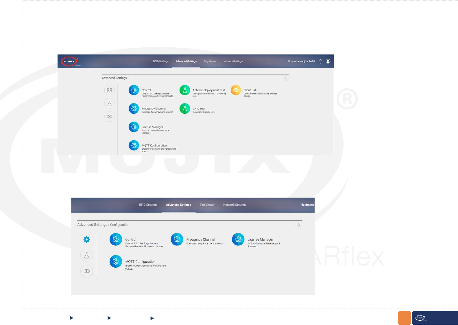
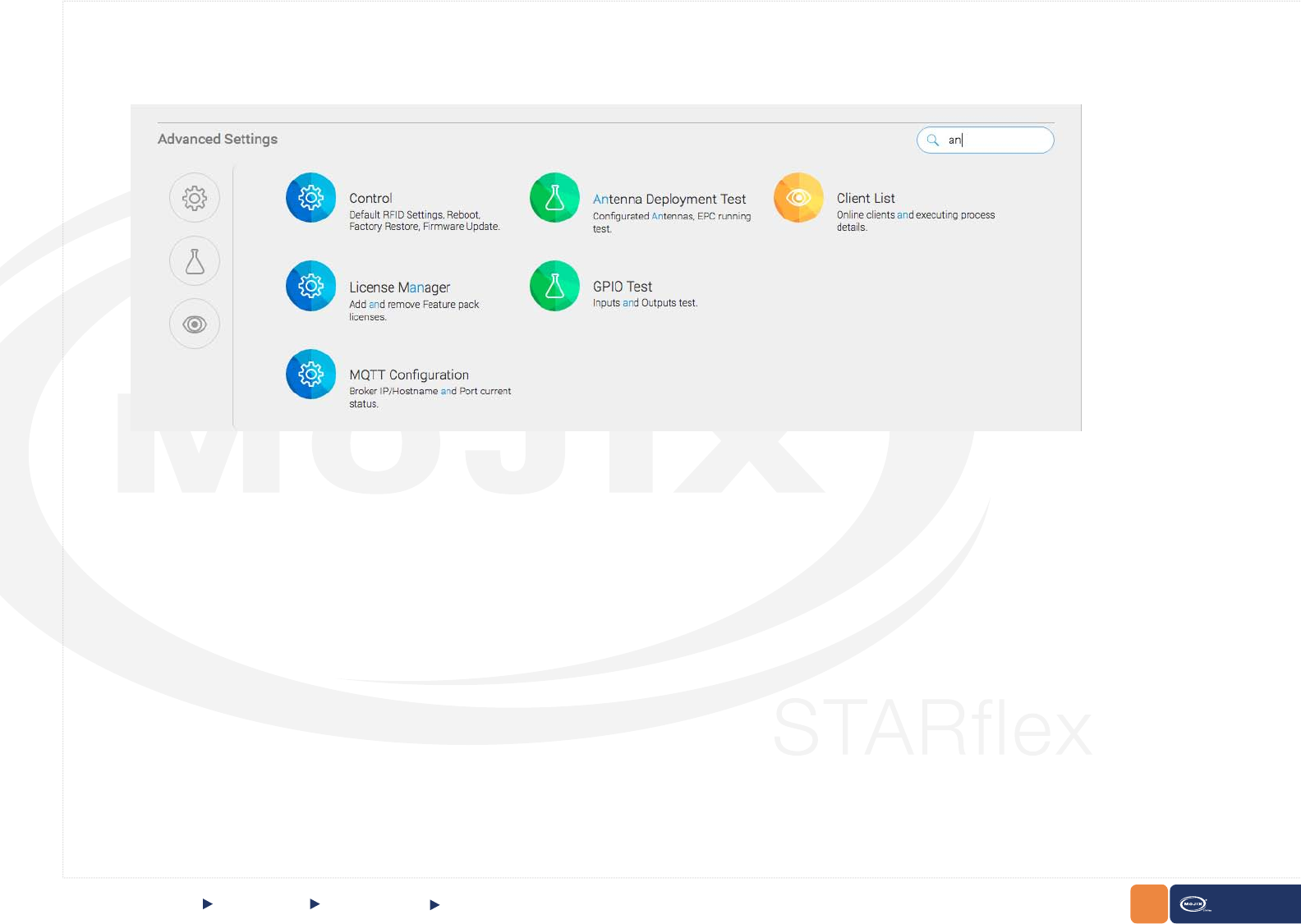
The Advanced Settings tab includes the following conguration options:
At the right side of the screen options are grouped by color depending on their functionality:
While at the left side, 3 lters for each one of the groups are displayed:
Conguration:
QUICK START Advanced Mode Advanced Settings, Conguration
Advanced Settings
43 STARex MANUAL
CHAPTER II: BASICS
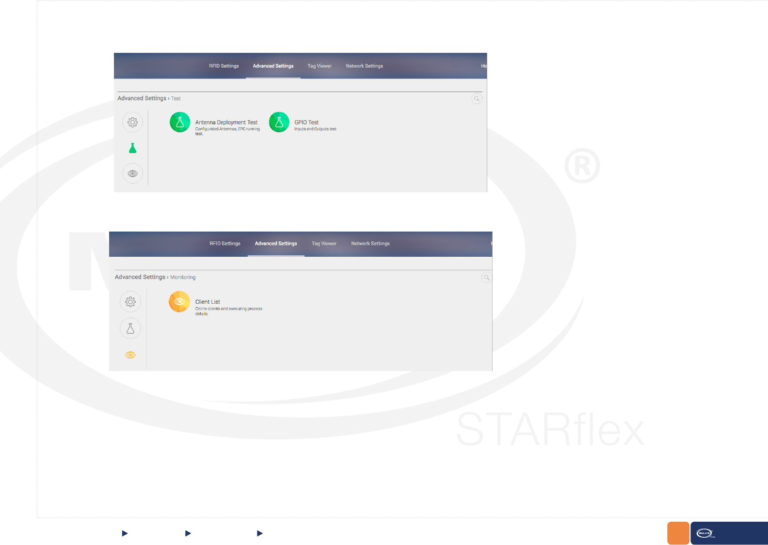
Test:
Monitoring:
QUICK START Advanced Mode Test, Monitoring
44
CHAPTER II: BASICS STARex MANUAL
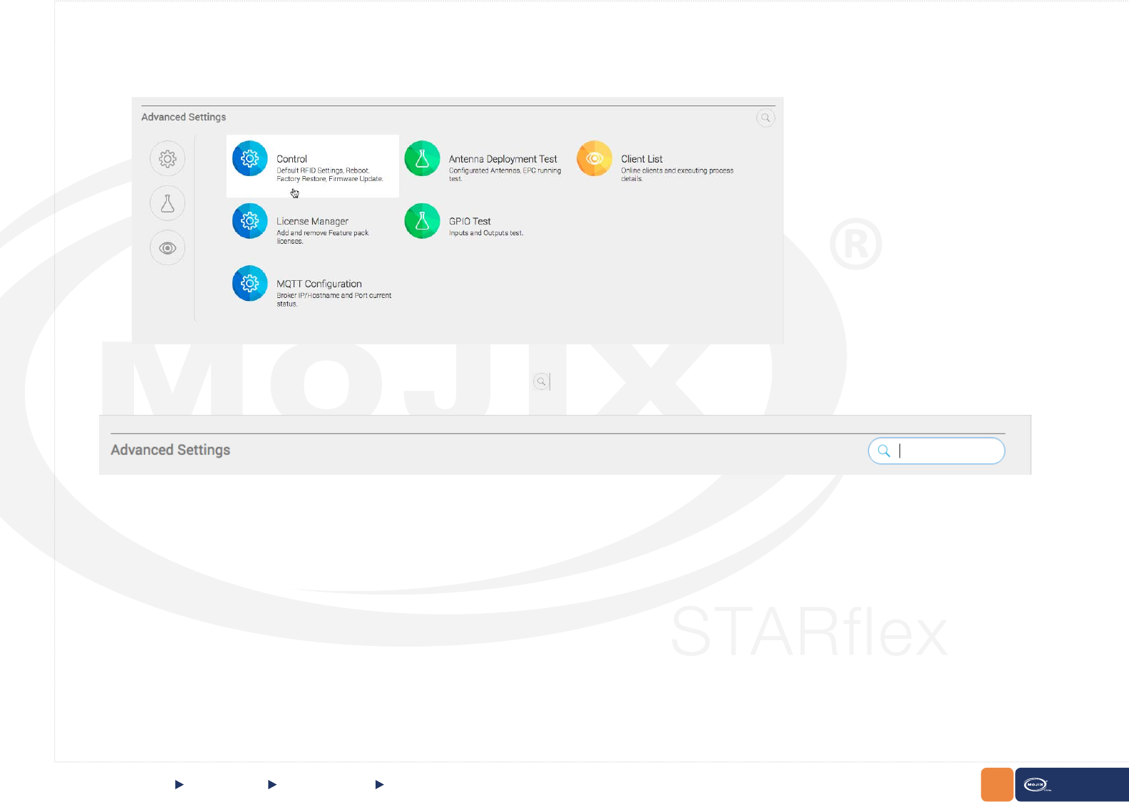
QUICK START Advanced Mode
- Mouse over to highlight the option:
- Search for specic options by using the search option. Click on the to expand the search bar:
Test, Monitoring
45
CHAPTER II: BASICS STARex MANUAL
Introduce some text inside the text eld and it will automatically highlight the text found among the different options:
If no text is introduced in the text eld, by default all options will be listed.
QUICK START Advanced Mode Test, Monitoring
46
CHAPTER II: BASICS STARex MANUAL
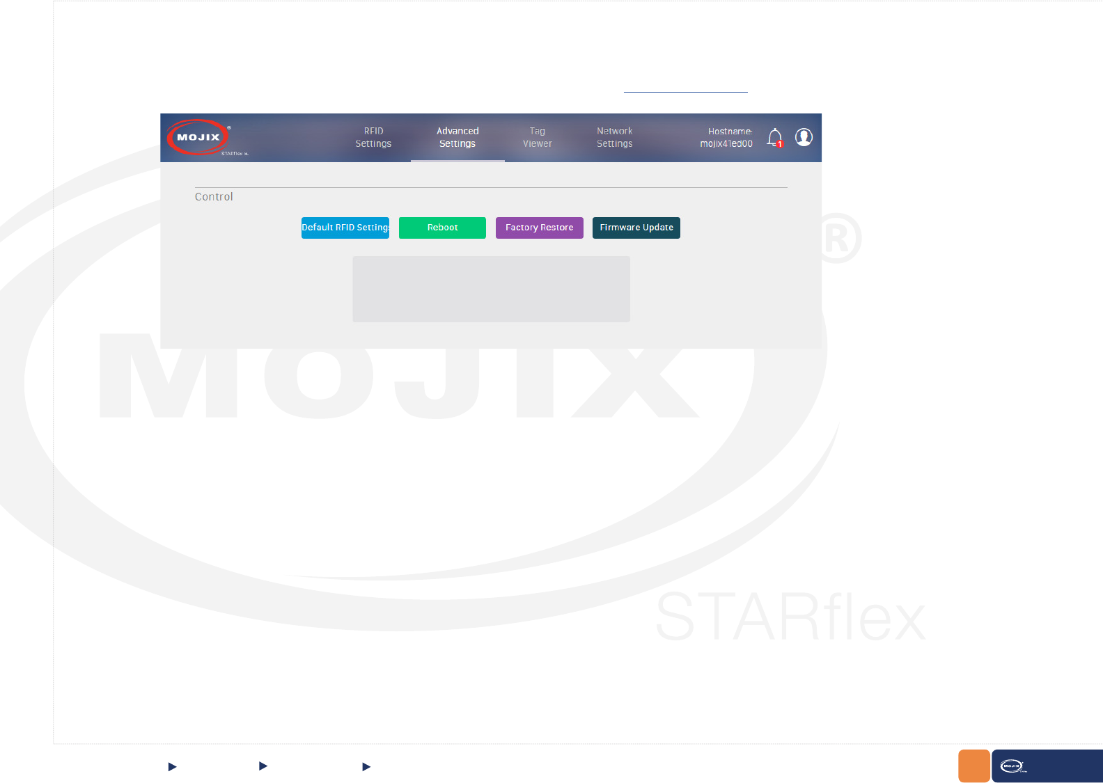
Control
The Control section describes four available options, Default RFID Settings (reset all RFID settings), Reboot, Factory Restore (restore to the
original conguration) and Firmware Update. For detailed information please refer to Chapter VI - Control.
QUICK START Advanced Mode Control
47
CHAPTER II: BASICS STARex MANUAL
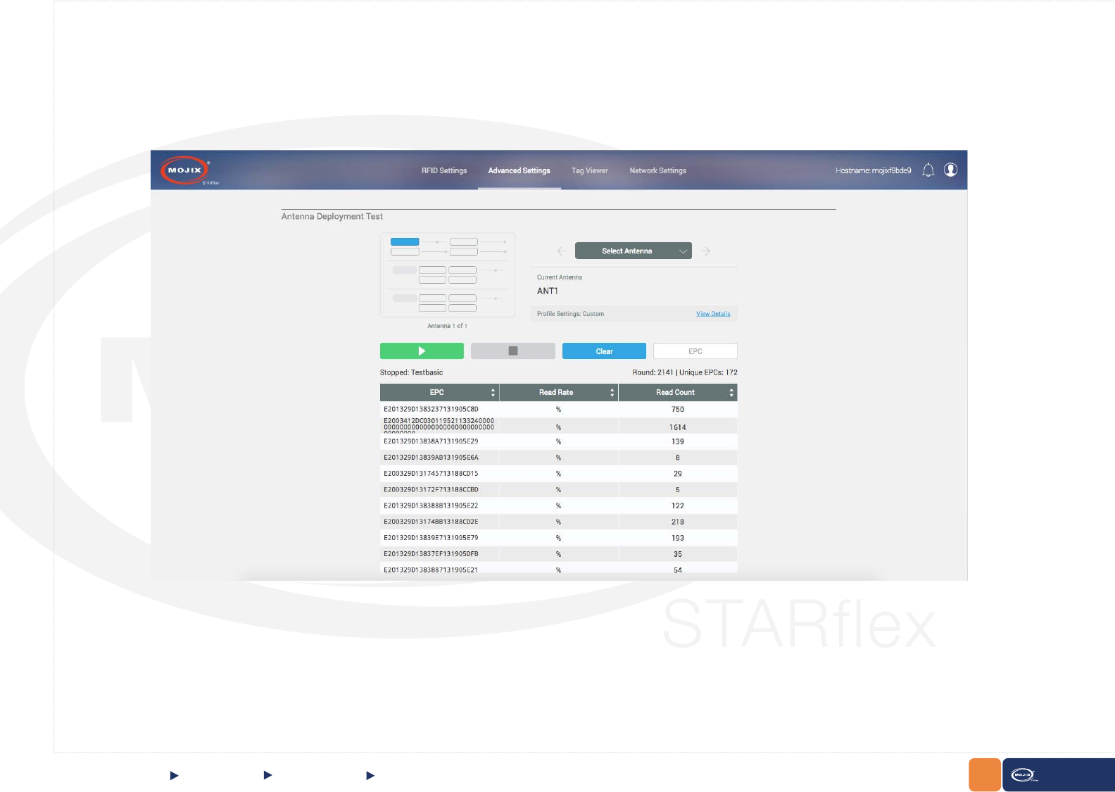
Antenna Test
The “Antenna Deployment Test” page allows the user to step through the congured antennas in the basic settings page (refer to Chapter III - RFID Settings)
in order to test them one by one and make sure they each can read tags. This process ensures proper continuity of cables and antennas. For detailed
information please refer to Chapter VI - Antenna Test.
QUICK START Advanced Mode Antenna Test
48
CHAPTER II: BASICS STARex MANUAL
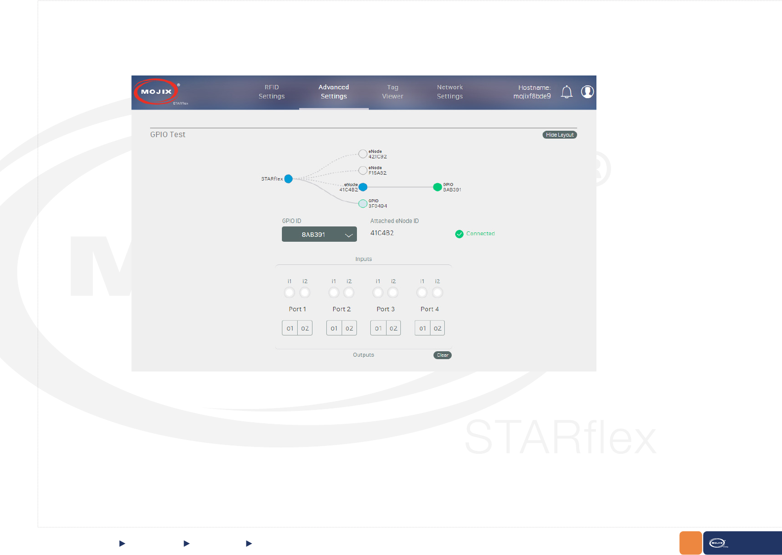
QUICK START
GPIO Test
The “GPIO Test” page allows the user to validate the state of connected input devices and to test output devices by triggering the respective output through
the interface. For detailed information please refer to Chapter VI - GPIO Test.
Advanced Mode GPIO Test
49
CHAPTER II: BASICS STARex MANUAL
QUICK START
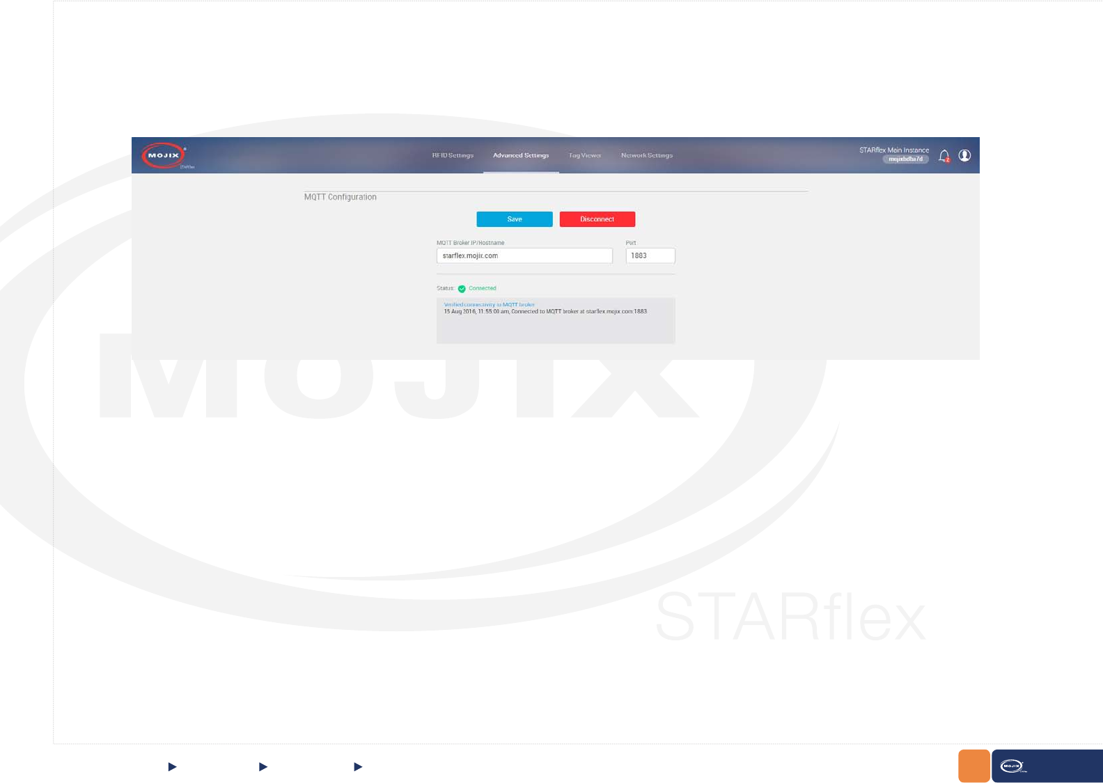
MQTT Conguration
The “MQTT Conguration” page allows the user to set up the hostname/IP address, port to connect and test to the MQTT broker. For detailed information
please refer to Chapter VI - MQTT Conguration.
Advanced Mode MQTT Conguration
50
CHAPTER II: BASICS STARex MANUAL
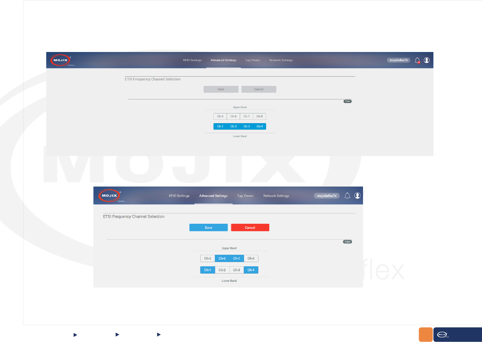
Frequency Channel
STARex automatically detects its “Jurisdiction” on boot up and disables this control for all models except EU models. The “Jurisdiction/model” of STARex
can not be changed in the eld. Only low band channels are all selected by default.
QUICK START
If the conguration is changed, the Save and Cancel button will be enabled:
Advanced Mode Frequency Channel