MTD 13AP625K730 User Manual TRACTOR Manuals And Guides 1109172L
User Manual: MTD 13AP625K730 13AP625K730 MTD TRACTOR - Manuals and Guides View the owners manual for your MTD TRACTOR #13AP625K730. Home:Lawn & Garden Parts:MTD Parts:MTD TRACTOR Manual
Open the PDF directly: View PDF ![]() .
.
Page Count: 36

Safety • Assembly • Operation • Tips & Techniques • Maintenance • Troubleshooting • Parts Lists • Warranty
AOAL
)
Hydrostatic Lawn Tractor- Model Series 620
iMPORTANT
READ SAFETY RULES AND iNSTRUCTiONS CAREFULLY BEFORE OPERATION
Warning: Thisunit is equippedwithan internalcombustionengineandshouldnot beusedon or nearany uniiprovedforest-covered,brush-
coveredor grass-coveredlandunlesstheengine'sexhaustsystemis equippedwitha sparkarrestermeetingapplicablelocalor statelaws(if any).
If a sparkarresteris used,it shouldbemaintainedineffectiveworkingorderby the operator.In theStateof Californiathe aboveis requiredbylaw
(Section4442of the CaliforniaPublicResourcesCode).Otherstatesmayhavesimilarlaws.Federallawsapplyonfederallands.A sparkarrester
for the muffleris availablethroughyour nearestengineauthorizedservicedealeror contactthe servicedepartment,RO.Box361131Cleveland,
Ohio44136-0019.
PRINTEDIN U.S.A MTD LLC, P.O. BOX 361131 CLEVELAND, OHIO 44136-0019 FORMNO.769-02964
12/13/2006

This Operator's Manual is an important part of your new lawn tractor, it will help you assemble,
prepare, and maintain the unit for best performance. Please read and understand what it says.
Table of Contents
Slope Gauge ........................................................ 3
Safe Operation Practices ................................... 4
Setting UpYour Lawn Tractor ............................ 8
Operating Your Lawn Tractor ........................... 12
Adjusting Your Lawn Tractor ............................ 20
Maintaining Your Lawn Tractor ........................ 22
Off-Season Storage /Attachments ................. 28
Safety Labels .................................................... 29
Troubleshooting ................................................ 30
Replacement Parts ........................................... 32
Finding and Recording Model Number
BEFOREASSEMBLINGYOUR NEW EQUIPMENT,please
locatethe model plateon the equipmentandcopy the
information to the sample model plate provided to the right.
Youcan locatethe model plate by looking under the seat. This
informationwill be necessary to use the manufacturer'sweb
site, to obtain assistancefrom the Customer Support Depart-
ment, or when contacting an authorizedservice dealer.
Model Number
www.mtdproducts,com
Serial Number
MTD LLC
P.O= BOX 361131
CLEVELAND, OH 44136
330-220-4683
800-800-7310
Customer Support
Please do NOTreturn the unit to the retailer from which it was
purchased, without first contacting Customer Support.
Ifyou have difficulty assemblingthis product or have any questions regardingthe controls, operation,or maintenanceof this
unit, you can seek help from the experts.Choose from the options below:
1. Visit www.mtdproducts.com.
2. Phonea Customer Support Representative at 1 (800) 800-7310.
3. The engine manufacturer is responsiblefor all engine-relatedissueswith regardsto performance, power-rating,specifica-
tions, warranty and service. Please refer to the engine manufacturer'sOwner's/Operator's Manual, packed separatelywith
your unit, for moreinformation.
2

>:.
G.)
o9
(13
(13
O
O
C
::>.,
E
c_
O
G.)
o6
_-- (13
co .oo
G.) o9
o -_
O9 C:_
G.) O9
C C
_ o
(13
-_ o_
OC
(13
c_
0
o3
0
C
co 0
_ a
Sight and h01dthis level with a vertical tree..,
m_,_ or a corner of a building...
I
I__ or a fence post
I
i i
do;
-- fine (repros
I _ _ er_ts a 15o
15°
_0

Operation
WARNING
This symbol points
out importantsafety
instructionswhich, if
notfollowed, could
i endangerthe personal
safetyand/or property
ofyourself and others.
I Readand follow all
i instructions inthis man-
i ual before attempting to
i operatethis machine.
Failureto complywith
these instructionsmay
result in personal injury.
i Whenyou see this
symbol.
i HEED ITS WARNING
Your
i Responsibility
Restrictthe use
of this power machine
I to persons who read,
understand
and follow the warnings
and instructions
inthis manual
WARNING: Engine Exhaust,some of its constituents, andcertain vehicle compo-
nentscontain or emit chemicals knownto Stateof Californiato cause cancer and
birth defects or other reproductiveharm.
DANGER: This machinewas built to be operated according to the rulesfor safe operation in this
manual.As with any type of power equipment,carelessness or error on the part of the operator can
result in serious injury.This machine is capable of amputating hands andfeet andthrowing objects.
Failureto observethe followingsafety instructions could result in serious injury or death.
Children
1. Tragicaccidentscanoccurif the operatoris not
alertto the presenceof children.Childrenareoften
attractedto themachineandthe mowingactivity.
Theydo not understandthe dangers.Neverassume
thatchildrenwill remainwhereyou lastsawthem.
a. Keepchildrenout of the mowingareaandin
watchfulcare of a responsibleadultother than
the operator.
b. Bealert andturnmachineoff ifa childenters
the area.
c. Beforeandwhile backing,lookbehindand
downfor smallchildren.
d. Nevercarrychildren,evenwiththe blade(s)
shutoff.Theymayfalloffandbeseriously
injuredorinterferewithsafemachineoperation.
e. Useextremecarewhenapproachingblind
corners,doorways,shrubs,treesorother
objectsthat mayblockyourvisionof achild
whomayrunintothe machine.
f. To avoid back-over accidents, always
disengagethe cuttingblade(s) before
shiftinginto Reverse.If equipped,the
"Reverse CautionMode"shouldnotbe
used whenchildrenor others are around.
g. Keepchildrenawayfromhotor running
engines.Theycan sufferburnsfroma hot
muffler.
h. Removekeywhenmachineis unattendedto
preventunauthorizedoperation.
2. Neverallowchildrenunder14yearsoldto operate
the machine.Children14yearsoldandovershould
readand understandthe operationinstructionsand
safetyrulesinthis manualandshouldbetrainedand
supervisedbya parent.
Operation
Safe Handlingof Gasoline:
1. Toavoid personalinjuryor propertydamageuse
extremecare in handlinggasoline.Gasolineis
extremely flammableand the vapors areexplo-
sive. Seriouspersonalinjurycan occurwhengasoline
isspilledonyourselfor yourclotheswhichcan ignite.
Washyourskinandchangeclothesimmediately.
a. Useonlyanapprovedgasolinecontainer.
b. Neverfill containersinsideavehicleor ona
truckor trailerbedwitha plasticliner.Always
placecontainersonthe groundawayfrom
yourvehiclebeforefilling.
c. Whenpractical,removegas-powered
equipmentfromthe truckor trailerand refuelit
onthe ground.Ifthis isnotpossible,then
refuelsuchequipmenton a trailerwitha
portablecontainer,ratherthan froma gasoline
dispensernozzle.
d. Keepthe nozzlein contactwiththe rimof
the fueltankor containeropeningat all
timesuntilfuelingiscomplete.Donot usea
nozzlelock-opendevice.
e. Extinguishallcigarettes,cigars,pipesand
othersourcesof ignition.
f. Neverfuel machineindoors.
g. Neverremovegas cap oraddfuel whilethe
engineishot or running.Allowengineto cool
at leasttwominutesbeforerefueling.
h. Neveroverfill fuel tank.Fill tankto nomore
than1/2inchbelowbottomof filler neckto
allowspacefor fuel expansion.
i. Replacegasolinecapandtightensecurely.
j. If gasolineis spilled,wipe it off theengine
andequipment.Moveunit to anotherarea.
Wait5 minutesbeforestartingtheengine.
k. Toreducefirehazards,keepmachinefreeof
grass,leaves,orotherdebris build-up.Clean
upoil orfuel spillageand removeanyfuel
soakeddebris.
I. Neverstorethe machineorfuel container
insidewherethere is anopenflame,spark
orpilot lightas on a waterheater,space
heater,furnace,clothesdryerorother gas
appliances.
m. Allowa machineto cool at leastfiveminutes
beforestoring.
4

GeneralOperation:
1. Read,understand,andfollowall instructionsonthe
machineandin the manual(s)beforeattemptingto
assembleandoperate.Keepthismanualina safe
placefor futureandregularreferenceandfor ordering
replacementparts.
2. Befamiliarwith allcontrolsandtheir properoperation.
Knowhow to stopthe machineanddisengagethem
quickly.
3, Neverallowchildrenunder14yearsold to operate
this machine.Children14yearsoldandovershould
readandunderstandthe operationinstructionsand
safetyrulesinthis manualandshouldbetrainedand
supervisedby a parent.
4. Neverallowadultsto operatethis machinewithout
properinstruction.
5. To helpavoidbladecontactora thrownobjectinjury,
keep bystanders,helpers,childrenand petsat least
75feet fromthe machinewhileit is inoperation.Stop
machineif anyoneentersthearea.
6. Thoroughlyinspecttheareawheretheequipmentis to
be used.Removeall stones,sticks,wire,bones,toys,
andotherforeignobjectswhichcouldbe pickedup
andthrownbythe blade(s).Thrownobjectscancause
seriouspersonalinjury.
7. Planyourmowingpatternto avoiddischargeof
materialtowardroads,sidewalks,bystandersandthe
like.Also,avoiddischargingmaterialagainstawall or
obstructionwhichmaycausedischargedmaterialto
ricochetbacktowardthe operator.
8. Alwayswear safetyglassesor safetygogglesduring
operationandwhile performingan adjustmentor
repairto protectyoureyes.Thrownobjectswhich
ricochetcancauseseriousinjuryto the eyes.
9. Wearsturdy,rough-soledworkshoesandclose-fitting
slacksandshirts.Loosefittingclothesandjewelry
can becaughtinmovableparts.Neveroperatethis
machinein barefeetor sandals.
10.Beawareof the mowerandattachmentdischarge
directionanddo not pointit at anyone.Donot operate
the mowerwithoutthe dischargecoverorentiregrass
catcherin itsproperplace.
11.Donot put handsor feetnearrotatingpartsor under
the cuttingdeck. Contactwiththe blade(s)can
amputatehandsandfeet.
12.A missingor damageddischargecovercan cause
bladecontactorthrownobjectinjuries.
13.Stop the blade(s)whencrossinggraveldrives,walks,
or roadsandwhilenot cuttinggrass.
14.Watchfor trafficwhenoperatingnearor crossing
roadways.Thismachineis not intendedfor useon
anypublic roadway.
15.Do notoperatethe machinewhileunderthe influ-
enceof alcoholordrugs.
16.Mowonly in daylightor goodartificiallight.
17.Nevercarrypassengers.
18.Disengageblade(s)beforeshiftinginto reverse.
Backupslowly.Alwayslookdownandbehindbefore
andwhilebackingto avoida back-overaccident.
19.Slowdownbeforeturning.Operatethe machine
smoothly.Avoiderraticoperationandexcessive
speed.
20.Disengageblade(s),setparkingbrake,stopengine
andwaituntilthe blade(s)cometo a completestop
beforeremovinggrasscatcher,emptyinggrass,
uncloggingchute,removingany grassor debris,or
makinganyadjustments.
21.Neverleavea runningmachineunattended.Always
turnoff blade(s),placetransmissionin neutral,set
parkingbrake,stopengineand removekeybefore
dismounting.
22.Useextracare whenloadingorunloadingthe
machineintoa trailerortruck.Thisunit shouldnot
bedrivenupor downramp(s),becausethe unit
couldtip over,causingseriouspersonalinjury.The
unit mustbepushedmanuallyon ramp(s)to loador
unloadproperly.
23.Mufflerandenginebecomehotandcan causea
burn.Do nottouch.
24.Checkoverheadclearancescarefullybeforedriving
underlowhangingtreebranches,wires,dooropen-
ingsetc.,wheretheoperatormaybe struckor pulled
fromthe unit,whichcouldresultinseriousinjury.
25.Disengageallattachmentclutches,depressthe
brakepedalcompletelyandshift into neutralbefore
attemptingto startengine.
26.Yourmachineisdesignedto cutnormalresidential
grassof a heightno morethan 10".Do notattemptto
mowthroughunusuallytall,dry grass(e.g.,pasture)
or pilesof dry leaves.Drygrassor leavesmay
contactthe engineexhaustand/orbuildup onthe
mowerdeckpresentinga potentialfire hazard.
27.Useonlyaccessoriesandattachmentsapprovedfor
thismachinebythe machinemanufacturer.Read,
understandandfollowall instructionsprovidedwith
the approvedaccessoryor attachment.
28.Dataindicatesthat operators,age60 yearsand
above,are involvedin a largepercentageof riding
mower-relatedinjuries.Theseoperatorsshould
evaluatetheirabilityto operatethe ridingmower
safelyenoughto protectthemselvesandothersfrom
seriousinjury.
29.If situationsoccurwhicharenot coveredinthis
manual,usecareandgoodjudgment.Contactyour
customerservicerepresentativefor assistance.
!i!i ¸¸¸:¸/: :!i¸ ¸¸¸ : :
WARNING
This symbol points
out importantsafety
instructionswhich, if
not followed,could
endanger the personal
safety and/or property
of yourself and others.
Readand followall
instructions inthis man-
ual before attempting to
operate this machine.
Failureto comply with
these instructionsmay
result in personal injury.
When you see this
symbol.
HEED ITS WARNING
Your
Responsibility
Restrictthe use
of this power machine
to personswho read,
understand
and follow the warnings
and instructions
inthis manual
5

Operation
This symbol points
out important safety
instructionswhich, if
notfollowed, could
endangerthe personal
i safety and/or property
of yourself and others.
Read andfollow all
=nstructionsin this man-
ual before attempting to
I operate this machine.
I Failureto comply with
i these instructions may
i result in personal injury.
When you see this
symbol.
HEED ITS WARNING
Your
Responsibility
Restrictthe use
of this power machine
to personswho read,
understand
and follow the warn=ngs
and instructions
in this manual
Slopesare a majorfactor relatedto lossof controland
tip-overaccidentswhichcan resultin severeinjuryor
death.All slopesrequireextracaution.If youcannot
backupthe slopeor if youfeel uneasyonit, do notmow
it.
Foryour safety,usethe slopegaugeincludedas partof
thismanualto measureslopesbeforeoperatingthisunit
ona slopedor hillyarea. Ifthe slopeis greaterthan 15
degreesas shownon theslopegauge,do notoperate
thisunit onthatareaor seriousinjurycouldresult.
DO:
1. Mowupanddownslopes,notacross.Exercise
extremecautionwhenchangingdirectiononslopes.
2. Watchfor holes,ruts,bumps,rocks,orother hidden
objects.Uneventerraincouldoverturnthe machine.
Tallgrasscan hideobstacles.
3. Useslowspeed.Choosea low enoughspeed
settingso thatyouwill not haveto stopor shift while
onthe slope.Tiresmaylosetractiononslopeseven
thoughthe brakesarefunctioningproperly.Always
keepmachineingearwhengoingdown slopesto
takeadvantageof enginebrakingaction.
4. Followthe manufacturer'srecommendationsfor
wheelweightsorcounterweightsto improvestability.
5. Useextracare withgrasscatchersorotherat-
tachments.Thesecanchangethe stabilityof the
machine.
6. Keepall movementon the slopesslowand gradual.
Do not makesuddenchangesin speedor direction.
Rapidengagementor brakingcouldcausethe front
of the machineto liftand rapidlyflip overbackwards
whichcouldcauseseriousinjury.
7. Avoidstartingor stoppingon a slope.If tireslose
traction,disengagethe blade(s)andproceedslowly
straightdownthe slope.
Do Not:
1. Do notturn on slopesunlessnecessary;then,turn
slowlyandgraduallydownhill,if possible.
2. Do not mowneardrop-offs,ditchesor embankments.
Themowercouldsuddenlyturnoverif awheel is over
the edgeof a cliff,ditch,or if an edgecavesin.
3. Do nottry to stabilizethe machineby puttingyourfoot
onthe ground.
4. Do not usea grasscatcheronsteepslopes.
5. Do not mowonwetgrass. Reducedtractioncould
causesliding.
6. Do not shiftto neutralandcoastdownhill.Over-speed-
ingmaycausethe operatorto losecontrolof the
machineresultingin seriousinjuryordeath.
7. Do nottow heavypullbehindattachments(e.g.loaded
dumpcart, lawnroller,etc.)on slopesgreaterthan
5 degrees.Whengoingdown hill,the extraweight
tendsto pushthe tractorandmaycauseyou to loose
control.(e.g.tractormayspeedup, brakingandsteer-
ingabilityarereduced,attachmentmayjack-knifeand
causetractorto overturn).
Towing:
1. Towonlywitha machinethathasa hitchdesignedfor
towing.Donot attachtowedequipmentexceptat the
hitchpoint.
2. Followthe manufacturersrecommendationfor weight
limitsfor towedequipmentandtowingon slopes.
3. Neverallowchildrenor othersin oron towedequip-
ment.
4. Onslopes,the weightof the towedequipmentmay
causelossof tractionandlossof control.
5. Travelslowlyandallowextradistanceto stop.
6. Do not shiftto neutralandcoastdownhill.
6

Service
1. Neverrunanengineindoorsorina poorlyventilated
area. Engineexhaustcontainscarbonmonoxide,an
odorless,anddeadlygas.
2. Beforecleaning,repairing,or inspecting,makecertain
the blade(s)andall movingpartshavestopped.
Disconnectthe sparkplugwireandgroundagainstthe
engineto preventunintendedstarting.
3. Periodicallycheckto makesurethe bladescome to
completestopwithinapproximately(5) fiveseconds
afteroperatingthe bladedisengagementcontrol.Ifthe
bladesdo notstopwithinthethis timeframe,yourunit
shouldbe servicedprofessionallyby anauthorized
MTDServiceDealer.
4. Checkbrakeoperationfrequentlyas it is subjectedto
wearduringnormaloperation.Adjustand serviceas
required.
5. Checkthe blade(s)andenginemountingboltsat
frequentintervalsfor propertightness.Also,visually
inspectblade(s)for damage(e.g.,excessivewear,
bent,cracked). Replacethe blade(s)withtheoriginal
equipmentmanufacturer's(O.E.M.)blade(s)only,
listedinthis manual."Useof partswhichdonot meet
the originalequipmentspecificationsmayleadto
improperperformanceandcompromisesafety!"
6. Mowerbladesaresharp.Wrapthe bladeor wear
gloves,anduseextracautionwhenservicingthem.
7. Keepallnuts, bolts,andscrewstightto besurethe
equipmentis insafeworkingcondition.
8. Nevertamperwiththe safetyinterlocksystemor other
safetydevices.Checktheir properoperationregularly.
9. Afterstrikingaforeignobject,stopthe engine,
disconnectthe sparkplugwire(s)andgroundagainst
the engine.Thoroughlyinspectthe machinefor any
damage.Repairthe damagebeforestartingand
operating.
10.Neverattemptto makeadjustmentsor repairsto the
machinewhilethe engineisrunning.
11.Grasscatchercomponentsandthe discharge
coveraresubjectto wearanddamagewhichcould
exposemovingpartsor allowobjectsto bethrown.
Forsafetyprotection,frequentlycheckcomponents
andreplaceimmediatelywithoriginalequipment
manufacturer's(O.E.M.)partsonly,listedinthis
manual."Useof partswhichdonot meetthe original
equipmentspecificationsmayleadto improper
performanceandcompromisesafety!"
12.Do notchangethe enginegovernorsettingsor
over-speedthe engine.Thegovernorcontrolsthe
maximumsafeoperatingspeedof the engine.
13.Maintainor replacesafetyandinstructionlabels,as
necessary.
14.Observeproperdisposallawsand regulationsfor
gas,oil,etc. to protecttheenvironment.
7
This symbol points
out importantsafety
instructionswhich, if
not followed,could
endangerthe personal
safetyand/or property
of yourself and others.
Read andfollow all
instructionsin this man-
ual before attempting to
operatethis machine.
Failureto complywith
these instructionsmay
result in personal injury.
When you see this
symbol.
HEED iTS WARNING
Your
Responsibility
Restrictthe use
of this power machine
to personswho read,
understand
and followthe warn=ngs
and instructions
in this manual

Use extreme care
henhandling
gaso nelGasoline
extremely flammable
and the vapors are
explosive: Never fuel
machine indoors
or while the engine
is hotor running:
Extinguish cigarettes,
cigars;pipes,and
other sOurceS of
ignition:
NOTE: This Operators
Manual Coversa range
of prOduCtSpecifications
for various models.
Characteristicsand
features disCussed
and/or illustrated
this manual may not be
I
applicable to all modelsl
MTD LLC reservesthe
right tOchange product
specifiCationsldesigns
and equipmentwithout
notice andwithout incur-
ting oblieation ,,
NOTE:ThisOperatorsManualcoversa rangeof prod-
uctspecificationsfor variousmodels.Characteristics
andfeaturesdiscussedand/or illustratedin thismanual
maynot beapplicableto allmodels.MTDLLCreserves
the rightto changeproductspecifications,designs
andequipmentwithoutnoticeandwithoutincurring
obligation.
Attaching the Battery Cables
NOTE: If thesecablesarealreadyattached,ignore
thesestepsand proceedto "Gas& Oil Fill-Up."
NOTE: Thepositivebatteryterminalis markedPos.(+).
Thenegativebatteryterminalis markedNeg.(-).
.
.
Thepositivecable(heavyredwire) is securedto the
positivebatteryterminal(+)witha hexbolt andhex
nut at thefactory.Makecertainthatthe rubberboot
coversthe terminalto helpprotectit fromcorrosion.
Removethehex boltandwing nut (orhex nut)from
the negativecable.SeeFig.3-1.
Removetheblackplasticcover,ifpresent,fromthe
negativebatteryterminalandattachthe negative
cable(heavyblackwire)to the negativebattery
terminal(-) withthe bolt andwing nut(or hexnut).
4. Makecertainthehold-downstrapis in positionover
the battery,securingit in place.
NOTE: If the batteryis putinto serviceafterthe
dateshownon topof battery,chargethe batteryas
instructedin the maintenancesectionof thismanual
priorto operatingthe tractor.
Gas and Oil Fill-up
Thegasolinetank is locatedunderthe hoodandhasa
capacityof 3 gallons.Do notoverfill.
_ WARNING:Useextreme care when
handling gasoline. Gasoline is extremely
flammable and the vapors are explosive.
Neverfuel machine indoors or while
the engine is hot or running. Extinguish
cigarettes, cigars, pipes, and other
sources of ignition.
Servicethe enginewithgasolineandoil as instructed
in theseparateEngineOperator/OwnerManualpacked
withyourtractor.Readinstructionscarefully.
IMPORTANT:Yourtractorisshippedwith motoroil
in theengine.However,you MUSTcheckthe oil level
beforeoperating.Becarefulnotto overfill.
Rubber Boot
Figure 3=1
8

\
Figure 3=2
f
\
Figure 3-3
Shipping Brace Removal
WARNING:Makesure the riding mower's
engine is off, removethe ignition key,and
set the parking brake before removing the
shipping brace.
Locatethe shippingbrace,if present,andaccom-
panyingwarningtag foundonthe right sideof the
mower,betweenthe dischargechuteandthecutting
deck.SeeFig.3-2.
Whileholdingthe dischargechutewithyour left
hand,removethe shippingbracewithyour right
handbygraspingit betweenyour thumbandindex
fingerandrotatingit clockwise.
WARNING:Theshipping brace, used
for packaging purposes only, must be
removedand discarded before operating
your riding mower.
WARNING:Themowing deck is capable
of throwing objects. Failureto operate the
riding mower without the discharge cover
in the proper operating position could
result in serious personal injury and/or
property damage.
Attaching The Steering Wheel
If the steeringwheelfor yourtractordidnot come
attached,the hardwareforattachingithas beenpacked
withinthe steeringwheel,beneaththe steeringwheel
cap.Carefullypryoff the steeringwheelcap and
removethe hardware.
NOTE:Thereare differentstylesof steeringwheelcaps
available.Styles vary by model.
.With the wheels of the tractor pointingstraight
forward, placethe steeringwheeloverthe steering
shaft.
2. Placethewasheroverthe steeringshaftandsecure
withthe hexbolt.See Fig.3-3.
3. Placethe steeringwheelcap overthecenterof the
steeringwheeland pushdownwarduntilit "clicks"
into place.
Setting Up
WARNING
Make sure the riding
mower's engine is
off, remove the igni-
tion key, and set the
parking brake before
removing the shipping
brace.
The shipping brace,
used for packaging
purposes only, must
be removed and
discarded before
operating your riding
mower.
The mowing deck is
capable of throwing
objects. Failure to
operate the riding
mower without the
discharge cover in
the proper operating
positioncould result
in serious personal
injury and/or property
damage.
9

WARNING
Before operatingthis
machine, make sure
the seat is engaged in
the seat stop, stand
behindthe machine
and pull back on seat
until fully engaged
into stop.
/
Attaching The Seat
Seatstylesvarybytractormodelandtherearethree
differentstylesavailable:
• StandardAdjustment
QuickAdjustment&
• KnobAdjustment
If the seatfor yourtractordid notcomeattached,
referto Fig.3-4, Fig.3-5, andFig.3-6to identifyyour
tractor'sseatstyle andfollowthe applicableinstructions
belowto attachit.
NOTE:Forshippingreasons,seatsareeitherfastened
to the tractorseat'spivotbracketwitha plastictie,or
mountedbackwardto the pivotbracket.Ineithercase,
freethe seatfromitsshippingpositionand removethe
twohex screws(or knobs,onmodelsso equipped)from
the bottomof seatbeforeproceedingwithapplicable
instructionsbelow.
f
Figure 3-4
f
x.............................................................................
J
Standard Adjustment Seat
1. Positionthe shoulderscrews(foundonthe baseof
the seat)insidethe slotopeningsinthe seatpivot
bracket.SeeFig.3-4.
2. Slidethe seatslightlyrearwardinthe seatpivot
bracket,liningupthe rearslots inthe pivotbracket
withthe remainingtwo holesinthe seat'sbase.
3. Selectdesiredpositionforthe seat,andsecurewith
the twohex screwsremovedearlier.SeeFig.3-4.
Quick Adjustment Seat
NOTE:Ifyour seatwas shippedmountedbackwardson
the seatpivotbracket,pulloutthe tab foundonthe seat
stopandholditopenwhileslidingthe seatoff the seat
pivotbracket.SeeFig.3-5.
f
1. Lineupthe plasticseatspacerswiththe slotsinseat .................,
pivotbracket.
2. Slideseatinuntilfrontseatspacerengagesthe seat
stop.SeeFig.3-5.
_ARNING: Before operating this ma-chine, makesure the seat is engaged in
the seat stop, stand behind the machine
and pull back on seat until fully engaged
into stop.
Knob Adjustment Seat
1. Positionthe shoulderscrews(foundonthe baseof
the seat)insidethe slotopeningsinthe seatpivot
bracket.Fig.3-6.
2. Slidethe seatslightlyrearwardinthe seatpivot
bracket,liningupthe rearslots inthe pivotbracket
withthe remainingtwo holesinthe seat'sbase.
3. Selectdesiredpositionforthe seat,andsecurewith
the twoknobsremovedearlier.SeeFig.3-6.
Figure 3=5
f
x............................_................................................
J
Figure 3=6
10

\ J
Figure 3=7
identifying the Mulch Plug
(if so equipped)
On tractormodelssoequipped,a mulchplugcan be
foundwithinthecuttingdeck'sdischargeopening.
NOTE:Referto Mulching in the"OperatingYourLawn
Tractor"sectionof thismanualfor moredetailedinforma-
tion.
Tooperatethecuttingdeckwithoutmulching,simply
removethe mulchplugby pivotingthe dischargechuteup
and pullingthe plugoutward.
To reinstallplug:
• Locatetwo rectangularholeson the cuttingdeck
surface.
Pivotthe dischargechuteup to accessthe deck
opening.SeeFig.3-7.
Insertthe mulch plug,aligningthetop edgeof the
plugwiththe deckas shownin the Fig.3-7.Makesure
the notcheson the plugareinthe slotson the deck
opening.
Lightlytapon the plugwith yourhandto assurethat
the notchesfit snuglyunderthe chutetabs. SeeFig.
3-7.
Tire Pressure
Setting the Gauge Wheels
Selectthe heightpositionof the cuttingdeck byplacing
the deckliftleverinanyof the six differentcuttingheight
notchesonthe rightfender.
Adjustthe deckwheelsso thattheyarebetween1A-inch
and1/2-inchabovethe groundas follows.
,_ WARNING:Keephands andfeetaway
fromthe dischargeopening of the cutting
deck.
Placethetractoron afirmand levelsurface,preferably
pavement.Proceedas follows:
Placethetractor'sdecklift handleinthe normally
desiredmowingheightsetting,thencheckthe gauge
wheelsfor contactorexcessiveclearancewiththe
surfacebelow.
If thewheelscontactthe surfaceadjustas follows:
a. Raisethedecklift handleto its highestsetting.
b. Removethe reargaugewheelsby removing
the locknutsand shoulderscrewswhich
securethemto thedeck.
C. Removethe locknutsand shoulderscrews
whichsecurethe frontgaugewheelsto the
deck.
d. Placethedeck lifthandleinthe desired
mowingheightsetting.
e. Insertthe shoulderscrewwiththe reargauge
wheelintothe indexholethatleavesapproxi
mately1/2" betweenthe bottomof the wheel
andthe pavement.
f. Notethe positionof the indexholeused;then
installthe other reargaugewheelandthe
frontballwheelsintothe correspondingindex
holeof the othergaugewheelbrackets.
If thegaugewheelshaveexcessiveclearancewith
the surfacebelow,lowerthe wheelsto the index
holethatprovidesthe approximate1/2" clearanceas
describedabove.
Referto Levelingthe DeckintheAdjustingYourLawn
Tractorsectionof this manualfor moredetailedinstruc-
tionsregardingvariousdeckadjustments.
,_ WARNING:Maximum tire pressure under
any circumstances is 30psL Equal tire
pressure should be maintained at all times.
The tiresonyour unitmaybeover-inflatedfor shipping
purposes.Reducethetire pressurebeforeoperating
the tractor.Recommendedoperatingtire pressureis
approximately10p.s.ifor the reartires& 14p.s.i,for the
fronttires.Checksidewallof tirefor maximump.s.i.
11
SettingUp
WARNING
_aximum tire
pressure under any
circumstances is 30
psi. Equal tire pressure
should be maintained
at all times.
Keep hands and
feet away from the
discharge opening of
the cutting deck.

NOTE:Any reference
in this manualto the
RIGHTor LEFT side of
the tractor is observed
from operator's position.
Know the Controls
Readthisowner'smanualandsafetyrulesbeforeoperatingyourlawnmower.Comparefigurebelowwithyourlawn
tractorto learnaboutthe Ioctionandpurposeof variouscontrolsandadjustments.Savethis manualfor futurerefer-
ence.Itis veryimportantto followthe instructionsandoperatethe controlsproperly.
f
F
A
G
H
B
J
@ @
K
CDL
,_ NOTE:Steelingwhee!not shown!o! c!a!ity_
Figure 4=1
A PTO(Blade Engage)Knob G CruiseControlButtont
B SystemsIndicatorMonitor H IgnitionSwitchModule
Ammeter1-(NotShown) I BrakePedal
C ChokeKnobt J DrivePedal
D ParkingBrakeButton K SeatAdjustmentLevert
E Cup Holder L DeckLiftLever
F Throttle/ChokeControlLever
1 Ifso equipped
NOTE: Any referencein thismanualto the RIGHTor LEFTside of the tractoris observedfrom operator'sposition.
12

m
Throttle Control Lever
Thethrottlecontrolleveris locatedon the rightside of
thetractor'sdash panel.This levercontrolsthe speed
of the engineand,on somemodels,when pushedall
thewayforward,the chokecontrolalso.Whenset ina
givenposition,the throttlewill maintaina uniformengine
speed.SeeFig.4-2.
IMPORTANT:Whenoperatingthetractorwiththe cutting
deckengaged,becertainthatthe throttleleverisalways
inthe FAST(rabbit)position.
Choke Control
Onsomemodels,moving
thethrottle leverall the
wayforwardactivatesthe
engine'schokecontrol.On
allother models,the choke
controlcan befoundonthe
leftside of the dashpanel
andis activatedby pullingthe knob outward.Activating
thechokecontrolclosesthe chokeplateonthe carbure-
tor andaidsinstartingtheengine.Referto Starting
The Engine inthis section of the manualfor detailed
startinginstructions.
Brake Pedal
The brakepedalislocated
onthe rightfrontside of the
tractorabovethe drivepedal
alongthe runningboard.The
brakepedalcan beusedfor
suddenstopsor settingthe
parkingbrake.
NOTE:Thebrakepedalmustbefullydepressedto
activatethe safetyinterlockswitchwhenstartingthe
tractor.
ignition Switch Module
_ARNING:Neverleave arunning machine
unattended. Always disengage PTO,set
parking brake,stop engine and remove
key to prevent unintended starting.
Tostart theengine,insertthe keyintothe ignitionswitch
andturnclockwiseto the STARTposition.Releasethe
keyintothe NORMALMOWINGMODEpositiononce
theenginehasfired.
Tostopthe engine,turn theignitionkeycounterclockwise
to the OFFposition.SeeFig.4-3.
IMPORTANT:Priorto operatingthetractor,referto both
Safety Interlock Switches and Starting The Engine
inthis sectionof the manualfordetailedinstructions
regardingthe IgnitionSwitchModuleandoperatingthe
tractorinREVERSECAUTIONMODE.
F
Fast
Position
Slow
Position
Choke
Position
Fast
Position
Slow
Position
F
Position
Figure 4=2
Normal
Mode
Start
Position
Figure 4=3
Drive Pedal
The drivepedalis locatedonthe right
sideof the tractor,alongthe running
board.Depressthe upperportionof
the drivepedalforwardto causethe
tractorto travelforward.Depressthe
lowerportionof the drivepedalwith the
ballof yourrightfoot(NOTyourheel)
to causethetractorto travelin reverse.
Groundspeedis alsocontrolledwith
the drivepedal.Thefurtherforwardor
rearwardthatthe pedalis pivoted,the
fasterthe tractorwill travel.Thepedal
IM
W
,ib
will returnto itsoriginalpositionwhen it's notdepressed.
IMPORTANT:Alwayssetthe parkingbrakewhen
leavingthetractorunattended.
13
WAn.I.G
Never leave arunning
machine unattended.
Alwaysdisengage
PTO,set parking
brake, stop engine and
remove keyto prevent
unintended starting;
iMPORTANT
Prioriooperatingthe
tractorl referto both
Safety Interlock
Switches and Starting
The Engine inthis
section ofthe manual
for detailed instructions
regarding the Ignition
Switch Moduleand
operatingthe tractor ir

NOTE:ThePTO(Blade
Engage)knobmustbe
inthedisengaged(OFF)
positionwhenstarting
theengine,when
travelinginreverseand
iftheoperatorleaves
theseat.
\-_ BATT, OIL zZ
I 42.0
/// HOURS 1/1 0 \\\
PTO/BLADE PARKING
Figure 4-4
Systems Indicator Monitor (if so Equipped)
LCD
Locatedinthe centerof the tractor'sconsole,the
systemsindicatormonitorrecords,anddisplays on its
LCD,hoursof tractoroperationwheneverthe ignition
keyis rotatedout of the STOPposition.
The IndicatorMonitorwill also remindthe operatorof
maintenanceintervalsfor changingthe engineoil. The
LCDwill alternatelyflashthe recordedhours,"CHG"and
"OIL"for fiveminutes,afterevery50 hoursof recorded
operationelapse.The maintenanceintervallastsfor
twohours(from50-52,100-102,150-152,etc.).The
LCDwill alsoflashas describedabovefor fiveminutes
everytimethe tractor'senginehasbeenstartedduring
thismaintenanceinterval.Beforethe intervalexpires,
changethe crankcaseoil levelas instructedin this
Operator'sManual.
Brake
If the Brakelight illuminateswhenattemptingto start the
tractor'sengine,depressthe brakepedal.
PTO (Blade Engage)
If the PTOlightilluminateswhenattemptingto start the
tractor'sengine,movePTOKnobintothe disengaged
(OFF)position.
Oil
It is normalforthe Oil lightto illuminatewhilethe engine
is crankingduringstart-up,but if it illuminate'sduring
operation,while the engine is running,stopthe
tractorimmediatelyandcheckthe crankcaseoillevelas
instructedin thisOwner'sManual.
Battery
It is normalfor the Batterylightto illuminatewhile the
engineis crankingduringstart-up,but if it illuminate's
duringoperation,while the engine is running, the
batteryis in needof a chargeorthe engine'scharging
systemis not generatingsufficientamperage.Referto
the MAINTENANCEsectionof this manualfor the proper
batterychargingprocedureor havethechargingsystem
checkedby yourservicedealer.
Ammeter (If so Equipped)
Onmodelswithouta SystemsIndicatorMonitor,an
ammeterwill exist.Theammetermeasuresthe electrical
outputof the engine'schargingsystem.Undernormal
operatingconditions,withengineat full throttle,the
ammetershouldindicatepositivecharge.
Electric PTO (Blade Engage) Knob
Toengagethe powerto
the cuttingdeckor other
(separatelyavailable) |
attachmentson models
equippedwithan electric
PTO,pulloutwardonthe
PTO(BladeEngage)knob.
Pushthe PTO(Blade
Engage)knobinwardto
disengagethe powerto the
cuttingdeck.
NOTE:The PTO(BladeEngage)knobmust bein the
disengaged(OFF)positionwhen startingthe engine,
whentravelingin reverseand if the operatorleavesthe
seat.
14

Seat Adjustment Lever (if so Equipped)
Toadjustthe seatforwardor backwardon unitsequipped
witha quick-adjustseat,slidethe seatadjustmentlever
to the leftand repositionthe seatto the desiredposition.
Oncea comfortablepositionis found,releasethe seat
adjustmentleverto lockthe seatinplace.Referto the
AdjustingYourLawnTractorsectionof thismanualfor
moredetailedinstructionson all seatadjustments.
Deck Lift Lever
Foundon yourtractor'srightfender,the decklift leveris
usedto changetheheightof the cuttingdeck.To use,
movethe leverto the left,then placein the notchbest
suitedfor yourapplication.
Parking Brake Button
Tosetthe parkingbrake,fully
depressthe brakepedaland
pushthe parkingbrakebutton
in.Holdthe buttoninwhile
takingyourfootoff the brake
pedal.Boththe parkingbutton
andthe brakepedalwill then
staydepressed.To release
the parkingbrake,depressthe
brakepedalslightly.Theparking
brakebuttonwill then returnto
itsoriginalposition.
NOTE:Theparkingbrakemustbesetif theoperator
leavesthe seatwiththe enginerunningor theenginewill
automaticallyshutoff.
IMPORTANT:Alwayssetthe parkingbrakewhen leaving
thetractor unattended.
Safety Interlock Switches
Thistractoris equippedwitha safetyinterlocksystem
for the protectionof the operator.Ifthe interlocksystem
shouldevermalfunction,do notoperatethe tractor.
Contactan authorizedMTDservicedealer.
•The safetyinterlocksystempreventsthe engine
fromcrankingorstartingunlessthe parkingbrakeis
engaged,andthe PTO(BladeEngage)knobis inthe
disengaged(OFF)position.
•The enginewill automaticallyshutoff if the operator
leavesthe seatbeforeengagingtheparkingbrake.
Electric PTO (Blade Engage)
•The electricPTO(BladeEngage)clutchwillautomati-
callyshutoff if the operatorleavesthetractor'sseat
withthe PTO(BladeEngage)knob inthe engaged
(ON)position,regardlessof whetherthe parking
brakeisengaged.
•Withthe ignitionkeyinthe NORMALMOWING
position,the electricPTO(BladeEngage)clutchwill
automaticallyshutoffif the PTO(BladeEngage)knob
is movedintothe engaged(ON) positionwiththe
drivepedalleverin Reverse.
_ARNING:Do notoperate the tractor if the
interlock system is malfunctioning. This
system was designed for your safety and
protection.
Cruise Control Button
(if So Equipped)
Thecruisecontrolbuttonis
locatedonthe tractordashpanel
to the leftof the ignitionswitch.
Pushthe cruisecontrolbutton
whiletravelingforwardat a
desiredspeed.Whileholdingthe
buttonin, releasepressurefrom
thedrive pedal.Thiswill engage
thecruisecontrolandallowthe
tractorto remainat thatspeed
withoutapplyingpressureto the
drivepedal.Depressthe brakepedalorthe drive pedal
to deactivatecruisecontrol.Referto Setting the Cruise
Control laterin thissectionthe manualfor detailed
instructionsregardingthe cruisecontrolfeature.
NOTE:Cruisecontrolcan NOTbeengagedat the
tractor'sfastestgroundspeed.Ifthe operatorshould
attemptto doso,the tractorwill automaticallydecelerate
to the fastestoptimalmowinggroundspeed.
Tractol
WARNING
Do not operate the
tractor if the interlock
system is malfunction-
ing. This system was
designed for your
safety and protection.
15

WARNING
Use extreme caution
while operating
the tractor inthe
REVERSECAUTION
MODE. Always look
down and behind
before and while
backing. Do not oper-
ate the tractor when
children or others
are around. Stop the
tractor immediatelyif
someone enters the
area.
Keep hands and feet
away from the dis-
charge opening of the
cutting deck.
Do not operate the
tractor if the interlock
system is malfunction-
ing. This system was
designed for your
safety and protection.
f
indicator
Light
Stop
Position ©
Reverse
.Push Button
Reverse
Caution Mode
Position
Start
Position
Figure 4=5
Reverse Caution Mode
_ARNING:Useextreme caution while
operating the tractor in the REVERSE
CAUTIONMODE.Always look down and
behind before and while backing. Do
not operate the tractor when children
or others arearound. Stop the tractor
immediately if someone enters the area.
The REVERSECAUTIONMODEpositionof the key
switchmoduleallowsthe tractorto be operatedin
reversewiththe blades(PTO)engaged.
IMPORTANT:Mowingin reverseis not recommended.
Tousethe REVERSECAUTIONMODE:
IMPORTANT:TheoperatorMUSTbe seatedinthe
tractorseat.
1. Startthe engineas previouslyinstructedinthis
Operator'sManual.
2. Turnthe keyfromthe NORMALMOWING(Green)
positionto the REVERSECAUTIONMODE(Yellow)
positionof the keyswitchmodule. SeeFig.4-5.
3. Depressthe REVERSEPUSHBUTTON(Orange,
TriangularButton)at the top,rightcornerof the key
switchmodule.The redindicatorlight at thetop,left
cornerof the keyswitchmodulewill beON while
activated.See Fig.4-5.
4. Onceactivated(indicatorlightON), thetractorcan
bedrivenin reversewiththe cuttingblades(PTO)
engaged.
5. Alwayslookdownand behindbeforeandwhile
backingto makesureno childrenarearound.
6. Afterresumingforwardmotion,returnthe keyto the
NORMALMOWINGposition.
, WA
AVOID SERIOUS INJURY OR DEATH
• GO UP AND DOWNSLOPES,NOT ACROSS.
• AVOID SUDDENTURNS.
• DO NOT OPERATETHEUNITWHERE IT COULDSLIPOR TIR
• IF MACHINESTOPSGOINGUPHILL,STOPBLADE(S)AND
BACKDOWNHILLSLOWLY.
• DO NOT MOWWHEN CHILDRENOR OTHERSARE AROUND.
• NEVER CARRYCHILDREN,EVENWITH BLADESOFR
• LOOK DOWNAND BEHINDBEFOREAND WHILE BACKING.
• KEEP SAFETYDEVICES(GUARDS,SHIELDS,AND
SWITCHES)IN PLACEANDWORKING.
• REMOVEOBJECTSTHATCOULD BETHROWNBYTHE
BLADE(S).
• KNOW LOCATIONAND FUNCTIONOF ALL CONTROLS.
• BE SUREBLADE(S) AND ENGINEARE STOPPEDBEFORE
PLACING HANDSOR FEET NEAR BLADE(S).
• BEFORE LEAVINGOPERATOR'SPOSITION,DISENGAGE
BLADE(S), ENGAGEBRAKE LOCK, SHUTENGINE OFF AND
REMOVEKEY.
READ OPERATOR'S MANUAL
IMPORTANT:The REVERSECAUTIONMODEwill
remainactivateduntil:
a. The keyis placedin eitherthe NORMALMOWING
positionor STOPposition.
b. Theoperatorleavesthe seat(ModelswithElectric
PTOONLY).
c. Theoperatorengagesthe parkingbrakebyfully
depressingthe brakepedalandholdingit down
whilegentlypushingthe parkingbrakebutton
inward(Modelswith ManualPTOONLY).
Engaging the Parking Brake
Toengagethe parkingbrake:
1. Fullydepressthe brakepedalandholdit downwith
yourfootwhilegentlypushingthe parkingbrakebutton
inward.
2. Holdthe parkingbrakebuttoninwhile removingyour
footfromthe brakepedal.
3. Onceengaged,the parkingbrakebuttonandthe brake
pedalwill lockin the "down"position.
Todisengagetheparkingbrake:
1. Slightlydepressthe brakepedal.
NOTE:Theparkingbrakemustbeengagedif the operator
leavesthe seatwiththe enginerunningor theenginewill
automaticallyshutoff.
16

Setting the Cutting Height 1, Ifthebhdesareengaged,phcethePTO(Bhde
................ Engage)knobnthedsengaged(OFF)poston /A I
]' _lelectth'eh'e/ghtl_°sm°ni°tthecu!!lng(]eCK'DYntacln[ne(]ecKiTHevernan oHneslx(]mere 2, Turnthe ignitionkeycounterdockwiseto the STOP //I I
P g Y post on (LJ LI
cutt ngheght notchesonthe r ght sde of the fender .... ,_÷_,_,_,f,^_÷_,_;_;÷;.... ;÷_,÷....... , '---q r"
'3. R_...uw H_ _y .,u...H_ .y..uu. _vv.,_.,u F,_w.,
2. Adjustthe deckwheelsso thattheyarebetween unintendedstarting.
_A-inchandY2-inchabovethegroundwhenthetractor
is ona smooth,flat surfacesuchas adriveway.
,_ WARNING:Keephands and feetawayfrom
the discharge opening of the cutting deck.
NOTE:Thedeckwheelsarean anti-scalpfeatureof the
deckandarenot designedto supportthe weightof the
cuttingdeck.
Referto Leveling the Deck onpage20of this manual
for moredetailedinstructionsregardingvariousdeck
adjustments.
Starting the Engine
WARNING:Do not operate the tractor if
the interlock system is malfunctioning.
Thissystem was designed for your safety
andprotection.
IMPORTANT:Yourtractor is shippedwithmotoroil in the
engine.However,you MUSTcheckthe oil levelbefore
operating.Becarefulnot to overfill.Checkand/or add
oilas instructedinthe separateEngineOperator/Owner
Manualpackedwithyourtractor.Readthe instructions
carefully.
NOTE:Referto SettingUpYourLawnTractoronpage8of
thismanualforbasicGasolineandOilfill-upinstructions.
.
2.
.
4.
5.
Insertthe tractorkeyintothe ignitionswitch.
Placethe PTO(BladeEngage)knobinthe disen-
gaged(OFF)position.
Engagethe tractor'sparkingbrake.
Activatethe chokecontrol.
Turnthe ignitionkeyclockwiseto the STARTposition.
Afterthe enginestarts,releasethe key.Itwill returnto
the ON position.
IMPORTANT:DoNOTholdthe keyin the STARTposi-
tionfor longerthanten secondsat a time.Doingso may
causedamageto your engine'selectricstarter.
6. Afterthe enginestarts,deactivatethechokecontrol
andplacethe throttlecontrolinthe FASTposition.
NOTE:Do NOTleavethe chokecontrolonwhile operat-
ingthe tractor.Doingso will resultina "rich"fuel mixture
andcausethe engineto runpoorly.
Stopping the Engine
_L ARNING:If you strike a foreignobject,
stop the engine, disconnect the spark plug
wire(s) and ground against the engine.
Thoroughly inspect the machine for
any damage.Repair the damage before
restarting and operating.
Driving The Tractor
,_ WARNING:Avoid sudden starts, ex-ces-
sive speed and sudden stops.
WARNING:Do not leave the seat of the
tractor without first placing the PTO(Blade
Engage)knob in the disengaged (OFF)
position, depressing the brake pedal and
engaging the parking brake. If leaving the
tractor unattended, also turn the ignition
key off and remove the key.
1. Depressthe brakepedalto releasethe parkingbrake
andlet the pedalup.
2. Movethe throttleleverintothe FAST(rabbit)position.
IMPORTANT:Do NOTusethe drivepedalto changethe
directionof travelwhenthe tractoris in motion.Always
bringthe tractortoa completestopbeforepivotingthe
drivepedalfromforwardto reverseor viceversa.
3. TotravelFORWARD,slowlydepressthe upperpor-
tion of the drivepedalforwarduntilthe desiredspeed
isachieved.
4. Totravelin REVERSE,checkthatthe areabehind
isclear thenslowlydepressthe lowerportionof the
drivepedalwiththe ballof yourfoot(NOTyourheel)
untilthedesiredspeedis achieved.
Driving On Slopes
Referto the SLOPEGAUGEonpage3to helpdetermine
slopeswhereyou mayoperatethetractorsafely.
_ WARNING:Do not mow on inclines with
a slope in excessof 15degrees (a rise of
approximately 2-1/2 feet every 10feet). The
tractor could overturn and causeserious
injury.
•Mowupanddown slopes,NEVERacross.
•Exerciseextremecautionwhenchangingdirectionon
slopes.
•Watchfor holes,ruts,bumps,rocks,or otherhidden
objects.Uneventerraincouldoverturnthe machine.
Tallgrasscan hideobstacles.
•Avoidturnswhen drivingon a slope.If a turnmustbe
made,turn downthe slope.Turningupa slopegreatly
increasesthe chanceof a rollover.
Avoidstoppingwhen drivingup a slope.If it is
necessaryto stopwhile drivingupa slope,start up
smoothlyandcarefullyto reducethe possibilityof
flippingthe tractorover backward.
WARNING
if you strikeaforeign
object, stop the engine,
disconnect the spark
plugwire(s) and
groundagainst the
engine. Thoroughly
inspectthe machine for
any damage. Repair the
damage before restart-
ing and operating.
Avoidsudden starts,
ex-cessive speed and
sudden stops.
Do not leave the seat
of the tractor without
first placingthe PTO
(Blade Engage) knob
(or lever)in the disen-
gaged (OFF) position,
depressing the brake
pedal and engaging
the parking brake. If
leavingthe tractor
unattended, also turn
the ignition key off and
remove the key.
Do not mow on inclines
with a slope in excess
of 15 degrees (a rise of
approximately 2-1/2feet
every 10 feet). The trac-
tor could overturn and
.'ause serious injury.
17
WARNING
To helpavoid blade
contact or a thrown
object injury, keep
bystanders, helpers,
children and pets at
least75 feet from the
machine while it is in
operation. Stop ma-
chine if anyone enters
the area.
Plan your mowing pat-
tern to avoid discharge
of materials toward
roads, sidewalks, by-
standers and the like.
Also,avoid discharging
material against a wall
or obstruction which
may cause discharged
material to ricochet
back toward the
operator.
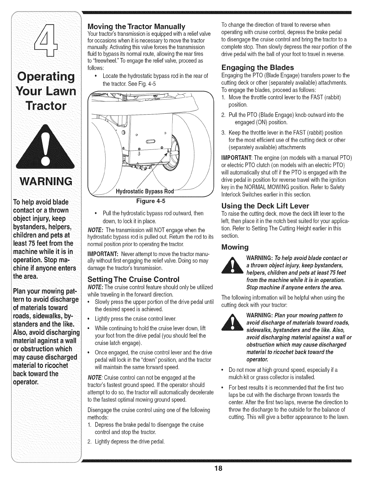
Moving the Tractor Manually
Yourtractor'stransmissionisequippedwitha reliefvalve
foroccasionswhenitisnecessaryto movethetractor
manuallyActivatingthisvalveforcesthetransmission
fluidto bypassitsnormalroute,allowingthe reartires
to "freewheel."Toengagethe reliefvalve,proceedas
follows:
• Locatethe hydrostaticbypassrodinthe rearof
thetractor.See Fig.4-5
Hydrostatic Bypass
Figure 4=5
• Pullthe hydrostaticbypassrodoutward,then
down,to lockit in place.
NOTE: Thetransmissionwill NOTengagewhenthe
hydrostaticbypassrodis pulledout. Returnthe rodto its
normalpositionpriorto operatingthetractor.
IMPORTANT:Neverattemptto movethetractormanu-
allywithoutfirstengagingthe reliefvalve.Doingso may
damagethe tractor'stransmission.
Setting The Cruise Control
NOTE:The cruisecontrolfeatureshouldonly beutilized
whiletravelinginthe forwarddirection.
• Slowlypressthe upperportionof thedrive pedaluntil
thedesiredspeedis achieved.
• Lightlypressthecruisecontrollever.
• Whilecontinuingto holdthe cruiseleverdown,lift
yourfootfromthe drivepedal(you shouldfeel the
cruiselatchengage).
• Onceengaged,the cruisecontrolleverandthe drive
pedalwill lock inthe "down"position,andthe tractor
will maintainthe sameforwardspeed.
NOTE:Cruisecontrolcan notbe engagedat the
tractor'sfastestgroundspeed.Ifthe operatorshould
attemptto doso,the tractorwill automaticallydecelerate
to the fastestoptimalmowinggroundspeed.
Disengagethecruisecontrolusingoneof the following
methods:
1. Depressthe brakepedalto disengagethecruise
controlandstopthe tractor.
2. Lightlydepressthe drivepedal.
Tochangethe directionof travelto reversewhen
operatingwithcruisecontrol,depressthe brakepedal
to disengagethe cruisecontrolandbringthetractorto a
completestop.Thenslowlydepressthe rearportionof the
drivepedalwiththe ballof yourfootto travelin reverse.
Engaging the Blades
Engagingthe PTO(BladeEngage)transferspowerto the
cuttingdeckor other(separatelyavailable)attachments.
Toengagethe blades,proceedas follows:
1. Movethe throttlecontrolleverto the FAST(rabbit)
position.
2. Pullthe PTO(BladeEngage)knoboutwardintothe
engaged(ON)position.
.Keepthe throttleleverinthe FAST(rabbit)position
for the mostefficientuseof the cuttingdeckor other
(separatelyavailable)attachments
IMPORTANT:The engine(onmodelswitha manualPTO)
orelectric PTOclutch(on modelswith anelectricPTO)
will automaticallyshutoff if the PTOis engagedwiththe
drivepedalin positionfor reversetravelwiththe ignition
keyinthe NORMALMOWINGposition.Referto Safety
InterlockSwitchesearlierin thissection.
Using the Deck Lift Lever
Toraisethe cuttingdeck,movethe decklift leverto the
left, thenplaceit inthe notchbestsuitedforyour applica-
tion.Referto SettingThe CuttingHeightearlierin this
section.
Mowing
WARNING:Tohelp avoid blade contact or
a thrown object injury, keep bystanders,
helpers, children and pets at least 75feet
from the machine while it is in operation.
Stop machine ff anyone enters the area.
Thefollowinginformationwill behelpfulwhenusingthe
cuttingdeckwith yourtractor:
_ ARNING: Planyour mowing pattern to
avoid discharge of materials toward roads,
sidewalks, bystanders and the like. Also,
avoid discharging material against a wall or
obstruction which may cause discharged
material to ricochet back toward the
operator.
• Do not mowat highgroundspeed,especiallyif a
mulchkit orgrasscollectoris installed.
For bestresultsit is recommendedthatthe firsttwo
lapsbe cutwiththe dischargethrowntowardsthe
center.Afterthe first two laps, reversethedirectionto
throwthe dischargeto the outsidefor the balanceof
cutting.Thiswill givea betterappearanceto the lawn.
18

• Do notcut the grasstoo short.Shortgrassinvites 2, Pivotthe dischargechuteupto accessthe deck
weedgrowthandyellowsquicklyin dryweather, opening,SeeFig,4-6,
Mowingshouldalwaysbe donewiththe engineat full f
throttle.
• Underheavierconditionsit maybenecessaryto go
backoverthe cut areaa secondtimeto get a clean
cut.
• Do NOTattemptto mowheavybrushandweedsand
extremelytall grass.Yourtractoris designedto mow
lawns,NOTclearbrush.
• Keepthe bladessharpand replacethe bladeswhen
worn.Referto Cutting Blades inthe Maintaining
YourLawnTractor sectionof thismanualfor proper Figure 4=6
bladesharpeninginstructions.
Headlights 3. Insertthe mulchplug,aligningthe topedgeof the
• The lampsareONwheneverthe ignitionkeyis moved plugwiththe deckas shownin the Fig.4-6. Make
surethe notchesonthe plugarein the slotsonthe
outof the STOPposition, deckopening. ""
• The lampsturnOFFwhenthe ignitionkeyis movedto
the STOPposition. 4. Lightlytap onthe plugwithyourhandto assurethat NOTE: It is not
thenotchesfit snuglyunderthe chutetabs. necessaryto remove
Mulching (If so Equipped) the discharge chute to
Selectmodelscomeequippedwitha mulchkitwhich operatethe mowerwith
incorporatesspecialblades,alreadystandardonthe
tractor,ina processof recirculatinggrassclippings the mulch kit installed.
repeatedlybeneaththe cuttingdeck.Theultra-fine
clippingsarethen forcedbackintothe lawnwherethey
actas a naturalfertilizer.Observethe followingpointsfor
the bestresultswhenmulching:
• Neverattemptto mulchif the lawnis damp.Wetgrass
tendsto stickto theundersideof the cuttingdeck
preventingpropermulchingof the clippings.
• Do NOTattemptto mulchmorethan 1/3the total
heightof the grassor approximately1-1/2inches.
Doingso willcausetheclippingsto clumpup beneath
thedeckand notbe mulchedeffectively.
• Maintaina slowgroundspeedto allowthe grass
clippingsmoretimeto effectivelybemulched.
• Alwayspositionthe throttlecontrolleverinthe FAST
(rabbit)positionandallowit to remaintherewhile
mowing.Failingto keepthe engineat full throttle
placesstrainon the tractor'sengineand doesnot
allowthe bladesto properlymulchgrass.
NOTE:It is not necessaryto removethe dischargechute
to operatethe mowerwiththe mulchkit installed.
Tooperatethe cuttingdeckwithoutmulching,simply
removethe mulchplugbypivotingthe dischargechute
upand pullingtheplugoutward.
Toreinstallplug:
1. Locatetworectangularholesonthe cuttingdeck
surface.
19
Your Lawn
i i

TractOr
WARNING
ii_i ii i _i i iiiiiiii /_
Neverattemptto
make any adjust,
,ments while the
engine is running,
exceptwhere specl,
i
lied in the operator's
manual
Never attempt to
adjust the brakes
while the engine
is running: Always
disengage PTO,move
i
shift lever into neutral
position; stop engine
and remove key to
prevent unintended
NOTE: Check the
,
tractors t!re pressure
before performing any
deck levelingadjust-
ments:RefertOTires
in the Maintaining Your
Tractor section of this
manualfor information
_ARNING:Neverattempt to makeany
adjustments while the engine is running,
except where specified in the operator's
manual.
Side to Side
If the cuttingdeckappearsto bemowingunevenly,a side
to side adjustmentcan beperformed.Adjustif necessary
as follows:
Leveling the Deck 1.
NOTE:Checkthe tractor'stire pressurebeforeperform-
inganydeck levelingadjustments.Referto Tires inthe
MaintainingYour Tractor sectionof thismanualfor
informationregardingtire pressure. 2.
Front To Rear
Thefrontof the cuttingdeckissupportedbya stabilizer
barthatcanadjustedto levelthe deckfromfrontto
rear.The frontof the deckshouldbe between1/4-inch
and3/8-inchlowerthanthe rearof the deck.Adjustif
necessaryas follows:
Withthe tractorparkedona firm,levelsurface,place
the decklift leverin the top notch(highestposition)
androtateboth bladesso thattheyareperpendicular
withthe tractor.
.
Measurethe distancefrom the outsideof the leftblade
tip to the groundandthe distancefromtheoutsided
the rightbladetip to theground.Bothmeasurements
takenshouldbeequal. Ifthey'renot,proceedto the
nextstep.
Loosen,butdo NOTremove,the hexcap screwon
the leftdeckhangerbracket.SeeFig.5-2.
Withthe tractorparkedona firm,levelsurface,place
the decklift leverin the top notch(highestposition)
androtatethe bladenearestthe dischargechuteso
thatit is parallelwiththe tractor.
.Measurethe distancefrom the frontofthe blade
tip to the groundandthe rearof the bladetip to
the ground.Thefirst measurementtakenshould
bebetween1/4"and3/8" lessthanthe second
measurement.Determinethe approximatedistance
necessaryfor properadjustmentandproceed,if
necessary,to the nextstep.
3. Fromthe frontof thetractor,loosenthe outermost
hexlock nutonthe endof eachdeckhangerrod.
SeeFig.5-1.
.Tighteneachinnerhexnutfrontagainstthe front
hangerbracketto raisethe frontof the deck;loosen
eachhex nutto lowerthe frontof thedeck. SeeFig.
5-1.
Tghten
"\ to !owe_
Figure 5-1
5. Retightenbothlocknutsagainstthe innerhex nuts
whenproperadjustmentis achieved.
Figure 5=2
4. Balancethe deckby usingawrenchto turn the
adjustmentgear(foundimmediatelybehindthe hex
cap screwjust loosened)clockwise/uporcounter-
clockwise/down.Thedeckis properlybalancedwhen
bothbladetip measurementstakenearlierareequal.
5. Retightenthe hex capscrewonthe left deckhanger
bracketwhenproperadjustmentis achieved.
Parking Brake Adjustment
,_ WARNING:Neverattempt to adjust the
brakes while the engine is running. Always
disengage PTO,moveshift lever into
neutral position, stop engineand remove
key to prevent unintended starting.
ifthe tractordoesnotcometo acompletestopwhenthe
brakepedalis completelydepressed,orif the tractor'srear
wheelscan rollwiththeparkingbrakeapplied,the brakeis
in needof adjustment.SeeanauthorizedTroy-BiltService
Dealerto haveyourbrakesproperlyadjusted.
2O

Seat Adjustment
Quick Adjust Seat (if so equipped)
_ARNING:Beforeoperatingthismachine,
makesure the seat is engagedin the seat
stop, standbehind the machineandpuff
back on seat untilfullyengagedinto stop.
Toadjustthe positionof the seaton modelsequipped
witha seatadjustmentlever,movethe leverto the left
and slidethe seatforwardor rearward.Referto the
SettingUpYourLawnTractorsection.Makesure seat
is lockedintopositionbeforeoperatingthe tractor.
Knob Adjustment Seat (if so equipped)
Toadjustthe positionof the seaton modelsso equipped,
loosenthe twoknobson the bottomof theseat. See
Fig.5-3. Slidethe seatforwardor backwardas desired.
Retightenthe twoknobs.
Standard Seat (ifso equipped)
Toadjustthepositionofthe seat,loosenthetwohexscrews
onthebottomof theseat.Slidethe seatforwardor backward
as desired.Retightenthetwoscrews.SeeFig.5-4.
Steering Adjustment
Ifthe tractorturnstighterinonedirectionthanthe other,
or if the balljointsarebeingreplaceddue to damageor
wear,the steeringdraglinksmayneedto beadjusted.
Adjustthe draglinksso thatequallengthsare threaded
intothe balljointon the leftand rightside:
1. Loosenthejam nut foundonthe draglinkat the rear
of the balljoint.See Fig.5-5.
2. Removehex nuton thetop of balljoint.See Fig.5-5.
3. Threadthe balljoint towardthejam nut to shortenthe
draglink.Threadtheballjointawayfromthejamnut
to lengthenthe draglink.
4. Replacehex nutand retightenthejam nut afterproper
adjustmentis achieved.
NOTE:Threadingthe balljointstoo far ontothe draglinks
will causethe fronttiresto "toe-in"too far.Propertoe-in is
between1/16"and5/16".
Fronttiretoe-in canbe measuredas follows:
1. Placethe steeringwheelinpositionfor straightahead
travel.
2. Infrontof the axle,measurethe distancehorizontally
fromthe insideof the leftrimto the insideof the right
rim.Notethe distance.
3. Behindthe axle,measurethe distancehorizontally
fromthe insideof the leftrimto the insideof the right
rim.Notethe distance.
4. The measurementtakeninfrontof the axle shouldbe
between1/16"and5/16"lessthanthe measurement
takenbehindthe axle.Adjustif necessary.
Figure 5-3
f
Figure 5=4
Figure 5=5
Adjusting
Beforeoperating this
machine, make sure
the seat is engaged in
the seat stop, stand
behind the machine
and pull back on seat
stop:
NOTE: Threadingthe
ball joints too far onto
the drag linkSWill Cause
the front tires to 'ttoeqn'!
tOOfarlProper t!eqn
is bt!ween i/i6 and
5ii61
21

WARNING
Beforeperforming
anymaintenanceor
repairs,disengage
PTO, move shift lever
intoneutralposition,
set parking brake,
stop engine and
remove keyto prevent
unintendedstarting.
Before lubricating,
repairing, or inspect-
ing,always disengage
PTO, move shift lever
into neutral position,
set parking brake,
stop engine and
remove key to prevent
unintendedstarting.
KohlerTwinShown
Figure 6-1
_ARNING:Before performing any
maintenanceor repairs,disengagePTO,
moveshift lever into neutral position, set
parking brake,stop engine and remove
key to prevent unintended starting.
Engine
Referto the EngineOperator/Owner Manualfor
engine maintenance instructions.
Checkengineoil level beforeeachuseas instructed
inthe EngineOperator/OwnerManualpackedwithyour
unit.Follow the instructionscarefully.
Changing Engine Oil
.
3.
.
Popopenthe protectivecap onthe endof the oil
drainvalveto exposethedrain port.
Removethe oil fill cap/dipstickfromthe oil fill tube.
Pushtheoildrainhose(packedwiththismanual)onto
theoildrainport.Routetheoppositeendofthehoseinto
anappropriateoilcollectioncontainerwithacapacity
greatenoughtocollecttheusedoil.SeeFig.6-1.
Pushthe drainvalveinandturn counter-clockwiseto
releasevalveto drainoil.
.
.
Afterthe oil has finisheddraining,pushtheoil drain
valvebackin, rotateit clockwiseto lockthe valve
closedand re-capthe endof the oil drainvalveto
keepdebrisfromenteringthedrainport.
Servicethe oilfilter (if so equipped)as instructedin
the separateEngineOperator/OwnerManualpacked
withyourunit.
Performthe abovestepsinthe oppositeorderafteroil
hasfinisheddraining.
7. Refilltheenginewithnewmotoroilas instructedinthe
EngineOperator/OwnerManualpackedwithyourunit.
IMPORTANT:Referto the EngineOperator/Owner
Manualpackedwithyourunit for informationregarding
thequantityandproperweightof motoroil.
Air Cleaner
Servicethe pre-cleaner,if soequipped,andcartridge/air
cleanerelementas instructedin the EngineOperator/
OwnerManualpackedwithyour unit.
Spark Plug(s)
Thesparkplug(s)shouldbecleanedand thegap reset
oncea season.Sparkplugreplacementis recommended
at the startof each mowingseason.Referto the Engine
Operator/OwnerManualfor correctplugtypeandgap
specifications.
Lubrication
_ARNING:Before lubricating, repairing, or
inspecting, always disengage PTO,move
shift lever into neutral position, set parking
brake, stop engine and remove key to
prevent unintended starting.
Engine
Lubricatethe enginewithmotoroil as instructedinthe
EngineOwnerManualpackedwith yourunit.
Pivot Points & Linkage
Lubricateall the pivotpointsonthe drivesystem,parking
brakeand lift linkageat leastoncea seasonwithlightoil.
Rear Wheels
The rearwheelsshouldbe removedfrom the axlesonce
a season.Lubricatethe axlesandthe rimswell withan
all-purposegreasebeforere-installingthem.
Front Axles
Eachendof the tractor'sfrontpivotbarmaybeequipped
witha greasefitting.Lubricatewitha greasegunafter
every25 hoursof tractoroperation.
Cleaning the Engine And Deck
Anyfuel oroil spilledonthe machineshouldbe wiped
off promptly.Do NOTallowdebristo accumulatearound
the coolingfinsof the engineor onany otherpart of the
machine.
IMPORTANT:The useof a pressurewasherto cleanyour
tractoris NOTrecommended,it maycausedamageto
electricalcomponents,spindles,pulleys,bearingsor the
engine.
22

Deck Wash System TM
Twowaterportsareavailableonyour mowerdeckto
be usedas partof the deckwashsystem.Usethe
DeckWashSystemTM to rinsegrassclippingsfromthe
deck'sundersideand preventthe buildupof corrosive
chemicals.
If yourtractoris notalreadyequippedwitha Deck
WashSystemTM then a hexplugcan befoundonyour
tractor'sdecksurface.Thisplugcan bereplacedwith a
separately-availableDeckWashSystemTM.
NOTE:Referto theAttachments&Accessoriessectiondthis
manualforinformationregardingthisandotherseparately-
availableattachments&accessoriesforyourtractor.
Toutilizethe DeckWashSystemTM, completethefollow-
ingstepsAFTEREACHMOWING:
1. Drivethe tractorto a level,clear spoton yourlawn,
nearenoughto a watersillcock(spigot)for your
gardenhoseto reach.
IMPORTANT:Makecertainthe tractor'sdischargechuteis
directedAWAYfromyourhouse,garage,parkedcars,etc.
.
.
.
Disengagethe PTO(BladeEngage),movethe shift
leverintothe neutralposition,setthe parkingbrake,
andstopthe engine.
Threadthe hosecoupler(packagedwithyourtractor's
Operator'sManual)ontothe endof yourgardenhose.
Attachthe hosecouplerto the waterport onyour
deckssurface.SeeFig.6-2.
5. Turnthe wateron.
.
.
8.
.
Whilesittingin theoperator'spositiononthe tractor,
re-starttheengineandplacethethrottle leverin the
FAST(rabbit)position.
Disengagethe parkingbrake.
Movethe tractor'sPTO(BladeEngage)intothe ON
position.
Remainin the operator's positionwiththecutting
deckengagedfor a minimumof twominutes,allowing
the undersideof the cuttingdeckto thoroughlyrinse.
10.Movethe tractor'sPTO(BladeEngage)intothe OFF
position.
11.Turnthe ignitionkey to the STOPpositionto turn the
tractor'sengineoff andengagethe parkingbrake.
12.Turnthe wateroff anddetachthe hosecouplerfrom
thewaterport onyourdeckssurface.
13.Repeatsteps4-11on theoppositesideof the cutting
deck.
Figure 6=2
Figure 6=3
Cutting Deck Removal
To removethe cuttingdeck,proceedas follows:
1. Placethe PTO/BladeEngageknob inthe disengaged
(OFF)positionandengagetheparkingbrake.
2. Lowerthedeck bymovingthe decklift leverintothe
bottomnotchon the rightfender.
3. Removethe deckbeltfrom aroundthe tractor's
electricPTOclutch(referto Changingthe DeckBelt).
4. Lookingat thecuttingdeckfromthe leftside of the
tractor,locatethe decksupportpinon the rearleft
sideof the deck.
5. Rotatethe pinslightlytowardthe rearof the tractor
and releaseit.
6. Pullthe decksupportpinoutwardto releasethe deck
fromthe deckliftarm.See Fig.6-3.
23
iMPORTANT
Make certain the
tractor's discharge chute
is directed AWAYfrom
your house, garage,
parkedcars. etc.

7, Repeatthe abovestepsonthe tractor'srightside, Charging
WARNING
Never exceed the
maximum inflation
pressure shown on
the sidewall of the
tire.
Batteries give off an
explosive gaswhile
charging. Charge
battery in awell
ventilated area and
keep away from an
open flame or pilot
light as on a water
heater, space heater,
furnace, clothes
dryer or other gas
appliances.
When removing or
installingthe battery,
follow these instruc-
tions to preventthe
screwdriver from
shorting against the
frame.
,
,
Movethe decklift leverintothe top notchto raisethe
decklift armsupand outof the way.
Gentlyslidethe cuttingdecktowardthe frontof the
tractorallowingthe hooksonthe deckto release
themselvesfromthe deck stabilizerrod.
10.Gentlyslidethe cuttingdeck(fromthe rightside)out
fromunderneaththetractor.
11.Pullthe decksupportpinoutwardto releasethe deck
fromthedecklift arm.
12.Rotatethe pin slightlytowardthe rearof the tractor
andreleasethe pin intothe holeprovided.
13.Repeatthe abovestepsonthe tractor'srightside.
IMPORTANT:Whenchargingyourtractor'sbattery,use
onlya chargerdesignedfor 12Vlead-acidbatteries.Read
yourbatterycharger'sOwner'sManualpriorto charging
yourtractor'sbattery.Alwaysfollowitsinstructionsand
heeditswarnings.
If yourtractorhasnot beenputinto usefor an extended
periodof time,chargethe batteryas follows:
• Setyour batterychargerto delivera maximumof 10
amperes.Ifyour batterychargeris automatic,charge
the batteryuntilthe chargerindicatesthatchargingis
complete.
NOTE:Ifthe chargeris notautomatic,chargefor no fewer
thaneight hours.
14.Movethe decklift leverintothe top notchonthe right
fenderto raisedeckliftarmsupandout of the way.
15.Gentlyslidethe cuttingdecktowardthe frontof the
tractorallowingthe hooksonthe deckto release
themselvesfromthe deck stabilizerrod.
16.Gentlyslidethe cuttingdeck(fromthe rightside)out
fromunderneaththetractor.
Tires
,_ WARNING:Neverexceed the maximum
inflation pressure shown on the sidewall
of tire.
The recommendedoperatingtire pressureis:
_k ARNING:Batteries give off an explosive
gas while charging. Charge battery in a
well ventilated areaand keep away from
an open flame or pilot light as on a water
heater,space heater,furnace, clothes dryer
or other gas appliances.
Jump Starting
_k ARNING:Whenremoving or installing the
battery, follow these instructions to prevent
the screwdriver from shorting against the
frame.
IMPORTANT:Neverjumpyourtractor'sdeadbatterywith
the batteryof a runningvehicle.
Approximately10psifor the reartires
Approximately14psi for the fronttires
IMPORTANT:Referto the tire sidewallforexacttire
manufacturer'srecommendedormaximumpsi.Do not
overinflate.Uneventirepressurecouldcausethe cutting
deckto mowunevenly.
Battery
The batteryis sealedandis maintenance-free.Acid
levelscannotbechecked.
Alwayskeepthe batterycablesandterminalsclean
andfreeof corrosivebuild-up.
Aftercleaningthe batteryandterminals,apply a light
coatof petroleumjelly or greaseto bothterminals.
Alwayskeepthe rubberboot positionedoverthe
positiveterminalto preventshorting.
1. Connectendof onejumpercableto the positive
terminalof the goodbattery,thenthe otherendto the
positiveterminalof the deadbattery.
2. Connectthe otherjumpercable to the negative
terminalof the goodbattery,thento the frame of the
unit with the dead battery.
_1 WARNING:Failure to use this procedure
could cause sparking, and thegas in either
battery could explode.
Cleaning
Cleanthe batteryby removingit fromthe tractorand
washingwitha bakingsodaandwatersolution.If neces-
sary,scrapethe batteryterminalswith a wire brushto
removedeposits.Coatterminalsandexposedwiringwith
greaseor petroleumjelly to preventcorrosion.
Battery Failures
IMPORTANT:Ifremovingthe batteryfor anyreason,
disconnectthe NEGATIVE(Black)wire fromit's terminal
first,followedby the POSITIVE(Red)wire.When
re-installingthe battery,alwaysconnectthe POSITIVE
(Red)wire its terminalfirst,followedby the NEGATIVE
(Black)wire.Becertainthatthewiresareconnectedto
thecorrectterminals;reversingthemcouldchangethe
polarityandresultindamageto your engine'salternat-
ingsystem.
Somecommoncausesfor batteryfailureare:
• incorrectinitialactivation • undercharging
• overcharging • corrodedconnections
• freezing
NOTE:ThesefailuresareNOTcoveredbyyour tractor's
warranty.
24

Cutting Blades
_ ARNING: Besure to shut the engine
off, remove ignition key,disconnect the
spark plug wire(s) and ground against
the engine to prevent unintended starting
before removing the cutting blade(s) for
sharpening or replacement. Protect your
hands by using heavy gloves or a rag to
grasp the cutting blade.
WARNING: Periodically inspect the blade
spindles for cracks or damage, especially
if you strike a foreign object. Replace
immediately if damaged.
The bladesmayberemovedas follows.
1. Removethe deckfrombeneaththe tractor,(referto
CuttingDeckRemovalon page23) thengentlyflip
thedeckoverto exposeitsunderside.
2. Placea blockof wood betweenthe centerdeckhous-
ingbaffleandthe cuttingbladeto act as a stabilizer.
SeeFig.6-4.
3. Removethe hexflangenutthat securesthe bladeto
the spindleassembly.SeeFig.6-4.
4. Toproperlysharpenthe cuttingblades,removeequal
amountsof metalfrombothends of the bladesalong
thecutting edges,parallelto the trailingedge,at a
250to 300angle.
IMPORTANT:Ifthe cuttingedgeof the bladehasalready
beensharpenedto within15/8" fromtheedge,or if any
metalseparationis present,replacethe bladeswith new
ones.SeeFig.6-5.
• It is importantthateachcuttingbladeedgebeground
equallyto maintainproperbladebalance.
• Whenreplacingtheblade,be sureto installthe blade
withthe sideof the blademarked"Bottom" (orwith
a part numberstampedinit) facingthe groundwhen
the moweris inthe operatingposition.
IMPORTANT:Usea torquewrenchto tightenthe blade
spindlehexflangenutto between70foot-poundsand90
foot-pounds.
Fuses
Afuse is installedinyourtractor'swiringharnessto
protectthe tractor'selectricalsystemfromdamage
causedby excessiveamperage.
If theelectricalsystemdoesnot function,oryour
tractor'senginewill not crank,firstcheckto becertain
thatthe fusehasnot blown.
• It caneither befoundunderthe hoodmountedbehind
thetop of the dash panelonthe supportbar,or under
the seatmountedto the insideof the tractorframe
nextto the batterytray.
IMPORTANT:Alwaysusea fusewiththe sameamper-
agecapacityfor replacement.
f'_ He×Flange Nut "_
Figure 6-4
\
Figure 6-5
Maintaining
WARNING
Be sure to shut
the engine off,
remove ignition key,
disconnect the spark
plug wire(s) and
groundagainst the
engine to prevent
unintended starting
before removing
the cutting blade(s)
for sharpening or
replacement. Protect
your hands by using
heavy glovesor arag
to grasp the cutting
blade.
Periodically inspect
the blade spindles for
cracks or damage,
especially if you strike
a foreign object.
Replace immediately if
damaged.
25

Maintaining
WARNING
Be sure to shut
the engine off,
removeignition key,
disconnectthe spark
plugwire(s) and
groundagainstthe
engine to prevent
unintended starting
before removingthe
belt(s).
Avoidthe possibilityof
a pinchinginjury.Do
notplaceyour fingers
on the idler springor
betweenthe belt and a
puley while removing
the belt.
Changing the Deck Belt
_ARNING:Besureto shutthe engineoff,
removeignition key,disconnect the spark
plug wire(s) andground against the engine
to prevent unintended starting before
removingthe belt(s).
WARNING:Avoid the possibilityof a
pinchinginjury. Donot placeyour fingers
on the idler spring or between the belt and
apulley while removing the belt.
Allbeltsonyourtractoraresubjectto wearandshouldbe
replacedifanysignsof weararepresent.
iMPORTANT:The V-beltsfoundonyourtractorare
speciallydesignedto engageanddisengagesafely.A
substitute(non-OEM)V-beltcan bedangerousby not
disengagingcompletely.Fora properworkingmachine,
usefactoryapprovedbelts.
Tochangeor replacethe deckbelt onyourtractor,
proceedas follows:
1. Lowerthe deckby movingthe deck liftleverintothe
bottomnotchonthe rightfender.
2. Removethe beltguardsby removingthe self-tapping
screwsthatfastenthemto the deck.
3. Toeaseinremovingthe belt inlater steps,loosen,
butdo not remove,the boltwhichsecuresthe
pivotingidlerpulleyto the idlerbracket.SeeFig.6-6.
Pivoting Idler Pulley Belt Guard
/
"Square
Hole
NOTE:Theidlerpulleysmayhaveto beloosened,but not
removed,inorderto removethe beltfromaroundthem.
8. Routethe newbeltsas shownbelowin Fig.6-7or 6-8.
9. Retightenthe bolt whichsecuresthe pivotingidler
pulleyto the idlerbracket.
10.Remountthe beltguardsremovedearlier.
Changing the Transmission Drive Belt
NOTE:Severalcomponentsmustbe removedandspecial
tools(i.e.air/impactwrench)inorderto changethe
tractor'sdrive belt.Seean authorizedMTDServiceDealer
to haveyourdrivebelt replacedor phoneCustomerSup-
portas instructedonpage2 for informationonorderinga
ServiceManual.
4. Inserta 3/8"-driveratchetwrench(setto tighten)into
the squareholefoundin the idlerbracketon the left
sideof the deck'ssurface.SeeFig.6-6.
5. Graspthe ratchet'shandleandpivotit to relieve
tensiononthe belt.
6. Withbelttensionrelieved,carefullyremovethe belt
fromaroundthe left-handspindlepulley.
IMPORTANT:Carefullyallowthe ratchetto pivotrearward
beforeremovingit fromthe squarehole.
7. Removethe deckbelt fromaroundall pulleys,
includingthe deckidlerpulley(s)andthe electric
PTOclutch.
26

d50oinchDeck
(Electric PTO)
J
Figure 6=7
54-inch Deck
(Electric PTO)
Figure 6=8
27
Tractor

WARNING
iDrainfuel only into an
approvedcontainer
outdoors,away
ifrom anopenflame.
iAllowengineto cool.
iExtinguishcigarettes,
'cigars, pipes, and
other sources
of ignition priorto
,drainingfuel.
i Never store the
i machine or fuel
container indoors
_where there is an
open flame, spark or
ipilot light such as on
water heater, furnace,
clothes dryer or other
gas appliance.
Cleanandlubricatethe tractoras instructedin the Followthe instructionsin the Service, Storage &
MAiNTAiNiNGYOURLAWNTRACTORsectionof this Specifications sectionof the EngineOperator/Owner
manualbeforestoringfor anextendedperiod. Manualfor properenginecare priorto storingyourtractor.
_i= ARNING:Drainfuel only intoan approved
containeroutdoors,awayfrom anopen
flame.Allowengineto cool. Extinguish
cigarettes,cigars, pipes,andothersources
of ignitionpriorto drainingfuel.
,A_ WARNING:Neverstorethe machineor fuel
container indoorswhere there is an open
flame, spark or pilotlightsuch as on water
heater,furnace, clothes dryer or othergas
appliance.
Attachments & Accessories
Thefollowingattachmentsandaccessoriesarecompatiblefor ModelSeries620 LawnTractors.Seethe retailer
fromwhichyou purchasedyourtractor,an authorizedMTDServiceDealeror phone(800) 800-7310for information
regardingpriceandavailability.
NOTE:ModelSeries620 LawnTractorsare NOTdesignedfor usewithany typeof ground-engagingattachments
(e.g.tiller or plow).Useof thistypeof equipmentWILLvoidthe tractor'swarranty.
MODEL DESCRiPTiON
OEM-190-032 42-inchTwo-stageSnowThrower
OEM-190-193 50-inch DeckMulchKit
OEM-190-013 54-inch DeckMulchKit
OEM-190-192 TripleBaggerGrassCollector(for 50-inchDecks)
OEM-190-842 TripleBaggerGrassCollector(for 54-inchDecks)
OEM-190-607" DeluxeTractorSunshade
OEM-190-671 Tire Chains,20x 8 Tires
OEM-190-784 WheelWeights
OEM-190-751 SnowCab
0EM-190-672 GrilleGuard(mountsonfrontof tractor)
0EM-190-833 46-inch FrontDozerBlade
790-900-0025 DeckWashKit
* Notcompatiblewithtractorsequippedwitha GrassCollector
28

ROTATING BLADES CAUSE
SERIOUS INJURY OR DEATH
*DONOTMOWWHENCHILDRENOR
OTHERSAREAROUND
*NEVERCARRYCHILDRENEVENWiTH
BLADE(S)OFF,
* LOOKDOWNANDBEHINDBEFORE
ANDWHILEBACKING,
0
29
Labels
WARNING
The abovesymbol
pointsout important
safety instructionsin
this manualwhich, if
notfollowed,could
endangerthe personal
safetyand/or property
of yourselfand others.
Readandfollowall
instructionsinthis
manualbeforeat-
temptingto operate
this machine.Failure
to complywiththese
instructionsmay result
in personalinjury.When
you see this symbol.
HEED ITS WARNING!
Your Responsibility
Restrictthe use
of this power machine
to persons who read,
understand
and follow the warnings
and instructions
inthis manual
and onthe machine.

For repairs beyond
the minor adjust-
ments listed here,
contact an authorized
service dealer.
Pro bl em Ca use Remedy
Enginefails to start 1. PTOengaged• 1. PlacePTOknobindisengaged
(OFF)position•
2. Sparkplugwire(s)disconnected. 2. Connectwire(s)to sparkplug(s)•
3 Fueltankem t or stalefuel 3 F tankwthc ean freshgaso ne
• py ••
4 Chokenot actvated 4. Pullout the CHOKEcontrol(if so
•equipped)orplacethe throttle
controlinCHOKEposition•
5. Faultysparkplug• 5. Clean,adjustgap,or replace•
6. Blockedfuel line• 6. Cleanfuel lineor replacefuelfilter,
7. Engineflooded, if so equipped.
7. Crankenginewiththrottle in FAST
position.
8. Parkingbrakenotengaged. 8. Engageparkingbrake.
' 9. Throttlecontrollevernotin correct 9. Placethrottleleverto FAST
- startingposition. .position.
Engineruns erratic 1. UnitrunningwithCHOKEapplied. 1. PushCHOKEcontrolin.
2. Sparkplugwire(s)loose.
3. Blockedfuellineor stalefuel.
4. Ventingas cap plugged.
5. Waterordirt infuel system.
6. Dirty aircleaner.
_ J _ =_
3O
2. Connectandtightenspark
plugwire(s).
3. Cleanfuel line;fill tankwith clean,
fresh(lessthan30 daysold)
gasoline.Replacefuel filter,if so
equipped.
4. Clearventor replaceif damaged.
5. Drainfuel tank. Refillwith
freshfuel.
6. Replaceaircleanercartridge/ele-
mentor cleanpre-cleaner,if so
equipped.
_ i

Problem Cause Remedy
Engine overheats 1! Engine0il level!0wl i: FillCrankcasewith pi0peroi!,
2. Air flowrestricted. Clean grassClippingsanddebis
fromaroundthe engneScoo!ing
....... finsandblowerhousing.
Enginehesitates at 1. Sparkplug(s)gaptooclose. 1. Removesparkplug(s)and reset
high RPM the gap.
desp0or 1 Sparkpug(s)foued fautyorgap 1 Repacesparkpug(s) Setpug(s)
Y '
too wide. gap.
2 Dirtyair Cleaner. 2 Replaceaircleaner cartridgeielei
....... equipped.
Excessive 1. Cuttingbladelooseorunbalanced. 1. Tightenbladeandspindle.Balanc_
blade.
Vibration
2. Damagedorbentcuttingblade. 2. Replaceblade.
Mower will not li EngineSpeedtoo low, 1: Placethrottle controlin FAST
mulch grasS(f Wetgra_ (rabbit)position:
E J 2 Do not mowwhengrass swet;
qu pped) .... •wat unt aterto cut
3. Excessivey hgh grass: 3. Mowonce at a highcuttingheight,
then mowagainat desiredheight
or makea narrowerCuttingpathl
Duilblade 4. sharpenOrreplaceblade:
Unevencut 1. Decknotbalancedproperly. 1. Performside4o-sidedeckadjust-
2. Dullblade, mont.
2. Sharpenor replaceblade.
3. Uneventire pressure.
3. Checktire pressureinall fourtires.
31

)¸¸¸lfasafetyfeature
is notfunctioning
properlyido not use
the tractor.Contact
iyour authorizedMTD
service dealeror call
(800>8oo,73 o:
This Operators
ManUalcovers a range
of product specifications
for VariousmodelS:
CharacteriSticsand
features discUssed
and/or illustratedin
this manual may not be
appliCabletOal! roodels:
MTD LEOreserves the
right to changeprOduCt
specifications designs
and equipmentWitllout
notice and without
ncurring obligationl
NOTE:Downloada completePartsManualfreeof chargeat www.mtdproducts.comor phone(800)800-7310to
purchasea PartsManual.Besureto haveyourmodelnumberandserialnumberready.Thesecanbe foundonthe
modelplatelocatedunderthe seat.Referto page2 for moreinformationregardinglocatingyourmodelandserial
numbers.
DriveBelt (Transmission) 754-0461
DriveBelt (MowingDeck)50" Deck 754-04107
DriveBelt (MowingDeck)54" Deck 754-0642
DeckBlade(50" Deck)three each 742-04053A
DeckBlade(54" Deck)CenterBlade 742-0677
DeckSpindle(50"Deck) 618-04126A
DeckSpindle(54"Deck) 618-04125A
RearDeckWheels5.0x 1.38(50"Deck) 734-0973
FrontDeckWheels5.0dia. ball(50" Deck) 734-04155
DeckWheels5.0 dia. ball(54" Deck) 734-04155
Battery 925-1707D
Tire (Front)15"x 6" x 6" SquareShoulder 734-1731
Tire (Rear)22"x 9.5"x 12"SquareShoulder 734-04174
HubCap 731-05674
FuelTankCap 951-3111
ChokeControlCable(KohlerTwinCylinder) 746-1085A
ThrottleControlCable(KohlerTwinCylinder) 746-1086
DischargeChuteAssembly 631-04070A
_ARNING: If a safety featureis not functioningproperly, do not use the tractor. Contact
your authorized MTDservice dealer or call (800)800-7310.
32

NOTES
Use this page to make notes and write down important information.
33

NOTES
Use this page to make notes and write down important information.
34

CALIFORNIA EMISSION CONTROL WARRANTY STATEMENT
YOUR WARRANTY RIGHTS AND OBLIGATIONS
The CaliforniaAir ResourcesBoardandMTDConsumerGroupInc are pleasedto explainthe evaporativeemissioncontrolsystemwarrantyon your 2007lawn
mower.In California,new lawnmowermust be designed,builtand equippedto meet theState'sstringentanti-smogstandards.MTDConsumerGroupInc must
warrantthe EECSon yourlawn mowerfor the periodof time listedbelow providedthere hasbeenno abuse,neglector impropermaintenanceof your lawnmower.
YourEECSmayincludeparts suchas thecarburetor,fuel-injectionsystem,the ignitionsystem,catalyticconverter,fueltanks,fuel lines,fuelcaps,valves,
canisters,filters,vaporhoses,clamps,connectors,and otherassociatedemission-relatedcomponents.
Where a warrantable condition exists, MTDConsumer Group Inc will repair your lawn mower at no cost to you includingdiagnosis, parts and labor.
MANUFACTURER'S WARRANTY COVERAGE:
Thisevaporativeemissioncontrolsystemis warrantedfor two years.If anyevaporativeemission-relatedpart on yourequipmentis defective,the partwill be
repairedor replacedby MTDConsumerGroupInc.
OWNER'S WARRANTY RESPONSIBILITIES:
Asthe lawn mowerowner,youare responsiblefor performanceof the requiredmaintenancelistedin yourowner'smanual. MTDConsumerGroupIncrecom-
mendsthat youretainall receiptscoveringmaintenanceonyour lawnmower,but MTDConsumerGroup Inccannotdenywarrantysolelyforthe lack of receipts.
Asthe lawn mowerowner,youshouldhoweverbeawarethat MTDConsumerGroupInc maydeny youwarrantycoverageif your lawnmoweror a part hasfailed
dueto abuse,neglect,orimpropermaintenanceor unapprovedmodifications.
Youare responsiblefor presentingyourlawn mowerto MTDConsumerGroupInc'sdistributioncenteror servicecenteras soonas the problemexists.The
warrantyrepairsshouldbecompletedin a reasonableamountof time, notto exceed30 days.If you havea questionregardingyour warrantycoverage,youshould
contactthe MTDConsumerGroupIncService Departmentat 1-800-800-7310.
GENERAL EMISSIONS WARRANTY COVERAGE:
MTDConsumerGroupIncwarrantsto the ultimatepurchaserand eachsubsequentpurchaserthat the lawnmoweris: Designed,built andequippedso as to
conformwithall applicableregulations;andfree from defectsin materialsand workmanshipthat causethe failureof a warrantedpart to beidenticalin allmaterial
respectsto that part as describedin MTDConsumerGroupInc'sapplicationfor certification.
The warrantyperiodbeginsonthedate the lawnmoweris deliveredto an ultimatepurchaseror first placed intoservice.The warrantyperiodis two years.
Subjectto certainconditionsand exclusionsas statedbelow,the warrantyonemission-relatedpartsisas follows:
1. Anywarrantedpartthat is notscheduledfor replacementas requiredmaintenanceinthe writteninstructionssupplied,is warrantedfor thewarrantyperiod
statedabove.Ifthe part fails duringthe periodof warrantycoverage,the partwillbe repairedor replacedby MTDConsumerGroupInc accordingto subsection
(4)below.Anysuchpart repairedor replacedunderwarrantywillbe warrantedfor the remainderof the period.
2. Anywarrantedpart that is scheduledonly for regularinspection inthe writteninstructionssuppliedis warrantedfor thewarranty periodstated above.Any such
partrepairedor replacedunderwarrantywill bewarrantedfor the remainingwarrantyperiod.
3. Anywarrantedpart that is scheduledfor replacementas requiredmaintenancein thewritten instructionssuppliedis warrantedforthe periodof time beforethe
firstscheduledreplacementdatefor that part.If the partfails beforethe firstscheduledreplacement,the part willbe repairedor replacedby MTDConsumer
GroupInc accordingto subsection(4) below.Any such part repairedor replacedunderwarrantywillbe warrantedforthe remainderof the periodpriorto the
firstscheduledreplacementpointfor the part.
4. Repairor replacementof anywarrantedpart underthe warrantyprovisionshereinmustbe performedat a warrantystationat no chargeto theowner.
5. Notwithstandingthe provisionsherein,warrantyservicesorrepairswill be providedat all of our distributioncentersthat arefranchisedto servicethe subject
enginesor equipment.
6. Thelawnmowerowner willnot be chargedfor diagnosticlaborthat is directlyassociatedwithdiagnosisof a defective,emission-relatedwarrantedpart,
providedthat such diagnosticwork is performedat a warrantystation.
7. MTDConsumerGroupInc is liablefor damagesto otherengineor equipmentcomponentsproximatelycausedby a failure underwarrantyof any warranted
part.
8. Throughoutthe lawnmowerwarrantyperiodstated above,MTDConsumerGroupIncwill maintaina supplyof warrantedpartssufficientto meetthe expected
demandfor suchparts.
9. Anyreplacementpartmaybe usedinthe performanceof any warrantymaintenanceorrepairsand mustbe providedwithoutchargeto the owner.Suchusewill
notreducethe warrantyobligationsof MTDConsumerGroupInc.
10.Add-onor modifiedpartsthat arenotexemptedbythe Air ResourcesBoardmaynot beused.The useof any non-exemptedadd-onor modifiedparts bythe
ultimatepurchaserwillbegroundsfor disallowinga warrantyclaims. MTDConsumerGroup Incwill notbe liableto warrantfailuresof warrantedparts caused
bythe useof a non-exemptedadd-onor modifiedpart.
WARRANTED PARTS:
The repairor replacementof any warrantedpart otherwiseeligiblefor warrantycoveragemaybeexcludedfrom suchwarrantycoverageifMTDConsumerGroup
Inc demonstratesthat the lawnmowerhasbeenabused,neglected,or improperlymaintained,andthat suchabuse,neglect,or impropermaintenancewasthe
directcauseof the needfor repairor replacementof the part.Thatnotwithstanding,any adjustmentof a componentthathas a factory installed,and properly
operating,adjustmentlimiting deviceis still eligiblefor warrantycoverage.Thefollowing emissionwarrantyparts list arecovered: FuelLine,Fuel LineClamps

MANUFACTURER'S LiMiTED WARRANTY FOR
The limitedwarrantysetforthbelowisgivenby MTDLLCwithrespect
to newmerchandisepurchasedandusedin the UnitedStates,its
possessionsandterritories.
"MTD"warrantsthisproductagainstdefectsinmaterialandworkman-
shipfor a periodof two (2)yearscommencingonthe date of original
purchaseandwill,at its option,repairor replace,freeof charge,any
part foundto bedefectiveinmaterialsorworkmanship.Thislimitedwar-
rantyshallonlyapply if thisproducthasbeenoperatedand maintained
inaccordancewiththe Operator'sManualfurnishedwiththe product,
andhas notbeensubjectto misuse,abuse,commercialuse,neglect,
accident,impropermaintenance,alteration,vandalism,theft,fire,water,
ordamagebecauseof otherperilor naturaldisaster.Damageresulting
fromthe installationor useof any part,accessoryor attachmentnot
approvedby MTDfor use withthe product(s)coveredbythis manual
willvoid yourwarrantyas to any resultingdamage.
Normalwearpartsarewarrantedto befree fromdefectsinmaterialand
workmanshipfor a periodof thirty (30)daysfromthe dateof purchase.
Normalwearpartsinclude,butare notlimitedto itemssuchas: batter-
ies,belts,blades,bladeadapters,grassbags,riderdeckwheels,seats,
snowthrowerskidshoes,shaveplates,augerspiralrubberandtires.
HOW TO OBTAIN SERVICE: Warranty service is available,WITH
PROOFOF PURCHASE, through your local authorized service
dealer. To locate the dealer in your area, check your Yellow Pages,
or contact MTD LLC at RO. Box 361131,Cleveland, Ohio 44136-
0019, or call 1-800-800-7310or 1-330-220-4683 or log on to our
Web site at www.mtdproducts.com.
Thislimitedwarrantydoesnot providecoverageinthe followingcases:
a. Theengineor componentpartsthereof.Theseitemsmaycarrya
separatemanufacturer'swarranty.Referto applicablemanufacturer's
warrantyfor termsandconditions.
b. Logsplitterpumps,valves,andcylindershavea separateoneyear
warranty.
c. Routinemaintenanceitemssuchas lubricants,filters,blade
sharpening,tune-ups,brakeadjustments,clutchadjustments,deck
adjustments,andnormaldeteriorationof the exteriorfinishdueto
useor exposure.
d. Servicecompletedby someoneotherthananauthorizedservice
dealer.
e. MTDdoesnot extendanywarrantyfor productssoldor exported
outsideof the UnitedStates,its possessionsandterritories,except
thosesoldthroughMTD'sauthorizedchannelsof exportdistribution.
f. ReplacementpartsthatarenotgenuineMTDparts.
g. Transportationchargesandservicecalls.
No impliedwarranty,includingany impliedwarranty of mer-
chantabilityof fitness for a particular purpose,applies after the
applicable periodof express written warranty above as to the
partsas identified.No otherexpresswarranty, whetherwrittenor
oral, except as mentioned above,givenby any personor entity,
includingadealeror retailer, withrespect to any product,shall
bindMTD.Duringthe periodof the warranty,the exclusiveremedy
is repairor replacementof the productas setforth above.
Theprovisionsas set forth inthis warrantyprovidethe soleand
exclusiveremedy arising from the sale.MTDshallnot be liable
for incidentalor consequentiallossor damage including,without
limitation, expensesincurredfor substituteor replacementlawn
careservicesor for rentalexpensesto temporarily replacea
warranted product.
Somestatesdo notallowthe exclusionor limitationof incidentalor
consequentialdamages,or limitationsonhowlongan impliedwarranty
lasts,sothe aboveexclusionsor limitationsmaynot applyto you.
In noeventshallrecoveryof any kindbegreaterthanthe amountof the
purchasepriceof the productsold.Alterationof safetyfeatures of
the productshallvoid this warranty. Youassumethe riskandliability
for loss,damage,or injuryto you andyourpropertyand/orto othersand
theirpropertyarisingout of the misuseor inabilityto usethe product.
Thislimitedwarrantyshallnot extendto anyoneotherthan theoriginal
purchaserorto the personfor whomitwas purchasedas a gift.
HOWSTATELAWRELATESTOTHIS WARRANTY:This limited
warrantygivesyou specificlegalrights,and youmayalsohaveother
rightswhichvaryfromstateto state.
IMPORTANT:OwnermustpresentOriginalProofof Purchaseto obtain
warrantycoverage.
IVITDLLC, P.O. BOX 361131 CLEVELAND, OHiO 44136-0019; Phone: 1=800=800-7310, 1-330=220-4683
GDOO-lO0015 REV.A
