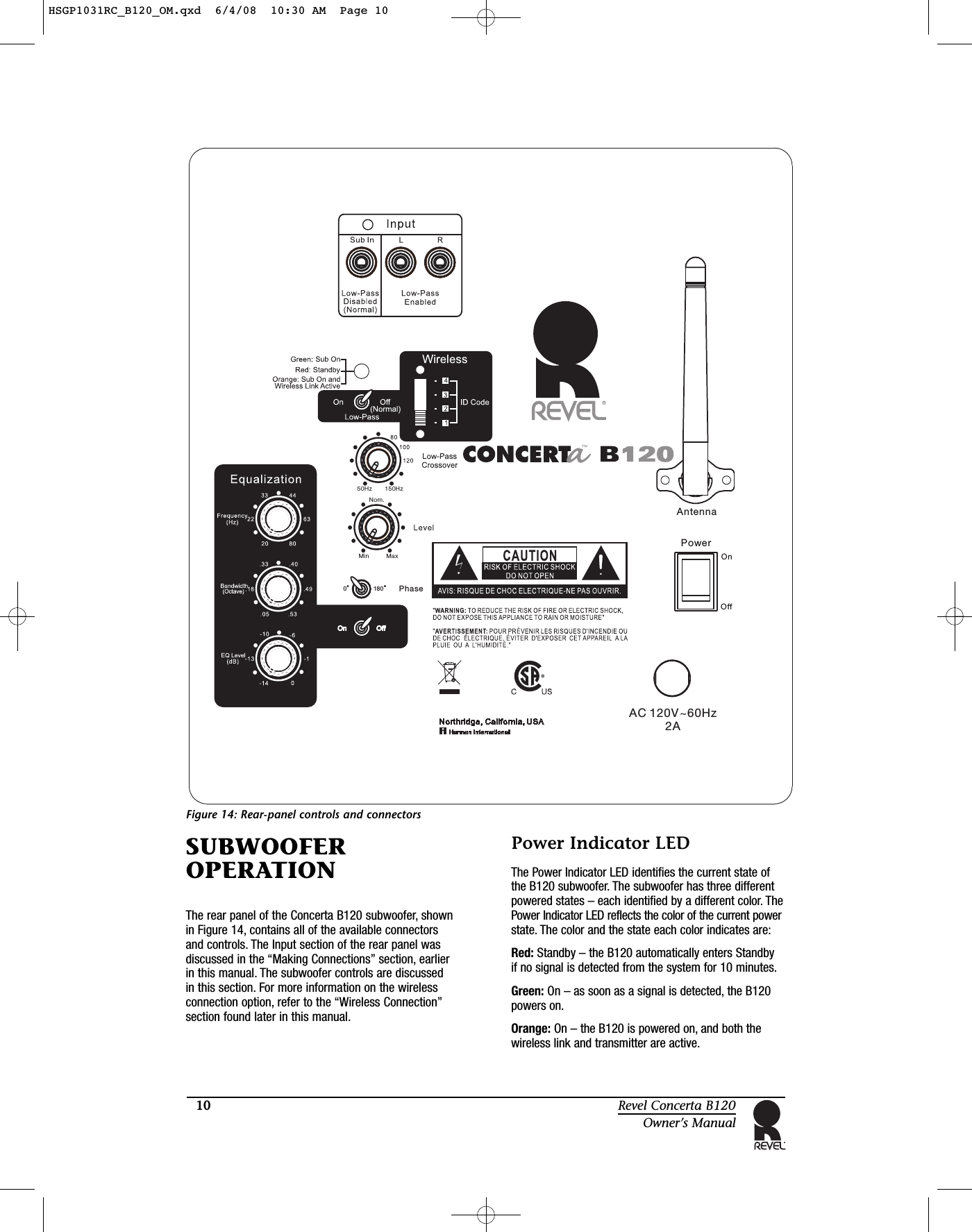
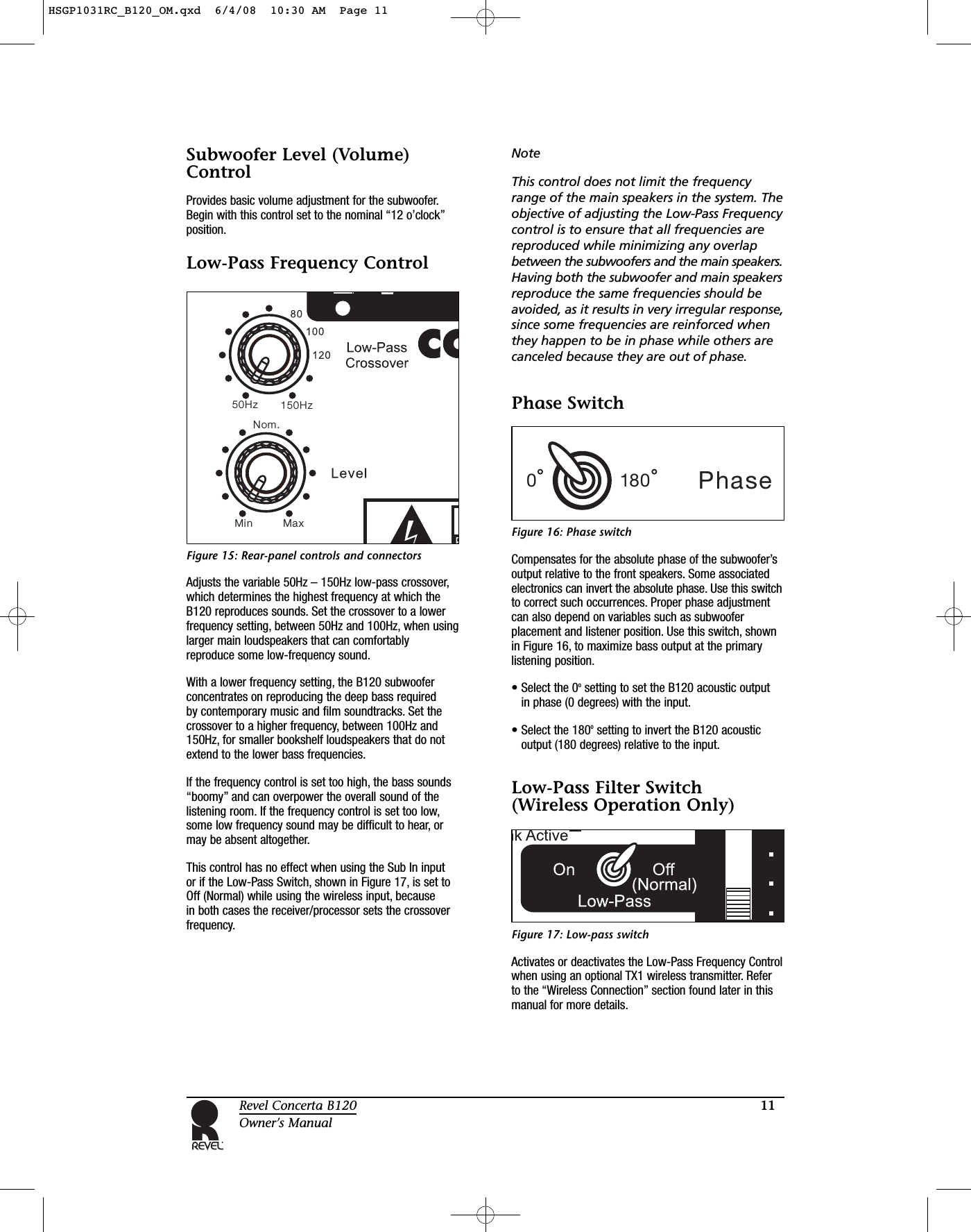
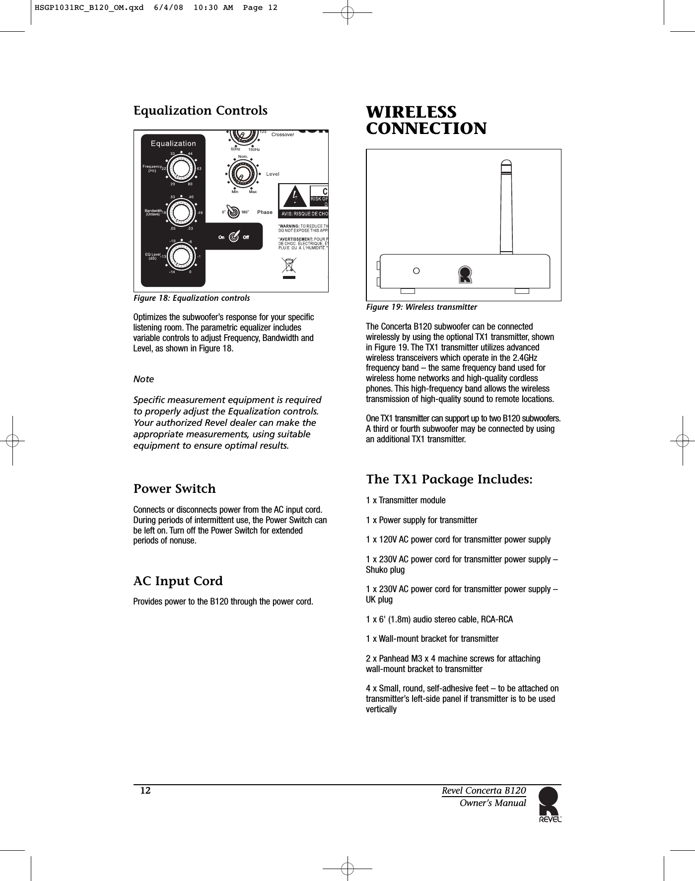
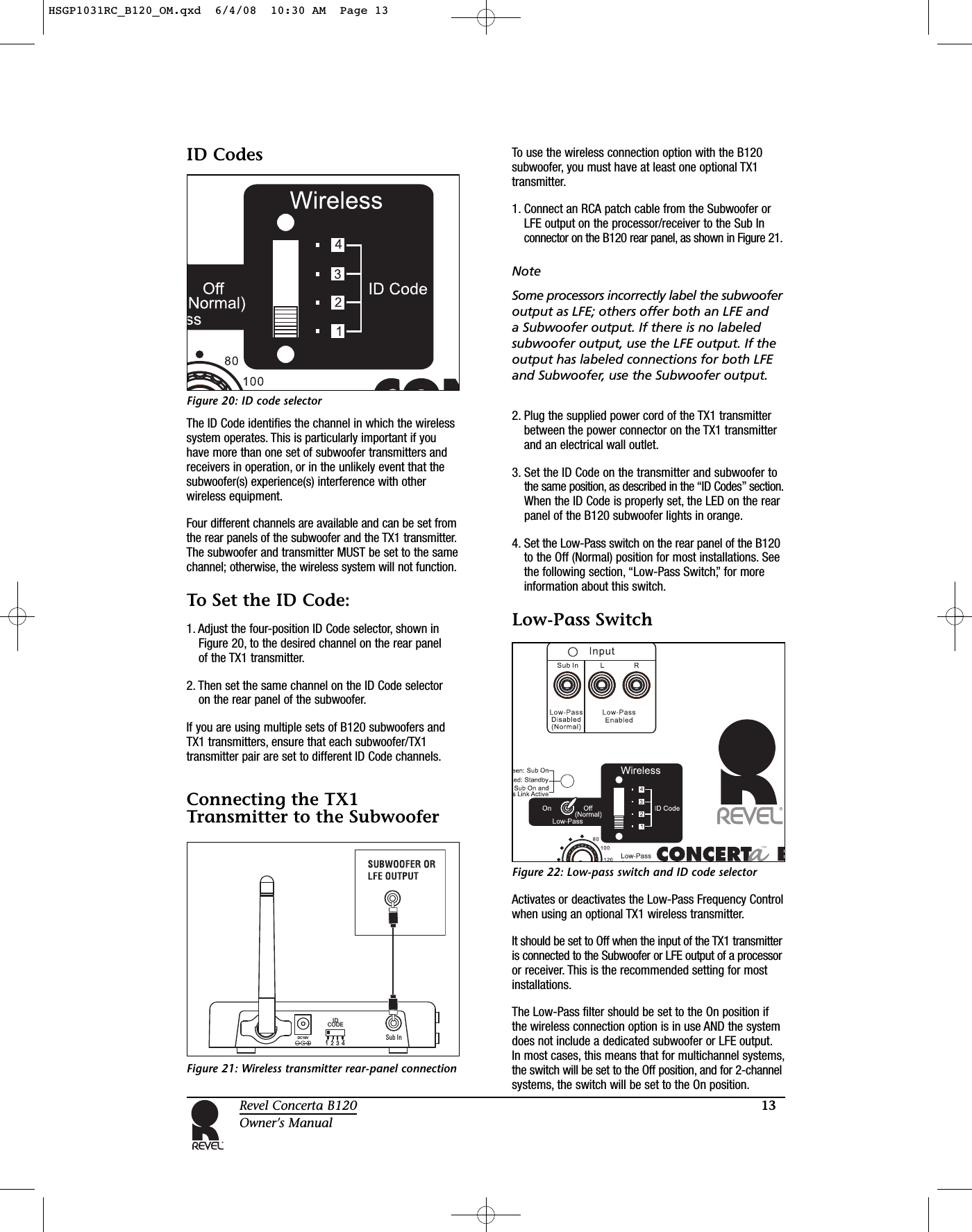
MEILOON SUB-TX Wireless Subwoofer Transmitter User Manual HSGP1031RC B120 OM

Meiloon Industrial Co., Ltd. Wireless Subwoofer Transmitter HSGP1031RC B120 OM

Users Manual

Revel®B120 SubwooferOwner’s Manual(120V)HSGP1031RC_B120_OM.qxd  6/4/08  10:30 AM  Page 1
2Revel Concerta B120Owner’s ManualThis equipment has been tested and found to comply with thelimits for a Class B digital device, pursuant to Part 15 of the FCCRules. These limits are designed to provide reasonable protectionagainst harmful interference in a residential installation.This equipment generates, uses and can radiate radio frequencyenergy and, if not installed and used in accordance with theinstructions, may cause harmful interference to radiocommunications. However, there is no guarantee that interferencewill not occur in a particular installation. If this equipment doescause harmful interference to radio or television reception, whichcan be determined by turning the equipment off and on, the user isencouraged to try to correct the interference by one of thefollowing measures:• Reorient or relocate the receiving antenna.• Increase the separation between the equipment and receiver.• Connect the equipment into an outlet on a circuit different fromthat to which the receiver is connected.• Consult the dealer or an experienced radio/TV technician for help.FCC Caution: To assure continued compliance, any changes or modifications not expressly approved by the party responsiblefor compliance could void the user’s authority to operate thisequipment. (Example – use only shielded interface cables whenconnecting to computer or peripheral devices.)FCC Radiation Exposure StatementThis equipment complies with FCC RF radiation exposure limits setforth for an uncontrolled environment. This equipment should beinstalled and operated with a minimum distance of 20 centimetersbetween the radiator and your body.This device complies with Part 15 of the FCC Rules. Operation issubject to the following two conditions:1. This device may not cause harmful interference, and 2. This device must accept any interference received, includinginterference that may cause undesired operation.IMPORTANT SAFETY PRECAUTIONS READ FIRST!FEDERAL COMMUNICATIONS COMMISSIONINTERFERENCE STATEMENT1. Read these instructions.2. Keep these instructions.3. Heed all warnings.4. Follow all instructions.5. Do not use this apparatus near water.6. Clean only with a dry cloth.7. Do not block any ventilation openings. Install in accordance with the manufacturer’s instructions.8. Do not install near any heat sources such as radiators, heatregisters, stoves or other apparatus (including amplifiers) thatproduce heat.9. Do not defeat the safety purpose of the polarized orgrounding-type plug. A polarized plug has two blades withone wider than the other. A grounding-type plug has twoblades and a third grounding prong. The wide blade or thethird prong is provided for your safety. If the provided plugdoes not fit into your outlet, consult an electrician forreplacement of the obsolete outlet.10. Protect the power cord from being walked on or pinched,particularly at plugs, convenience receptacles and the pointwhere they exit from the apparatus.11.   Only use attachments/accessories specified by themanufacturer.12. Use only with the cart, stand, tripod, bracketor table specified by the manufacturer orsold with the apparatus. When a cart isused, use caution when moving thecart/apparatus combination to avoid injuryfrom tip-over.13. Unplug this apparatus during lightning storms or whenunused for long periods of time.14. Refer all servicing to qualified service personnel. Servicing isrequired when the apparatus has been damaged in any way,such as power supply cord or plug is damaged, liquid hasbeen spilled or objects have fallen into the apparatus, or theapparatus has been exposed to rain or moisture, does notoperate normally or has been dropped.15. Do not expose this apparatus to dripping or splashing andensure that no objects filled with liquids, such as vases, areplaced on the apparatus.16. To completely disconnect this apparatus from the AC Mains,disconnect the power supply cord plug from the ACreceptacle.17. The mains plug of the power supply cord shall remain readilyoperable.18. Do not expose batteries to excessive heat such as sunshine,fire or the like.The lightning flash with arrowhead symbol, withinan equilateral triangle, is intended to alert theuser to the presence of uninsulated “dangerousvoltage” within the product’s enclosure that maybe of sufficient magnitude to constitute a risk ofelectric shock to persons.The exclamation point within an equilateraltriangle is intended to alert the user to thepresence of important operating and maintenance(servicing) instructions in the literatureaccompanying the product.WARNING: To reduce the risk of fire or electricshock, do not expose this apparatus to rain ormoisture.HSGP1031RC_B120_OM.qxd  6/4/08  10:30 AM  Page 2
3Revel Concerta B120Owner’s ManualABOUT THE REVEL®CONCERTA™B120SUBWOOFERThank you for purchasing the Revel Concerta B120,a high-performance powered subwoofer that perfectlyaugments Revel Concerta Series loudspeakers in stereomusic or home theater entertainment systems. The B120’sadjustable controls and multiple connection options alsoallow you to optimize the subwoofer’s performance inany system and listening room.Featuring a 12" (305mm) woofer with 1-1/2" (38.1mm)peak-to-peak excursion and powered by a 250-wattamplifier, the B120 subwoofer reproduces deep, realisticbass with very low distortion, even at the lowestfrequencies and high output levels.Combining superior form and function, the B120’sproprietary woofer is constructed with an anodized-aluminum diaphragm for great strength at high outputlevels. The spider incorporates a superior-strengthNomex®/cotton blend with optimized geometry forincreased linearity. The motor includes a large ceramic-magnet motor system. A 2" (50.8mm) copper voice coilis wound on a Kapton®bobbin for impressive powerhandling and freedom from compression. The ventedcenter pole facilitates heat dissipation, allowing moreefficient high-power handling and low compression.The B120 cabinet consists of medium-density fiberboard(MDF) walls and extensive internal bracing to reducecabinet-induced colorations. Rubber padded feet areattached to the bottom of the cabinet for optimal stability,accommodating installations on any floor surface.Since 1996, the Revel brand has been at the forefront ofloudspeaker design. Backed by Harman International’sextensive research and design facilities, Revel ConcertaSeries speakers benefit from cutting-edge developmenttools, such as:•A multichannel listening lab allows for double-blindlistening tests.•A laser interferometer enables detailed driver andcabinet analysis.•Multiple large anechoic chambers provide forprecise tests and measurements.•Finite-element analysis allows for advancedloudspeaker modeling.•A stereo lithography apparatus aids in achievingtight tolerances.Adding to the proud lineage of Revel Ultima™and Performa™Series loudspeakers, the Concerta B120 subwoofer furthersubstantiates the Revel reputation for high-quality, high-performance loudspeakers and subwoofers.B120 HIGHLIGHTS•High-output capability with low distortion•Proprietary 12" (305mm) anodized-aluminumdiaphragm woofer•Built-in 250W RMS amplifier•Line-level RCA inputs•Advanced woofer motor structure•Large voice coil for wide dynamic range withoutcompression•Phase switch•Low-pass frequency control•Low-frequency level control•Parametric room equalization controls•Elegant cabinet design with vinyl finishes•Wireless operation (with optional TX1 transmitter)PRODUCT REGISTRATIONImportant!Please register your Concerta B120 subwoofer online atwww.revelspeakers.com within 15 days of purchase.Retain the original, dated sales receipt as proof ofwarranty coverage.UNPACKINGThe Concerta B120 subwoofer requires special care andhandling during unpacking. Pay particular attention tothe precautions that appear in this section andthroughout this owner’s manual.Warning!Do not attempt to lift or move the B120 alone. Properlifting requires at least two strong adults. When liftingthe B120, stand as straight as possible, using the legmuscles to lift. Do not attempt to lift the B120 whilebending at the waist. When moving the B120, rock itside to side into the desired position. Failure to followthese procedures may result in personal injuries and/orproduct damage.Save all packaging materials for possible future shippingneeds. Refer to the “Limited Warranty” section foundlater in this manual for more information.HSGP1031RC_B120_OM.qxd  6/4/08  10:30 AM  Page 3
4Revel Concerta B120Owner’s ManualTo Unpack the B120: Figure 1: Unpacking the B120 subwoofer1. Place the packing carton upright and fully open thetop flaps. Refer to Figure 1.2. Without allowing the top flaps to close, stand the packingcarton upside down by carefully “rolling” the cartonover on a soft surface, such as carpet.3. Lift the packing carton off of the subwoofer. Usecaution to avoid damaging the cabinet and objectslocated above the packing carton.4. In addition to what is shown in Figure 1 above,the following is included with each B120:1 x 15' (4.6m) single-RCA LFE cableSUBWOOFERPLACEMENTBelow 300Hz, loudspeaker and listener locations have a profound impact on the way sound is reproduced.All rooms have “standing waves,” by which certainfrequencies are emphasized or diminished. Theircomplex patterns can combine to introduce tremendoussound coloration at low frequencies.The Concerta B120’s Equalization controls can help tocompensate for these effects, but no electronic systemalone can fully compensate for the dramatic effects ofroom acoustics. Every room has locations where “nulls”at specific frequencies occur. These cancellations of thesound are like “black holes,” which no amount ofequalization can fill. The best results are alwaysachieved through careful placement of both theloudspeakers and the listening position. Preferableplacement can be determined through the use ofcomputer modeling programs, or by trial-and-errormeasurements. For optimal results, find the bestloudspeaker and listener locations first, then use theB120 Equalization controls for fine-tune adjustments.To help determine good locations for the subwoofer(s)and the listener(s), it is recommended that you makehigh-resolution in-room response measurements. Yourauthorized Revel dealer can make the appropriatemeasurements, using suitable equipment to ensureoptimal results.NoteMany sound-measurement devices are notaccurate enough to properly measure low-frequency performance in a listeningroom, since room boundaries can oftencause modes (standing waves) with verynarrow-band peaks and dips. Check withyour authorized Revel dealer to confirmthat your measurement equipment issuitable for accurate, high-resolutionmeasurements.OMtop-EPEsubwooferplastic bag bottom-EPE grillebeauty carton  HSGP1031RC_B120_OM.qxd  6/4/08  10:30 AM  Page 4
5Revel Concerta B120Owner’s ManualGENERAL PLACEMENTGUIDELINESThe following placement suggestions are followed bydiagrams for recommended subwoofer locations. Due to thenature of room acoustics, the best approach is to experimentwith different listening locations, as well as loudspeakerlocations, to obtain the best sound at low frequencies.Generally, it’s best to place the Revel Concerta B120subwoofer(s) near solid walls to reinforce bass response.Avoid placing the subwoofer(s) near windows, which canrattle and transmit sound to the outside world. Placing asubwoofer in the corner of a room, as shown in Figure 2,results in maximum reinforcement, which contributes tolower distortion. Most dips cannot be equalized, but theycan be minimized through the optimal placement of thesubwoofer(s) and listening position.Figure 2: Single B120 subwooferPlacing two Revel Concerta B120 subwoofers in oppositecorners of the listening room, as shown in Figure 3,results in smoother low-frequency response and moreconsistent sound throughout the listening area.Figure 3: Two B120 subwoofers in opposite corners If using two B120 subwoofers but corner placement isnot an option, try placing the subwoofers at the midpointsof opposite walls, as shown in Figures 4 and 4a.Figure 4: Two B120 subwoofers at opposite walls Figure 4a: Two B120 subwoofers at opposite walls Use of a modeling program or trial-and-error measurementsto further determine the best locations is recommended.Using precise measurements to determine subwooferplacement minimizes the response dips due to standing-wave cancellation that cannot be corrected by equal-ization. Ask your authorized Revel dealer for moreinformation and assistance.B120B120B120B120B120B120B120HSGP1031RC_B120_OM.qxd  6/4/08  10:30 AM  Page 5
6Revel Concerta B120Owner’s ManualFor large rooms (greater than 2000 to 3000 cubic feet,or 57 to 85 cubic meters), consider adding one or moreadditional B120 subwoofers for greater bass output andlower distortion.Four properly placed Concerta B120 subwoofers achieve the smoothest low-frequency response with the most consistent sound throughout the listening area. When using four B120s, the flattest response isusually obtained by placing one pair at the midway pointof the opposite front and back walls, and a second pairat the midway points of the side walls, as shown inFigure 5. Your authorized Revel dealer can use in-roommeasurements to fine-tune the locations, accounting for variation in construction among the room walls.Figure 5: Four B120 subwoofers at midpoints Another option is to place four Concerta B120 subwoofersin the corners of the listening room, as shown in Figure 6.Figure 6: Four B120 subwoofers in the corners A third alternative is to place the four B120s on the frontand back walls at one-third of the distance into the room,as shown in Figure 7.Figure 7: Four B120 subwoofers at the front and back The placement of the other system loudspeakers in thelistening room also affects the way sound (below 300Hz)is reproduced. Just as you would for the subwoofers,use a modeling program or trial-and-error measurementsto determine the best locations.Since listening and speaker locations are equally important,the trial-and-error process can be time-consuming.However, the sonic rewards are well worth the timespent determining the ideal placement locations.Remember that peaks (below the subwoofer crossoverfrequency) can be minimized or eliminated by theproper adjustment of the Concerta B120’s Equalizationcontrols, but dips cannot be corrected via equalization.Therefore, the most important objective is to findlocations that result in the minimum number (andseverity) of dips. Contact your authorized Revel dealerfor assistance in determining the proper placement ofyour Revel loudspeakers and subwoofers.After placing the B120 subwoofer(s), begin playback of a familiar music or film source that has substantial basscontent. Listen from the primary listening position, increasingthe overall volume of the system to a comfortable level.Adjust the Subwoofer Level (volume) control until youobtain the desired blend of bass. Also, test the subwooferlevel by playing a recording of a deep male voice. Settingthe subwoofer level (or crossover frequency) too highresults in unnaturally “thick” or “boomy” vocal reproduction.Bass response should not overpower the room, andshould be adjusted to achieve a harmonious blendacross the entire audible range.If you are using a multichannel receiver or processorwith a subwoofer output, it’s preferable to use theSubwoofer Level adjustment on the processor. Set theB120 Level control to the indicated “Nominal” position.B120B120B120B120B120B120B120B120B120 B120B120 B120HSGP1031RC_B120_OM.qxd  6/4/08  10:30 AM  Page 6
7Revel Concerta B120Owner’s ManualNoteSetting the level of the subwoofer in relationto the left and right front speakers is of criticalimportance because it is essential that thesubwoofer integrate smoothly with the entiresystem. Setting the level too high results in an overpowering bass response. Setting thelevel too low negates the benefits of theB120 subwoofer.MAKINGCONNECTIONSCAUTION!Never make or breakconnections unless all systemcomponents are powered off.Figure 8: Rear-panel input connectors This section provides typical examples of cableconnections with different system configurations anddevices. Review the owner’s manuals for associatedaudio components to determine their connectionrequirements.The B120 subwoofer input connectors are located on therear panel. Two gold-plated RCA connector options areavailable – Sub In Low-Pass Disabled (Normal) and L/RLow-Pass Enabled – as shown in Figure 8.In most cases, you’ll use the Sub In connector, as it’sdesigned for multichannel use. This input bypasses thelow-pass filter, and is the appropriate input for mostinstallations. This connector should be used when thereis a dedicated subwoofer output available on the audioprocessor or receiver.NoteSome processors incorrectly label the subwooferoutput as LFE; others offer both an LFE and a Subwoofer output. If there is no labeledsubwoofer output, use the LFE output. If theoutput has labeled connections for both LFEand Subwoofer, use the Subwoofer output.The L (Left) and R (Right) connectors on the rear panel of the B120 are for use with 2-channel applications, where there is nodedicated subwoofer output available. Theseinputs are automatically crossed-over by theadjustable Low-Pass Crossover control on therear panel. Having the low-pass filter enabledhelps offset the fact that most 2-channelsystems do not perform any high-pass filteringon the main speakers, minimizing theadvantages of using a subwoofer. Theseconnectors should be used in 2-channelapplications where the receiver or preamplifierlacks a dedicated subwoofer or LFE output.NoteThe Concerta B120 subwoofer has a thirdconnection option – wireless connection isalso available when coupled with the optionalTX1 transmitter. Refer to the “WirelessConnection” section found later in this manualfor additional details regarding this option.Multichannel Applications –Typical ConnectionFigure 9: Typical connection This configuration is for use with multichannelprocessors or receivers that have a single dedicatedSubwoofer or LFE output connector.Connect the supplied RCA patch cable from the Subwooferor LFE output on the processor/receiver to the Sub Inconnector on the B120 rear panel, as shown in Figure 9.B120 Input PanelReceiver/ProcessorSubwooferOutputHSGP1031RC_B120_OM.qxd  6/4/08  10:30 AM  Page 7
8Revel Concerta B120Owner’s Manual2-Channel Applications –Connecting to the Main OutputsFigure 10: Connection to main outputsThis configuration is for use with 2-channel preamplifier/power amplifier combinations or 2-channel receiversthat have full-range outputs for the left and right channels.The internal low-pass filter in the B120 is used to limitfrequency range of the subwoofer, preventing undesirableoverlap with the main loudspeakers.1. Connect an RCA patch cable between the left mainoutput on the receiver/preamplifier to the L(eft) Low-Pass Enabled connector on the B120 rear panel,as shown in Figure 10.2. Connect an RCA patch cable between the right mainoutput on the receiver/preamplifier to the R(ight) Low-Pass Enabled connector on the B120 rear panel.NoteThis configuration applies to receivers withpreamplifier outputs or to preamplifier/power amplifier configurations in which thereare two sets of Main outputs. If the receiverhas jumpers from the Pre- or Main-Out to theAmp in connectors or if the preamplifier hasonly one set of Main-Out connectors, a Y-adapter should be used to send the samesignal to both the main power amplifier andthe subwoofer(s). Tape Out or Record Outconnectors cannot be used.Multichannel Applications –Multiple Subwoofer ConnectionsFigure 11: Connection to multiple B120 subwoofersThis configuration is for use with multiple B120 subwoofersand a multichannel processor or receiver.NoteThe supplied single-RCA patch cord can beused in any of the three connections describedbelow, but you will need to purchase an RCA Y-adapter and possibly an additionalsingle-RCA cable.1. Connect an RCA patch cable from the Subwoofer orLFE output on the processor/receiver to the singleinput on the Y-adapter, as shown in Figure 11.2. Connect an RCA patch cable from one of the outputsof the Y-adapter to the Sub In connector on the firstB120 rear panel.3. Connect an RCA patch cable from the second outputof the Y-adapter to the Sub In connector on thesecond B120 rear panel.NoteAdditional B120 subwoofers may be connectedby using additional Y-adapters – by placing an additional Y-adapter input connector intoone of the output connectors of the first Y-adapter.B120 Input PanelReceiver/PreamplifierMainOutputsMainOutputsB120 Input PanelSub 2B120 Input PanelSub 1Receiver/ProcessorSubwooferOutputHSGP1031RC_B120_OM.qxd  6/4/08  10:30 AM  Page 8
9Revel Concerta B120Owner’s ManualMultichannel Applications –Multiple Subwoofer OutputsWith a Single SubwooferFigure 12: Typical connection with multiplesubwoofer outputsThis configuration is for use with multichannelprocessors or receivers that have more than onededicated Subwoofer or LFE output connector.1. Set the processor or receiver to “Mono Subwoofer.”2. Connect the supplied RCA patch cable from one of theSubwoofer or LFE outputs on the processor/receiver tothe Sub In connector on the B120 rear panel, as shownin Figure 12.NoteAdditional B120 subwoofers may be connectedby using additional Y-adapters – place the Y-adapter(s) in the processor/receiver Subwooferor LFE output connector(s). Then connect theB120 Sub In connectors to the outputs of theY-adapters.Multichannel Applications –Multiple Subwoofer Outputsand Multiple SubwoofersFigure 13: Multiple subwoofer connectionsThis configuration is for use with multiple B120subwoofers and a multichannel processor or receiverthat has more than one dedicated Subwoofer or LFEoutput connector.1. Set the processor or receiver to “Mono Subwoofer.”2. Connect the supplied RCA patch cable from one of theSubwoofer or LFE outputs on the processor/receiver tothe Sub In connector on the first B120 rear panel, asshown in Figure 13.3. Connect the RCA patch cable that was supplied with thesecond B120, from the second Subwoofer or LFE outputon the processor/receiver to the Sub In connector onthe second B120 rear panel.NoteAdditional B120 subwoofers may be connectedby using additional Y-adapters – place the Y-adapter(s) in the processor/receiver Subwooferor LFE output connector(s). Then connect theB120 Sub In connectors to the outputs of theY-adapters.B120 Input PanelReceiver/ProcessorSubwooferOutputSubwooferOutputB120 Input PanelSub 2B120 Input PanelSub 1Receiver/ProcessorSubwooferOutputSubwooferOutputHSGP1031RC_B120_OM.qxd  6/4/08  10:30 AM  Page 9
10 Revel Concerta B120Owner’s ManualFigure 14: Rear-panel controls and connectorsSUBWOOFEROPERATIONThe rear panel of the Concerta B120 subwoofer, shownin Figure 14, contains all of the available connectorsand controls. The Input section of the rear panel wasdiscussed in the “Making Connections” section, earlierin this manual. The subwoofer controls are discussed in this section. For more information on the wirelessconnection option, refer to the “Wireless Connection”section found later in this manual.Power Indicator LEDThe Power Indicator LED identifies the current state ofthe B120 subwoofer. The subwoofer has three differentpowered states – each identified by a different color. ThePower Indicator LED reflects the color of the current powerstate. The color and the state each color indicates are:Red: Standby – the B120 automatically enters Standby if no signal is detected from the system for 10 minutes.Green: On – as soon as a signal is detected, the B120powers on.Orange: On – the B120 is powered on, and both thewireless link and transmitter are active.AC 120V~60Hz           2AOnOffPowerAntennaPhase150 zH50HzNom.Min Max0180HSGP1031RC_B120_OM.qxd  6/4/08  10:30 AM  Page 10
11Revel Concerta B120Owner’s ManualSubwoofer Level (Volume)ControlProvides basic volume adjustment for the subwoofer.Begin with this control set to the nominal “12 o’clock”position.Low-Pass Frequency ControlFigure 15: Rear-panel controls and connectorsAdjusts the variable 50Hz – 150Hz low-pass crossover,which determines the highest frequency at which theB120 reproduces sounds. Set the crossover to a lowerfrequency setting, between 50Hz and 100Hz, when usinglarger main loudspeakers that can comfortablyreproduce some low-frequency sound.With a lower frequency setting, the B120 subwooferconcentrates on reproducing the deep bass required by contemporary music and film soundtracks. Set thecrossover to a higher frequency, between 100Hz and150Hz, for smaller bookshelf loudspeakers that do notextend to the lower bass frequencies.If the frequency control is set too high, the bass sounds“boomy” and can overpower the overall sound of thelistening room. If the frequency control is set too low,some low frequency sound may be difficult to hear, ormay be absent altogether.This control has no effect when using the Sub In input or if the Low-Pass Switch, shown in Figure 17, is set toOff (Normal) while using the wireless input, because in both cases the receiver/processor sets the crossoverfrequency.NoteThis control does not limit the frequencyrange of the main speakers in the system. Theobjective of adjusting the Low-Pass Frequencycontrol is to ensure that all frequencies arereproduced while minimizing any overlapbetween the subwoofers and the main speakers.Having both the subwoofer and main speakersreproduce the same frequencies should beavoided, as it results in very irregular response,since some frequencies are reinforced whenthey happen to be in phase while others arecanceled because they are out of phase.Phase SwitchFigure 16: Phase switchCompensates for the absolute phase of the subwoofer’soutput relative to the front speakers. Some associatedelectronics can invert the absolute phase. Use this switchto correct such occurrences. Proper phase adjustmentcan also depend on variables such as subwooferplacement and listener position. Use this switch, shownin Figure 16, to maximize bass output at the primarylistening position.• Select the 0osetting to set the B120 acoustic output in phase (0 degrees) with the input.• Select the 180osetting to invert the B120 acousticoutput (180 degrees) relative to the input.Low-Pass Filter Switch (Wireless Operation Only)Figure 17: Low-pass switchActivates or deactivates the Low-Pass Frequency Controlwhen using an optional TX1 wireless transmitter. Refer to the “Wireless Connection” section found later in thismanual for more details.150 zH50HzNom.Min MaxPhase0180HSGP1031RC_B120_OM.qxd  6/4/08  10:30 AM  Page 11
12 Revel Concerta B120Owner’s ManualEqualization ControlsFigure 18: Equalization controlsOptimizes the subwoofer’s response for your specificlistening room. The parametric equalizer includesvariable controls to adjust Frequency, Bandwidth andLevel, as shown in Figure 18.NoteSpecific measurement equipment is requiredto properly adjust the Equalization controls.Your authorized Revel dealer can make theappropriate measurements, using suitableequipment to ensure optimal results. Power SwitchConnects or disconnects power from the AC input cord.During periods of intermittent use, the Power Switch canbe left on. Turn off the Power Switch for extendedperiods of nonuse.AC Input CordProvides power to the B120 through the power cord.WIRELESSCONNECTIONFigure 19: Wireless transmitterThe Concerta B120 subwoofer can be connectedwirelessly by using the optional TX1 transmitter, shownin Figure 19. The TX1 transmitter utilizes advancedwireless transceivers which operate in the 2.4GHzfrequency band – the same frequency band used forwireless home networks and high-quality cordlessphones. This high-frequency band allows the wirelesstransmission of high-quality sound to remote locations.One TX1 transmitter can support up to two B120 subwoofers.A third or fourth subwoofer may be connected by usingan additional TX1 transmitter.The TX1 Package Includes:1 x Transmitter module1 x Power supply for transmitter1 x 120V AC power cord for transmitter power supply1 x 230V AC power cord for transmitter power supply –Shuko plug1 x 230V AC power cord for transmitter power supply –UK plug1 x 6' (1.8m) audio stereo cable, RCA-RCA1 x Wall-mount bracket for transmitter2 x Panhead M3 x 4 machine screws for attaching wall-mount bracket to transmitter4 x Small, round, self-adhesive feet – to be attached ontransmitter’s left-side panel if transmitter is to be usedverticallyPhase150 zH50HzNom.Min Max0180HSGP1031RC_B120_OM.qxd  6/4/08  10:30 AM  Page 12
13Revel Concerta B120Owner’s ManualID CodesFigure 20: ID code selectorThe ID Code identifies the channel in which the wirelesssystem operates. This is particularly important if youhave more than one set of subwoofer transmitters andreceivers in operation, or in the unlikely event that thesubwoofer(s) experience(s) interference with otherwireless equipment.Four different channels are available and can be set fromthe rear panels of the subwoofer and the TX1 transmitter.The subwoofer and transmitter MUST be set to the samechannel; otherwise, the wireless system will not function.To Set the ID Code:1. Adjust the four-position ID Code selector, shown inFigure 20, to the desired channel on the rear panel of the TX1 transmitter.2. Then set the same channel on the ID Code selector on the rear panel of the subwoofer.If you are using multiple sets of B120 subwoofers andTX1 transmitters, ensure that each subwoofer/TX1transmitter pair are set to different ID Code channels.Connecting the TX1Transmitter to the SubwooferFigure 21: Wireless transmitter rear-panel connectionTo use the wireless connection option with the B120subwoofer, you must have at least one optional TX1transmitter.1. Connect an RCA patch cable from the Subwoofer orLFE output on the processor/receiver to the Sub Inconnector on the B120 rear panel, as shown in Figure 21.NoteSome processors incorrectly label the subwooferoutput as LFE; others offer both an LFE and a Subwoofer output. If there is no labeledsubwoofer output, use the LFE output. If theoutput has labeled connections for both LFEand Subwoofer, use the Subwoofer output.2. Plug the supplied power cord of the TX1 transmitterbetween the power connector on the TX1 transmitterand an electrical wall outlet.3. Set the ID Code on the transmitter and subwoofer to the same position, as described in the “ID Codes” section.When the ID Code is properly set, the LED on the rearpanel of the B120 subwoofer lights in orange.4. Set the Low-Pass switch on the rear panel of the B120to the Off (Normal) position for most installations. Seethe following section, “Low-Pass Switch,” for moreinformation about this switch.Low-Pass SwitchFigure 22: Low-pass switch and ID code selectorActivates or deactivates the Low-Pass Frequency Controlwhen using an optional TX1 wireless transmitter.It should be set to Off when the input of the TX1 transmitteris connected to the Subwoofer or LFE output of a processoror receiver. This is the recommended setting for mostinstallations.The Low-Pass filter should be set to the On position ifthe wireless connection option is in use AND the systemdoes not include a dedicated subwoofer or LFE output.In most cases, this means that for multichannel systems,the switch will be set to the Off position, and for 2-channelsystems, the switch will be set to the On position.Sub InIDCODEDC18V1234HSGP1031RC_B120_OM.qxd  6/4/08  10:30 AM  Page 13
14 Revel Concerta B120Owner’s ManualWall-Mounting the Transmitter ModuleStep 1. Insert the two M3 x 4 machine screws throughthe wall bracket and into the rear of the transmittermodule, as shown.Step 2. Attach the transmitter module with wall bracketto the wall, using suitable hardware (and wallanchors, if necessary).LIMITED WARRANTYA valid serial number is required for warranty coverage.This Revel warranty protects the original retail purchaserfor a period of five (5) years (parts and labor) from anyfailure as a result of original manufacturing defects,so long as:1. The Revel products were purchased within the 50 United States, its territories, or Canada.2. The dealer from whom the Revel products werepurchased was authorized to sell such products at the time of the original purchase.3. The original, dated Bill of Sale is presented wheneverservice is required during the warranty period.The balance of this warranty is transferable only if theused product is purchased from an authorized Reveldealer. This warranty is only valid for service within theUnited States, its territories, and Canada; please contactan authorized Revel dealer for warranty and serviceinformation.Any Revel product not performing satisfactorily may be returned to the factory for evaluation. Returnauthorization must first be obtained by either calling orwriting Customer Service prior to shipping the product.The customer is responsible for shipping charges to the factory. Customer Service will pay return shippingcharges within the United States only in the event thatthe product is found to be defective, as mentionedabove. There are other stipulations that may apply to shipping charges.There is no other express warranty on this product.Neither this warranty nor any other warranty, express orimplied, including implied warranties of merchantabilityand fitness, shall extend beyond the warranty period.No responsibility is assumed for any incidental orconsequential damages, so that the above exclusion or limitation may not apply.This warranty provides specific legal rights. Other statesmay provide additional rights. This warranty is applicablein the United States, its territories, and Canada. Outside of the United States, its territories, and Canada, pleasecontact an authorized Revel dealer for warranty andservice information.The information this documentcontains is subject to change without notice. In the eventthat there are differences between this warranty and theprovisions of any advertisements, documentation, productbrochures or packaging cartons, the terms of thiswarranty will prevail.For customer service and product shipment information,refer to www.revelspeakers.com.ROUTINE CARE &MAINTENANCEThe B120 cabinet’s finish does not require routinemaintenance. However, cabinet surfaces that have been marked with fingerprints, dust or other dirt can be cleaned using a soft cloth. Do not use any cleaningproducts or polishes on the cabinet or grille.CAUTION!To prevent cabinet damage, DO NOT use a cloth madewith steel wool or use metal polish to clean the cabinet.HSGP1031RC_B120_OM.qxd  6/4/08  10:30 AM  Page 14
15Revel Concerta B120Owner’s ManualB120 SubwooferFrequency Response +/–0.5dB in the pass-bandLow Frequency –3dB at 36HzExtension (Anechoic) –6dB at 32Hz–10dB at 29Hz Maximum Amplifier Output 20Hz – 150Hz with no more than 0.1% THD,250W RMS, 300 dynamicLow-Pass Crossover Frequencies 50Hz – 150Hz, 24dB/octave, continuously variablePower Requirements 120V AC @ 60Hz, 2AHeight 17-3/4" (45.0cm), including feetWidth 15-3/4" (40.0cm)Depth 14" (35.6cm) with grilleWeight 51 lb (23.15kg)Features, specifications and appearance are subject to change without notice.SPECIFICATIONS NOTESHSGP1031RC_B120_OM.qxd  6/4/08  10:30 AM  Page 15
For customer service and product shipment information,refer to www.revelspeakers.com.Part No. 406-000-05850-E©2008 Harman International Industries, Incorporated.All rights reserved.Revel, the Revel logo, Ultima, Performa and Concerta aretrademarks of Harman International Industries, Incorporated,in the United States and/or other countries.Nomex and Kapton are registered trademarks of E.I. du Pont de Nemours and Company.This document should not be construed as a commitmenton the part of Harman International Industries, Incorporated.The information it contains is subject to change withoutnotice. Harman International Industries, Incorporated,assumes no responsibility for errors that may appearwithin this document.HSGP1031RC_B120_OM.qxd  6/4/08  10:30 AM  Page 16

Navigation menu