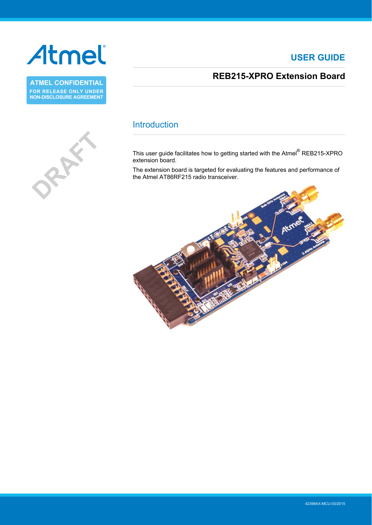
MICROCHIP TECHNOLOGY A091982 ATREB215-XPRO User Manual REB215 XPRO Extension Board USER GUIDE
Atmel Norway AS ATREB215-XPRO REB215 XPRO Extension Board USER GUIDE
UserManual.wiki
>
MICROCHIP TECHNOLOGY
>
A091982 User Manual
>
Users Manual
Contents
1.
Users Manual
2.
User Manual
Users Manual
Navigation menu
Upload a User Manual
Namespaces
Wiki Guide
HTML
PDF
Info
Views
User Manual
Discussion / Help
Navigation
![REB215-XPRO Extension Board [USER GUIDE]42398AX-MCU-03/20152DRAFTTable of ContentsIntroduction .................................................................................... 11. Getting Started ........................................................................ 31.1. Features .............................................................................. 31.2. Design Documentation and Related Links .................................. 31.3. Board Assembly .................................................................... 31.3.1. Connect to a Xplained Pro Board ................................. 31.3.2. In Customer Development Assembly ............................. 32. Performance Analyzer ............................................................. 42.1. Introduction .......................................................................... 42.2. Program Installation ............................................................... 42.3. Using the Performance Analyzer .............................................. 72.4. Typical Board Assembly ......................................................... 73. Xplained Pro ............................................................................ 93.1. Hardware Identification System ................................................ 93.2. Standard Headers and Connectors ........................................... 93.2.1. Xplained Pro Standard Extension Header ...................... 94. Hardware User Guide ........................................................... 114.1. Board Overview .................................................................. 114.2. Headers and Connectors ...................................................... 114.2.1. J100 Xplained Pro Extension Connector ...................... 114.2.2. J104 & J105 ........................................................... 124.2.3. Serial I/Q Data Interface (J101, J102, J103) .................. 124.2.4. Current Monitoring (J1) ............................................. 134.3. Board GUI .......................................................................... 134.3.1. LEDs ..................................................................... 134.3.2. Button ................................................................... 134.3.3. SMA Connectors ..................................................... 134.4. U2 Serial EEPROM ............................................................. 135. Persistent Memory ................................................................ 146. Agency Certifications ............................................................ 156.1. United State (FCC) .............................................................. 156.2. European Union (ETSI) ........................................................ 156.3. Canada (IC) ....................................................................... 166.4. Using Limited Modular Certified Products ................................. 167. Document Revision History ................................................... 18](https://usermanual.wiki/MICROCHIP-TECHNOLOGY/A091982.Users-Manual/User-Guide-2562507-Page-2.png)
![REB215-XPRO Extension Board [USER GUIDE]42398AX-MCU-03/20153DRAFT1. Getting Started1.1 FeaturesThe REB215 extension board is a template design for the AT86RF215.1.2 Design Documentation and Related LinksThe most recent and relevant documents and software for the REB215-Xpro extension board 1.1.3 Board AssemblyThe extension board provides wireless communication to an Xplained PRO board or to your own prototype forsoftware development and hardware verification.1.3.1 Connect to a Xplained Pro BoardThe extension board can be connected to any Xplained PRO main board using the extension header.1.3.2 In Customer Development AssemblyThe extension board can be wired into the customer prototype assembly by using an on-board connectors, allrelevant signals are available at on-board connectors.1 http://www.atmel.com/tools/reb215-xpro.aspx](https://usermanual.wiki/MICROCHIP-TECHNOLOGY/A091982.Users-Manual/User-Guide-2562507-Page-3.png)
![REB215-XPRO Extension Board [USER GUIDE]42398AX-MCU-03/20154DRAFT2. Performance Analyzer2.1 IntroductionThe Performance Analyzer Firmware with the GUI in Atmel Studio Wireless Composer Extension providesbasic functional RF tests.A quick start guide and general help is provided in Wireless Composer once started.2.2 Program InstallationHow to install Wireless Composer application, follow the steps:1. Install Atmel Studio1.2. After installing the application, launch Atmel Studio.Navigate to Tools > Extension Manager > Select Extension Manager to install Wireless ComposerSelect Wireless and Wireless Composer.1 http://www.atmel.com/tools/atmelstudio.aspx](https://usermanual.wiki/MICROCHIP-TECHNOLOGY/A091982.Users-Manual/User-Guide-2562507-Page-4.png)
![REB215-XPRO Extension Board [USER GUIDE]42398AX-MCU-03/20155DRAFTLog on to Atmel Gallery.Click download.](https://usermanual.wiki/MICROCHIP-TECHNOLOGY/A091982.Users-Manual/User-Guide-2562507-Page-5.png)
![REB215-XPRO Extension Board [USER GUIDE]42398AX-MCU-03/20156DRAFTRestart Atmel Studio, allow help to make changes and the Performance Analyzer GUI is available in theTools menu.3. If Xplained Pro board is not pre-programmed - program the board with the Performance Analyzer Firmwareavailable in the "Wireless Performance Analyzer Firmware extension" or from source code provided in ASFby using the EDBG from Atmel studio.](https://usermanual.wiki/MICROCHIP-TECHNOLOGY/A091982.Users-Manual/User-Guide-2562507-Page-6.png)
![REB215-XPRO Extension Board [USER GUIDE]42398AX-MCU-03/20157DRAFT2.3 Using the Performance AnalyzerTo get started.1. Connect the Wireless board assembly, with the Performance Analyzer FW programmed, to the PC USBconnector and power on, a COM port should now be available for the kit.2. Power on any other wireless node assemblies of similar frequency, running the Performance Analyzer FW,and use it as a reference.3. Start Performance Analyzer GUI, connect to the kit via the COM port and follow the quick start guide.2.4 Typical Board AssemblyThe Atmel SAM4L Xplained Pro Evaluation Kit with REB215-XPRO Wireless Extension board.](https://usermanual.wiki/MICROCHIP-TECHNOLOGY/A091982.Users-Manual/User-Guide-2562507-Page-7.png)
![REB215-XPRO Extension Board [USER GUIDE]42398AX-MCU-03/20158DRAFT](https://usermanual.wiki/MICROCHIP-TECHNOLOGY/A091982.Users-Manual/User-Guide-2562507-Page-8.png)
![REB215-XPRO Extension Board [USER GUIDE]42398AX-MCU-03/20159DRAFT3. Xplained ProXplained Pro is an evaluation platform that provides the complete Atmel microcontroller experience. Theplatform consists of a series of Microcontroller (MCU) boards and extension boards that are integrated withAtmel Studio, have Atmel Software Framework (ASF) drivers and demo code, support data streaming andmore. Xplained Pro MCU boards support a wide range of Xplained Pro extension boards that are connectedthrough a set of standardized headers and connectors. Each extension board has an identification (ID) chipto uniquely identify which boards are mounted on a Xplained Pro MCU board. This information is used topresent relevant user guides, application notes, datasheets, and example code through Atmel Studio. AvailableXplained Pro MCU and extension boards can be purchased in the Atmel Web Store1.3.1 Hardware Identification SystemAll Xplained Pro compatible extension boards have an Atmel ATSHA204 CryptoAuthentication™ chip mounted.This chip contains information that identifies the extension with its name and some extra data. When anXplained Pro extension board is connected to an Xplained Pro MCU board the information is read and sentto Atmel Studio. The Atmel Kits extension, installed with Atmel Studio, will give relevant information, codeexamples and links to relevant documents. Table 3-1, “Xplained Pro ID Chip Content” on page 9 shows thedata fields stored in the ID chip with example content.Table 3-1. Xplained Pro ID Chip ContentData Field Data Type Example ContentManufacturer ASCII string Atmel’\0’Product Name ASCII string Segment LCD1 Xplained Pro’\0’Product Revision ASCII string 02’\0’Product Serial Number ASCII string 1774020200000010’\0’Minimum Voltage [mV] uint16_t 3000Maximum Voltage [mV] uint16_t 3600Maximum Current [mA] uint16_t 303.2 Standard Headers and Connectors3.2.1 Xplained Pro Standard Extension HeaderAll Xplained Pro kits have one or more dual row, 20-pin, 100mil extension headers. Xplained Pro MCU boardshave male headers while Xplained Pro extensions have their female counterparts. Note that all pins are notalways connected. However, all the connected pins follow the defined pin-out described in Table 3-2, “XplainedPro Extension Header” on page 9. The extension headers can be used to connect a wide variety ofXplained Pro extensions to Xplained Pro MCU boards and to access the pins of the target MCU on XplainedPro MCU board directly.Table 3-2. Xplained Pro Extension HeaderPin Number Name Description1 ID Communication line to the ID chip on extension board.2 GND Ground.3 ADC(+) Analog to digital converter, alternatively positive part ofdifferential ADC.4 ADC(-) Analog to digital converter, alternatively negative part ofdifferential ADC.5 GPIO1 General purpose I/O.6 GPIO2 General purpose I/O.7 PWM(+) Pulse width modulation, alternatively positive part ofdifferential PWM.8 PWM(-) Pulse width modulation, alternatively positive part ofdifferential PWM.1 http://store.atmel.com/CBC.aspx?q=c:100113](https://usermanual.wiki/MICROCHIP-TECHNOLOGY/A091982.Users-Manual/User-Guide-2562507-Page-9.png)
![REB215-XPRO Extension Board [USER GUIDE]42398AX-MCU-03/201510DRAFTPin Number Name Description9 IRQ/GPIO Interrupt request line and/or general purpose I/O.10 SPI_SS_B/GPIO Slave select for SPI and/or general purpose I/O.11 TWI_SDA Data line for two-wire interface. Always implemented, bustype.12 TWI_SCL Clock line for two-wire interface. Always implemented, bustype.13 USART_RX Receiver line of Universal Synchronous and Asynchronousserial Receiver and Transmitter.14 USART_TX Transmitter line of Universal Synchronous andAsynchronous serial Receiver and Transmitter.15 SPI_SS_A Slave select for SPI. Should be unique if possible.16 SPI_MOSI Master out slave in line of Serial peripheral interface. Alwaysimplemented, bus type.17 SPI_MISO Master in slave out line of Serial peripheral interface. Alwaysimplemented, bus type.18 SPI_SCK Clock for Serial peripheral interface. Always implemented,bus type.19 GND Ground.20 VCC Power for extension board.](https://usermanual.wiki/MICROCHIP-TECHNOLOGY/A091982.Users-Manual/User-Guide-2562507-Page-10.png)
![REB215-XPRO Extension Board [USER GUIDE]42398AX-MCU-03/201511DRAFT4. Hardware User Guide4.1 Board OverviewFigure 4-1. Board overview4.2 Headers and ConnectorsThe extension board connectors.4.2.1 J100 Xplained Pro Extension ConnectorThe Xplained Pro extension connectors, used to connect the extension board to the Xplained Pro board.Table 4-1. J100 Xplained Pro Extension HeaderRF215Pin Name Pin Name Description1 ID Communication line to the ID chip on theextension board.2 GND Ground.3 ADC(+) 4 ADC(-) 5 GPIO1 LED D2 Yellow for user function.6 GPIO2 LED D1 Green for user function.7 PWM(+) 13 RSTN RESET to RF215.8 PWM(-) 9 IRQ/GPIO 40 IRQ Interrupt request line to uC on Xplained Proboard.10 SPI_SS_B/GPIO 11 TWI_SDA Data line for the two wire interface toAT24MAC602 serial EEPROM.12 TWI_SCL Clock line for the two wire interface toAT24MAC602 serial EEPROM.13 USART_RX 14 USART_TX 15 SPI_SS_A 42 SELN Slave select for SPI. Should be unique ifpossible.16 SPI_MOSI 43 MOSI Master out slave in line of Serial peripheralinterface. Always implemented, bus type.](https://usermanual.wiki/MICROCHIP-TECHNOLOGY/A091982.Users-Manual/User-Guide-2562507-Page-11.png)
![REB215-XPRO Extension Board [USER GUIDE]42398AX-MCU-03/201512DRAFTRF215Pin Name Pin Name Description17 SPI_MISO 44 MISO Master in slave out line of Serial peripheralinterface. Always implemented, bus type.18 SPI_SCK 41 SCLK Clock for Serial peripheral interface. Alwaysimplemented, bus type.19 GND Ground.20 VCC Power for extension board.4.2.2 J104 & J105J104 and J05 provide to control an external RF analog frontend device, external LNA, PA.Table 4-2. J104Pin RF215 signal Function1 FEB24 External Frontend Control for 2.4GHz.2 FEA24 External Frontend Control for 2.4GHz.Table 4-3. J105Pin RF215 signal Function1 FEB09 External Frontend Control for Sub-1GHz.J105-2 FEA09 External Frontend Control for Sub-1GHz.4.2.3 Serial I/Q Data Interface (J101, J102, J103)Low voltage differential signalling (LVDS) interface is used for the data transfer between the AT86RF215 andan external baseband processor.Table 4-4. J101- I/Q Data Receiver 2.4GHzPin RF215 signal Function1 Ground2 RXDP24 B+ (Receive)3 RXDN24 B- (Receive)4 Ground5 RXCLKP A+ (Receive)6 RXCLKN A- (Receive)7 GroundTable 4-5. J102- I/Q Data Receiver Sub GHzPin RF215 signal Function1 Ground2 RXDP09 B+ (Receive)3 RXDN09 B- (Receive)4 Ground5 A+ (Receive)6 A- (Receive)7 GroundTable 4-6. J103- I/Q Data TransmitterPin RF215 signal Function1 Ground2 TXDP B+ (Receive)](https://usermanual.wiki/MICROCHIP-TECHNOLOGY/A091982.Users-Manual/User-Guide-2562507-Page-12.png)
![REB215-XPRO Extension Board [USER GUIDE]42398AX-MCU-03/201513DRAFTPin RF215 signal Function3 TXDN B- (Receive)4 Ground5 TXCLKP A+ (Receive)6 TXCLKN A- (Receive)7 Ground4.2.4 Current Monitoring (J1)J1 enables current monitoring using an external multimeter.Connect multimeter between J1-1 and J1-2 and measure current used.Warning When not monitoring current the strap need to be inserted in order to provide power to the board.Table 4-7. J1 Current measurementPin FunctionJ1-1 3.3V pin on the AT86RF215J1-2 3.3V on extension board4.3 Board GUI4.3.1 LEDsThere are two LEDs available for use by application SW.Table 4-8. LEDsLED FunctionD1 - Green User defined functionD2 - Yellow User defined function4.3.2 ButtonThere is a button to reset the RF215 device.Table 4-9. ButtonsButton RF215 signal FunctionSW1 RSTN Reset, press to reset4.3.3 SMA ConnectorsThere are two SMA connectors - one 2.4GHz transmit and receive and one for Sub-1GHz transmit andreceiver.Table 4-10. SMA connectorsConnector FunctionSMA-1 RF input/output for Sub-1GHz Transceiver.SMA-2 RF input/output for 2.4GHz Transceiver.4.4 U2 Serial EEPROMThe REB215 contains a serial EEPROM, AT24MAC602 and factory programmed MAC addresses availablethrough the I2C interface of J100.The memory organisation is as documented in “Persistent Memory” on page 14 . The structure is locatedfrom EEPROM address 0x00, device address ‘1010’.](https://usermanual.wiki/MICROCHIP-TECHNOLOGY/A091982.Users-Manual/User-Guide-2562507-Page-13.png)
![REB215-XPRO Extension Board [USER GUIDE]42398AX-MCU-03/201514DRAFT5. Persistent MemoryA persistent memory space is allocated to store product specific information. The persistent memory isorganized as follows:Table 5-1. Persistent MemoryData Data Type SizeStructure Revision uint 16 2 bytesMAC address uint 64 8 bytesBoard information – PCBA Name ASCII string130 bytesBoard information – PCBA Serial number ASCII string110 bytesBoard information – PCBA Atmel Part Number ASCII string18 bytesBoard information – PCBA Revision uint 8 1 byteReserved 3 bytesXTAL Calibration Value uint 8 1 byteReserved 7 bytesReserved 4 bytesCRC uint 16 2 bytesNotes: 1'\0' terminated ASCII string.The MAC address stored inside the MCU is a uniquely assigned ID for each kit and is owned by Atmel. Userapplications can use this unique MAC ID to address the kit.](https://usermanual.wiki/MICROCHIP-TECHNOLOGY/A091982.Users-Manual/User-Guide-2562507-Page-14.png)
![REB215-XPRO Extension Board [USER GUIDE]42398AX-MCU-03/201515DRAFT6. Agency Certifications6.1 United State (FCC)This equipment complies with Part 15 of the FCC rules and regulations. To fulfill FCC Certificationrequirements, an OEM manufacturer must comply with the following regulations:1. The ATREB215-XPRO limited modular transmitter must be labelled with its own FCC ID number, and, ifthe FCC ID is not visible when the module is installed inside another device, then the outside of the deviceinto which the module is installed must also display a label referring to the enclosed module. This exteriorlabel can use wording such as the following:Important Contains FCC ID : VW4A091982. This equipment complies with Part 15 of the FCC Rules.Operation is subject to the following two conditions:(1) this device may not cause harmful interference, and(2) this device must accept any interference received, including interference that may causeundesired operation (FCC 15.19)(3) this certificate is valid only while transmit at 2.4GHz ISM band.Provide SMA connector to connect external antenna for mobile transmitter must provide a separation distanceof at least 20 cm from all persons and must not be co-located or operating in conjunction with any otherantenna or transmitter. Installers must be provided with antenna installation instructions and transmitteroperating conditions for satisfying RF exposure compliance. This device is approved as a mobile device withrespect to RF exposure compliance, and may only be marketed to OEM installers. Use in portable exposureconditions (FCC 2.1093) requires separate equipment authorization.Important Modifications not expressly approved by this company could void the user's authority to operatethis equipment (FCC section 15.21).Important This equipment has been tested and found to comply with the limits for a Class A digital device,pursuant to Part 15 of the FCC Rules. These limits are designed to provide reasonable protectionagainst harmful interference when the equipment is operated in a commercial environment.This equipment generates, uses, and can radiate radio frequency energy and, if not installedand used in accordance with the instruction manual, may cause harmful interference to radiocommunications. Operation of this equipment in a residential area is likely to cause harmfulinterference in which case the user will be required to correct the interference at his own expense(FCC section 15.105).ATREB215-XPRO is limited modular approved and requires separate approval for this module when used onan application board.Cet appareil est conforme à la section 15 des réglementations de la FCC. Le fonctionnement de l’appareil estsujetaux deux conditions suivantes:(1) cet appareil ne doit pas provoquer d’interférences néfastes, et(2) cet appareil doit tolérer les interférences reçues, y compris celles qui risquent de provoquer unfonctionnement indésirable(3) ce certificat est valable uniquement en transmission à bande ISM 2.4 GHz.6.2 European Union (ETSI)The ATREB215-XPRO Module has been certified for use in European Union countries at 2.4GHz ISM Band. Ifthese modules are incorporated into a product, the manufacturer must ensure compliance of the final product tothe European harmonized EMC and low voltage/safety standards. A Declaration of Conformity must be issuedfor each of these standards and kept on file as described in Annex II of the R&TTE Directive.](https://usermanual.wiki/MICROCHIP-TECHNOLOGY/A091982.Users-Manual/User-Guide-2562507-Page-15.png)
![REB215-XPRO Extension Board [USER GUIDE]42398AX-MCU-03/201516DRAFTFurthermore, the manufacturer must maintain a copy of the modules' documentation and ensure the finalproduct does not exceed the specified power ratings, antenna specifications, and/or installation requirementsas specified in the user manual. If any of these specifications are exceeded in the final product, a submissionmust be made to a notified body for compliance testing to all required standards.Important The 'CE' marking must be affixed to a visible location on the OEM product. The CE mark shallconsist of the initials "CE" taking the following form:The CE marking must have a height of at least 5mm except where this is not possible on accountof the nature of the apparatus. The CE marking must be affixed visibly, legibly, and indelibly. Moredetailed information about CE marking requirements you can find at "DIRECTIVE 1999/5/EC OFTHE EUROPEAN PARLIAMENT AND OF THE COUNCIL" on 9 March 1999 at section 12.6.3 Canada (IC)The ATREB215-XPRO Module complies with Industry Canada specifications RSS-210 and RSS – GenIC.ID for ATREB215-XPRO is 11019A-091982ATREB215-XPRO is limited modular approved and requires separate approval for this module when used onan application board.User manuals for licence-exempt radio apparatus shall contain the following or equivalent notice in aconspicuous location in the user manual or alternatively on the device or both.This device complies with Industry Canada licence-exempt RSS standard(s). Operation is subject to thefollowing two conditions:(1) this device may not cause interference, and(2) this device must accept any interference, including interference that may cause undesired operation of thedevice.(3) this certificate is valid only while transmit at 2.4GHz ISM band.Le présent appareil est conforme aux CNR d'Industrie Canada applicables aux appareils radioexempts delicence. L'exploitation est autorisée aux deux conditions suivantes:(1) l'appareil ne doit pas produire de brouillage, et(2) l'utilisateur de l'appareil doit accepter tout brouillage radioélectrique subi, même si le brouillage estsusceptible d'en compromettre le fonctionnement.(3) ce certificat est valable uniquement en transmission à bande ISM 2,4 GHz.Under Industry Canada regulations, this radio transmitter may only operate using an antenna of a typeand maximum (or lesser) gain approved for the transmitter by Industry Canada. To reduce potential radiointerference to other users, the antenna type and its gain should be so chosen that the equivalent isotropicallyradiated power (e.i.r.p.) is not more than that necessary for successful communicationConformément à la réglementation d'Industrie Canada, le présent émetteur radio peut fonctionner avec uneantenne d'un type et d'un gain maximal (ou inférieur) approuvé pour l'émetteur par Industrie Canada. Dansle but de réduire les risques de brouillage radioélectrique à l'intention des autres utilisateurs, il faut choisir letype d'antenne et son gain de sorte que la puissance isotrope rayonnée équivalente (p.i.r.e.) ne dépasse pasl'intensité nécessaire à l'établissement d'une communication satisfaisante.6.4 Using Limited Modular Certified ProductsThe ATREB215-XPRO Module is certified under part 15 of FCC rules. The Modular certification category of thismodule is “Limited Modular”. The end product using these modules hence has to undergo compliance testingand receive a new FCC ID for the final product carrying these modules. Certification of the final product liessolely with the type of design of the final product.](https://usermanual.wiki/MICROCHIP-TECHNOLOGY/A091982.Users-Manual/User-Guide-2562507-Page-16.png)
![REB215-XPRO Extension Board [USER GUIDE]42398AX-MCU-03/201517DRAFTWarning The Original Equipment Manufacturer (OEM) must ensure that the OEM modular transmitter mustbe labeled with its own FCC ID number. This includes a clearly visible label on the outside of thefinal product enclosure that displays the contents shown below. If the FCC ID is not visible whenthe equipment is installed inside another device, then the outside of the device into which theequipment is installed must also display a label referring to the enclosed equipment.Important This equipment complies with Part 15 of the FCC Rules. Operation is subject to the followingtwo conditions: (1) this device may not cause harmful interference, and (2) this device mustaccept any interference received, including interference that may cause undesired operation(FCC 15.19). The internal / external antenna(s) used for this mobile transmitter must provide aseparation distance of at least 20cm from all persons and must not be co-located or operatingin conjunction with any other antenna or transmitter. Installers must be provided with antennainstallation instructions and transmitter operating conditions for satisfying RF exposurecompliance. This device is approved as a mobile device with respect to RF exposure compliance,and may only be marketed to OEM installers. Use in portable exposure conditions (FCC 2.1093)requires separate equipment authorization.Important Modifications not expressly approved by this company could void the user's authority to operatethis equipment (FCC section 15.21).Important This equipment has been tested and found to comply with the limits for a Class A digital device,pursuant to Part 15 of the FCC Rules. These limits are designed to provide reasonable protectionagainst harmful interference when the equipment is operated in a commercial environment.This equipment generates, uses, and can radiate radio frequency energy and, if not installedand used in accordance with the instruction manual, may cause harmful interference to radiocommunications. Operation of this equipment in a residential area is likely to cause harmfulinterference in which case the user will be required to correct the interference at his own expense(FCC section 15.105).](https://usermanual.wiki/MICROCHIP-TECHNOLOGY/A091982.Users-Manual/User-Guide-2562507-Page-17.png)
![REB215-XPRO Extension Board [USER GUIDE]42398AX-MCU-03/201518DRAFT7. Document Revision HistoryDocumentrevisionDate Comment42398A 01/2015 Initial document release](https://usermanual.wiki/MICROCHIP-TECHNOLOGY/A091982.Users-Manual/User-Guide-2562507-Page-18.png)