LVS 7510 Integrated System Operations Manual Version 20.2.X
2018-03-12
: Microscan Lvs-7510 Integrated System Operations Manual Version 20.2.X LVS-7510 Integrated System Operations Manual Version 20.2.X center
Open the PDF directly: View PDF ![]() .
.
Page Count: 210 [warning: Documents this large are best viewed by clicking the View PDF Link!]

P/N 84-9310018-02 Rev D
LVS® 7510 Integrated System
Operations Manual
Version 20.2.X

LVS-7510 Integrated System Operations Manual Version 20.2.X
LVS-7510 Integrated System Operations Manual Version 20.2.X Page 2 of 210
Copyright ©2018
Omron Microscan Systems, Inc.
Tel: +1.425.226.5700 / 800.762.1149
Fax: +1.425.226.8250
All rights reserved. The information contained herein is proprietary and is provided solely for the purpose of allowing customers
to operate and/or service Omron Microscan-manufactured equipment and is not to be released, reproduced, or used for any
other purpose without written permission of Omron Microscan.
Throughout this manual, trademarked names might be used. We state herein that we are using the names to the benefit of the
trademark owner, with no intention of infringement.
GS1 Solution Partner
Disclaimer
The information and specifications described in this manual are subject to change without notice.
Latest Manual Version
For the latest version of this manual, see the Download Center on our web site at:
www.microscan.com.
Technical Support
For technical support, e-mail:
Americas_support@microscan.com
EMEA_support@microscan.com
APAC_support@microscan.com
China_support@microscan.com
Warranty
For current warranty information, see: www.microscan.com/warranty.
Omron Microscan Systems, Inc.
United States Corporate Headquarters
+1.425.226.5700 / 800.762.1149
United States Northeast Technology Center
+1.603.598.8400 / 800.468.9503
European Headquarters
+31.172.423360
Asia Pacific Headquarters
+65.6846.1214

LVS-7510 Integrated System Operations Manual Version 20.2.X
LVS-7510 Integrated System Operations Manual Version 20.2.X Page 3 of 210
Table of Contents
Safety Instructions ........................................................................................................................ 5
Important Information ................................................................................................................... 5
Introduction .................................................................................................................................... 6
Software Modules ....................................................................................................................... 6
Functional Characteristics ........................................................................................................... 8
Modes of Operation ..................................................................................................................... 11
Design Mode ............................................................................................................................. 14
Production Mode ....................................................................................................................... 17
Log In ............................................................................................................................................ 20
Welcome Screen Overview ......................................................................................................... 22
Settings ..................................................................................................................................... 23
Administration............................................................................................................................ 25
Language .................................................................................................................................. 34
Log In ........................................................................................................................................ 34
About ......................................................................................................................................... 34
Design Mode: Create a New Template ...................................................................................... 35
Create a Template Using Automatic Setup ............................................................................... 36
Create a Template Using Manual Setup ................................................................................... 39
Design Mode: Load an Existing Template ................................................................................ 84
Design Mode: Retrieve a Template from Archive ..................................................................... 85
Design Mode: Ready to Run ....................................................................................................... 86
Make Ready Mode .................................................................................................................... 88
Production Mode: Import a New Job ......................................................................................... 89
AutoExecute Functionality ......................................................................................................... 90
Production Mode: Load an Existing Job ................................................................................... 91
Production Mode: Ready to Run ................................................................................................ 92
Make Ready Mode .................................................................................................................... 94
Design and Production Mode: Running .................................................................................... 95
Error Display ................................................................................................................................ 97
Blemish Error Display .............................................................................................................. 100
Reports / QC File Viewer ........................................................................................................ 101
Sample Reports ...................................................................................................................... 102
Preventive Maintenance ............................................................................................................ 108
Troubleshooting ........................................................................................................................ 108
Mechanical Diagrams ................................................................................................................ 109
LVS-7510 Basic Wire Diagram ............................................................................................... 109

LVS-7510 Integrated System Operations Manual Version 20.2.X
LVS-7510 Integrated System Operations Manual Version 20.2.X Page 4 of 210
Appendix A: User Configurable Settings ................................................................................ 110
Settings Configuration Editor .................................................................................................. 110
List of User Configurable Settings........................................................................................... 112
Appendix B: Epedigree ............................................................................................................. 149
Appendix C: ImageSaver Instructions .................................................................................... 152
Saving Raw Images Without a Label Repeat ......................................................................... 152
Saving Images WITH a Label Repeat ..................................................................................... 156
Appendix D: Upgrading Software ............................................................................................ 160
Appendix E: Automatic Login .................................................................................................. 165
Automatic Login Settings ........................................................................................................ 165
Automatic Login Instructions ................................................................................................... 166
Appendix F: Managing Operator Permissions in Microsoft® Active Directory ................... 168
Overview ................................................................................................................................. 168
Enable Active Directory ........................................................................................................... 169
Active Directory User Permissions .......................................................................................... 177
Appendix G: TCP/IP Control ..................................................................................................... 179
TCP/IP Configuration Settings ................................................................................................ 179
TCP/IP Commands and Output Data Summary ..................................................................... 180
TCP/IP Commands Protocol ................................................................................................... 181
TCP/IP Output Data Protocol .................................................................................................. 187
Appendix H: LVS-7510 Printronix Integrated System ............................................................ 189
Printing Stopped Error Message ............................................................................................. 189
Foreground and Background Errors ....................................................................................... 190
Printing Timeout Error ............................................................................................................. 190
Reset the Printer ..................................................................................................................... 191
Customizing the “Printing Stopped” and “Manual Intervention Required” Messages ............. 192
Form Feed Button ................................................................................................................... 193
Appendix I: Print Job Button .................................................................................................... 194
Appendix J: Windows® Lockdown ........................................................................................... 197
Shut Down the System ............................................................................................................ 198
Unlock ..................................................................................................................................... 198
Appendix K: Using the LVS-7510 Comparator Function........................................................200
Installing ScanProof™ Software ............................................................................................. 200
Launching ScanProof™ Software ........................................................................................... 201

LVS-7510 Integrated System Operations Manual Version 20.2.X
LVS-7510 Integrated System Operations Manual Version 20.2.X Page 5 of 210
Safety Instructions
This unit has been carefully designed to provide years of safe, reliable performance. However, as with all
electrical equipment, there are some basic precautions that you should follow to avoid personal injury or
damage to the system:
Before using the system, carefully read all the installation and operating instructions.
Observe all warning instruction labels on the system.
To protect your system from overheating, make sure no openings on the system are blocked.
Never insert anything into the openings of the system.
Do not use the system near water or spill liquid into it.
All components used to create your system are UL and CE approved. All circuits were designed to
incorporate maximum safety. However, any equipment using electrical voltages may cause personal
injury if improperly handled.
Do not attempt to work on the system with the main power lines connected.
Ensure that the AC power source matches the ratings listed for the system. If unsure, check with your
dealer or local utility provider.
Do not place the AC power cord where it can be stepped on. If the AC power cord becomes damaged
or frayed, replace it immediately.
Avoid looking directly into any system lights. If you need to examine the lights, or look at any
component near the lights, be sure to first turn off the lights. If the lights cannot be turned off, then wear
polarized sunglasses while examining the lights.
To avoid damaging the system, turn off and unplug the system before cleaning.
If the system ever needs repair, consult Omron Microscan or your Omron Microscan Distributor.
Important Information
Due to continual product improvements, the product you receive may differ from the content outlined in
this guide. If you have questions about your product that are not covered in this guide, please contact
your Omron Microscan representative or Omron Microscan headquarters at +1-800-762-1149 or
Americas_support@microscan.com
EMEA_support@microscan.com
APAC_support@microscan.com
China_support@microscan.com
The LVS-7510 Integrated System arrives to your site packaged in specially designed shipping cartons.
Do not discard the shipping cartons in case you must ship or store the system for any reason. Failure to
use these cartons when returning your product to Omron Microscan will void warranty.
The LVS-7510 Integrated System supports Windows® 7 Professional, Windows® 8.1 Professional, and
Windows® 10 Professional.
LVS-7510 includes technologies covered under United States Patent # 8,939,368 B2.

LVS-7510 Integrated System Operations Manual Version 20.2.X
LVS-7510 Integrated System Operations Manual Version 20.2.X Page 6 of 210
Introduction
Software Modules
The LVS-7510 offers 100% print quality inspection and barcode verification for Thermal and Thermal
Transfer Printers. LVS-7510 features include:
Barcode Validation (Reading of 1D and 2D codes)
Barcode Verification (Grading of 1D and 2D codes to ISO/IEC Standards)
Master-to-Label Comparison (Blemish Detection)
Optical Character Recognition (OCR)
Optical Character Verification (OCV)
Number Validation
Data and Code Matching
The LVS-7510 is a modular system, which means that you can check the print quality for any of the
aforementioned areas, or for all of the areas. The features are listed below.
Important:
The maximum system speed is 10 inches per second.
The LVS-7510 uses a monochrome camera to capture images, which makes images appear in black
and white. Some images in this guide were captured with a color camera, so you will notice some
images with color.
Barcode Validation
The LVS-7510 decodes 1D (linear) and 2D (two-dimensional) codes (including ECC-200 Data Matrix, GS1
Data Matrix, Composite, QR Code, GS1 QR Code, PDF-417 and Micro PDF) and determines if the code is
“readable.” No attempt is made to grade the codes according to any standard. A check is made for presence
of a GS1 FNC1 character at the beginning of a GS1 type bar code.
Barcode Verification
The LVS-7510 verifies (decodes and grades) 1D (linear) and 2D (two-dimensional) codes including ECC-200
Data Matrix, Composite, QR Code, PDF-417 and Micro PDF symbologies according to the internationally
accepted rules of the applicable symbology specifications and ISO 15415 and 15416.
The LVS-7510 displays a “real-time” graph indicating the overall ISO grade, which allows the operator to see
trends in print quality for several hundred labels that were just inspected. When an error is detected, the
“real-time” graph changes color. The system can also be programmed to “stop the press” when an error
occurs (the appropriate hardware must be purchased for this feature).
Master-to-Label Comparison (Blemish Detection)
The Master-to-Label Comparison module, also referred to as blemish detection, identifies and tracks
potential print errors such as die cut errors, broken letters, skews, smears, spots, voids, wrinkles, missing
copy, and other print quality defects. The Master-to-Label Comparison module also includes an “ignore area”
function which accounts for variable image data within a pattern-matching zone and does not report them as
blemishes. All inspection is completed at thermal printer speeds up to 10 ips.
Note: The LVS-7510 uses red light (660 nm) to detect blemishes; thus, color blemishes in
the red spectrum may not be properly detected.
LVS-7510 Integrated System Operations Manual Version 20.2.X
LVS-7510 Integrated System Operations Manual Version 20.2.X Page 7 of 210
IMPORTANT: The LVS-7510 is designed to inspect labels, record and display the results,
and supply optional signals to the printer or other external system. The LVS-7510 cannot
“stop”, “score out void” or “reprint” labels; these are functions that are the responsibility of
the printer. Be sure your printer has these necessary capabilities and interface connections
to utilize the output capabilities of the LVS-7510.
Optical Character Recognition (OCR)
Unlike the OCV Module, this module “reads” characters and reports the data content at font sizes as low as
six points (one point is defined as approximately 1/72
nd
of an inch or .35 mm). This data is typically variable
and the content remains unknown until it is read. It is important to note that the system can be trained to
know what to expect for every character position. In other words, the software can be programmed on what
characters to expect: alpha, numeric, or special characters. Many fonts are used in the printing industry. The
LVS-7510 is designed to learn new fonts as necessary. Refer to the “OCR and OCV Guidelines” section
below for more information.
Optical Character Verification (OCV)
The OCV module verifies human readable characters at font sizes as low as six points (one point is defined
as approximately 1/72
nd
of an inch or .35 mm). The LVS-7510 OCV module ensures that a string of
sequential alpha-numeric characters is verified against a known field or file. In other words, you program the
software to detect what characters should appear and the software reports if the characters actually
appeared. The software will also return a percentage score as to how well the character(s) matched to the
trained character(s). Refer to the “OCR and OCV Guidelines” section below for more information.
OCR and OCV Guidelines
Characters must not touch or overlap
All uppercase letters in any font are allowed
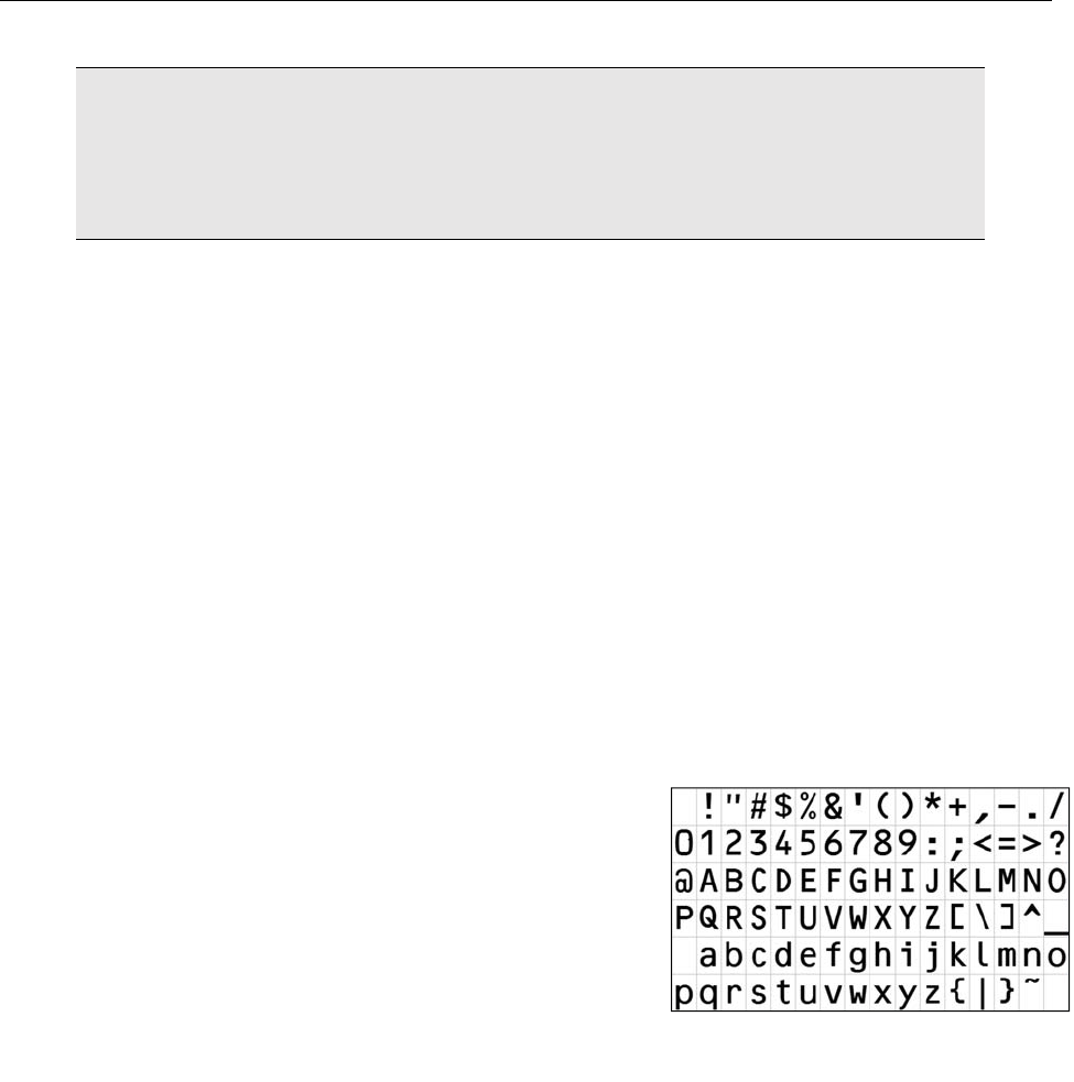
Lowercase letters, uppercase letters, and some special
characters are allowed in OCR-B MT font (6 to 14 points).
Shown to the right are the letters, numbers, and special
characters supported by OCR-B MT font (6 to 14 points)
Monospaced fonts, like OCR-B, are preferred and perform
better in the LVS-7510
Do not attempt to re-learn any of the supplied OCR-B MT
fonts
Number Validation
Verifies the expected order of any numerical series, detects duplicates and sequence errors, and matches
variable numbers with external data files.
Data and Code Matching
Verifies encoded data that represents human readable information and ensures synchronicity of multiple
fields within a label.
OCR-B font set
LVS-7510 Integrated System Operations Manual Version 20.2.X
LVS-7510 Integrated System Operations Manual Version 20.2.X Page 8 of 210
Functional Characteristics
The characteristics listed below apply to the LVS-7510 5.4” (137 mm) and 8.5” (216 mm) readheads.
Line Scan Camera: 400 DPI. Floating Sensor Head
Light Source: Red Light. 660 nm
Inputs / Outputs: USB 2.0 port. 5-Volt Power Supply
Maximum System Speed: 10 inches (254 mm) per second
ISO Verification
Verify: Any combination of linear, matrix or stacked codes to ISO print quality
standards including:
Linear (1D) Verifier Conformance (ISO/IEC 15416)
2-Dimensional (2D) Verifier Conformance (ISO/IEC 15415)
Orientation & Number: Ladder or Pickett fence orientation and any number of codes on a
label.
Read and Analyze: 1D and 2D to published International specifications, with an overall
ISO (ANSI) grade.
Minimum Linear (1D) Narrow
Bar Width:
Read only: 6.3 Mils (.0063”) (.160 mm)
Verification: 8.8 Mils (.0088”) (.223 mm)
Minimum 2D Cell Size: Read only: 10.0 Mils (.0100”) (.254 mm)
Verification: 12.5 Mils (.0125”) (.317 mm)
Reporting: Detailed data to be reported is in .csv file format for extraction by the
end user. Immediate reporting is available for viewing via the monitor.
Optical Character Verification (OCV)
Minimum Human Readable: .083 inches / 2.12 mm / 6 Printer Points
Data: Verifies variable and fixed data ascending, descending or from a file.
Read or Verify: Sequential string of alphanumeric characters (numbers 0 to 9 and
letters A to Z) against known field or database. Guidelines:
Characters must not touch or overlap
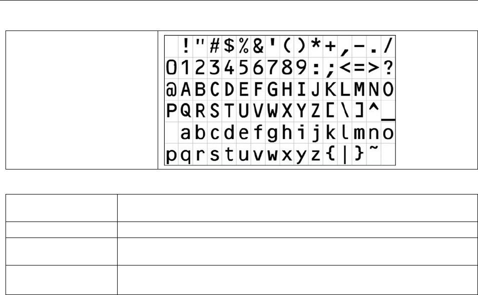
All uppercase letters in any font are allowed
Lowercase letters, uppercase letters, and some special
characters are allowed in OCR-B MT font (6 to 14 points).
Shown to the right are the letters, numbers, and special
characters supported by OCR-B MT font (6 to 14 points)
Monospaced fonts, like OCR-B, are preferred and perform better
in the LVS-7510
Do not attempt to re-learn any of the supplied OCR-B MT fonts
LVS-7510 Integrated System Operations Manual Version 20.2.X
LVS-7510 Integrated System Operations Manual Version 20.2.X Page 9 of 210
OCR-B font set
Blemish Detection
Print faults Detects skew, smear, print registration, die-cut errors, edge determination and
missing information.
Variable Data Allows user specified variable data within a pattern matching zone.
Red Light (660 nm) The LVS-7510 uses red light (660 nm) to detect blemishes; thus, color
blemishes in the red spectrum may not be properly detected.
Minimum point size Blemish Inspection: 5 Mils / .005” / .126 mm
Missing Period: 5 Mils / .005” / .126 mm
Number Validation
Validates numerical order requirements (ascending, descending, or alpha numeric series) to ensure
numbers are in the expected order
Use external data file for the validation of random number sequence
Detects duplicate numbers
Matching
Matches decoded data from a barcode to human readable text of that barcode
Matches multiple fields of data within the label area being inspected

LVS-7510 Integrated System Operations Manual Version 20.2.X
LVS-7510 Integrated System Operations Manual Version 20.2.X Page 10 of 210
Supported Symbologies
Below are a few of the symbologies supported by the LVS-7510. Contact Omron Microscan for a full list of
supported symbologies.
Aztec
Codabar
Code 128
Code 39
Code 93
Data Matrix
DataBar expanded
EAN-13
EAN-13 (2-digit supplemental) Stacked
EAN-13 (5-digit supplemental)
EAN-8
ECC-200 Data Matrix
GS1-128
GS1 Databar Limited
GS1 Databar
GS1 Databar-14
GS1 Data Matrix
Interleaved 2 of 5 (ITF)
Laetus Pharmacode
Micro QR Code
PDF417
QR Code
UPC-A
UPC-A (2-digit supplemental)
UPC-A (5-digit supplemental)
UPC-E
UPC-E (2-digit supplemental)
UPC-E (5-digit supplemental)
All applicable GS1 composite components
International Standards
ISO/IEC 15415
ISO/IEC 15416
All supported ISO/IEC symbology specifications
LVS-7510 Integrated System Operations Manual Version 20.2.X
LVS-7510 Integrated System Operations Manual Version 20.2.X Page 11 of 210
Modes of Operation
The LVS-7510 Integrated System software has two modes of operation: Design and Production modes.
The reason for the different modes is to support the segregation of duties and provide a productive and
secure environment for label production and validation.
Design and Production mode units are usually separate physical systems; however, it is possible to
configure one LVS-7510 system to operate in both modes and switch between Design and Production
modes when needed. The LVS-7510 is purchased as a Dual mode system. The software license codes are
to remain with the system hardware and are not transferable.
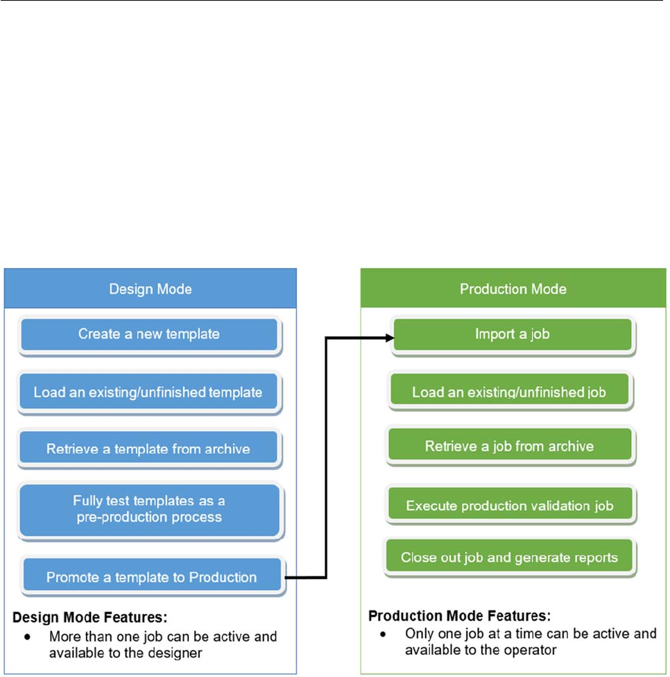
The primary differences between the two modes are that templates are created in Design mode only.
Templates are then promoted to production and become jobs. Production mode is used to execute the
promoted jobs. Highlights of each mode are listed below.
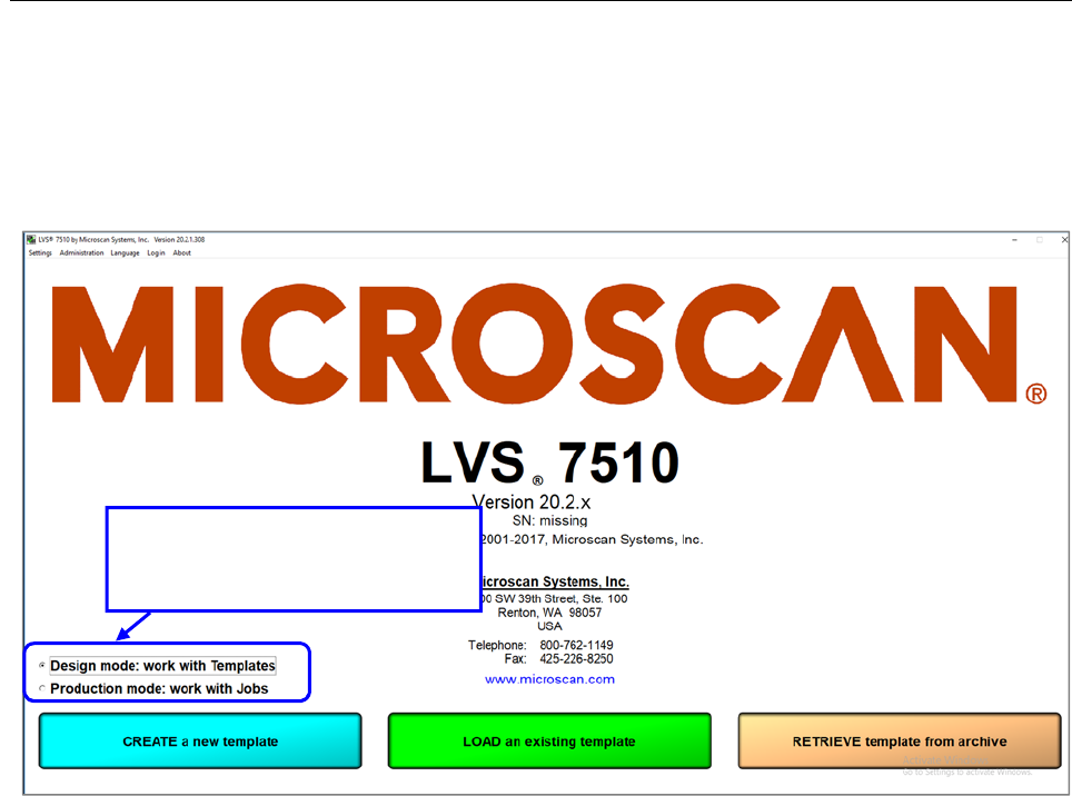
After user login, the Welcome screen displays the appropriate option buttons depending on the user’s
permissions and licensed modes of operation. The screen below shows a dual mode system that has
specific radio button controls to switch between Design and Production modes. The ability to switch between
modes is restricted to users who are assigned administrator permissions.
LVS-7510 Integrated System Operations Manual Version 20.2.X
LVS-7510 Integrated System Operations Manual Version 20.2.X Page 12 of 210
Design mode option buttons:
Create a new template
Load an existing template
Retrieve template from archive
Production mode option buttons:
Import a new job
Load an existing job
Retrieve job from archive
Dual mode system with radio
button controls to switch between
Design and Production modes.
LVS-7510 Integrated System Operations Manual Version 20.2.X
LVS-7510 Integrated System Operations Manual Version 20.2.X Page 13 of 210
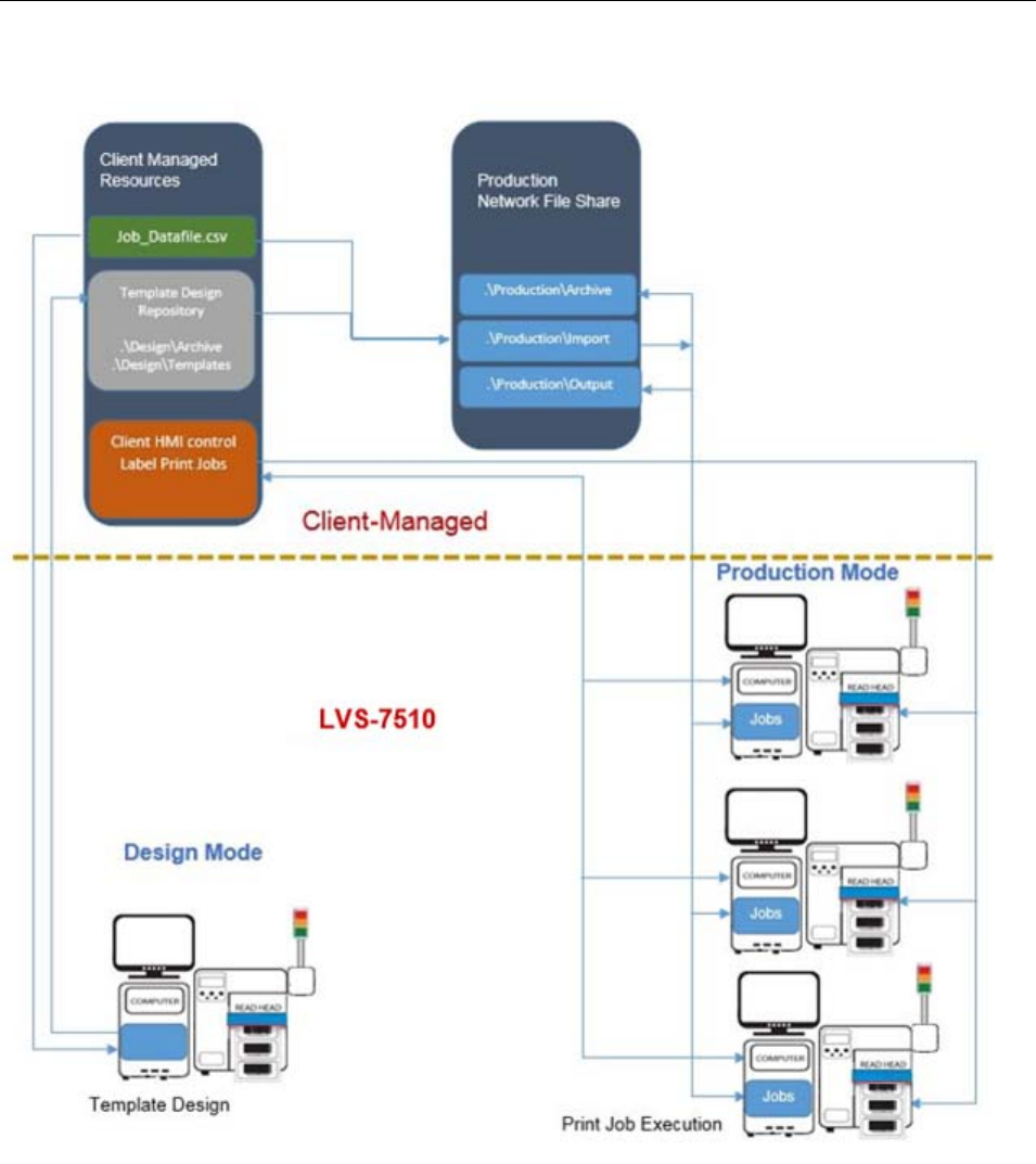
Example LVS-7510 Design and Production Mode Configuration

LVS-7510 Integrated System Operations Manual Version 20.2.X
LVS-7510 Integrated System Operations Manual Version 20.2.X Page 14 of 210
Design Mode
The Design mode system is a sophisticated software package with many inspection capabilities. It is best
operated by a well-trained individual or group to ensure the final production process runs as automated as
possible with as little operator interaction as possible. Design mode is intended to eliminate the set-up
process on the production line.
The Design mode system is a complete system that includes the LVS-7510 inspection unit, computer and
client printer. The system can be setup anywhere on the client’s network allowing multiple designers to share
template designs.
The process of capturing a Golden Image is through a physical printout of a mock production run of labels.
The mock production labels are printed and variable data attributes are tested in the Design mode.
If the optional PDF compare feature is enabled, the Design operator can compare the golden image against
an approved PDF using the supplied PDF comparison software. The comparison process is as simple as
loading an approved PDF from a folder location on the network and clicking “Play” from within the template
Design mode. The software runs a comparison against the captured golden image and highlights any
differences for the operator to review. Once satisfied that the PDF and Golden image match, the operator
clicks “Accept” and a report is stored with the job for any future reference. If any discrepancies are found, the
operator simply reprints a new image on the LVS-7510 and runs the comparison again.
In Design mode, more than one template can be active and available to the operator, who is trained in the
design and creation of the label inspection templates. A new template is created by clicking the “Create a
new template” button. A message box appears requesting the new template name to be created.
The template name is given to the folder where the LVS-7510 will create and save all files involved in the
execution of an actual production template. After design is complete, the designer will close out the template,
which zips up all files and stores them as one .zip file in the Archived folder of the Design mode LVS-7510.
Archived templates can be retrieved and activated allowing designers to update, copy and reuse previous
designs.
In Design mode, the LVS-7510 utilizes two job-related file folders for a specific purpose. The default naming
of the folders is based on their purpose, but can be changed to suit the client’s requirements. All folders can
be on a mapped network drive or local drive for each LVS-7510 system.
LVS-7510 Integrated System Operations Manual Version 20.2.X
LVS-7510 Integrated System Operations Manual Version 20.2.X Page 15 of 210
Define Template Path Locations in Design Mode
You must define where templates are located on a network drive or local folder. This section explains how to
configure the LVS-7510 path locations for the following:
Template folder:
In Design mode, this is where new templates are created and designed. Multiple templates under
development are allowed.
A new template is initiated by creating a new folder with the new job name in the Jobs folder.
Archived folder:
In Design mode, templates that are complete and closed out are zipped up and removed from the
Template folder to the Archived templates folder. The jobname.zip file is ready for execution in
Production mode or recall back into Design mode for changes and/or updates.
Define Location of Templates and Archive folders:
IMPORTANT: You must have administrator rights to perform the steps in this section.
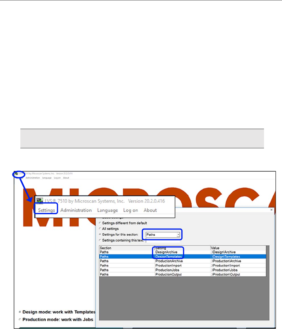
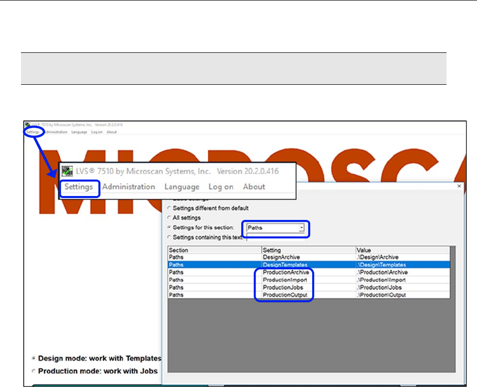
1. Log in to the LVS-7510 software.
2. Click “Settings” in the menu bar.
3. In “Settings for this section,” click the drop-down box and select “Paths.”
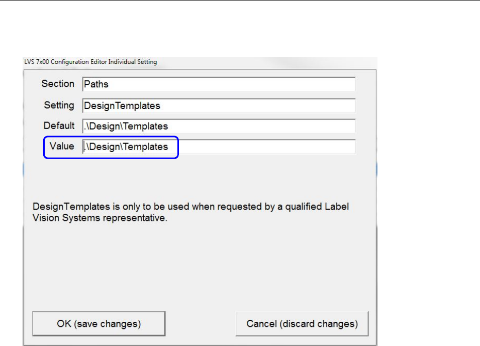
4. In the “Setting” column, double-click either “DesignTemplates” or “Design Archive.”
5. In the “Value” field, enter the path and then click “OK (save changes).” For example, by default the
value \Design\Templates will store templates on the local LVS-7510 computer.
For installations of software version 20.2.X on Windows® 7 Professional, Windows® 8.1 and
Windows 10 Professional operating systems: C:\LvsData\LVS 7500\Design\Templates.
Jobs created in earlier versions of the software are not supported. Manually backup any desired data
and manually delete the C:\Users\[User Login Name]\AppData\Roaming\Label Vision Systems\LVS
LVS-7510 Integrated System Operations Manual Version 20.2.X
LVS-7510 Integrated System Operations Manual Version 20.2.X Page 16 of 210
7500 or C:\Users\[User Login Name]\AppData\Roaming\Microscan\LVS 7510. Then, install software
release 20.2.X as a new installation.
6. Click “OK (save changes).”
7. Repeat steps 4 and 5 to set the DesignArchive path setting.

LVS-7510 Integrated System Operations Manual Version 20.2.X
LVS-7510 Integrated System Operations Manual Version 20.2.X Page 17 of 210
Production Mode
In Production mode, the LVS-7510 can be configured based upon the PC network implementation and level
of operator interaction desired.
Define Job Path Locations in Production Mode
In Production mode, the LVS-7510 utilizes the following folders:
Import folder
In Production mode, new jobs waiting to be executed are dropped into the Import folder. When a
designer executes a “Promote template to production,” the template is copied into the Production Import
folder. Multiple jobs can reside in the Import folder waiting to be acted on by the production operator.
This folder can be located on a network drive or local folder.
Jobs folder
In Production mode, the operator will select a job from the Import folder to be executed. The job is
unzipped and a folder is created in the Jobs folder with the job name. Only one job can reside in the
Jobs folder. To clear the active job from the Jobs folder the production operator must execute “Close
out job” which zips up the job along with run related data. The executed jobname.zip file is copied into
the Production Archive folder. The job is deleted from the Jobs folder to make ready for the import of a
new job. For Job Auto-Execute functionality, see page 90.This folder can be located on a network drive
or local folder.
Output folder
In Production mode, when a job is completed and closed out, the output reporting and summary file(s)
are written to this folder path. This folder can be located on a network drive or local folder.
Archive folder
This folder contains the detailed production data for a job that includes the inspection results for each
label. Jobs that are complete and closed out are zipped up and moved from the Jobs folder to the
Archive folder. This folder can be located on a network drive or local folder.
LVS-7510 Integrated System Operations Manual Version 20.2.X
LVS-7510 Integrated System Operations Manual Version 20.2.X Page 18 of 210
Define Location of Production folders
IMPORTANT: You must have administrator rights to perform the steps in this section.
1. Log into the LVS-7500 software.
2. Click “Settings” in the menu bar.
3. In “Settings for this section,” click the drop-down box and select “Paths.”
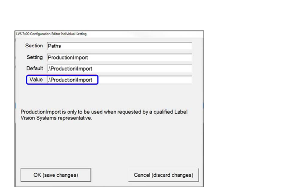
4. In the “Setting” column, double-click one of the production path settings (such as ProductionImport).
5. In the “Value” field, enter the path and then click “OK (save changes).” For example, by default the
value \Production\Import will store templates on the local LVS-7510 computer.
For installations of software version 20.2.X on Windows® 7 Professional, Windows® 8.1 and
Windows 10 Professional operating systems: C:\LvsData\LVS 7500\Production\Import
Jobs created in earlier versions of the software are not supported. Manually backup any desired
data and manually delete the C:\Users\[User Login Name]\AppData\Roaming\Label Vision
Systems\LVS 7500 or C:\Users\[User Login Name]\AppData\Roaming\Microscan\LVS 7510. Then,
install software release 20.2.X as a new installation.
LVS-7510 Integrated System Operations Manual Version 20.2.X
LVS-7510 Integrated System Operations Manual Version 20.2.X Page 19 of 210
6. Click “OK (save changes).”
7. Repeat steps 4 through 6 to set the ProductionJobs, ProductionOutput and ProductionArchive path
setting.
LVS-7510 Integrated System Operations Manual Version 20.2.X
LVS-7510 Integrated System Operations Manual Version 20.2.X Page 20 of 210
Log In
Follow the steps below to log in to the LVS-7510.
Note: Users with the “Automatic Login” feature enabled bypass the Welcome screen and
automatically access the Welcome screen where they are able to work according to the
system setup and their individual permissions (as shown in step 3 below showing the Design
Mode Welcome Screen). Refer to “Appendix E: Automatic Login” for more information on
using the “Automatic Login” feature.
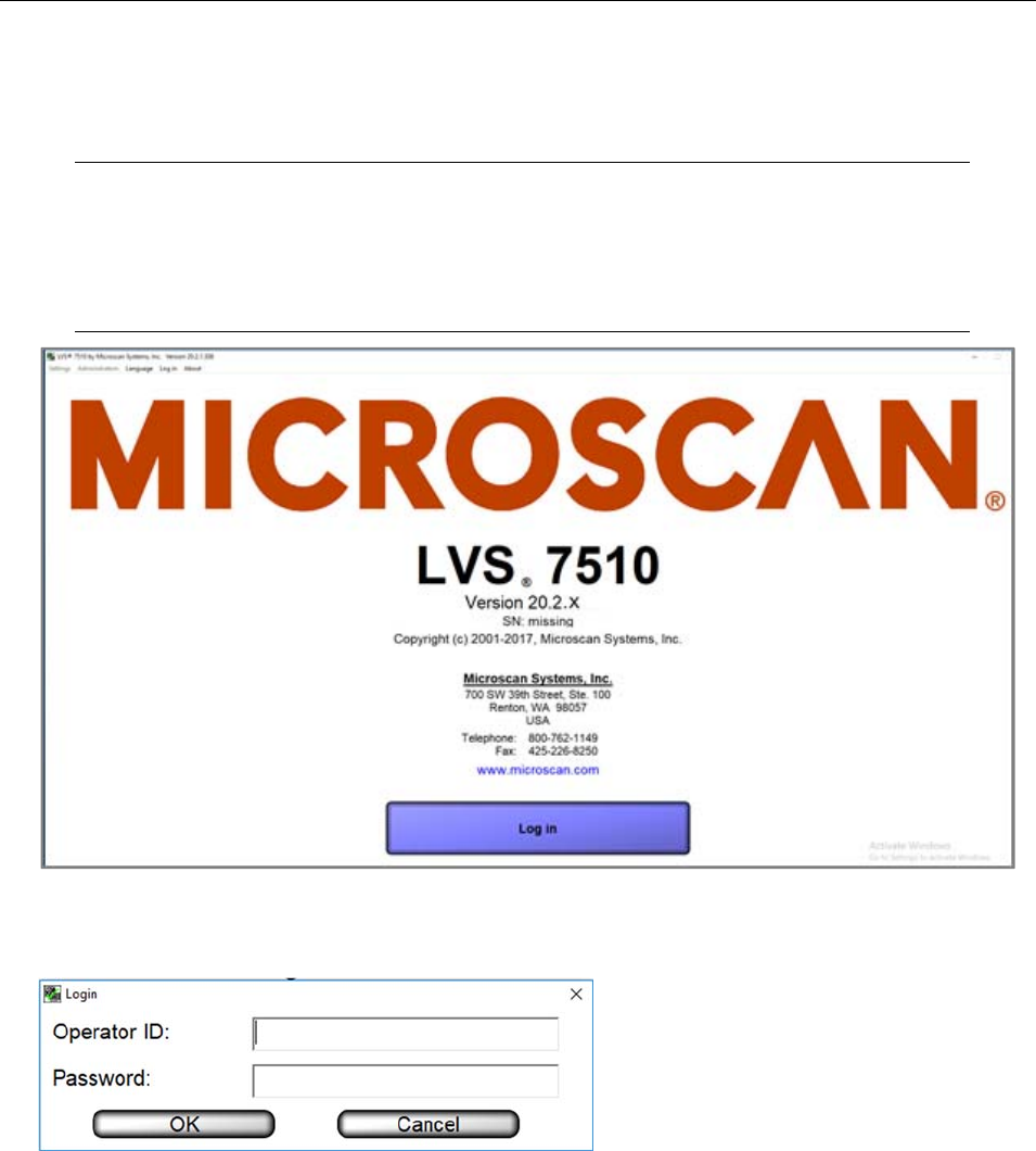
1. Start the LVS-7510 software. The Welcome screen appears (see below).
2. Click the Log In button. The Login box appears. Enter the Operator ID and Password, and then click
OK.
When using the LVS-7510 for the first time, enter Admin in both fields (Operator ID field and
Password field).
Refer to the Operators section for detail instructions on creating operator IDs and password
(Welcome Screen Overview Administration Operators)
LVS-7510 Integrated System Operations Manual Version 20.2.X
LVS-7510 Integrated System Operations Manual Version 20.2.X Page 21 of 210
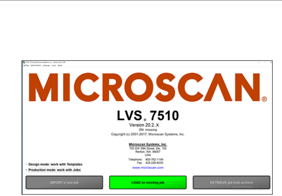
3. After login, the operating mode option buttons are displayed. As explained previously in the “Modes of
Operation” section, there are two operating modes: Design and Production. Refer to the following
sections for more information:
Design Mode: Create a New Template
Production Mode: Import a new Job
LVS-7510 Integrated System Operations Manual Version 20.2.X
LVS-7510 Integrated System Operations Manual Version 20.2.X Page 22 of 210
Welcome Screen Overview
When starting the LVS-7510 software, the Welcome screen appears (see below). This screen allows you to
log in to the LVS-7510 (see “Log In” section below) and access the following menu bar functions:
Settings
Administration
Language
Log In
About
Refer to the following sections for more information about each menu bar function.
LVS-7510 Integrated System Operations Manual Version 20.2.X
LVS-7510 Integrated System Operations Manual Version 20.2.X Page 23 of 210
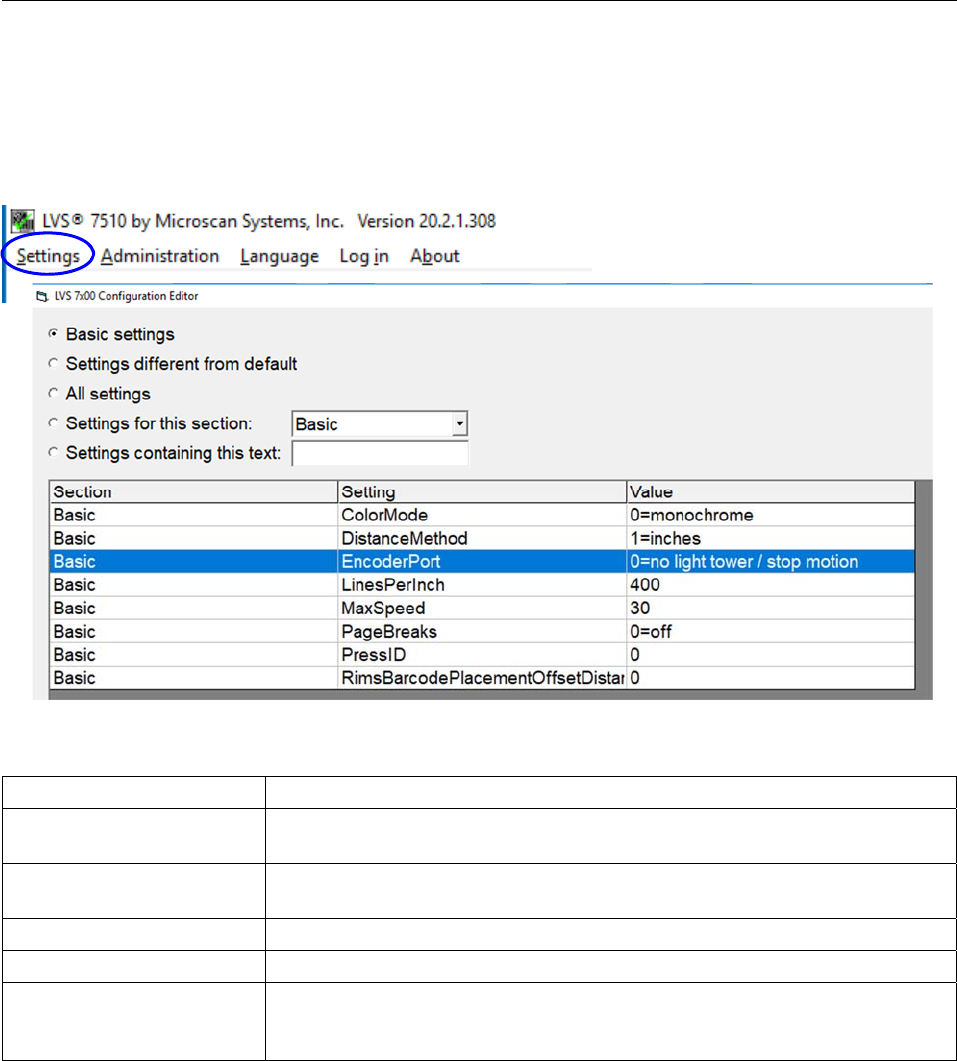
Settings
The Settings menu bar feature opens the LVS-7510 Configuration Editor which allows you to configure the
basic and advanced features and functionality of the LVS-7510. A user must be assigned administrator rights
to access the “Settings” menu bar.
The LVS-7510 Configuration Editor offers the following options:
Option Description
Basic settings Select this option to display the settings considered to be basic to LVS-
7510 configuration.
Settings different from
default Select this option to display any values that have been modified to a value
other than the default value.
All settings Select this option to display all settings listed alphabetically by “Section.”
Settings for this section Click the drop-down box to display all settings for the selected section.
Settings containing this
text Enter a text string to search for settings containing the entered text. For
example, typing “camera” in the text field will display all settings containing
the word “camera.”
LVS-7510 Integrated System Operations Manual Version 20.2.X
LVS-7510 Integrated System Operations Manual Version 20.2.X Page 24 of 210
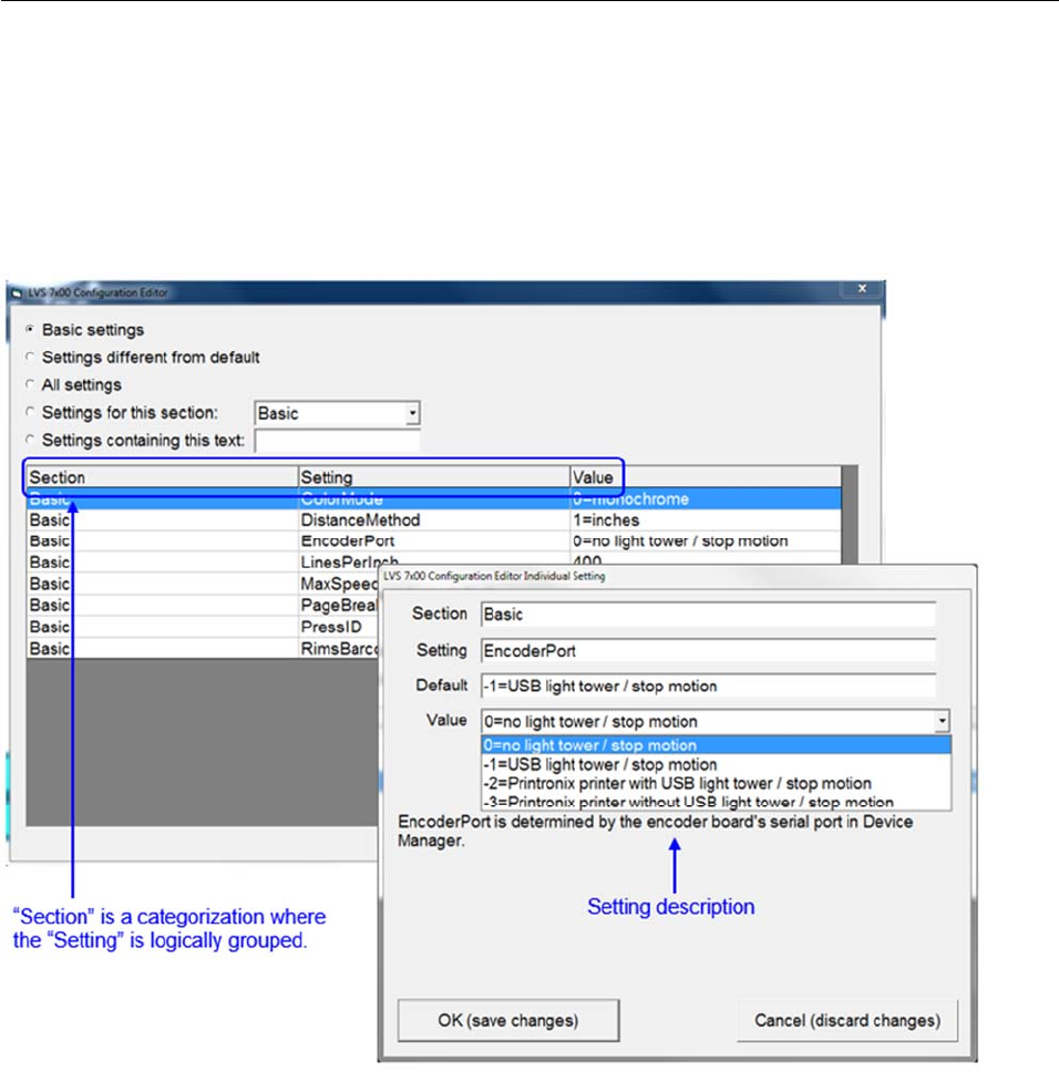
Each setting is grouped by “Section,” “Setting,” and “Value.”
Double-click a setting row. The “LVS-7510 Configuration Editor Individual Setting” window appears which
provides the Section, Setting, Default, Value, and Setting Description.
The only editable field is the “Value” field. All other fields cannot be edited.
Click “OK (save changes)” to save your changes or “Cancel (discard changes)” to discard any changes
made on the screen.
LVS-7510 Integrated System Operations Manual Version 20.2.X
LVS-7510 Integrated System Operations Manual Version 20.2.X Page 25 of 210
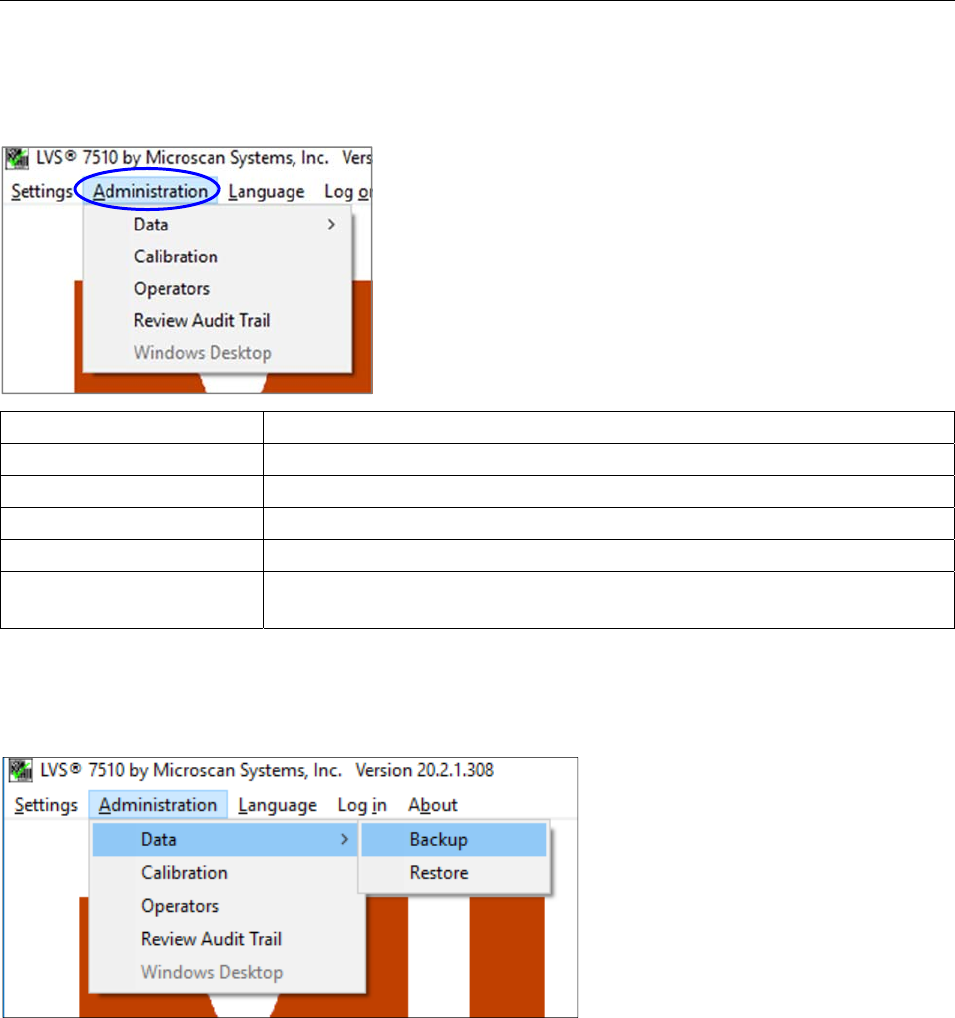
Administration
The Administration menu bar feature allows you to choose from the following options:
Option Description
Data Backup or restore jobs.
Calibration Calibrate the LVS-7510.
Operators Select operator permissions.
Review Audit Trail Review an audit trail of all activity performed on the LVS-7510.
Windows® Desktop Access the Windows® desktop (operator must have access rights to
perform this feature).
Refer to the following sections for more information about each feature.
Data
The Data feature allows you to backup or restore templates and jobs.
The location of data is dependent on the current mode of operation.
If in Design mode, templates are located in the following directories:
For installations of software version 20.2.X on Windows® 7 Professional and Windows® 8.1
Professional operating systems: C:\LvsData\LVS 7500\Design\Templates
Jobs created in earlier versions of the software are not supported. Manually backup any desired data
and manually delete the C:\Users\[User Login Name]\AppData\Roaming\Label Vision Systems\LVS 7500
or C:\Users\[User Login Name]\AppData\Roaming\Microscan\LVS 7510. Then, install software release
20.2.X as a new installation.
If in Production mode, the job data is located in the following directories:
For installations of software version 20.2.X on Windows® 7 Professional and Windows® 8.1
Professional operating systems: C:\LvsData\LVS 7500\Production
LVS-7510 Integrated System Operations Manual Version 20.2.X
LVS-7510 Integrated System Operations Manual Version 20.2.X Page 26 of 210
Jobs created in earlier versions of the software are not supported. Manually backup any desired data
and manually delete the C:\Users\[User Login Name]\AppData\Roaming\Label Vision Systems\LVS 7500
or C:\Users\[User Login Name]\AppData\Roaming\Microscan\LVS 7510. Then, install software release
20.2.X as a new installation.
Data Backup
To backup data from the source directory to a different folder, drive or network location, follow the steps
below.
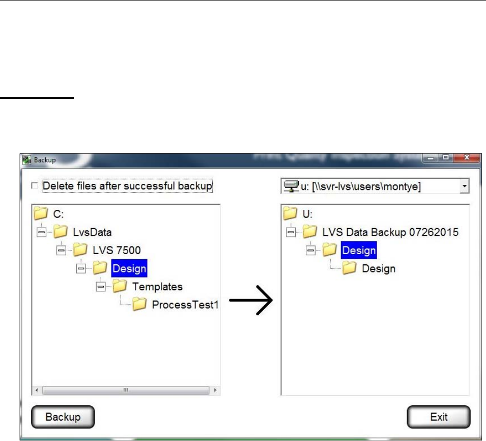
1. Select Administration Data Backup. The following screen appears.
2. On the left side, select the data folders that you want to backup. Multiple folders can be selected at one
time by pressing and holding the CTRL keyboard button, and then clicking each folder.
3. On the right side, select the folder where the files should be saved. The same drive letter cannot be used
for source and destination drive selection.
4. If you want to delete the files after backup, click the Delete files after successful backup checkbox.
5. Click Backup.
LVS-7510 Integrated System Operations Manual Version 20.2.X
LVS-7510 Integrated System Operations Manual Version 20.2.X Page 27 of 210
Data Restore
To restore data from a folder, drive or network location to the Design or Production folders, follow the steps
below.
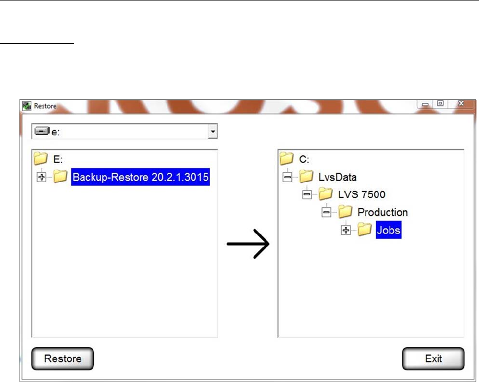
1. Select Administration Data Restore from the menu bar. The following screen appears.
2. On the left side, select the folder(s) you want to restore. Multiple folders can be selected at one time by
pressing and holding the CTRL keyboard button and then clicking each folder.
3. On the right side, select the “Jobs” directory.
4. Click Restore.
LVS-7510 Integrated System Operations Manual Version 20.2.X
LVS-7510 Integrated System Operations Manual Version 20.2.X Page 28 of 210
Calibration
The Calibration feature allows you to calibrate the LVS-7510. Calibration is required to keep the LVS-7510
in a standard imaging configuration. It is recommended that the system be recalibrated each time the printer
ribbon is changed.
To calibrate the LVS-7510, you need an Omron Microscan Calibration Card in perfect condition with all of the
calibration information filled out on the card. Only Omron Microscan calibration card part #98-CAL017 should
be used to calibrate LVS-7510.
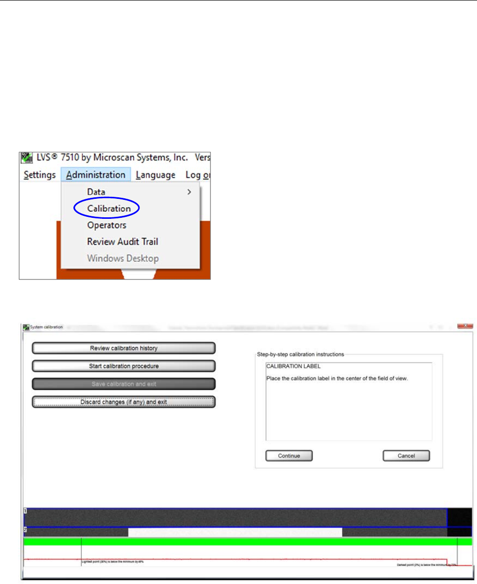
1. Select Administration, and then Calibration from the menu bar.
2. Click the Start calibration procedure button. The following screen appears.
LVS-7510 Integrated System Operations Manual Version 20.2.X
LVS-7510 Integrated System Operations Manual Version 20.2.X Page 29 of 210
3. Place the white portion of the calibration card in the field of view. The entire image should appear white.
Click Continue. The following page appears. Make sure that the sensor head is closed in the ALL
BLACK calibration step.
Tip: Step-by-step calibration instructions are also listed on the right side of the screen.
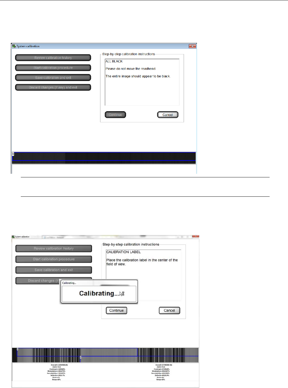
4. Place the Omron Microscan calibration card under the camera so that as many barcodes are within the
field of view as possible. If the calibration card does not fit under the sensor, flip up the sensor head and
place the card on the sensor such that it sees the barcodes. The system displays the ISO/IEC 15416
parameters of all the decoded barcodes that the camera detects. Next, click Continue to calibrate.
LVS-7510 Integrated System Operations Manual Version 20.2.X
LVS-7510 Integrated System Operations Manual Version 20.2.X Page 30 of 210
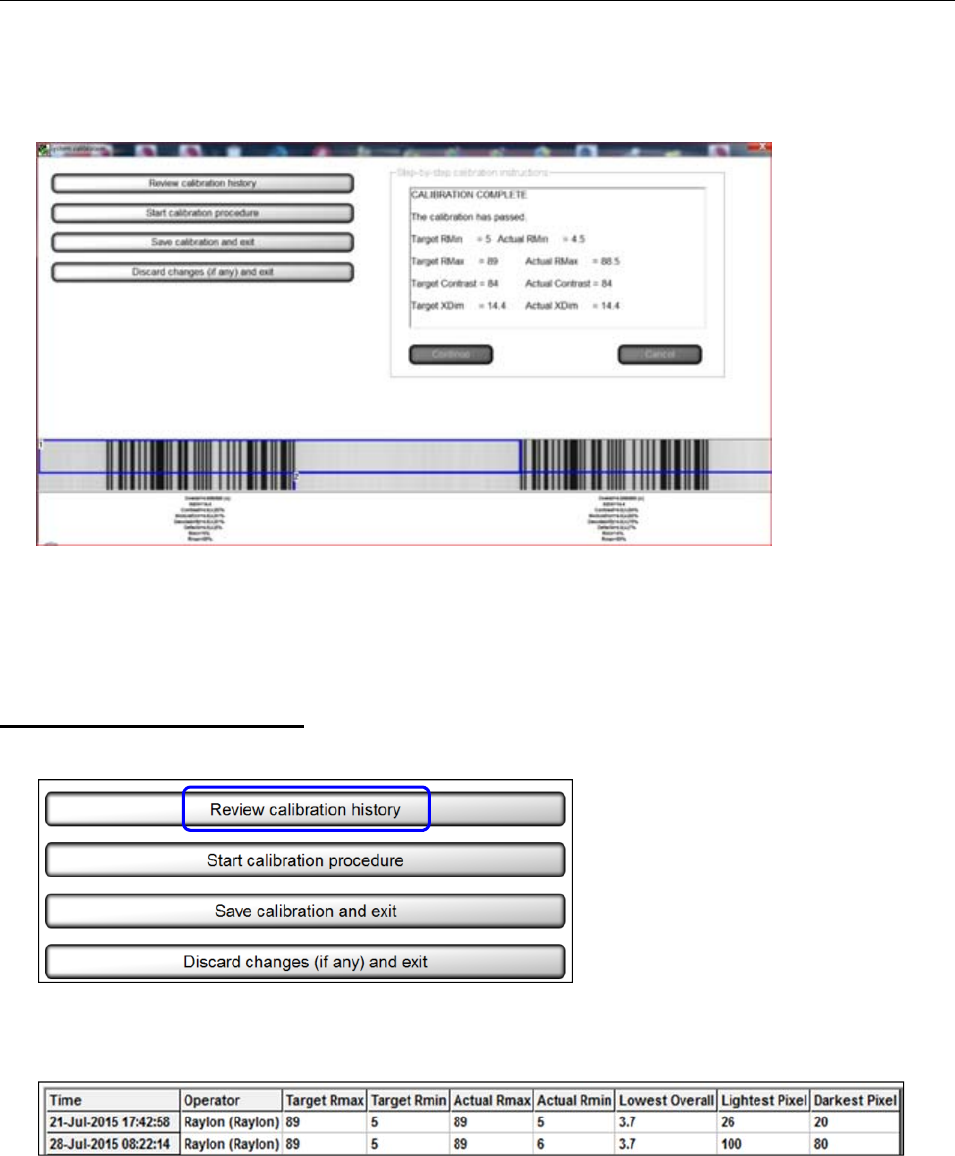
5. Calibration is complete. If calibration fails, repeat the calibration process. Be sure to inspect the
calibration card carefully for damages and impurities. If the problem still persists, contact Omron
Microscan for technical assistance.
6. Click the Save calibration and exit button to save the calibration results and return to the Welcome
screen. After saving the calibration results, the system automatically saves the Operator ID in the
calibration history log (see the next section entitled “Review Calibration History” for more information).
7. Click the Discard changes (if any) and exit to discard the calibration results and return to the Welcome
screen.
Review Calibration History
1. Click Review calibration history.
2. The CSV file viewer page appears (see below), which is time stamped, provides the operator ID, and
displays the “before” and “after” calibration image readings. The fields are not user editable in the viewer;
they are printable if desired.
LVS-7510 Integrated System Operations Manual Version 20.2.X
LVS-7510 Integrated System Operations Manual Version 20.2.X Page 31 of 210
Operators
Two options are available for managing operator permissions in the LVS-7510.
Manage operator permissions using Microsoft® Active Directory. The LVS-7510 software
integrates with Microsoft Active Directory. LVS-7510 users are granted user privileges based on
Microsoft authentication and LVS-7510 permissions are assigned based on group membership in
Omron Microscan-specific Active Directory groups.
To manage operator permissions using Microsoft® Active Directory, refer to “Appendix F: Managing
Operator Permissions in Microsoft® Active Directory.”
Manage operator permissions within the LVS-7510 software. Users with LVS-7510 administrator
access can create and manage permissions of other operators completely within each LVS-7510
system. User passwords are encrypted and stored in the local Operator.dat file. Each user has a
password expiration date and failed password count, which are also stored in the same local file. To
manage operator permissions within the LVS-7510 software, refer to the steps below.
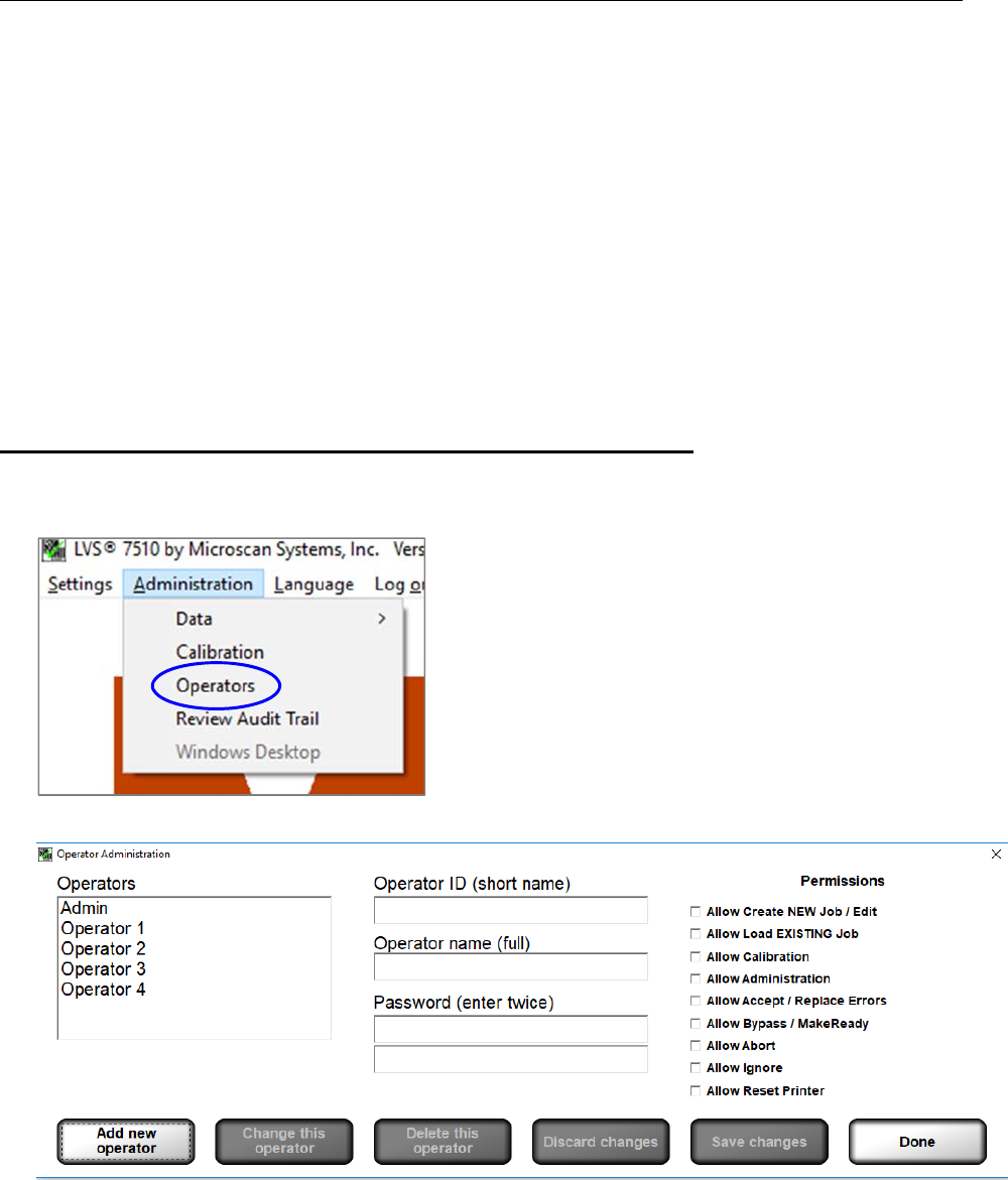
Manage Operator Permissions within the LVS-7510 Software
The Operators feature allows you to establish operator permissions.
1. Select Administration, and then Operators from the menu bar.
2. The following screen allows you to setup operators and operator permissions.
LVS-7510 Integrated System Operations Manual Version 20.2.X
LVS-7510 Integrated System Operations Manual Version 20.2.X Page 32 of 210
The buttons at the bottom of the screen are described below:
Option Description
Add new operator Click the Add new operator button to add a new operator, and then complete
the following fields:
Operator ID (short name)
Operator name (full name)
Password. Each password must consist of the following:
o At least 8 characters
o At least 1 letter from A to Z
o At least 1 number from 0 to 9
Select the desired permissions
Click Save changes to save your changes or Discard changes to
discard and not save your changes
Change this operator Allows you to make changes to an operator’s permissions.
Select the operator’s name from the Operators list
Click the Change this operator button
Make any necessary changes
Click the Save Changes button to save your changes or the Discard
Changes button to not save your changes
Delete this operator Select the operator’s name from the Operators list, and then click the Delete
this operator button.
Discard changes Click this button to discard any changes made to any operator details.
Save changes Click this button to save changes made to any operator details.
Done Click this button after all changes are complete.
Permissions
Operator permissions are described in the table below.
Permission Description
Allow Create NEW Job /
Edit Allows the operator to create, edit and delete a job.
Allow Load EXISTING
Job Allows the operator to load and execute existing jobs. Existing jobs cannot be
edited.
Allow Calibration Allows the operator to perform calibration.
Allow Administration Allows the operator access to the “Administration” menu bar feature where
operators and operator permissions are set up. See “Welcome Screen
Overview” “Administration” “Operators” for more information.
Allow Accept / Replace
Errors Allows the operator to accept or replace errors.
Allow Bypass /
MakeReady Allows the operator to use the “Bypass” and “MakeReady” buttons on the
"Design and Production Mode: Running" screen.
Allow Abort Allows the operator to stop running the job after three consecutive errors of the
same type are detected (except Foreground and Background errors). For
more information, refer to Appendix H: LVS-7510 Printronix Integrated
System” Printing Stopped Error Message.
LVS-7510 Integrated System Operations Manual Version 20.2.X
LVS-7510 Integrated System Operations Manual Version 20.2.X Page 33 of 210
Permission Description
The “Allow Abort” permission is applicable only when the LVS-7510 is in
Design or Production mode (see the “Modes of Operation” section for more
information on Design and Production modes).
Allow Ignore Allows the operator to ignore a failed label and continue printing the next label
in the job after three consecutive errors of the same type are detected (except
Foreground and Background errors). For more information, refer to Appendix
H: LVS-7510 Printronix Integrated System” Printing Stopped Error
Message.
The “Allow Ignore” permission is applicable only when the LVS-7510 is in
Design or Production mode (see the “Modes of Operation” section for more
information on Design and Production modes).
Allow Reset Printer Allows the operator to reset the printer. For more information, refer to
Appendix H: LVS-7510 Printronix Integrated System” Reset the Printer.
The “Allow Reset Printer” permission is applicable only when the LVS-7510 is
in Design or Production mode (see the “Modes of Operation” section for more
information on Design and Production modes).
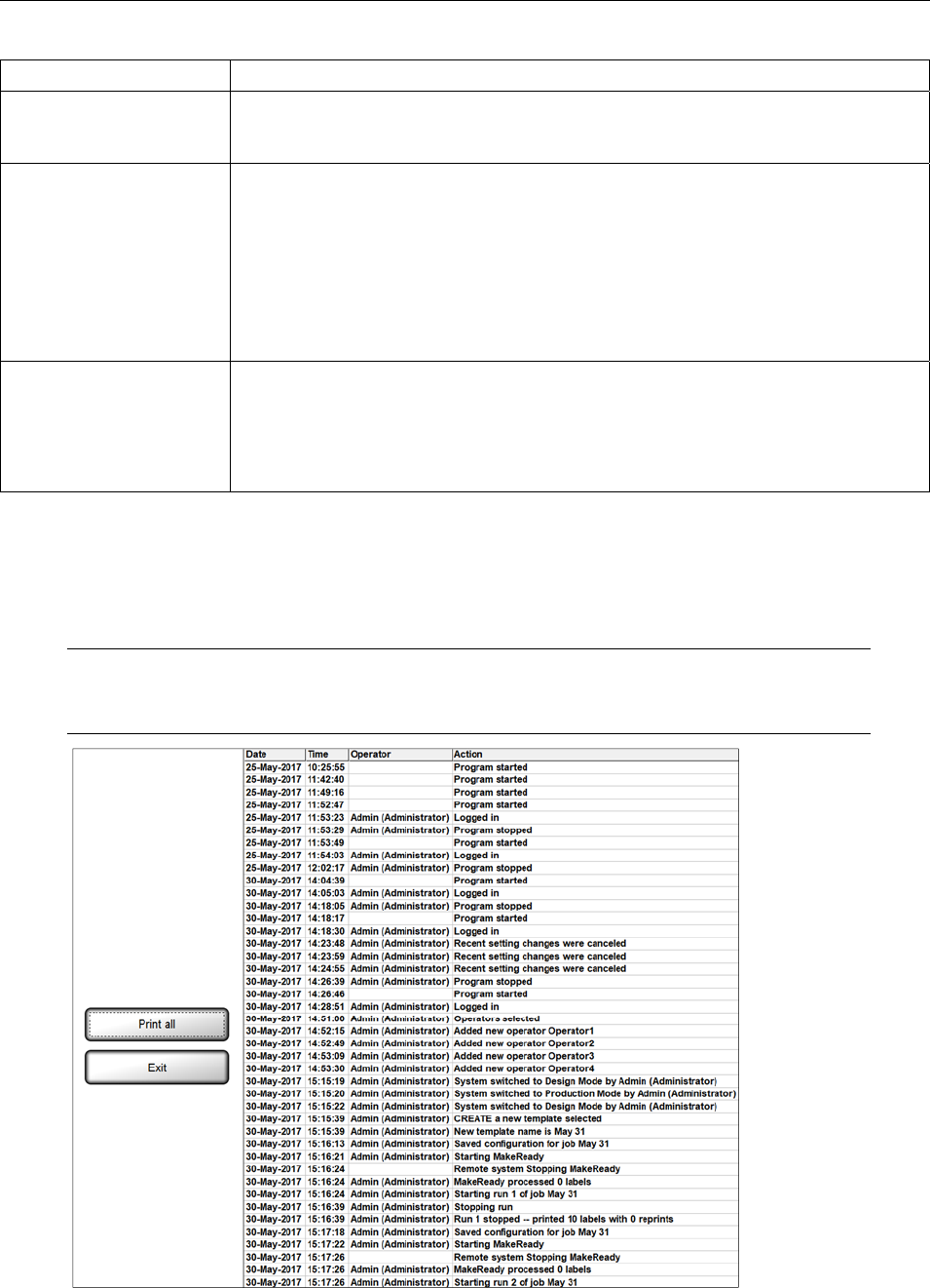
Review Audit Trail
The Review Audit Trail feature allows you to monitor user activity.
Click Print all to print the audit trail report.
Click Exit to exit the audit trail report and return to the Welcome screen.
Note: The audit trail is saved as a .txt file in the Production/Output folder and can be
exported into external applications such as MS Excel.
LVS-7510 Integrated System Operations Manual Version 20.2.X
LVS-7510 Integrated System Operations Manual Version 20.2.X Page 34 of 210
Windows Desktop
When enabled, Windows® desktop allows a user who has been granted permission rights to access the
Windows® desktop from the LVS-7510 system.
Accessing the Windows® desktop from the LVS-7510 is normally disabled to comply with CFR-21 part 11
requirements.
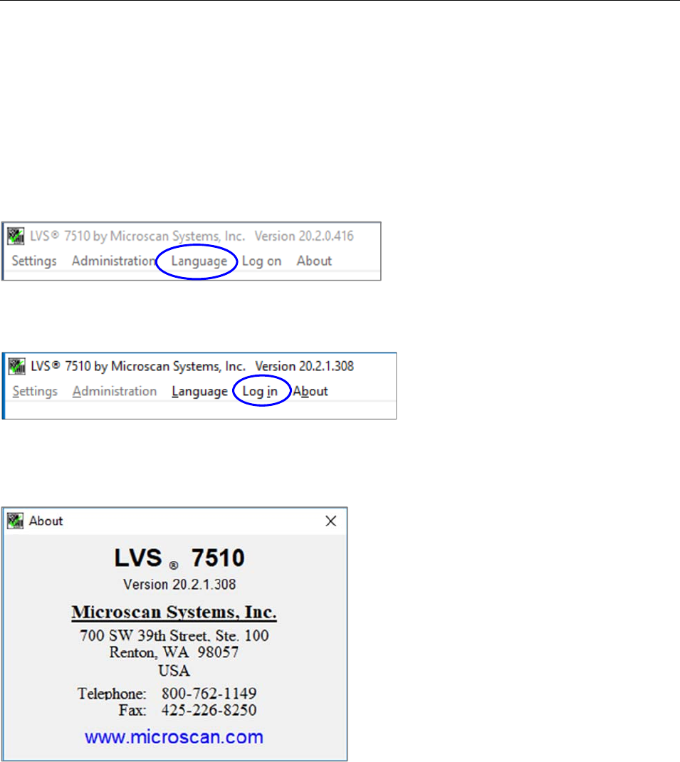
Language
The Language menu bar feature allows you to change the language for available translated text.
Log In
The Log In menu bar feature allows you to log in or log out of the LVS-7510.
About
The About menu bar feature allows you to view the LVS-7510 software version and Omron Microscan
contact information.
LVS-7510 Integrated System Operations Manual Version 20.2.X
LVS-7510 Integrated System Operations Manual Version 20.2.X Page 35 of 210
Design Mode: Create a New Template
To create a new template in Design mode, follow the steps below.
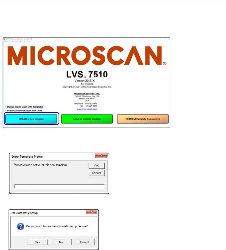
1. Click the “Create a new template” button. The “Enter Template Name” message box appears requesting
a new template name.
2. Enter a name for the template being created and click “OK.”
3. At the “Use Automatic Setup” message box, choose “Yes” to use the Automatic Setup feature or “No” to
use the Manual Setup feature. A description of each setup feature is described below.
Automatic Setup – Utilizing a box drawn around one label, the LVS-7510 finds all labels across the
roll (if multiple labels across the width of the web are present) and automatically draws blemish and
barcode sectors with the default setting stored for the corresponding sector types. After this
automated process is complete, the system will be at the “Step 7: Save Job to Disk” screen where
the user is able to change the template name and description if desired.
Manual Setup – Guides the user through each step in creating a new template. The user must
manually create sectors around blemishes and barcode sectors.
For instructions on creating a new template using the Automatic Setup feature, see the next section:
“Create a Template Using Automatic Setup.” For instructions on creating a new template using the
Manual Setup feature, see the section: “Create a Template Using Manual Setup.”
LVS-7510 Integrated System Operations Manual Version 20.2.X
LVS-7510 Integrated System Operations Manual Version 20.2.X Page 36 of 210
Create a Template Using Automatic Setup
1. Follow steps 1, 2, and 3 above (making sure to select “Yes” at the “Use Automatic Setup” message
box.)
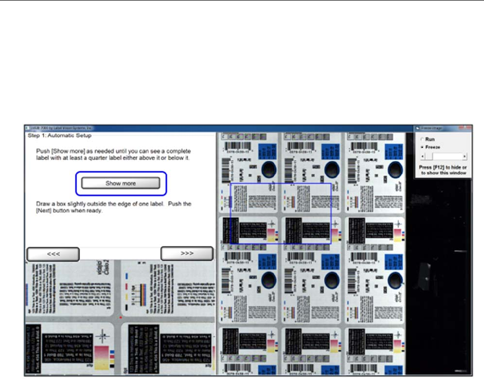
2. Print several labels. Stop when the screen from top to bottom is filled with labels. Click the “Show more”
button until you can see a complete label with at least a quarter label either above or below the label. If
necessary, print several more labels until the screen is again filled with labels from top to bottom.
LVS-7510 Integrated System Operations Manual Version 20.2.X
LVS-7510 Integrated System Operations Manual Version 20.2.X Page 37 of 210
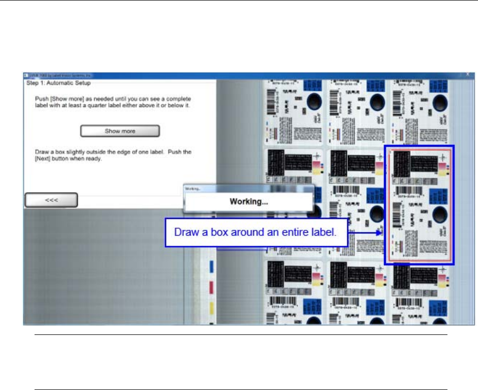
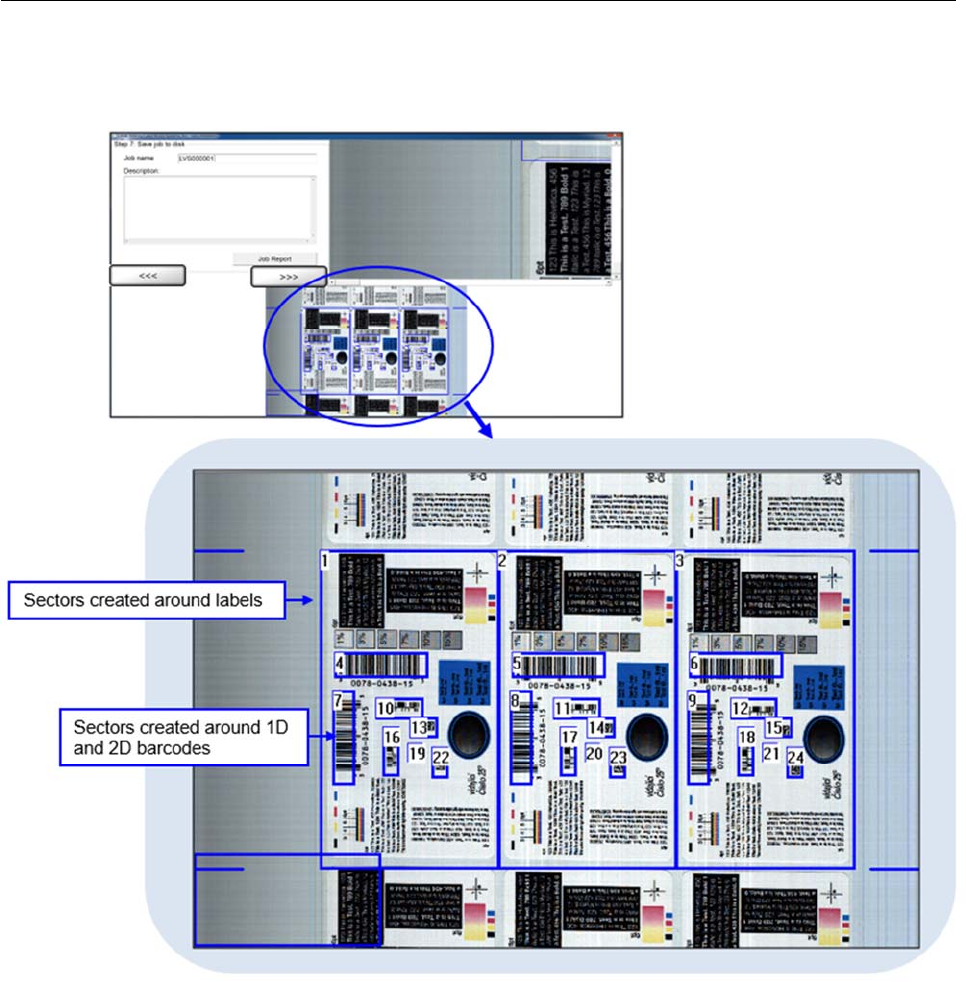
3. Draw a sector around an entire label (starting in the lower right corner moving to the top left corner) and
then click the right arrow button. A “Working” message appears indicating the system is analyzing the
label. The “Step 7: Save Job to Disk” screen appears.
Note: Automatic Setup moves from the Step 1 screen directly to the Step 7 screen of the
template creation process. Steps 2 through 6 are accessible if needed. For details about
steps 2 through 6, refer to the section: “Create a Template Using Manual Setup.”
LVS-7510 Integrated System Operations Manual Version 20.2.X
LVS-7510 Integrated System Operations Manual Version 20.2.X Page 38 of 210
4. The LVS-7510 automatically detects and creates blemish sectors around any other labels across the
roll, and also detects and creates sectors around any 1D or 2D barcodes in each label.
5. Enter the name of the template in the Job name field.
6. Optional: Enter a template description in the Description field.
7. Click Job Report to view, print or save the Job Report, which shows the settings for all created sectors.
See the section entitled “LVS-7510 Job Report” for more information.
8. Click the right arrow button; this saves the current template configuration.
LVS-7510 Integrated System Operations Manual Version 20.2.X
LVS-7510 Integrated System Operations Manual Version 20.2.X Page 39 of 210
Create a Template Using Manual Setup
As directed in steps 1, 2, and 3 in the “Design Mode: Create a New Template” section:
1. Click the “Create a new template” button on the “Welcome” screen.
2. In the “Enter Template Name” message box, enter a name for the template being created and then click
“OK.”
3. At the “Use Automatic Setup” message box, select “No.” The “Step 1: Set label repeat” screen appears.
Refer to the section below for further instructions.
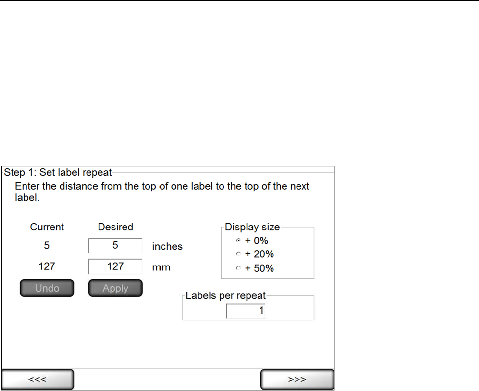
Step 1: Set Label Repeat
1. In the Desired column, enter the desired value into the inches or millimeter (mm) fields.
2. Click the Apply button, or click the Undo button to clear the values entered into the Desired column.
3. You may choose to change the Display Size. Options include:
0% (Normal) – This setting must be used for Integrated Printronix and Zebra models.
20% (Normal + 20%)
50% (Normal + 50%) (Default size)
4. In the Labels per repeat field, enter the amount of labels across the width of the web. This field is critical
for allowing Global Copy capability in Manual setup. See the Global Copy section for more information.
5. Click the right arrow button.
LVS-7510 Integrated System Operations Manual Version 20.2.X
LVS-7510 Integrated System Operations Manual Version 20.2.X Page 40 of 210
Step 2: Synchronize
Synchronization Overview
The LVS-7510’s synchronization takes the image and electronically creates a repeating pattern for locking.
This process emulates the effect generated by a traditional Photo Optic trigger. The principal is simple
enough to understand with some pictorial illustrations. The LVS-7510 takes the image and averages all
pixels going across in rows, then performs the same averaging for all pixels going down in columns (see
example below).
If we were to average all the pixels going across in rows, it would look like a strip added to the right of the
picture below.
LVS-7510 Integrated System Operations Manual Version 20.2.X
LVS-7510 Integrated System Operations Manual Version 20.2.X Page 41 of 210
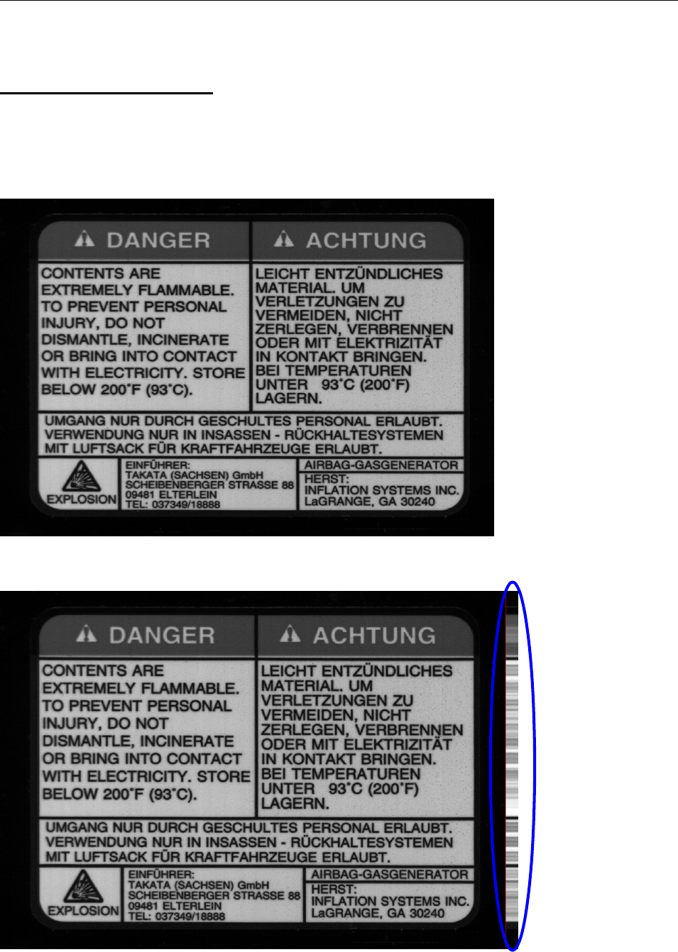
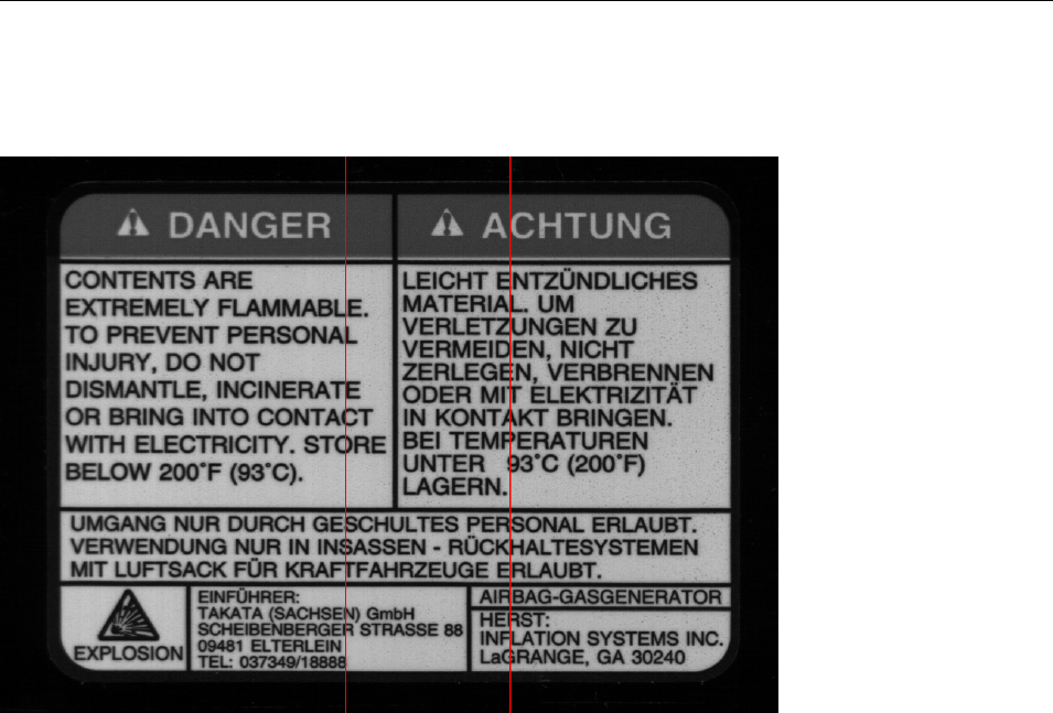
As you can see there are portions of this image attached to the right of the thin, red, vertical line that look
similar. These portions are where the text goes across the label. The part we are most interested in seeing
are the portions that had the black lines going across the image. The image above shows three definite
sharp black lines that are unequally spaced apart. This is good as they cannot be mistaken for one another.
The black line closest to the top also has a large darker portion above it since the label had a darker border
around the words “Danger” and “Achtung”. Solid lines are good to utilize, especially when unevenly spaced.
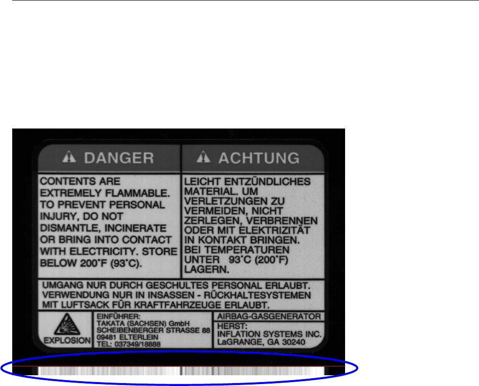
Now following the same principal going down in columns from top to bottom we get a picture that looks like
this (see below).
This example has much less definition through the whole image when looking at the average across the
bottom of the label (below the red line). The large vertical black line that was through the center has made
itself the most obviously defined dark line on the lighter background. Also, the spaces between the print
through the center of the label have made the average to the left of the center black line very light in
contrast.
LVS-7510 Integrated System Operations Manual Version 20.2.X
LVS-7510 Integrated System Operations Manual Version 20.2.X Page 42 of 210
Since the smaller the synchronization portion of an image is, the faster it is to process, we can make a guess
at the best area to use as a synchronization slice, which is the smallest portion of the image possible to hold
good image registration. Below is the image of where we would want to designate as our “sync slice”.
When we average just the portions between the lines, we can process and lock in the repeat much faster
than doing the entire image. Keeping it as small as possible is the best rule of thumb, though sometimes it
may need to be large to accomplish the goal.
As another rule of thumb, if your label has variable data on it, that area should be avoided if possible. If it
cannot be avoided you will need to do the inverse, and make the slice as wide as possible to distribute the
variation into the average.
LVS-7510 Integrated System Operations Manual Version 20.2.X
LVS-7510 Integrated System Operations Manual Version 20.2.X Page 43 of 210
Synchronization Steps
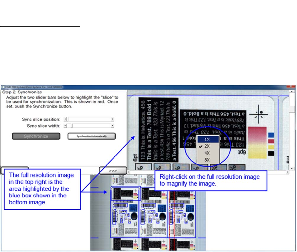
Screen Overview:
The top right image is the full resolution image. The slide bar to the right and below the image allows the
operator to view different areas of the image. Right-click on the image to zoom in. Zoom options include 1X,
2X, 4X and 8X.
The bottom image is an altered resolution image that has been shrunk in order to show the camera’s entire
field of view.
LVS-7510 Integrated System Operations Manual Version 20.2.X
LVS-7510 Integrated System Operations Manual Version 20.2.X Page 44 of 210
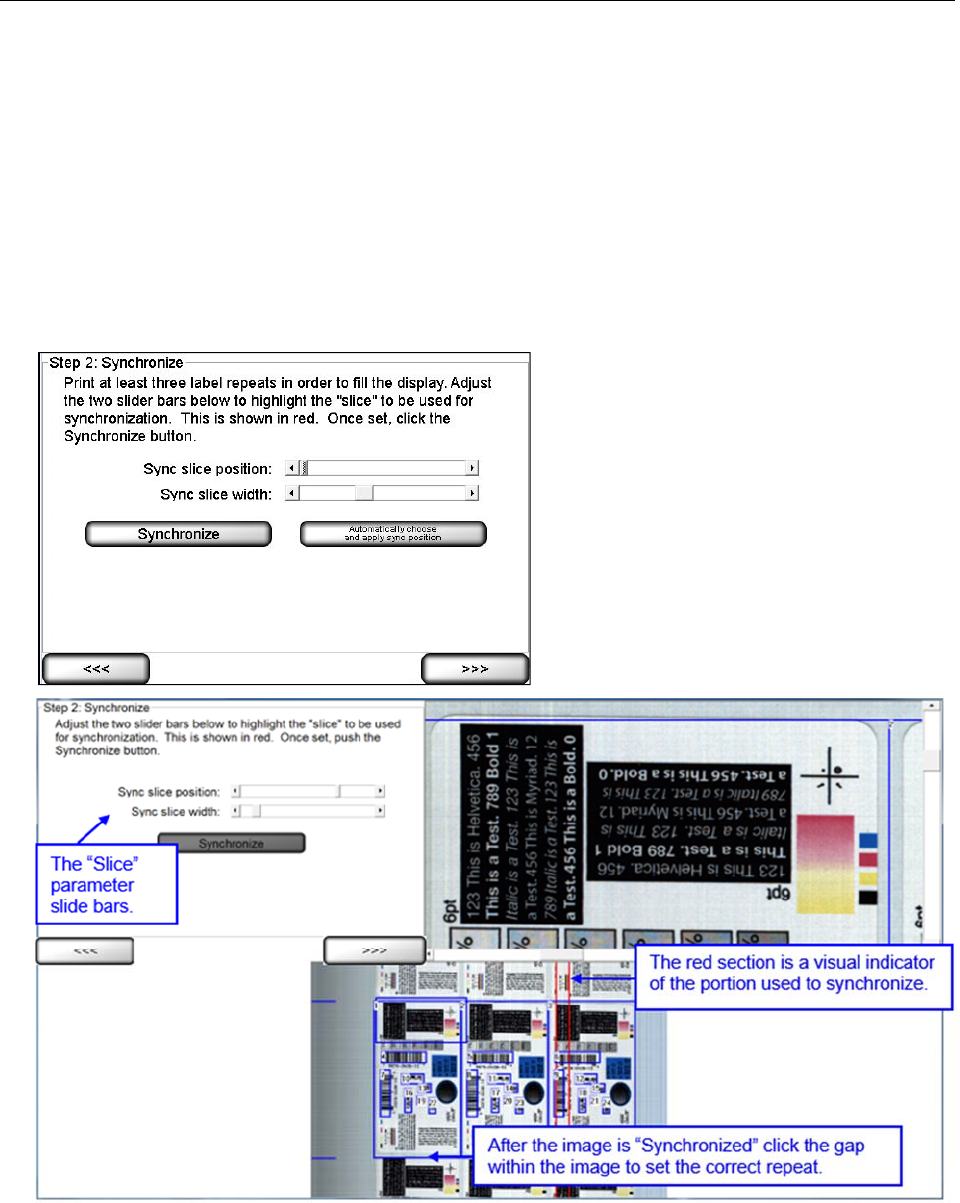
Steps:
1. In order to manually synchronize the system, the operator must adjust the two slide bars. The “slice” is a
portion of the label that has the best representation of the labels static (unchanging) portion. To change
the Width of the “slice” use the “Sync slice width” slide bar. The minimum size is 128 pixels, and the max
is ¼ of the cameras field of view. Next move the “Sync slice position” slide bar to the desired location.
Then, press “Synchronize.”
The system can also perform the above steps automatically to find the best sync position and width.
Click the “Synchronize Automatically” button. The sync slice will be automatically positioned and sized.
Note: The system cannot tell dynamic data from static data on the label. Synchronizing Automatically
can lead to syncing on dynamic data which could lead to poor or inadequate syncing.
There is no limit to the number of times that manual and automatic sync can be performed.
2. To perfectly center the label in the display, point and left-click the mouse in the center of the label gap
shown on the display. The large (full resolution) or the small (full field of view) image can be used. For
very small repeats, the larger image is easier to pinpoint the gap location. Blue hash marks on the side
on the image in 20% and 50% display size must fall in the gaps above and below the label.
3. Click the right arrow button.
LVS-7510 Integrated System Operations Manual Version 20.2.X
LVS-7510 Integrated System Operations Manual Version 20.2.X Page 45 of 210
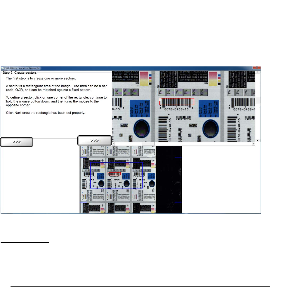
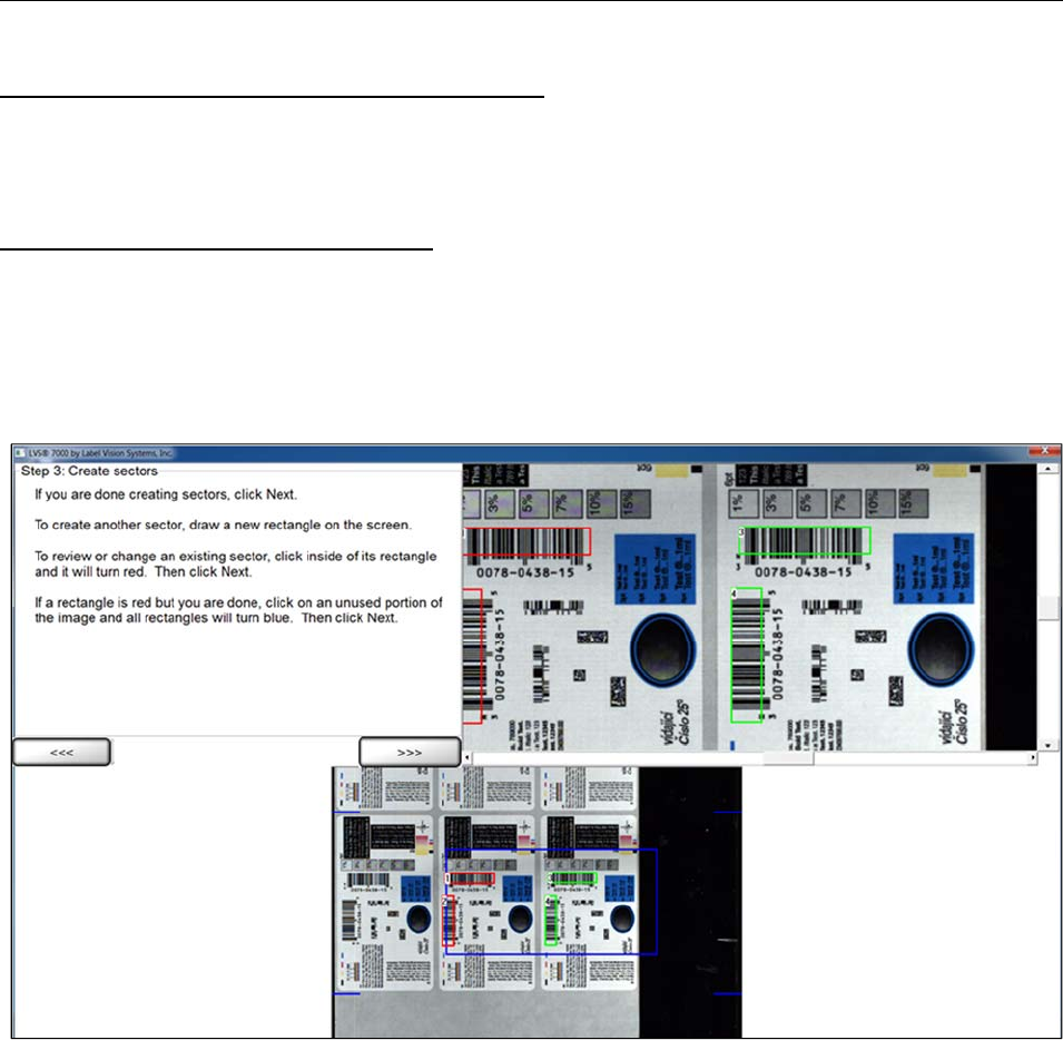
Step 3: Create Sectors
A sector is defined as an area or region of interest that is to be analyzed. This step prompts the operator to
establish a sector. The software will not process anything located outside the sector.
An image must be present to draw a sector. Print several labels and allow them to pass under the camera to
obtain an image. Once an image is acquired, the operator may stop printing and work with the still image.
The above image is an example of a sector being drawn around a barcode. The image shown is in color;
however, the LVS-7510 camera is a grayscale camera only.
Draw a Sector
1. Click on one corner of the area you wish to inspect and drag the mouse while holding down the left-click
button. This action will cause the software to draw a “red” box.
2. After you are satisfied with the sector position and size, click the right arrow button shown on the
display. (Note that a right mouse click does not perform this function.) The box location will not be stored
until the right arrow button has been selected.
Note: The operator may draw a sector in either image.

LVS-7510 Integrated System Operations Manual Version 20.2.X
LVS-7510 Integrated System Operations Manual Version 20.2.X Page 46 of 210
Edit a Sector
1. Using your mouse, click within the desired sector that is located within a blue box; the sector bounding
box then turns red.
2. Click the right arrow button to edit the sector.
3. You will be directed to Step 4 where you define the sector type.
4. After you are satisfied with the sector, click the right arrow button. The box location will not be stored
until the right arrow button has been selected.
Copy an Entire Sector
This option is used to quickly duplicate sector settings for multiple objects of interest within the same label, or
to another label in the same row across the width of the web.
1. Using your mouse, click within the desired sector that is located within a blue box; the sector bounding
box then turns red.
2. Right-click inside the desired sector; the sector bounding box turns green.
3. Drag and drop the selected sector to the desired location; this copies the parameters of the selected
sector.
4. After you are satisfied with the sector, click the right arrow button. The sector location will not be stored
until the right arrow button has been selected.
Note: If you decide not to copy a sector and would like to exit the copying function, simply move
the cursor back to the original sector.
Copy Multiple Sectors
1. Using your mouse, click within the desired sector that is located within a blue box; the sector bounding
box then turns red.
2. Press the Ctrl button on your keyboard while using your mouse to select the additional sectors. Each
selected sector is highlighted in a red box.
3. Right-click on any sector; this causes a green box to appear around each sector.
4. Drag and drop the selected sectors to the desired location.
5. After you are satisfied with the sector, click the right arrow button. The sector location will not be stored
until the right arrow button has been selected.
Note: If you decide not to copy a sector and would like to exit the copying function, simply move
the cursor back to the original sector.
Tip: Use the smallest sector when precisely aligning copied sectors. This allows you to view the
sector’s location more precisely in the full resolution image screen.
LVS-7510 Integrated System Operations Manual Version 20.2.X
LVS-7510 Integrated System Operations Manual Version 20.2.X Page 47 of 210
Shortcuts for Highlighting Multiple Sectors
[Ctrl] + G: Selects all sectors
[Ctrl] + Left-Click: Individually selects multiple sectors
[Shift] + Left-Click: Highlights a range of sectors
Moving Sector(s) with Arrow Keys
Highlight the desired sectors and use one of the actions below.
Arrow keys only: Moves sector(s) by 1 pixel
[Alt] + Arrow Keys: Moves sector(s) by 5 pixels
[Shift] + Arrow Keys: Moves sector(s) by 25 pixels
[Ctrl] + Arrow Keys: Resizes sector(s) in arrow direction
Multiple sectors can be copied and moved to other labels. This is helpful when an operator has to check the
same information on different labels within a repeat. The image shown is in color; however, the LVS-7510
camera is a grayscale camera only.
LVS-7510 Integrated System Operations Manual Version 20.2.X
LVS-7510 Integrated System Operations Manual Version 20.2.X Page 48 of 210
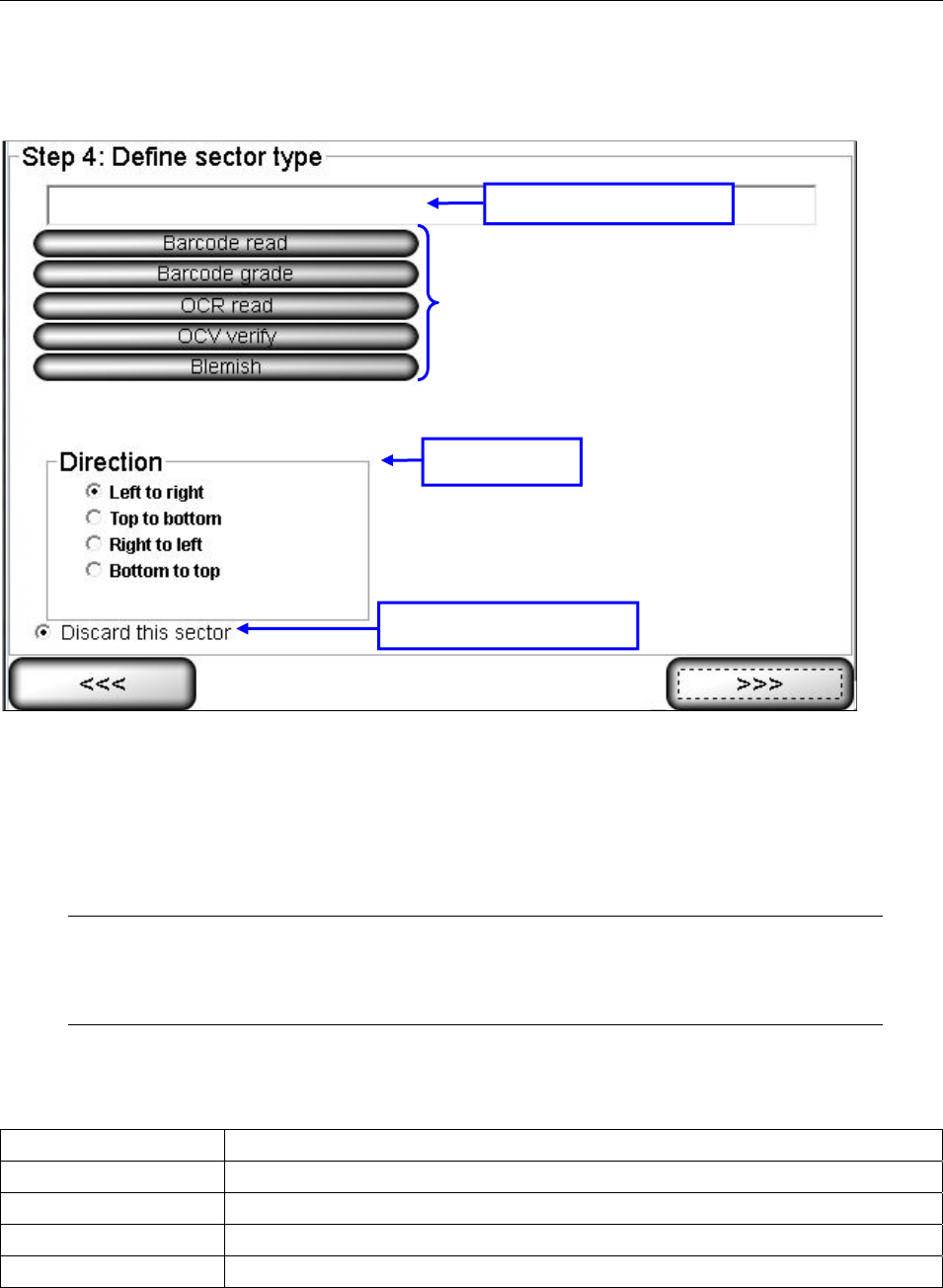
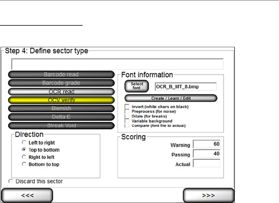
Step 4: Define Sector Type
This step allows you to select the desired sector type that your software is capable of analyzing.
The following sector types are available:
Barcode read
Barcode grade
OCR read
OCV verify
Blemish
Note: The field located above the sector type list pre-populates with the string that the
system is returning for the sector type. For example, if selecting the Barcode read sector
type, the field populates with the decoded string.
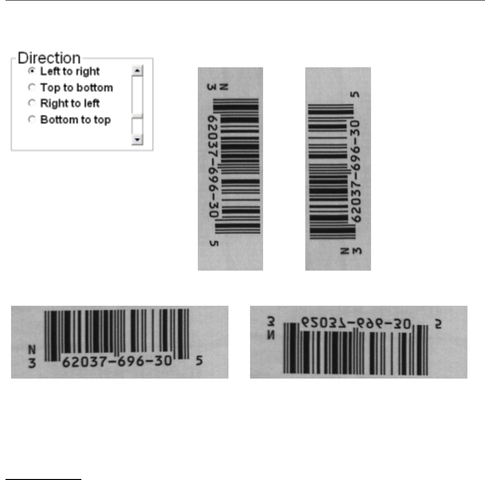
Direction Box
The “Direction” box allows the user to select the orientation in which to read the characters across the
screen. The feature is applicable when using the OCR or OCV modules. Options include:
Direction Description
Left to right Reads characters from left to right. Typically, this is the desired direction.
Top to bottom Reads characters from top to bottom.
Right to left Reads characters from right to left.
Bottom to Top Reads characters from bottom to top.
Displays decoded data
Sector Types
Direction Box
Discard this Sector option
LVS-7510 Integrated System Operations Manual Version 20.2.X
LVS-7510 Integrated System Operations Manual Version 20.2.X Page 49 of 210
Examples:
Top-to-Bottom
Bottom-to-Top
Left-to-Right Right-to-Left
Discard This Sector
If you have incorrectly drawn a sector, click the Discard this Sector button and then select the right arrow
button. The sector is deleted. Sectors can also be removed by hitting the delete key while a sector(s) is
active.
Sector Types
The following is a list of sector types with a description on how to set up a template using that specific sector
type.
LVS-7510 Integrated System Operations Manual Version 20.2.X
LVS-7510 Integrated System Operations Manual Version 20.2.X Page 50 of 210
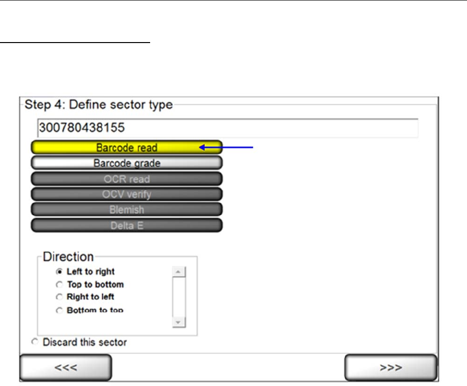
Sector Type 1: Barcode read
This sector is used to validate a 1D or 2D barcode label. The LVS-7510 inspects the barcode image to
determine if it is “readable” by a scanner.
1. Select Barcode read.
2. Select the desired direction. The encoded data is shown in the top left corner of the screen.
3. Click the right arrow button.
LVS-7510 Integrated System Operations Manual Version 20.2.X
LVS-7510 Integrated System Operations Manual Version 20.2.X Page 51 of 210
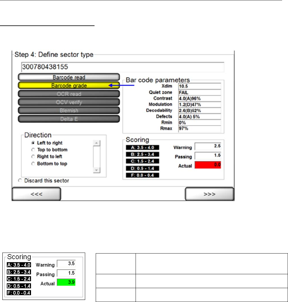
Sector Type 2: Barcode grade
This sector is used when you want to grade the 1D or 2D barcode image according to ISO/IEC standards.
1. Select Barcode grade.
2. Select the desired direction.
3. Choose an acceptable grade in the Scoring box (see below).
4. Click the right arrow button.
Scoring Box
The Scoring box allows you to choose an acceptable grade from 0.0 to 4.0.
Warning Indicates an early warning of diminishing quality in the
barcode image. The operator must take action to
improve the grade score quality.
Passing Represents what ISO/IEC grade is considered to “pass”
and is user-defined to one decimal place.
Actual Represents what grade is being detected using the
setup barcode label.
LVS-7510 Integrated System Operations Manual Version 20.2.X
LVS-7510 Integrated System Operations Manual Version 20.2.X Page 52 of 210
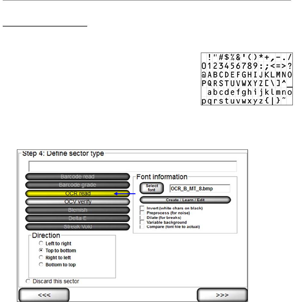
Sector Type 3: OCR Read
This sector type is used to “read” the human readable characters located within the drawn sector.
OCR and OCV Guidelines:
Characters must not touch or overlap
All uppercase letters in any font are allowed
Lowercase letters, uppercase letters, and some special
characters are allowed in OCR-B MT font (6 to 14 points). Shown
to the right are the letters, numbers, and special characters
supported by OCR-B MT font (6 to 14 points)
Monospaced fonts, like OCR-B, are preferred and perform better
in the LVS-7510
Do not attempt to re-learn any of the supplied OCR-B MT fonts
Steps:
1. Select OCR (read).
2. Select the desired direction.
3. Follow the steps below:
a. Select the desired font by choosing one of the options below:
To choose a specific font, click the Select font button and select the desired font.
To create, train and edit fonts, click the Create/Learn/Edit button. See the “Create/Learn/Edit
Fonts” section below for more information.
b. Additional options include:
Invert (white chars on black) tells the sector to look for white characters on a dark
background.
PreProcess (for noise) reduces noise and background contrast variances.
LVS-7510 Integrated System Operations Manual Version 20.2.X
LVS-7510 Integrated System Operations Manual Version 20.2.X Page 53 of 210
Dilate (for breaks) joins characters using a blurring and joining technique; it makes the characters bold
and darker. This option is useful for Dot Matrix-type printing.
Variable background attempts to compensate for text printed on backgrounds that have a gradient or
change from one color to another.
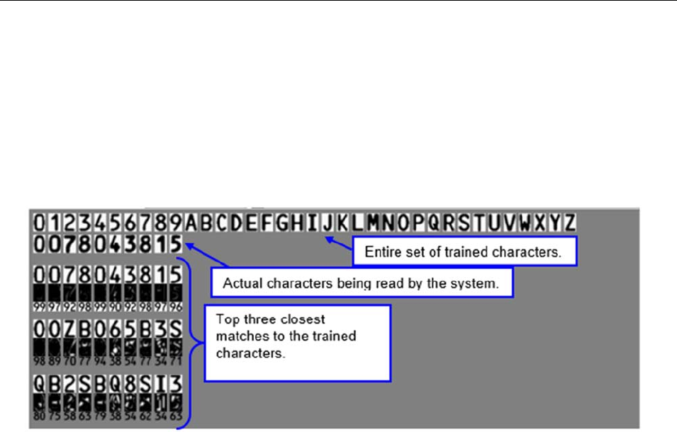
Compare (font file to actual) displays an Actual vs. Font File image in the lower half of the screen. The
image shows the font file across the top of the image and the actual characters within the sector down
the left side. Differences between a font file and an actual character are highlighted in white over black in
the center of the screen. Each character is matched against the font file and given a score. The
character with the highest score is then used as the result.
4. Click the right arrow button.
LVS-7510 Integrated System Operations Manual Version 20.2.X
LVS-7510 Integrated System Operations Manual Version 20.2.X Page 54 of 210
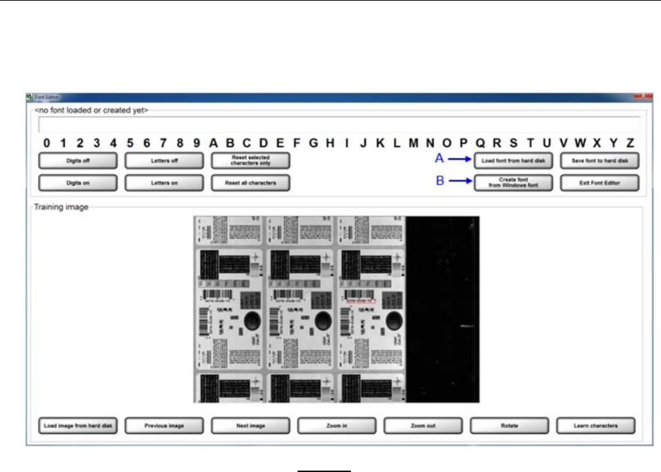
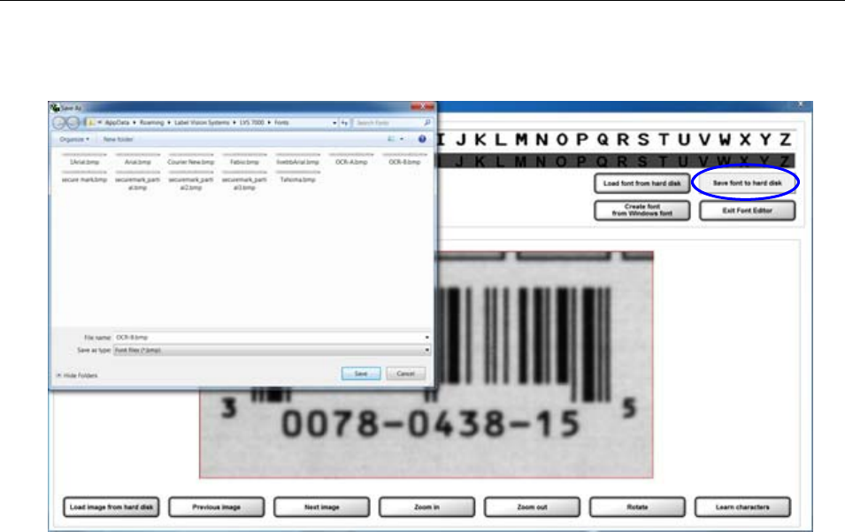
Create/Learn/Edit Fonts:
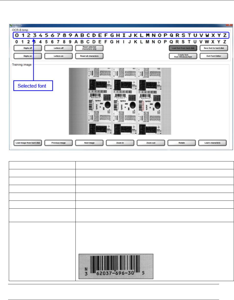
1. Click the “Create/Learn/Edit” button. The Font Editor page appears (see below).
2. The desired font must be loaded or created. DO NOT attempt to re-learn any of the supplied OCR-B MT
fonts.
To load a font from a specific location, click the “Load font from hard disk” button (see “A” in the
above screenshot). Locate the desired font, and then click “Open”.
To create a font using a Windows font, click the “Create font from Windows font” button (see “B” in
the above screenshot). Select the desired font and then click “Ok”.
LVS-7510 Integrated System Operations Manual Version 20.2.X
LVS-7510 Integrated System Operations Manual Version 20.2.X Page 55 of 210
3. The selected font appears in the top text field.
4. Use the buttons at the bottom of the screen to capture the desired image view. Buttons include:
Button Description
Load image from hard disk Click to load an image stored on a hard disk.
Previous Image Click to view the previous image.
Next Image Click to view the next image.
Zoom In Click to view a magnified image of the label.
Zoom Out Click to return to the original image view.
Rotate Click to rotate the image. The image rotates each time the button is
clicked.
Learn Characters Used when training letters or numbers. This button is described in
more detail in the following sections.
Important: An image must be in normal orientation (from left to right,
and right side up) to be used for training (see example below). Use the
Rotate button to rotate the image to the desired view.
Note: Click the “Exit Font Editor” button in the top right corner of the screen to discard changes.
5. An entire alphanumeric string (0-9 and A-Z), or specific digits or letters, can be trained. Read the
sections below for further information.
LVS-7510 Integrated System Operations Manual Version 20.2.X
LVS-7510 Integrated System Operations Manual Version 20.2.X Page 56 of 210
Train an Entire Alphanumeric String:
a. An image comprised of an entire alphanumeric string (0-9 and A-Z) must be present in the training
image view.
b. Use the left click button on your mouse to draw a box around the alphanumeric string in the training
image view.
c. Click the “Learn characters” button. The trained alphanumeric string appears in the top field.
d. When all changes are complete, click the “Save font to hard disk” button. In the window, save the font to
the desired folder.
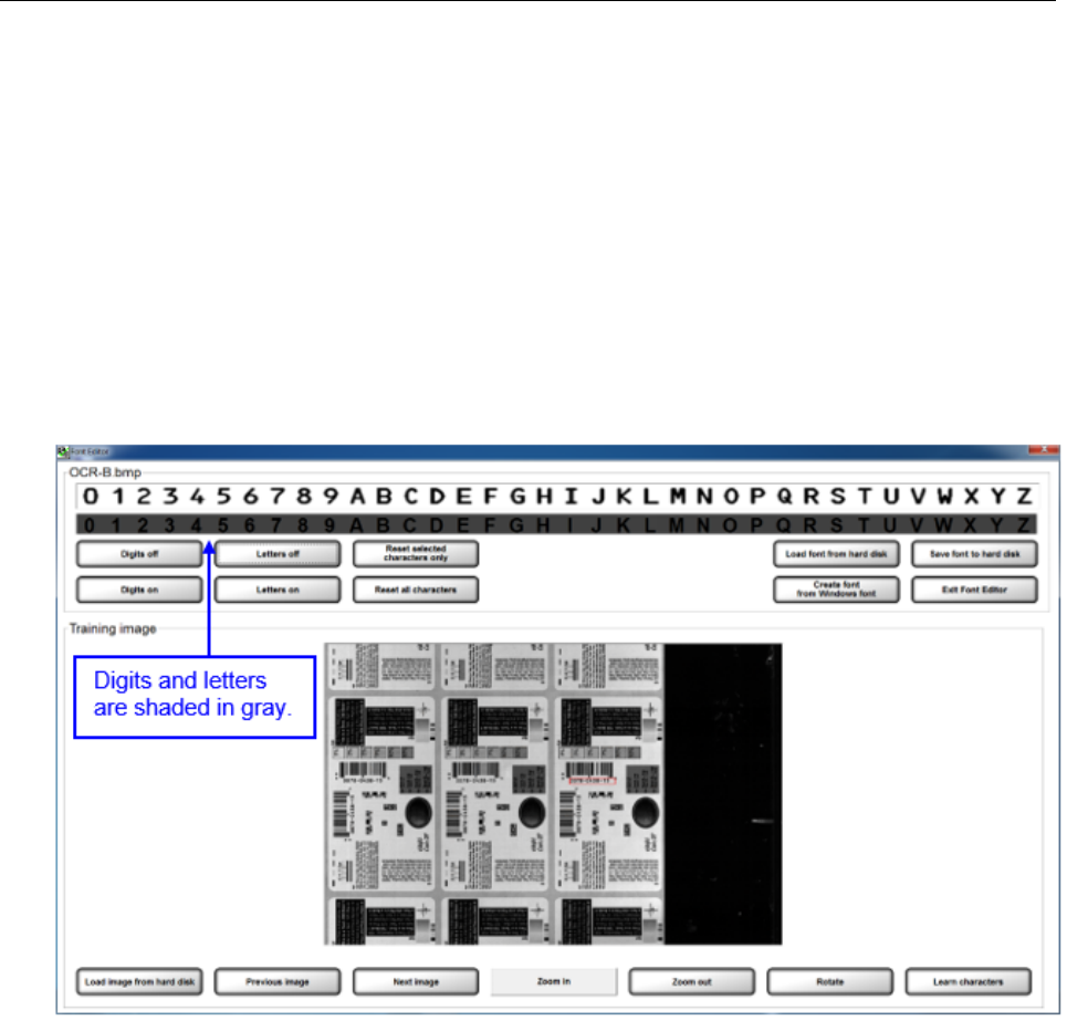
Train Specific Digits or Letters:
a. All digits and letters must be shaded in gray. Do this by selecting the “Digits off” button and “Letters off”
button; this shades all digits and letters.
LVS-7510 Integrated System Operations Manual Version 20.2.X
LVS-7510 Integrated System Operations Manual Version 20.2.X Page 57 of 210
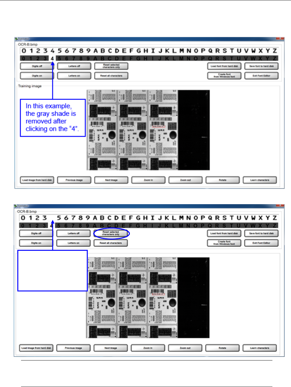
b. Click on the desired digit or letter; the gray shade is removed from the selected digit or letter. See
example below.
c. Click the “Reset selected characters only” button. The character disappears (see below).
Note: If you do not select this button, the software averages the character in the top text
field with the character in the training image.
In this example, the
“4” disappears after
clicking the “Reset
selected characters
only” button.
LVS-7510 Integrated System Operations Manual Version 20.2.X
LVS-7510 Integrated System Operations Manual Version 20.2.X Page 58 of 210
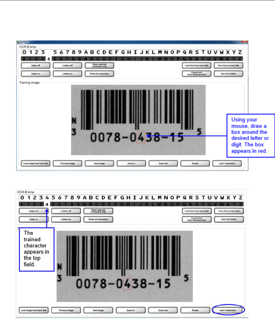
d. Use the left click button on your mouse to draw a box around the letter or digit in the training image
view (see below). Note that the training image in the screenshot below appears larger after clicking the
“Zoom In” button.
e. Click the “Learn characters” button. The trained character appears in the top field (see below).
LVS-7510 Integrated System Operations Manual Version 20.2.X
LVS-7510 Integrated System Operations Manual Version 20.2.X Page 59 of 210
f. When all changes are complete, click the “Save font to hard disk” button. In the window, save the font
to the desired folder (see below).
LVS-7510 Integrated System Operations Manual Version 20.2.X
LVS-7510 Integrated System Operations Manual Version 20.2.X Page 60 of 210
Sector Type 4: OCV Verify
The OCV (Optical Character Verification) sector type is used to score the print quality of the human readable
characters within a drawn sector.
1. Select OCV verify.
2. Select the desired direction.
3. Follow the steps below:
a. Select the desired font by choosing one of the options below:
To choose a specific font, click the Select font button and select the desired font.
To create, train and edit fonts, click the Create/Learn/Edit button. See the section above entitled
“Create/Learn/Edit Fonts” for more information.
b. Additional options include:
Invert (white chars on black) tells the sector to look for white characters on a dark background.
PreProcess (for noise) reduces noise and background contrast variances.
Dilate (for breaks) joins characters using a blurring and joining technique; it makes the
characters bold and darker. This option is useful for Dot Matrix-type printing.
Variable background attempts to compensate for text printed on backgrounds that have a
gradient or change from one color to another.
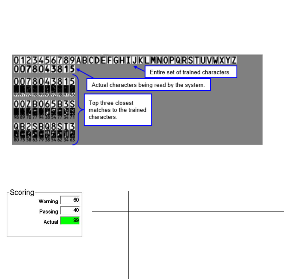
LVS-7510 Integrated System Operations Manual Version 20.2.X
LVS-7510 Integrated System Operations Manual Version 20.2.X Page 61 of 210
Compare (font file to actual) displays an Actual vs. Font File image in the lower half of the screen. The
image shows the font file across the top of the image and the actual characters within the sector down
the left side. Differences between a font file and an actual character are highlighted in white over black in
the center of the screen. Each character is matched against the font file and given a score. The
character with the highest score is then used as the result.
4. Determine a score (see Scoring Box below for additional information) and then click the right arrow
button.
Scoring Box
The OCV Scoring box allows you to choose an acceptable score ranging from 0 to 99.
Warning Indicates an early warning of diminishing print quality.
The operator must take action to improve the grade score
quality.
Passing The Passing number is a threshold setting. All “Actual”
scores greater than the “Passing” score is said to pass
inspection (and vice versa). If the “Actual” score is less
than the “Passing” score, then the inspection has failed
and alarms can be set to alert the operator.
Actual The Actual number represents a percentage of
confidence. A 95 would indicate that there is a good
chance that the characters within the drawn sector are
correct. A 20 would indicate that there is a better chance
that the characters do not match what was intended.
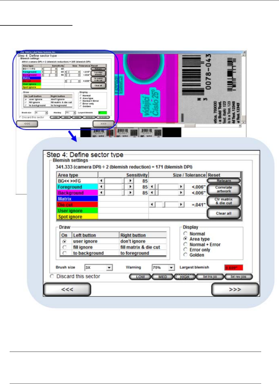
LVS-7510 Integrated System Operations Manual Version 20.2.X
LVS-7510 Integrated System Operations Manual Version 20.2.X Page 62 of 210
Sector Type 5: Blemish
To use the Blemish sector type, follow the steps below.
1. Select Blemish on the Step 4: Define Sector Type screen; the following screen appears.
2. The software automatically learns the first image it sees after the first sector has been drawn. If the
image is not the correct one, or you would like to put a different image into the field of view, click the
Relearn button and the software will accept the next image it sees within that sector. This saved image
is called the “Golden image”. The entire process of understanding blemishes is done by comparing the
“Golden image” to the Job image.
Note: Ctrl+L is a keyboard shortcut for the Relearn button. After pressing Ctrl+L, the system
will accept the next image it sees within each Blemish sector and saves the image as the Golden
image. This shortcut is available only when the system is in Run mode.
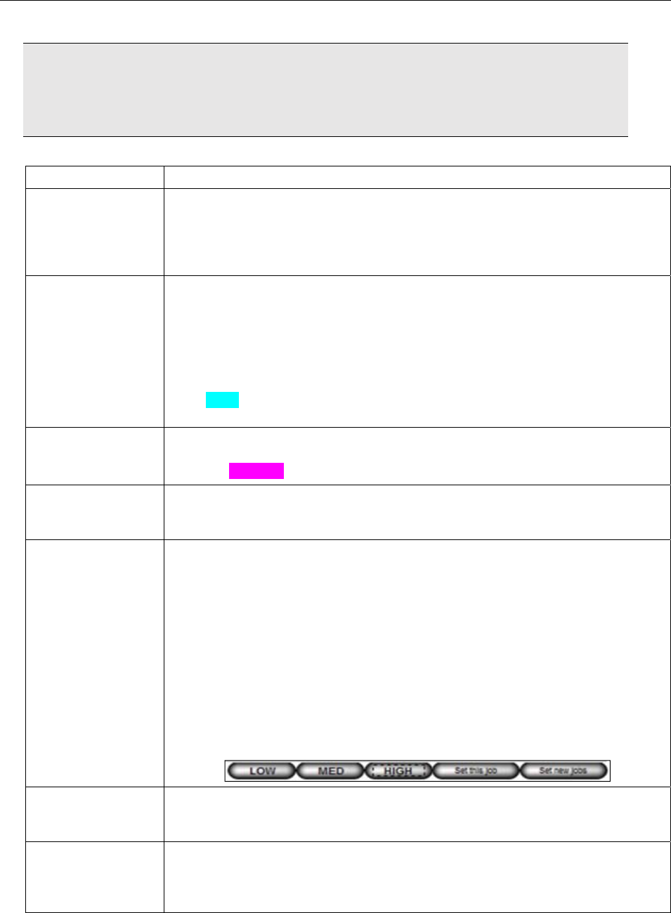
LVS-7510 Integrated System Operations Manual Version 20.2.X
LVS-7510 Integrated System Operations Manual Version 20.2.X Page 63 of 210
IMPORTANT: After pressing Ctrl+L, a popup message will appear for users without
administrative rights. The user must enter an administrator user name and password for the
command to take effect. The golden image that is recorded is the image after the authorized
user name and password is entered.
3. Within the Blemish Settings box (see above), adjust the following fields as needed:
Field Description
BG<< >>FG
<< Background
>> Foreground
Separates the Foreground from the Background. Increasing this number will
define more print as Foreground and less as Background. Decreasing this
number will define more of the label as Background and less as Foreground. A
sensitivity of 0 will call everything Background and 100 will call everything
Foreground.
Foreground
Sensitivity
The Foreground Sensitivity setting is the system’s allowable deviation in print
color contrast after converting to gray scale. A sensitivity of 0 will accept all
variations from the original pixels gray scale value, while 100 will allow no
variation of the gray scale values. In other words, a setting of 0 will pass
everything that is defined as Foreground print and a setting of 100 will pass
nothing. The operator will need to adjust this setting to find an acceptable
value that does not cause false errors in the print. Foreground is shown in the
color Cyan when the Display is set to Area type. Label sections can be sent to
the background or foreground through the Draw tool.
Background
Sensitivity
The Background Sensitivity works the same way as Foreground but it is meant
to find contrast differences in the label’s background. Background is shown in
the color Magenta when the Display is set to Area type.
Size/Tolerance
These settings allow the user to increase or decrease the size of detected
Blemishes. It is important to test the software so that a user understands what
size Blemishes are acceptable.
Preset
Configuration
Settings
The Preset Configuration Settings buttons allow a user to adjust the following
six blemish settings and to apply the settings to a particular job or to all new
jobs created (based on administrator rights). See the “Preset Configuration
Settings” section for more information on using the Preset Configuration
Settings buttons.
BG<< >>FG sensitivity
Foreground sensitivity
Background sensitivity
Foreground Size/Tolerance
Background Size/Tolerance
Die Cut Size Tolerance
Matrix
Matrix detects the roll section between labels to ensure the waste material is
removed. Matrix is shown in Blue when the Display is set to Area type and is
not needed for most label stock.
Die cut tolerance
This setting changes the size of the Red line that wraps around each label
when using “fill here” under the Draw section. This area measures the
movement of the outside edge of the label compared to the printing within for
die movement.
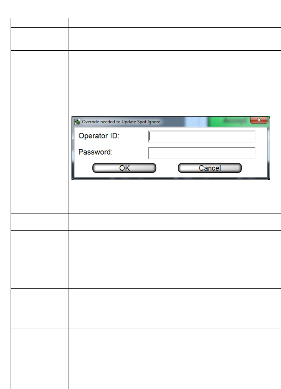
LVS-7510 Integrated System Operations Manual Version 20.2.X
LVS-7510 Integrated System Operations Manual Version 20.2.X Page 64 of 210
Field Description
User ignore
This option is enabled in the Draw section and allows the user to draw green
ignore areas within the Blemish sector. This tool is useful when there is
incrementing data or differences between each label.
Spot ignore Ignore areas appear in yellow when the “Update Spot Ignore” button is used.
This feature is useful for areas of the label that may have frequent deviations
from the reference golden image, where deviations are less critical and the
operator should be given discretion to accept the label. Only operators granted
the Allow Accept / Replace Errors permission are allowed to use the Spot
ignore feature.
When an operator without Administrator permissions clicks the “Update Spot
Ignore” button, the following message appears:
The operator must enter an Administrator’s Operator ID and Password to
continue, or the Spot ignore feature cannot be used. For more information on
permissions, refer to: Welcome Screen Overview Administration
Operators Manage Operator Permissions within the LVS-7510 Software.
Brush Size
Allows the user to change how large or small the brush stroke will be when
ignoring an area.
Warning Select the warning percentage. If the current blemish is less than the Blemish
Size / Tolerance setting and if the ratio of the current blemish size to the
Blemish Size / Tolerance setting is greater than the warning percentage, then
the inspection passes but a warning is flagged.
For example, suppose you decide that a .25” blemish is considered an error. If
the warning percentage is 75%, then a blemish of .25” x 75% = .1875” or larger
is a warning. Blemish sizes less than .1875" is acceptable and passes the
inspection. Blemish sizes .25” and greater will flag an error.
Largest blemish Shows the largest blemish in inches
Discard this sector Click this button to delete the sector. After this button is clicked, the “Step 4:
Define Sector Type” screen appears allowing you to select another sector.
Sectors can also be removed by pressing the “Delete” keyboard button while a
sector(s) is active.
Relearn Button
The Relearn Button will re-train the Golden image with the image that is
present.
Tip: Ctrl+L is a keyboard shortcut for the Relearn button. After pressing
Ctrl+L, the system will accept the next image it sees within each Blemish
sector and saves the image as the Golden image. This shortcut is available
only when the system is in Run mode.
IMPORTANT: After pressing Ctrl+L, a popup message will appear for users
without administrative rights. The user must enter an administrator user name

LVS-7510 Integrated System Operations Manual Version 20.2.X
LVS-7510 Integrated System Operations Manual Version 20.2.X Page 65 of 210
Field Description
and password for the command to take effect. The golden image that is
recorded is the image after the authorized user name and password is entered.
Correlate artwork Click this button to begin the optional PDF Comparator process, which allows
the comparison of PDF artwork to the Omron Microscan golden image for the
actual print job. See Design Mode on page 14 for more details on comparing
PDFs.
Clr matrix & die cut Click this button to clear all matrix and die cut filled sections.
Clear all Click this button to Clear all ignored and auto filled sections within a chosen
sector.
4. The options in the Display box are shown below:
Field Description
Normal Shows the Actual image only.
Area Type This view shows the label using the color codes for each blemish feature.
Normal + Error
This view allows the user to see errors as they occur. The user usually uses
this screen to find the errors, and then goes to the Normal+Ignore screen to
draw the ignore sections.
Error Only
This is a tool for the operator to use in order to understand what the software
views as a difference between the Golden image and the Actual image. When
this option is selected, the image will turn black and errors will be highlighted in
white.
Golden Shows an overlay of the Golden Image over the Actual Image.
5. Click the Global copy button to replicate the setting changes in the same sector across all labels. See
the “Global Copy” section for more information.
6. Click the right arrow button.
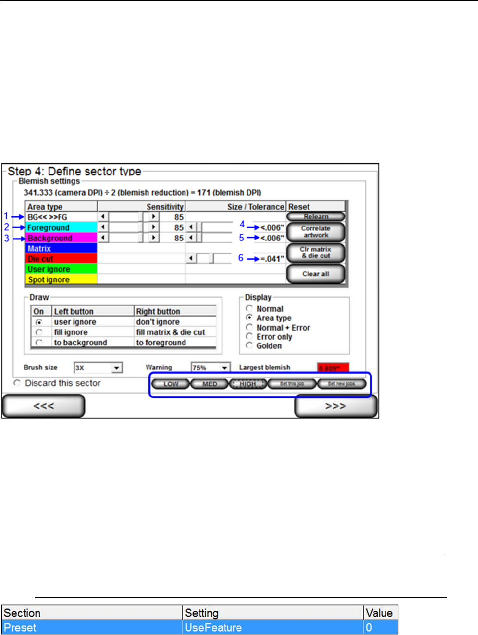
LVS-7510 Integrated System Operations Manual Version 20.2.X
LVS-7510 Integrated System Operations Manual Version 20.2.X Page 66 of 210
Preset Configuration Settings
The preset configuration settings allow a user to adjust the following six blemish settings on the “Step 4:
Define sector type (Blemish settings)” screen:
1. BG<< >>FG sensitivity
2. Foreground sensitivity
3. Background sensitivity
4. Foreground Size/Tolerance
5. Background Size/Tolerance
6. Die Cut Size Tolerance
The functionality of the preset configuration settings vary based on user permissions.
Users with administrator rights can configure the preset configuration settings and apply the settings to a
particular job or to all new jobs created. For more information on permissions, refer to: Welcome Screen
Overview Administration Operators Manage Operator Permissions within the LVS-7510
Software.
Users without administrator rights cannot configure preset configuration settings and can only select the
“Low,” “Medium,” and “High” preset buttons to adjust the blemish settings on the “Step 4: Define sector
type (Blemish settings)” screen.
See the sections below for more information on configuring and using the preset configuration settings.
Note: The preset configuration settings buttons are enabled in the “Settings” menu >
[Preset] section > UseFeature setting:
UseFeature=0 (default) – Disables the preset configuration settings buttons
UseFeature=1 – Enables the preset configuration settings buttons
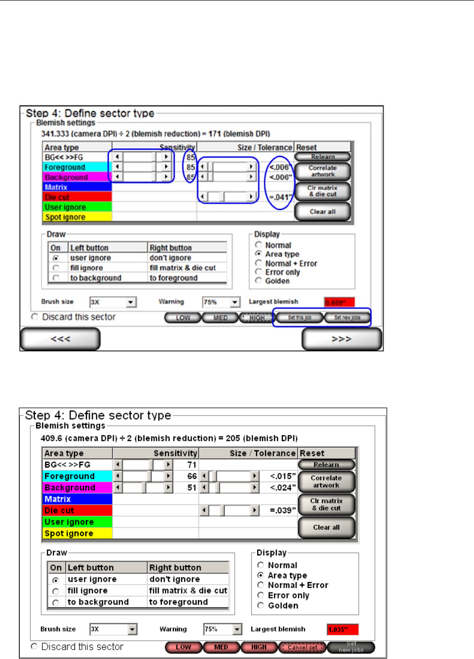
LVS-7510 Integrated System Operations Manual Version 20.2.X
LVS-7510 Integrated System Operations Manual Version 20.2.X Page 67 of 210
Configure the Preset Settings:
Follow the steps below to configure the blemish settings for the low, medium and high preset configuration
settings. Only users with administrator rights can configure the preset configuration settings.
1. Use the slider bar to adjust the sensitivity or size/tolerance settings for the foreground, background, and
die cut settings.
2. When settings are complete, click either the “Set this job” button to apply the settings to only that job, or
click the “Set new jobs” button to apply the settings to all new jobs created. These buttons appear only to
users with administrator rights.
3. The preset buttons (Low, Medium, High) turn red.

LVS-7510 Integrated System Operations Manual Version 20.2.X
LVS-7510 Integrated System Operations Manual Version 20.2.X Page 68 of 210
Click “Low” to apply the blemish settings to the low preset configuration setting.
Click “Med” to apply the blemish settings to the medium preset configuration setting.
Click “High” to apply the blemish settings to the high preset configuration setting.
Click the “Cancel set” button to cancel the blemish configuration settings.
4. Follow the above steps to set the configuration settings for each of the present configuration buttons
(Low, Medium and High).
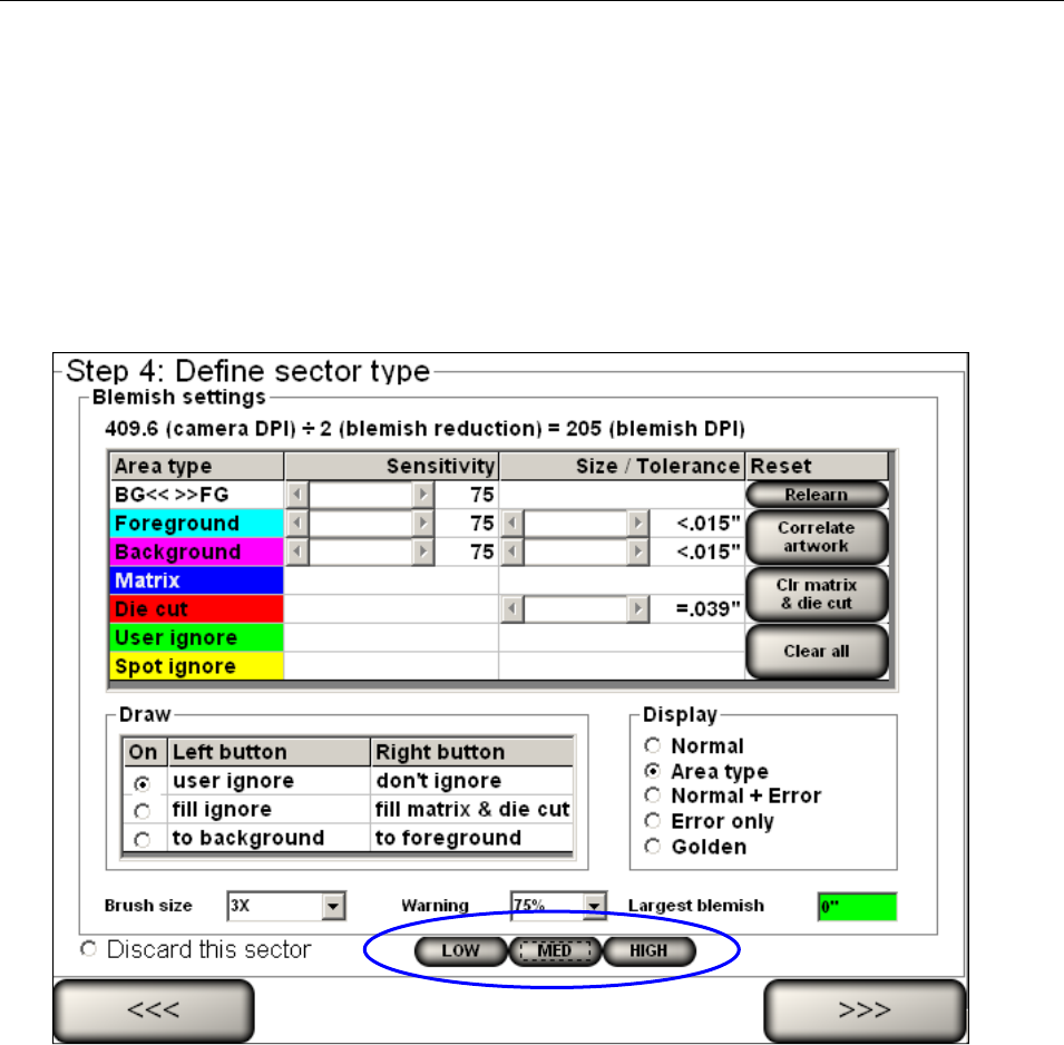
LVS-7510 Integrated System Operations Manual Version 20.2.X
LVS-7510 Integrated System Operations Manual Version 20.2.X Page 69 of 210
Use the Preset Settings:
Users without administrator rights can select the “Low,” “Medium,” and “High” preset buttons to view the
image(s) on the “Step 4: Define sector type (Blemish settings)” screen.
Click “Low” to adjust the blemish settings to the “Low” configuration settings as defined by a user with
administrator rights.
Click “Med” to adjust the blemish settings to the “Medium” configuration settings as defined by a user
with administrator rights.
Click “High” to adjust the blemish settings to the “High” configuration settings as defined by a user with
administrator rights.
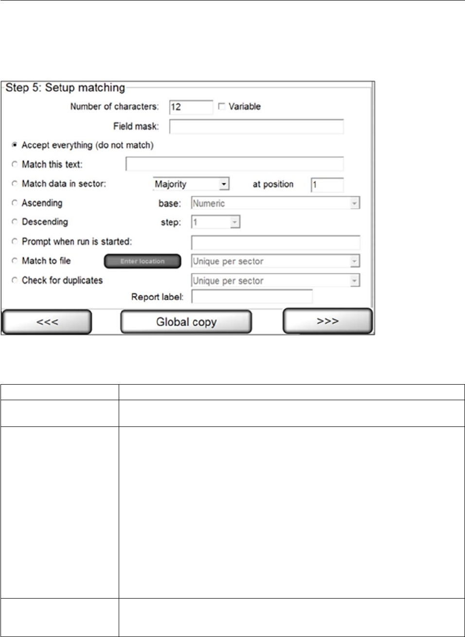
LVS-7510 Integrated System Operations Manual Version 20.2.X
LVS-7510 Integrated System Operations Manual Version 20.2.X Page 70 of 210
Step 5: Setup Matching
Step 5: Setup Matching is used to set up sequential, matching or incremental information checking. This step
does not apply to Blemish modules.
Complete the applicable fields and then click the right arrow button. Each field description is listed in the
table below. The software reverts back to STEP 3 prompting you to set up another sector if desired. If
another sector is not required, click the right arrow button and proceed with the next step.
Field Description
Number of characters Ensure the number of characters is correct for the string length or a “Wrong
Length” error will constantly be encountered.
Field Mask Teaches the sector what type of character to expect for each position within a
string. There are three possibilities for each character: numeric (#), alphabetic
(@), and alpha/numeric (*). Special characters can also be used by typing the
exact character in the position where it will be present.
The following informational format is to be used:
Sample: = (AB)8C23 = (@@)*@##
@ means 'A' to 'Z'
* means 'A' to 'Z' or '0' to '9'
# means '0' to '9'
( ) means ' (' and ') ' - Any characters that are not @ * # are assumed to be
special characters.
IMPORTANT! Do not include a space inside the mask. Also, OCR/OCV can
handle up to 39 characters and an error will occur if there are more than 39
characters in the field mask box.
Accept everything (do
not match) If sequential or matching checking is not required, click the Accept
everything (do not match) option and leave all other options on this page
alone. This option will be grayed out when using OCV.

LVS-7510 Integrated System Operations Manual Version 20.2.X
LVS-7510 Integrated System Operations Manual Version 20.2.X Page 71 of 210
Field Description
Match this text To match a static (unchanging) number, select Match this text and enter the
desired string into the text box.
Match data in sector If you are using multiple sectors, you may wish to match the data in one
sector to the data in another sector. To accomplish this, select Match data in
sector and choose the desired sector from the drop-down list of previously
trained sectors.
The Majority feature looks at all sectors that are set to majority, takes the
most popular result, and then matches the sectors to that popular result.
The At Position feature tells the software where to start reading data within a
sector.
Take the string A1234 as an example, if you change at position to 3 then the
software will only read 234.
The Global copy feature will copy the logically located sector as compared to
the original “From” and “To” sectors’ positional relationship.
Refer to the diagram below in the “Global Copy Diagram” section.
Ascending or
Descending When checking sequential data, you must select Ascending or Descending.
If the numbers are incrementing by a different amount, you can select
the amount to increment in the Step list box.
If the sequence is a combination of alpha and numeric, then select the
Base numbering system.
Prompt When Run is
Started
When selected, this feature allows a “Match this text” string to be entered by
the operator at the time of starting a run, allowing the “Match To” text to be
changed without allowing job editing to that operator’s permissions.
When this option is selected the system will prompt at run time for the “Match
to” string. Enter the string in the available text field. Note that each sector is
labeled accordingly. Data can be entered either using a qwerty keyboard or a
bar code scanner with data input mapped to that field using a “keyboard
wedge.”
Match to File This feature compares the data decoded within a sector to the data on a file
created by the user. Options include:
Duplicates allowed – The system allows for repeated data within the
same sector and/or file.
Unique per sector – The system does not allow any repeated data within
the same sector and/or column within a file.
Unique per job – The system does not allow any repeated data within
the same sector and/or file.
See the Match to File section below for additional details about this feature.
Click Enter Location to select the location of the file being matched.
Check for Duplicates Checks data for any duplicates.
Options include:
Unique per sector – The system does not allow any repeated data within
the same sector.
Unique per job – The system does not allow any repeated data within
the same sector or job.
Report Label Use this field to enter a report label, such as a name for the sector. The name
entered in this field appears on the Summary Report and acts as a unique
user-defined identifier of that particular sector. This field is not available for
Blemish sectors.
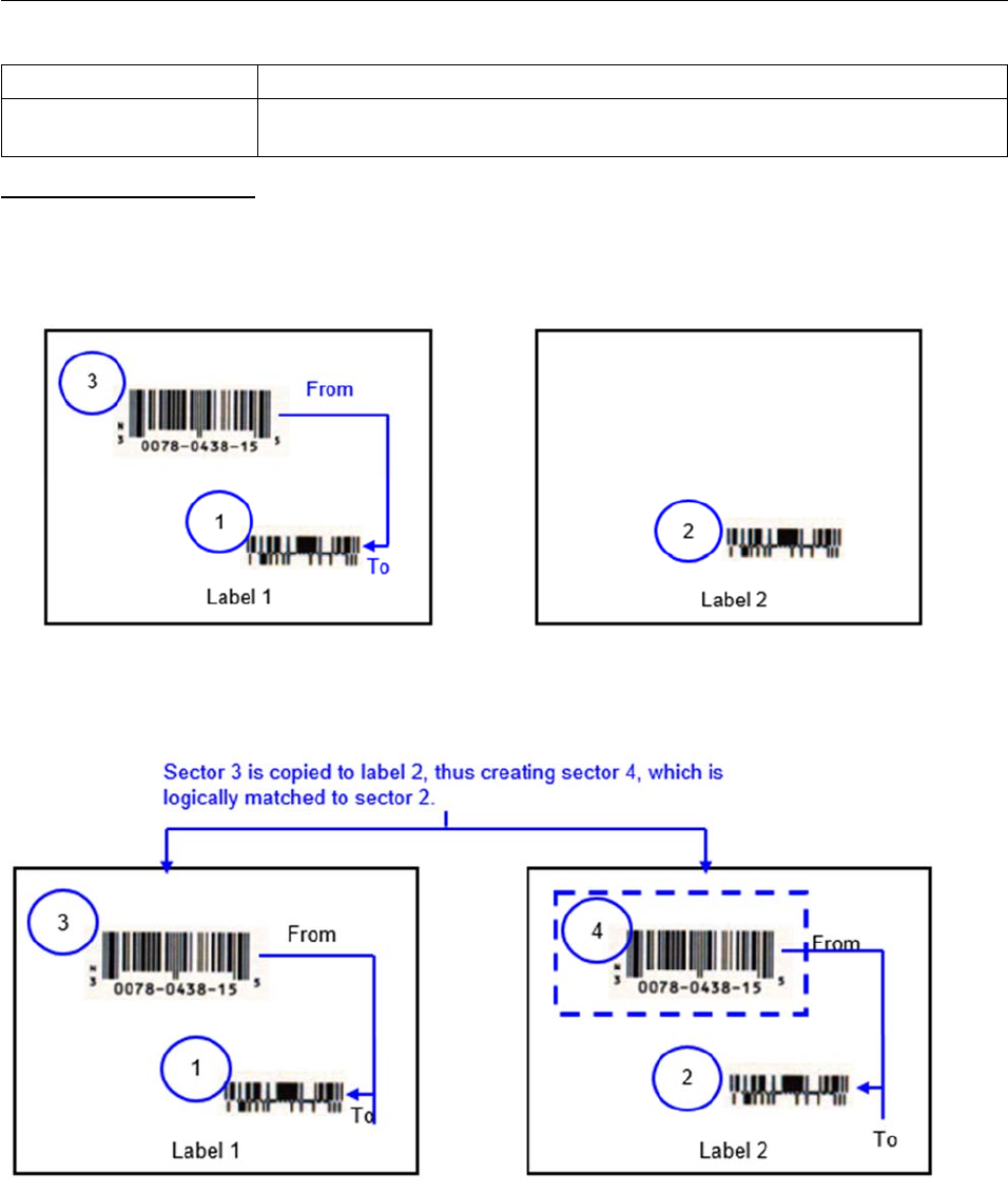
LVS-7510 Integrated System Operations Manual Version 20.2.X
LVS-7510 Integrated System Operations Manual Version 20.2.X Page 72 of 210
Field Description
Global Copy Click the Global copy button to replicate the setting changes in the same
sector across all labels.
Global Copy diagram
Labels BEFORE Global Copy
In Label 1 below, sector 3 is matched to sector 1.
In Label 2 below, there are no sectors matched to sector 2.
Labels AFTER Global Copy
After sector 3 is copied to Label 2, sector 4 is created and matched to sector 2, which is the logically
located sector as compared to the “From” and “To” sectors’ relationship in Label 1.
LVS-7510 Integrated System Operations Manual Version 20.2.X
LVS-7510 Integrated System Operations Manual Version 20.2.X Page 73 of 210
Match to File
This feature compares the data decoded within a sector to the data on a file created by the user. Note that
the format of the file must be a comma-separated values (CSV) file.
Any number of sectors can be set to use “match to file”. If all “Match to file” sectors are marked as
“Duplicates allowed,” the system will not be able to relocate within the data file if stopped during a run. This
means the LVS-7510 is not able to automatically find its place within a run on a job if stopped and restarted.
If this occurs, you must access your file and make the first number in the file be the first expected number in
the camera’s field of view after pressing the run button. The associated hash files within the job heading
must be deleted so they can be recompiled at run time.
IMPORTANT: The “Match to file” feature has associated processing overhead; thus, it is
recommended to review all your options and use the “Match to file” feature as a last resort.
Note: You must create the file to “Match To” on a per job basis. Tools are not provided in
the LVS-7510 software to accomplish this.
The format of the file must be as follows:
The format of the file must be a comma-separated values (CSV) file.
The order in which the data is stored is matched to the sector number in lowest to highest order that has
been selected to “Match to file”.
Headers are not allowed.
Example 1:
In the sample below, the LVS-7510 would expect to have two sectors per repeat that are “Matching to File”.
The file would show that it expects only 11 repeats of the label. Neither sector is expected to have
duplicates. Due to the processing overhead of “Matching to File”, the second sector could be set to perform a
sequential check instead of “Matching to File”.
01111110, 11111110
01111117, 11111111
01111120, 11111112
01111142, 11111113
01111137, 11111114
01111101, 11111115
01111129, 11111116
01111138, 11111117
01111199, 11111118
01111172, 11111119
01111122, 11111120
Example 2:
In this sample, the LVS-7510 would expect to have two sectors per label repeat that are “Matching to File”.
As with the above sector, only 11 repeats of the label are expected; however, the second sector has
duplicates. The LVS-7510 has processing penalties for “Matching to File”. Thus, with this example, it would
be more cost effective to match only the first sector to a file, as the second sector can be set to a fixed match
string without the extra processing required.
01111110, 11111110
01111117, 11111110

LVS-7510 Integrated System Operations Manual Version 20.2.X
LVS-7510 Integrated System Operations Manual Version 20.2.X Page 74 of 210
01111120, 11111110
01111142, 11111110
01111137, 11111110
01111101, 11111110
01111129, 11111110
01111138, 11111110
01111199, 11111110
01111172, 11111110
01111122, 11111110
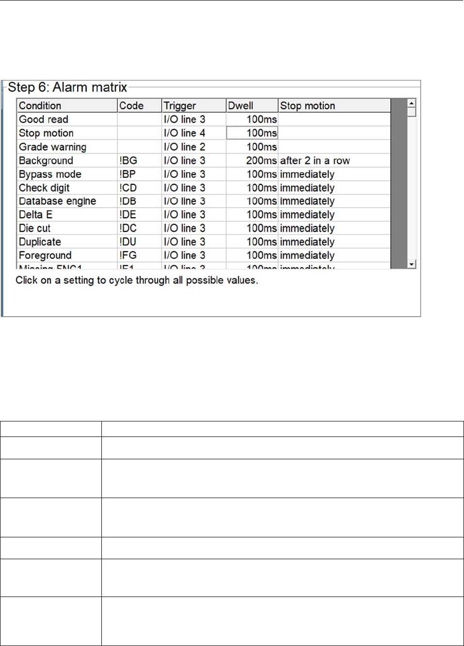
LVS-7510 Integrated System Operations Manual Version 20.2.X
LVS-7510 Integrated System Operations Manual Version 20.2.X Page 75 of 210
Step 6: Alarm Matrix
The Alarm Matrix displays error-specific I/O information. After all sectors have been established, you are
prompted to determine an error condition.
Depending on the supplied hardware, the following relay outputs can be triggered by any of the listed error
conditions:
Line 1 Connected to the green light indicating a “good read.” It is not connected to a relay
Line 2 Connected to the yellow light. It is not connected to a relay
Line 3 Connected to the red light and a relay
Line 4 Connected to the Stop Motion relay
The 5 columns on this screen are listed below:
Column Description
Condition Lists the various error conditions that the system can detect.
Code Lists the abbreviation of the error conditions detected by the system and used
throughout the final reports. See the section below entitled “Error Code
Definitions” for more information.
Trigger Lists any of the four Input/Output lines. Any listed error condition can be trained
to activate any I/O line by clicking on the appropriate row box; this will change the
path to another line. You can also choose “None”.
Dwell Lists the duration of the output signal. You can choose from “10 ms” to “hold”.
Stop Motion States when to activate the “Stop Motion” error condition. You can choose to stop
immediately or to not stop at all. Or, you can choose to stop after a certain
number of errors occur contiguously (from 1 to 10 errors in a row).
Stop Motion Delay
in Inches This is a set distance that the LVS-7510 will output the stop motion signal. It has
a minimum of 4” beyond where the readhead is looking. This is used for precision
placement of found errors and may increase if a high processing workload is
present.

LVS-7510 Integrated System Operations Manual Version 20.2.X
LVS-7510 Integrated System Operations Manual Version 20.2.X Page 76 of 210
Error Code Definitions
With the exception of “Good Read” and “Grade Warning,” all error conditions listed below can be made to
trigger the Stop Motion Relay immediately, or after a predetermined number of consecutive errors.
Error Code Definition
N/A Good Read When the system is triggered, the camera takes a picture of the label. The
system reads all sectors within the image and compares to the associated
sector data in the data file. Any sectors that match are a Good Read. The
system logs to the report the data read from each sector with no error
codes attached.
N/A Stop Motion This output is used as a special output that is sent at a fixed distance
beyond the located error.
N/A Grade Warning
This output is used most commonly for the yellow light. It is triggered in
conjunction with !QU (quality errors). When something fall into the quality
warning zone this output is activated.
!BG Background
This is a blemish error. The background is defined in the blemish sector
setup. This means it is in the background portion of the sector.
!DC Die Cut
Die Cut checks the print as compared to the outside edge of the label to
track how much it moves.
!DU Duplicate
!DU appears when the character string has been read before in the job that
you are running. The Check for Duplicates option in the Matching screen
will enable this error.
!FG Foreground
This is a blemish error. The foreground (!FG) is defined in the blemish
sector setup. This means it is in the foreground portion of the sector.
!GP Gap
When the system is triggered, the camera takes a picture of the label. The
system does not read any of the sectors within that image. The system
does not continue to increment the next expected record within the data
file. The system logs to the report the !GP error code to the associated
data.
!MX Matrix Matrix searches the areas between labels for unstripped waste.
MM! Mismatch
When the system is triggered, the camera takes a picture of the label. The
system reads all sectors within the image and compares to the associated
Job/Sector data in the data file. One or more sectors do not match to what
the Job/Sector settings dictate that it should be. The system logs to the
report the data read from each sector attaching the MM! error code to the
associated sector's data.
Mismatch only applies when comparing the data to a match source. If
running a Sequential type match, then a Mismatch error will be reported as
a Sequence error.
!F1 Missing FNC1 Checks barcode sectors for the presence of FNC1, the Unique GS1
Identifier in the first position.
!NA Not Assessed
The incoming data is not being assessed due to a separate error.
!NS Not Synced
The system has lost synchronization, and is therefore not processing any
data outside of looking for a re-sync lock. It will auto log this run portion as
“requested to splice”
!NR No Read
When the system is triggered, the camera takes a picture of the label. The
system does not read/decode one or more sectors within the image. The

LVS-7510 Integrated System Operations Manual Version 20.2.X
LVS-7510 Integrated System Operations Manual Version 20.2.X Page 77 of 210
Error Code Definition
system compares to the associated Job/Sector data in the data file. The
system logs to the report the data read from each sector attaching the !NR
error code to the associated sectors' data.
!QU Quality
When the system is triggered, the camera takes a picture of the label. The
system reads all sectors within the image. The system compares to the
associated Job/Sector settings in the data file. If one or more
characters/barcodes within a sector are found to be outside the pre-
determined acceptable quality threshold, then the repeat is marked as an
error and displayed in red in the log file. The actual score is appended to
the end of the read data.
!RG Range
The associated data file is loaded the system then reads the first and last
record in the sequential data file. The system stores these values. When
the system is triggered the camera takes a picture of the label. The
system reads all sectors within the image. The system compares to the
associated record in the data file. Not only did the record not match the
data file, but it was also out of the range of numbers that the data file
contains. The system logs to the report the data read from each sector
attaching the !RG error code to the associated sector's data.
!CD Check Digit On 1D barcode sectors only, a MOD 10 check digit algorithm can be
activated. The MOD 10 algorithm uses a simple checksum formula to
validate numbers encoded in a variety of 1D barcode symbologies.
MOD 10 is intended to protect against mistyping errors and scanning
errors.
!SQ Sequence
When the system is triggered, the camera takes a picture of the label. The
system reads all sectors within the image. The system compares to the
associated Job/Sector in the data file. One or more sectors are found to be
out of numerical sequence as compared to the associated record in the
data file. The system logs to the report the data read from each sector
attaching the !SQ error code to the associated sector's data.
Sequence only applies when comparing the data to a known sequence of
numbers. If running a Mismatch type match, then an error in Sequence will
be reported as a Mismatch error.
!WL Wrong Length
When the system is triggered, the camera takes a picture of the label. The
system reads all sectors within the image. The system compares to the
associated Job/Sector data in the data file. One or more sectors do not
match to the specified length of the character string that the Job/Sector
settings dictate that it should be. The system logs to the report the data
read from each sector attaching the !WL error code to the associated
sector's data.

LVS-7510 Integrated System Operations Manual Version 20.2.X
LVS-7510 Integrated System Operations Manual Version 20.2.X Page 78 of 210
Common Causes for Error Conditions
Error Condition Possible Cause
Mismatch
The data read did not match to what was expected to be read. This can be caused
by poor quality of print causing the system to identify one or more characters as
good quality, yet still incorrect. It could also be caused by a character being gone.
Either not printed, or somehow has gone outside the sector borders within the
image.
No Read
The data within a sector was not read at all. This can be caused by missing print,
poor contrast of print, or the expected data was outside of the sector borders
within the image.
Quality
The character(s) within a string do not qualify to the standard entered into
the OCV Threshold, or the barcode grade is not above the minimal passing score
allowed. This can be caused by missing character portions, bad line definition of
characters, or stretched/skewed characters, or any of the ISO/ANSI barcode
grading parameters being below the acceptable level entered in the “PASS if
ACTUAL >=” sector setting parameters.
Sequence
The data does not match to the previous number +/- one. This is most often
caused be a miscommunication that causes one or more numbers within a
sequence to be skipped or repeated, an unconnected RS-232 cable, or user error
on starting number.
Range
The read number is larger or smaller than the file covers. This is usually caused
by the incorrect data file being loaded to compare to.
GAP
No data was discernible in any sector. Most common causes are blank media
coming through the line, or an erroneous triggering mechanism.
Wrong Length
For barcode reading the code has too many/few characters encoded. This could
be from the incorrect code being printed, or the trained in length for the job was
incorrectly set. For OCR/OCV characters the same conditions apply, with the
addition of the possibility of characters being broken or touching. If a broken
character is seen, then one character will become two. If two characters are
touching, they will become one combined character. Also be sure that no
characters are touching the sector box. The system will ignore any characters that
touch the sector box.
Not Assessed Printer is going faster than what the Camera and PC can handle. LinesperInch or
Camera MaxSpeed may be incorrectly set in the “Settings” menu (these settings
must be changed by an Omron Microscan representative only).
Duplicate Character string has previously been seen in this job.
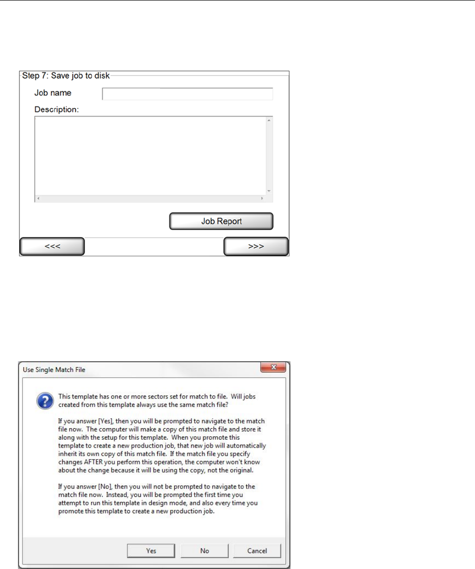
LVS-7510 Integrated System Operations Manual Version 20.2.X
LVS-7510 Integrated System Operations Manual Version 20.2.X Page 79 of 210
Step 7: Save Job To Disk
1. Enter a template name in the Job Name field.
2. If desired, enter a description or additional job details in the Description field.
3. If desired, click the Job Report button to generate an LVS-7510 Job Report which shows the settings for
all created sectors. See the next section entitled “LVS-7510 Job Report” for more information on the Job
Report.
4. Click Next; this saves the current setup.
5. When a new template is saved the first time and Step 5: Setup matching includes a Match to file, the
designer will be prompted with the following message: Design Mode – Template Match to File Selection.
6. The Ready to Run screen appears. See the "Design and Production Mode: Running" section for more
information on this step.
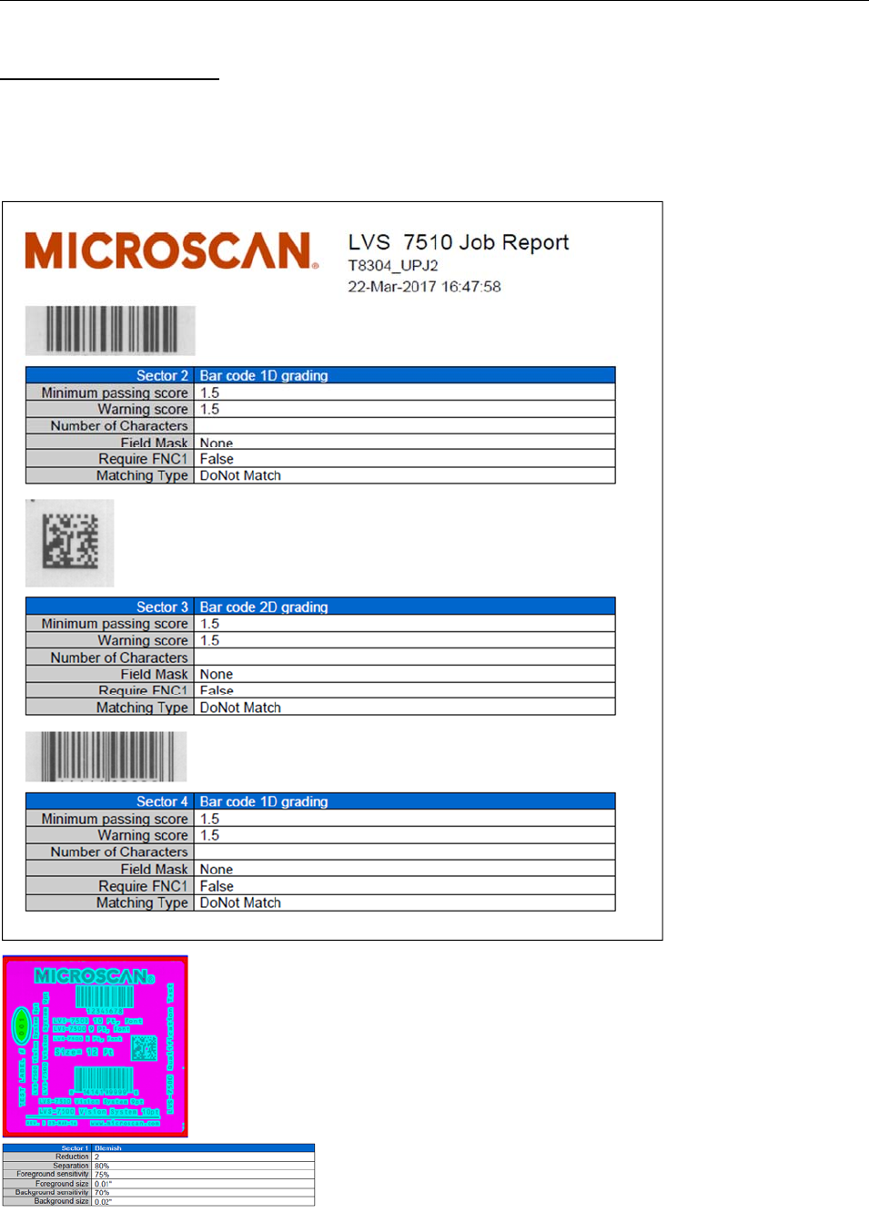
LVS-7510 Integrated System Operations Manual Version 20.2.X
LVS-7510 Integrated System Operations Manual Version 20.2.X Page 80 of 210
LVS-7510 Job Report
The LVS-7510 Job Report shows the settings for all created sectors.
The LVS-7510 Job Report appears when configured for HMTL only in Internet Explorer, Firefox or Chrome
web browsers; no other web browser is supported. Alternately, the Job Report can be configured to create a
.pdf report.
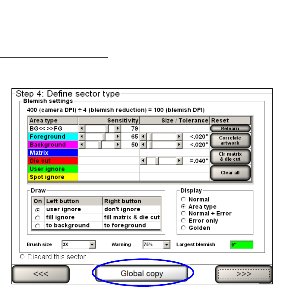
LVS-7510 Integrated System Operations Manual Version 20.2.X
LVS-7510 Integrated System Operations Manual Version 20.2.X Page 81 of 210
Global Copy
The Global Copy feature allows you to replicate the setting changes in the same sector across all labels.
Global copy works with Automatic or Manual setup.
Location of Global Copy button
The “Global Copy” button is visible on the following screens:
When using the Blemish sector type, the Global copy button is visible on the “Step 4: Define Sector
Type” screen (see below).
Global copy button when using the Blemish sector type.
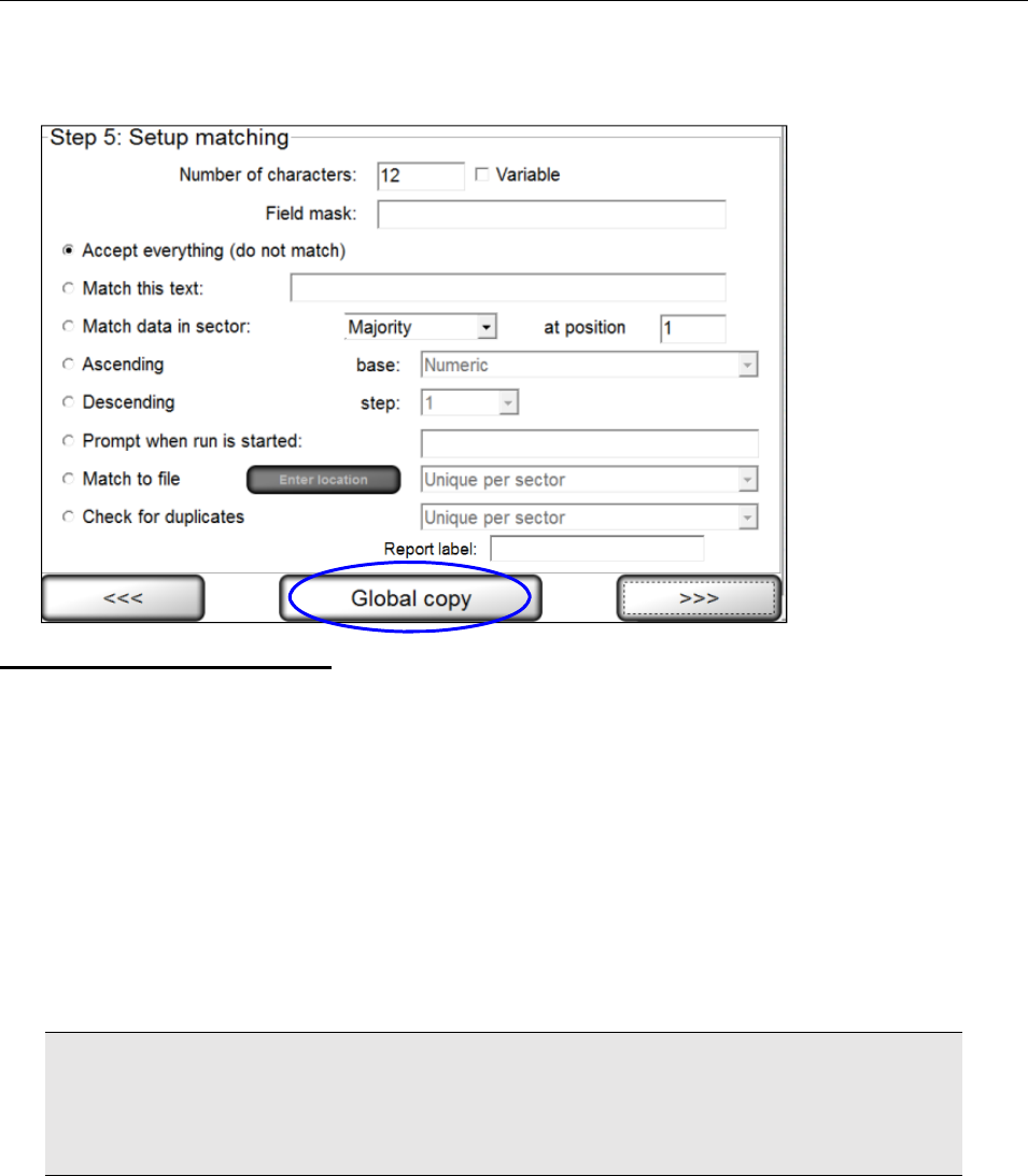
LVS-7510 Integrated System Operations Manual Version 20.2.X
LVS-7510 Integrated System Operations Manual Version 20.2.X Page 82 of 210
For all sector types other than Blemish, the Global copy button is visible on the “Step 5: Setup
Matching” screen (see below).
Global Copy Requirements
The Global copy button appears only if:
There is more than one label per repeat.
There are at least two sectors.
There is at least one pair of comparable sectors (same sectors in different lanes)
The user is on the final step of setting up the sector type.
To define comparable sectors (the same sectors in different lanes), the sectors must:
Have the same sector type (such as Barcode Read, etc)
Have the same width (within 20 pixels)
Have the same height (within 20 pixels)
Have the same distance from the top of the label (within 20 pixels).
IMPORTANT: A simple solution to meet the above requirements is to copy and paste the first
sector to the second sector. For steps on copying sectors, see section “Copy an Entire Sector”
(Design Mode: Create a New Template Create a Template Using Manual Setup Step
3: Create Sectors Copy an Entire Sector).
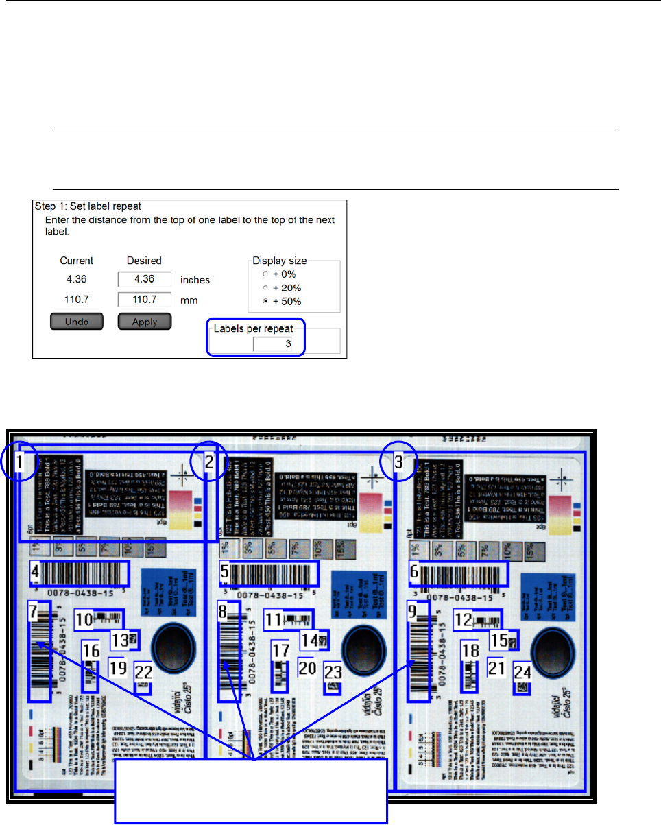
LVS-7510 Integrated System Operations Manual Version 20.2.X
LVS-7510 Integrated System Operations Manual Version 20.2.X Page 83 of 210
Use Global Copy to Add Sectors to All Labels Across the Screen:
1. Create a sector in the left-most lane.
2. Click the Global Copy button.
3. A new sector is created with matching parameters of the first sector.
Note: The LVS-7510 only creates the number of labels defined in the “Labels per repeat”
field on the “Step 1: Set label repeat” screen (see below).
Use Global Copy to Edit Sectors:
The example below displays three blemish sectors (1, 2 and 3). The Global copy feature allows you to make
the same change to all three sectors without making the changes to each sector individually,
If making a change to a sector in the first
label, the same sector in the other two
labels will automatically be updated.
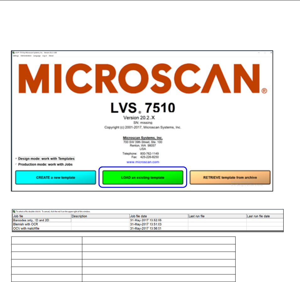
LVS-7510 Integrated System Operations Manual Version 20.2.X
LVS-7510 Integrated System Operations Manual Version 20.2.X Page 84 of 210
Design Mode: Load an Existing Template
1. To load an existing template, click the “Load an existing template” button on the Welcome screen.
2. A list of existing templates appears. Each column is described in the table below.
Column Description
Job file List of the job file names.
Description Description of each job file.
Job file date The date the job file was created.
Last run file Highest run number in the existing job.
Last run file date Last run file date for the job.
3. Choose the job you want by double-clicking the job name.
4. You can sort by any column by clicking on the column header.
5. The “Ready to Run” screen appears with the same job parameters that were originally set for that job.
For further instructions, see the section: “Design Mode: Ready to Run.”
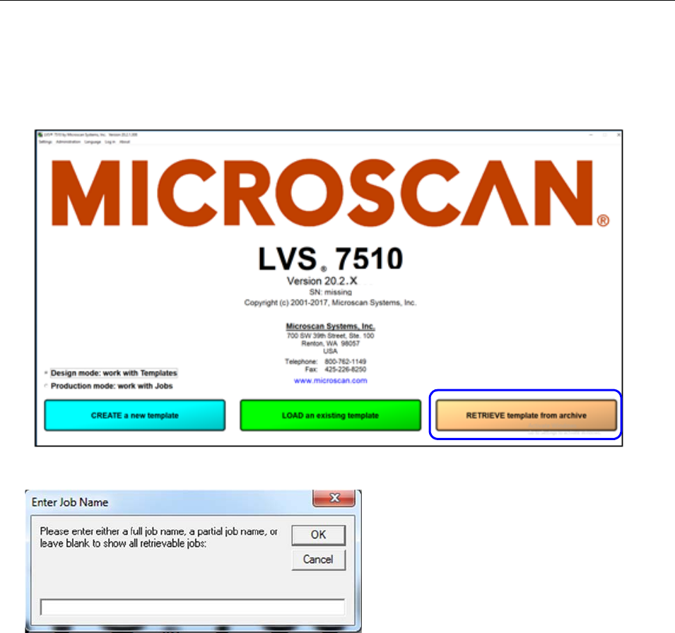
LVS-7510 Integrated System Operations Manual Version 20.2.X
LVS-7510 Integrated System Operations Manual Version 20.2.X Page 85 of 210
Design Mode: Retrieve a Template from Archive
1. To retrieve an archived template, click the “Retrieve template from Archive” button on the Welcome
screen. The “Enter Job Name” message box appears.
2. Enter the template name to retrieve or scan in a value.
Entry Methods:
o Scan a barcode containing the job name to retrieve the job.
o Enter the job name or part of the job name to filter jobs by the entered characters.
o If no entry is entered and the “OK” button is clicked, a list of archived templates appears.
Double-click the desired template.zip file. The file will unzip and open in the Ready to run state
(see section “Design Mode: Ready to Run” for more details).
If the template is already open and exists in the Design\Templates folder, a “Confirm Overwrite
Changes” warning message is displayed stating that this will overwrite changes made since last
retrieved.
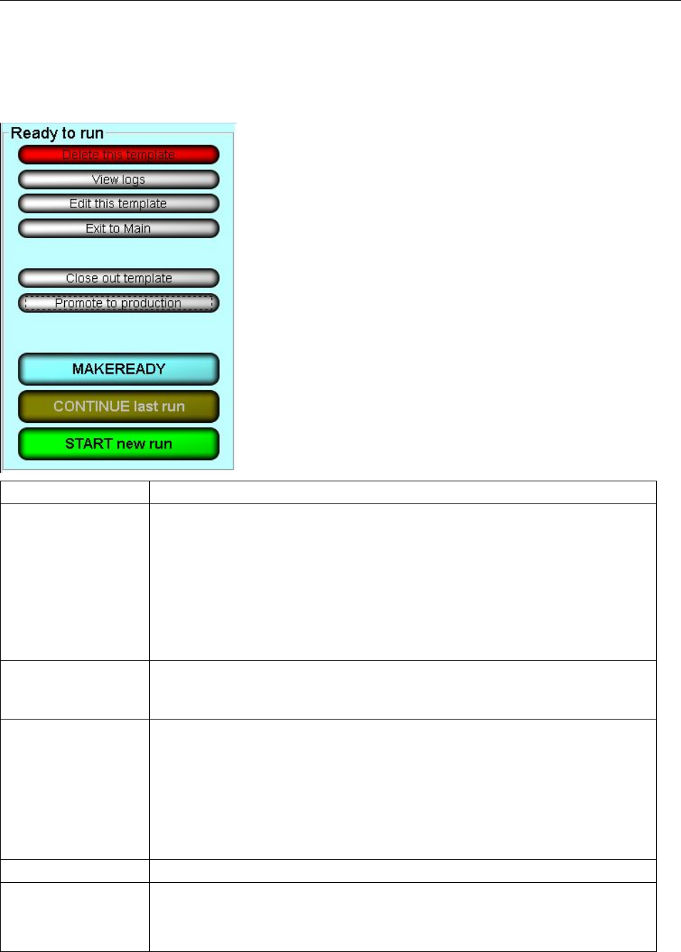
LVS-7510 Integrated System Operations Manual Version 20.2.X
LVS-7510 Integrated System Operations Manual Version 20.2.X Page 86 of 210
Design Mode: Ready to Run
Each button on the Design Mode “Ready to run” screen is described in the table below. In Design mode, the
“Ready to run” menu has a light blue (cyan) background.
Button Description
Delete this template Clicking the “Delete this template” button is used to remove the currently
loaded template from the Design environment. A warning message is
displayed to confirm the desired deletion. You are also prompted to delete the
template from the Design\Archive folder making the template no longer be
available from the “Retrieve template from archive” process (deleted forever).
Only operators who are granted the Allow Create NEW Job / Edit
permission are allowed to delete a template. For more information on
permissions, refer to: Welcome Screen Overview Administration
Operators Manage Operator Permissions within the LVS-7510 Software.
View Logs
A Report Log is created for every job. Click this button to view all previous
reports. For more information on reports, see:
Error Display Reports / QC File Viewer.
Edit this template
Clicking the “Edit this template” button will open the template editor and allow
the designer to make modifications to an existing template. Modifying the
template name will create a new copy of the existing template under a new
name.
Only operators who are granted the Allow Create NEW Job / Edit
permission is allowed to edit a job. For more information on permissions, refer
to: Welcome Screen Overview Administration Operators Manage
Operator Permissions within the LVS-7510 Software.
Exit to Main Click to return to the Welcome screen.
Close out template Click when changes to current template are completed. All files for the active
template will be zipped up and removed from the Design\Templates folder
and the zip file moved to the Design\Archive folder. All run data collected
during the design process is deleted prior to zipping and is not preserved.
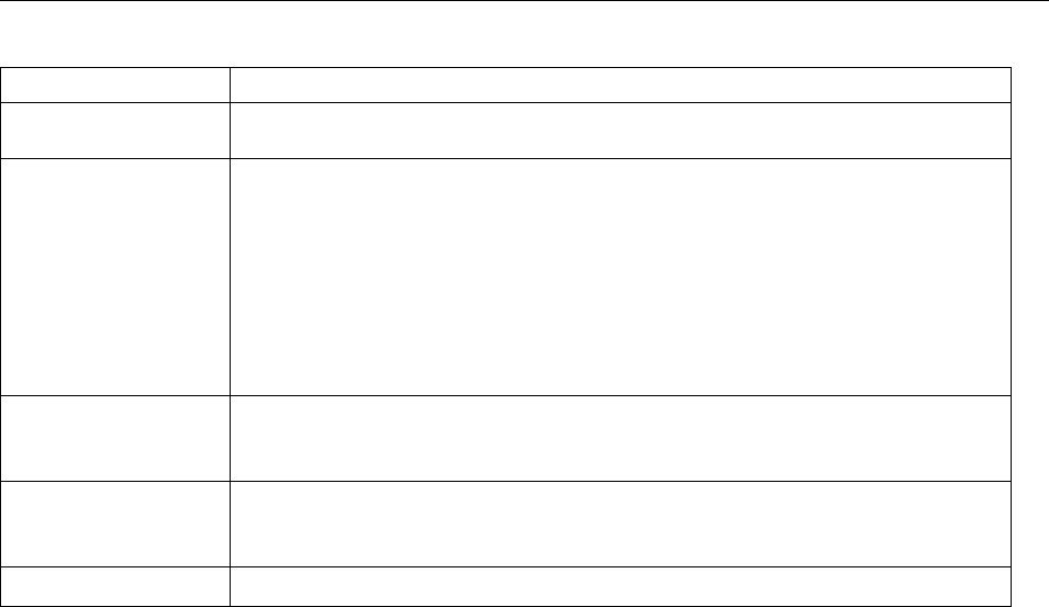
LVS-7510 Integrated System Operations Manual Version 20.2.X
LVS-7510 Integrated System Operations Manual Version 20.2.X Page 87 of 210
Button Description
After close out is complete, the template can be accessed by clicking the
“Retrieve template from archive” button on the Welcome screen.
Promote to
production Clicking the “Promote to production” button allows a template designer to
prepare a template for execution in the production environment. The designer
is prompted with the option to rename the template to a new job name to be
used in production. The designer is also be prompted to specify the location
of the match-to file if a match-to file was used in the template design and the
option was selected to assign a match-to file each time the template is
promoted. Job files are zipped and the new <jobname>.zip file is moved to
the Production\Import folder. If the job name exists in production, a warning
message is displayed.
Make Ready Make Ready operates exactly as if the system were running normally with the
exception that I/O signals to the stop motion/light tower are disabled. See the
section below titled “Make Ready Mode” for more information.
Continue Last Run Select this option if you desire to append to the most recent run’s CSV file.
You cannot continue a previous run after starting a new run. Only the current
run can continue.
Start New Run Click to begin a new run and new CSV file.
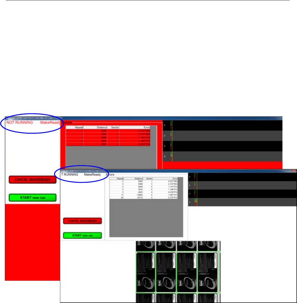
LVS-7510 Integrated System Operations Manual Version 20.2.X
LVS-7510 Integrated System Operations Manual Version 20.2.X Page 88 of 210
Make Ready Mode
Clicking the “MakeReady” button allows an operator to:
Simulate how inspections will perform
Simulate how the template created will work when the live job is run
Test any changes made
Test the system without triggering any output signals that might affect the thermal printer
After clicking the “MakeReady” button and when activated in the settings (ShowStatusAlert =1), the screen
flashes between red and white (see below) and the words “NOT RUNNING / Make Ready” scroll across the
top, left corner of the screen indicating the system is in MakeReady mode. Activating ShowStatusAlert
prevents accidental running in MakeReady mode by flashing red.
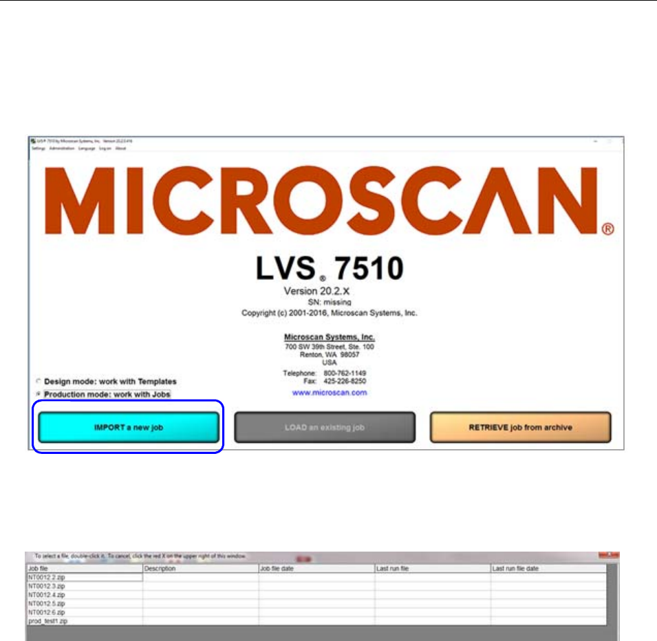
LVS-7510 Integrated System Operations Manual Version 20.2.X
LVS-7510 Integrated System Operations Manual Version 20.2.X Page 89 of 210
Production Mode: Import a New Job
1. To import a new job in Production mode, click the “IMPORT a new job” button on the Welcome screen.
Only one job can be loaded at a time. If an existing job is already loaded this button will be grayed out
and disabled.
2. An “Enter Job Name” message box appears. You can type the job name or partial name (to filter jobs) or
scan a barcode to input the job name or simply click “OK.”
3. A list of available jobs appears. Only the “Job file” column value is populated because the information for
the other columns is not available until the job is unzipped. Choose the job you want by double-clicking
the job name.
4. The “Ready to Run” screen appears with the same job parameters that were originally set for that job.
For further instructions, see the section: “Production Mode: Ready to Run.”
LVS-7510 Integrated System Operations Manual Version 20.2.X
LVS-7510 Integrated System Operations Manual Version 20.2.X Page 90 of 210
AutoExecute Functionality
LVS-7510 monitors the contents of a specified folder and, when a zipped LVS job is copied to that file
location, the LVS-7510 automatically imports the job and loads it. The system also offers the option of
immediately running the job once it is loaded or allowing the operator to start the job. This functionality is
available only in Production mode.
Configuration
The user must specify the folder that will be monitored by the LVS-7510 by setting a CFG (configuration) file
specifying the path of the folder on the PC. The user is also required to activate AutoExecute via a
configuration setting change. Optionally, the user can configure the system to determine whether or not the
LVS-7510 will automatically start the job once imported or await input from the operator. Below is a table
outlining the CFG file settings for AutoExecute functionality.
[AutoExecute] CFG
config settings Setting Format Functionality
AutoExecuteStatus On or Off Reports the current runtime status of the
AutoExecute functionality.
Path String Specifies the folder location that will be
monitored
StartRunOnceImported On or Off Determines if the job will be
automatically started once it is imported
UseAutoExecute On or Off Activates the AutoExecute functionality
Run Time Functionality
Once the CFG is set to use AutoExecute, the software runs in production mode and will monitor the contents
of the specified folder, which, henceforth, is referred to as the “AutoExecute folder”. Once a zipped job is
copied to the AutoExecute folder, LVS-7510 automatically unzips and imports the job, stores it in the
Production Jobs folder, loads the job and deletes the zip file from the AutoExecute folder.
If the setup has StartRunOnceImported activated, then LVS-7510 automatically starts a new run; otherwise,
LVS-7510 remains on the ready screen until the operator starts the new run manually. The operator does not
have the ability to manually load or import a job while AutoExecute mode is active. These buttons are
grayed-out.
There is an option on the Welcome screen to activate and deactivate the AutoExecute mode via a radio
button. There is also a radio button that allows LVS-7510 to be switched from automatically running upon job
import, to await instructions from the operator after the job is loaded and ready to run.
Operating Considerations
It is recommended that the AutoExecute folder be populated one job at a time and that the previous job be
fully completed and closed out prior to another job being copied to the AutoExecute folder. This is to
minimize any mistakes in the production process flow so that the correct labels are printed for the job loaded.
If multiple jobs are added to the AutoExecute folder in quick succession, AutoExecute functionality imports
the jobs on a first-in-first-out basis. Once the first job copied to the AutoExecute folder is closed out, the job
that was copied into the AutoExecute folder second is imported. The jobs queued to the printer are sent in
the same order as the LVS jobs that are stored in the AutoExecute folder.
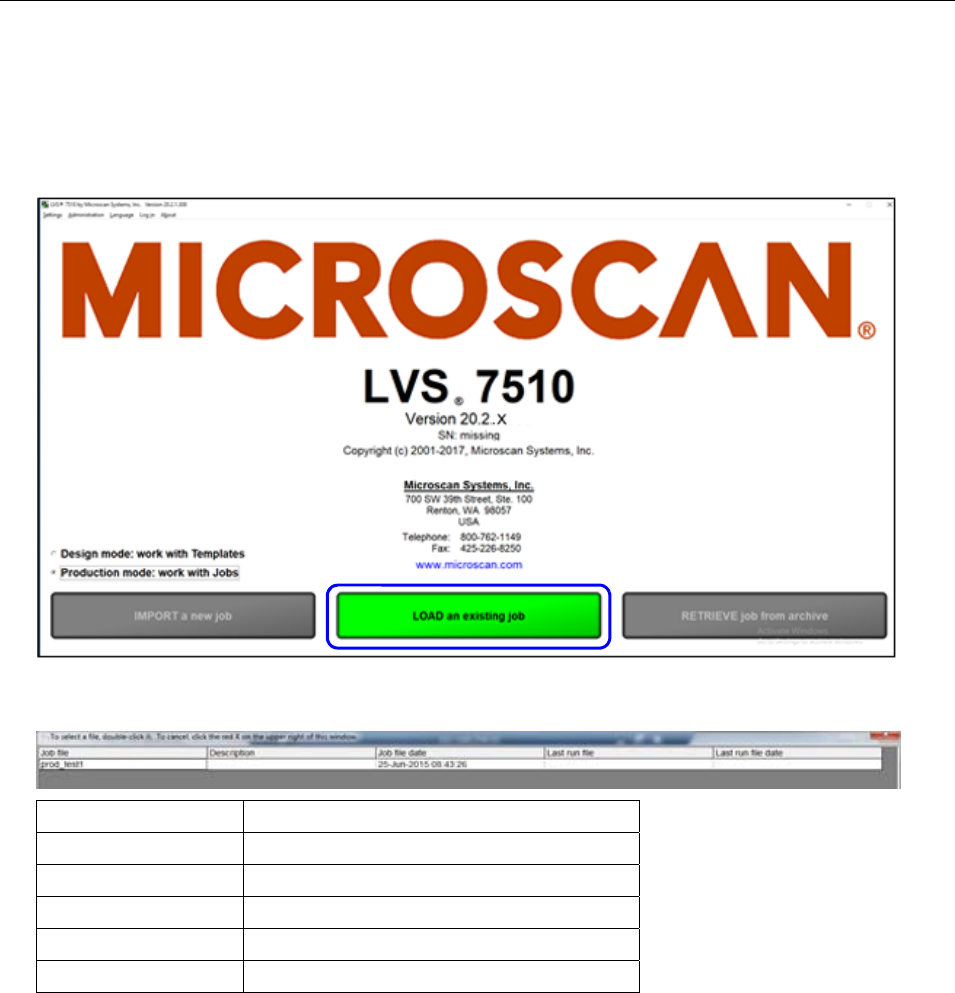
LVS-7510 Integrated System Operations Manual Version 20.2.X
LVS-7510 Integrated System Operations Manual Version 20.2.X Page 91 of 210
Production Mode: Load an Existing Job
1. To load an existing job, click the “LOAD an existing job” button on the Welcome screen. In Production
mode, only one active job is allowed. If there is no active job loaded, then the “LOAD an existing job
button” is grayed out and disabled.
2. A list view opens showing the currently active job available for selection. Each column is described in the
table below. In Production mode, only one active job is allowed so there will always be one job in the list.
Column Description
Job file List of the job file names.
Description Description of each job file.
Job file date The date the job file was created.
Last run file Highest run number in the existing job.
Last run file date Last run file date for the job.
3. Choose the job by double-clicking the job name.
4. The “Ready to Run” screen appears with the same job parameters that were originally set for that job.
For further instructions, see the next section: “Production Mode: Ready to Run.”
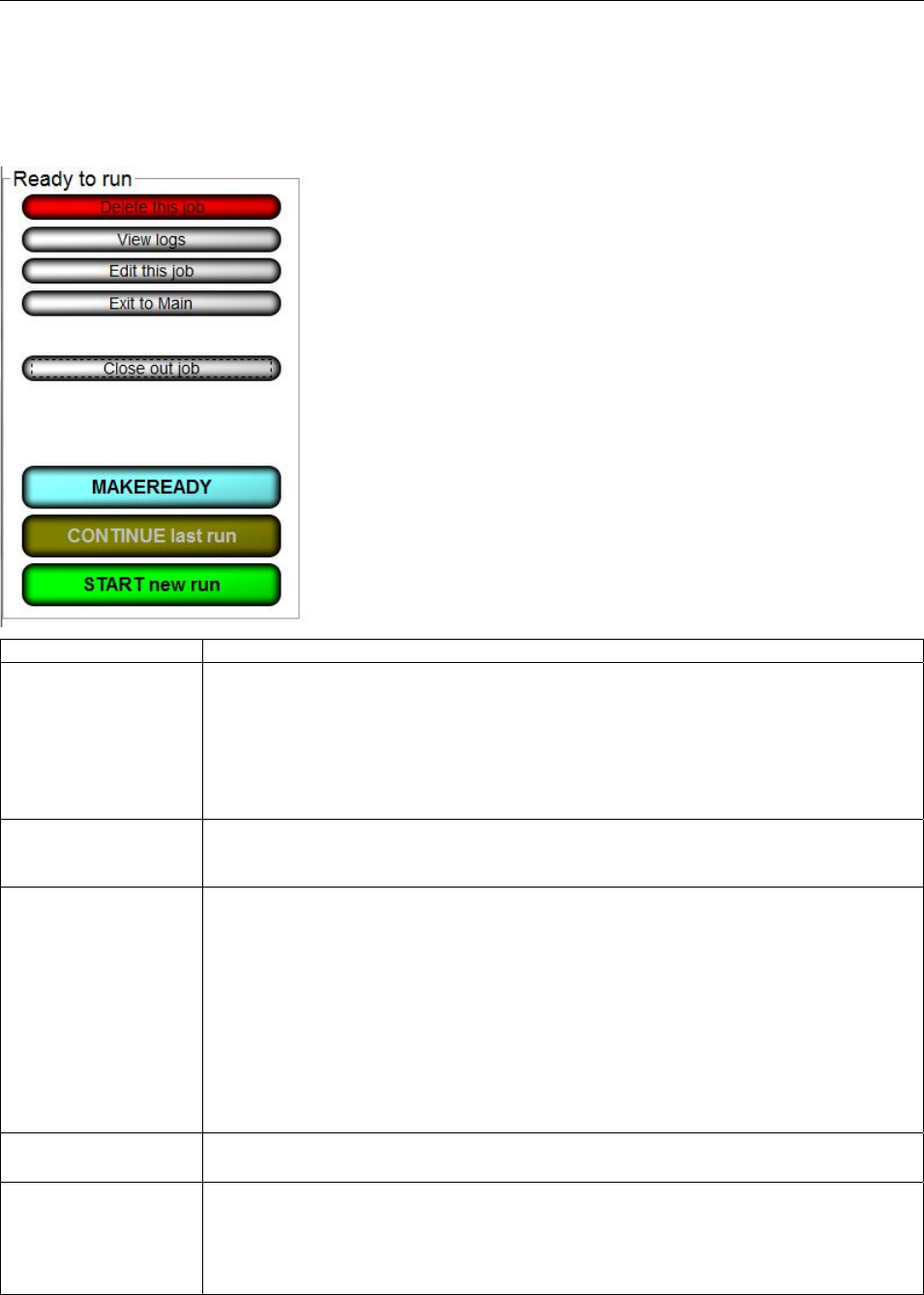
LVS-7510 Integrated System Operations Manual Version 20.2.X
LVS-7510 Integrated System Operations Manual Version 20.2.X Page 92 of 210
Production Mode: Ready to Run
Each button on the Production Mode “Ready to run” screen is described in the table below. In Production
mode, the “Ready to run” menu has a white background.
Button Description
Delete this job Clicking the “Delete this job” button is used to remove the currently loaded job
from the Production environment. A warning message is displayed to confirm the
desired deletion. You are also prompted to permanently delete the job from the
Production\Archive folder. Only operators who are granted the Allow Create
NEW Job / Edit permission are allowed to delete a job. For more information on
permissions, refer to: Welcome Screen Overview Administration
Operators Manage Operator Permissions within the LVS-7510 Software.
View Logs
A Report Log is created for every job. Click this button to view all previous
reports. For more information on reports, see:
Error Display Reports / QC File Viewer.
Edit this job
Click to change the current job settings. Clicking this button opens the job editor
and allows the operator to make modifications to the existing job. Only operators
who are granted the Allow Create NEW Job / Edit permission are allowed to edit
a job. NOTE: Editing a production job does NOT edit the Design Template.
Changes in Production Mode should be avoided as they only affect the current
job and revision control may be harder to control. Operators with this permission
are allowed to change job settings but modifying the job name is not allowed in
Production mode. If the operator does not have the Allow Create NEW Job /
Edit permission, a “Not Authorized” message appears. For more information on
permissions, refer to: Welcome Screen Overview Administration
Operators Manage Operator Permissions within the LVS-7510 Software.
Exit to Main
Click to change to a previously set up job. Clicking this button will take you back
to the Welcome Screen where you may select other Production mode options.
Close out job Click when the job is completed and/or a new or archived job needs to be loaded.
All files in the active <jobname> folder are zipped to <jobname>.zip and moved to
the Production\Archive folder. All run data collected during the job execution is
stored in <jobname>.zip. The close out process creates a report file that is
located in the Production\Output folder.
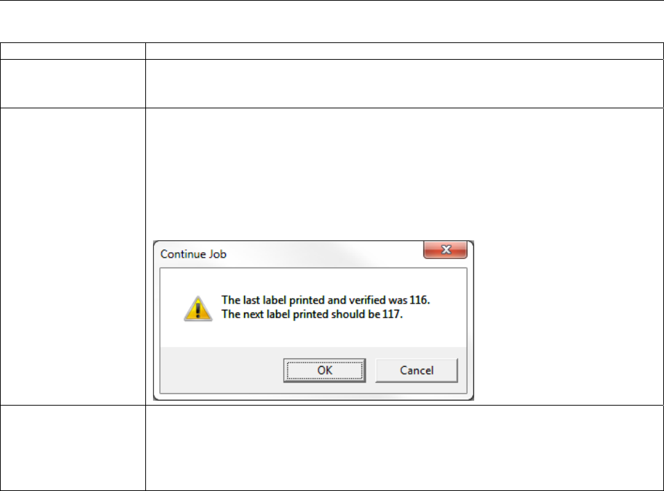
LVS-7510 Integrated System Operations Manual Version 20.2.X
LVS-7510 Integrated System Operations Manual Version 20.2.X Page 93 of 210
Button Description
Make Ready Make Ready operates exactly as if the system were running normally with the
exception that no data is stored and no I/O is triggered. See the section below
titled “Make Ready Mode” for more information.
Continue Last Run Clicking this button will allow the active job to be continued beginning after the
last evaluated label. If the template or job is using a match-to file, the number of
labels in a complete job is known. The “Continue Job” message (see below) is
displayed with the number of the next label to be printed. Click “OK” to open
Running mode. The LVS-7510 will wait on the printer to start printing the next
label to be validated. The validation results will be appended to the previous
Report/Audit Log file. Refer to the “Design and Production Mode: Running”
section for further details.
Start New Run Click to begin a new run and new CSV file. Clicking this button will begin a new
run log for the current job. If the job has a match-to file, then the operator is
prompted to select a new match-to file. The system will be put into Running
mode, where the LVS-7510 is waiting for the printer to begin printing labels. Refer
to the “Design and Production Mode: Running” section for further details.
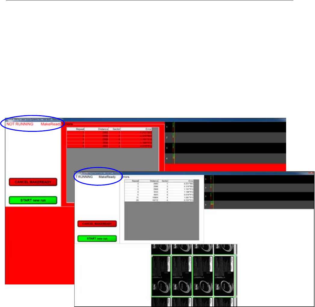
LVS-7510 Integrated System Operations Manual Version 20.2.X
LVS-7510 Integrated System Operations Manual Version 20.2.X Page 94 of 210
Make Ready Mode
Clicking the “MakeReady” button allows an operator to:
Simulate how inspections will perform
Simulate how the template created will work when the live job is run
Test any changes made
Test the system without triggering any output signals that might affect the thermal printer
After clicking the “MakeReady” button and when activated in the settings (ShowStatusAlert =1), the screen
flashes between red and white (see below) and the words “NOT RUNNING / Make Ready” scroll across the
top, left corner of the screen indicating the system is in MakeReady mode. Activating ShowStatusAlert
prevents accidental running in MakeReady mode by flashing red.
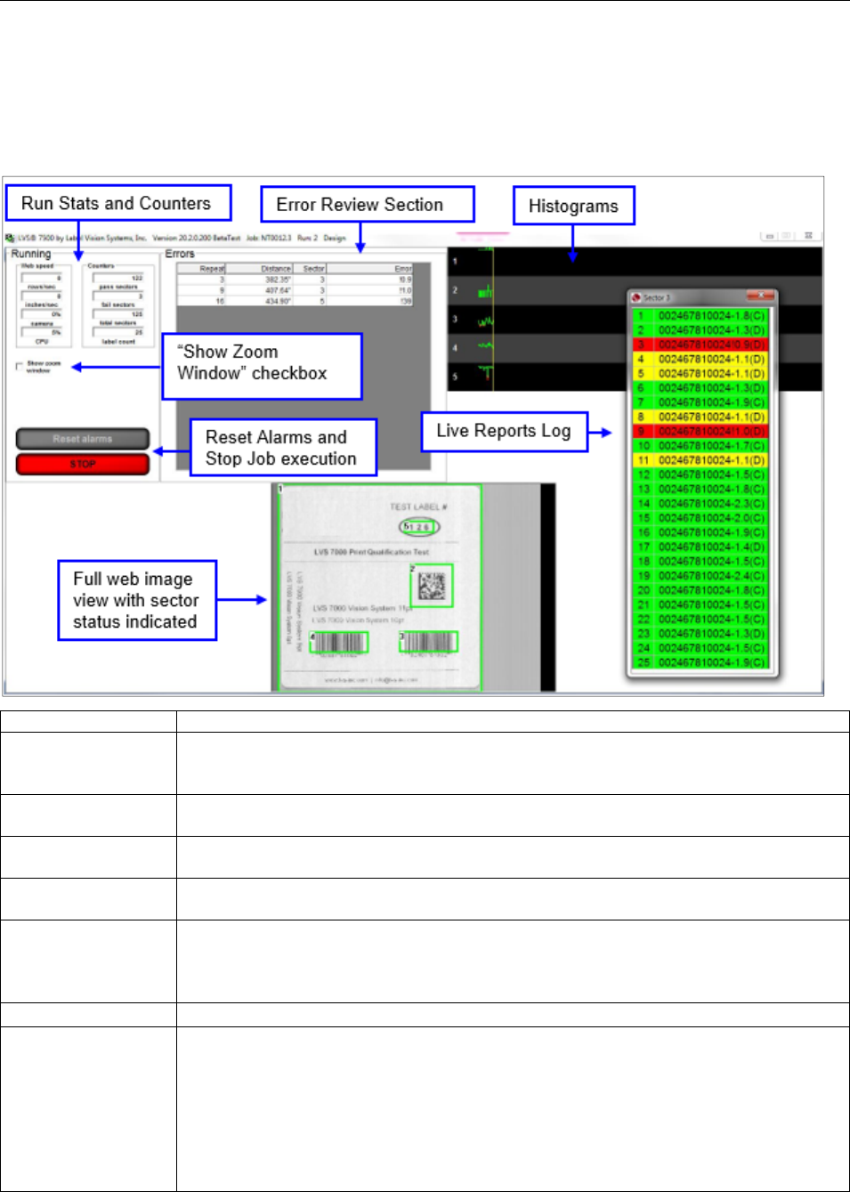
LVS-7510 Integrated System Operations Manual Version 20.2.X
LVS-7510 Integrated System Operations Manual Version 20.2.X Page 95 of 210
Design and Production Mode: Running
The Design and Production mode Running functionality (running the job) are the same for Design and
Production modes. The Running screen is typically what you monitor at all times in a production
environment. The features on this screen are described in the table below:
Field Description
Web Speed This gives the operator how many rows per second are being analyzed, as well as
how many inches per second the printer is traveling. This calculation is based
upon the Label Repeat data entered in Step 1.
Counters There are two conditions being counted: All “passed” sectors and all “failed”
sectors. These two conditions are totaled at the bottom of this column.
Camera Shows a percentage of the Camera Speed. A warning message will appear and
Stop Motion trigger if the speed is too high.
CPU Shows the CPU Usage. A warning message appears if the CPU usage is too high.
CPU overrun can cause Not Assessed !NA errors.
Reset Alarms On the Alarm matrix, there is a “hold” function if/when an error occurs; this is
indicated by the term “Hold” appearing in the “Dwell” column on the Alarm matrix.
The Reset Alarms button releases the error condition and is visible only when the
“Hold” function is activated in the Alarm matrix.
Stop Press the Stop button to stop the inspection.
Error Display This is a very helpful feature for the operator to analyze only the errors as they
happen. Or, the operator may choose to study one error condition at a time. This
feature is activated by clicking on the error. This causes the software to show an
image of the error as superimposed thumbnail images (Blemish). The process of
showing this error image can be performed while the system is in the Running
condition. A series of error images are stored in the log file of each job.
Thumbnails of the actual errors can be viewed “offline”. See the Error Display
section below for more information.
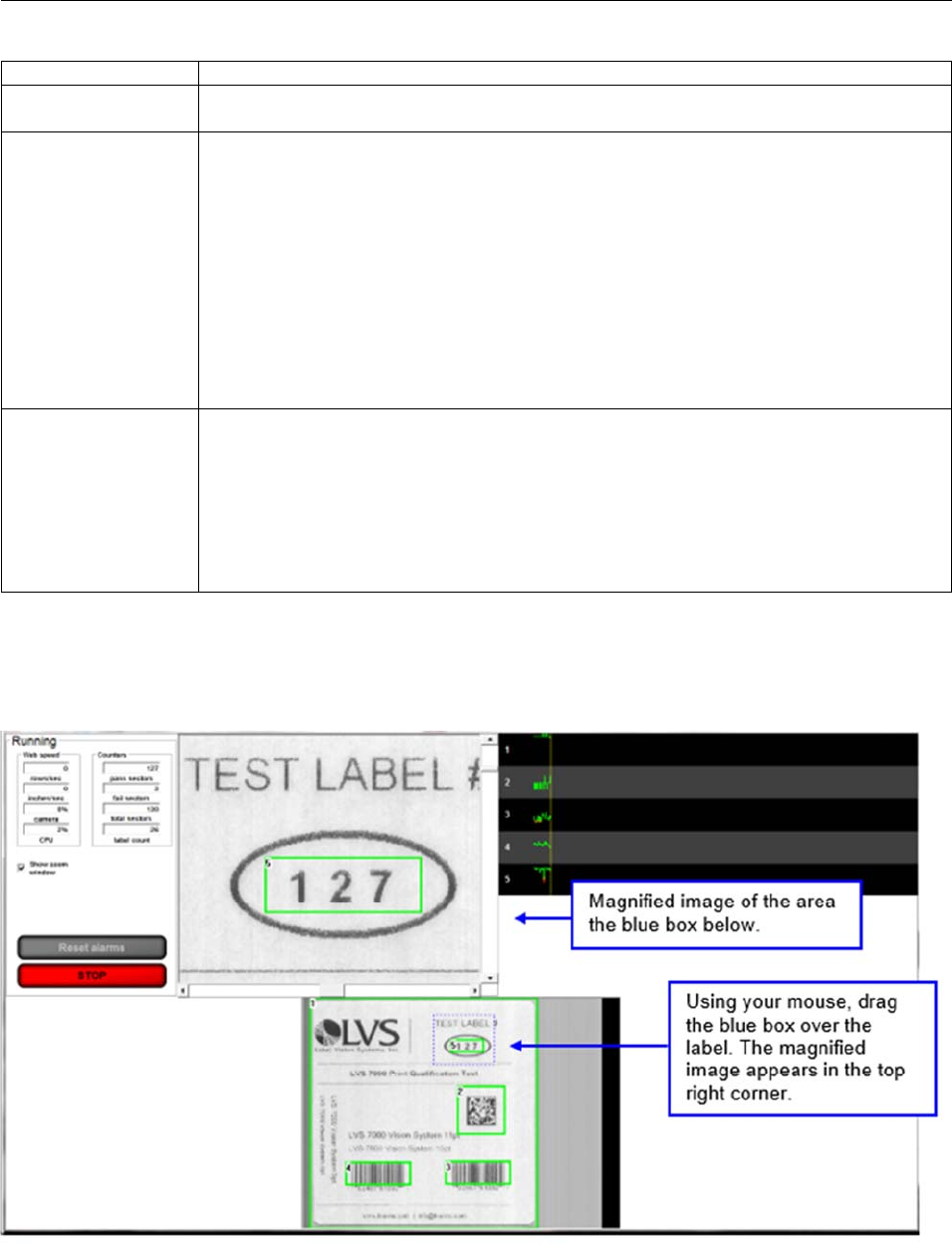
LVS-7510 Integrated System Operations Manual Version 20.2.X
LVS-7510 Integrated System Operations Manual Version 20.2.X Page 96 of 210
Field Description
Full Web Image The image at the bottom of the Running Screen is the entire field of view and will
update up to 10 images per second as the printer is running.
Live Reports Log A log will appear overlaid onto the Running Screen when the operator clicks inside
a sector or on the sector number in the histogram. This log represents what the
software sees inside this sector.
A green box indicates a good read.
A red box indicates an error condition has occurred.
A yellow box indicates a good read below the warning threshold.
This log can be moved to any position on the Running Screen by left click and hold
at the very top of the log screen. To get a freeze frame of this box click on any
other non-sector part of the full web image. This will cause the box to stop
updating. To resume the update, just click in the desired sector. Close by clicking
the red X (Close) box in the top right corner.
Histograms At the top of the Running Screen is a section for displaying a histogram for every
error condition the software is trained to analyze. It is color coded.
Green is “good’
Red is “bad”
Yellow is “good” but below the warning threshold
Each sector “Type” will have its own graph. All sectors of a given type will be
displayed within the graph designated for that “Type”.
Show Zoom Window
Check the “Show Zoom Window” box to view a magnified image of the label. After checking this box, a blue
box appears in the full web image view. Use your mouse to move the blue box over any portion of the label,
and then a magnified image appears in the top right corner of the screen (see below).
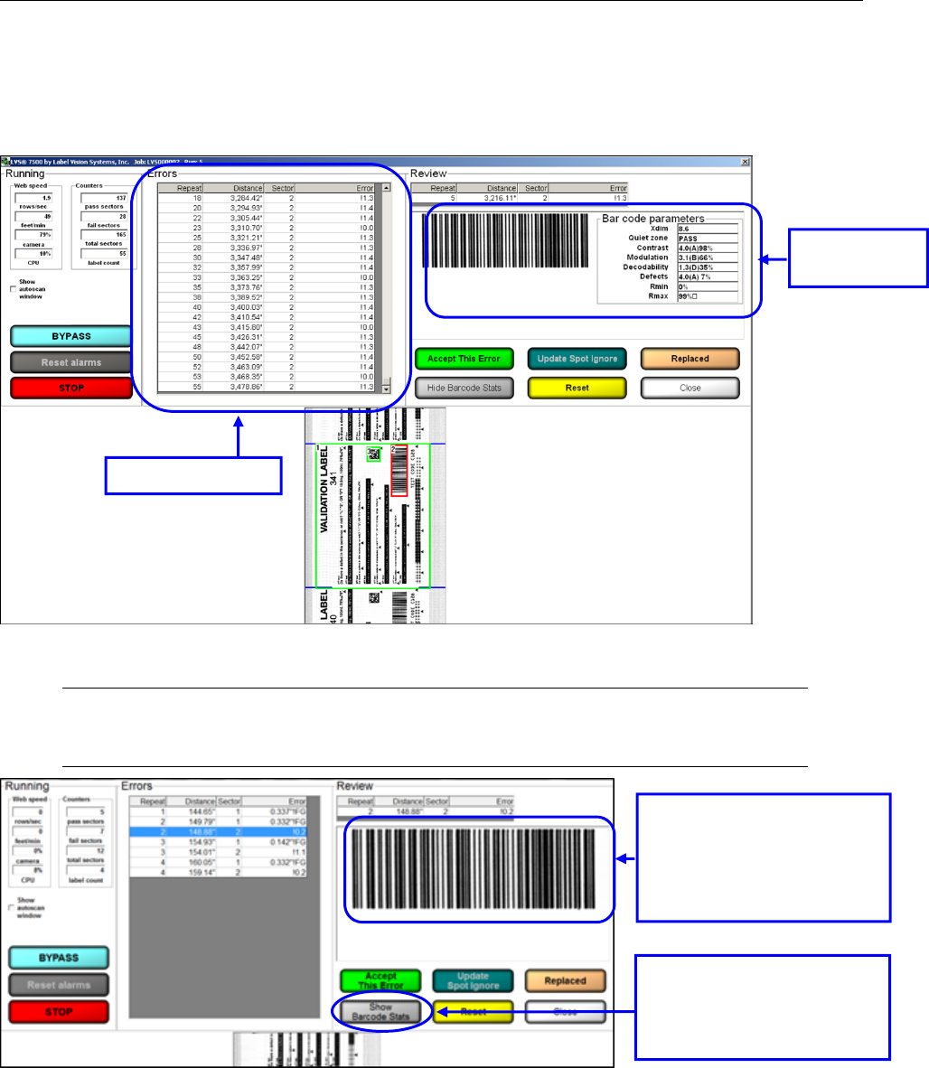
LVS-7510 Integrated System Operations Manual Version 20.2.X
LVS-7510 Integrated System Operations Manual Version 20.2.X Page 97 of 210
Error Display
The Error Display log can be accessed on the Running screen while you are running the job or after you stop
the job. Click on an error to view the barcode image and barcode parameters.
To hide the barcode parameters, click the “Hide Barcode Stats” button; this removes the barcode parameters
from the screen and enlarges the barcode image.
Note: After clicking the “Hide Barcode Stats” button, the name changes to “Show Barcode
Stats.” Click this button to display the barcode parameters on the screen.
Error Display Log
Barcode
parameters
After clicking the “Hide
Barcode Stats” button, the
barcode parameters are
hidden and the barcode
image is enlarged.
Click the “Show Barcode
Stats” button to display the
barcode parameters on the
screen.
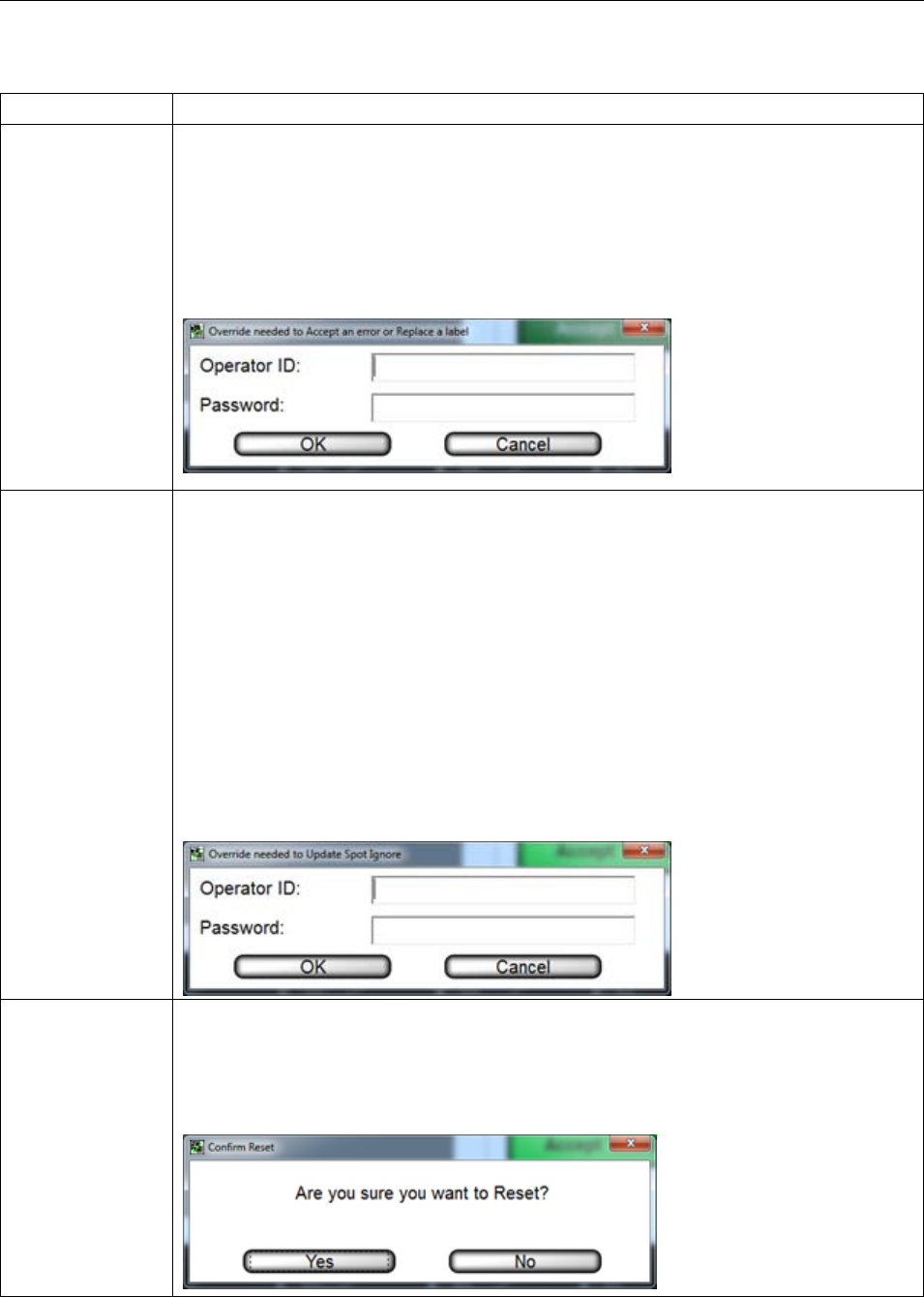
LVS-7510 Integrated System Operations Manual Version 20.2.X
LVS-7510 Integrated System Operations Manual Version 20.2.X Page 98 of 210
Additional error display options include:
Button Description
Accept This Error Click this button to approve the error; the error is marked as OK in the error log file
and removed from the errors list. The button is active when the job is in run mode.
Only operators granted the Allow Accept / Replace Errors permission are allowed
to accept the error. The following message appears for operators without permission
to accept the error (see screenshot below). An authorized Operator ID and Password
must be entered or the operator will not be allowed to approve the error. For more
information on permissions, refer to: Welcome Screen Overview Administration
Operators Manage Operator Permissions within the LVS-7510 software.
Update Spot
Ignore
Draws an ignore box around the error so that it will not appear again and every
instance of the error will be removed from the errors list. The log file will also show an
OK for every instance of this error.
The ignore area is yellow if you edit the blemish sector.
In the “Settings” menu, when RelearnAuthorization=0, any operator granted the
“Allow Accept/Replace Errors” permission can use this feature.
When RelearnAuthorization=1, the operator must have “Allow Administration” rights
to use this feature.
The following message appears for operators without permission to use the “Update
Spot Ignore” feature (see screenshot below). An administrator’s Operator ID and
Password must be entered or the operator will not be allowed to ignore the areas.
For more information on permissions, refer to: Welcome Screen Overview
Administration Operators Manage Operator Permissions within the LVS-7510
software.
Reset Places previously accepted and replaced errors back into the errors list and restores
their original error codes in the log file. This feature also removes all spot ignore
updates. The button is active when the job is in run mode.
After clicking the “Reset” button, the following message appears. Click Yes to reset
or No to cancel.
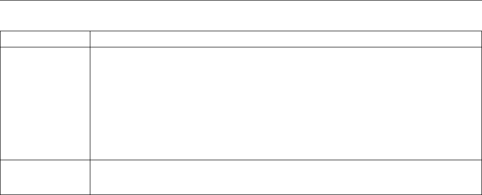
LVS-7510 Integrated System Operations Manual Version 20.2.X
LVS-7510 Integrated System Operations Manual Version 20.2.X Page 99 of 210
Button Description
Hide Barcode
Stats
Click this button to hide the barcode parameters on the screen and enlarge the
barcode image.
After clicking this button, the button name changes to “Show Barcode Stats.” Click
this button for the barcode parameters to appear on the screen.
The settings for this button are controlled in the “Settings” menu > [System] section >
ShowRuntimeGradeStats.
ShowRuntimeGradeStats=0 (default) – Disables the “Hide Barcode Stats” button.
ShowRuntimeGradeStats=1 – Enables the “Hide Barcode Stats” button.
Close Click the “Close” button to close the error display window and return to the “Running
the Job” screen.
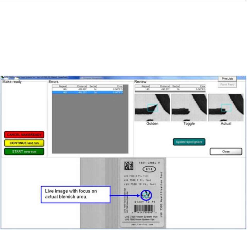
LVS-7510 Integrated System Operations Manual Version 20.2.X
LVS-7510 Integrated System Operations Manual Version 20.2.X Page 100 of 210
Blemish Error Display
When viewing a blemish error, three views are available on the screen:
Golden – Displays the golden image
Toggle – Toggles between the golden image and actual image
Actual – Displays the actual blemish image
Only a single image of the error is displayed when viewing other types of errors. For example, a No Read
error on a barcode would only show an image of the barcode so that you can examine the problem.
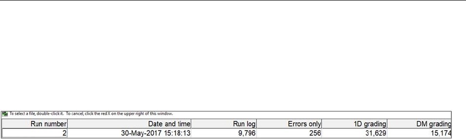
LVS-7510 Integrated System Operations Manual Version 20.2.X
LVS-7510 Integrated System Operations Manual Version 20.2.X Page 101 of 210
Reports / QC File Viewer
The Reports Screen is used to view the report logs created for each job.
Each line of data starts with the run number followed by a date/time stamp, decoded string, error code (if
any), and other data associated with the image being inspected. For a full list of error codes, see: Step 6:
Alarm Matrix Error Code Definitions on page 76.
The report type is displayed in the column header (such as Errors only, 1D grade details, etc.). To view a
particular report, click on the desired run located under the corresponding header.
The “Run log” column allows you to view data for all sectors for that particular run. All ANSI/ISO parameters
are reported under 1D, 2D grade details.
The data is stored in a .csv (comma separated values) format. This format is a text file where fields are
delimited by commas and records are delimited by a <CR><LF> pair. By default these files are stored in the
following directories:
For installations of software version 20.2.X on Windows® 7 Professional and Windows® 8.1
Professional operating systems: C:\LvsData\LVS 7500\Production\Jobs
Jobs created in earlier versions of the software are not supported. Manually backup any desired data
and manually delete the C:\Users\[User Login Name]\AppData\Roaming\Label Vision Systems\LVS
7500. Then, install software release 20.2.X as a new installation.
The operator may choose to print a report for an entire run or print a report of errors only.
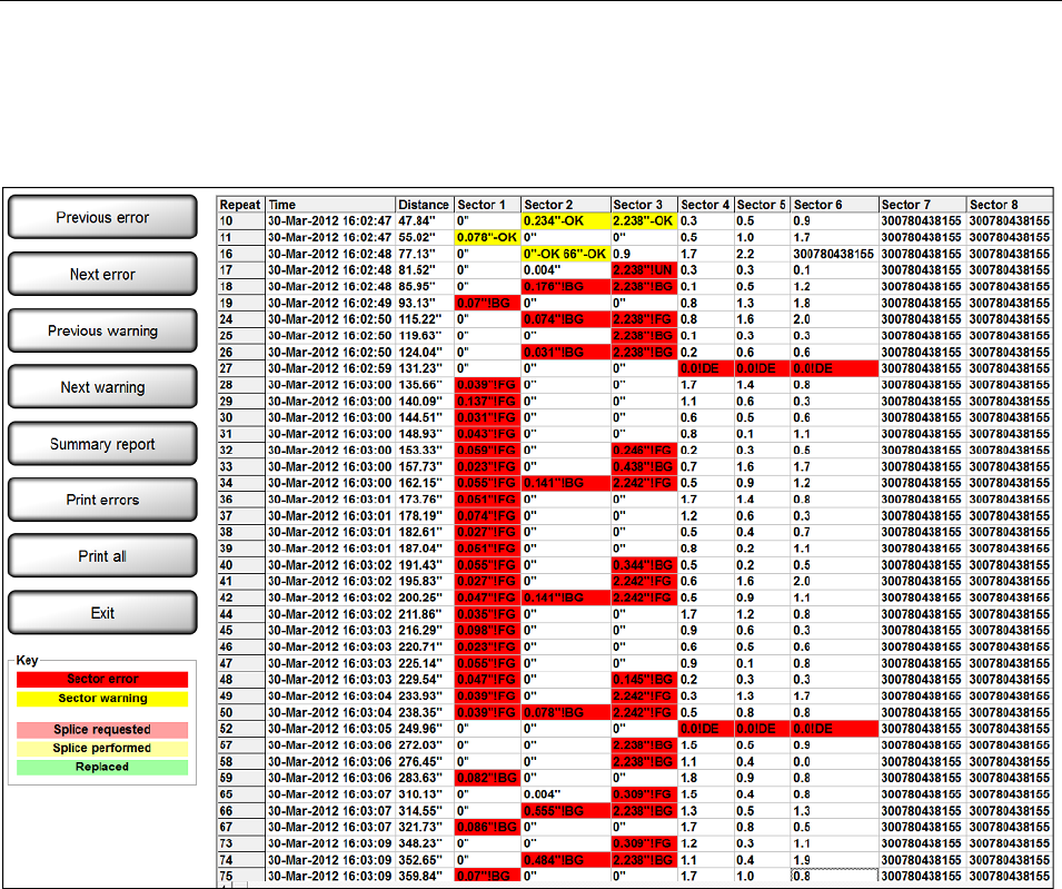
LVS-7510 Integrated System Operations Manual Version 20.2.X
LVS-7510 Integrated System Operations Manual Version 20.2.X Page 102 of 210
Sample Reports
Errors Only Report
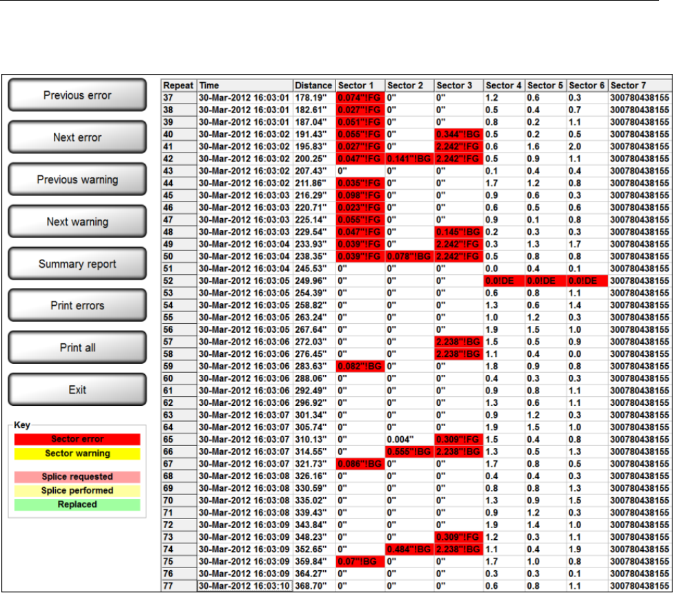
LVS-7510 Integrated System Operations Manual Version 20.2.X
LVS-7510 Integrated System Operations Manual Version 20.2.X Page 103 of 210
Run Log
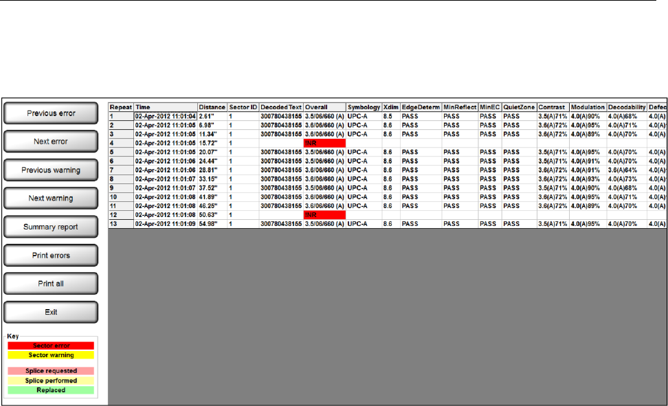
LVS-7510 Integrated System Operations Manual Version 20.2.X
LVS-7510 Integrated System Operations Manual Version 20.2.X Page 104 of 210
1D Grade Details
View 1D grade details by double-clicking on a job in the 1D grading column.
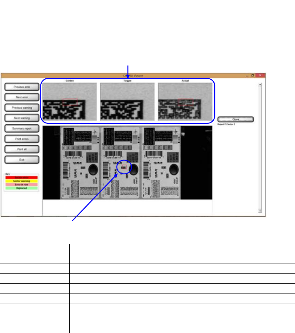
LVS-7510 Integrated System Operations Manual Version 20.2.X
LVS-7510 Integrated System Operations Manual Version 20.2.X Page 105 of 210
Run Log with Images
Blemish, barcode, and OCR/OCV error images can be viewed by double clicking on the red blemish cell in
the log file. An error display screen will then appear. If the error is a blemish, the Golden Image will show on
the Left; a Toggle between Golden and Actual in the center; and the Actual Blemish image is on the right.
Button Definitions:
Button Description
Previous Error Moves upward from the current file location to the next error.
Next Error Moves downward from the current file location to the next error.
Previous Warning Moves upward from the current file location to the next warning.
Next Warning Moves downward from the current file location to the next warning.
Summary Report Click to view the Summary Report.
Print errors Click to print the errors only.
Print All Click to print all information for the run.
Exit Click to close the QC File Viewer and return to the LVS-7510.
Toggle screens of Golden as compared to the actual.
Blemish location on label
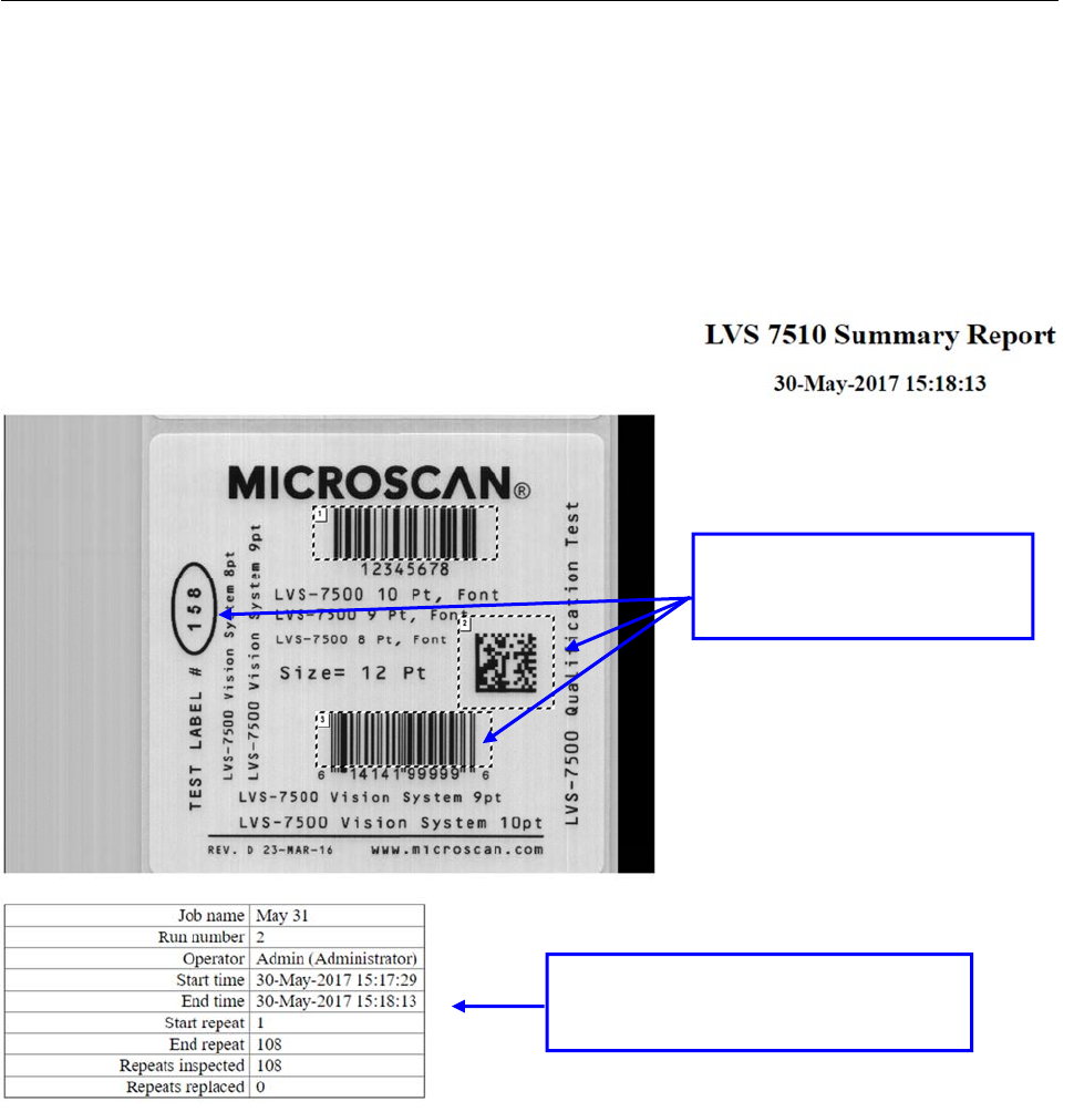
LVS-7510 Integrated System Operations Manual Version 20.2.X
LVS-7510 Integrated System Operations Manual Version 20.2.X Page 106 of 210
Summary Report
The LVS-7510 Summary Report can be accessed by clicking on the “Summary Report” button when viewing
a log file. The LVS-7510 Summary Report gives a summation of the entire job and each sector’s settings and
parameters. The report also shows example images where sectors were drawn. See a sample LVS-7510
Summary Report below.
The LVS-7510 Summary Report appears when configured for HMTL only in Internet Explorer, Firefox or
Chrome web browsers; no other web browser is supported. Alternately, the Summary Report can be
configured to create a .pdf report.
A detailed analysis of each
sector is displayed in the
following report sections.
Displays the job name, operator, and
date and time when the job began and
ended.
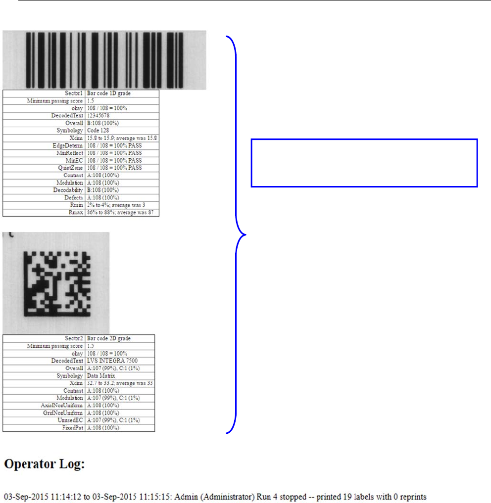
LVS-7510 Integrated System Operations Manual Version 20.2.X
LVS-7510 Integrated System Operations Manual Version 20.2.X Page 107 of 210
Detailed analysis is provided for each sector on
the label. This example shows the barcode
grade sector and summary results.
LVS-7510 Integrated System Operations Manual Version 20.2.X
LVS-7510 Integrated System Operations Manual Version 20.2.X Page 108 of 210
Preventive Maintenance
Sensor Instructions
Weekly cleaning of the sensor is recommended to maintain optimum performance. To maintain a clean and
clear appearance, spray a soft, lint-free, non-abrasive towel or cloth with a commercially available household
glass cleaner, such as Windex®, Glassex®, VISS®, and Mr. Muscle® and gently clean the outside of the
sensor glass.
DO NOT directly spray the sensor glass with glass cleaner; always spray a towel or cloth with glass
cleaner and then gently wipe the sensor glass.
DO NOT use an industrial-strength glass cleaner.
Calibration Card Instructions
Replace the Calibrated Conformance Standard Test Card every two years.
If you have any questions or concerns about the performance of the LVS-7510, please call Omron Microscan
or your Omron Microscan distributor.
Troubleshooting
Problem Description Possible Causes
System will not acquire images The readhead has lost power.
The readhead to LVS-7510 interface cables are not
plugged in or are damaged.
System is acquiring every other label The label repeat is set too large.
Image has uneven lighting An LED may have burned out in the sensor.
The sensor may have a label stuck to it
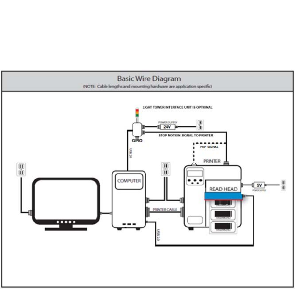
LVS-7510 Integrated System Operations Manual Version 20.2.X
LVS-7510 Integrated System Operations Manual Version 20.2.X Page 109 of 210
Mechanical Diagrams
All technical drawings are copyrighted in respect to their manufacturer. All respected trademark rights are
reserved.
LVS-7510 Basic Wire Diagram
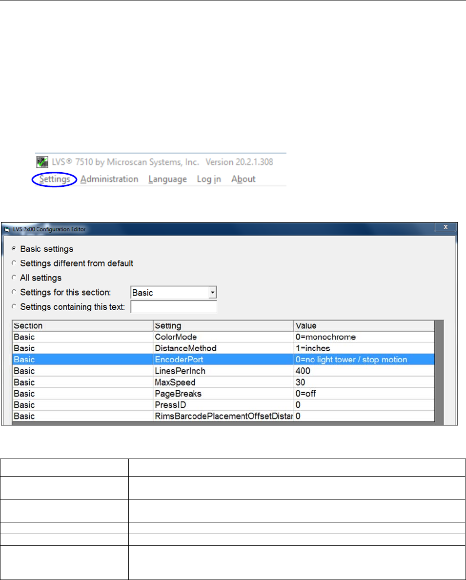
LVS-7510 Integrated System Operations Manual Version 20.2.X
LVS-7510 Integrated System Operations Manual Version 20.2.X Page 110 of 210
Appendix A: User Configurable Settings
Settings Configuration Editor
The LVS-7510 software is configurable through options that are user configurable. The “Settings” menu bar
feature opens the LVS-7510 Configuration Editor which allows you to configure the basic and advanced
features and functionality of the LVS-7510. A user must be assigned administrator rights to access the
“Settings” menu bar. Refer to the “List of User Configurable Settings” section below for a description of the
available settings and options.
The LVS-7510 Configuration Editor offers the following options:
Option Description
Basic settings Select this option to display the settings considered to be basic to LVS-
7510 configuration.
Settings different from
default Select this option to display any values that have been modified to a value
other than the default value.
All settings Select this option to display all settings listed alphabetically by “Section.”
Settings for this section Click the drop-down box to display all settings for the selected section.
Settings containing this
text Enter a text string to search for settings containing the entered text. For
example, typing “camera” in the text field will display all settings containing
the word “camera.”
Each setting is grouped by “Section,” “Setting,” and “Value” (see screenshot below).
Double-click a setting row. The “LVS-7510 Configuration Editor Individual Setting” window appears providing
the Section, Setting, Default, Value, and Setting Description.
The only editable field is the “Value” field. All other fields cannot be edited.
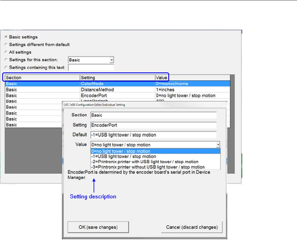
LVS-7510 Integrated System Operations Manual Version 20.2.X
LVS-7510 Integrated System Operations Manual Version 20.2.X Page 111 of 210
Click “OK (save changes)” to save your changes or “Cancel (discard changes)” to discard any changes.

LVS-7510 Integrated System Operations Manual Version 20.2.X
LVS-7510 Integrated System Operations Manual Version 20.2.X Page 112 of 210
List of User Configurable Settings
Active Directory
Setting: ActiveDirectoryAuthentication
Options: 0=off
1=ON
Default: 0=off
When ActiveDirectoryAuthentication is enabled
the LVS-7510 software will attempt to use
Microsoft Server Active Directory for User
Administration.
Setting: ActiveDirectoryDomain
Options: Text string
Default: None
Microsoft Server Active Directory Domain
name. Example: your-company.com.
Setting: ActiveDirectoryLVSAllowAbort
Options: Text string
Default: None
When ActiveDirectoryAuthentication is enabled,
this is the Active Directory group that gives
LVS-7510 users the Allow Abort permission.
Setting: ActiveDirectoryLVSAllowAcceptReplace
Options: Text string
Default: None
When ActiveDirectoryAuthentication is enabled,
this is the Active Directory group that gives
LVS-7510 users the Allow Accept Replace
permission.
Setting: ActiveDirectoryLVSAllowAdministration
Options: Text string
Default: None
When ActiveDirectoryAuthentication is enabled,
this is the Active Directory group that gives
LVS-7510 users the Allow Administration
permission.
Setting: ActiveDirectoryLVSAllowBypassMakeReady
Options: Text string
Default: None
When ActiveDirectoryAuthentication is enabled,
this is the Active Directory group that gives
LVS-7510 users the Allow Bypass MakeReady
permission.
Setting: ActiveDirectoryLVSAllowCalibration
Options: Text string
Default: None
When ActiveDirectoryAuthentication is enabled,
this is the Active Directory group that gives
LVS-7510 users the Allow Calibration
permission.
Setting: ActiveDirectoryLVSAllowCreateEdit
Options: Text string
Default: None
When ActiveDirectoryAuthentication is enabled,
this is the Active Directory group that gives
LVS-7510 users the Allow Create Edit
permission.
Setting: ActiveDirectoryLVSAllowIgnore
Options: Text string
Default: None
When ActiveDirectoryAuthentication is enabled,
this is the Active Directory group that gives
LVS-7510 users the Allow Ignore permission.
Setting: ActiveDirectoryLVSAllowLoadExisting
Options: Text string
Default: None
When ActiveDirectoryAuthentication is enabled,
this is the Active Directory group that gives
LVS-7510 users the Allow Load Existing
permission.
Setting: ActiveDirectoryLVSAllowResetPrinter
Options: Text string
Default: None
When ActiveDirectoryAuthentication is enabled,
this is the Active Directory group that gives
LVS-7510 users the Allow Reset Printer
permission.

LVS-7510 Integrated System Operations Manual Version 20.2.X
LVS-7510 Integrated System Operations Manual Version 20.2.X Page 113 of 210
Setting: ActiveDirectoryLVSAllUsers
Options: Text string
Default: None
When ActiveDirectoryAuthentication is enabled,
this is the Active Directory group that contains
the list of all Active Directory users that will be
integrated into the Omron Microscan Operator
permissions.
Setting: ActiveDirectoryLVSOrgUnit
Options: Text string
Default: None
When ActiveDirectoryAuthentication is enabled,
this is the Active Directory Organizational Unit
that contains Active Directory Groups that
control access to the LVS-7510 system.
Background - !BG
Setting: Signal Duration
Options: 10ms, 20ms, 100ms,
200ms, 500ms, 1 second, 5 seconds,
hold
Default: 100ms
Specifies the signal duration.
Setting: Signal Output Line
Options: I/O line 1
I/O line 2
I/O line 3
I/O line 4
Default: I/O line 3
Sets the I/O line to activate for this error condition. The default
value is I/O line 3, which corresponds to the red light.
Setting: StopMotion
Options: do not stop
immediately
after 2 in a row
after 3 in a row
after 4 in a row
after 5 in a row
after 6 in a row
after 7 in a row
after 8 in a row
after 9 in a row
after 10 in a row
Default: immediately
Specifies if this error condition should also trigger activation of
the stop motion signal.
Checkdigit - !CD
Setting: Signal Duration
Options: 10ms
20ms
100ms
200ms
500ms
1 second
5 seconds
hold
Default: 100ms
Specifies the signal duration.

LVS-7510 Integrated System Operations Manual Version 20.2.X
LVS-7510 Integrated System Operations Manual Version 20.2.X Page 114 of 210
Setting: Signal Output Line
Options: I/O line 1
I/O line 2
I/O line 3
I/O line 4
Default: I/O line 3
Sets the I/O line to activate for this error condition. The default
value is I/O line 3, which corresponds to the red light.
Setting: StopMotion
Options: do not stop
immediately
after 2 in a row
after 3 in a row
after 4 in a row
after 5 in a row
after 6 in a row
after 7 in a row
after 8 in a row
after 9 in a row
after 10 in a row
Default: immediately
Specifies if this error condition should also trigger activation of
the stop motion signal.
Die Cut) - !DC
Setting: Signal Duration
Options: 10ms
20ms
100ms
200ms
500ms
1 second
5 seconds
hold
Default: 100ms
Specifies the signal duration.
Setting: Signal Output Line
Options: I/O line 1
I/O line 2
I/O line 3
I/O line 4
Default: I/O line 3
Sets the I/O line to activate for this error condition. The default
value is I/O line 3, which corresponds to the red light.
Setting: StopMotion
Options: do not stop
immediately
after 2 in a row
after 3 in a row
after 4 in a row
after 5 in a row
after 6 in a row
after 7 in a row
after 8 in a row
after 9 in a row
after 10 in a row
Default: immediately
Specifies if this error condition should also trigger activation of
the stop motion signal.

LVS-7510 Integrated System Operations Manual Version 20.2.X
LVS-7510 Integrated System Operations Manual Version 20.2.X Page 115 of 210
Alarm (Duplicate)
Setting: Signal Duration
Options: 10ms
20ms
100ms
200ms
500ms
1 second
5 seconds
hold
Default: 100ms
Specifies the signal duration.
Setting: Signal Output Line
Options: I/O line 1
I/O line 2
I/O line 3
I/O line 4
Default: I/O line 3
Sets the I/O line to activate for this error condition. The default
value is I/O line 3, which corresponds to the red light.
Setting: StopMotion
Options: do not stop
immediately
after 2 in a row
after 3 in a row
after 4 in a row
after 5 in a row
after 6 in a row
after 7 in a row
after 8 in a row
after 9 in a row
after 10 in a row
Default: immediately
Specifies if this error condition should also trigger activation of
the stop motion signal.
Alarm (Foreground)
Setting: Signal Duration
Options: 10ms
20ms
100ms
200ms
500ms
1 second
5 seconds
hold
Default: 100ms
Specifies the signal duration.
Setting: Signal Output Line
Options: I/O line 1
I/O line 2
I/O line 3
I/O line 4
Default: I/O line 3
Sets the I/O line to activate for this error condition. The default
value is I/O line 3, which corresponds to the red light.

LVS-7510 Integrated System Operations Manual Version 20.2.X
LVS-7510 Integrated System Operations Manual Version 20.2.X Page 116 of 210
Setting: StopMotion
Options: do not stop
immediately
after 2 in a row
after 3 in a row
after 4 in a row
after 5 in a row
after 6 in a row
after 7 in a row
after 8 in a row
after 9 in a row
after 10 in a row
Default: immediately
Specifies if this error condition should also trigger activation of
the stop motion signal.
Alarm (Gap)
Setting: Signal Duration
Options: 10ms
20ms
100ms
200ms
500ms
1 second
5 seconds
hold
Default: 100ms
This specifies the signal duration.
Setting: Signal Output Line
Options: I/O line 1
I/O line 2
I/O line 3
I/O line 4
Default: I/O line 3
This sets the I/O line to activate for this error condition. The
default value is I/O line 3, which corresponds to the red light.
Setting: StopMotion
Options: do not stop
immediately
after 2 in a row
after 3 in a row
after 4 in a row
after 5 in a row
after 6 in a row
after 7 in a row
after 8 in a row
after 9 in a row
after 10 in a row
Default: immediately
This specifies if this error condition should also trigger
activation of the stop motion signal.

LVS-7510 Integrated System Operations Manual Version 20.2.X
LVS-7510 Integrated System Operations Manual Version 20.2.X Page 117 of 210
Alarm (Good Read)
Setting: Signal Duration
Options: 10ms
20ms
100ms
200ms
500ms
1 second
5 seconds
hold
Default: 100ms
This specifies the signal duration.
Setting: Signal Output Line
Options: I/O line 1
I/O line 2
I/O line 3
I/O line 4
Default: I/O line 3
This sets the I/O line to activate for this error condition. The
default value is I/O line 3, which corresponds to the red light.
Setting: StopMotion
Options: do not stop
immediately
after 2 in a row
after 3 in a row
after 4 in a row
after 5 in a row
after 6 in a row
after 7 in a row
after 8 in a row
after 9 in a row
after 10 in a row
Default: immediately
This specifies if this error condition should also trigger
activation of the stop motion signal.
Alarm (Grade Warning)
Setting: Signal Duration
Options: 10ms
20ms
100ms
200ms
500ms
1 second
5 seconds
hold
Default: 100ms
This specifies the signal duration.
Setting: Signal Output Line
Options: I/O line 1
I/O line 2
I/O line 3
I/O line 4
Default: I/O line 3
This sets the I/O line to activate for this error condition. The
default value is I/O line 3, which corresponds to the red light.

LVS-7510 Integrated System Operations Manual Version 20.2.X
LVS-7510 Integrated System Operations Manual Version 20.2.X Page 118 of 210
Setting: StopMotion
Options: do not stop
immediately
after 2 in a row
after 3 in a row
after 4 in a row
after 5 in a row
after 6 in a row
after 7 in a row
after 8 in a row
after 9 in a row
after 10 in a row
Default: immediately
This specifies if this error condition should also trigger
activation of the stop motion signal.
Alarm (Matrix)
Setting: Signal Duration
Options: 10ms
20ms
100ms
200ms
500ms
1 second
5 seconds
hold
Default: 100ms
This specifies the signal duration.
Setting: Signal Output Line
Options: I/O line 1
I/O line 2
I/O line 3
I/O line 4
Default: I/O line 3
This sets the I/O line to activate for this error condition. The
default value is I/O line 3, which corresponds to the red light.
Setting: StopMotion
Options: do not stop
immediately
after 2 in a row
after 3 in a row
after 4 in a row
after 5 in a row
after 6 in a row
after 7 in a row
after 8 in a row
after 9 in a row
after 10 in a row
Default: immediately
This specifies if this error condition should also trigger
activation of the stop motion signal.

LVS-7510 Integrated System Operations Manual Version 20.2.X
LVS-7510 Integrated System Operations Manual Version 20.2.X Page 119 of 210
Alarm (Mismatch)
Setting: Signal Duration
Options: 10ms
20ms
100ms
200ms
500ms
1 second
5 seconds
hold
Default: 100ms
This specifies the signal duration.
Setting: Signal Output Line
Options: I/O line 1
I/O line 2
I/O line 3
I/O line 4
Default: I/O line 3
This sets the I/O line to activate for this error condition. The
default value is I/O line 3, which corresponds to the red light.
Setting: StopMotion
Options: do not stop
immediately
after 2 in a row
after 3 in a row
after 4 in a row
after 5 in a row
after 6 in a row
after 7 in a row
after 8 in a row
after 9 in a row
after 10 in a row
Default: immediately
This specifies if this error condition should also trigger
activation of the stop motion signal.
Alarm (Missing FNC1)
Setting: Signal Duration
Options: 10ms
20ms
100ms
200ms
500ms
1 second
5 seconds
hold
Default: 100ms
This specifies the signal duration.
Setting: Signal Output Line
Options: I/O line 1
I/O line 2
I/O line 3
I/O line 4
Default: I/O line 3
This sets the I/O line to activate for this error condition. The
default value is I/O line 3, which corresponds to the red light.

LVS-7510 Integrated System Operations Manual Version 20.2.X
LVS-7510 Integrated System Operations Manual Version 20.2.X Page 120 of 210
Setting: StopMotion
Options: do not stop
immediately
after 2 in a row
after 3 in a row
after 4 in a row
after 5 in a row
after 6 in a row
after 7 in a row
after 8 in a row
after 9 in a row
after 10 in a row
Default: immediately
This specifies if this error condition should also trigger
activation of the stop motion signal.
Alarm (No Read)
Setting: Signal Duration
Options: 10ms
20ms
100ms
200ms
500ms
1 second
5 seconds
hold
Default: 100ms
This specifies the signal duration.
Setting: Signal Output Line
Options: I/O line 1
I/O line 2
I/O line 3
I/O line 4
Default: I/O line 3
This sets the I/O line to activate for this error condition. The
default value is I/O line 3, which corresponds to the red light.
Setting: StopMotion
Options: do not stop
immediately
after 2 in a row
after 3 in a row
after 4 in a row
after 5 in a row
after 6 in a row
after 7 in a row
after 8 in a row
after 9 in a row
after 10 in a row
Default: immediately
This specifies if this error condition should also trigger
activation of the stop motion signal.

LVS-7510 Integrated System Operations Manual Version 20.2.X
LVS-7510 Integrated System Operations Manual Version 20.2.X Page 121 of 210
Alarm (Not Assessed)
Setting: Signal Duration
Options: 10ms
20ms
100ms
200ms
500ms
1 second
5 seconds
hold
Default: 100ms
This specifies the signal duration.
Setting: Signal Output Line
Options: I/O line 1
I/O line 2
I/O line 3
I/O line 4
Default: I/O line 3
This sets the I/O line to activate for this error condition. The
default value is I/O line 3, which corresponds to the red light.
Setting: StopMotion
Options: do not stop
immediately
after 2 in a row
after 3 in a row
after 4 in a row
after 5 in a row
after 6 in a row
after 7 in a row
after 8 in a row
after 9 in a row
after 10 in a row
Default: immediately
This specifies if this error condition should also trigger
activation of the stop motion signal.
Alarm (Not Synced)
Setting: Signal Duration
Options: 10ms
20ms
100ms
200ms
500ms
1 second
5 seconds
hold
Default: 100ms
This specifies the signal duration.
Setting: Signal Output Line
Options: I/O line 1
I/O line 2
I/O line 3
I/O line 4
Default: I/O line 3
This sets the I/O line to activate for this error condition. The
default value is I/O line 3, which corresponds to the red light.

LVS-7510 Integrated System Operations Manual Version 20.2.X
LVS-7510 Integrated System Operations Manual Version 20.2.X Page 122 of 210
Setting: StopMotion
Options: do not stop
immediately
after 2 in a row
after 3 in a row
after 4 in a row
after 5 in a row
after 6 in a row
after 7 in a row
after 8 in a row
after 9 in a row
after 10 in a row
Default: immediately
This specifies if this error condition should also trigger
activation of the stop motion signal.
Alarm (Quality)
Setting: Signal Duration
Options: 10ms
20ms
100ms
200ms
500ms
1 second
5 seconds
hold
Default: 100ms
This specifies the signal duration.
Setting: Signal Output Line
Options: I/O line 1
I/O line 2
I/O line 3
I/O line 4
Default: I/O line 3
This sets the I/O line to activate for this error condition. The
default value is I/O line 3, which corresponds to the red light.
Setting: StopMotion
Options: do not stop
immediately
after 2 in a row
after 3 in a row
after 4 in a row
after 5 in a row
after 6 in a row
after 7 in a row
after 8 in a row
after 9 in a row
after 10 in a row
Default: immediately
This specifies if this error condition should also trigger
activation of the stop motion signal.

LVS-7510 Integrated System Operations Manual Version 20.2.X
LVS-7510 Integrated System Operations Manual Version 20.2.X Page 123 of 210
Alarm (Range)
Setting: Signal Duration
Options: 10ms
20ms
100ms
200ms
500ms
1 second
5 seconds
hold
Default: 100ms
This specifies the signal duration.
Setting: Signal Output Line
Options: I/O line 1
I/O line 2
I/O line 3
I/O line 4
Default: I/O line 3
This sets the I/O line to activate for this error condition. The
default value is I/O line 3, which corresponds to the red light.
Setting: StopMotion
Options: do not stop
immediately
after 2 in a row
after 3 in a row
after 4 in a row
after 5 in a row
after 6 in a row
after 7 in a row
after 8 in a row
after 9 in a row
after 10 in a row
Default: immediately
This specifies if this error condition should also trigger
activation of the stop motion signal.
Alarm (Sequence)
Setting: Signal Duration
Options: 10ms
20ms
100ms
200ms
500ms
1 second
5 seconds
hold
Default: 100ms
This specifies the signal duration.
Setting: Signal Output Line
Options: I/O line 1
I/O line 2
I/O line 3
I/O line 4
Default: I/O line 3
This sets the I/O line to activate for this error condition. The
default value is I/O line 3, which corresponds to the red light.

LVS-7510 Integrated System Operations Manual Version 20.2.X
LVS-7510 Integrated System Operations Manual Version 20.2.X Page 124 of 210
Setting: StopMotion
Options: do not stop
immediately
after 2 in a row
after 3 in a row
after 4 in a row
after 5 in a row
after 6 in a row
after 7 in a row
after 8 in a row
after 9 in a row
after 10 in a row
Default: immediately
This specifies if this error condition should also trigger
activation of the stop motion signal.
Alarm (Stop Motion)
Setting: Signal Duration
Options: 10ms
20ms
100ms
200ms
500ms
1 second
5 seconds
hold
Default: 100ms
This specifies the signal duration.
Setting: Signal Output Line
Options: I/O line 1
I/O line 2
I/O line 3
I/O line 4
Default: I/O line 3
This sets the I/O line to activate for this error condition. The
default value is I/O line 3, which corresponds to the red light.
Setting: StopMotion
Options: do not stop
immediately
after 2 in a row
after 3 in a row
after 4 in a row
after 5 in a row
after 6 in a row
after 7 in a row
after 8 in a row
after 9 in a row
after 10 in a row
Default: immediately
This specifies if this error condition should also trigger
activation of the stop motion signal.

LVS-7510 Integrated System Operations Manual Version 20.2.X
LVS-7510 Integrated System Operations Manual Version 20.2.X Page 125 of 210
Alarm (Wrong Length)
Setting: Signal Duration
Options: 10ms
20ms
100ms
200ms
500ms
1 second
5 seconds
hold
Default: 100ms
This specifies the signal duration.
Setting: Signal Output Line
Options: I/O line 1
I/O line 2
I/O line 3
I/O line 4
Default: I/O line 3
This sets the I/O line to activate for this error condition. The
default value is I/O line 3, which corresponds to the red light.
Setting: StopMotion
Options: do not stop
immediately
after 2 in a row
after 3 in a row
after 4 in a row
after 5 in a row
after 6 in a row
after 7 in a row
after 8 in a row
after 9 in a row
after 10 in a row
Default: immediately
This specifies if this error condition should also trigger
activation of the stop motion signal.
ApertureGrading
Setting: ApertureScaling1D
Options: none
Default: 0.8
The aperture settings are used to calculate barcode grading
and should not be changed unless requested by a qualified
Omron Microscan representative.
Setting: ApertureScaling2D
Options: none
Default: 1.0
The aperture settings are used to calculate barcode grading
and should not be changed unless requested by a qualified
Omron Microscan representative.
Setting: IgnoreGS1Rules
Options: 0=off
1=ON
Default: 0=off
The aperture settings are used to calculate barcode grading
and should not be changed unless requested by a qualified
Omron Microscan representative.
Setting: SharpenMatrixSize
Options: none
Default: 9
The aperture settings are used to calculate barcode grading
and should not be changed unless requested by a qualified
Omron Microscan representative.
Setting: SharpenValue
Options: none
Default: 35
The aperture settings are used to calculate barcode grading
and should not be changed unless requested by a qualified
Omron Microscan representative.

LVS-7510 Integrated System Operations Manual Version 20.2.X
LVS-7510 Integrated System Operations Manual Version 20.2.X Page 126 of 210
ApertureReading
Setting: ApertureScaling1D
Options: none
Default: 0.8
The aperture settings are used to calculate barcode grading
and should not be changed unless requested by a qualified
Omron Microscan representative.
Setting: ApertureScaling2D
Options: none
Default: 1.0
The aperture settings are used to calculate barcode grading
and should not be changed unless requested by a qualified
Omron Microscan representative.
Setting: IgnoreGS1Rules
Options: 0=off
1=ON
Default: 0=off
The aperture settings are used to calculate barcode grading
and should not be changed unless requested by a qualified
Omron Microscan representative.
Setting: SharpenMatrixSize
Options: none
Default: 9
The aperture settings are used to calculate barcode grading
and should not be changed unless requested by a qualified
Omron Microscan representative.
Setting: SharpenValue
Options: none
Default: 35
The aperture settings are used to calculate barcode grading
and should not be changed unless requested by a qualified
Omron Microscan representative.
Basic
Setting: ColorMode
Options: 0=monochrome
Default: 0=monochrome
This setting must match the installed camera
technology type.
Setting: DistanceMethod
Options: 0=encoder ticks
1=inches
12=feet
Default: 1=inches
Reports show distances using the units selected here.
Setting: EncoderPort
Options:
-0=no light tower / stop motion
-1=USB light tower / stop motion
-2=Printronix printer with USB light
tower/stop motion
-3=Printronix printer without USB light
tower/stop motion
- 4 = Printronix printer in continuous
mode
Default: -1=USB light tower/stop motion
EncoderPort is SMU/Light tower output signals.
Setting: LinesPerInch
Options: none
Default: 400
This setting must match the field of view of the
installed camera.

LVS-7510 Integrated System Operations Manual Version 20.2.X
LVS-7510 Integrated System Operations Manual Version 20.2.X Page 127 of 210
Blemish
Setting: BlemishDebug
Options: 0=off
1=save failed images
2=save all images
Default: 0=off
BlemishDebug is only to be used when requested by a qualified
Omron Microscan representative.
Setting: FloodDiff
Options: none
Default: 2.0
FloodDiff is only to be used when requested by a qualified
Omron Microscan representative.
Setting: FloodSize
Options: none
Default: 2
FloodSize is only to be used when requested by a qualified
Omron Microscan representative.
Setting: MaxThumbnailsPerSector
Options: none
Default: 4
MaxThumbnailsPerSector limits how many thumbnails are used
for a single Blemish sector’s errors.
Setting: ScrollMax
Options: none
Default: 0.125
ScrollMax controls the maximum size range of the blemish
Value is in inches.
Setting: ShowDieCutCrossHatch
Options: 0=off
1=ON
Default: 0=off
ShowDieCutCrossHatch is only to be used when requested by a
qualified Omron Microscan representative.
Setting: ShowMatrixDieCutControls
Options: 0
1
Default: 0
ShowMatrixDieCutControls is used to make the sensitivity
controls for Matrix and Die Cut available during setup.
Setting: TargetDPI
Options: none
Default: 204.8
TargetDPI is used for Blemish quality. Lower settings help the
system to run faster but fewer errors are found. Higher settings
slow the system but more errors will be found. It is advised to
leave this setting as is unless instructed by an Omron Microscan
representative.
Setting: UseAreas
Options: 0=off
1=ON
Default: 0=off
When the UseAreas feature is turned on, you can define
separate rules for each blemish area within a single blemish
sector.
Setting: UseSpots
Options: 0=off
1=ON
Default: 0=off
When the UseSpots feature is turned on, you can define a
number of "violations" of the blemish size to allow. Regardless of
the setting, any single error that is larger than double the
allowed size will cause a failure.
Setting: WanderX
Options: none
Default: 6
Wander is used to align pixels within the Blemish sector
FOREGROUND only. It will hunt for the best matching pixel
values in an array size equal to the WanderX,Y value. WanderX
controls horizontal motion.
Setting: WanderY
Options: none
Default: 6
Wander is used to align pixels within the Blemish sector
FOREGROUND only. It will hunt for the best matching pixel
values in an array size equal to the WanderX,Y value WanderY
controls vertical motion.

LVS-7510 Integrated System Operations Manual Version 20.2.X
LVS-7510 Integrated System Operations Manual Version 20.2.X Page 128 of 210
Blemish Area Rule 1
Setting: AllowedSpots
Options: 0 - 9
Default: 0
AllowSpots is only to be used when requested by a qualified
Omron Microscan representative.
Setting: BackgroundSensitivity
Options: none
Default: 70
This is the default value for a Blemish setting in the LVS-7510
software.
Setting: BackgroundSize
Options: none
Default: 0.020
This is the default value for a Blemish setting in the LVS-7510
software.
Setting: DieCutSensitivity
Options: none
Default: 50
This is the default value for a Blemish setting in the LVS-7510
software.
Setting: DieCutTolerance
Options: none
Default: 0.060
This is the default value for a Blemish setting in the LVS-7510
software.
Setting: ForegroundSensitivity
Options: none
Default: 75
This is the default value for a Blemish setting in the LVS-7510
software.
Setting: ForegroundSize
Options: none
Default: 0.015
This is the default value for a Blemish setting in the LVS-7510
software.
Setting: MatrixSensitivity
Options: none
Default: 25
This is the default value for a Blemish setting in the LVS-7510
software.
Setting: MatrixSize
Options: none
Default: 0.06
This is the default value for a Blemish setting in the LVS-7510
software.
Setting: Separation
Options: none
Default: 80
Separation is used to differentiate the Foreground from the
Background. Increasing this number will define more print as
Foreground and less as Background. Decreasing this number
will define more of the label as Background and less as
Foreground. A sensitivity of 0 will call everything Background
and 100 will call everything Foreground.
Blemish Area Rule 2
Setting: AllowedSpots
Options: 0 - 9
Default: 0
AllowSpots is only to be used when requested by a qualified
Omron Microscan representative.

LVS-7510 Integrated System Operations Manual Version 20.2.X
LVS-7510 Integrated System Operations Manual Version 20.2.X Page 129 of 210
Setting: BackgroundSensitivity
Options: none
Default: 50
This is the default value for a Blemish setting in the LVS-7510
software.
Setting: BackgroundSize
Options: none
Default: 0.024
This is the default value for a Blemish setting in the LVS-7510
software.
Setting: DieCutSensitivity
Options: none
Default: 50
This is the default value for a Blemish setting in the LVS-7510
software.
Setting: DieCutTolerance
Options: none
Default: 0.039
This is the default value for a Blemish setting in the LVS-7510
software.
Setting: ForegroundSensitivity
Options: none
Default: 65
This is the default value for a Blemish setting in the LVS-7510
software.
Setting: ForegroundSize
Options: none
Default: 0.015
This is the default value for a Blemish setting in the LVS-7510
software.
Setting: MatrixSensitivity
Options: none
Default: 25
This is the default value for a Blemish setting in the LVS-7510
software.
Setting: MatrixSize
Options: none
Default: 0.06
This is the default value for a Blemish setting in the LVS-7510
software.
Setting: Separation
Options: none
Default: 80
Separation is used to differentiate the Foreground from the
Background. Increasing this number will define more print as
Foreground and less as Background. Decreasing this number
will define more of the label as Background and less as
Foreground. A sensitivity of 0 will call everything Background
and 100 will call everything Foreground.
Blemish Area Rule 3
Setting: AllowedSpots
Options: 0 - 9
Default: 0
AllowSpots is only to be used when requested by a qualified
Omron Microscan representative.
Setting: BackgroundSensitivity
Options: none
Default: 50
This is the default value for a Blemish setting in the LVS-7510
software.

LVS-7510 Integrated System Operations Manual Version 20.2.X
LVS-7510 Integrated System Operations Manual Version 20.2.X Page 130 of 210
Setting: BackgroundSize
Options: none
Default: 0.024
This is the default value for a Blemish setting in the LVS-7510
software.
Setting: DieCutSensitivity
Options: none
Default: 50
This is the default value for a Blemish setting in the LVS-7510
software.
Setting: DieCutTolerance
Options: none
Default: 0.039
This is the default value for a Blemish setting in the LVS-7510
software.
Setting: ForegroundSensitivity
Options: none
Default: 65
This is the default value for a Blemish setting in the LVS-7510
software.
Setting: ForegroundSize
Options: none
Default: 0.015
This is the default value for a Blemish setting in the LVS-7510
software.
Setting: MatrixSensitivity
Options: none
Default: 25
This is the default value for a Blemish setting in the LVS-7510
software.
Setting: MatrixSize
Options: none
Default: 0.00
This is the default value for a Blemish setting in the LVS-7510
software.
Setting: Separation
Options: none
Default: 80
Separation is used to differentiate the Foreground from the
Background. Increasing this number will define more print as
Foreground and less as Background. Decreasing this number
will define more of the label as Background and less as
Foreground. A sensitivity of 0 will call everything Background
and 100 will call everything Foreground.
Blemish Area Rule 4
Setting: AllowedSpots
Options: 0 - 9
Default: 0
AllowSpots is only to be used when requested by a qualified
Omron Microscan representative.
Setting: BackgroundSensitivity
Options: none
Default: 50
This is the default value for a Blemish setting in the LVS-7510
software.
Setting: BackgroundSize
Options: none
Default: 0.024
This is the default value for a Blemish setting in the LVS-7510
software.

LVS-7510 Integrated System Operations Manual Version 20.2.X
LVS-7510 Integrated System Operations Manual Version 20.2.X Page 131 of 210
Setting: DieCutSensitivity
Options: none
Default: 50
This is the default value for a Blemish setting in the LVS-7510
software.
Setting: DieCutTolerance
Options: none
Default: 0.039
This is the default value for a Blemish setting in the LVS-7510
software.
Setting: ForegroundSensitivity
Options: none
Default: 65
This is the default value for a Blemish setting in the LVS-7510
software.
Setting: ForegroundSize
Options: none
Default: 0.015
This is the default value for a Blemish setting in the LVS-7510
software.
Setting: MatrixSensitivity
Options: none
Default: 25
This is the default value for a Blemish setting in the LVS-7510
software.
Setting: MatrixSize
Options: none
Default: 0.06
This is the default value for a Blemish setting in the LVS-7510
software.
Setting: Separation
Options: none
Default: 80
Separation is used to differentiate the Foreground from the
Background. Increasing this number will define more print as
Foreground and less as Background. Decreasing this number
will define more of the label as Background and less as
Foreground. A sensitivity of 0 will call everything Background
and 100 will call everything Foreground.
Blemish Area Rule 5
Setting: AllowedSpots
Options: 0 - 9
Default: 0
AllowSpots is only to be used when requested by a qualified
Omron Microscan representative.
Setting: BackgroundSensitivity
Options: none
Default: 50
This is the default value for a Blemish setting in the LVS-7510
software.
Setting: BackgroundSize
Options: none
Default: 0.024
This is the default value for a Blemish setting in the LVS-7510
software.
Setting: DieCutSensitivity
Options: none
Default: 50
This is the default value for a Blemish setting in the LVS-7510
software.

LVS-7510 Integrated System Operations Manual Version 20.2.X
LVS-7510 Integrated System Operations Manual Version 20.2.X Page 132 of 210
Setting: DieCutTolerance
Options: none
Default: 0.039
This is the default value for a Blemish setting in the LVS-7510
software.
Setting: ForegroundSensitivity
Options: none
Default: 65
This is the default value for a Blemish setting in the LVS-7510
software.
Setting: ForegroundSize
Options: none
Default: 0.015
This is the default value for a Blemish setting in the LVS-7510
software.
Setting: MatrixSensitivity
Options: none
Default: 25
This is the default value for a Blemish setting in the LVS-7510
software.
Setting: MatrixSize
Options: none
Default: 0.06
This is the default value for a Blemish setting in the LVS-7510
software.
Setting: Separation
Options: none
Default: 80
Separation is used to differentiate the Foreground from the
Background. Increasing this number will define more print as
Foreground and less as Background. Decreasing this number
will define more of the label as Background and less as
Foreground. A sensitivity of 0 will call everything Background
and 100 will call everything Foreground.
Calibration
Setting: Barcodes
Options: none
Default: 0
Barcodes is the minimum number of barcodes that must be
present on the Calibration screen to complete calibration.
Setting: Data
Options: none
Default: 012345678905
This should match the value on the calibration card.
Setting: LastDate
Options: none
Default:
Last date which a calibration was completed. This value is set
by the computer during the calibration process.
Setting: MaxDaysBeforeRequired
Options: none
Default: 0
Number of days from last date for a required calibration.
Setting: MilsPerPixel
Options: none
Default: 2
This value is set by the computer during the calibration
process.
LVS-7510 Integrated System Operations Manual Version 20.2.X
LVS-7510 Integrated System Operations Manual Version 20.2.X Page 133 of 210
Setting: MinOverall
Options: none
Default: 0.0
This is the minimum overall grade of any barcode used to
calibrate.
Setting: Rmax
Options: none
Default: 89
This should match the value on the calibration card.
Setting: Rmin
Options: none
Default: 5
This should match the value on the calibration card.
Setting: SmoothGraininess
Options: none
Default: 40
SmoothGraininess is only to be used when requested by a
qualified Omron Microscan representative.
Setting: Xdim
Options: none
Default: 14.4
This should match the value on the calibration card.
Camera
Setting: Flip
Options: 0=off
1=ON
Default: 1=ON
Flip is only to be used when requested by a qualified Omron
Microscan representative.
CartonTracking
Setting: CloseEnoughAngle
Options: none
Default: 0.05
CloseEnoughAngle is only to be used when requested by a
qualified Omron Microscan representative.
Setting: CollectDevImages
Options: 0=off
1=ON
Default: 0=off
CollectDevImages is only to be used when requested by a
qualified Omron Microscan representative.
Setting: MaxAngle
Options: none
Default: 3
MaxAngle is only to be used when requested by a qualified
Omron Microscan representative.
Setting: RamPath
Options: none
Default: none
RamPath is only to be used when requested by a qualified
Omron Microscan representative.
Setting: SolidTriangleSize
Options: none
Default: 0.25
SolidTriangleSize is only to be used when requested by a
qualified Omron Microscan representative.
LVS-7510 Integrated System Operations Manual Version 20.2.X
LVS-7510 Integrated System Operations Manual Version 20.2.X Page 134 of 210
CharSet
Setting: AlphaNumeric
Options: none
Default: ABCDEFGHIJKLMNOPQRSTUVWXYZ0123456789
The CharSet parameters are for
OCR/OCV and are customer
configurable. They dictate which
characters are to be used or omitted
within a sequential number system.
Setting: Numeric
Options: none
Default: 0123456789
The CharSet parameters are for
OCR/OCV and are customer
configurable. They dictate which
characters are to be used or omitted
within a sequential number system.
Setting: NumericAlpha
Options: none
Default: 0123456789ABCDEFGHIJKLMNOPQRSTUVWXYZ
The CharSet parameters are for
OCR/OCV and are customer
configurable. They dictate which
characters are to be used or omitted
within a sequential number system.
Display
Setting: Rotate
Options: none
Default: 0
Rotate setting should only be configured by a qualified Omron
Microscan representative.
Encoder
Setting: ArrowOffset
Options: none
Default: 0
ArrowOffset should not be altered as this is a result of
changing the arrow's position when using the
ShowRollerOnReverse feature.
Setting: AutoRejectDistance
Options: none
Default: 0
AutoRejectDistance setting should only be configured by a
qualified Omron Microscan representative.
Setting: CameraToInspection
Options: none
Default: 100
CameraToInspection is the distance from the camera to the
downstream inspection table.
Setting: CommandLine
Options: none
Default:
CommandLine setting should only be configured by a qualified
Omron Microscan representative.
Setting: CyclesPerRevolution
Options: none
Default: 360
CyclesPerRevolution setting should only be configured by a
qualified Omron Microscan representative.
Setting:
EnableRunStatusOnMakeReady
Options: 0=off
1=ON
Default: 0=off
EnableRunStatusOnMakeReady setting should only be
configured by a qualified Omron Microscan representative.

LVS-7510 Integrated System Operations Manual Version 20.2.X
LVS-7510 Integrated System Operations Manual Version 20.2.X Page 135 of 210
Setting: EncoderDirection
Options: 0=forward
1=reverse
Default: 0=forward
EncoderDirection setting should only be configured by a
qualified Omron Microscan representative.
Setting: OverwriteOnReverse
Options: None
Default: 0=Off
Adjust this value in lines (0.0025” each) to force seams
between labels to occur on the gap.
Setting: PeelAndPresentMode
Options: 0=Off
1=On
Default: 0=Off
Setting of 1=ON is used to turn on the Peel and Present sensor
for printers with the Peel and Present capability.
Setting: RegradeOnReverse
Options:
0=do not regrade previously
inspected labels
1=regrade any previously
inspected labels that were
Replaced
2=regrade all previously inspected
labels
3=regrade all previously inspected
labels that were not Accepted
4=supports Mode 1 and Mode 2
reversal
Default: 0=do not regrade
previously inspected labels
RegradeOnReverse tells the software if labels needs to be re-
graded when a Rewinder winds the labels back to a point then
forward again.
Setting: SetRunStatusOnSetup
Options: none
Default: 0
SetRunStatusOnSetup setting should only be configured by a
qualified Omron Microscan representative.
Setting: SetRunStatusOutput
Options: none
Default: 1
SetRunStatusOutput setting should only be configured by a
qualified Omron Microscan representative.
Setting: ShaftDiameter
Options: none
Default: 1.146
ShaftDiameter setting should only be configured by a qualified
Omron Microscan representative.
Setting: ShowRollerOnReverse
Options: 0=off
1=ON
Default: 0=off
ShowRollerOnReverse determines if a Roll-to-Roll will be
displayed when running in reverse. 0 means show the actual
image when running. 1 means show the Roll-to-Roll image
when running in reverse.
Setting: SimulateStopMotion
Options: 0=off
1=ON
Default: 0=off
SimulateStopMotion setting should only be configured by a
qualified Omron Microscan representative.
Setting: StopMotionDelay
Options: none
Default: 40
This is the minimum allowed distance that Omron Microscan
has determined that the stop motion output signal can be sent
without missing any outputs. This should not be changed
unless instructed by a qualified Omron Microscan
representative.
Setting: StopTimeout
Options: none
Default:
StopTimeout sets a delay timer before stopping the inspection
when the Stop button is clicked when running. It allows the
printer to finish printing a label before terminating the
inspection.

LVS-7510 Integrated System Operations Manual Version 20.2.X
LVS-7510 Integrated System Operations Manual Version 20.2.X Page 136 of 210
Grading
Setting: AutoSetupGrade1D
Options: 0=read 1D barcodes
1=grade 1D barcodes
Default: 1=grade 1D barcodes
AutoSetupGrade1D setting should only be configured by a
qualified Omron Microscan representative.
Setting: AutoSetupGrade2D
Options: 0=read 2D barcodes
1=grade 2D barcodes
Default: 1=grade 2D barcodes
AutoSetupGrade2D setting should only be configured by a
qualified Omron Microscan representative.
Setting: DeductForBlemish
Options: 0=off
1=ON
Default: 0=off
Lowers the ISO overall grade based on the severity of a
barcode blemish.
Setting: LightFrequency
Options: 0=red light (660nm)
1=white light
Default: 0=red light (660nm)
LightFrequency setting should only be configured by a qualified
Omron Microscan representative.
Setting: MaxDecodesToGrade
Options: none
Default: 10
MaxDecodesToGrade is the amount of decodable scan lines it
takes to grade a barcode. ANSI standards require at least 10
lines.
Setting: MinimumPassScore
Options: none
Default: 1.5
MinimumPassScore activates an error signal and logs an error
in the log.
Setting: MinimumWarningScore
Options: none
Default: 0
MinimumWarningScore activates a warning that alerts an
operator without generating an error in the log. This value is
user configurable.
Setting: Override1DAperture
Options: none
Default: 0
Override1DAperture setting should only be configured by a
qualified Omron Microscan representative.
Setting: Override2DAperture
Options: none
Default: 0
Enter the desired 2D aperture settings in mils
ImageSaver
Setting: DumpColorSlabPath
Options: none
Default: none
DumpColorSlabPath setting should only be configured by a
qualified Omron Microscan representative.
Setting: Path
Options: none
Default: none
This is a path to be specified to store images to. A target folder
must be made and the path to that target folder is to be put
directly after the path=. As an example, Path=C:\Images would
need a folder called “Images” under the C:\ drive. It will store all
incoming images to that directory. This will show a pop up
window reminding the operator that it was set as it will

LVS-7510 Integrated System Operations Manual Version 20.2.X
LVS-7510 Integrated System Operations Manual Version 20.2.X Page 137 of 210
consume massive processing power and HDD space if left with
a path specified.
Setting: Range
Options: none
Default: none
Range setting should only be configured by a qualified Omron
Microscan representative.
Setting: SaveLabelRepeat
Options: none
Default: 0
0 means save every unsynchronized label. 1 means save
every synchronized label. 2,3,4,5 mean save every label
multiple of (example 2 every other, 3 every third, etc)
synchronized.
Lumenera
Setting: Brightness
Options: none
Default: 1.5
Brightness setting should only be configured by a qualified
Omron Microscan representative.
Setting: Exposure
Options: none
Default: 0.3
Exposure is the exposure setting of a Lumenera USB camera.
Setting: FixedSpeed
Options: none
Default: 0
FixedSpeed is the speed of an external belt or conveyor in feet
per minute.
Setting: Gain
Options: none
Default: 1.0
Gain is used on certain Lumenera cameras.
Setting: Gain0
Options: none
Default: 1.0
Gain0, Gain1, Gain2 and Gain3 are the four gain values for the
line-scan camera sensors.
Setting: Gain1
Options: none
Default: 1.0
Gain0, Gain1, Gain2 and Gain3 are the four gain values for the
line-scan camera sensors.
Setting: Gain2
Options: none
Default: 1.0
Gain0, Gain1, Gain2 and Gain3 are the four gain values for the
line-scan camera sensors.
Setting: Gain3
Options: none
Default: 1.0
Gain0, Gain1, Gain2 and Gain3 are the four gain values for the
line-scan camera sensors.
Setting: MaxLumeneraSpeed
Options: none
Default: 60
MaxLumeneraSpeed is the maximum frames that a Lumenera
USB camera can run at per second.
LVS-7510 Integrated System Operations Manual Version 20.2.X
LVS-7510 Integrated System Operations Manual Version 20.2.X Page 138 of 210
OCR
Setting: MaxHorizontalShift
Options: none
Default: 0
MaxHorizontalShift follows the
movement of printed characters.
Setting: OCRDebug
Options: 0=off
1=save only OCR error images with scores
2=save all OCR images with scores
-1=save OCR images as cropped images without
scores
Default: 0=off
OCRDebug setting should only be
configured by a qualified Omron
Microscan representative.
Setting: RatioMethod
Options: 0=normal
1=DontForceRatio2to3
2=Learn and use ratio from font
Default: 0=off
RatioMethod setting should only be
configured by a qualified Omron
Microscan representative.
Setting: TouchMode
Options: 0=off
1=compensate for slight gaps
2=compensate for large gaps
3=use customer-specific features
Default: 0=off
TouchMode setting should only be
configured by a qualified Omron
Microscan representative.
OCV
Setting: MinimumPassScore
Options: none
Default: 40
MinimumPassScore sets the default minimum pass score
for OCV.
Setting: MinimumWarningScore
Options: none
Default: 60
MinimumWarningScore sets the default minimum warning
score for OCV.
Paths
Setting: DesignArchive
Options: none
Default: .\Design\Archive
Archive folder path for Design mode templates.
Setting: DesignTemplates
Options: none
Default: .\Design\Templates
Templates folder path for Design mode templates.
Setting: ProductionArchive
Options: none
Default: .\Production\Archive
Archive folder path for Production mode jobs.
LVS-7510 Integrated System Operations Manual Version 20.2.X
LVS-7510 Integrated System Operations Manual Version 20.2.X Page 139 of 210
Setting: ProductionImport
Options: none
Default: .\Production\Import
Import folder path for Production mode jobs.
Setting: ProductionJobs
Options: none
Default: .\Production\Jobs
Jobs folder path for Production mode jobs.
Setting: ProductionOutput
Options: none
Default: .\Production\Output
Output folder path for Production mode jobs.
PopUp
Setting: ShowCameraWarning
Options: 0=off
1=ON
Default: 1=ON
ShowCameraWarning allows the software to show a popup
message when the number specified in the
CpuUtilizationWarning is reached.
Setting: ShowNotAssessedWarning
Options: 0=off
1=ON
Default: 0=off
ShowNotAssessedWarning allows the software to show a
popup message when labels are not being inspected.
Setting: ShowNotSyncedWarning
Options: 0=off
1=ON
Default: 0=off
ShowNotSyncedWarning setting should only be configured
by a qualified Omron Microscan representative.
Preset
Setting: Default
Options: none
Default: Med
Default setting should only be configured by a qualified
Omron Microscan representative.
Setting: High
Options: none
Default: 85,85,5,85,5,25,59,50,39,0
High setting should only be configured by a qualified
Omron Microscan representative.
Setting: Low
Options: none
Default: 65,65,15,65,24,25,59,50,39,0
Low setting should only be configured by a qualified
Omron Microscan representative.
Setting: Med
Options: none
Default: 75,75,15,75,15,25,59,50,39,0
Med setting should only be configured by a qualified
Omron Microscan representative.
Setting: UseFeature
Options: none
Default: 0
UseFeature setting should only be configured by a
qualified Omron Microscan representative.

LVS-7510 Integrated System Operations Manual Version 20.2.X
LVS-7510 Integrated System Operations Manual Version 20.2.X Page 140 of 210
Printronix
Setting: Increment
Options: none
Default: 3
Increment setting should only be configured by a
qualified Omron Microscan representative.
Setting: MinimumStep
Options: none
Default: 32
MinimumStep setting should only be configured by a
qualified Omron Microscan representative.
Setting: ReprintTimeout
Options: none
Default: 10
ReprintTimeout setting should only be configured by a
qualified Omron Microscan representative.
Setting: SystemType
Options: 0=Normal
1=Design
2=Production
Default: 0= Normal
SystemType setting should only be configured by a
qualified Omron Microscan representative.
ProcessFlow
Setting: MaxFilesToImport
Options: none
Default: 0
Enter the maximum number of zip files allowed to be
present in the IMPORT folder at one time. A value of 0
indicates that there is no limit to the number of zip files
in the IMPORT folder.
Setting: UseCleanupMode
Options: 0=off
1=ON
Default: 0=off
In Production mode, setting UseCleanupMode to 1 will
delete the zip file from the IMPORT folder once loaded.
Simulation
Setting: HealthCheck
Options: 0=off
1=ON
Default: 0=off
HealthCheck setting should only be configured by a
qualified Omron Microscan representative.
Setting: Path
Options: none
Default: none
This is the path to a directory of stored images.
Setting: ProcessPath
Options: none
Default: none
This is the path to a directory of stored images.
Setting: Speed
Options: none
Default: 50
Speed is how fast the system will simulate web motion.
A positive value indicates feet/minute. A negative value
specifies the maximum CPU percentage to use.

LVS-7510 Integrated System Operations Manual Version 20.2.X
LVS-7510 Integrated System Operations Manual Version 20.2.X Page 141 of 210
Sync
Setting: AutoSyncSpanFactor
Options: none
Default: 6
AutoSyncSpanFactor sets the width of the sync span in
automatic setup. The Sync span is set to
AutoSyncSpanFactor * HopX.
Setting: FastSync
Options: 0=off
1=ON
Default: 0=off
FastSync tells the system to not resync when the "Start"
button in pushed. This is needed on LVS-7510 systems
to not miss the first label.
Setting: HopX
Options: none
Default: 0.125
HopX tracks the movement of the labels in the
horizontal direction.
Setting: HopY
Options: none
Default: 0.125
HopY tracks the movement of the labels in the vertical
direction.
Setting: Log
Options: none
Default: none
Log setting should only be configured by a qualified
Omron Microscan representative.
System
Setting: AcceptReplaceInputTimer
Options: 0=off
1=ON
Default: 0=off
AcceptReplaceInputTimer setting should only be
configured by a qualified Omron Microscan
representative.
Setting: ApplyStopMotionWhenNotRunning
Options: 0=off
1=ON
Default: 0=off
Sends the stop motion signal to the light tower when
not on the Running Screen, MakeReady Screen, or
Edit screen.
Setting: Audible Alarm
Options: none
Default: 34
Tells the software what I/O line the system should
use to trigger a beep.
Setting: AutoLogin
Options: 0=off
1=ON
Default: 0=off
The Automatic Login feature allows a user to
automatically log in to the LVS-7510 software without
entering an Operator ID and Password.
Setting: AutoMakeReady
Options: none
Default: 0
AutoMakeReady setting should only be configured
by a qualified Omron Microscan representative.
Setting: AutoSetup
Options: 0=do not use AutoSetup
1=ask if AutoSetup should be used
2=always use AutoSetup without
asking
3=carton mode
Default: 0=do not use AutoSetup
AutoSetup tells the software when to use the LVS-
7510 automated process when creating a new job.

LVS-7510 Integrated System Operations Manual Version 20.2.X
LVS-7510 Integrated System Operations Manual Version 20.2.X Page 142 of 210
Setting: AutoSetup3Margin
Options: none
Default: 0.5
AutoSetup3Margin setting should only be configured
by a qualified Omron Microscan representative.
Setting: AutoSetupSideMatch
Options: none
Default: 32
AutoSetupSideMatch setting should only be
configured by a qualified Omron Microscan
representative.
Setting: AutoStop
Options: none
Default: 0
AutoStop turns on autostop for stopping after a
specified label count.
Setting: Base64Trailer
Options: none
Default: 0
Base64Trailer setting should only be configured by a
qualified Omron Microscan representative.
Setting: BuzzerDuration
Options: 10ms
20ms
100ms
200ms
500ms
1 second
2 seconds
3 seconds
4 seconds
5 seconds
6 seconds
7 seconds
8 seconds
9 seconds
10 seconds
hold
Default: 1 second
This specifies the buzzer duration. Use “hold” to
require a manual reset.
Setting: BuzzerIOLine
Options: 3=follow error
4=follow stop motion
Default: 3=follow error
BuzzerIOLine setting should only be configured by a
qualified Omron Microscan representative.
Setting: CameraSpeedWarning
Options: none
Default: 90
CameraSpeedWarning tells the software when to
show a warning message if the camera gets to the
specified speed.
Setting: CameraToError
Options: none
Default: 54
CameraToError is a special function used as of
version 5.
Setting: ClearPrompts
Options: 0=off
1=ON
Default: 0=off
If set to zero (default), the system will re-use the
most recently entered data for prompts. If set to non-
zero, the computer will start with blanks and the
operator must fill in all data.

LVS-7510 Integrated System Operations Manual Version 20.2.X
LVS-7510 Integrated System Operations Manual Version 20.2.X Page 143 of 210
Setting: ConsecutiveReadLines
Options: none
Default: 5
ConsecutiveReadLines is how large a gap must be
between two adjacent barcodes during autosetup to
separate them into two separate sectors.
Setting: CpuUtilizationWarning
Options: none
Default: 75
CpuUtilizationWarning tells the software when to
show a warning message if the CPU usage gets to
the specified value.
Setting: Gap
Options: off
ON
Default: off
The Gap=OFF/ON is a specialized reporting ability
that if turned on, any jump in a sequential number in
a positive direction is called a GAP and is allowed. If
the GAP is turned off then this same condition would
result in a Sequence error.
Setting: HideAlarmMatrix
Options: 0=off
1=ON
Default: 0=off
Hides the Alarm Matrix, preventing the adjustment of
the Alarm Matrix parameters.
Setting: IgnoreHealthCheck
Options:
0=performs HealthCheck on 1D and 2D codes
1=performs HealthCheck on 2D codes and
grading on 1D codes
2=performs HealthCheck on 1D codes and
grading on 2D codes
3=ignores the HealthCheck code
Default: 0
IgnoreHealthCheck setting should only be configured
by a qualified Omron Microscan representative.
Setting: InactivityTimeout
Options: none
Default: 0
Inactivity Timeout automatically logs out any user if
the system is left idle for the defined amount of time.
This value is defined in minutes.
Setting: LastSystemType
Options: Design
Production
Default: Design
Records last active mode when dual mode
functionality is active. Setting should not be changed.
Setting: JobReportFileType
Options: 0=PDF
1=HTML
Default: 1=HTML
Select the type of output report files generated by the
Job Report and Summary Report
Setting: JobreportIncludeDescriptionText
Options: 0= No
1=Yes
Default: 1=Yes
Select Yes to include the job description test in the
job report and summary report footer
Setting: JobReportKeepFiles
Options: 0-xxx
Default: 0
Select the number of job reports to keep in the
jobreports folder. 1 will keep the latest job report
only, xxxx will keep the last xxxx reports. 0 value will
retain all reports(no upper limit)
Setting: JobReportSignatureType
Options: 0= None
1=Wet Signature
2 = e-signature
Default: 0= None
Select the type signature to include on report files
generated by the Job Report and Summary Report

LVS-7510 Integrated System Operations Manual Version 20.2.X
LVS-7510 Integrated System Operations Manual Version 20.2.X Page 144 of 210
Setting: LvsContactSensor
Options: 0=not installed
5=5” sensor installed
8=8” sensor installed
Default: 0=not installed
LvsContactSensor is for Omron Microscan
technician use only. It designates the type of contact
sensor used with LVS-7510 systems.
Setting: LvsContactSizeY
Options: none
Default: 96
LvsContactSizeY setting should only be configured
by a qualified Omron Microscan representative.
Setting: MajorityDelta
Options: none
Default: 0
MajorityDelta setting should only be configured by a
qualified Omron Microscan representative.
Setting: MakeReady
Options: none
Default: none
MakeReady is used when the operator needs to
ignore a specified string in a sector at the beginning
of a job. For instance, type in the word VOID and the
software will ignore that word at the beginning of the
job only.
Setting: MaxCpuBusyPercent
Options: none
Default: 100
MaxCpuBusyPercent is the maximum allowable CPU
usage as a percentage. If the CPU usage exceeds
this value, sectors will be Not Assessed (NA) until
the CPU utilization drops to a point equal to this
value. Default is 100.
Setting: MaxErrPerSec
Options: none
Default: 30
MaxErrPerSec prevents the software from failing
when inundated with errors. It will not create more
than 30 thumbnails of errors per second. After 30
errors, no more thumbnails will be collected until the
next second.
Setting: MaxThumbnails
Options: none
Default: 1000
MaxThumbnails is the amount of thumbnail images
that can be reviewed while the system is running.
Setting: MinimumPreserveLength
Options: none
Default: 10
MinimumPreserveLength setting should only be
configured by a qualified Omron Microscan
representative.
Setting: MinimumScrapPerRun
Options: none
Default: 0
MinimumScrapPerRun setting should only be
configured by a qualified Omron Microscan
representative.
Setting: MonitorInterval
Options: none
Default: 1000
MonitorInterval setting should only be configured by
a qualified Omron Microscan representative.
Setting: MonthsBeforePasswordChange
Options: none
Default: 0
MonthsBeforePasswordChange prompts users for
passwords to be changed after the number of
months entered.
Setting: NumColorWBThreads
Options: none
Default: 5
NumColorWBThreads setting should only be
configured by a qualified Omron Microscan
representative.

LVS-7510 Integrated System Operations Manual Version 20.2.X
LVS-7510 Integrated System Operations Manual Version 20.2.X Page 145 of 210
Setting: NumGrabImages
Options: none
Default: 0
NumGrabImages setting should only be configured
by a qualified Omron Microscan representative.
Setting: NumPacketThreads
Options: none
Default: 8
NumPacketThreads is the number of threads. It is
set by how many processing CORES are available
per PC.
Setting: OneBigBlemishSector
Options: 0=off
1=ON
Default: 0=off
OneBigBlemishSector makes the autosetup feature
not separate label lanes.
Setting: PDF417UEC
Options: none
Default: 0
PDF417UEC stops PDF from using ISO.
Setting: Pharmacode
Options: 0=off
1=ON
Default: 0=off
Pharmacode indicates whether pharmacode is
included in the automatic 1D barcode
reading/discrimination. Pharmacode=0 means
pharmacode is not included in the automatic 1D
barcode reading/discrimination. Pharmacode=1
indicates pharmacode is included in the automatic
1D barcode reading/discrimination.
Setting: RelearnAuthorization
Options: none
Default: 0
RelearnAuthorization setting should only be
configured by a qualified Omron Microscan
representative.
Setting: ReportUnusedCodes
Options: 0=off
1=ON
Default: 0=off
If enabled, a button entitled "Report unused codes"
appears. This is used to generate a report of codes
that were in the match file, but never seen by the
system.
Setting: ResyncMatchFileOnMismatch
Options: 0=off
1=ON
Default: 0=off
If enabled, whenever a mismatch error occurs, the
system will assume it is possibly not in the right
location in the match file and try to find where it is
again. This allows the system to recover instead of
generating non-stop mismatch errors after an
inserted or deleted label.
Setting: SerialNumber
Options: none
Default: missing
SerialNumber is the LVS-7510 serial number and
should never be changed.
Setting: ShowAdditionalCounters
Options: 0=off
1=ON
Default: 0=off
ShowAdditionalCounters setting should only be
configured by a qualified Omron Microscan
representative.
Setting: ShowBlemishMotion
Options: 0=off
1=ON
Default: 0=off
ShowBlemishMotion setting should only be
configured by a qualified Omron Microscan
representative.

LVS-7510 Integrated System Operations Manual Version 20.2.X
LVS-7510 Integrated System Operations Manual Version 20.2.X Page 146 of 210
Setting: ShowElapsedTime
Options: 0=off
1=ON
Default: 0=off
ShowElapsedTime setting should only be configured
by a qualified Omron Microscan representative.
Setting: ShowJobReportButton
Options: 0=off
1=ON
Default: 0=off
When ShowJobReportButton setting is on the Job
Report button is enabled on the edit mode Step 7
Save job to disk screen.
Setting: ShowMod10CheckBox
Options: 0=off
1=ON
Default: 0=off
ShowMod10CheckBox setting should only be
configured by a qualified Omron Microscan
representative.
Setting: ShowPrintJobButton
Options: 0=off
1=ON
Default: 0=off
When ShowPrintJobButton setting is ON the Print
Job button is enabled on the Ready to run screen.
Setting: ShowReportLabel
Options: 0=off
1=ON
Default: 0=off
ShowReportLabel setting should only be configured
by a qualified Omron Microscan representative.
Setting: ShowRuntimeGradeStats
Options: 0=off
1=ON
Default: 0=off
ShowRuntimeGradeStats setting should only be
configured by a qualified Omron Microscan
representative.
Setting: ShowSnapshotButton
Options: 0=off
1=ON
Default: 0=off
ShowSnapshotButton setting should only be
configured by a qualified Omron Microscan
representative.
Setting: ShowSpeed
Options: 0=off
1=ON
Default: 0=off
ShowSpeed setting should only be configured by a
qualified Omron Microscan representative.
Setting: ShowStatusAlert
Options: 0=off
1=ON
Default: 0=off
ShowStatusAlert setting should only be configured
by a qualified Omron Microscan representative.
Setting: SkipAutoSetupShrink
Options: none
Default: 0
SkipAutoSetupShrink setting should only be
configured by a qualified Omron Microscan
representative.
Setting: Splash
Options: none
Default: none
Splash setting should only be configured by a
qualified Omron Microscan representative.
Setting: SpotVoidCheck
Options: 0=off
1=ON
Default: 0=off
SpotVoidCheck will error any spot anywhere within a
barcode. Do not use unless instructed by Omron
Microscan technician.

LVS-7510 Integrated System Operations Manual Version 20.2.X
LVS-7510 Integrated System Operations Manual Version 20.2.X Page 147 of 210
Setting: Stagger
Options: 0=off
1=ON
Default: 0=off
Stagger setting should only be configured by a
qualified Omron Microscan representative.
Setting: StripParentheses
Options: 0=off
1=ON
Default: 0=off
StripParentheses takes parentheses off decoded
data strings from symbologies such as GS1 Databar
or Data Matrix.
Setting: Strobe
Options: 0=Normal mode
1=Strobe mode
2=Advanced strobe mode
Default: 0= Normal mode
Strobe allows the system to be used in viewing mode
like a strobe light. There must be a consistent sync
mark on the web to use this feature. Only use this
setting if advised by an Omron Microscan
Technician.
Setting: TakeSecondPicture
Options: 0=off
1=ON
Default: 0=off
TakeSecondPicture setting should only be
configured by a qualified Omron Microscan
representative.
Setting: ThreadLockTimeout
Options: none
Default: 0
ThreadLockTimeout setting should only be
configured by a qualified Omron Microscan
representative.
Setting: TiltedRead
Options: 0=off
1=ON
Default: 0=off
TiltedRead attempts to read a short in height
barcode by applying a slight rotation.
Setting: TitleBar
Options: none
Default: none
TitleBar setting should only be configured by a
qualified Omron Microscan representative.
Setting: UsePhotoeyeSignal
Options: none
Default: 0
UsePhotoeyeSignal turns on the monitoring of the
Photo optic signal Input line. Activated on LOW
signal. This is special as it can use any available port
via the integer used. Also, the polarity can be
switched by making the integer a negative number.
For example, UsePhotoeyeSignal=-3 makes it
respond to an active HIGH signal on input #3.
Setting: UseSectorTags
Options: none
Default: 0
UseSectorTags setting should only be configured by
a qualified Omron Microscan representative.
Setting: UseTrackingSignal
Options: 0=off
1=ON
Default: 0=off
UseTrackingSignal setting should only be configured
by a qualified Omron Microscan representative.
TCP/IP
Setting: Host
Options: none
Default: 0.0.0.0
Host setting should only be configured by a qualified Omron
Microscan representative. Leave as default value.

LVS-7510 Integrated System Operations Manual Version 20.2.X
LVS-7510 Integrated System Operations Manual Version 20.2.X Page 148 of 210
Setting: Mode
Options: off
Remote
XML
Default: off
Mode indicates if the LVS-7510 is connecting to another system.
Use off if the LVS-7510 is not connecting to another system. Use
remote if the LVS-7510 is connecting with a remote computer,
such as the Omron Microscan HMI Command Center or a non-
Omron Microscan system. Note that all remaining settings (such
as Host, Port1, Port2, etc.) do not apply if the LVS-7510 is not
connecting to another system.
Setting: Port1
Options: none
Default: 0
Enter the port where the first external system will be listening for
Omron Microscan data.
Setting: Port1Filter
Options: none
Default: none
Specifies the type of information that the LVS-7510 system will
broadcast on the port specified by Port1. This filter is for output
from the LVS-7510 only.
Leave this blank to receive all information from the LVS-7510
system.
Enter a comma separated list of Binary Command Byte ID#’s to
receive only the feedback information desired.
Setting: Port2
Options: none
Default: 0
Enter the port where the second external system will be listening
for Omron Microscan data.
Setting: Port2Filter
Options: none
Default: none
Specifies the type of information that the LVS-7510 system will
broadcast on the port specified by Port2. This filter is for output
from the LVS-7510 only. Leave this blank to receive all
information from the LVS-7510 system.
Enter a comma separated list of Binary Command Byte ID#’s to
receive only the feedback information desired.
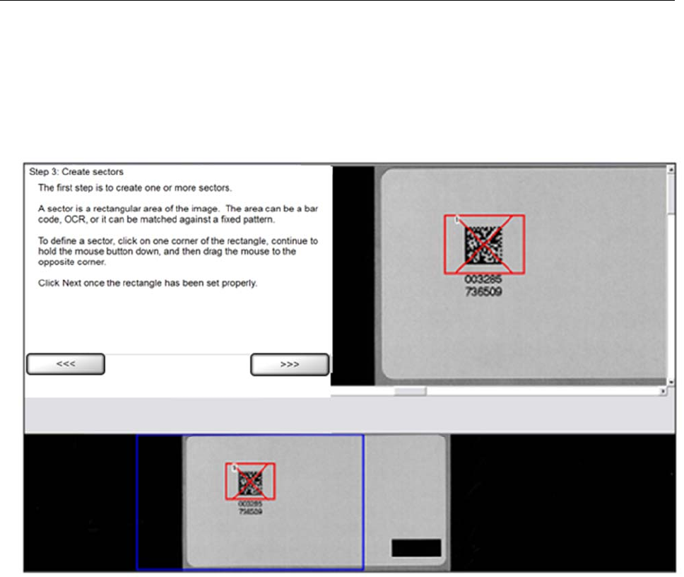
LVS-7510 Integrated System Operations Manual Version 20.2.X
LVS-7510 Integrated System Operations Manual Version 20.2.X Page 149 of 210
Appendix B: Epedigree
Systems with ePedigree enabled are using the normal LVS-7510 software with enhanced tracking features.
Below are a couple of steps that highlight the LVS-7510 ePedigree process.
1. When drawing a sector over a 2D Data Matrix code, make sure that the center of the X within the sector
is close to the center of the 2D code. This helps the software to determine the position of the barcode.
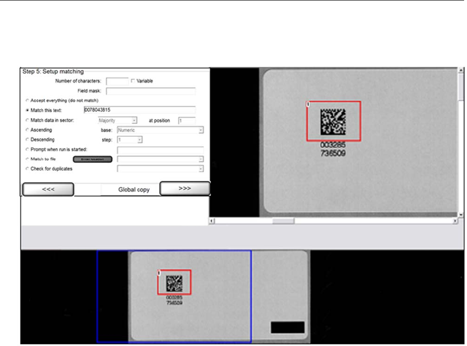
LVS-7510 Integrated System Operations Manual Version 20.2.X
LVS-7510 Integrated System Operations Manual Version 20.2.X Page 150 of 210
2. Choose the Check for Duplicates option to make sure that the barcode’s encoded data is unique for this
job or the sect. When running the job, a !DU error will show up if the software finds a duplicate of the
barcode.
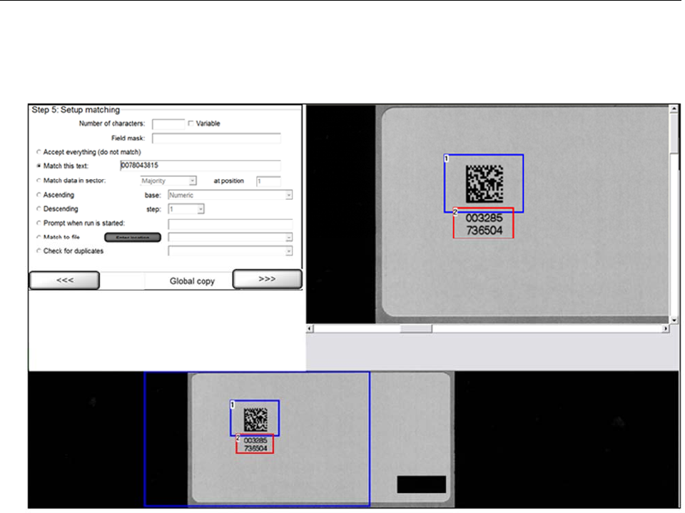
LVS-7510 Integrated System Operations Manual Version 20.2.X
LVS-7510 Integrated System Operations Manual Version 20.2.X Page 151 of 210
3. Draw an OCR sector around the human readable characters and let it match its corresponding barcode.
In this example, we have to start matching OCR at position 17 of the barcode, because the barcode is 28
characters long and the human readable characters match the last 12 characters of the barcode.
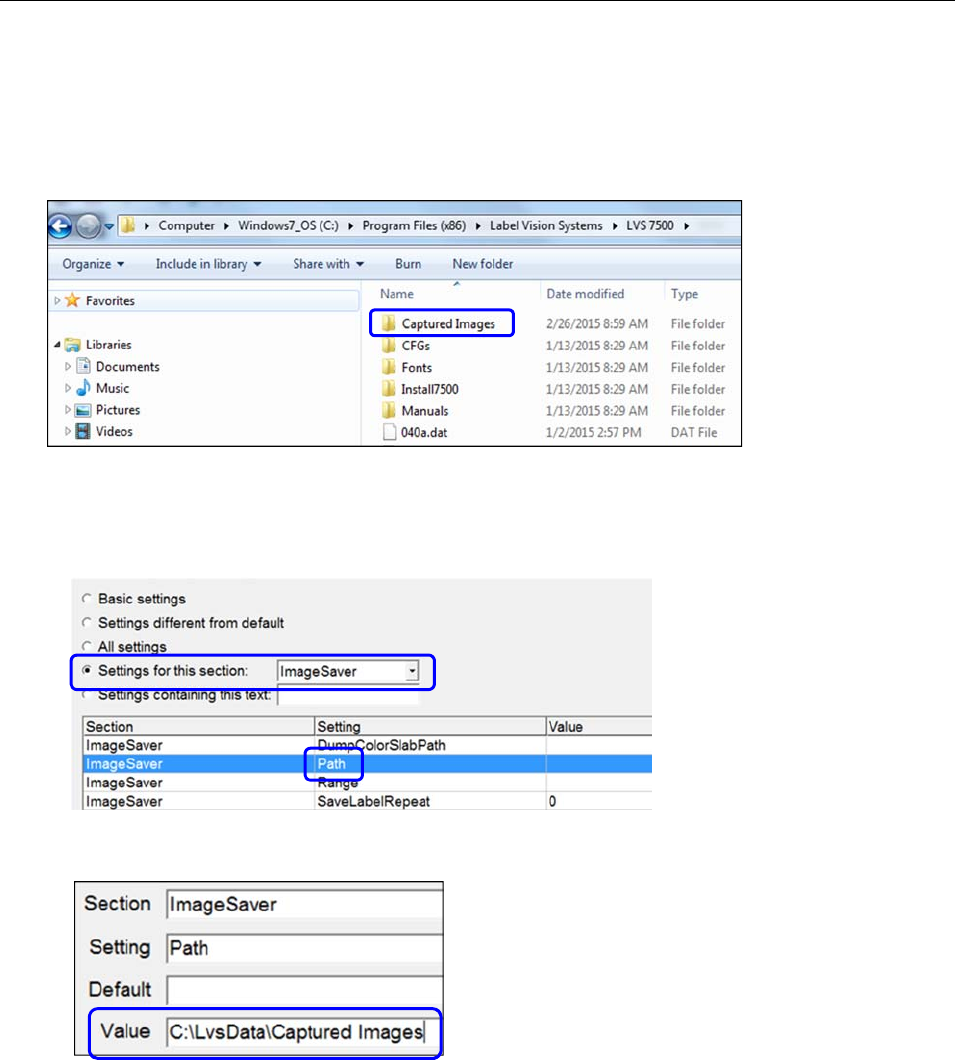
LVS-7510 Integrated System Operations Manual Version 20.2.X
LVS-7510 Integrated System Operations Manual Version 20.2.X Page 152 of 210
Appendix C: ImageSaver Instructions
Saving Raw Images Without a Label Repeat
1. Create and name a target folder where images can be saved (see below).
2. Open the LVS-7510 software and click “Settings” in the menu bar.
a. Select the “Settings for this section” radio button and select “ImageSaver” from the dropdown list
(see below).
b. Double-click “Path” located in the “Setting” column (see below).
c. In the “Value” field, enter the path of the folder that was created to store images. Then, click “OK
(save changes).”
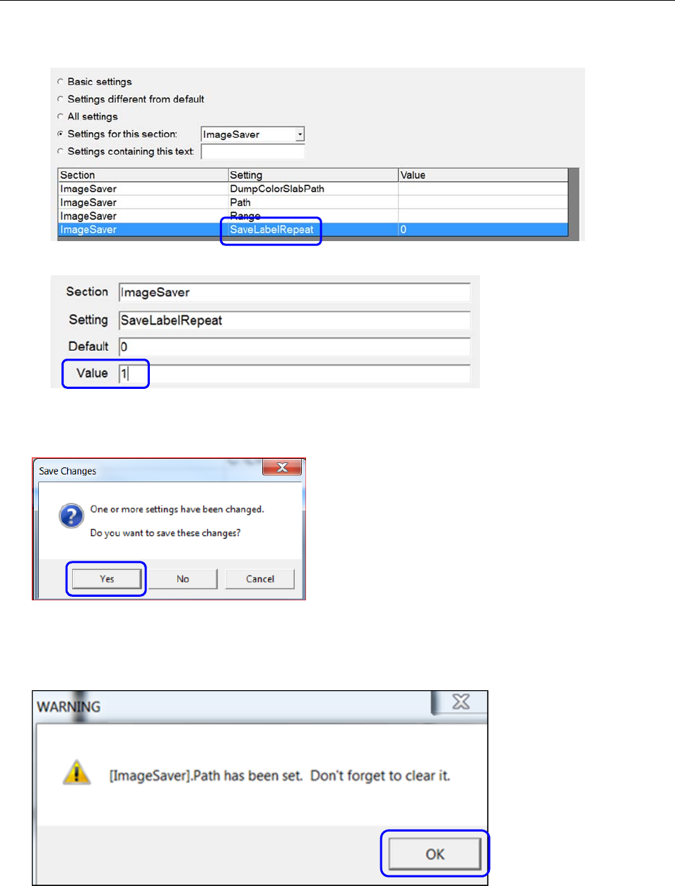
LVS-7510 Integrated System Operations Manual Version 20.2.X
LVS-7510 Integrated System Operations Manual Version 20.2.X Page 153 of 210
d. Double-click “SaveLabelRepeat.”
e. Type “1” in the “Value” field and click “OK (save changes).”
f. Close the “Settings” menu by clicking the red “X” in the top, right corner of the Configuration Editor
screen.
3. Click “Yes” to the “Save Changes” confirmation.
4. Close and then restart the LVS-7510 software.
5. Click “OK” at the ImageSaver warning.
Clearing the ImageSaver after capturing the desired images is important as it will continue to save
images causing the hard drive to fill up.
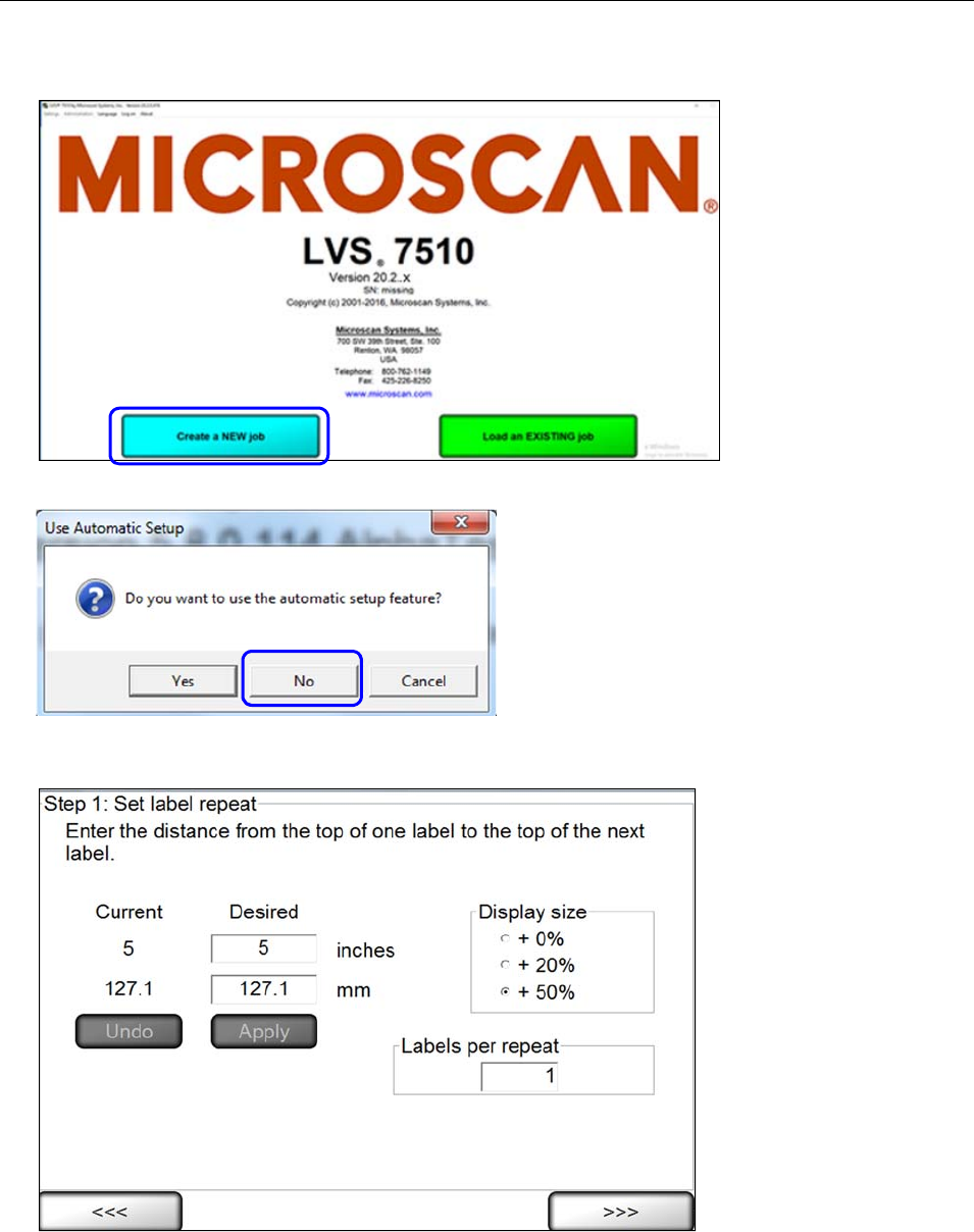
LVS-7510 Integrated System Operations Manual Version 20.2.X
LVS-7510 Integrated System Operations Manual Version 20.2.X Page 154 of 210
6. Click the “Create a New Job” button.
7. Select “No” when asked, “Do you want to use the automatic setup feature?”
8. Stay at the “Step 1: Set label repeat” screen (your settings may appear differently than the settings in the
image below).
9. Run the printer to obtain a desired amount of images. The system is capturing images although the
onscreen images may not immediately update.
10. Stop the job and close the LVS-7510 software; then, stop the printer.
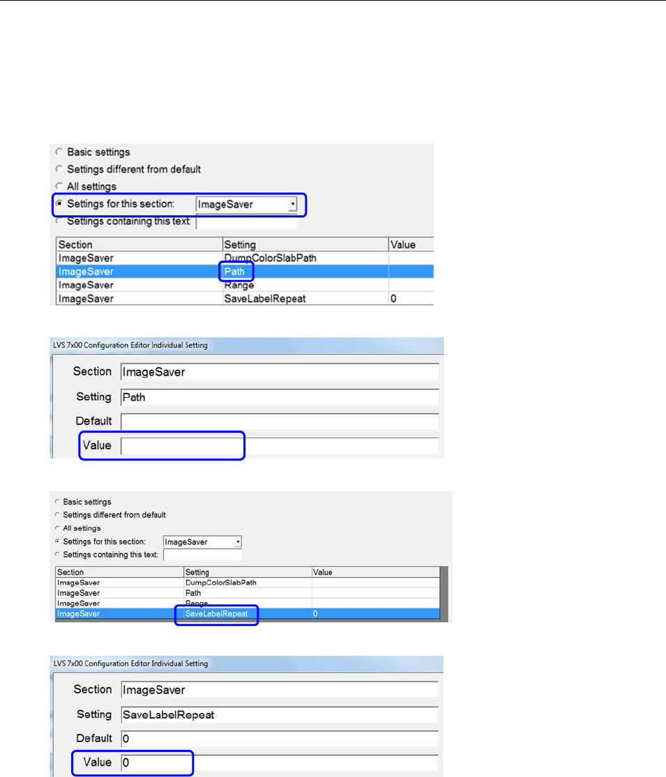
LVS-7510 Integrated System Operations Manual Version 20.2.X
LVS-7510 Integrated System Operations Manual Version 20.2.X Page 155 of 210
11. Navigate to the “captured images” folder (your folder may be named differently) that was created in Step
1 and the images should appear from the last job.
12. When image capturing is complete, click “Settings” in the menu bar.
a. Select the “Settings for this section” radio button and select “ImageSaver” from the dropdown list.
b. Double-click “Path” in the “Setting” column.
c. Delete the path in the “Value” field and save your changes.
d. Double-click “SaveLabelRepeat.”
e. Enter 0 (zero) in the “Value” field and then save your changes.
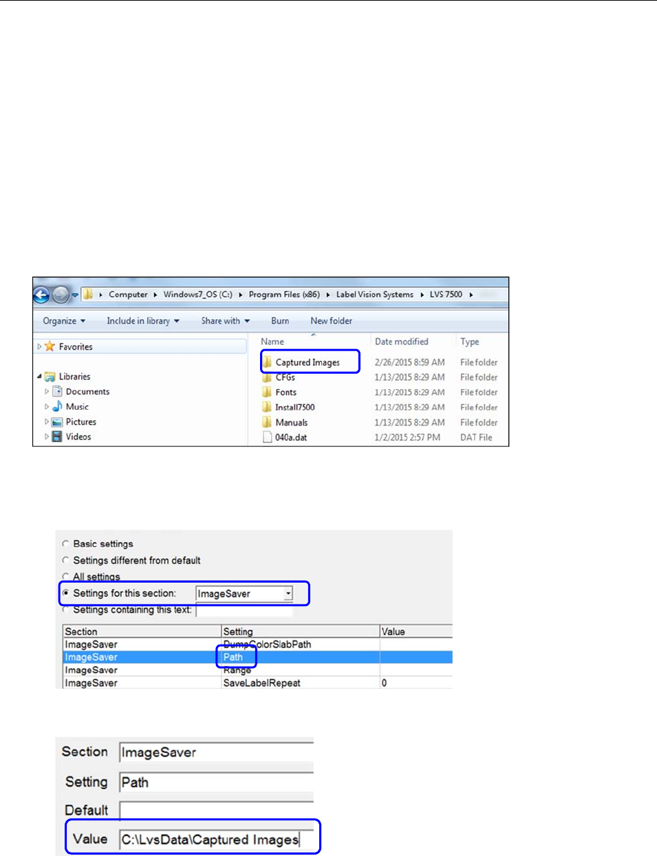
LVS-7510 Integrated System Operations Manual Version 20.2.X
LVS-7510 Integrated System Operations Manual Version 20.2.X Page 156 of 210
Saving Images WITH a Label Repeat
1. Open the LVS-7510 software and create a new job with the labels that you would like to capture.
2. Correctly synchronize the labels, define any sector, and save the job.
3. After the job is created, close the LVS-7510 software and stop the printer.
4. Open Windows Explorer and navigate to the LVS-7510 folder:
For installations of software version 20.2.X on Windows® 7 Professional and Windows® 8.1
Professional operating systems: C:\LvsData\LVS 7500
Jobs created in earlier versions of the software are not supported. Manually backup any desired
data and manually delete the C:\Users\[User Login Name]\AppData\Roaming\Label Vision
Systems\LVS 7500. Then, install software release 20.2.X as a new installation.
5. Create and name a target folder where images can be saved (see below).
6. Open the LVS-7510 software and click “Settings” in the menu bar.
a. Select the “Settings for this section” radio button and select “ImageSaver” from the dropdown list.
b. Double-click “Path” located in the “Setting” column (see below).
c. In the “Value” field, enter the path of the folder that was created to store images. Then, click “OK
(save changes).”
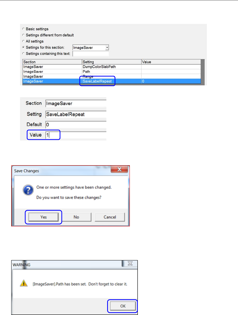
LVS-7510 Integrated System Operations Manual Version 20.2.X
LVS-7510 Integrated System Operations Manual Version 20.2.X Page 157 of 210
d. Double-click “SaveLabelRepeat.”
e. Type “1” in the “Value” field and then click “OK (save changes).”
f. Close the “Settings” menu by clicking the red “X” in the top, right corner of the Configuration Editor
screen.
7. Click “Yes” to the “Save Changes” confirmation.
8. Close and then restart the LVS-7510 software.
9. Click “OK” at the ImageSaver warning.
Clearing the ImageSaver after capturing the desired images is important as it will continue to save
images causing the hard drive to fill up.
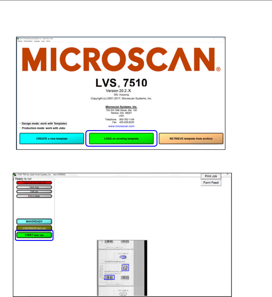
LVS-7510 Integrated System Operations Manual Version 20.2.X
LVS-7510 Integrated System Operations Manual Version 20.2.X Page 158 of 210
10. Click the “Load an Existing template” button and choose the template that was created for image
capturing.
11. After the template is loaded, click the “Start new run” button and jog the printer for a desired amount of
images. Each label repeat should be a full image.
12. Stop the printer.
13. Stop the job and close the LVS-7510 software.
14. Navigate to the “captured images” folder (your folder may be named differently) that was created in
Step 1 and the images should appear from the last job.
15. When image capturing is complete, click “Settings” in the menu bar.
a. Select the “Settings for this section” radio button and select “ImageSaver” from the dropdown list.
b. Double-click “Path” in the “Setting” column.
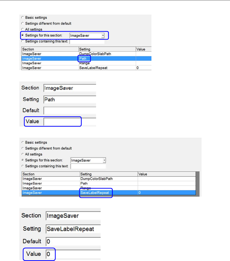
LVS-7510 Integrated System Operations Manual Version 20.2.X
LVS-7510 Integrated System Operations Manual Version 20.2.X Page 159 of 210
c. Delete the path in the “Value” field and save your changes.
d. Double-click “SaveLabelRepeat.”
e. Enter 0 (zero) in the “Value” field and then save your changes.
16. Remember to remove all excess images as they will quickly take up space on the hard drive.
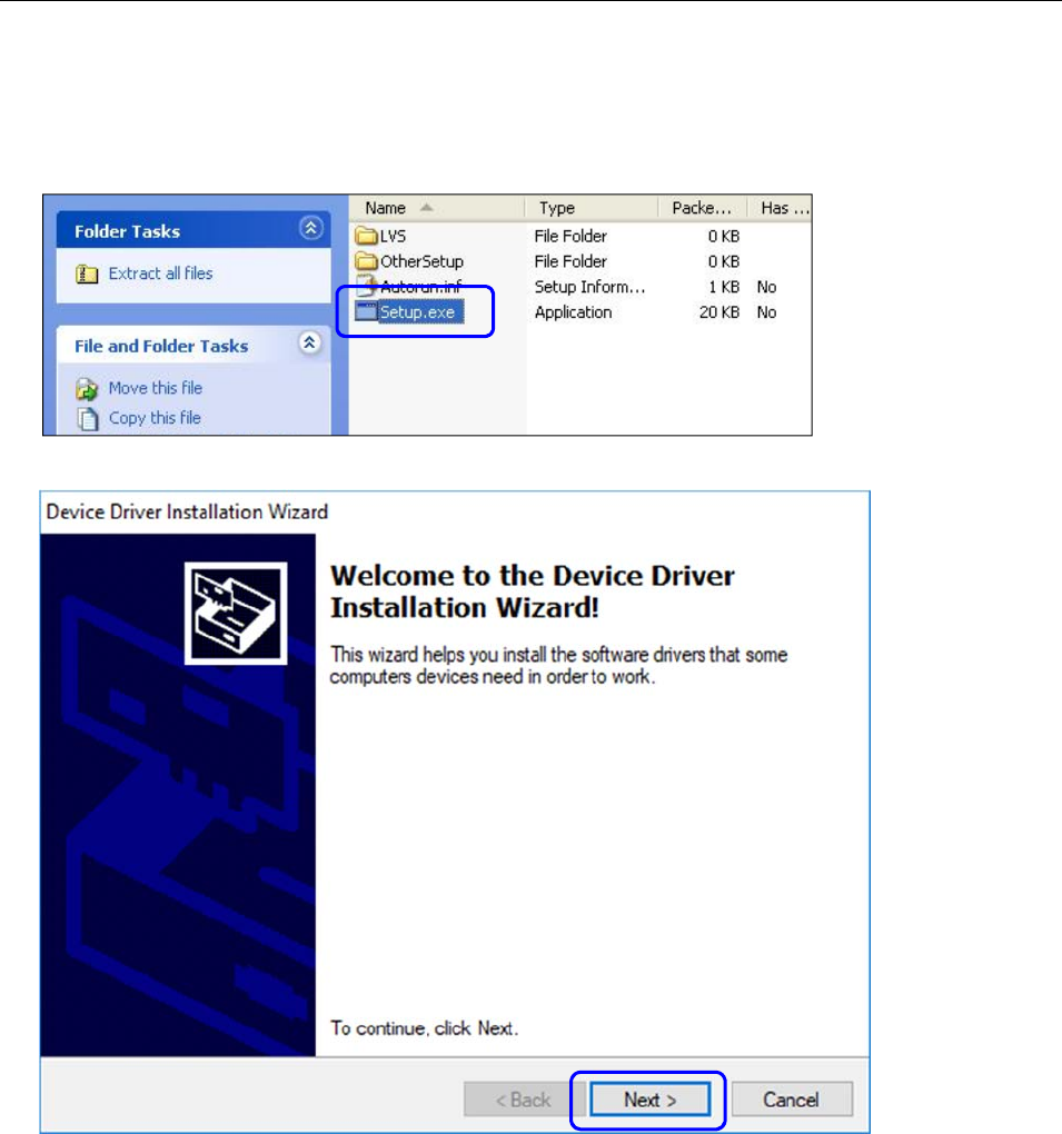
LVS-7510 Integrated System Operations Manual Version 20.2.X
LVS-7510 Integrated System Operations Manual Version 20.2.X Page 160 of 210
Appendix D: Upgrading Software
1. After receiving the LVS-7510 software files to download, open the .zip folder and double-click
“Setup.exe.”
2. Click “Next” to begin installation.
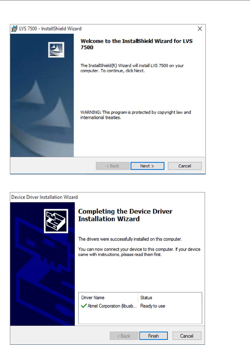
LVS-7510 Integrated System Operations Manual Version 20.2.X
LVS-7510 Integrated System Operations Manual Version 20.2.X Page 161 of 210
3. Click “Next” on the “LVS-7510 InstallShield Wizard” screen.
4. Click Finish to continue.
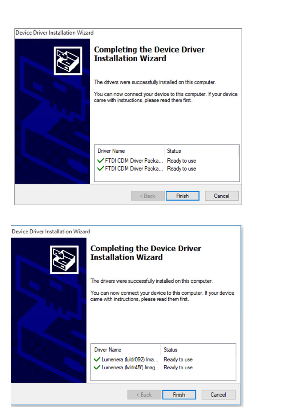
LVS-7510 Integrated System Operations Manual Version 20.2.X
LVS-7510 Integrated System Operations Manual Version 20.2.X Page 162 of 210
5. Click Finish again to continue.
6. Click Finish again to continue.
LVS-7510 Integrated System Operations Manual Version 20.2.X
LVS-7510 Integrated System Operations Manual Version 20.2.X Page 163 of 210
7. Installation begins, which may take several minutes to complete.
LVS-7510 Integrated System Operations Manual Version 20.2.X
LVS-7510 Integrated System Operations Manual Version 20.2.X Page 164 of 210
8. The “InstallShield Wizard Completed” window appears when installation is complete. Click “Finish.”
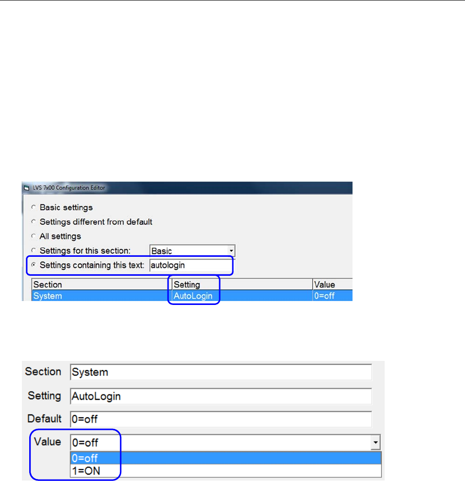
LVS-7510 Integrated System Operations Manual Version 20.2.X
LVS-7510 Integrated System Operations Manual Version 20.2.X Page 165 of 210
Appendix E: Automatic Login
The Automatic Login feature allows a user to automatically log in to the LVS-7510 software without entering
an Operator ID and Password.
Automatic Login Settings
Automatic Login settings are controlled in the “Settings” menu file:
1. Click “Settings” in the menu bar.
2. Type “autologin” (uppercase or lowercase letters) in the “Settings containing this text” field (see below).
3. Double-click “AutoLogin” in the “Setting” column.
4. In the “Value” field, select one of the following:
0=off – disables Automatic Login
1=On – enables Automatic Login
5. Click “OK (save changes).”
6. Click the red “X” in the top, right corner of the Configuration Editor screen.
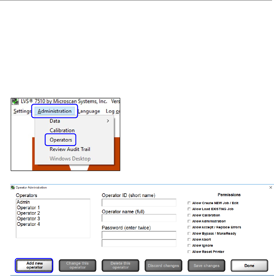
LVS-7510 Integrated System Operations Manual Version 20.2.X
LVS-7510 Integrated System Operations Manual Version 20.2.X Page 166 of 210
Automatic Login Instructions
When enabled, the LVS-7510 compares the current Windows user name to the list of LVS-7510 operator
names. If there is a match, and if the operator’s LVS-7510 password is set to “AUTO,” then the user will
automatically be logged in to the LVS-7510 software.
Automatic Login is attempted only when the LVS-7510 is first opened. If a user logs out of the LVS-7510,
then the next user is required to log in manually. If the operator closes the LVS-7510 entirely, then Automatic
Login will be attempted the next time the LVS-7510 software is launched.
To enable an operator to use Automatic Login, follow the steps below.
1. Click “Administration” > “Operators” from the menu bar.
2. On the “Operator Administration” screen, click the “Add new operator” button.
3. Enter the operator name in the “Operator ID (short name)” field and “Operator name (full)” field. The
Operator name must match the Windows user name.
4. Enter “AUTO” (all uppercase letters) in the “Password” field. Enter this password in each of the two
“Password” fields.
5. Select the desired operator permissions in the “Permissions” section.
6. Click the “Save Changes” button, and then click the “Done” button.
7. Close the LVS-7510 software by clicking the X in the top, right corner of the screen.
8. Log in to Windows as the user you just setup in the LVS-7510 software.
9. Open the LVS-7510 software. The user should automatically be logged in and the “Create a New Job” or
“Load an Existing Job” screen is visible. The user is not prompted to enter a user name or password.
10. See the “Create a New Job” section in this manual for detailed instructions on creating a new job. See
the “Load an Existing Job” section for detailed instructions on loading an existing job.
11. Close the LVS-7510 when work is complete.

LVS-7510 Integrated System Operations Manual Version 20.2.X
LVS-7510 Integrated System Operations Manual Version 20.2.X Page 167 of 210
12. Log off of Windows.
IMPORTANT: Automatic Login is only attempted when the LVS-7510 is first opened. If the
operator logs out of the LVS-7510, then the next user must log in manually. If the operator
closes the LVS-7510 entirely, then Automatic Login will be attempted the next time the LVS-
7510 software is launched.
In practice, an operator would follow the steps below:
a. Log in to Windows.
b. Launch the LVS-7510. Automatic Login executes for that Windows user name.
c. Run the LVS-7510 as needed.
d. Close the LVS-7510.
e. Log off of Windows.
f. The next operator repeats the above steps.

LVS-7510 Integrated System Operations Manual Version 20.2.X
LVS-7510 Integrated System Operations Manual Version 20.2.X Page 168 of 210
Appendix F: Managing Operator Permissions in
Microsoft® Active Directory
Overview
The LVS-7510 software integrates with Microsoft Active Directory to manage operator permissions. LVS-
7510 users are granted user privileges based on Microsoft authentication and LVS-7510 permissions are
assigned based on group membership in Omron Microscan specific Active Directory groups. All systems
using Active Directory must have a network of Microsoft® 2003 or later.
Active Directory control of LVS-7510 users provides a single, secure record of authentication and
authorization. Control of all Active Directory changes is managed through Active Directory Group policy and
ownership located on the Microsoft Server.
LVS-7510 operators can have a combination of permissions. Operator permissions are the same regardless
of how the user IDs, passwords and permissions are managed.
When Active Directory is enabled on each start of the LVS-7510 software, the system will connect over the
network to the specified Microsoft Active Directory domain controller. The LVS-7510 will create a local
Operators.dat file containing all of the LVS-7510 users and their permissions. All of the users created are in
the Active Directory Group specified in the LVS-7510 configuration setting “ActiveDirectoryLVSAllUsers.”
When Active Directory is enabled, user passwords, password expiration dates and failed password counts
are not stored locally in the Operator.dat file. Microsoft Active Directory policies will manage user password
restrictions and policies. When a user enters their user name and password into the LVS-7510, the
credentials are verified with the current user name and password in the Active Directory. The Operator
Administration window in the LVS-7510 can be used to view the current users and their permissions. When
users are disabled or deleted from Active Directory, their access to LVS-7510 login is immediately disabled
even if the LVS-7510 has not been restarted.
The login for “admin” is not managed in Active Directory and remains in the local Operator.dat file. All new
installations create a default administrator user with the User Name and Password set to “admin.” The
“admin” user password is stored locally to allow access to the system in case of network outages. This
provides the option of operating the LVS-7510 without Active Directory user authentication. With Active
Directory enabled, the admin user is the only user that can be modified using the LVS-7510 Operator
Administration interface. The admin user name and password can be changed and deleted if desired;
however, if the admin user name is changed or deleted and the system loses connection to the Active
Directory Server or Active Directory is disabled, then no user will exist that has access to enable Active
Directory or manage users in a standalone mode.
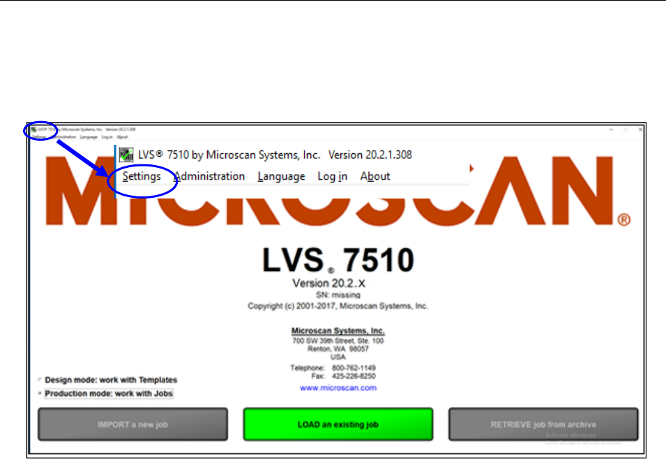
LVS-7510 Integrated System Operations Manual Version 20.2.X
LVS-7510 Integrated System Operations Manual Version 20.2.X Page 169 of 210
Enable Active Directory
1. Log in to the LVS-7510 software. You must have administrator rights to enable Active Directory.
2. Click Settings in the menu bar.
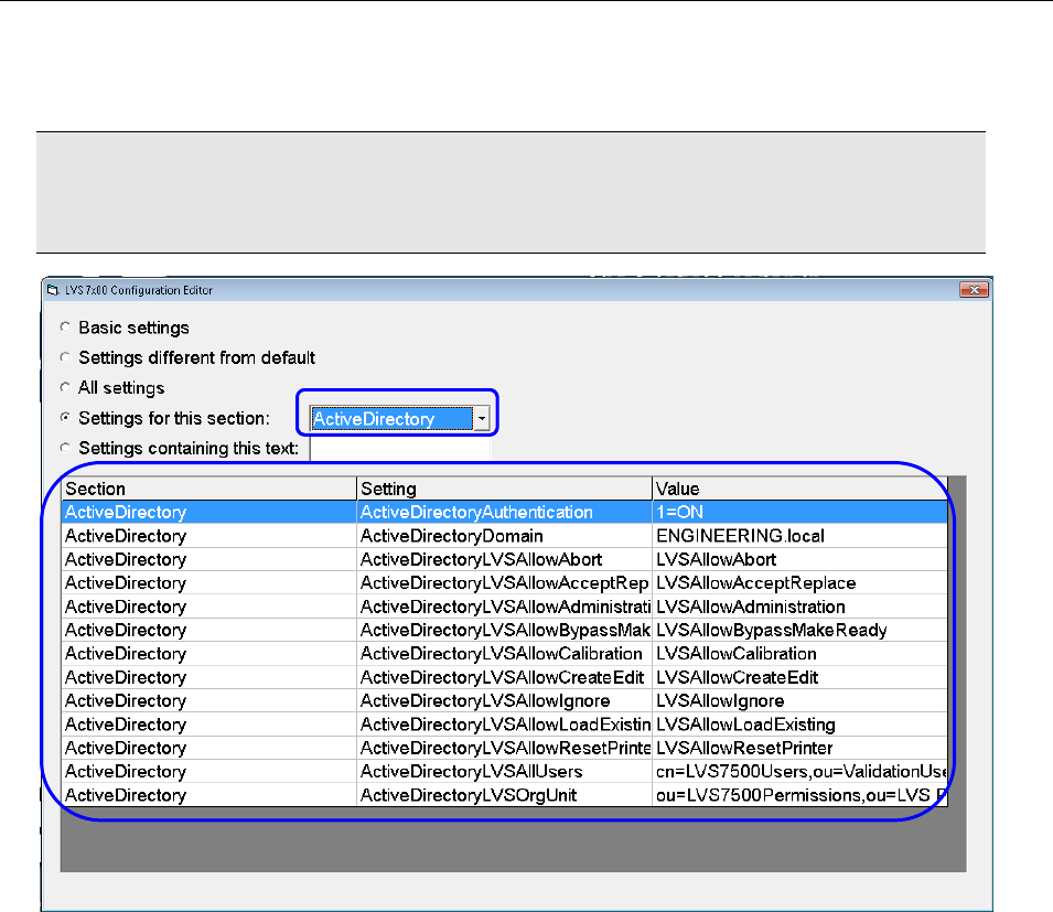
LVS-7510 Integrated System Operations Manual Version 20.2.X
LVS-7510 Integrated System Operations Manual Version 20.2.X Page 170 of 210
3. In the Settings containing this text field, type active. All Active Directory settings appear in the
“Setting” column and are preceded by “ActiveDirectory.”
IMPORTANT: ALL Active Directory settings must be configured for Active Directory to work
correctly. Refer to the “Active Directory Configuration Settings” section below for descriptions of
each setting.
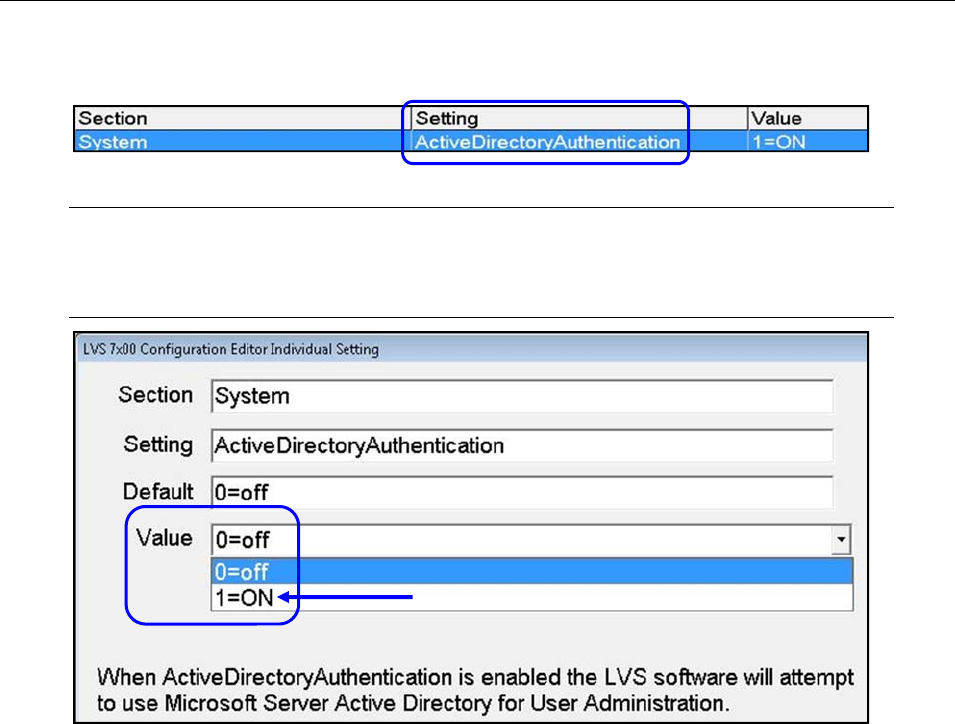
LVS-7510 Integrated System Operations Manual Version 20.2.X
LVS-7510 Integrated System Operations Manual Version 20.2.X Page 171 of 210
4. Double-click ActiveDirectoryAuthentication in the Setting column.
5. Click the Value drop-down box and select 1=ON.
Note: To disable Active Directory, select 0=off. When Active Directory is disabled, user
permissions are managed in the LVS-7510 software (for more information, refer to Welcome
Screen Overview Administration Operators).
6. Click the “OK (save changes)” button.
7. Click the “X” in the top right corner of the “LVS-7510 Configuration Editor” screen.
8. Click “Yes” to save changes in the “Save Changes” window.
9. Shut down and then restart the LVS-7510 software. Upon restart, Active Directory will be enabled.
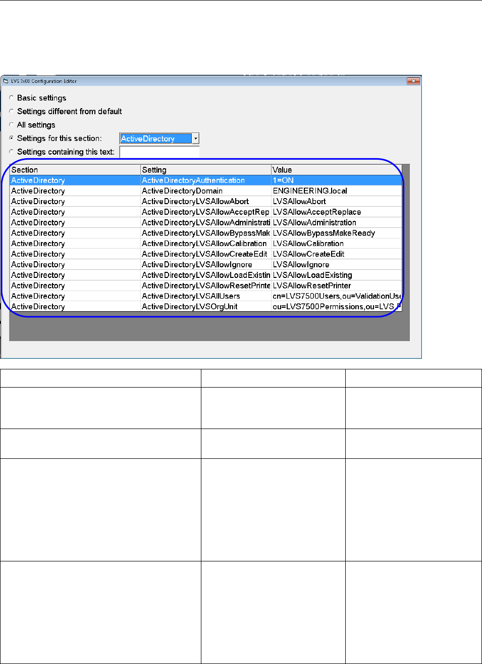
LVS-7510 Integrated System Operations Manual Version 20.2.X
LVS-7510 Integrated System Operations Manual Version 20.2.X Page 172 of 210
Active Directory Configuration Settings
Refer to the table below for a description of each Active Directory configuration setting.
Setting Description Options/Values/Examples
ActiveDirectoryAuthentication Enables Active Directory
control of users and user
permissions.
1=ON, 0=OFF
ActiveDirectoryDomain Name of the Microsoft®
Active Directory Domain Example value: lvs-inc.com
ActiveDirectoryLVSAllowAbort Allows the operator the ability
to abort the execution of a job
after a validation error is
detected and the “Printing
Stopped Error Message” is
displayed.
Active Directory Security
Group containing all users
or groups of users to be
granted “Allow Abort”
permission on the LVS-
7510 system.
Example:
LVSAllowAllowAbort
ActiveDirectoryLVSAllowAcceptReplace Allows the operator to accept
or replace errors. Active Directory Security
Group containing all users
or groups of users to be
granted “Allow Accept /
Replace Errors” permission
on the LVS-7510 system.
Example:
LVSAllowAcceptReplace

LVS-7510 Integrated System Operations Manual Version 20.2.X
LVS-7510 Integrated System Operations Manual Version 20.2.X Page 173 of 210
Setting Description Options/Values/Examples
ActiveDirectoryLVSAllowAdministration Allows the operator access to
the “Administration” menu bar
feature where operators and
operator permissions are
setup.
Active Directory Security
Group containing all users
or groups of users to be
granted “Allow
Administration” permission
on the LVS-7510 system.
Example:
LVSAllowAdministration
ActiveDirectoryLVSAllowBypassMakeRea
dy Allows the operator the ability
to use the “Bypass” and
“MakeReady” buttons on the
Running screen.
Active Directory Security
Group containing all users
or groups of users to be
granted “Allow Bypass /
MakeReady” permission on
the LVS-7510 system.
Example:
LVSAllowMakeReady
ActiveDirectoryLVSAllowCalibration Allows the operator to
perform calibration. Active Directory Security
Group containing all users
or groups of users to be
granted “Allow Calibration”
permission on the LVS-
7510 system.
Example:
LVSAllowCalibration
ActiveDirectoryLVSAllowCreateEdit Allows the operator to create,
edit and delete a job. Active Directory Security
Group containing all users
or groups of users to be
granted “Allow Create NEW
Job / Edit” permission on
the LVS-7510 system.
Example:
LVSAllowCreateEdit
The value entered should
be a member of the value
entered for
ActiveDirectoryLVSOrgUnit.
ActiveDirectoryLVSAllowIgnore Allow the operator the ability
to ignore a label validation
error after the “Printing
Stopped Error Message” is
displayed. Printing will
continue with the next label in
the job.
Active Directory Security
Group containing all users
or groups of users to be
granted “Allow Ignore”
permission on the LVS-
7510 system.
Example: LVSAllowIgnore
ActiveDirectoryLVSAllowLoadExisting Allows the operator to load
and execute existing jobs.
This permission does not
allowed to user to edit
existing jobs.
Active Directory Security
Group containing all users
or groups of users to be
granted “Allow Load

LVS-7510 Integrated System Operations Manual Version 20.2.X
LVS-7510 Integrated System Operations Manual Version 20.2.X Page 174 of 210
Setting Description Options/Values/Examples
EXISTING Job” permission
on the LVS-7510 system.
Example:
LVSAllowLoadExisting
The value entered should
be a member of the value
entered for
ActiveDirectoryLVSOrgUnit.
ActiveDirectoryLVSAllowResetPrinter Allows the operator to send a
reset printer signal from the
LVS-7510 to the connected
printer.
Active Directory Security
Group containing all users
or groups of users to be
granted “Allow Reset
Printer” permission on the
LVS-7510 system.
Example:
LVSAllowResetPrinter
ActiveDirectoryLVSAllUsers Group containing all domain
users to be granted
permissions on the LVS-
7510.
Active Directory Security
Group containing all users
to be created on the LVS-
7510 system.
Example: LVS7500Users
The value entered can be
located outside of the
Omron Microscan
Organizational Unit object if
desired. The full path
should be provided using
standard Active Directory
object naming syntax. See
“Example 1” below for more
information.
Example:
cn=LVS7500Users,ou=Vali
dationUsers.
ActiveDirectoryLVSOrgUnit Logical Organizational Unit
that contains all of the Omron
Microscan Permission
Groups.
Active Directory
Organizational Unit
containing all of the other
LVS-7510 Permission
Groups. The full path
should be provided using
standard Active Directory
object naming syntax. See
“Example 2” below for more
information.
Example:
ou=LVS7500Permissions,o
u=LVS
Permissions,ou=LVS
Systems
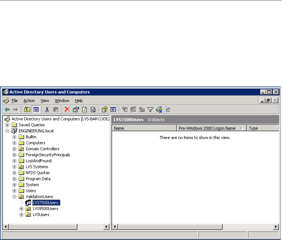
LVS-7510 Integrated System Operations Manual Version 20.2.X
LVS-7510 Integrated System Operations Manual Version 20.2.X Page 175 of 210
Example 1:
The entry for ActiveDirectoryLVSAllUsers must be formatted using standard Active Directory syntax. For
example:
LVS7500Users is a Group and begins with cn=
ValidationUsers is an Organizational Unit and begins with ou=
cn=LVS7500Users,ou=ValidationUsers
The above example is correct given the objects displayed in the following Active Directory window:
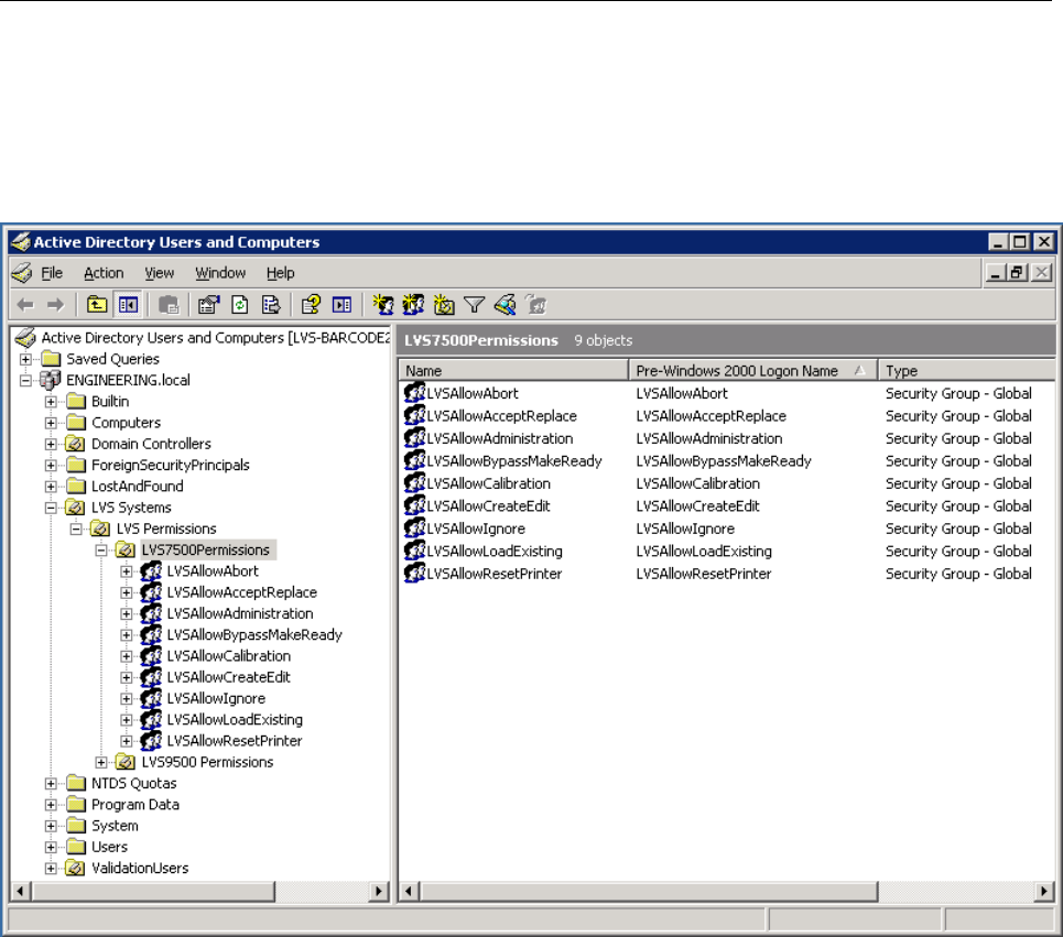
LVS-7510 Integrated System Operations Manual Version 20.2.X
LVS-7510 Integrated System Operations Manual Version 20.2.X Page 176 of 210
Example 2:
The entry for ActiveDirectoryLVSOrgUnit must be formatted using standard Active Directory syntax. The
example below is correct given the objects displayed in the Active Directory window below.
ou=LVS7500Permissions,ou=LVS Permissions,ou=LVS Systems
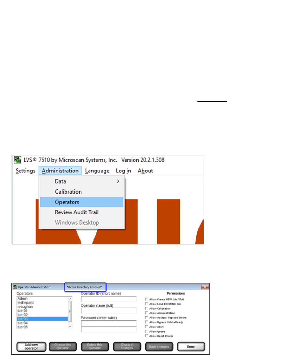
LVS-7510 Integrated System Operations Manual Version 20.2.X
LVS-7510 Integrated System Operations Manual Version 20.2.X Page 177 of 210
Active Directory User Permissions
When Microsoft
®
Active Directory (AD) is enabled the LVS-7510 user permissions are managed in AD. Also,
user passwords, password expiration dates, and failed password counts are managed in AD.
The default administrator account (admin) is a special, unique login. It is not managed in AD and remains in
the local LVS-7510 system database. All new installations create a default administrator user with the User
Name and Password set to admin. The admin user password is stored in the local LVS-7510 system
database to allow access to the system in case there is a network outage. This provides the option of
operating the system without AD user authentication. With AD enabled, the admin user is the only user that
can be modified using the LVS-7510 system Operator Administration interface. The admin user name and
password can be changed and deleted if desired; however, if the admin user name is changed or deleted
and the system loses connection to the Active Directory Server or Active Directory is disabled, then no user
will exist who has access to enable Active Directory or manage users in a standalone mode.
When AD is enabled the Operator Administration screen allows you to only view the operators and
operator permissions which were created from Microsoft
®
Active Directory settings. Operator names,
permissions and passwords cannot be changed from the LVS-7510 Operator Administration interface.
1. Select Administration Operators from the menu bar.
2. When Active Directory is enabled, the Operator Administration screen allows you to view the operators
and operator permissions which were created from Active Directory settings.
*Active Directory Enabled* appears at the top of the screen to let you know that Active Directory is
enabled; this message does not appear when Active Directory is disabled.
3. The buttons at the bottom of the Operator Administration screen are grayed out and disabled to prevent
changes to users from the LVS-7510 software. The exception is the Admin user account, it can be
modified using the Operator Administration screen.
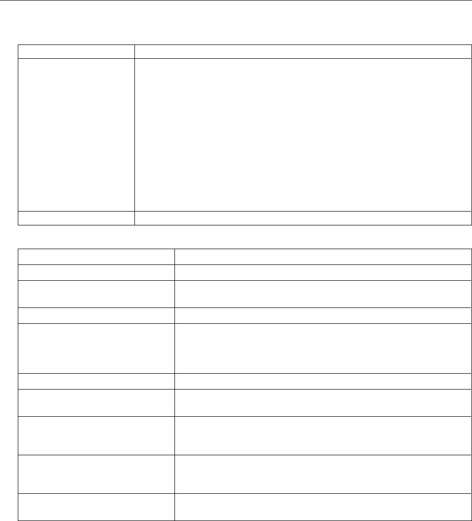
LVS-7510 Integrated System Operations Manual Version 20.2.X
LVS-7510 Integrated System Operations Manual Version 20.2.X Page 178 of 210
4. The buttons available at the bottom of the screen are described below.
Option Description
Add new operator Click this button to add a new operator. Complete the following fields:
Operator ID (short name)
Operator name (full name)
Password (enter twice). Each password must consist of the
following:
o At least 8 characters
o At least 1 letter from A to Z
o At least 1 number from 0 to 9
Select the desired permissions
Click Save changes to save your changes or Discard changes to
discard and not save your changes
Done Click this button after all changes are complete.
5. User permissions are described below:
Permission Description
Allow Create / Edit NEW Job Allows the operator to create, edit, and delete a job.
Allow Load EXISTING Job Allows the operator to load and execute existing jobs. This
permission does not allow the user to edit existing jobs.
Allow Calibration Allows the operator to perform calibration.
Allow Administration Allows the operator access to the “Administration” menu bar
feature where operators and operator permissions are set up.
See the “Administration” section for more information (Welcome
Screen Overview > Administration)
Allow Accept / Replace Errors Allows the operator to accept or replace errors.
Allow Bypass / MakeReady Allows the operator the ability to use the “Bypass” and
“MakeReady” buttons on the Running screen.
Allow Abort Allows the operator the ability to abort the execution of a job after
a validation error is detected and the “Printing Stopped Error
Message” is displayed.
Allow Ignore Allows the operator the ability to ignore a label validation error
after the “Printing Stopped Error Message” is displayed. Printing
will continue with the next label in the job.
Allow Reset Printer Allows the operator to send a reset printer signal from the LVS-
7510 to the connected printer.

LVS-7510 Integrated System Operations Manual Version 20.2.X
LVS-7510 Integrated System Operations Manual Version 20.2.X Page 179 of 210
Appendix G: TCP/IP Control
Basic Production mode functionality of the LVS-7510 can be controlled using a TCP/IP command set. This
provides customers and third party integrators a mechanism for developing custom HMI interfaces using
TCP/IP bi-directional communication with the LVS-7510 system to automate production job execution. To
prepare the LVS-7510 system to accept TCP/IP commands, there are user configurable software settings;
refer to the following section for details on implementing the required settings: Appendix A: User
Configurable Settings List of User Configurable Settings TCP/IP.
TCP/IP Configuration Settings
Setting: Host
Options: none
Default: 0.0.0.0
Leave as default value.
Setting: Mode
Options: off
Remote
XML
Default: off
Mode indicates if the LVS-7510 is connecting to another system. Use “off” if the
LVS-7510 is not connecting to another system. Use “Remote” if the LVS-7510 is
connecting with a remote computer, such as the Omron Microscan HMI
Command Center or a non-Omron Microscan system. All remaining settings
(such as Host, Port1, Port2, etc.) do not apply if the LVS-7510 is not connecting
to another system.
Setting: Port1
Options: none
Default: 0
Enter the port where the first external system will be listening for Omron
Microscan data.
Setting:
Port1Filt
er
Options: none
Default: none
Specifies the type of information that the LVS-7510 system will broadcast on the
port specified by Port1. This filter is for output from the LVS-7510 only.
Leave this blank to receive all information from the LVS-7510 system.
Enter a comma separated list of Binary Command Byte ID#’s to receive only the
feedback information desired.
Setting: Port2
Options: none
Default: 0
Enter the port where the second external system will be listening for Omron
Microscan data.
Setting:
Port2Filt
er
Options: none
Default: none
Specifies the type of information that the LVS-7510 system will broadcast on the
port specified by Port2. This filter is for output from the LVS-7510 only.
Leave this blank to receive all information from the LVS-7510 system.
Enter a comma separated list of Binary Command Byte ID#’s to receive only the
feedback information desired.
Below is an example of the setting to configure an LVS-7510 to accept TCP/IP commands:
Mode=remote
Host=0.0.0.0
Port1=8001
Port1Filter=1,2,3,4,5,7,8,11,12,13,14,28,29
The example for Port1Filter will tell the LVS-7510 to broadcast all outputs and input command responses
except the IP Status (31).

LVS-7510 Integrated System Operations Manual Version 20.2.X
LVS-7510 Integrated System Operations Manual Version 20.2.X Page 180 of 210
TCP/IP Commands and Output Data Summary
Name Binary
Command
Byte ID#
Description External
Command Data
Output
Load Job 1 Load the currently loaded job. X
Start Run 2 Start running the currently loaded job. X
Stop Run 3 Stop running. X
Start Bypass 4 Enter Bypass mode if the system is currently
running. X
End Bypass 5 Exit from Bypass mode. X
Sector Error 7 Data output from the LVS-7510 system with this
command byte ID# will include information about a
failed sector inspection. If multiple sectors fail
during a given repeat, there will be a unique sector
error output message for each individual sector.
X
Log Line 8 Data output from the LVS-7510 system with this
command byte ID# will include all inspection
information from every sector for the given repeat.
X
Continue Run 11 Continue the last run of the currently loaded job. X
Make Ready 12 Enter Make Ready mode. X
Reset Alarms 13 Reset the alarms. X
Exit To Main 14 Exit from the currently loaded job to the main
screen. X
Close out job 15 Close out the currently loaded job. X
Import Job 16 Import the job from the Import folder. X
Load Job
from Archive 17 Load job from the Archive folder. X
Set Match to
File Path 18 Set the match to file path when a match to file
is in use
X
Set MatchTo 28 Enter the current match-to strings to replace the
given field designator. X
Reset
Available 29 Query the LVS-7510 system to discover if the
Reset Alarms button is active (used prior to a
Reset Alarms command).
X
IP Status 31 Continuous status data updates from the LVS-
7510 system. X

LVS-7510 Integrated System Operations Manual Version 20.2.X
LVS-7510 Integrated System Operations Manual Version 20.2.X Page 181 of 210
TCP/IP Commands Protocol
The TCP/IP Commands sent to an LVS-7510 have the following format:
<Binary Command Byte ID#><ASCII String>
Where:
<Binary Command Byte ID#> is the unique command ID associated with the desired operation. Refer
to the following sections for the binary command byte IDs for each support LVS-7510 command. The
commands are sent as binary bytes not ASCII. An example of a binary command to import a job would
be a byte value 0x16 hex. The production command to import a job is: 0x16 “Jobname0221.”
<ASCII String> consists of command-specific data, if applicable. An example of command-specific data
in the previous example would be the job name. The text string “Jobname0221” is the job name and
would be loaded if it existed in the Import folder.
The response from the LVS-7510 system will have the following format if the operation is successful:
<Binary Command Byte ID#>
Where <Binary Command Byte ID#> will be identical to the command ID that the LVS-7510 received. For
example, if the command to import a job named “Jobname0221” was sent.
0x16 “Jobname0221”
If the job was successfully imported the response from the LVS-7510 would be the command byte that was
sent: 0x16
The response from the LVS-7510 will have the following format if the operation fails:
<Binary Command Byte ID#><ASCII String>
<Binary Command Byte ID#> will be identical to the command ID that the LVS-7510 received.
<ASCII String> is an ASCII string describing the error. If the job name did not exist in the Import folder, the
response from the LVS-7510 would be:
0x16 ERROR: Job not found in import folder

LVS-7510 Integrated System Operations Manual Version 20.2.X
LVS-7510 Integrated System Operations Manual Version 20.2.X Page 182 of 210
Load Job
The “Load Job” command will load the desired job on all connected LVS-7510 systems. The command
format is:
<Binary Command Byte ID#><ASCII String>
For the “Load Job” command, the <Binary Command Byte ID#> is equal to a binary 1 (0x01 hex), and the
<ASCII String> designates the name of an existing job. The command format is then:
<0x01 hex><Existing Job Name>
The LVS-7510 response when the command completes successfully would be:
<0x01 hex>
The LVS-7510 response when the command fails would be:
<0x01 hex><ASCII Error Message>
Start Running
The “Start Running” command will start the currently loaded job on the LVS-7510 system. The command
format is:
<Binary Command Byte ID#><ASCII String>
For the “Start Job” command, the <Binary Command Byte ID#> is equal to a binary 2 (0x02 hex), and the
<ASCII String> is blank. The command format is then:
<0x02 hex>
The LVS-7510 response when the command completes successfully would be:
<0x02 hex>
The LVS-7510 response when the command fails would be:
<0x02 hex><ASCII Error Message>
Stop Running
The “Stop Running” command will stop the desired job on the LVS-7510 system. The command format is:
<Binary Command Byte ID#><ASCII String>
For the “Stop Running” command, the <Binary Command Byte ID#> is equal to a binary 3 (0x03 hex), and
the <ASCII String> is blank. The command format is then:
<0x03 hex>
The LVS-7510 response when the command completes successfully would be:
<0x03 hex>
The LVS-7510 response when the command fails would be:
<0x03 hex><ASCII Error Message>
Continue Last Run
The “Continue Last Run” command is valid only after a job has been loaded. Sending this command will
initiate inspections and the results will be appended to the most recent run file (CSV file) instead of creating
a new run. The command format is:
<Binary Command Byte ID#>

LVS-7510 Integrated System Operations Manual Version 20.2.X
LVS-7510 Integrated System Operations Manual Version 20.2.X Page 183 of 210
For the “Continue Last Run” command, the <Binary Command Byte ID#> is equal to a binary 11 (0x0b hex),
and the <ASCII String> is blank. The command format is then:
<0x0b hex>
The LVS-7510 response when the command completes successfully would be:
<0x02 hex>
The LVS-7510 response when the command fails would be:
<0x0b hex><ASCII Error Message>
Make Ready
The “Make Ready” command is valid only after a job has been loaded. Sending this command will load
initiate Make Ready mode for the currently loaded job. The command format is:
<Binary Command Byte ID#>
For the “Make Ready” command, the <Binary Command Byte ID#> is equal to a binary 12 (0x0c hex), and
the <ASCII String> is blank. The command format is then:
<0x0c hex>
The LVS-7510 response when the command completes successfully would be:
<0x0c hex>
The LVS-7510 response when the command fails would be:
<0x0c hex><ASCII Error Message>
Start Bypass
The “Start Bypass” command is valid only after a job has been loaded and is currently running. Sending this
command will put the LVS-7510 system into Bypass mode. The command format is:
<Binary Command Byte ID#><ASCII String>
For the “Start Bypass” command, the <Binary Command Byte ID#> is equal to a binary 4 (0x04 hex), and the
<ASCII String> is blank. The command format is then:
<0x04 hex>
The LVS-7510 response when the command completes successfully would be:
<0x04 hex>
The LVS-7510 response when the command fails would be:
<0x04 hex><ASCII Error Message>
End Bypass
The “End Bypass” command is valid only after a job has been loaded and is currently running in Bypass
mode. Sending this command will take the LVS-7510 system out of Bypass mode and back into normal run
mode. The command format is:
<Binary Command Byte ID#><ASCII String>
For the “End Bypass” command, the <Binary Command Byte ID#> is equal to a binary 5 (0x05 hex), and the
<ASCII String> is blank. The command format is then:
<0x05 hex>
The LVS-7510 response when the command completes successfully would be:

LVS-7510 Integrated System Operations Manual Version 20.2.X
LVS-7510 Integrated System Operations Manual Version 20.2.X Page 184 of 210
<0x05 hex>
The LVS-7510 response when the command fails would be:
<0x05 hex><ASCII Error Message>
Reset Alarms
The “Reset Alarms” command is the equivalent of clicking the “Reset alarms” button on the LVS-7510
system. The command format is:
<Binary Command Byte ID#><ASCII String>
For the “Reset Alarms” command, the <Binary Command Byte ID#> is equal to a binary 13 (0x0d hex), and
the <ASCII String> is blank. The command format is then:
<0x0d hex>
The LVS-7510 response when the command completes successfully would be:
<0x0d hex>
The LVS-7510 response when the command fails would be:
<0x0d hex><ASCII Error Message>
Note: The LVS-7510 system will send a TCP/IP packet containing the “Reset Available” binary command
byte whenever the Reset button is available to the user. This occurs when an error is detected and the alarm
is triggered. The “Reset Available” binary command byte ID is a binary 29 (0x1d hex). The “Reset Alarms”
command will be ignored until the LVS-7510 sends the “Reset Available” message via TCP/IP.
Exit To Main
The “Exit To Main” command is valid only after a job has been loaded and is not currently running nor in
Bypass or MakeReady mode. Sending this command will return the LVS-7510 system to the main Welcome
window. The command format is:
<Binary Command Byte ID#><ASCII String>
For the “Exit To Main” command, the <Binary Command Byte ID#> is equal to a binary 14 (0x0e hex), and
the <ASCII String> is blank. The command format is then:
<0x0e hex>
The LVS-7510 response when the command completes successfully would be:
<0x0e hex>
The LVS-7510 response when the command fails would be:
<0x0e hex><ASCII Error Message>
Close Out Job
The “Close Out Job” command will close the currently loaded job on all connected LVS-7510 systems. All
job-related files are zipped up, removed from the Jobs folder and the jobname.zip file is move to the Archive
folder. The command format is:
<Binary Command Byte ID#><ASCII String>
For the “Close Out Job” command, the <Binary Command Byte ID#> is equal to a binary 1 (0x0f hex), and
the <ASCII String> is blank. The command format is then:
<0x0f hex>
The LVS-7510 response when the command completes successfully would be:
<0x0f hex>

LVS-7510 Integrated System Operations Manual Version 20.2.X
LVS-7510 Integrated System Operations Manual Version 20.2.X Page 185 of 210
The LVS-7510 response when the command fails would be:
<0x0f hex><ASCII Error Message>
Import Job
The “Import Job” command will import the desired job on all connected LVS-7510 systems. The command
format is:
<Binary Command Byte ID#><ASCII String>
For the “Import Job” command, the <Binary Command Byte ID#> is equal to a binary 16 (0x10 hex), and the
<ASCII String> designates the name of an existing job. The command format is then:
<0x10 hex><Job Name to import>
The LVS-7510 response when the command completes successfully would be:
<0x10 hex>
The LVS-7510 response when the command fails would be:
<0x10 hex><ASCII Error Message>
Load Job From Archive
The “Load Job from Archive” command will recall the desired job from the Archive folder onto all connected
LVS-7510 systems. The command format is:
<Binary Command Byte ID#><ASCII String>
For the “Load Job from Archive” command, the <Binary Command Byte ID#> is equal to a binary 17 (0x11
hex), and the <ASCII String> designates the name of a job in the Archive folder. The command format is
then:
<0x11 hex><Job Name from Archive>
The LVS-7510 response when the command completes successfully would be:
<0x11 hex>
The LVS-7510 response when the command fails would be:
<0x11 hex><ASCII Error Message>
Set Match To
The “Set Match To” command sets the “Match this text” string of OCR, OCV, barcode grade or barcode read
sectors. To use this feature, a field designator text string is entered into the “Match this text” setting in each
sector. The field designator is a unique string identifier that is replaced at runtime when the “Set Match To”
command is sent to the LVS-7510 system. Multiple sectors may have the same field designator entered in
the “Match this text” field. The command format is:
<Binary Command Byte ID#><ASCII String>
For the “Set Match To” command, the <Binary Command Byte ID#> is equal to a binary 28 (0x1c hex), and
the <ASCII String> indicates the name of the field designator and the desired match to string separated by
the vertical bar character “|”. The command format is then:
<0x1c hex><Field Designator Name>|<Match To String>
The LVS-7510 response when the command completes successfully would be:
<0x1c hex>
The LVS-7510 response when the command fails would be:
<0x1c hex><ASCII Error Message>
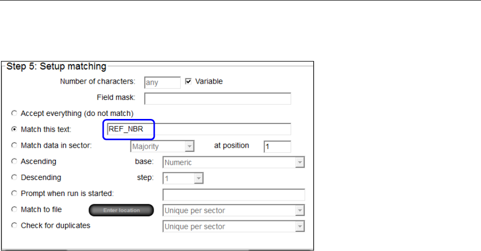
LVS-7510 Integrated System Operations Manual Version 20.2.X
LVS-7510 Integrated System Operations Manual Version 20.2.X Page 186 of 210
Example: The field designator “REF_NBR” has already been entered in the “Match this text” field for the
desired sectors in the job.
To replace the field designator “REF_NBR” with “ABC123” at run time send the following “Set Match To”
command:
<0x01c hex><”REF_NBR|ABC123”>
The field designator can be any string up to 25 characters as long as the Match To command contains the
exact same string as the Field Designator Name.
Set the Match to file path
The “Set Match to File Path” command will set the match to file path when a match to file
is in use. Send the full path including directory path. The command format is:
.
<Binary Command Byte ID#><ASCII String>
For the “Set Match to File Path” command, the <Binary Command Byte ID#> is equal to a
binary 18 (0x12 hex), and the <ASCII String> designates the full path to an existing match
to file including file name and extension. The command format is then:
<0x12 hex><Match to file path>
The LVS® 7X00 response when the command completes successfully would be:
<0x12 hex><ASCII NULL (0x00 hex)>
The LVS® 7X00 response when the command fails would be:
<0x12 hex><ASCII Error Message><ASCII NULL (0x00 hex)>

LVS-7510 Integrated System Operations Manual Version 20.2.X
LVS-7510 Integrated System Operations Manual Version 20.2.X Page 187 of 210
TCP/IP Output Data Protocol
Output data from the LVS-7510 is broadcast upon the occurrence of an event, such as an error in a sector
inspection. The connected system can choose to use the data as it sees fit.
The TCP/IP data output from the LVS-7510 have the following general format:
<Binary Command Byte ID#><ASCII String>
<Binary Command Byte ID#> is the unique command ID associated with the particular data contained in
the output – and – <ASCII String> consists of command-specific data (if any).
Sector Error
The “Sector Error” data output occurs for each sector that fails an inspection. The repeat number, timestamp
and distance are sent along with the sector ID number, the special error marker character (ASCII 161) and
error code, and any other sector-specific data. The command format is:
<Binary Command Byte ID#><ASCII String>
For the “Sector Error” command, the <Binary Command Byte ID#> is equal to a binary 7 (0x07 hex), and the
<ASCII String> is given below. The data output format is then:
<0x07 hex><ASCII String>
Where the comma separated ASCII String =
<RepeatNumber>,<Timestamp>,<Distance>,<SectorID>,<ErrorMarker><SectorResultData>
Note: There is no comma between the special error marker character (ASCII 161) and the sector results
data.
Log Line
The “Log Line” data output occurs once for each repeat and includes all of the data stored in the run file for
that repeat, including all sector inspection results. The repeat number, timestamp and distance are sent
along with the inspection results for each sector starting with sector #1 and continuing through the last sector
present. The special error marker character (ASCII 161) is inserted immediately prior to the sector result
data for any sector that fails an inspection. The command format is:
<Binary Command Byte ID#><ASCII String>
For the “Log Line” command, the <Binary Command Byte ID#> is equal to a binary 8 (0x08 hex), and the
<ASCII String> is given below. The data output format is then:
<0x08 hex><ASCII String>
Where the comma separated ASCII String =
<RepeatNumber>,<Timestamp>,<Distance>,<Sector 1 ResultData>,<Sector 1 ResultData>, ….. , <Sector
X ResultData>
Note: If one of the sectors failed an inspection, then the special error marker character (ASCII 161) is placed
immediately prior to the sector results data and there is no comma between the special error marker
character (ASCII 161) and the sector results data. The special warning marker (ASCII 191) is present in lieu
of the error marker in the event that an inspection triggers a warning rather than a failure.
Reset Available
The “Reset Available” data output occurs every time the “Reset Alarms” button becomes active. This
happens when an inspection triggers an error for which the LVS-7510 is configured to output an alarm. A
connected system would know that when this message is received that the Reset Alarm command may now
be sent to the LVS-7510. The command format is:

LVS-7510 Integrated System Operations Manual Version 20.2.X
LVS-7510 Integrated System Operations Manual Version 20.2.X Page 188 of 210
<Binary Command Byte ID#>
For the “Reset Available” command, the <Binary Command Byte ID#> is equal to a binary 29 (0x1d hex).
The data output format is then:
<0x1d hex>
IP Status
The “IP Status” output occurs 20 times a second while the LVS-7510 is running a job. This information is
usually unnecessary to remote systems. The information included under this binary command byte ID# is the
current lines per second, feet per minute, camera speed, CPU usage, pass sector counter, fail sector count,
total sector count, label repeat count, and display color. Each of these items is separated by the vertical bar
character “|”. The command format is:
<Binary Command Byte ID#><ASCII String>
For the “IP Status” command, the <Binary Command Byte ID#> is equal to a binary 31 (0x1f hex). The data
output format is then:
<0x1f hex><ASCII String>
Where the ASCII String is:
<LinesPerSecond>|<FeetPerMinute>|<CameraSpeed>|<CPU>|<PassSectorCount>|<FailSectorCount>|<Tot
alSectorCount>|<LaberRepeatCount>|<DisplayColor>
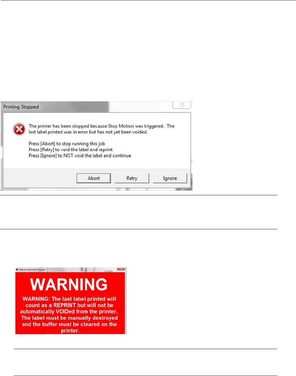
LVS-7510 Integrated System Operations Manual Version 20.2.X
LVS-7510 Integrated System Operations Manual Version 20.2.X Page 189 of 210
Appendix H: LVS-7510 Printronix Integrated System
The information in this appendix is intended for users of the LVS-7510 Printronix Integrated system used in
conjunction with the Printronix T8000r thermal barcode printer.
Printing Stopped Error Message
As the LVS-7510 is validating labels, a failed label will be overstruck and reprinted. If the label fails a second
time, the label will be overstruck and reprinted again. After three consecutive errors of the same type are
detected (except Foreground and Background errors), the printer stops printing labels and the “Printing
Stopped” message appears (see below).
Note: The text appearing in the “Printing Stopped” message can be edited in the “BeforeAbort.txt”
file. See the section further in this appendix entitled “Customizing the Printing Stopped and Manual
Intervention Required Messages” for instructions.
Options include:
Abort – Stops running the job. After clicking this button, Production mode users are prompted to login.
After logging in, the “Manual Intervention Required” message appears (see below). The user must be
granted the “Allow Abort” permission to allow the LVS-7510 to stop running the job.
“Manual Intervention Required” message
Note: The text appearing in the “Manual Intervention Required” message can be edited in the
“AfterAbort.txt” file. See the section entitled “Customizing Error Messages” for instructions.
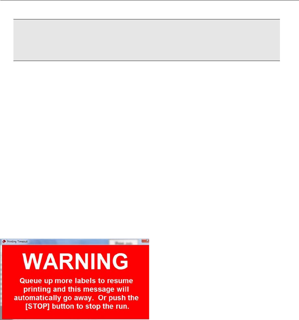
LVS-7510 Integrated System Operations Manual Version 20.2.X
LVS-7510 Integrated System Operations Manual Version 20.2.X Page 190 of 210
IMPORTANT: After aborting a print job, there may be print data remaining in the printer’s
memory buffer. If granted the “Allow Reset Printer” permission, a user can reset the printer to
accept new print data. For detailed instructions, refer to the “Reset the Printer” section further in
this appendix.
Ignore – Ignores the failed label and continues printing the next label in the job. After clicking this
button, Production mode users are prompted to log in. The user must be granted the “Allow Ignore”
permission to allow the LVS-7510 to ignore the failed label and continue printing the next label in the
job.
Retry – Voids the label and reprints the label. If the label fails, the “Printing Stopped” message appears.
There is no user permission associated with the “Retry” option.
Foreground and Background Errors
The three consecutive errors works differently for Foreground and Background errors. When a Foreground
and Background error occur on the same label, a single counter is set by the larger of the two errors.
Whichever of the Foreground or Background errors for that label repeat is larger will set/index the counter.
This means that if there are both a Foreground and a Background error(s) on the same label, the bigger
error (Foreground or Background) sets/indexes the counter. All errors are recorded but only the largest
Foreground or Background error affects the counter. The result is three Foreground errors are allowed (i.e.
will not stop the process) if a Background error accompanies any of the Foreground errors and the
Background error is larger than the corresponding label’s Foreground error. Additionally, three Background
errors are allowed (i.e. will not stop the process) if a Foreground error accompanies any of the Background
errors and the Foreground error is larger than the corresponding label’s Background error.
Printing Timeout Error
The following message appears when a printing timeout has occurred: “Queue up more labels to resume
printing and the message will automatically go away. Or, push the “Stop” button to stop the run.”
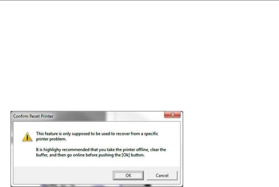
LVS-7510 Integrated System Operations Manual Version 20.2.X
LVS-7510 Integrated System Operations Manual Version 20.2.X Page 191 of 210
Reset the Printer
Sometimes the printer will stop printing for no apparent reason (like after aborting a print job) and there may
be print data remaining in the printer’s memory buffer. To reset the printer back to a state where it is ready to
accept new print data, follow the steps below. A user must be granted the “Allow Reset Printer” permission to
reset the printer.
1. Using the Printronix printer’s console buttons, take the printer offline, clear the printer’s buffer, and place
the printer back online.
2. The LVS-7510 software must be at the “Ready to run” screen.
3. Hold down the [Alt] keyboard button and click the “Print Job” button in the top, right corner of the “Ready
to run” screen. When the “Print Job” button is not active, ALT + R performs this function also.
4. Enter your login credentials. The “Confirm Reset Printer” message appears.
5. Click the “OK” button. The printer will reset and form feed a few label.
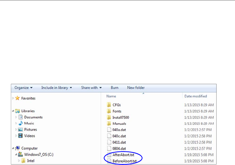
LVS-7510 Integrated System Operations Manual Version 20.2.X
LVS-7510 Integrated System Operations Manual Version 20.2.X Page 192 of 210
Customizing the “Printing Stopped” and “Manual Intervention
Required” Messages
To change the text appearing in the “Printing Stopped” and “Manual Intervention Required” error messages,
follow the steps below. Windows Administrator access is required.
1. Open Windows Explorer and access the following path:
C:\Program Files (x86)\ LVS 7510.
2. Copy the file(s) “AfterAbort.txt” or “BeforeAbort.txt” to your desktop (or another preferred location). The
“AfterAbort.txt” file contains the text appearing in the “Manual Intervention Required” message. The
“BeforeAbort.txt” file contains the text appearing in the “Printing Stopped” message.
3. Open the file in Notepad or another text editor program and make your changes. When changes are
complete, save and then close the file.
4. Copy the files (“AfterAbort.txt” and/or “BeforeAbort.txt”) back to C:\Program Files (x86)\LVS 7510.
5. Shut down and then restart the LVS-7510 software for the error message changes to appear.
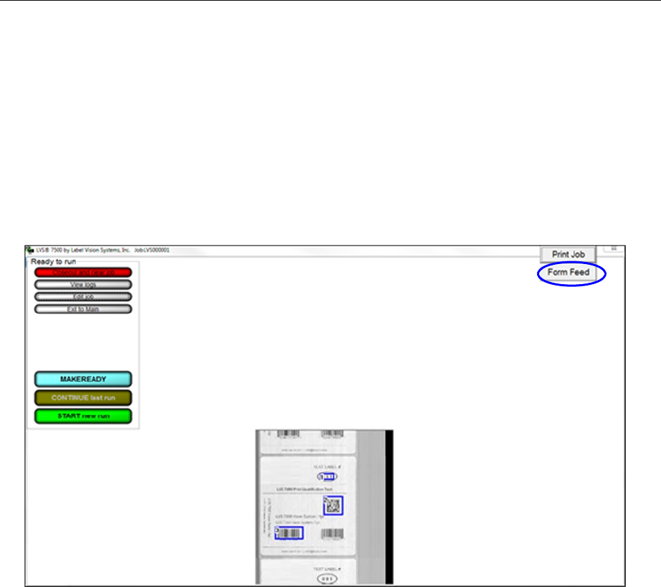
LVS-7510 Integrated System Operations Manual Version 20.2.X
LVS-7510 Integrated System Operations Manual Version 20.2.X Page 193 of 210
Form Feed Button
The “Form Feed” button advances all labels under the LVS-7510 readhead when printing is complete. ALT +
F also performs this function.
Labels fed from the printer after the “Form Feed” button is pressed are not inspected by the LVS-7510.
The ability to form feed labels is available only after the LVS-7510 stops inspection (by pressing the “Stop”
button). Form feeding labels is not available when a job is running or in MAKEREADY mode.
To form feed labels:
1. Click the “Stop” button to stop label inspection.
2. Click the “Form Feed” button. The LVS-7510 readhead advances all remaining labels.
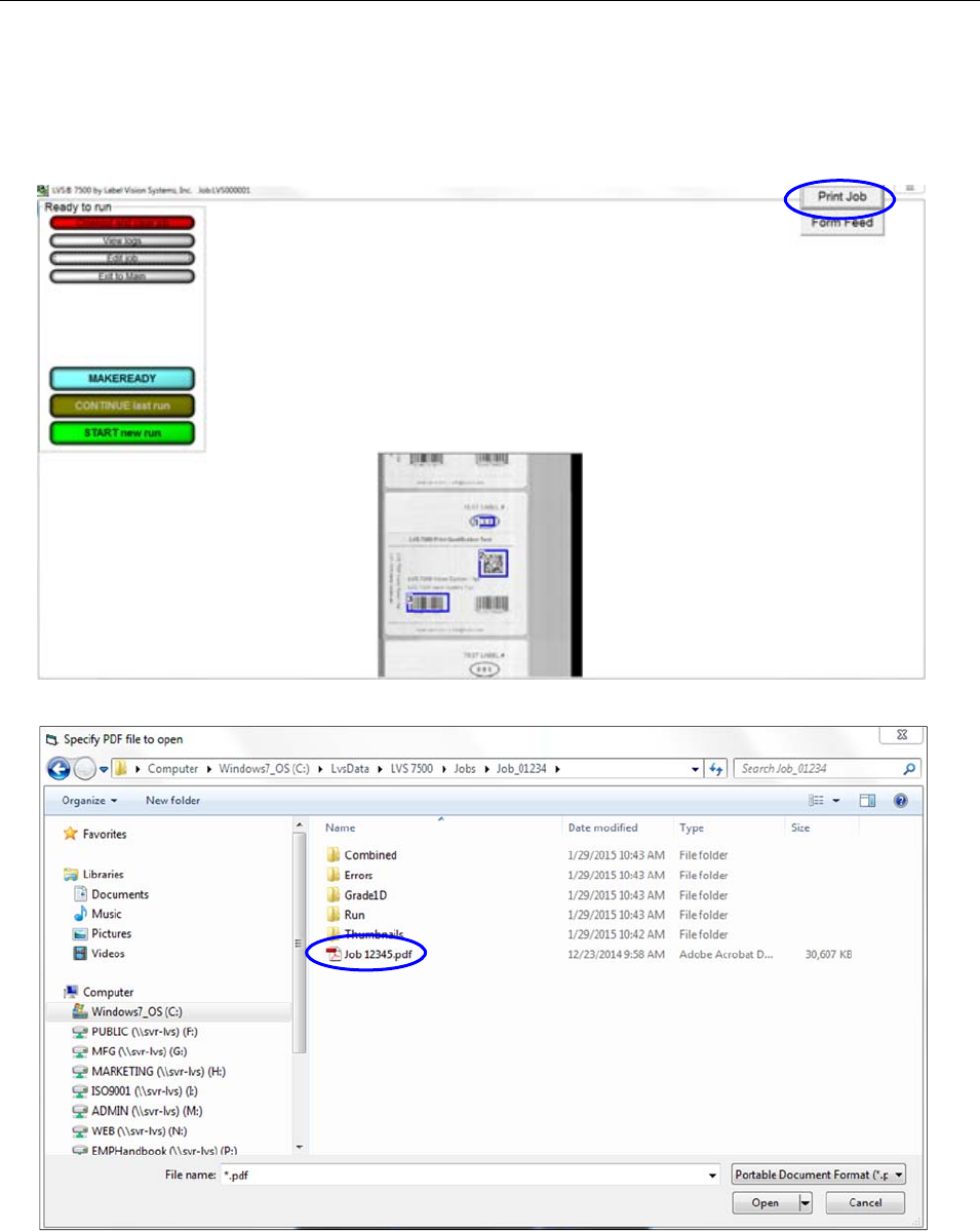
LVS-7510 Integrated System Operations Manual Version 20.2.X
LVS-7510 Integrated System Operations Manual Version 20.2.X Page 194 of 210
Appendix I: Print Job Button
The “Print Job” button allows you to view and print a PDF file of each job.
1. Click the “Print Job” button.
2. Select the job PDF file.
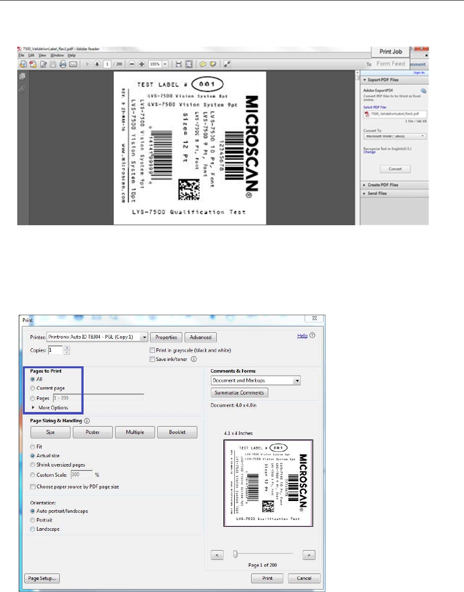
LVS-7510 Integrated System Operations Manual Version 20.2.X
LVS-7510 Integrated System Operations Manual Version 20.2.X Page 195 of 210
3. The job opens in Adobe Acrobat. From the menu bar, select File > Print.
4. You can print all the pages (labels) in the file or print selected pages. Select “All” to print all the pages in
the file, or enter the desired page numbers to print in the “Pages” field.
You can specify a group of non-sequential pages by separating them by commas (example: 4, 8, 19)
You can specify a sequential range of pages by putting a dash between them (example: entering 4-7
will print pages 4 through 7)
Your version of Adobe Acrobat may appear differently than the image below.
5. Label templates are created in Design mode. To ensure the labels print as designed in Production mode,
follow the steps below:
a. Click “Advanced.”
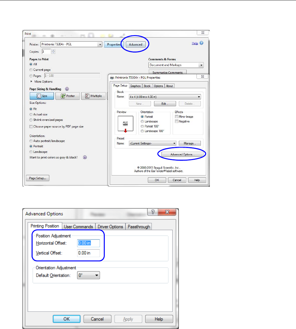
LVS-7510 Integrated System Operations Manual Version 20.2.X
LVS-7510 Integrated System Operations Manual Version 20.2.X Page 196 of 210
b. On the “Page Setup” tab, click “Advanced Options.”
c. Verify the “Horizontal Offset” and “Vertical Offset” settings in Production mode match the settings in
Design mode. Click “OK.”
6. Click “Ok” on the remaining windows. The labels begin printing. When complete, close Adobe Acrobat.
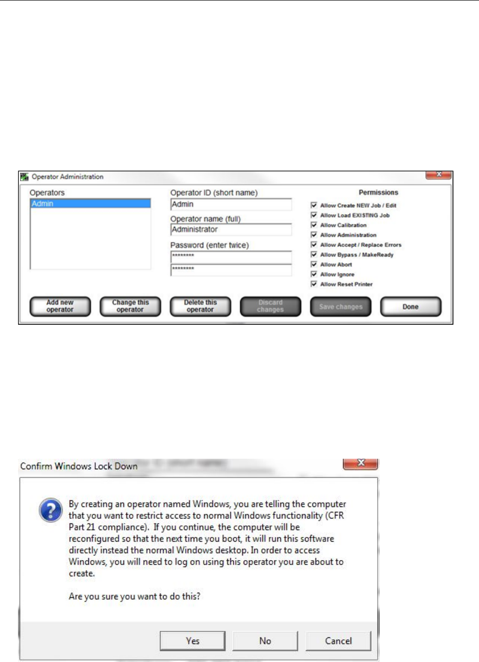
LVS-7510 Integrated System Operations Manual Version 20.2.X
LVS-7510 Integrated System Operations Manual Version 20.2.X Page 197 of 210
Appendix J: Windows® Lockdown
The Windows Lockdown feature locks down a Windows operating system, thus keeping the system secure
and preventing users from changing system settings. The Windows Lockdown feature supports Windows 7
Professional, and Windows 8.1 Professional and Windows 10 Professional,. Windows Vista is not supported.
To lockdown a Windows operating system, follow the steps below.
1. Open the LVS-7510 software and click login button. Enter Operator ID and password. NOTE: You must
log in as a user who has “Allow Administration” permissions
2. In the main menu click Administration and then click Operators; the Operator Administration window
appears.
3. Click the Add new operator button.
4. Type windows in the Operator ID (short name) field; letters are not case sensitive.
5. Type windows in the Operator name (full) field; letters are not case sensitive.
6. Type a user-defined password in the Password field. Do not lose or forget your password. Valid
passwords contain at least eight (8) characters; at least one (1) letter from A to Z; and at least one (1)
digit from 0 to 9.
7. The Allow Administration permission will automatically be selected.
8. Click the Save changes button.
9. The Confirm Windows Lock Down message appears (see below). Click Yes.
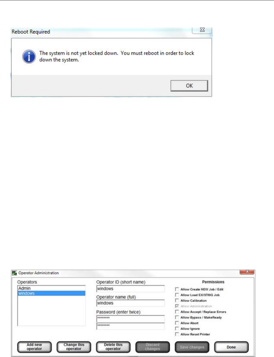
LVS-7510 Integrated System Operations Manual Version 20.2.X
LVS-7510 Integrated System Operations Manual Version 20.2.X Page 198 of 210
10. The Reboot Required message appears. Click OK.
11. Click the Done button.
12. Close the LVS-7510 software and then restart the computer.
13. The computer is in lockdown mode. The LVS-7510 software will automatically run and open to the
Welcome screen. All Windows® desktop functionality is disabled.
Shut Down the System
To shut down the system while Windows® is locked down:
1. Click the red X located in the top, right corner of the screen. The LVS-7510 software shuts down.
2. Press the computer’s power button to shut down the system.
Unlock
To unlock a Windows® operating system, follow the steps below:
1. Log out of the LVS-7510 software by selecting “Log on” and “Log out” on the main menu.
2. Click the “Log in” button and login with the Windows lock down account.
Enter Windows as your Operator ID.
Enter your user-defined password.
Click the Ok button.
3. In the main menu click Administration and then click Operators; the Operator Administration window
appears.
4. Select Windows from the Operator list and then click the Delete this operator button.
5. Click Yes when the Confirm Windows Lock Down message appears.
6. Click Ok when the Reboot Required message appears.
7. Follow any other onscreen prompts.

LVS-7510 Integrated System Operations Manual Version 20.2.X
LVS-7510 Integrated System Operations Manual Version 20.2.X Page 199 of 210
8. Close the LVS-7510 software by clicking the red X located in the top, right corner of the screen; the
screen turns blank.
9. Reboot the computer by pressing the computer’s power button to shut down the system. After the
system shuts down, press the computer’s power button to turn on the system. When prompted, enter
your desired Operator ID and Name to log on to the system.
10. The Windows® desktop is now unlocked and has returned to normal mode.

LVS-7510 Integrated System Operations Manual Version 20.2.X
LVS-7510 Integrated System Operations Manual Version 20.2.X Page 200 of 210
Appendix K: Using LVS-7510 PDF Comparator Function
Prior to using the PDF Comparator function, the 8-digit activation code for LVS-7510 must be entered. The
8-digit activation code is provided in printed and electronic form when ordering 98-9000079-01. To enter the
code, open the LVS-7510 home screen and click CTRL + A to open the code activation screen. After entry of
the 8-digit activation code for Feature Code 7014 (PDF Comparator), the LVS-7510 is ready to be used with
the ScanProof software. Contact Omron Microscan Technical Support if further assistance is needed:
Americas: Americas_support@microscan.com
Europe: EMEA_support@microscan.com
China: China_support@microscan.com
Other Asia-Pacific Areas: APAC_support@microscan.com
Installing ScanProof™ Software
Step 1 — Install Software
NOTE: Windows Administrator Access is mandatory to perform this installation. See the ArtProof-
ScanProof Installation Guide included on the USB drive shipped with this product (98-9000079-01).
1. Turn off User Access Control (UAC) settings in Windows. Click the Windows button. Type UAC in the
search field and click enter.
2. Select Control Panel, then select User Accounts Control Settings.
3. Select Never Notify and click OK.
4. Reboot the computer.
5. Copy the zip file (“ScanProof.zip”) from the supplied USB drive to the PC running LVS-7510 software.
6. Decompress the zip file and right click on the installation file, as described on page 29 of the ScanProof
Installation Guide.
7. While installing Microsoft .NET Framework 4.5, a message will appear requesting a reboot. Click Restart
Later.
See the ScanProof Installation Guide for details on the sequence of screens that are shown during a typical
installation and required installation steps.
Step 2 — Initial Configuration
To create a configuration setup for Omron Microscan LVS-7510, locate the “Microscan.ini” file on the USB
drive and copy it to: C:\Users\Public\ScanProof\Setups. NOTE: The ScanProof software must be installed
(see Step 1 above) before this path is valid. Follow the adjustment instructions in the ScanProof Software
User’s Manual.
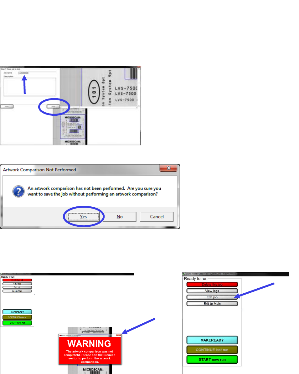
LVS-7510 Integrated System Operations Manual Version 20.2.X
LVS-7510 Integrated System Operations Manual Version 20.2.X Page 201 of 210
Launching ScanProof™ Software
Step 1 — Save Job
Create a NEW job in LVS software. In the Step 7 screen, enter a name for the new job. A description can
also be entered. Click the “>>>” button to save the job.
Click Yes when you see the dialog box shown at right:
Step 2 — Edit Job
The Ready to run screen will appear. Click the upper right button of the Warning dialog box to close it. Then
click Edit Job.
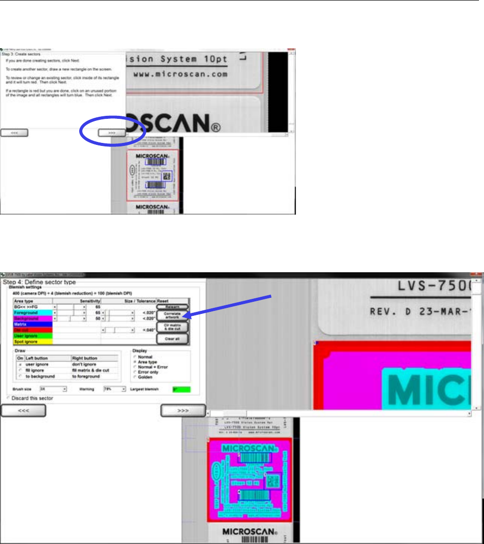
LVS-7510 Integrated System Operations Manual Version 20.2.X
LVS-7510 Integrated System Operations Manual Version 20.2.X Page 202 of 210
This will reopen the screen to create sectors. Click the “>>>” button to advance to the next screen.
Step 3 — Select the Master PDF
In the Step 4 screen, “Blemish settings”, click the Correlate artwork button.
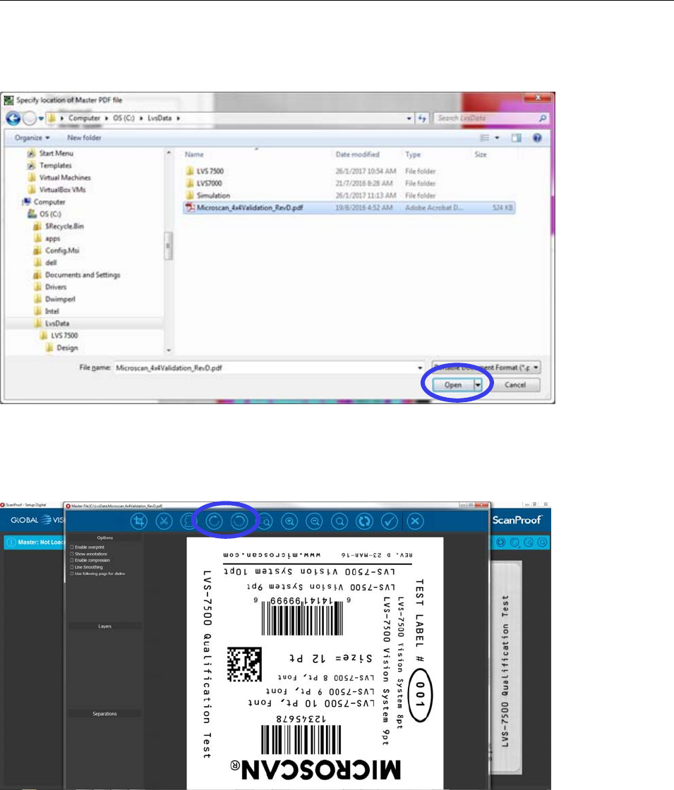
LVS-7510 Integrated System Operations Manual Version 20.2.X
LVS-7510 Integrated System Operations Manual Version 20.2.X Page 203 of 210
A browser window will open for you to select the Master PDF artwork file. Browse to the location of your
Master PDF, select the file, and click Open.
Step 4 — Open Master PDF in ScanProof
The LVS-7510 software becomes hidden. The ScanProof™ application will open and display the Master
PDF artwork. If needed, use the Rotate buttons to orient the image.
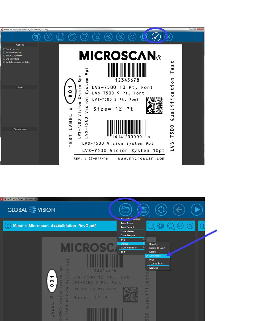
LVS-7510 Integrated System Operations Manual Version 20.2.X
LVS-7510 Integrated System Operations Manual Version 20.2.X Page 204 of 210
Click the Check Mark icon to confirm the Master PDF.
Step 5 — Run Comparison
Under the File Folder icon, select Setup, then Microscan.
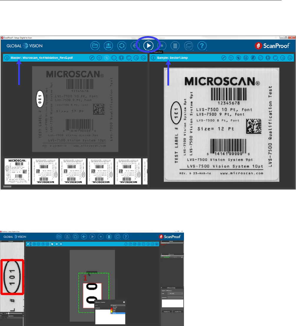
LVS-7510 Integrated System Operations Manual Version 20.2.X
LVS-7510 Integrated System Operations Manual Version 20.2.X Page 205 of 210
Click the Run icon to run the comparison between the Master PDF and the .BMP image of the sector created
earlier.
Step 6 — Review Differences
A list of differences between the labels, if any are found, will appear. You can review the details of each
difference and enter a classification.
There are 4 classification levels: Critical, Major, Minor, and Ignore.
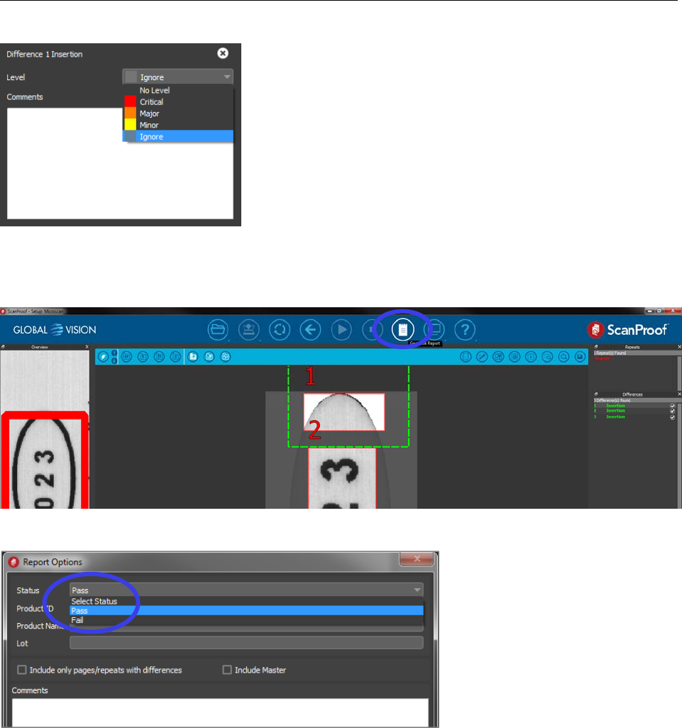
LVS-7510 Integrated System Operations Manual Version 20.2.X
LVS-7510 Integrated System Operations Manual Version 20.2.X Page 206 of 210
Step 7 — Set Status and Generate Report
Once you have completed the review, click the Generate Report icon.
In the open dialog box, select a status of PASS or FAIL for the comparison.
You may also complete additional fields such as Product ID, Product Name and Lot. Check the box to
include an image of the Master PDF in the report. Click Save.
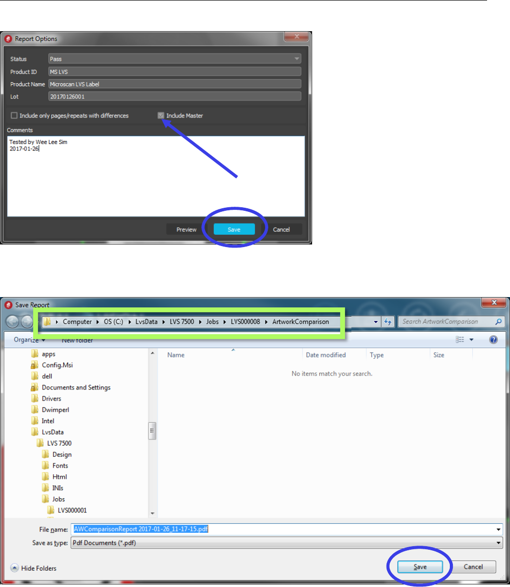
LVS-7510 Integrated System Operations Manual Version 20.2.X
LVS-7510 Integrated System Operations Manual Version 20.2.X Page 207 of 210
A browser window will open to select the folder location and file name of the report. The report should be
saved in the job folder: C:\LvsData\LVS 7500\Jobs\LVS000007A\ArtworkComparison. Keep the report with
the inspection job to ensure the LVS-7510 software is able to locate the report. Click Save to save the report.
See an example of a ScanProof report below (pages 1-2 of a 5-page report):
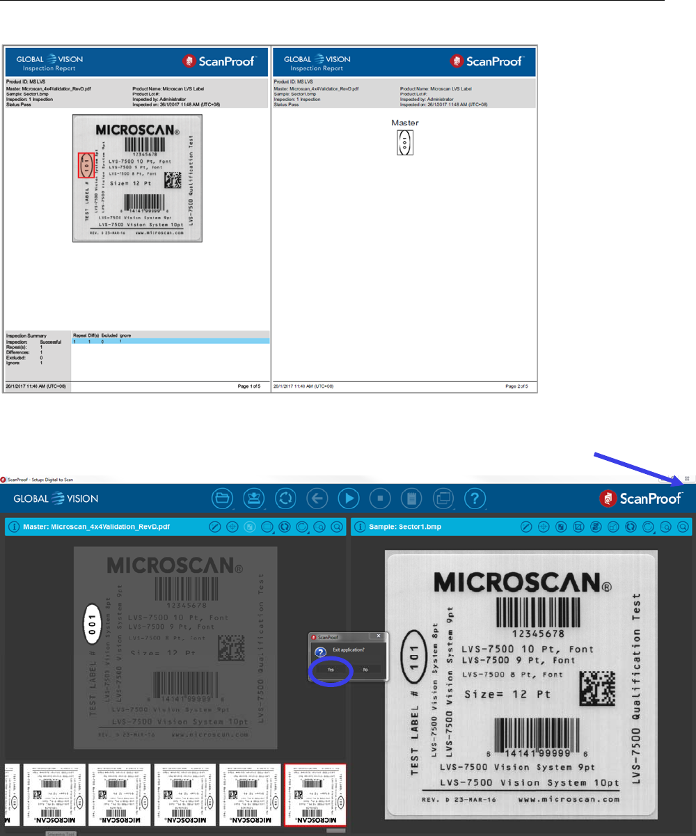
LVS-7510 Integrated System Operations Manual Version 20.2.X
LVS-7510 Integrated System Operations Manual Version 20.2.X Page 208 of 210
Step 8 — Return to LVS-7510 Software
Click the upper right button of the ScanProof application to close it. Click Yes to confirm.
LVS-7510 software and Blemish settings screen will reappear once ScanProof closes.
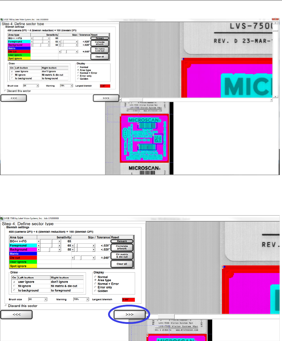
LVS-7510 Integrated System Operations Manual Version 20.2.X
LVS-7510 Integrated System Operations Manual Version 20.2.X Page 209 of 210
Step 9 — PASS or FAIL
LVS-7510 software will automatically access the ScanProof report saved into the job folder. If the report
status is set to PASS, you will continue to complete the Blemish Tool setup and save the job.
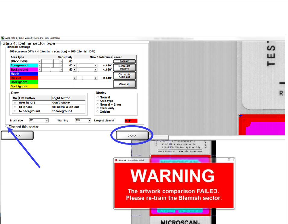
LVS-7510 Integrated System Operations Manual Version 20.2.X
LVS-7510 Integrated System Operations Manual Version 20.2.X Page 210 of 210
If the report status is set to FAIL, a warning message will appear to request creation of a new Blemish
sector. Select Discard this sector. Click the “>>>” button to continue to a screen to re-train the sector.
