Mimosa Networks 100-00001 Point to Multipoint Device User Manual 2 of 2
Mimosa Networks, Inc. Point to Multipoint Device Users Manual 2 of 2
Contents
- 1. Users Manual
- 2. Users Manual - 1 of 2
- 3. Users Manual - 2 of 2
Users Manual - 2 of 2

Mimosa Backhaul Help Content
Mimosa Backhaul Mounting & Grounding
Copyright © 2016 Mimosa Page 1
Mounting and Grounding the B5
This process ensures that the radio is securely attached to a mast/pole up to 90 mm (3.5 inches) in
This process ensures that the radio is securely attached to a mast/pole up to 90 mm (3.5 inches) in
diameter, and grounded to protect against electrical discharge.
diameter, and grounded to protect against electrical discharge.
Note that when operating in the U-NI-1 band (5150-5250 MHz), the FCC requires operators to adhere to
the following EIRP limit above certain elevations: “Maximum e.i.r.p. above 30 degrees measured from the
horizon ≤ 125 mW (21 dBm)”.
EIRP must be under 21 dBm at all elevations angles above 30 degrees. If operating in U-NII-1 band, the
installer has to take into account the elevation angle of each particular installation and radiation patterns
of the antenna used to determine the maximum allowable transmit power.
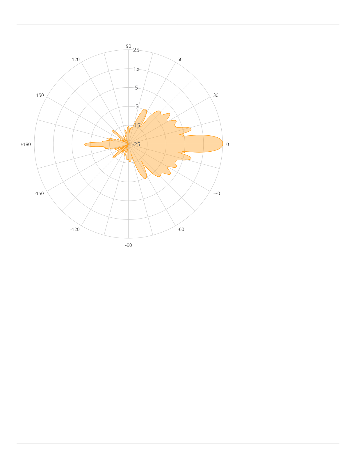
For example, consider the antenna pattern shown below of the B5 antenna, and the 25 dBi antenna used
for the B5c. If this antenna was installed at 5 degrees downtilt, maximum antenna gain should be noted in
the radiation pattern, at angles 5 + 30 = 35 degrees. In this case, it is -1 dBi. EIRP = transmit power +
antenna gain < 21 dBm. Thus transmit power should be limited to 21 dBm – antenna gain = 21 dBm – (-1
dBi) = 22 dBm.
The parabolic antenna pattern below represents both vertical and horizontal planes.
Mimosa Backhaul Help Content
Mimosa Backhaul Mounting & Grounding
Copyright © 2016 Mimosa Page 2
Follow these steps to mount and ground the B5 Radio.
Using a #4 Allen wrench (eight inches or longer recommended), attach the Bracket Assembly to the back of1.
the B5 with four provided M6 x 10mm SST Button Head Cap Screws.
Mimosa Backhaul Help Content
Mimosa Backhaul Mounting & Grounding
Copyright © 2016 Mimosa Page 3
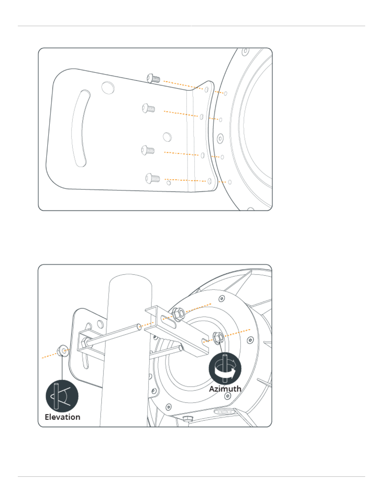
Remove the two nuts from the same side of the Pole Mount. Feed the bolts through the Bracket Assembly with2.
one bolt through the fixed hole, and the other bolt through the slotted arc. Thread the two nuts onto the bolts
on the outside of the Bracket Assembly, and then tighten loosely (some adjustment is required in a later step).
Slide the Pole Mount over the top of the pole as shown in the diagram, rotate the mount around the pole as3.
needed, and then tighten the bolts on the opposite side of the mount to secure. If the top of the pole is

Mimosa Backhaul Help Content
Mimosa Backhaul Mounting & Grounding
Copyright © 2016 Mimosa Page 4
obstructed or inaccessible, disassemble the other side of the Pole Mount and then reassemble it around the
pole.
Aim the radio using physical Elevation and Azimuth movements, then check and tighten each of the bolts until4.
secure.
Attach a 6 mm2 (10 AWG) ground wire with a maximum length of 1 m (3.3 feet) between the Bracket Assembly5.
of the B5 and a suitable grounding location on the tower or structure. The provided grounding screw is M5 x
6mm.
Related:
B5 Specifications - See specification sheet section entitled, "Physical" for additional mounting hardware details.
Hardware & Materials - Details about what materials are used in each provided part.