Mitutoyo Typewriter 99Mbe021A Users Manual *DP 1VRPage
2015-02-09
: Mitutoyo Mitutoyo-Mitutoyo-Typewriter-99Mbe021A-Users-Manual-557245 mitutoyo-mitutoyo-typewriter-99mbe021a-users-manual-557245 mitutoyo pdf
Open the PDF directly: View PDF ![]() .
.
Page Count: 63

MANUAL No. 99MBE021A
SERIES No. 264
Digimatic Mini-Processor
User's Manual
In order to obtain the best possible performance from the Mitutoyo
Digimatic Mini-Processor DP-1VR,
read this user’s manual thoroughly before operation.
After reading, retain it close at hand for future reference.
DP-1VR
i
THE MARKS USED IN USER'S MANUAL
The meaning of symbol mark and contents describe with each symbol mark used
in users manual is as follow.
Notice on Safety
In user's manual, to use exactly this unit, and to protect from yours and other
peoples damage and property, several chart expression. The expression and
meaning are as follows.
●Following expressions shown general notices, cautions and dangers, but not
limited.
Neglecting this expression, if you deal with this unit by incorrect way, it
will be imminent occurrence of human death or heavy injury.
Neglecting this expression, if you deal this unit by incorrect way, it will be
supposed to occur possibility of human death or heavy injury.
Neglecting this expression, if you deal with this unit by incorrect way, it
will be supposed to occur possibility of human damage and physical
damage.
ii
THE MARKS USED IN USER'S MANUAL
●The following marks show notice, exhibit of action/compulsion
This marks show that there is contents urge the notice (include danger,
warning. In the chart, concrete notice meaning is shown (left chart mean
electrical shock)
This mark express exhibited action. Concrete exhibited actions are drawn
in the charts or near the charts. (left chart means exhibit of disassemble)
This mark express the action under compulsion or direction. Concrete
directed actions are drawn in the charts or near the charts. (left chart
shows necessity of earth)

iii
Important
Notice
Reference
When any damages happen by the method not to depend on this
manual, our company does not have any responsibilities.
Contents of this manual may be changed without advance notice.
(c) Copyright Mitutoyo Corporation. All rights reserved.
THE MARKS USED IN USER'S MANUAL
About several kinds of notice.
Several kinds of "notice" which assist to obtain high reliable measured data
show in following words.
◆Notice indicates necessary information to achieve the purpose.
Do not neglect this direction.
◆If you do not follow this direction, there are the possibilities to loss
or difficult to maintain the performance and accuracy of this unit.
This word indicates especially emphasize or supplementary informa-
tion.
It shows that there are attentions for specified operation (limit of
memory, construction of equipment, information concerned with
special version of program. etc.)
This word indicates reference information concerned with operating
method and procedure described in this manual to apply for particu-
lar problem or details explanation of operation and function.
And if there are other reference informations, they may be shown the
reference portion

iv
NOTICE ON SAFETY (PLEASE READ SURELY)
To use safely, you should observe following.
◆This unit is intended to be used for a general equipment (measuring
equipment, or machine tool etc.) Do not use this unit for medical
machine, aerospace vehicle, train or atomic power etc. which miss
operation of this unit have possibility to injure the human body or
treated human life. When you intend to use for such purpose, please
inform to our company in advance.
◆If accidents happen such as smoke, curious smell or abnormal
operation, cut power and pullout AC adapter from consent, then
inform to service network. If you continue operation, it causes fire or
electric shock.
◆When you drop this unit and it is damaged, cut power and pullout AC
adapter from consent, then inform to service network. If you continue
operation, it causes fire or electric shock.
◆Do not repair or modify this unit by user. As it causes fire or electric
shock, do not implement absolutely.
◆When foreign object puts into this unit, cut power and pullout AC
adapter from consent, then inform to service network.
v
NOTICE ON SAFETY (PLEASE READ SURELY)
◆Please keep specified power source voltage. When this unit is used
with not specified power source voltage. it causes damage of inside,
fire or electric shock.
◆Please do not put this unit at the place opened to direct sunshine or
hot temperature. Inner temperature of this unit increases and causes
fire.
◆Do not put this unit close to wall. Inner temperature increases and
causes malfunction. And also please put this unit apart about 10 cm
from wall as you can pullout the cord of power source without moving
this unit.
REGARDING TO EC COMMAND CONFORMITY
◆This unit is conformed to following EC Command.
EMC Command EN61326-1997+A1:1998

vi
CONTENTS
The marks used in this user's manual ........................................................................... i
Notice on Safety (Please read thoroughly) ................................................................ iv
WARRANTY ............................................................................................................. vi
1. OUTLINE........................................................................................................ 1
1. Introduction ........................................................................................................... 1
2. Features .................................................................................................................. 1
2. SET UP .......................................................................................................... 3
1. Power supply ......................................................................................................... 3
1.1 Setting the battery ......................................................................................... 3
1.2 Connection of the AC adapter ....................................................................... 5
2. Set of recording paper............................................................................................ 6
3. Connection of the measuring tool .......................................................................... 7
4. Other connection.................................................................................................... 8
4.1 Attachment of strap....................................................................................... 8
4.2 Footswitch..................................................................................................... 9
4.3 RS-232C Cable • GO±NG judgement cable................................................. 9
4. PARAMETER ............................................................................................... 10
1. Parameter ............................................................................................................. 10
2. In the case of connecting caliper micrometer ...................................................... 10
3. In the case of printout of RS232C linearscale output .......................................... 12
4. Example of parameters setting ............................................................................ 15
4.1 DP-1 parameter setting procedure .............................................................. 15
5. SUMMARY OF FUNCTIONS ....................................................................... 19
1. Key functions....................................................................................................... 19
2. Function of each mode ........................................................................................ 20
3. Timer input function ............................................................................................ 21
6. OPERATION ................................................................................................ 22
1. Power ON/OFF .................................................................................................... 22
2. Basic Operation 1 ................................................................................................ 23
2.1 Data input, cancel, clear.............................................................................. 23

vii
CONTENTS
3. Basic operation 2 ................................................................................................. 25
3.1 Input of tolerance limit data ........................................................................ 25
3.2 Confirmation/renew of limit data ............................................................... 27
3.3 Release of limit data ................................................................................... 28
3.4 Data input, cancel, clear.............................................................................. 29
4. Mode 3 ................................................................................................................. 32
5. Print RS232C of counter...................................................................................... 34
6. OTHER NOTICES ........................................................................................ 36
7. MAINTENANCE ........................................................................................... 37
1. Clean printer head ................................................................................................ 37
2. Clean paper sensor ............................................................................................... 37
8. ERROR MESSAGE...................................................................................... 39
1. Alarms concerning electric power ....................................................................... 39
2. Other alarms ........................................................................................................ 40
9. CALCULATION METHOD ........................................................................... 42
1. Significant figure ................................................................................................. 42
2. Overflow and calculation tolerance ..................................................................... 43
3. Calculation tolerance detail ................................................................................. 44
4. Calculation formula ............................................................................................. 45
4.1 Calculation of Mode1, Mode2 .................................................................... 45
4.2 Calculation Mode3...................................................................................... 46
10. OUTPUT....................................................................................................... 47
1. Output of GO/±NG Judgment Result .................................................................. 47
2. Output in Accordance with RS-232C Format...................................................... 47
2.1 Communication Specifications ................................................................... 48
2.2 Data Format ................................................................................................ 48
2.3 Error Code .................................................................................................. 49
2.4 Data request command................................................................................ 49
11. TROUBLESHOOTING ................................................................................. 50
12. SPECIFICATIONS ....................................................................................... 52
SERVICE NETWORK .................................................................................. 54

- 1 -
OUTLINE
1
1. Introduction
DV-1VR is an exclusive piece of data processing equipment that records data from a
Mitutoyo digimatic tool so it can be statistically processed operation is easy and
statistical results can be obtained quickly.
2. Features
(1) Abundant statistical parameters:
Number of samples (N) • Maximum value (MAX) • Minimum value (MIN) •
Range (R) • Mean value (X) • Standard deviation (σ-n, σn-1) • Process capability
index (CP, CPK) • Number of defects (±NG) • Percent detective (P)
Limit data 5 types
(2) Preparation of histogram
(3) Preparation of a chart of displacement that expresses the time history of mea-
sured data D (Displacement).
(4) Several calculation functions necessary to prepare the X-R control chart.
(5) Timer input function.
(6) Data output function.
Output of measured data (RS-232C, TTL Level)
Output result of success or failure (+NG, GO, −NG)
It can be connected to Mitutoyo Instrument Network System (µNET System)
(7) Output of success or failure by LED.
(8) Power source system of AC adapter or four AA type Nickel Hydrogen batteries
(Ni-MH)/Alkali batteries (LR6)
(9) Standard equipment of 48 m recording paper.
OUTLINE
- 2 -
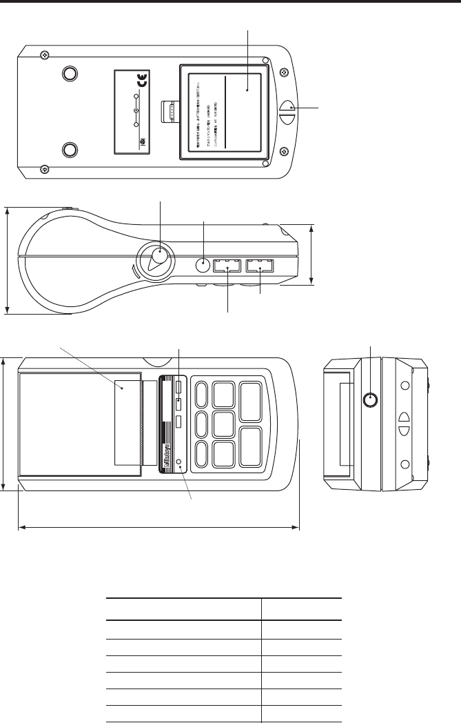
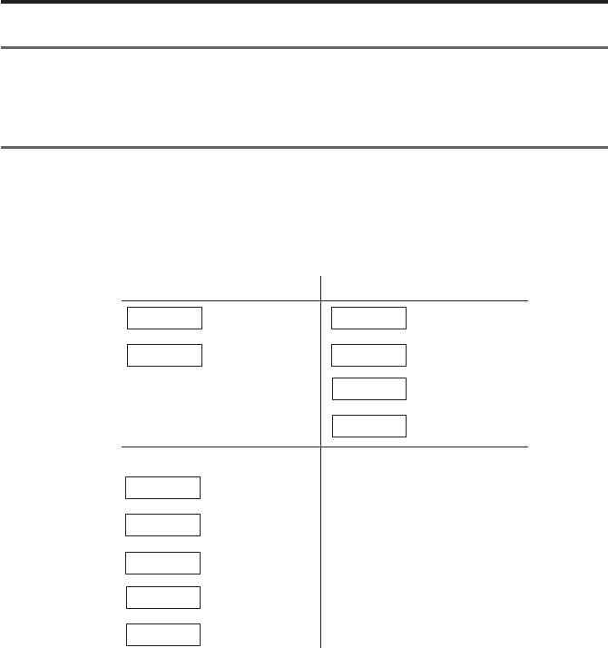
External view
Parts List
Parts name Quantity
DP-1VR (Main unit) 1
AC adapter 1
Recording paper 1
Strap 1
Quick reference 1
User’s manual 1
Must use the following types of battery
for battery operation.
Alkaline battery LR6
AA Ni-MH battery
+−
Mitutoyo Corporation
MADE IN JAPAN
Code No.
Model
Serial No.
Power
INPUT OUTPUT ADAPTER
OPEN
POWER
POWER
−
NG
PRINTER CL
CESTAT
FEED DATA
TOL.
LIMIT
GO
+
NG
DIGIMATIC MINI-PROCESSOR
EXT.P
75.2
43.9
94
201.1
Foot switch connector
GO/±NG LED
Adapter jack
Release lever
Strap attachment
Battery box
Output connector
Input connector
Power source LED
Recording paper cover/
Recording paper
- 3 -
SET UP
2
1. Power supply
●Power is supplied to this unit by the AC adapter or four AA type Nickel Hydrogen
batteries (Ni-Mh)/Alkali batteries (LR6)
●When the AC adapter is used while batteries installed, the power will be supplied
from the AC adapter (batteries are not included). The AC adapter cannot charge the
batteries, charge them with a dedicated battery charger, if necessary.
●When a voltage drop occurs when using the battery or AC adapter, the power
source LED will blink and show an abnormal condition.
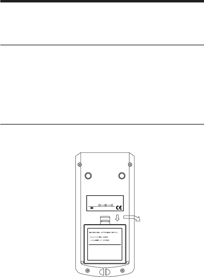
1.1 Setting the battery
Set the batteries. If using the AC adapter, refer to section 1.2
qq
qq
qOpen the battery box.
Must use the following types of battery
for battery operation.
Alkaline battery LR6
AA Ni-MH battery
+−
Mitutoyo Corporation
MADE IN JAPAN
Code No.
Model
Serial No.
Power
Push down the stopper of the battery box and pull forward.
- 4 -
SET UP
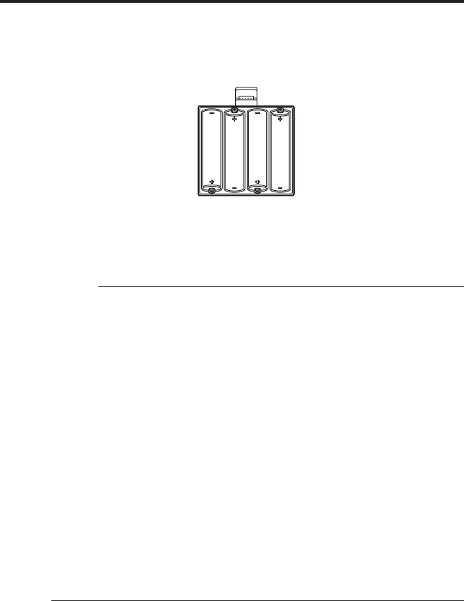
ww
ww
wSet the batteries.
Be sure to set correctly the poles of the size AA Alkali batteries (LR6) or Nickel
Hydrogen batteries (Ni -MH AA)
eClose the battery box by the inverse process of q firmly until you hear the
clicking sound.
IMPORTANT
◆Set the poles of batteries correctly.
◆Do not use different kinds of batteries.
◆Use either size AA Alkali batteries (LR6) or AA Nickel Hydrogen batteries
(Ni-MH AA)
◆Manganese batteries R6 cannot be used.
◆When Alkali batteries are used, printed letters may fade accordingly.
◆When Alkali batteries or Nickel Hydrogen batteries are used, print speed is
slower compared with the AC adapter.
◆In the case of using batteries, if the surface shows peeling or breaks on the pole
of the battery, it may cause poor contact and start-up. Please use batteries only
after you check there is no peeling or surface breaks on the poles of batteries.
◆If DP-1VR is not used for a long period, please remove the batteries from DP-
1VR. If the batteries remain connected to the DP-1VR for long time, fluid
leakage may damage the DP-1VR.
◆The operational temperature of the batteries must remain over 10°C. If the
temperature is less than 10°C, undesirable things, such as printed letters
become thin, etc., may occur.

- 5 -
SET UP
NOTE
◆DP-1VR has no charger function. If you need to charge the batteries, a
dedicated battery charger is needed.
◆Battery life is about 10,000 lines, (using 1,600 m Ah Ni-MH, and print large,
letter one time per 5 sec.)
◆Battery life varies drastically in accordance with environmental conditions.
1.2 Connection of the AC adapter
Connect the AC adapter to the DP-1VR.
Skip this page when using batteries.
POWER
POWER
−
NG
PRINTER CL
CESTAT
FEED DATA
TOL.
LIMIT
GO
+
NG
DIGIMATIC MINI-PROCESSOR
Insert firmly all the way.
◆The AC adapter specified by our company should be used.
100/115V 09EAA088
230V 09EAA088D
230V UK 09EAA088E
◆If the specified AC adapters are not used, print quality and life expectancy will
be reduced.

- 6 -
SET UP
2. Set of recording paper
q
OPEN
●Push the release lever downward
●Move the cover of recording paper upward, then open it.
w
●Peel tape fixing the edge of record paper, then set the recording paper with a little
bit of the paper pulled out.
●Set the core of the recording paper firmly in the holder. If the recording paper is
wrinkled, it can cause the paper to jam while printing, so be sure it is straight.
●Close the cover of the recording paper, pulling out the edge the recording paper a
little bit.
●Press the ‘power’ key to power ON and press the ‘FEED’ key, to send out the
recording paper about 100 mm.

- 7 -
SET UP
• Be careful to connect the connector correctly.
• Pull and put the connector in straight.
●When paper is set, be careful not to injure your hand by the paper cutter.
IMPORTANT
◆After setting the recording paper, be sure to press the ‘FEED’ key. This will
perform a self-alignment thereby reducing paper jamming.
◆When you open the recording paper cover, the printer head is exposed.
Immediately after printing, the printer head is hot. Do not touch to avoid being
burned.
◆DP-1VR recording paper has superior characteristic of conservation, tolerance
to chemicals and weather-proof. Please use the recording paper specified by
our company. (Part No. 09EAA082 10 roll pack)
◆Print quality is not guaranteed if the specified recording paper is not used.
◆Recording paper should be stored in a cool and dark place.
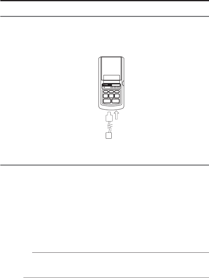
3. Connection of the measuring tool
Before connection, confirm that electric power to the digimatic measuring tool is OFF.
(1) Connection to the digimatic measuring tool.
Connect one connector of the connecting cable to DP-1VR input connector and the
other connector to the output connector of the digimatic measuring tool. Some con-
necting cables are different, depending on the type of measuring tool, please refer
to each user's manual.
OUTPUTINPUT
Connection of the input connector
- 8 -
SET UP
4. Other connection
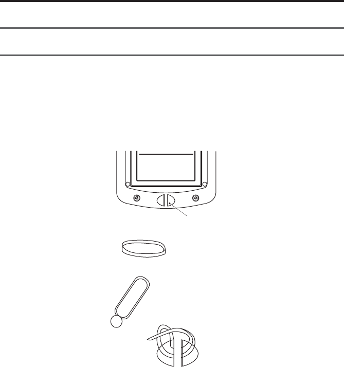
4.1 Attachment of the strap
Attach the strap to the DP-1VR as necessary
qTake the sling off the hook.
wPress the sling through the attachment point of the DP-1 as shown in the figure.
Must use the following types of battery
for battery operation.
Alkaline battery LR6
AA Ni-MH battery
Insert strap here
Sling
Hook
eHang the hook on the ring and pull out.
- 9 -
SET UP
4.2 Footswitch
Data can be input by a foot switch.
Connect to a foot switch connector, part No. 937179T (optional accessory)
POWER
POWER
−
NG
PRINTER CL
CESTAT
FEED DATA
TOL.
LIMIT
GO
+
NG
DIGIMATIC MINI-PROCESSOR
4.3 RS-232C Cable • GO
±
NG judgement cable
qRS-232C cable (part No. 09EAA084)
RS-232C output can be obtained from DP-1VR and used for printing RS-232C,
output of a linear scale counter. Connect the RS-232C cable to the DP-1VR output
connector.
wGO±NG judgment cable (part No. 965516)
The results of a judgment can be obtained from the DP-1VR. Connect it to output
connector of the DP-1VR.
NOTICE
The RS-232C cable and GO±NG judgment cable can not be used simultaneously.
Be sure to connect / disconnect the cables only when the power is OFF.

- 10 -
PARAMETER
3
1. Parameter
Parameter functions can customize the actions of the DP-IVR. Set up in accordance
with the purpose.
There are two kinds of parameter settings in accordance with connecting measuring
equipment to DP-1VR.
Select parameters in accordance with the measuring equipment used.
2. In the case of connecting calipers or micrometers
Parameters are established for digimatic interfaces such as calipers or micrometers
when connected to DP-1VR.
Start parameter setting mode by pushing the 'DATA' key and 'POWER' key simulta-
neously.
After parameter mode is started, parameters are printed in order. When you want to
change a setting, push the 'STAT' key and when you don't want to change a setting,
push the 'DATA' key; then the parameter will be set.
Next, a table of parameters is shown.

- 11 -
PARAMETER
Table 1 Parameter in DP-1 MODE
-rO red metIgnitteSnoitareporetnirPtluafeD
1-TEMARAP RAELCRE raelcretemaraP RAELCRETEMARAP RAELCONRETEMARAP raelctonoD sretemarap
2METSYS EDOM itluM/edom1-PDteS 1-PD edom 1-PD
3KROW EDOM /1EDOM/0EDOM 3EDOM/2EDOM 1EDOM/0EDOM 3EDOM/2EDOM 1edoM
4DUAB ETAR /0084/0042/0021 00291/0069 0084/0042/0021 00291/0069 0084
5YTIRAP ddO/nevE/enoN DDO/NEVE/NON NEVE
6ATAD HTGNEL 8/7 8/7 7
7TNIRP EZIS lamroN/egraL LAMRON/EGRAL EGRAL si2edomnehW lamronylnotes siezisgnitnirp elbaliava
8REWOP EVAS lamroN/evasrewoP LAMRON/EVAS lamroN
9TNIRP YTISNED kraD/lamroN KRAD/LAMRON lamroN
01 EDOMZB FFO/NOedomZB FFO/NO NO
11 EMIT TNIRP FFO/NOTNIRPEMIT FFO/NO
21 ATAD TAMROF TAMROFETAD DD/MM/YYYY YYY/DD/MMM YYY/MMM/DD
DD/MM/YYYY
31 ATAD GNITTESETADgnitnirpnehW.g.e ,2.naJ
0002 tamrofatadgnisu .21nidenifedgnittes 2/1/0002 0002/2/NAJ 0002/NAJ/2
dradnatSnapaJ emiT
41 EMIT GNITTESEMITdradnatSnapaJ emiT
51 TINU )hcni/mm(citamotuA retemilliM hcnI enoN marG edargitneC noT ecnuO
hcni/mmmm hcni
gC°
t.bL
citamotuA

- 12 -
PARAMETER
IMPORTANT
◆Set DP-1 for action mode.
NOTE
◆When entered into parameter input mode, limit data is cleared.
◆When parameters are cleared, they are set to default, except the date and time.
Date and time are reset to 2001/1/1, 0:0.
◆If a unit setting is selected, the unit set by this parameter is printed, regardless
of the unit of the input data. In this case the unit information of input data is
neglected.
3. Printout of a RS232C linearscale output
The following explains the parameter setting when the RS232C interface is attached
to the linear scale and printed by the DP-1VR.
To start parameter setting mode: Simultaneously press 'DATA' key and 'POWER' key.
After parameter mode is started, setting parameters are printed in order. When you
want to change a setting, press 'STAT' key and when you don't want to change the
setting, push 'DATA' key, then the parameter will be set.
Next, a table of parameters is shown.

- 13 -
PARAMETER
Table 2 Parameter in printing RS232CS output of counter
-rO red metIgnitteSnoitareporetnirPtluafeD
1-TEMARAP RAELCRE raelcretemaraP RAELCRETEMARAP RAELCONRETEMARAP raelctonoD sretemarap
2METSYS EDOM itluM/edom1-PDniteS PM edom1-PD
3KROW EDOM 1EDOM/0EDOM 1EDOM/0EDOM 1edoM
4DUAB ETAR /0084/0042/0021 00291/0069 0084/0042/0021 00291/0069 0084
5YTIRAP ddO/nevE/enoN DDO/NEVE/NON NEVE
6ATAD THGNEL 78/7 7
7TNIRP EZIS lamroN/egraL LAMRON/EGRAL egraL
8REWOP EVAS lamroN/evasrewoP LAMRON/EVAS lamroN
9TNIRP YTISNED kraD/lamroN KRAD/LAMRON lamroN
01 EDOMZB FFO/NOedomZB FFO/NO NO
11 EMIT TNIRP FFO/NOTNIRPEMIT FFO/NO
21 ATAD TAMROF TAMROFETAD DD/MM/YYYY YYYY/DD/MM YYYY/MM/DD
DD/MM/YYYY
31 ATAD GNITTESETADgnitnirpnehW.g.e ,2.naJ
0002 tamrofatadgnisu .21nidenifedgnittes 2/1/0002 0002/2/NAJ 0002/NAJ/2
dradnatSesenapaJ emiT
41 EMIT gnitteSEMITdradnatSesenapaJ emiT
51 TINU retemilliM hcnI enoN marG edargitneC noT ecnuO
mm hcni
gC°
t.bL
A/N
61 TUPNI SIXA tupniatadotsixateS ZYX /sixaY/sixaX sixaZ
71 SIXALUC atadfosixateS gnissecorp ZYX sixaX

- 14 -
PARAMETER
IMPORTANT
◆Set MP in action mode.
◆Even if you do not perform statistical calculations, data processing axis should
still be set.
NOTE
◆If the parameter is cleared, it is set to the default, except date and time.
◆If the parameter is cleared, date and time is reset to 2001/1/1, 0:0
◆Unit information is not sent out from the linear scale counter. So, if the unit is
not set, the unit is not printed in the data.
◆It’s possible to connect with K series counter only.
- 15 -
PARAMETER
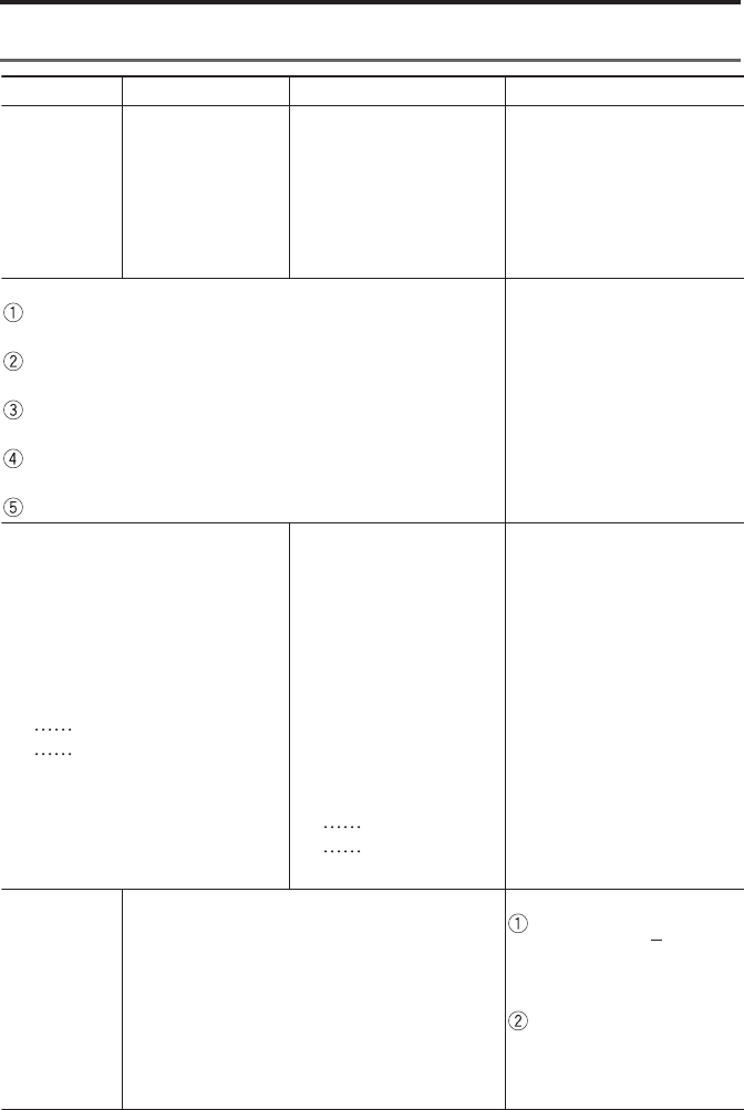
4. Example of parameter settings
Procedure to correctly set parameters is shown.
4.1 DP-1 parameter setting procedure
By entering the parameter mode, parameters can be set. To enter the parameter setting
mode when the electrical power is OFF, simultaneously press 'DATA' key and
'POWER' key. Then, the unit will enter the parameter mode.
In the parameter input mode, the following key operations can change setting details.
Parameter setting key Time setting
Setting change
Set
Date setting
STAT
DATA
STAT
DATA
STAT
DATA
Increase time
Minutes increase
Prints time
Sets time
PRINTER
CL
PRINTER
CL
CE
Year increase
Month increase
Day increase
Prints date
Sets Date
Additional settings
●Parameter clear
●Letter size
●Date
●Time
Examples of settings are shown on the following pages.

- 16 -
PARAMETER
PARAMETER SETUP MODE
SYSTEM MODE : DP-1
WORK MODE : MODE1
BAUDRATE : 4800
PARITY : EVEN
DATA LENGTH : 7
PRINT SIZE : LARGE
POWER SAVE : NORMAL
PRINT DENSITY : NORMAL
BUZZER MODE : ON
TIME PRINT : ON
DATE FORMAT : YYYY/MM/DD
DATE : 2000/ 1/ 1
TIME : 10:10
UNIT : AUTO
PUSH DATA : DATA FIX & GO
PUSH STAT : DATA CHANGE
PARAMETER NO CLEAR
PARAMETER CLEAR
PARAMETER CLEAR
SYSTEM MODE : DP-1
MODE : MODE1
BAUDRATE : 4800
PARITY : EVEN
DATA LENGTH : 7
PRINT SIZE : LARGE
PRINT SIZE : NORMAL
POWER SAVE : NORMAL
PRINT DENSITY : NORMAL
BUZZER : ON
TIME PRINT : ON
‘DATA’
+
‘POWER’
starting
STAT
DATA
DATA
DATA
DATA
DATA
DATA
STAT
DATA
DATA
DATA
DATA
Print the current setup in
parameter setting mode.
Print all parameters.
If selecting clear, a buzzer
sounds 4 times.
If mode 2 is chosen,
'NORMAL' is selected and
this item can not be input.
Letter size can be changed
by the 'STAT' key.
Set by the 'DATA' key
Key Print Comments
operation
Table 3 Example of parameter setting procedure

- 17 -
PARAMETER
DATA
CE
CL
PRINTER
STAT
DATA
CL
PRINTER
STAT
DATA
CE : DAY
CL : MONTH
PRINTER : YEAR
PUSH EACH KEY TO INCREMENT
DATE 2001/1/1
'CE' key increments date
Rotate 1~31
'CL' key increments month
Rotate 1~12
'PRINTER' key
increment change by rotating 00~20
'STAT' key print date setting is not printed by
'CE' 'CL' 'PRINTER' key operations
Finish setting by the 'DATA' key
YYYY/MM/DD : 2001/2/2
CL : MIN
PRINTER : HOUR
PUSH EACH KEY TO INCREMENT
TIME 11:11
'CL' key increments minute
Rotate 0~59
'PRINTER' key increments time
Rotate 0~23
'STAT' key print time setting is not printed by
'CL' 'PRINTER' keys
HH:MM:SS 11:11: 0
Finish setting by the 'DATA' key
HH:MM:SS 11:11: 0
UNIT : AUTO
Key Print Comments
operation
Change last 2 digits.
Seconds are fixed at 0.
Date and time is set and
written by the 'DATA' key.
In this case, second setting
is 0.

- 18 -
PARAMETER
DATA SYSTEM MODE : DP-1
WORK MODE : MODE1
BAUDRATE : 4800
PARITY : EVEN
DATA LENGTH : 7
PRINT SIZE : NORMAL
POWER SAVE : NORMAL
PRINT DENSITY : NORMAL
BUZZER : ON
TIME PRINT : ON
DATA FORMAT : YYY/MM/DD
DATE 2001/2/2
TIME 11:11
UNIT : AUTO
Key Print Comments
operation
IMPORTANT
◆Parameter input is memorized through the last operation. Do not stop the
operation if not completed.
◆Setting the date and time is written when the time input is set.
◆Appropriateness of data and time is not checked. Input normal value. Ex:
February 30th is incorrect.
◆Leap years and length of months are calculated automatically.
◆Clock is stopped during the parameter setting. When you set other parameters,
you should set the time too.
◆Set time in the 24-hour system.
NOTICE
◆After input is finished, it is transferred to the data input mode.
Printed summary of set
parameters

- 19 -
SUMMARY OF FUNCTIONS
4
1. Key functions
NOTICE
◆Sample size is determined by ‘STAT’ of subgroup 1
‘STAT’ of subgroup 2 and following are effective when data of sample 2 option
is input.
yeK
noitcnuF
0edoM2,1edoM
3edoM
gniruD puorgbuS gnirusaem
puorgbusretfA signirusaem etelpmoc
L
C
)yekraelc(
●
.atadderusaemylnosraelC
ylmrifhsup)niamersgnittes(
stimiltesotecnavdani
●
morftupni-eR
1.oN
●
ylnosraelC
atadderusaem
)niamersgnittes(
E
C
yeklecnac(
●
tsujatadderusaemseteleD
tupnierofeb
●
derusaemslecnaC
erofebtsujatad
tupni
●
-busseteleD
erofebtsujpuorg
tupnidehsinif
TIMIL.LO
T
)yektimil(
●
uoynehwyeksihtsserP
ehtmorftixerootniretne
reppufonoitarepognittes
.stimilrewoldna
●
foerusaemhsiniF
-uclacdnapuorgbus
tnirpdnaR,Xetal
tluser
TAT
S
)yektats(
●
noitcaoN
●
lacitsitatS
llahtiwedom
tuotnirpatad
detaluclac
dnatluser
ekam
margotsih
●
dnasetaluclaC
rab-Xehttuostnirp
nehtseulavRdna
ehtsetelpmoc
edomtnemerusaem
ehtsretnedna
edomnoitaluclac
●
-buSehtroF
esohwspuorg
sahtupniatad
,detelpmocneeb
ehtfonoitaluclac
sistimillortnoc
dnatuodeirrac
erastlusereht
.detnirp
DEE
F
)yekdeef(
●
tuodefsirapapgnidrocer,desserpnehW
ATA
D
)yekatad(
●
tnempiuqegnirusaemmorftupnisiataD
FFO/NORETNIR
P
)yekffo/noretnirp(
●
hctiwssihtybFFO/NOdenrutsiretnirP
REWO
P
)yekrewop(
●
rewopcirtceleehtfoFFO/NO
- 20 -
SUMMARY OF FUNCTION
2. Function of each mode
0edoM1edoM2edoM3edoM
●
noitcnuF
●
noitcnuF
●
noitcnuF
●
noitcnuF
tnirpoT
derusaem
dna,atad
egduj
.ecnarelot
derusaemtnirpoT
egduj,atad
mrofrep,ecnarelot
-aluclaclacitsitats
etarenegdna,snoit
.margotsih
hparg(trahc-DtnirpoT
ehtswohsylbisivtaht
derusaemfonoitairav
lacitsitatsmrofrep,)atad
dna,snoitaluclac
.margotsihetareneg
lliwti,atadgniretneyB
-Rawarddnaetaluclac
.trahclortnoc
)a gnittestimiL
,margotsihaeraperpdnastimiltnemgdujdroceruoyfI
hsup 'TIMIL.LOT' .erusaemotog,tonoduoyfI.yek
.oNatadtimiL.5fospuorgniderotsebnacatadtimiL
ehtgnihsupybdegnahcebnac 'TATS' yek
gnirusaemehtnoehttimilrewolroreppusserpxeoT
hsup,tnempiuqe 'ATAD' .yek
ehtnoylsuoenatlumiseulavtimilrehtonatcelesoT
ehthsup,tnempiuqegnirusaem 'ATAD' .yek
ehtgnihsupybteS 'TIMIL.LOT' .yek
S)atnemerusaempuorgbu
ybdetcudnocebnac
ehtgnihsup 'TIMIL.LOT'
yek
tupniebnac9999foXAM
.puorgbusa
puorgbusafoeziselpmaS
.01~2si
tnemerusaeM)b
ehtyB 'ATAD' atupniremit,yek
sdnammoctseuqerehtatad,ro
toof,tupniC232-SRehtmorf
fohctiwstuptuoataddnahctiws
dna,tnempiuqegnirusaem
.dedrocereraatadderusaem
/OG ±,
timilreppurevo
timilrewolrednu
tnemerusaeM)b
ehtyB 'ATAD' remit,yek
tseuqeratad,tupni
-SRehtmorfsdnammoc
derusaem,tupniC232
eratrahcDdnaatad
.dedrocer
segduj,emitemasehttA
noitcejerroecnatpecca
ehtsesserpxedna
tnemgdujgniwollof
.tuptuo
timilreppurevo
rewolrednu
timil
tnemerusaeM)b
ehtyB 'ATAD' remit,yek
tseuqeratad,tupni
-SRehtmorfsdnammoc
dnahctiwstoof,tupniC232
fohctiwstuptuoatad
,tnempiuqetnemerusaem
eraatadderusaemdna
.dedrocer
lacitsitatS)c
noitaluclac
ton
.detcudnoc
noitaluclaclacitsitatS)c
rofdetcudnocsinoitaluclaclacitsitatS
ehtybemittahtotpuatadderusaem 'TATS'
dnastluserdetaluclacsdrocerdna,yek
.margotsih
)c tnemeganamnoitaluclaC
hsuP 'TATS' enoyek
,R,Xehtneht,emit
puorgtahtfonoitaluclac
.detnirpsi
dnaemiteromenohsuP
eulavtimillortnochcae
puatadhtiwdetaluclacsi
.detnirpdnaemittahtot
▲
▼
왘
왗

- 21 -
SUMMARY OF FUNCTION
3. Timer input function
This function is used when you intend to take in data automatically from measuring
equipment in the same interval.
Press the PRINTER ON/OFF key, and at this state pushing the PRINTER ON/OFF
key enters the unit to this function, and the following pressed key can set the interval
time. When you finish this function, press the PRINTER ON/OFF key, while pressing
the ‘CL’ key.
NOTE
1. ‘CL’ ‘CE’ ‘ STAT’ keys fulfill their functions even if taking in data by the
interval timer.
2. When the interval timer is finished, if data is stored in the buffer, that data may
be printed.
3. During data input by the interval timer, if you intend to change the interval
time, finish this mode once, clear data and reset.
●Each key and interval times are as follows.
Key Interval time
STAT 0.25 sec
TOL.LIMIT 1 sec
CE 5 sec
CL 30 sec
DATA 1 sec
FEED 30 minute
PRINTER ON/OFF 60 minute
NOTE
◆Setting 0.25 sec, 1 sec, only statistical calculation results can be printed.
Measured data can not be printed. Also, when using 0.25 sec., the data buzzer
will not sound.

- 22 -
OPERATION
5
1. Power ON/OFF
Operation of power ON/OFF.
noitarepOyeKtnirP
NOrewoP REWOP
*RV1-PD* *1-EDOM*
2/2/0002ETAD 63:31EMIT
FFOrewoP REWOP dna.ces2nahteromsserP .esaeler
NOTE
◆To prevent mis-operation, power can be cut only when the 'POWER' key is
pressed more than 2 sec. Note that the power can not be cut if the pushing time
is short.
◆Contents of printout are a little different in the case of using extended letter
size from that of the standard letter size.

- 23 -
OPERATION
●Power ON
●Data input
Data can be input with the foot
switch interval timer or the
'DATA' key
●Data cancel
Cancel previous input data.
●Data all clear
Clear all input data
●Time printing
Print date and time
●Statistical calculation
Statistically calculates input data.
(This function is not available in
mode 0)
POWER
DATA
DATA
CE
CL
PRINTER ON/OFF
+ DATA
STAT
* DP-1VR *
* MODE 1 *
DATE 2000/ 2/ 2
TIME 13: 35
Take data from the measuring
tool and print.
1 12.23 mm
2 26.25 mm
* CANCEL *
* CLEAR *
DATE 2000/ 2/ 2
TIME 13:36
PART NO.
DATE 2000/ 2/ 2
TIME 13: 35
NAME:
*RESULT*
N56
MAX 81.26 mm
MIN 25.66 mm
R55.60 mm
X54.23 mm
σn12.5635 mm
σn-1 13.5897 mm
Function Operation Print
2. Basic Operation 1
Basic operations that do not have set limits are shown.
Similar operations are conducted in Mode0, Mode1, Mode2 also.
2.1 Data input, cancel, clear

- 24 -
OPERATION
IMPORTANT
◆Recording paper of DP-1 is superior to characteristics of conservation and
tolerance to chemicals, but it shares limits with other thermal papers. In the
case of long storage (more than 5 years), or if used for public documents, you
should make a photocopy.
◆If cutting fluid comes in contact with the recording paper, and those documents
will be stored for a long time, it is recommended to photocopy.
◆In the case of mode 0
Statistical calculation can not be conducted.
Maximum data that can be handled: 100000
◆In the case of mode 1
Maximum data that can be handled: 9999.
When 9999 data is input, statistical calculations are conducted automatically.
◆In the case of mode 2
Maximum data that can be handled: 9999.
When 9999 data is input, statistical calculations are conducted automatically.
Print type is same to mode1.
◆If the time print parameter is OFF, date and time will not be printed.

- 25 -
OPERATION
●Power ON
●Tolerance limit input mode
Tolerance limit input mode can
be entered the 'TOL.LIMIT' key.
Limit number can be changed
from 5 by the 'STAT' key.
●Input of limit data
After setting the upper and lower
limit for calipers, etc., press the
'DATA' key
Input order of the upper or lower
limit are performed in either order.
Data is recorded by the
'TOL.LIMIT' key.
POWER
TOL.LIMIT
STAT
DATA
DATA
TOL.LIMIT
Finish setting limits
* DP-1VR *
* MODE 1*
DATE 2000/ 2/ 2
TIME 13: 35
*LIMIT DATA 1*
LSL 12.56 mm
USL 25.89 mm
TOL 13.33 mm
*LIMIT MODE*
*LIMIT DATA 1*
*NO LIMIT DATA*
*LIMIT DATA 2*
LSL 12.56 mm
USL 25.89 mm
TOL 13.33 mm
LMT1 15.12 mm
LMT2 16.36 mm
*NEW LIMIT DATA*
*LIMIT DATA 2*
DATE 2000/ 2/ 2
TIME 13: 35
LSL 5.12 mm
USL 16.36 mm
TOL 1.19 mm
3. Basic operation 2
Operation procedures when tolerance limits are set is shown. Similar operations are
conducted in mode 0, mode 1 and mode 2.
3.1 Input of tolerance limit data
Operation to input limit data. Data is input through the connection of the measuring
equipment to the DP-1VR.

- 26 -
OPERATION
NOTE
◆To enter the tolerance limit input mode, q it is necessary that data is not input
just after power on, or w all data is cleared by operation of the 'CL' key.
◆In limit mode, limit data can changed by operation of the 'STAT' key. Maxi-
mum limit data of 5 is recorded. Reset limit data as necessary.
◆When limit data is input by selecting the number of limit data already set, new
data is saved and old data removed.
◆Limit data remains in memory even if the power is cut.
◆Just after power ON, limit data used at the time of power cut are selected.
◆When tolerance limit data is not necessary (when limit judgment is not
needed), select the limit number without limit data (refer to 3.2), or delete the
set limit data (refer to 3.3).

- 27 -
OPERATION
●Confirmation and reset of limit
data. If limit data is not input or it
is cleared by the 'CL' key, the
operation is possible.
Tolerance limit data is renewed by
'STAT'.
Press the 'TOL.LIMIT' key, for the
required tolerance limit data.
Renewed limit data is obtained.
TOL.LIMIT
STAT
STAT
STAT
TOL.LIMIT
LIMIT MODE*
*LIMIT DATA 2*
LSL 12.36 mm
USL 25.67 mm
TOL 13.31 mm
*LIMIT DATA 3*
LSL 12.56 mm
USL 25.89 mm
TOL 13.33 mm
*LIMIT DATA 4*
* NO LIMIT DATA *
*LIMIT DATA 5*
LSL 12.36 mm
USL 25.67 mm
TOL 13.31 mm
*NEW LIMIT DATA*
*LIMIT DATA 5*
DATE 2000/ 2/ 2
TIME 13: 35
LSL 12.36 mm
USL 25.67 mm
TOL 13.31 mm
3.2 Confirmation/reset of the limit data
The operation of confirming contents of 5 of tolerance limit data and resetting
tolerance limit data to use.

- 28 -
OPERATION
●Limit release
Press the 'CL' key to release
tolerance limit data. Limit data is
released.
TOL.LIMIT
CL
*LIMIT DATA 1*
LSL 12.36 mm
USL 25.67 mm
TOL 13.31 mm
*LIMIT CLEARD*
DATE 2000/ 2/ 2
TIME 13: 35
*LIMIT DATA 1*
*NO LIMIT DATA*
3.3 Release of the limit data
Operation to release the tolerance limit data. It is conducted when the limit data is not
necessary.
- 29 -
OPERATION
Function Operation Print
●Power ON
●Time print
●Data cancel
Prior input is canceled.
●Data input
All input data is cleared.
●Data input
Limit judgment is conducted for
the input data, displayed (LED)
and printed.
POWER
PRINTER ON/OFF +
DATA
CE
CL
DATA
DATA
DATA
* DP-1VR *
* MODE 1*
DATE 2000/ 2/ 2
TIME 13: 35
*LIMIT DATA 1*
LSL 12.36 mm
USL 25.67 mm
TOL 13.31 mm
DATE 2000/ 2/ 2
TIME 13: 35
* CANCEL *
* CLEAR *
H1 12.00 mm
2 26.25 mm
G3 32.56 mm
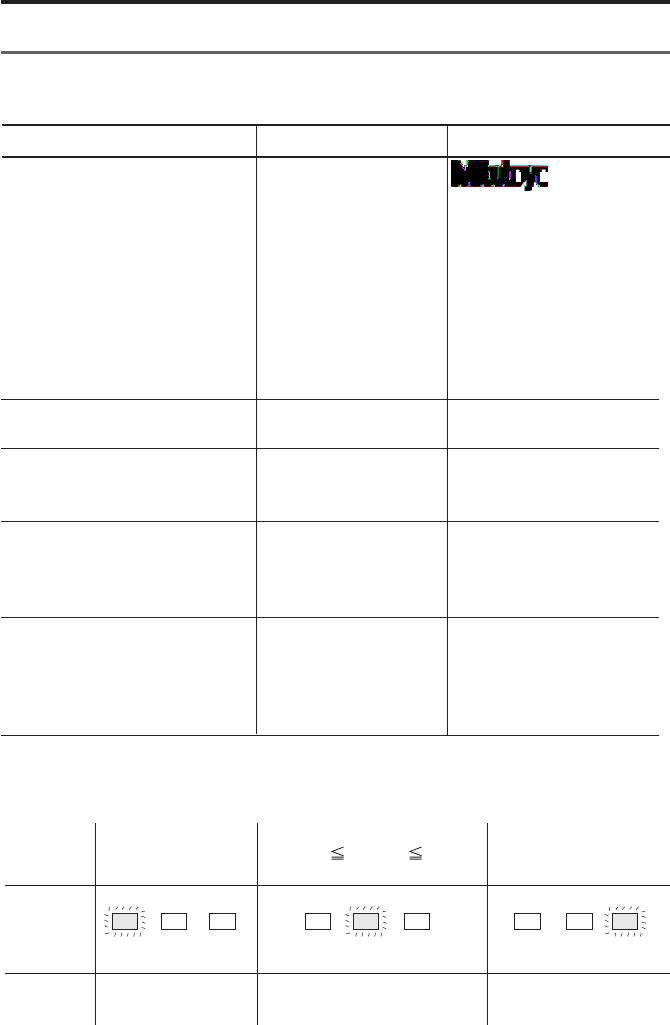
Input data, and relationship of display (LED) and print.
3.4 Data input, cancel, clear
Table 2 DP1 mode1, operation example 2
Input
Print
Input
data
Input
data
Input
data
Lower
limit
value
Lower
limit
value
Upper
limit
value
Upper
limit
value
−NG GO +NG −NG GO +NG −NG GO +NG
왖왔
쏝쏝
Display
(LED)

- 30 -
OPERATION
PART NO.
DATE 2000/ 2/ 2
TIME 13: 35
NAME
*RESULT*
N56
MAX 81.26 mm
MIN 25.66 mm
R55.60 mm
X54.23 mm
σn12.5635 mm
σn-1 13.5897 mm
−NG 2
+NG 4
P18.56%
Cp 0.45670
Cpk 0.30000
*HISTOGRAM*
LSL 12.36 mm
USL 25.67 mm
TOL 13.31 mm
DIV 10
−NG 2| □
LSL | N N N N N N
N N N
A2|□
B4|□□
C5|□□
D8|□□□□
E9|□□□□
F 11| □□□□□□
G4|□□
H9|□□□□
I5|□□
J4|□□
USL | N N N N N N
Statistical calculation
●Statistical calculations are
conducted, when 9999 or more
data is input.
Function Operation Print
STAT
Input data

- 31 -
OPERATION
IMPORTANT
◆DP-1 recording paper has superior characteristics of conservation and tolerance
to chemicals, but it shares limits with other thermal papers. In the case of long
storage (more than 5 years), or if used for public documents, you should make
photocopy.
◆If cutting fluid comes in contact with the recording paper, and those papers are
necessary to be stored a long time, it is recommended to store after photocopy-
ing.
◆In the case of mode 0
Statistical calculation cannot be performed.
Maximum data that can be handled: 100000
◆In the case of mode 1
Maximum data that can be handled: 9999.
When 9999 data is input, statistical calculations are performed automatically.
◆In the case of mode 2
Maximum data that can be handled: 9999.
When 9999 is input, statistical calculations are performed automatically.
Printing format of the data will be a D chart (analogical, volume changing
print)
◆If the time printing parameter is OFF, date and time will not be printed.
Function Operation Print
N N N
+NG 4| □□
□ = 2
A12.3600p
B13.6910p
C15.0220p
D16.3530p
E17.6840p
F19.0150p
G20.3460p
H21.6770p
I23.0080p
J24.3390p
25.6700p

- 32 -
OPERATION
Power ON
Initiate measurement of a sub-
group
Transfer a subgroup to measuring
mode.
Data receiving
(Subgroup measure mode)
Data cancel
Cancels prior input data.
('CL' key pressed during
measurement of a subgroup)
Subgroup data is all cleared.
Data in subgroup is all cleared,
and are measured again from No.1
data.
('CL' key pressed during
measurement of subgroups)
Time printing
Finish measurement of subgroup
and calculate X-R of subgroup.
(Normal sub-group measure mode
is finished)
Stop measurement of subgroup, and
release subgroup measure mode.
(Subgroup measure mode forced
finish)
POWER
TOL.LIMIT
DATA
DATA
DATA
CE
CL
PRINTER ON/OFF +
DATA
STAT
TOL.LIMIT
* DP-1VR *
* MODE 3*
DATE 2000/ 2/ 2
TIME 13: 35
SUB GR. NO.1
Print data received in from
measuring equipment.
1 12.00 mm
2 26.25 mm
3 32.56 mm
* CANCEL *
* CLEAR SUB DATA*
DATE 2000/ 2/ 2
TIME 13: 35
X0.92335 mm
R2.77568 mm
PART NO.
DATE 2000/ 2/ 2
TIME 13: 35
NAME
* EXIT SUB GR. *
Function Operation Print
4. Mode 3
Example mode3 operation

- 33 -
OPERATION
SUB GR. 2
Input data from measuring
equipment.
1 12.00 mm
2 26.25 mm
3 32.56 mm
X 0.92335 mm
R 2.77568 mm
PART NO.
DATE 2000/ 2/ 2
TIME 13: 35
NAME
*CONTROL LIMIT*
DATE 2000/ 2/ 2
TIME 13: 35
NO.OF SUB GR.
5
SAMPLE SIZE
8
X 4.1999 mm
X-UCL 6.9057 mm
X-LCL 1.4970 mm
R 2.6458 mm
R-UCL 6.8082 mm
R-LCL 6.8082 mm
DATE 2000/ 2/ 2
TIME 13: 35
*CLEAR SUB GR.*
*CLEAR ALL DATA*
TOL.LIMIT
DATA
DATA
DATA
STAT
STAT
PRINTER ON/OFF +
DATA
CE
CL
Function Operation Print
Measure next subgroup
Data input
Finish measurement of subgroup
and calculate X-R of subgroup
Calculation of control limits is
carried out from all the sub-group
data which has been input, and the
result is printed.
Time stamp
Cancels prior subgroup data. 'CE'
key is pressed after finishing
measurement of subgroup.
Clears measured data
'CL' key is pressed after finishing
measurement of subgroup.

- 34 -
OPERATION
POWER
PRINTER ON/OFF +
DATA
CE
CL
DATA
DATA
DATA
STAT
* DP-1VR *
* MODE 1*
DATE 2000/ 2/ 2
TIME 13: 35
*LIMIT DATA 1*
LSL 12.365
USL 25.675
TOL 13.310
DATE 2000/ 2/ 2
TIME 13: 35
* CANCEL *
* CLEAR *
H 1 X 12.000
Y 23.565
2 X 24.254
Y 23.896
G 3 X 32.566
Y 23.896
*RESULT*
PART NO.
DATE 2000/ 2/ 2
TIME 13: 35
NAME
N56
MAX 81.26
MIN 25.66
Function Operation Print
5. Print RS232C of counter
●Power ON
If parameter time stamp is 'OFF',
data and time are not printed.
●Time stamp
●Data cancel
Prior data input is canceled.
●Data all clear
All input data is cleared.
●Data input
Limit judgment is conducted for
input data and displayed (LED) and
printed.
Meanings of the symbols are as
follows.
H: DATA l Lower limit
: Lower limit m DATA m Upper
limit
G:Upper limit l DATA
DATA : Input data
Statistical calculation
●Statistical calculations are
started automatically where the
9999th data is input.

- 35 -
OPERATION
R55.60
X54.23
σn12.5635
σn-1 13.5897
−NG 2
+NG 4
P18.56%
Cp 0.45670
Cpk 0.30000
*HISTOGRAM*
LSL 12.36
USL 25.67
TOL 13.31
DIV 10
−NG 2| □
LSL | N N N N N N
N N N
A2|□
B4|□□
C5|□□
D8|□□□□
E9|□□□□
F 11| □□□□□□
G4|□□
H9|□□□□
I5|□□
J4|□□
USL | N N N N N N
N N N
+NG 4| □□
□ = 2
A12.3600p
B13.6910p
C15.0220p
D16.3530p
E17.6840p
F19.0150p
G20.3460p
H21.6770p
I23.0080p
J24.3390p
25.6700p
Function Operation Print

- 36 -
6
OTHER NOTES
In order to ensure data reliability of the SDP interface, DP-1VR reads the data twice.
Some models (KC counter with code out unit No. 09CAA462 etc.) are incapable of
performing the above data checking routine.
For those models, you must perform the following procedures by changing the
interface mode.
Interface mode is interchangeable with the former products (DP-1HS) by setting it for
COMPATIBLE.
Operation Printout
CE + POWER * DP-1VR *
SELECT SDPINTERFACE
PUSH STAT: MODE CHANGE
PUSH DATA: MODE FIX
INTERFACE: ADVANCED
STAT INTERFACE: COMPATIBLE
DATA Changing to data input mode
STAT: To change modes
DATA: To set the mode and to end the operation

- 37 -
7
Daily maintenance of DP-1VR
1. Clean printer head
When dust collects on the printer head, print quality is adversely affected, and
sometimes printing is impossible due to damage to the printer head. It is recom-
mended cleaning the printer head periodically.
Cleaning method:
After opening the printer cover the printer head can be seen. Rub the printer head
with a cotton swab soaked in a little alcohol. After that, wipe off the remaining
alcohol lightly with a dry cotton swab until dry.
2. Clean paper sensor
If the paper sensor becomes dirty, detection of the record paper is impossible and
normal operation can not be conducted. It is recommended to clean the paper sensor
portion periodically.
Cleaning method:
After opening the printer cover the printer sensor can be seen. Rub the printer sensor
with a cotton swab soaked in a little alcohol. After that, wipe off the remaining
alcohol lightly with a dry cotton swab until completely dry.
◆Just after finishing printing, do not clean. Printer head is hot; you may burn
your hand. Also, that heat may set the alcohol on fire.
◆Alcohol left on the head should be dried completely, since there is a possibility
it could ignite.
◆Handle the alcohol carefully.
◆Do not use thinners, benzene etc., only use alcohol.
MAINTENANCE

- 38 -
MAINTENANCE
Printer head
Paper sensor
Paper cutter

- 39 -
ERROR MESSAGE
8
1. Alarms concerning electric power
Table 1 Power related alarms
NOTICE
◆If the power goes off, data that was not saved is lost. Be sure to save all data
before removing the AC adapter from the DP-1VR during operation, even if
the DP-1VR is not being operated by the AC adapter.
◆Using batteries under 10°C may shorten battery life expectancy. If the
operating temperature is under 10°C, use the AC adapter.
noitidnoC egatloV noitceted
hsalfDELrewoP FFOdnaNO nretap
ataD tupni esaeleR noitidnoc
hgihyllamronbA egatlov nahterom V0.01 ces6.0,noces6.0 taeperffo elbissopmIniaganorewoP
lamroNV5.4~0.01nosyawlAelbissoP
;egatlovwolylthgilS noituac egatlovtahtesacehtnI yrettabehtspord .decudersiyticapac
V2.4~V5.4ces3.0,FFOces5.1 NO ces3.0,FFOces3.0 taeperNO
elbissoPfirevoceR snruteregatlov lamronot .noiger
egatlovwolyllamronbA egatlovtahtesacehtnI semocebdnawolsi .elbissopmi
V2.4nahtsseLces6.0,NOces6.0 taeperFFO elbissopmIniaganorewoP

- 40 -
ERROR MESSAGE
2. Other alarms
Table Error alarm of DP-1VR
fodniK mrala motpmySesuacelbissoPseidemeR
●
metsySrorre
●
rewopretfatsuJ lla,no sDEL hsalf
dnaffodnano .sdnuosrezzub
●
fororrelataF .derrucco1-PD
●
gnitarepO ootsierutarepmet .wolootrohgih
●
fI.niagapurewopotyrT ruomrofni,sruccoerelbuort ecivresroeciffotseraen .krowten
●
C°54~C°0neewtebesU
●
wolfrevO *WOLFREVO *
●
.detnirpsi
●
dnoyebsitI gnitaluclacelbissop .aera
●
'ybatadraelC LC yek'
.noitarepo
●
repapoN
●
DEL fo −GN ,
+GN dnanosehsalf
.ffo
●
enilderA ehtnosraeppa .repapdrocer
●
gnidroceroN .repap
●
repapgnidrocerecalpeR
●
neporevoC )pudaeH(
●
DEL fo −GN ,
+GN dnanosehsalf
.ffo
●
forevoC sirepapgnidrocer .nepo
●
revocesolC
●
tnemerusaeM sitnempiuqe .detcennocton
*EGAGON *
●
.detnirpsi
●
silootgnirusaeM .detcennocton
●
elbacgnitcennoC .nekorbsi
●
tcatnoclamronbA elbacgnitcennocni
●
lootgnirusaemtcennoC tnempiuqe
●
elbacgnitcennocegnahC
●
gnitcennocehtmrifnoC .elbacgnitcennocfonoitrop
●
tcerroctoN tamrof
*TAMROF RORRE *
●
tupnifotamroF .tnereffidsiatad
●
.elbacgnitcennocegnahC
●
gnitcennocehtmrifnoC .elbacfonoitrop
●
tnereffiD
tinu
*RORRETINU *
●
atadtupnifotinU .tnereffidsi
●
fotinunehwdetnirpsitI laitinimorftnereffidsiatad emasfoatadtupnI.atadtupni .atadtupnilaitinisatinu
●
-elottesmorftinutnereffiD tupnI.tupnisiatadtimilecnar .atadtimilsatinuemasfoatad

- 41 -
ERROR MESSAGE
fodniK mrala motpmySesuacelbissoPseidemeR
nirorrE tnioplamiced *RORRETNIOP *tnioplamiceD tupnifonoitisop .tnereffidsiatad
●
lamicedehtnehwdetnirpsitI morftnereffidsinoitisoptniop lamicedehT.atadtupnilaitini emasehtebdluohsnoitisoptniop .atadlaitiniehtsa
●
tnioplamicedtnereffiD siatadtimiltesmorfnoitisop emasehtfoatadtupnI.tupni timilsanoitisoptnioplamiced .atad
●
fonoituaC wolfrevo
●
rofspeebowT tupniatadhcae
●
wolfrevootraeN
●
dna,tnemerusaemhsiniF .noitaluclaclacitsitatstcudnoc ehtgnisuatadraelc,tahtretfA
'LC .yek'

- 42 -
CALCULATION METHOD
9
1. Significant figure
Significant figures of calculation are as follows.
When significant figures (figures after the decimal point) of input data are A, signifi-
cant figures are displayed.
Significant Figure
Displayed
Sign Meaning significant figure Error
(figure after the
decimal point)
DATA Input data A —
NData count 0 —
MAX Maximum value A —
MIN Minimum value A —
RRange A —
XMean A+2Last figure±1
σnStandard deviation A+2Last figure±1
σn-1 Standard deviation A+2Last figure±1
PPercent defective 3 (**.***%) Last figure±1
CPProcess capability index 3 Last figure±1
CPK Process capability parameter 3 Last figure±1
LSL Lower limit value A Last figure±1
USL Upper limit value A Last figure±1
DIV Histogram division number 10 division fix —
Histogram region express A+2Last figure±1
XCenter (X control) A+2Last figure±1
X-UCL Upper control limit (X control) A+2Last figure±1
X-LCL Lower control limit (X control) A+2Last figure±1
RCenter (R control) A+2Last figure±1
R-UCL Upper control limit (R control) A+2Last figure±1
R-LCL Lower control limit (R control) A+2Last figure±1
IMPORTANT
Range to apply calculation error is revealed in the calculation error detail.
- 43 -
CALCULATION METHOD
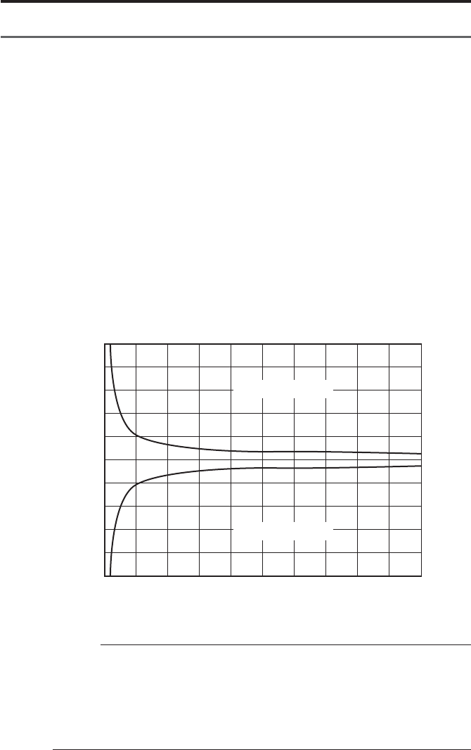
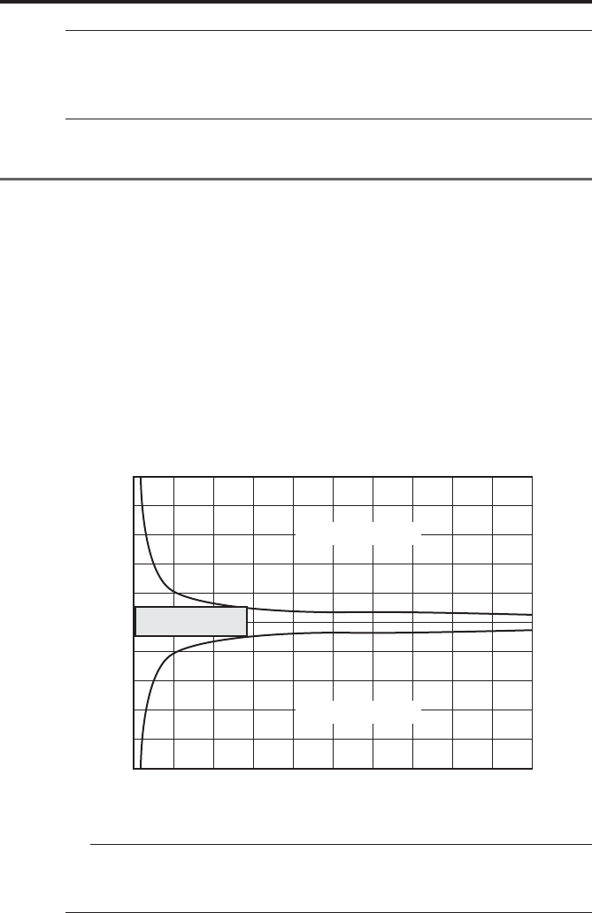
2. Overflow and calculation error
●Overflow and calculation error
Overflow conditions of DP-1VR and calculation error are shown below:
Overflow of DP-1VR is different due to mean value and amount of data.
This is shown in the graph overflow condition.
●Viewpoint of graph
If mean value 10 m is measured with 2 figures after the decimal point (by caliper
etc.), how much of data can be measured, is checked.
qData 10000.00 is changed to 1000000 as no decimal point.
wVertical axis 1000000 on graph is extended to the horizontal direction and
compared to the horizontal axis.
e2000 is obtained as the number of the data.
rWhen the data of the mean value 10 m is measured about 2000, it is recog-
nized that the overflow happens.
Condition of overflow
IMPORTANT
◆Overflow seldom happens in usual measurement by calipers or micrometers
etc.
◆When this unit is used for printing of a linear scale counter, overflow may
happen. Be careful when referring to a graph of this condition that overflow
may happen.
0
-10000000
-8000000
-6000000
-4000000
-2000000
0
2000000
4000000
6000000
8000000
10000000
1000 2000 3000 4000 5000 6000 7000 8000 9000 10000
Overflow region
Overflow region
Data mean value
Data Count
- 44 -
CALCULATION METHOD
NOTICE
◆Mean value of data shows the state when the decimal point is neglected.
Ex 10.00 is changed to read 1000
NOTE
◆Mean value of the data shows the state when the decimal point of the data is
neglected.
Ex 10.00 is changed to read 1000
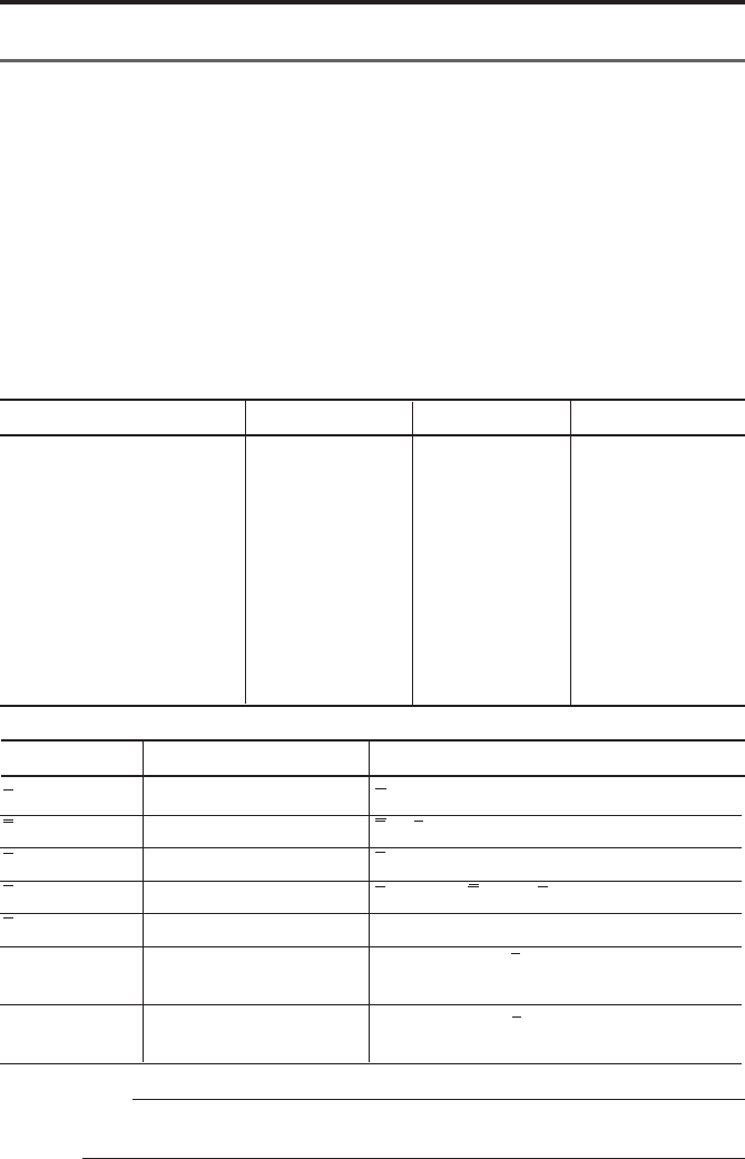
3. Calculation error detail
Calculation error of DP-1VR is shown below:
Calculation error of DP-1VR is defined as follows.
qLast figure ±1 count. Graph expresses the inside of the overflow limit of the
calculation preciseness.
Dispersion of data is set at ±5% of the mean value.
wWhen the dispersion of the mean value is far beyond the mentioned value,
calculation error is over ±5.
eFor A region (±1000000, data count less than 2000), in all cases, calculation error
is less than ±1.
Preciseness of calculation
0
-10000000
-8000000
-6000000
-4000000
-2000000
0
2000000
4000000
6000000
8000000
10000000
1000 2000 3000 4000 5000 6000 7000 8000 9000 10000
A
Overflow region
Overflow region
Data mean value
Data Count

- 45 -
CALCULATION METHOD
MAX-MIN
ΣXi/N
σn = n
((N N ΣXi2 − (ΣXi )2) / N2 )1/2
σn
-
1 =
((N N ΣXi2 − (ΣXi )2) / N N (N−1))1/2
Number of data to become LSL L Xi
Number of data to become LSL l Xi
P =
((−NG) + (+NG))/N
CP =
TOL/(6σN+1)
(TOL:USL+LSL)
CPK=
Zmin/3
Zmin: ZUSL, ZLSL Smaller value of ZLZL
ZUSL = (USL
-
X) /σn
-
1
ZLSL = (X
-
LSL) /σn
-
1
PRINT MEANING FORMULA
N
MAX
MIN
R
X
σn
σn
-
1
−
NG
+NG
P
CP
CPK
Data count
Maximum value of data
Minimum value of data
Range of data
Mean value of data
Standard deviation
Sample standard deriva-
tion
Amount of data smaller
than lower limit
Amount of data larger than
upper limit
Fraction defective
Process capability index
Process capability index
which considers deviation.
4. Calculation formula
4.1 Calculation of Mode1, Mode2
Table 2 Calculation formula 1
- 46 -
CALCULATION METHOD
SAMPLE SIZE n A2 D3 D4
2 1.880 3.267
3 1.023 2.574
4 0.729 2.282
50.577 2.114
6 0.483 2.004
7 0.419 0.076 1.924
8 0.373 0.136 1.864
9 0.337 0.184 1.816
10 0.308 0.223 1.777
X = ΣXi/ N
R = Xmax - Xmin
X = ΣXi/ n
X - UCL = X - A2 N R
R = ΣRi/ n
R - UCL = D4 N R
R - UCL = D3 N R *1
Sign Meaning Formula
X
R
X
X-UCL
R
R-UCL
R-LCL
Mean value of subgroup
Range of subgroup
Center value
Upper control limit
Center (R control)
Upper control limit
(R control)
Lower control limit
(R control)
4.2 Calculation Mode3
N : Data count
MAX: Maximum value of data
MIN: Minimum value of data
n : Number of subgroup
A2 : Refer to table
D3 : Refer to table
D4 : Refer to table
Maximum number of data in each subgroup is 10
Table 3 Mode3 table of variables
ADDITION
*1 R-LCL is not printed, when the number of samples is less than 6
- 47 -
OUTPUT
10
By connecting the optional cable (NO. 965465) to the OUTPUT connector located at
the side of this unit, either GO/±NG judgment for the input data or measured data in
RS-232C format can be output through the OUTPUT connector.
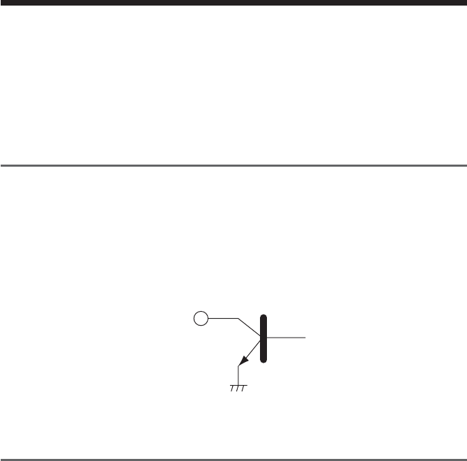
1. Output of GO/
±
NG Judgment
When the optional GO/±NG judgment result output cable (NO. 965516) is connected
to this unit, and it is in MODE0, MODE1, or MODE2 with the upper and lower
tolerance limits set. These judgment results will be output though an open collector.
2SC4047 or equivalent
Vceo (max) = 50V
IC (max) = 100mA
2. Output in Accordance with RS-232C Format
The data entered in the DP-1VR will be output to an external device in RS-232C
format when: the 'DATA' key of this unit is pressed, timer signals are input, this unit
receives a data request command via the RS-232C, or when the foot switch or data
output key is pressed on the measuring unit. However, the results of the calculations
performed in this unit are not output to an external device. Use the RS-232C conver-
sion cable (Part No. 09EAA084) to output from this unit. Also use this cable to
receive output signals in RS-323C format from the Liner Scale Counter.

- 48 -
OUTPUT
2.1 Communication Specifications
Output Signal Level: TTL Level
Communication Method: Half-Duplex
Transmission Speed: 1200, 2400, 4800, 9600, 19200
Bit Construction: Start bit 1 bit
Data bit 7/8 bits
Parity Check EVEN/ODD/NONE
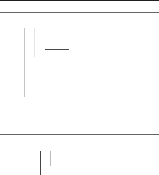
2.2 Data Format
D13D4D3D2D1 D5-D12
CR
DATA (Floating decimal point) D12LSD
Sign: positive (+) and negative (-)
Measuring item: A
Channel No.: 1
Code No.: 0
- 49 -
OUTPUT
2.3 Error Code
D4D3D2D1
CR
Error Code: 1 Data entry error
2 Entry does not satisfy the specified format
9 System error
Head temperature error
Power voltage error
Over flow
Paper error
Channel No.: 1
Error Format: 9
2.4 Data request command
D2D1
CR
Code No.: 1 or A

- 50 -
TROUBLESHOOTING
11
Checks and Remedies-Before diagnosing a problem as a defect, check the following
information.
When the DP-1VR malfunctions, diagnose the problem and remedy of the situation
with the aid of the following table.
If the problem still persists, please contact your dealer or the nearest Mitutoyo sales
office. (For the addresses, refer to the end of this manual.)
The warranty period of the DP-1VR is one year from the date of purchase for use.
Repair of this unit may be subjected to charge, depending on the case within and after
this period.

- 51 -
TROUBLESHOOTING
●Manganese dry cells are used by
mistake
●Peeling or poor fitting of the seal
is present on the battery pole
●The specified AC adapter is not
used.
●The DP-1VR supply power is
connected to the measuring
instrument.
●Input voltage to the AC adapter
(i.e. AC line voltage) is too low;
falls 5% or more than the rated
voltage
●The AC adapter is sharing the
same power line with a high-
voltage or large-current device
●The printing head is not clean
●[PRINTER ON/OFF] switch is
turned to OFF
●The printer is jammed with
paper, etc
●The DP-1VR is in the timer
input mode and the input interval is
set to 0.25 or 1 sec.
●The AC adapter is sharing the
same power line with a high-
voltage of large-current device.
●Use properly charged size AA
Nickel Hydrogen battery (Ni-Mh)
or Alkali battery (LR6)
●Correct the peeling or poor
fitting of the seal
●Use the dedicated AC adapter
09EAA088 (100/115V)
09EAA088D (230V)
09EAA088E (230V UK)
supplied with the DP-1VR
●The DP-1VR power supply
should not be connected to the
measuring device. Use a separate
power supply for each of them
●Adjust the voltage supply of the
power line correctly, and confirm
the result
●Connect the AC adapter to a
separate power line
●Clean the printing head with a
cotton swab, etc
●Press the [PRINTER ON/OFF]
switch again to turn on.
●Remove it by tweezers, etc
●When the input interval is set to
0.25 or 1 sec, the printer will be
automatically turned off.
●Connect the AC adapter to a
separate power line
When printing, the
DP-1VR unexpect-
edly returns to the
initial state seen
after the power is
turned ON.
Printing is too
light
Printer does not
print
Miscounting often
occurs on the
measuring
instrument side
Symptom Possible cause Remedies

- 52 -
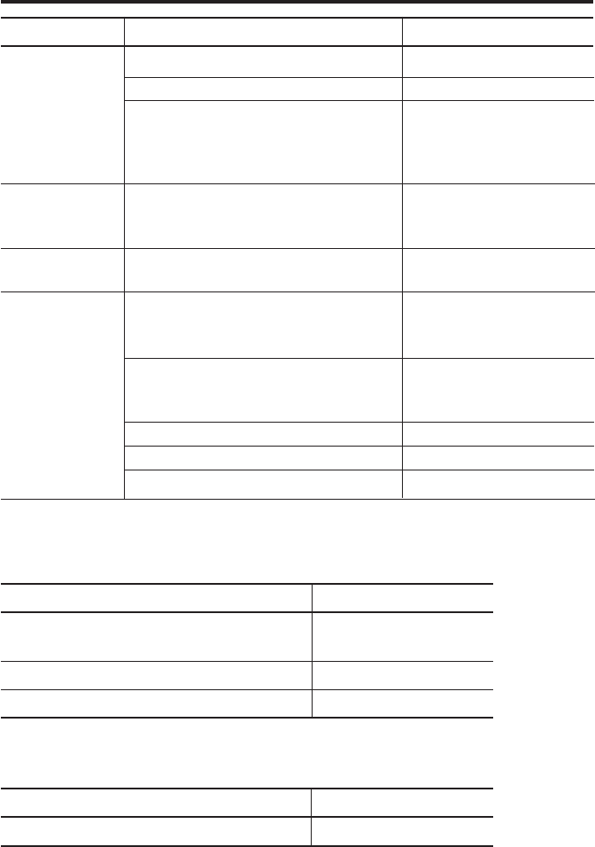
264-504
Line thermal 384 dot
36 × 24 (Large) 24 × 14 (Normal)
0.5 sec. per line
7000 lines / 1 roll (normal)/
1000 lines / 1 roll (large)
AC adapter (6V, 500 mA)
Alkali battery size AA (LR6)
Or 4 size AA Ni-MH batteries
0 ~ 45°C (AC Adapter)
10 ~ 45°C (batteries)
−10 ~ 50°C
±2 min. max / month
Approx. 10 years
10000 lines 1600 mAh Ni-MH
Printing every 5 sec.
201.1 × 94 × 75.2
(D × W × H)
390 g
Measurements, GO/±NG judgment results
Measurements, GO/±NG judgment
results, Number of measurements, MAX.,
MIN., Range, Standard deviation (σ–n,
σn-1), Number of defects, Percentage of
defects, Process capability index (CP,
CPK), Histogram
Same as above plus D-Chart
Function of calculating the center value
between the control limits required for
generating various control charts
Code No.
Printing Method
Character format
Printing Speed
Printing line
numbers per
printing roll
Power supply
Operating
Temperature
Storage Tempera-
ture
Accuracy
Clock battery life
expectancy
Battery life
Dimensions
Weight
Printouts
100V
When using AC adapter
Dual power supply
*AC adapter input voltage
within a range of 100VAC
±5%
In a package as specified by
Mitutoyo
Average life expectancy
Average life expectancy but
valies with usage
Without accessories
Mode 0
Mode 1
Mode 2
Mode 3
Item Description Remarks
SPECIFICATIONS
12
- 53 -
SPECIFICATIONS
100000
9999
10 × 9999 = 99990
(Sample size × Number of sub-groups =
total number of measurements)
5 sets of limit data
Measured data (RS-232C, TTL level)
GO/±NG
Judgment results (+NG, GO, −NG)
0.25 sec, 1 sec, 5 sec, 30 sec, 1 min, 30
min, 60 min.
AC Adapter
Recording paper: 1 pc.
(58 mm (W) × 48 m (L))
Strap
Quick Reference
User’s manual
Processing
capability
Output function
Timer-controlled
data input
Standard accesso-
ries
Item Description Remarks
Mode 0
Both Mode 1 and 2
Mode3
110V/115V 09EAA088
230V 09EAA088D
230V (UK) 09EAA088E
When ordering
Part No. 09EAA082
(10 pcs.)
09EAA079
09EAA090
99MBE021
Optional accessories:
Item Name Parts No.
RS-232C conversion cable No. 09EAA084
9 pins for AT connector
GO/±NG judgment result output cable No. 965516
Foot Switch No. 937179T
Consumables:
Item Name Parts No.
Printing Paper (10 packs) No. 09EAA082

- 54 -
SPECIFICATIONS
MTI Corporation
New Jersey Office
18 Essex Road, Paramus, N.J. 07652, U.S.A.
TEL: (201)368-0525 TELEX: 134317 FAX: (201)343-4969
Detroit Office
45001 Five Mile Road, Plymouth, M? 48170, U.S.A.
TEL: (313)459-2810 FAX: (313)459-0455
Chicago Office
965 Corporate Blvd., Aurora, IL 60504, U.S.A.
TEL: (708)820-9666 FAX: (708)820-7403
Dallas Office
2410 Gateway Drive, Irving TX 75062, U.S.A.
TEL: (214)550-8645 FAX: (214)550-8861
Los Angeles Office
16925 East Gale Ave., city of Industry, CA91745, U.S.A.
TEL: (818)961-9661 FAX: (818)333-8019
MTI Canada Ltd.
2121 Meadowvale Blvd., Missiassauga, Ont, L5N 5N1,
CANADA
TEL: (905)821-1261~3 FAX:(905)821-4968
Mitutoyo do Brasil Industria e Comercio Ltda.
AV. Joao Carlos da Silva Borges, 1240, CEP 04726
Santo Amaro P.O. Box 4255 Sao Paulo, BRASIL
TEL: (011)522-7755 TELEX: 1123768 MTOY BR
FAX: (011)523-3661
Mitutoyo Mexicana S.A. de C.V.
Ave. Primero de Mayo No. 236-A San Andres, Atoto 53500
Naucalpan, Edo. de MEXICO
TEL: 576-8799 TELEX: 1772007 FAX: (915)576-8039
Mitutoyo Mebgerate GmbH
Borsigstr. 8-10, 41469 Neuss F.R. GERMANY
TEL: (02137)102-0 TELEX: 8517702 FAX: (02137)8685
Mitutoyo Nederland B.V.
Postbus 550, Landjuweel 35, 3905 PE Veenendaal,
NETHERLANDS
TEL: 08385-34911 FAX: 08385-16568
Mitutoyo Scandinavia A.B.
Box 712, Stockholmsvagen 26, 194 27 Upplands-Vasby,
SWEDEN
TEL: (08)590 921 35 TELEX: 15353 FAX: (08)590 924 10
Mitutoyo Belgium N.V.
Hogenakkerhoek straat 8, 9150 Kruibeke, BELGIUM
TEL: (03)8303063 FAX: (03)8278360
Mitutoyo France S.A.R.L.
123, rue de la Belle Etoile, B.P. 50267-Z.I. Paris Nord II
95957 Roissy CDG Cedex, FRANCE
TEL: (01)49 38 35 00 TELEX: 233913 FAX: (01)49 38 35 35
SERVICE NETWORK
Mitutoyo France S.A.R.L., Agence de Lyon
Bat L133, avenue du Dr. Georges Levy 69200
VENISSIEUX
TEL: (16)78752010
Mitutoyo Italiana S.R.L.
Corso Europa No.7, 20020 Lainate, Milano, ITALY
TEL: (02)935781 FAX: (02)9373290
Mitutoyo Schweiz AG
Steinackerstrasse 35, 8902 Urdorf-Zurich, SWITZERLAND
TEL: (01)7361150 FAX: (01)7361151
Mitutoyo (U.K.) Ltd.
Joule Road, West Point Business Park, Andover,
Hampshire
SP10 3UT UNITED KINGDOM
TEL: (01264)353123 TELEX: 477694 FAX: (01264)354883
Mitutoyo Asia Pacific Pte. Ltd.
Reginal Headquarters
24 kallang Avenue, Mitutoyo Building, SINGAPORE 339415
TEL: 294-2211 TELEX: RS 25875 MTYSIN FAX: 299-6666
Malaysia
Head office
Mitutoyo (Malaysia) Sdn. Bhd.
Lots 1-8 Ground Floor, Asia Jaya Commercial Complex,
Section 52, 46200 Peteling Jaya, Selangor, MALAYSIA
TEL: (60)3-757-2524 FAX: (60)3-757-2540
Panan Branch Office
No.9 Jalan Selat, Taman Selat 12000, Butterworth, Penang,
MAYALYSIA
TEL: (60)4-310915/8 FAX: (60)4-310907
Johor Office
20A, Jalan Abiad, Taman Tebrau Jaya 80400, Johor Bahru,
Johor, MAYALYSIA
TEL: (60)4-310915/8 FAX: (60)7-336861
Thailand:
Representative Office
9th Floor, Unit D2-3, MBK Tower, 444 Phayathai Road,
Bangkok, THAILAND 10330
TEL: (66)2-217-9651/3 FAX: (66)2-217-9654
India:
Representative Office
702, Arunachal Building, 19, Barakhamba Road,
New Delhi-110001, INDIA
TEL: (91)11-332-4419 TELEX: 031-62939 MAP IN
Mitutoyo Taiwan Co., Ltd.
5th FL. No. 123, Wu Kung First Road, Wu Ku Industrial
Park, Taipei Hsien, TAIWAN, R.O.C
TEL: (02)299-5266 FAX (02)299-2358
Please contact your nearest technical service center, for problems or questions about this
product.
Mitutoyo Corporation
20-1, Sakado, 1-chome, Takatsu-ku, Kawasaki, Kanagawa 213-0012, Japan Printed in Japan
