Monnit RFSC1 Monnit Wireless Sensor Module User Manual
Monnit Corporation Monnit Wireless Sensor Module
Monnit >
Contents
- 1. User Manual
- 2. Updated User Manual
User Manual
Monnit Wireless Sensors
and iMonnit Online Monitoring System
User Guide
Monnit Wireless Sensors
and iMonnit Online Monitoring System
User Guide
2 | M-UG01-3A | www.monnit.com | © 2011 Monnit Corp.
3 | M-UG01-3A | www.monnit.com | © 2011 Monnit Corp.
Contents
About Monnit
System Requirements
The Monnit Wireless Hardware
MonnitLink Ethernet Gateway
MonnitLink USB Gateway
Monnit WIT Wireless Sensors
Monnit Wireless Repeater
MonnitLink USB Sensor Network Software Installation
MonnitLink USB Driver Installation
Monnit Gateway Application Installation
Hardware Installation (Bringing Sensors Online)
Using the iMonnit System
Logging into iMonnit.com
iMonnit User Interface (Overview)
Using “My Account” (Account and Contacts)
Selecting the Date Range
Using the Sensor List
ConguringSensors(Basic)
ConguringSensors(Advanced)
CongureMultipleSensorsSimultaneously
SettingUpNoticationsandAlerts
History and Chart Views
Exporting Data (To File)
Exporting Data to an External Source
Sensor Maps
Reports
Error Reporting, Troubleshooting and Support
Warranty Information
Certications(FCCandIC)
4
5
6
7
8
9
10
11
12
13
15
16
17
19
20
21
22
23
25
26
28
29
30
31
33
33
34
4 | M-UG01-3A | www.monnit.com | © 2011 Monnit Corp.
About Monnit Corp.
Monnit is a leader in the design and manufacture of turnkey,
self-installing, low cost wireless sensor solutions targeted at
the commercial, industrial and consumer markets. Monnit’s
sensing solutions are designed to be easily installed and
used by anyone wanting to remotely monitor information and
activities, including: access, presence of water, luminosity,
temperature, humidity, and vibration in or around structures,
machinery, and various environments.
Please Read Before Proceeding
THE WIRELESS SENSORS ARE ACTIVE AND HAVE ALREADY BEEN
ASSIGNED TO YOUR CUSTOMER SENSOR NETWORK. YOUR WAR-
RANTY IS INVALIDATED IF YOU DISASSEMBLE OR ATTEMPT TO
DISASSEMBLE ANY OF THESE DEVICES.

5 | M-UG01-3A | www.monnit.com | © 2011 Monnit Corp.
Network and Computer Requirements
MonnitLink™ USB Gateway
Computer System Requirements
To use your wireless sensors with a MonnitLink USB
Gateway you will need a Windows PC with the following:
•AMonnitLink™ USB Wireless Gateway
•WindowsXPwith512MBMemory
(Windows 7 with 1024 MB Recommended)
•20MBFreeDiskSpace
•ASP.NET3.5
( http://www.asp.net/downloads/essential )
MonnitLink™ Ethernet Gateway
To use your wireless sensors with a MonnitLink Ethernet
Gateway you will need the following:
•AMonnitLink™ Ethernet Wireless Gateway
•An Internet enabled router with one available
Ethernet port or a direct internet ethernet
connection.

6 | M-UG01-3A | www.monnit.com | © 2011 Monnit Corp.
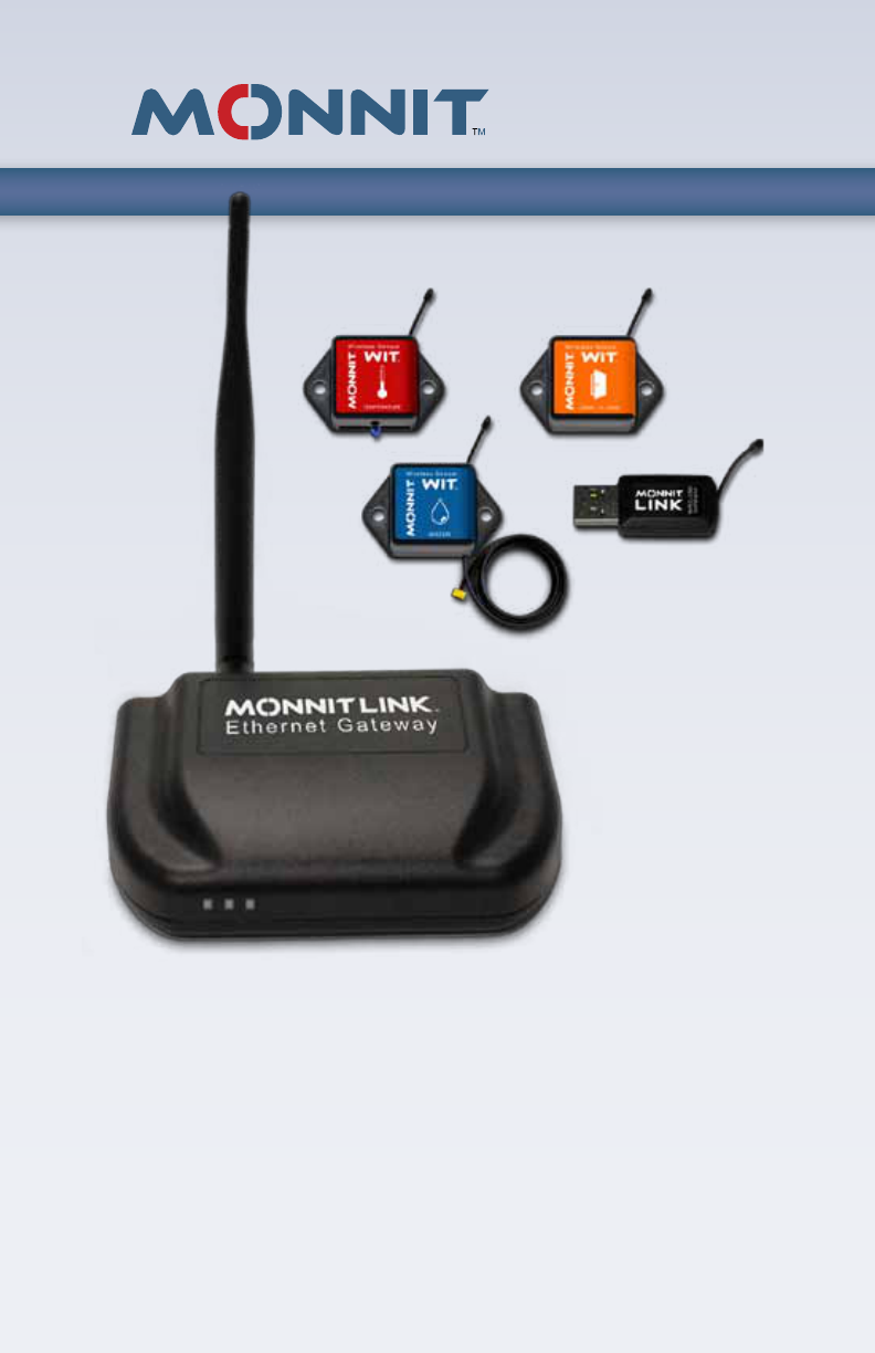
Monnit Wireless Hardware
Monnit wireless sensor networks consist of MonnitLink™
Wireless Gateways, Monnit WIT™ Wireless Sensors and
Monnit Sensor Monitoring Software such as iMonnit™ On-
line, Monnit Express™ PC Software and Monnit Enterprise™
Server Software.
The simplest way to get started with Monnit wireless sensors
is to select either a USB or Ethernet version of the gateway
and monitor your sensors online through the iMonnit Online
SensorMonitoringandNoticationSystem.
MonnitLink USB Gateways require the use of a personal
computerrunningwindowsXPorlaterandrequiresthatthe
computer remain running and connected to the internet in
able for the sensors to communicate to the online system. A
MonnitLink Ethernet Gateway is a standalone unit that oper-
ates continuously without the need for a computer and only
requires an Ethernet connection with access to the Internet.
RF Specications
Operating Frequency 902 MHz - 928 MHz
Power Output +8 dBm
Receiver Sensitivity -102 dBm
RF Range 250 - 300 ft. non-line-of-sight
Modulation Frequency Shift Keying (FSK)
7 |
M-UG01-3A | www.monnit.com | © 2011 Monnit Corp.
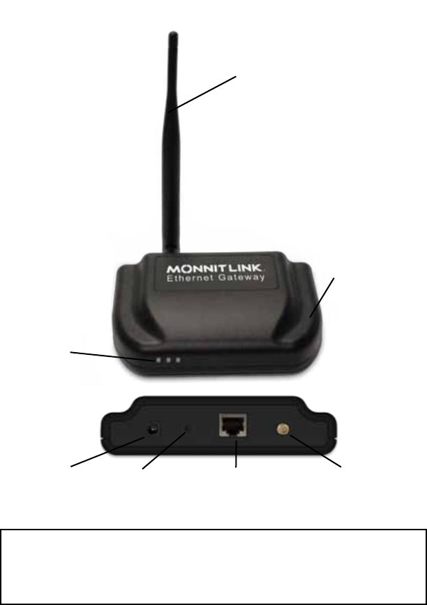
Rugged Plastic
Enclosure
RP SMA Antenna
Power Plug Control Button RP SMA Antenna ConnectorEthernet Port
MonnitLink™ Ethernet Gateway
Indicator
Lights
This device has been designed to operate with an approved antenna listed on page 11, and having a
maximum gain of 5.1 dBi. Antennas not included in this list or having a gain greater than 5.1 dBi are
strictly prohibited for use with this device. The required antenna impedance is 50 ohms.
To reduce potential radio interference to other users, the antenna type and its gain should be so chosen
that the equivalent isotropically radiated power (EIRP) is not more than that required for successful
communication.
FCC Approval (USA) - Refer To Page 34 for FCC Requirements.
IC Approval (Canada) - Refer To Page 35.
Contains FCC ID: ZTL-RFSC1 & IC: 9794A-RFSC1
This device complies with Part 15 of the FCC Rules. Operation is subject to the following two
conditions: (1) this device may not cause harmful interference and (2) this device must accept
any interference received, including interference that may cause undesired operation.
8 | M-UG01-3A | www.monnit.com | © 2011 Monnit Corp.
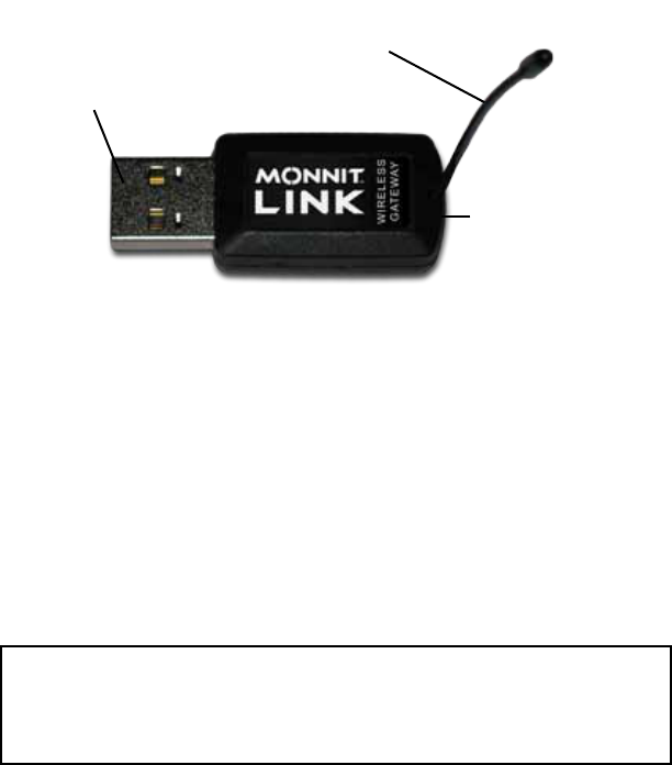
USB Interface
Rugged Plastic
Enclosure
3” Whip Antenna
MonnitLink™ USB Gateway
FCC ID: ZTL-RFUSB1 & IC: 9794A-RFUSB1
This device complies with Part 15 of the FCC Rules. Operation is subject to the following two
conditions: (1) this device may not cause harmful interference and (2) this device must accept
any interference received, including interference that may cause undesired operation.
This device has been designed to operate with the attached non-removable antenna.
FCC Approval (USA) - Refer To Page 34 for FCC Requirements.
IC Approval (Canada) - Refer To Page 35.
9 | M-UG01-3A | www.monnit.com | © 2011 Monnit Corp.
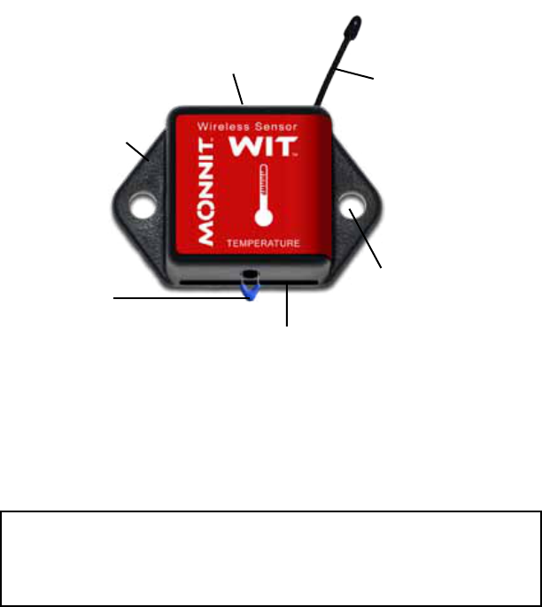
Rugged Plastic
Enclosure
Battery Slot
Mounting Tabs
Battery
Removal Hole
4” Whip Antenna
External
Sensor
Monnit WIT™ Wireless Sensors
This device has been designed to operate with an approved antenna listed on page 11, and having a
maximum gain of 5.1 dBi. Antennas not included in this list or having a gain greater than 5.1 dBi are
strictly prohibited for use with this device. The required antenna impedance is 50 ohms.
To reduce potential radio interference to other users, the antenna type and its gain should be so chosen
that the equivalent isotropically radiated power (EIRP) is not more than that required for successful
communication.
FCC Approval (USA) - Refer To Page 34 for FCC Requirements.
IC Approval (Canada) - Refer To Page 35.
Contains FCC ID: ZTL-RFSC1 & IC: 9794A-RFSC1
This device complies with Part 15 of the FCC Rules. Operation is subject to the following two
conditions: (1) this device may not cause harmful interference and (2) this device must accept
any interference received, including interference that may cause undesired operation.
10 | M-UG01-3A | www.monnit.com | © 2011 Monnit Corp.
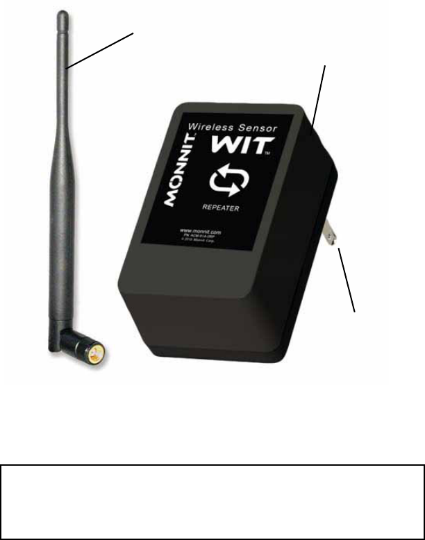
Rugged Plastic
Enclosure
Monnit Wireless Repeater
This device has been designed to operate with an approved antenna listed on page 11, and having a
maximum gain of 5.1 dBi. Antennas not included in this list or having a gain greater than 5.1 dBi are
strictly prohibited for use with this device. The required antenna impedance is 50 ohms.
To reduce potential radio interference to other users, the antenna type and its gain should be so chosen
that the equivalent isotropically radiated power (EIRP) is not more than that required for successful
communication.
FCC Approval (USA) - Refer To Page 34 for FCC Requirements.
IC Approval (Canada) - Refer To Page 35.
Contains FCC ID: ZTL-RFSC1 & IC: 9794A-RFSC1
This device complies with Part 15 of the FCC Rules. Operation is subject to the following two
conditions: (1) this device may not cause harmful interference and (2) this device must accept
any interference received, including interference that may cause undesired operation.
RP SMA Antenna
Power Plug

11 | M-UG01-3A | www.monnit.com | © 2011 Monnit Corp.
MonnitLink™ USB Sensor Networks
(The following information is for sensor networks using a MonnitLink™ USB
Gateway. If using a MonnitLink™ Ethernet or Cellular Gateway skip to page 12.)
Before inserting the MonnitLink™ USB Gateway into your comput-
er, you will need to install the USB Drivers and the Monnit Gate-
way Application which will allow your sensor network to communi-
cate with the iMonnit™ Online Sensor Monitoring System.
Note: If you purchased the Monnit Express™ standalone PC applica-
tion, then you will have received an email with download and installation
instructions. If you have lost the email please contact a Monnit represen-
tative to have the email resent.
MonnitLink™ USB Driver Installation
The latest MonnitLink™ USB drivers can be installed directly from
the web or downloaded for manual installation.
http://www.monnit.com/support/downloads.php
From the downloads page, click on MonnitLink™ USB Driver In-
stallertolaunchthewebinstallerdownload.Thedriverleshould
automaticallystartdownloading,ifpromptedtosavethele,select
a location that is easily accessible and click “Save”.
Whenthelehascompleteddownloading,browsetothefolder
wherethelewassaved.Doubleclickthe“Monnit-Driver-Setup.
exe”leandselect“Run”.Select“Next”thenfollowtheon-screen
guide to install the drivers.
Whenthesetuphasnished,theprogramwillautomaticallyde-
termine which drivers to install for your system and another guide
will launch to guide you through the installation of the drivers. Click
“Next” to install the drivers. When the drivers are done installing
you will see a success screen. Click “Finish” to exit the installation
program.
Note: Tomanuallyinstallthedriveryoucandownloadtheappropriatele
from the downloads page and follow the included instructions.

12 | M-UG01-3A | www.monnit.com | © 2011 Monnit Corp.
Monnit Gateway Application Installation
The Monnit Gateway Application allows your wireless sensors
to communicate with the iMonnit™ Online Sensor Monitoring and
NoticationSystem.(iMonnitallowsyoutoviewallyoursensor
data,sensorstatus’andcongureallsensorparametersaswell
assetupnoticationsoralertsviasmstextandemail.)
To install the software, open a web browser and navigate to
http://www.monnit.com/support/downloads.php. From the down-
loads page, click on “Monnit Gateway Application Installer” to
launchthewebinstallerdownload.Ifpromptedtosavethele,
select a location that is easily accessible and click “Save”.
Whenthelehascompleteddownloading,browsetothefolder
wherethelewassaved.Doubleclickthe“MonnitGatewaySetup.
msi” le,select“Run”whenpromptedthenfollowtheon-screen
instructions to complete the installation.
When installation is complete the program will automatically
launch. You can now begin using your Monnit wireless sensors
online.
Note: The Monnit Gateway application needs to be running on your
computer in order for the sensor data to be transmitted to the iMonnit
Online System. If the gateway is not running your sensor data is not
beingrecordedandnoticationsbasedonsensordatacannotbe
sent from the system.
13 | M-UG01-3A | www.monnit.com | © 2011 Monnit Corp.
Launch the Monnit Gateway Application:
From the Windows “Start Menu” under “All Programs” >
“Monnit” click on “Monnit Gateway”.
(Skip this step if using an Ethernet or Cellular Gateway)
Insert the MonnitLink™ USB Wireless Gateway:
With the Monnit™ Gateway application running, insert the
MonnitLink™ USB into your computer. The network status in
the software should change to active when the USB gateway
has been plugged in.
(Skip this step if using an Ethernet or Cellular Gateway)
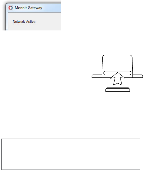
Insert batteries into the sensors:
Peel back the black sticker cover of
the battery slot and slide the coin
cell battery into the sensor. It will
power on within 10-20 seconds.
Note: Note the proper orientation of
batterying.1.Wheninserting,make
sure to push the battery all the way back.
Check that Sensor Data is Being Recieved:
As the sensors power up, they will check into the Monnit-
Sphere Gateway and transmit their current reading. Your
gateway window should look similar to this:
+
_
Battery
Insertion
g.1
Bringing Sensors Online
(If the status does not change,
try unplugging and re-inserting
the USB gateway.)
06/24/201109:44:57.939:RX:SensorData:Device:10721SensorType:Temperature[2],
RSSI: -21 / -31, Volts: 2.96V, STS: 16, Data: 72.3° F
06/24/201109:44:57.375:RX:StatusIndication:Device:10721hasjoinednetwork
06/24/201109:44:42.274:RX:NetworkStatus:APN:2116,NetCNT:4,Channel:4,
NetID: 248, MODE: "ACTIVE/RESUME"
Network Active
14 | M-UG01-3A | www.monnit.com | © 2011 Monnit Corp.
Continued...
If a sensor does not join the network when a battery is
inserted, try cycling the power by removing and re-inserting
the battery. (You should wait 45 seconds before re-inserting
thebattery.)Onceyouhaveveriedthatyoursensorsareall
powered on and have checked into the MonnitSphere Gate-
way they are ready to be deployed. If you wish to change
asensorconguration,alloftheparametersareeditablein
the MonnitSphere online software. The new parameters will
be downloaded to the Wireless Gateway every 5 minutes,
then transmitted to the sensors on their next heartbeats. If
you need more immediate response from a sensor, you can
press the “Download Sensor Updates” button in the Monnit
Gateway applicaton, then cycle the sensor by removing, then
re-inserting the battery.
15 | M-UG01-3A | www.monnit.com | © 2011 Monnit Corp.
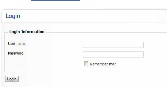
Open any Internet Browser and navigate to the iMonnit
website at www.imonnit.com.
Enteryourusernameandpasswordintheappropriateeld
and click the “Login” button to continue.
Your username and password are included on the informa-
tion sheet that shipped with your sensors.
Note: You will be prompted to change your password when you
loginforthersttime.
Using the iMonnit™ Online System
Logging into iMonnit™
16 | M-UG01-3A | www.monnit.com | © 2011 Monnit Corp.
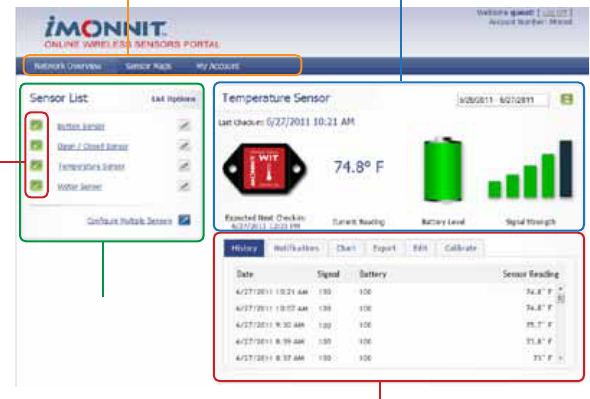
3. Sensor Status Indicators
5. Sensor Data Window
1. Menu System 4. Current Sensor Quick Stats
2. Sensor List
Menu System
Provides quick links to areas of the software for navigational
purpose.
Network Overview
Displays a list of all wireless sensor networks associated
with the account. Clicking on a network name will change the
current view to the selected network.
Sensor Maps
Visual Tool for uploading a building blueprint or schematic,
allowing you to visually place sensor tags on the map. Clicking on
the sensor graphics gives you a quick view of the latest sensor
reading and status.
My Account
Access and edit account information and system users.
Reports
Access reports for your account.
iMonnit User Interface (Overview)

17 | M-UG01-3A | www.monnit.com | © 2011 Monnit Corp.
Sensor List
Displays all sensors that are currently assigned to your sen-
sor network. Clicking on a sensor name allows you to select
which sensor information is viewable on-screen. Clicking
the edit button by a sensor’s name allows you to change the
sensorspecicsettingssuchassensornameandheartbeat
(reportinterval)aswellasadvancedsensorconguration
information that is stored on the sensor hardware.
Sensor Status Indicators
Displays the status for each individual sensor.
Current Sensor Quick Stats
Displays the most current information from the selected
sensor, including: sensor name, signal strength, battery
power and sensor reading / status.
Sensor Data Window
The sensor data window displays content according to the
selected sensor data tab. There are four different views
available.
History - Displays a history of the data sent from the selected
sensor.
Alerts - Allows you to view, create, edit or delete user
customizablenoticationsfortheselectedsensor.
Chart - Displays a graphical view of the readings sent from
the selected sensor.
Export -Youcanarchivedatabyexportingasa.csvleor
send the sensor data to an external source.
Calibrate - Allows you to calibrate your sensors by correcting a
current reading, and applying the adjustment to all
future readings. (Only available on applicable sensors.)
Sensorischeckinginandwithinuserdenedsafeparameters.
Sensor has not checked in.
Sensorhasmetauserdenedthresholdortriggeredevent.
18 | M-UG01-3A | www.monnit.com | © 2011 Monnit Corp.
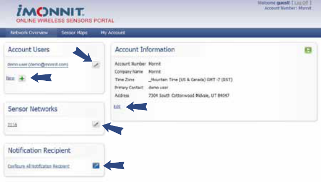
Edit Account Information
Allows you to change general account information such as; com-
pany name, address, time zone and primary contact.
Create New Account User
Allows you to create new users for the account by entering contact
information and sensor network permissions.
Edit Account User
Allows you to change contact information, change login password
and change sensor network permissions.
Edit Sensor Networks
Allows you to change the name of the sensor network and enable
ordisablenoticationsforallsensorslocatedinthatnetwork.
Congure All Notication Recipient
Allowsyoutocreateacontactthatwilloverwriteallexistingnoti-
cations for all sensors and networks within the account.
Note:Usingthisfunctionwilloverwriteallexistingnotications
setup in the account.
Using “My Account” (Account and Contacts)
Clicking on the “My Account” link in the navigation bar will open
the account settings page. From here you have the ability to edit
your account information, manage users, and create a master
recipient for all messages from the system.
19 | M-UG01-3A | www.monnit.com | © 2011 Monnit Corp.
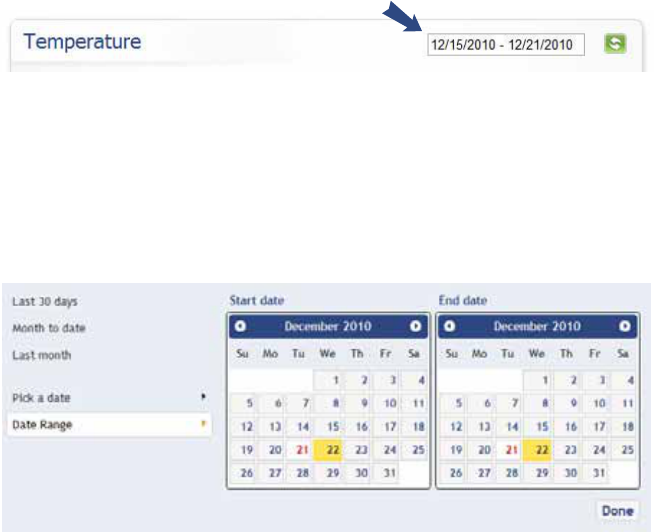
Selecting the Date Range
All of the sensor information viewed through the user interface is
selectable by a “Date Range”. The default view for the system is
the past 30 days. To change this simply click on the date range
box at the top of the sensor data window.
After clicking on the date range box, the following pop-up win-
dow will appear. You can click on any of the pre-determined date
congurationsintheleftcolumnorselect“PickaDate”toview
singledaydataforagivendateorselect“DateRange”todenea
specicrangeofdates.
Note: The current date is highlighted in yellow, while your selected dates
will be displayed in red.
20 | M-UG01-3A | www.monnit.com | © 2011 Monnit Corp.
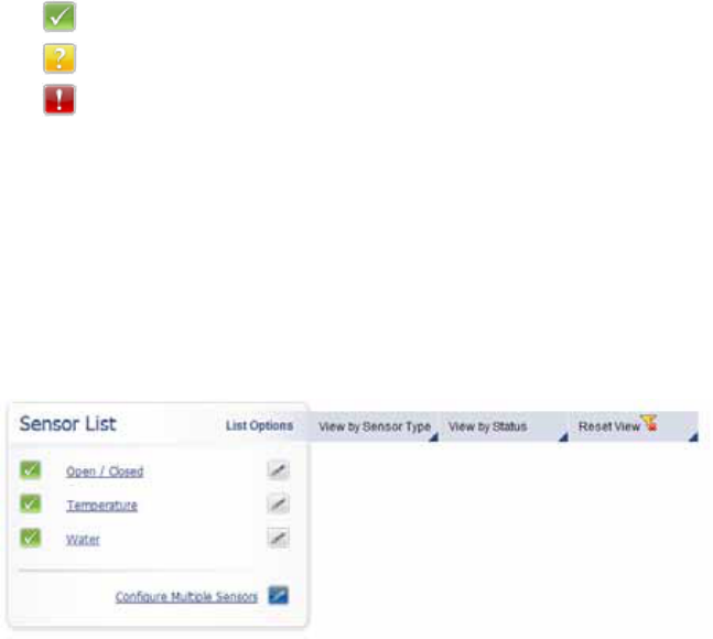
Using the Sensor List
The sensor list provides a quick view of the status for all sensors
in the selected network as well as providing quick link access to
sensordataandcongurationwindows.
The following is a summary of the status indicators and what they
mean.
Clicking on the name of a sensor in the list opens the sensor dis-
play view and clicking on the “Edit” icon by each name opens the
sensorcongurationwindow.
List Options (Sorting the Sensor List)
For larger sensor networks, we have provided a way to easily sort your
sensor list to only show sensors by “Type” or “Status”.
Toactivateasortinglteronthelist,mouseover“ListOptions”
andselectthelteryouwouldliketoapply.Toresettothedefault
sensor list view select “Reset View”.
Sensorischeckinginandwithinuserdenedsafeparameters.
Sensor has not checked in for the past 3 heartbeats.
Sensorhasmetauserdenedthresholdortriggeredevent.
21 | M-UG01-3A | www.monnit.com | © 2011 Monnit Corp.
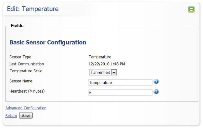
Conguring Sensors (Basic)
Click the “Edit” icon next to the name of the sensor that you would
liketocongure.(Youcanalsoclickonthe“Edit”tabinthesen-
sor information window.)
Thebasicsensorcongurationwindowallowsyoutosetthe
primarycongurationsforeachsensor.Thebasiccongurations
willsufceforthemajorityofusers.Withinthiswindowyoucan
name your sensor, set the heartbeat (how frequently the sensor
will take a reading and communicate with the MonnitSphere online
monitoringandnoticationsystem),andselecttheunitsofmea-
surementetc.Ifmoreadvancedcongurationsareneeded,click
on“AdvancedConguration”linkabovethe“Save”button.
Note: Be sure to click the “Save” button anytime you make a change to
anyofthecongurationelements.
22 | M-UG01-3A | www.monnit.com | © 2011 Monnit Corp.
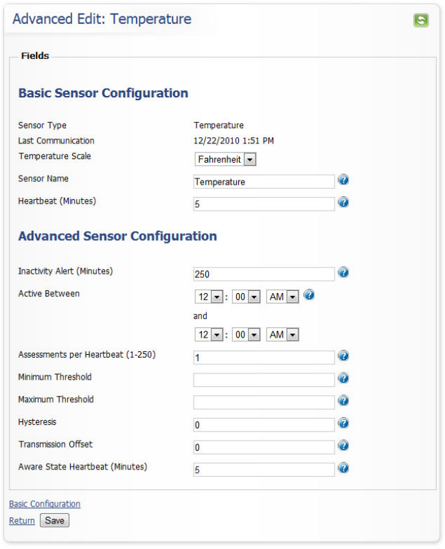
Conguring Sensors (Advanced)
Alloftheadvancedcongurationsettingsaretransmittedtothe
sensor and stored on the sensor hardware. These settings allow
the sensor to act differently, independent of the software.
23 | M-UG01-3A | www.monnit.com | © 2011 Monnit Corp.
Advanced Sensor Setting Denitions
Inactivity Alert (Minutes)
The amount of time that elapses without a heartbeat before you are noti-
ed.Thedefaultis3timesthesetheartbeatinterval.
Active Between
The time of day the sensor is actively working. No communication will be
sent while sensor is hibernating.
Assessments per Heartbeat
How many times between heartbeats a sensor will check its measure-
ments against its thresholds to determine whether it will enter the aware
state.
Minimum Threshold
Any assessments below this value will cause the sensor to enter the
aware state.
Maximum Threshold
Any assessments above this value will cause the sensor to enter the
ware state.
Hysteresis
A buffer to prevent the sensor from bouncing between standard operation
and the aware state when the assessments are very close to a threshold.
For example, if a maximum threshold is set to 90° and the hysteresis is
set to 1°, when a sensor takes an assessment of 90.0° and enters the
aware state it will remain in the aware state until the temperature reading
drops to 89.0°. Similarly, at the minimum threshold the temperature will
have to rise 1° above the threshold to return to standard operation.
Transmission Offset
In large sensor networks, offset is used to prevent all sensors from trans-
mitting simultaneously; therefore minimizing communication disruption.
Aware State Heartbeat
How often the sensor communicates with the gateway while in the aware
state.
24 | M-UG01-3A | www.monnit.com | © 2011 Monnit Corp.
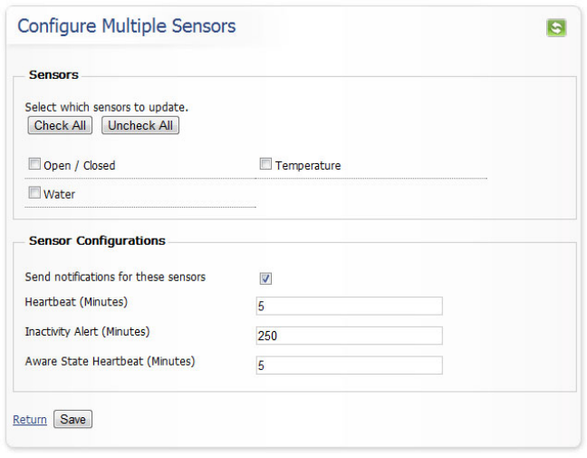
Congure Multiple Sensors Simultaneously
Youcanmakecertaincongurationstomultiplesensorsbyclick-
ingon“CongureMultipleSensors”atthebottomoftheSensor
List Window. Click the checkboxes in front of all sensors that you
would like to apply the settings to, then click “Save” to apply the
same settings for all selected sensors.
Note:Settingsconguredthroughthiswindowwilloverwriteanycustom
settings currently set for the selected sensors.
25 | M-UG01-3A | www.monnit.com | © 2011 Monnit Corp.
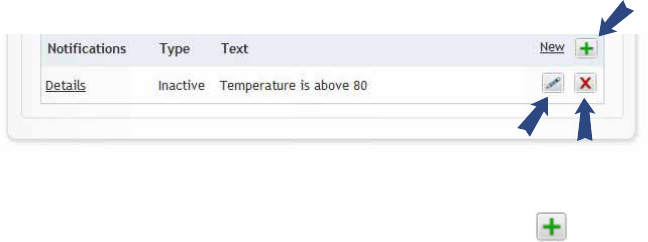
Setting Up Notications and Alerts
Clickingonthe“Notications”tabwithinthesensordatawindow
willbringupalistofsentnoticationsaswellasalistofall
currentlysetupnoticationsandalerts.
Tocreateanewnoticationoralert,clickonthe“New”icon
at the bottom right of the window. To edit or delete an existing
notication,clickonthe“Edit”iconorthe“Delete”icon.
Edit Delete
New
26 | M-UG01-3A | www.monnit.com | © 2011 Monnit Corp.
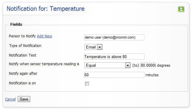
Creating a New Notication or Alert
Person to Notify
Start typing a name into the box and the system will show all users with
a similar name, if you need to create a new user click “Add New”.
TypeofNotication
Allowsyoutochoosethenoticationdeliverymethod(EmailorSMS.)
NoticationText
Thisisauserdenedmessagethatwillbeemailedortextedtothe
recipient when the conditions have been met.
Sensor Conditions for Alert
This area is dependant upon what type of sensor is being used. For
example a temperature sensor will ask for a condition that when met will
trigger the alert, such as a temperature above 80°.
Notify Again After
Allowsyoutodenehowfrequentlyyouwanttobenotiedifthesensor
condition is still met or exceeded. For example, if the temperature is still
above80°Icanbenotiedevery10minutesuntilIhaveaddressedthe
issue.
NoticationisOn
Allowsyoutoturnoffanoticationtemporarily,withoutdeletingit.
27 | M-UG01-3A | www.monnit.com | © 2011 Monnit Corp.
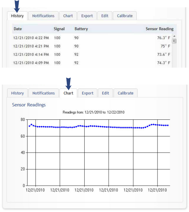
History and Chart Views
Clicking on the “History” or “Chart” tabs within the sensor data
window allows you to view the sensor data history as text or in a
graphical chart.
To change the date range of the viewable information, click on the
date range box at the top right of the sensor data window.
28 | M-UG01-3A | www.monnit.com | © 2011 Monnit Corp.
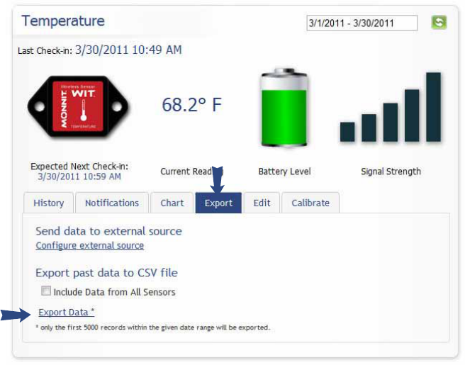
Exporting Data
Clicking on the “Export” tab within the sensor data window allows
youtoexportsensordatatoacommaseparatedvalue(.csv)le
or send the sensor data to an external web source.
Toexportsensordatatoacommaseparatedvalue(.csv)lefor
use in spreadsheet software such as Microsoft Excel®, click on
“Export Data” at the bottom of this window. The default value will
export data for the viewed sensor only, if you would like to include
data for all sensors in the viewed network, click the checkbox by
“Include Data from All Sensors”.
Note:Onlytherst5,000recordswithintheselecteddaterangewillbe
exported, you can adjust the date range to export more data if needed.
29 | M-UG01-3A | www.monnit.com | © 2011 Monnit Corp.
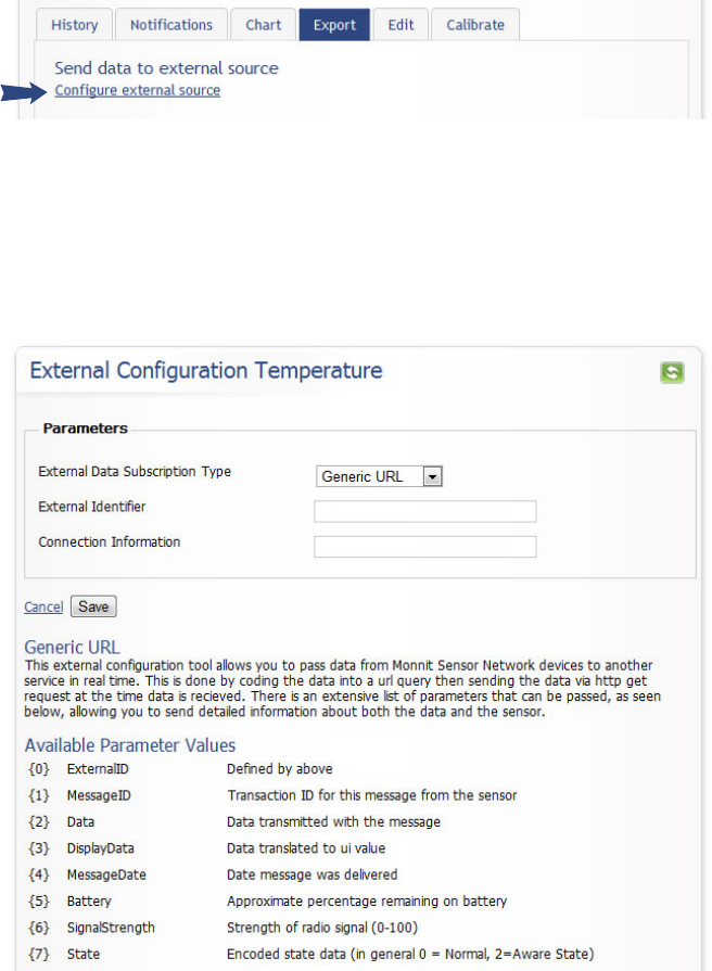
Exporting Data to an External Source
To send the sensor data to an external web source, click on “Con-
gureExternalSource”.
On this page you can select the “External Data Subscription Type”
which can be a Generic URL or an external service that is cur-
rently registered with the MonnitSphere System such as Sensing
Planet™. If you are using a registered external subscription ser-
viceenteryour“ExternalIdentier”and“ConnectionInformation”.
All available parameters are listed on the page.
30 | M-UG01-3A | www.monnit.com | © 2011 Monnit Corp.
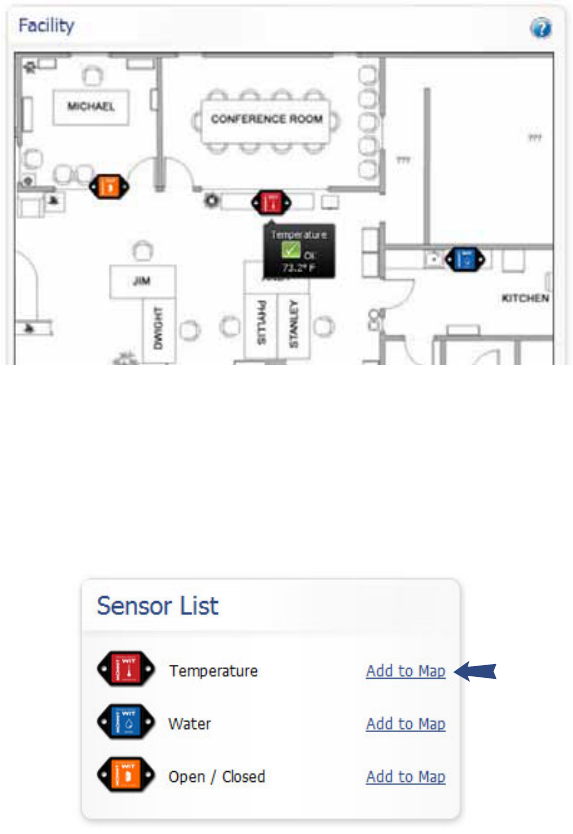
Sensor Maps
By clicking on “Sensor Maps” in the main navigation bar you can
access MonnitSphere’s Visual Sensor Mapping Tool. This tool
allows you to upload a graphic of your building or sensor area,
and visually place sensor tags on the graphical map to remind
you where sensors have been placed. The tool also allows for one
click access to current sensor readings and status.
To create a new sensor map, click on the “New” icon. In the pop-
up window, type a name for your map and then click “Choose
File” to browse your computer for the graphic you would like to
upload. Click “Create” to save the map to your list. Once your
map is created, you can add sensors from your sensor list to the
map by clicking on “Add to Map” by each sensor.
31 | M-UG01-3A | www.monnit.com | © 2011 Monnit Corp.
Once the sensors have been added to the map they will disappear
from the sensor list and a sensor image will appear on the map.
You can move the sensor tags on the map by single click and
holding to drag. Right click on a sensor image for a context menu
to remove a sensor from the map.
Once the sensors have been placed where you like, you can view
a sensors status and last reading by mousing over the sensor
tag. Single clicking on a sensor image will open a pop-up window
showing it’s current readings and sensor history. You can close
thisviewbyclickingtheXintheupperrightcornerofthepop-up
window.
Reports
By clicking on “Reports” in the main navigation bar you can access
any standardized reports generated by the MonnitSphere software
system. To suggest a report idea email software@monnit.com with
a full description.

32 | M-UG01-3A | www.monnit.com | © 2011 Monnit Corp.
Error Reporting, Troubleshooting and Support
For technical support and troubleshooting tips please visit our support
library online at http://www.monnit.com/support/. If you are unable to
solve your issue using our online support, email Monnit support at
support@monnit.com with your contact information and a description
of the problem, and a support representative will call you within one
business day.
For error reporting, please email a full description of the error to
support@monnit.com.
Warranty Information
(a) Monnit warrants that Monnit-branded products will be free from defects in materials and
workmanship for a period of one (1) year from the date of delivery with respect to hardware
andwillmateriallyconformtotheirpublishedspecicationsforaperiodofone(1)year
with respect to software. Monnit may resell sensors manufactured by other entities and are
subject to their individual warranties; Monnit will not enhance or extend those warranties.
Monnit does not warrant that the software or any portion thereof is error free. Monnit will
have no warranty obligation with respect to Products subjected to abuse, misuse, negli-
genceoraccident.IfanysoftwareorrmwareincorporatedinanyProductfailstoconform
tothewarrantysetforthinthisSection,Monnitshallprovideabugxorsoftwarepatch
correcting such non-conformance within a reasonable period after Monnit receives from
Customer(i)noticeofsuchnon-conformance,and(ii)sufcientinformationregardingsuch
non-conformancesoastopermitMonnittocreatesuchbugxorsoftwarepatch.Ifany
hardware component of any Product fails to conform to the warranty in this Section, Monnit
shall, at its option, refund the purchase price less any discounts, or repair or replace non-
conforming Products with conforming Products or Products having substantially identical
form,t,andfunctionanddelivertherepairedorreplacementProducttoacarrierforland
shipment to customer within a reasonable period after Monnit receives from Customer (i)
notice of such non-conformance, and (ii) the non-conforming Product provided; however,
if, in its opinion, Monnit cannot repair or replace on commercially reasonable terms it may
choose to refund the purchase price. Repair parts and replacement products may be
reconditioned or new. All replacement products and parts become the property of Monnit.
Repaired or replacement products shall be subject to the warranty, if any remains, originally
applicable to the product repaired or replaced. Customer must obtain from Monnit a Return
Material Authorization Number (RMA) prior to returning any Products to Monnit. Products
returnedunderthisWarrantymustbeunmodied.
Customer may return all Products for repair or replacement due to defects in original mate-
rialsandworkmanshipifMonnitisnotiedwithinninety(90)daysofcustomer’sreceiptof
the product. Monnit reserves the right to repair or replace products at its own and complete
discretion. Customer must obtain from Monnit a Return Material Authorization Number
(RMA) prior to returning any products to Monnit. Products returned under this Warranty
mustbeunmodiedandinoriginalpackaging.Monnitreservestherighttorefusewarranty
repairs or replacements for any products that are damaged or not in original form. For
products outside the ninety-day warranty period repair services are available at Monnit at
standard labor rates for a period of one year from the Customer’s original date of receipt.
33 | M-UG01-3A | www.monnit.com | © 2011 Monnit Corp.
(b) As a condition to Monnit’s obligations under the immediately preceding paragraphs,
Customer shall return Products to be examined and replaced to Monnit’s facilities, in
shipping cartons which clearly display a valid RMA number provided by Monnit. Customer
acknowledges that replacement products may be repaired, refurbished or tested and found
to be complying. Customer shall bear the risk of loss for such return shipment and shall
bear all shipping costs. Monnit shall deliver replacements for Products determined by Mon-
nit to be properly returned, shall bear the risk of loss and such costs of shipment of repaired
products or replacements, and shall credit Customer’s reasonable costs of shipping such
returned Products against future purchases.
(c) Monnit’s sole obligation under the warranty described or set forth here shall be to repair
or replace non-conforming products as set forth in the immediately preceding paragraph, or
to refund the documented purchase price for non-conforming Products to Customer. Mon-
nit’s warranty obligations shall run solely to Customer, and Monnit shall have no obligation
to customers of Customer or other users of the Products.
Limitation of Warranty and Remedies.
THE WARRANTY SET FORTH HEREIN IS THE ONLY WARRANTY APPLICABLE TO
PRODUCTSPURCHASEDBYCUSTOMER.ALLOTHERWARRANTIES,EXPRESS
OR IMPLIED, INCLUDING BUT NOT LIMITED TO THE IMPLIED WARRANTIES OF
MERCHANTABILITYANDFITNESSFORAPARTICULARPURPOSEAREEXPRESSLY
DISCLAIMED. MONNIT’S LIABIITY WHETHER IN CONTRACT, IN TORT, UNDER ANY
WARRANTY,INNEGLIGENCEOROTHERWISESHALLNOTEXCEEDTHEPURCHASE
PRICE PAID BY CUSTOMER FOR THE PRODUCT. UNDER NO CIRCUMSTANCES
SHALL MONNIT BE LIABLE FOR SPECIAL, INDIRECT OR CONSEQUENTIAL DAM-
AGES. THE PRICE STATED FOR THE PRODUCTS IS A CONSIDERATION IN LIMITING
MONNIT’S LIABILITY. NO ACTION, REGARDLESS OF FORM, ARISING OUT OF THIS
AGREEMENT MAY BE BROUGHT BY CUSTOMER MORE THAN ONE YEAR AFTER
THE CAUSE OF ACTION HAS ACCRUED.
IN ADDITION TO THE WARRANTIES DISCLAIMED ABOVE, MONNIT SPECIFICALLY
DISCLAIMSANYANDALLLIABILITYANDWARRANTIES,IMPLIEDOREXPRESSED,
FOR USES REQUIRING FAIL-SAFE PERFORMANCE IN WHICH FAILURE OF A PROD-
UCT COULD LEAD TO DEATH, SERIOUS PERSONAL INJURY, OR SEVERE PHYSICAL
OR ENVIRONMENTAL DAMAGE SUCH AS, BUT NOT LIMITED TO, LIFE SUPPORT OR
MEDICAL DEVICES OR NUCLEAR APPLICATIONS. PRODUCTS ARE NOT DESIGNED
FOR AND SHOULD NOT BE USED IN ANY OF THESE APPLICATIONS.

34 | M-UG01-3A | www.monnit.com | © 2011 Monnit Corp.
Certications
United States FCC
This equipment has been tested and found to comply with the limits for a Class B digital
devices, pursuant to Part 15 of the FCC Rules. These limits are designed to provide
reasonable protection against harmful interference in a residential installation. This
equipment generates, uses, and can radiate radio frequency energy and, if not installed
and used in accordance with the instruction manual, may cause harmful interference to
radio communications. However, there is no guarantee that interference will not occur in
a particular installation. If this equipment does cause harmful interference to radio or
television reception, which can be determined by turning the equipment off and on, the
user is encouraged to try to correct the interference by one of more of the following
measures:
• Reorient or relocate the receiving antenna
• Increase the separation between the equipment and receiver
• Connect the equipment into an outlet on a circuit different from that to which
the receiver is connected.
• Consult the dealer or an experienced radio/TV technician for help.
Warning: Changes or modications not expressly approved by Monnit could void
the user’s authority to operate the equipment.
RF Exposure
FCC ID: ZTL-RFSC1
This device has been designed to operate with an approved antenna listed below, and
having a maximum gain of 5.1 dBi. Antennas not included in this list or having a gain
greater than 5.1 dBi are strictly prohibited for use with this device. The required antenna
impedance is 50 ohms.
To reduce potential radio interference to other users, the antenna type and its gain should
be so chosen that the equivalent isotropically radiated power (EIRP) is not more than that
required for successful communication.
Approved Antennas
The following antennas are approved for use with FCC ID: ZTL-RFSC1
• Hyperlink HG905RD-RSP (5.1 dBi Rubber Duck)
• Pulse W1063 (3.0 dBi Rubber Duck)
• ChangHong GSM-09 (2.0 dBi Rubber Duck)
• Specialized Manufacturing MC-ANT-20/4.0C (4” whip)
FCC ID: ZTL-RFUSB1
This device has been designed to operate with the attached non-removable antenna.
WARNING: To satisfy FCC RF exposure requirements for mobile
transmitting devices, the antenna used for this transmitter must not be
co-located in conjunction with any other antenna or transmitter.

35 | M-UG01-3A | www.monnit.com | © 2011 Monnit Corp.
Canada (IC)
English
Under Industry Canada regulations, this radio transmitter may only operate using an
antenna of a type and maximum (or lesser) gain approved for the transmitter by Industry
Canada. To reduce potential radio interference to other users, the antenna type and its gain
should be so chosen that the equivalent isotropically radiated power (e.i.r.p.) is not more
than that necessary for successful communication.
This radio transmitter (IC: 9794A-RFSC1 and IC: 9794A-RFUSB1) has been approved by
Industry Canada to operate with the antenna types listed below with the maximum permis-
sible gain and required antenna impedance for each antenna type indicated. Antenna types
not included in this list, having a gain greater than the maximum gain indicated for that type,
are strictly prohibited for use with this device.
This device complies with Industry Canada licence-exempt RSS standard(s). Operation is
subject to the following two conditions: (1) this device may not cause interference, and (2)
this device must accept any interference, including interference that may cause undesired
operation of the device.
French
Conformément à la réglementation d’Industrie Canada, le présent émetteur radio peut
fonctionner avec une antenne d’un type et d’un gain maximal (ou inférieur) approuvé pour
l’émetteur par Industrie Canada. Dans le but de réduire les risques de brouillage radioélec-
trique à l’intention des autres utilisateurs, il faut choisir le type d’antenne et son gain de
sorte que la puissance isotrope rayonnée équivalente (p.i.r.e.) ne dépasse pas l’intensité
nécessaire à l’établissement d’une communication satisfaisante.
Le présent émetteur radio (IC: 9794A-RFSC1 et IC: 9794A-RFUSB1) a été approuvé par
Industrie Canada pour fonctionner avec les types d’antenne énumérés ci-dessous et ayant
un gain admissible maximal et l’impédance requise pour chaque type d’antenne. Les types
d’antenne non inclus dans cette liste, ou dont le gain est supérieur au gain maximal indi-
qué, sont strictement interdits pour l’exploitation de l’émetteur.
Le présent appareil est conforme aux CNR d’Industrie Canada applicables aux appareils
radio exempts de licence. L’exploitation est autorisée aux deux conditions suivantes : (1)
l’appareil ne doit pas produire de brouillage, et (2) l’utilisateur de l’appareil doit accepter
tout brouillage radioélectrique subi, méme si le brouillage est susceptible d’en comprom-
ettre le fonctionnement.

For additional information on Monnit Wireless
Sensors and Software, please visit us on the
web at www.monnit.com.
Monnit Corporation
7304 South Cottonwood
Suite #204
Midvale, Utah 84047
www.monnit.com
All trademarks are property of Monnit. ©2011 Monnit Corp. All Rights Reserved.
M-UG01-3A (11/11)