Moxa WAPN005 MOXA IEEE 802.11 a/b/g/n Wireless User Manual WAPN005 Users Manual v1
Moxa Inc. MOXA IEEE 802.11 a/b/g/n Wireless WAPN005 Users Manual v1
Moxa >
Contents
(WAPN005) UserMan

Moxa
IEEE
802.11a/b/g/n
Wireless
Module
WAPN005
User’s
Manual
First
Edition,
April
2014
www.moxa.com/product
©2014MoxaInc.Allrightsreserved.

Moxa
IEEE
802.11a/b/g/n
Wireless
Module
WAPN005
User’s
Manual
The
software
described
in
this
manual
is
furnished
under
a
license
agreement
and
may
be
used
only
in
accordance
with
the
terms
of
that
agreement.
Copyright
Notice
©
2014
Moxa
Inc.
All
rights
reserved.
Trademarks
The
MOXA
logo
is
a
registered
trademark
of
Moxa
Inc.
All
other
trademarks
or
registered
marks
in
this
manual
belong
to
their
respective
manufacturers.
Disclaimer
Information
in
this
document
is
subject
to
change
without
notice
and
does
not
represent
a
commitment
on
the
part
of
Moxa.
Moxa
provides
this
document
as
is,
without
warranty
of
any
kind,
either
expressed
or
implied,
including,
but
not
limited
to,
its
particular
purpose.
Moxa
reserves
the
right
to
make
improvements
and/or
changes
to
this
manual,
or
to
the
products
and/or
the
programs
described
in
this
manual,
at
any
time.
Information
provided
in
this
manual
is
intended
to
be
accurate
and
reliable.
However,
Moxa
assumes
no
responsibility
for
its
use,
or
for
any
infringements
on
the
rights
of
third
parties
that
may
result
from
its
use.
This
product
might
include
unintentional
technical
or
typographical
errors.
Changes
are
periodically
made
to
the
information
herein
to
correct
such
errors,
and
these
changes
are
incorporated
into
new
editions
of
the
publication.
Technical
Support
Contact
Information
www.moxa.com/support
Moxa Americas
Toll-free:
1-888-669-2872
Tel:
+1-714-528-6777
Fax:
+1-714-528-6778
Moxa Europe
Tel:
+49-89-3
70
03
99-0
Fax:
+49-89-3
70
03
99-99
Moxa India
Tel:
+91-80-4172-9088
Fax:
+91-80-4132-1045
Moxa China (Shanghai office)
Toll-free:
800-820-5036
Tel:
+86-21-5258-9955
Fax:
+86-21-5258-5505
Moxa Asia-Pacific
Tel:
+886-2-8919-1230
Fax:
+886-2-8919-1231
Table
of
Contents
1.
Introduction......................................................................................................................................
1-1
Overview
...........................................................................................................................................
1-2
Features
............................................................................................................................................
1-2
Specifications
.....................................................................................................................................
1-2
2.
Getting
Started.................................................................................................................................
2-1
Module
Layout....................................................................................................................................
2-2
Hardware
Block
Diagram
.....................................................................................................................
2-3
Connector
Location
.............................................................................................................................
2-3
Board-to-board
Bus
Connector
PIN
Assignments.....................................................................................
2-4
Hardware
Installation
..........................................................................................................................
2-5
Software
Installation
...........................................................................................................................
2-5
A.
Regulatory
Statement
Approval
........................................................................................................
A-1

1
1.
Introduction
This
chapter
briefly
introduces
the
overview,
features
and
the
specifications
of
the
WAPN005
wireless
module.
The
following
topics
are
covered
in
this
chapter:
Overview
Features
Specifications
WAPN005 User's Manual
Introduction
Overview
MoxaWAPN005moduleisdesignedtoprovidewirelesscommunicationforallwirelessdevicebasedsystems.
Itcommunicatesviathestandard802.11a/b/g/nprotocols,andusestheAR9344wirelesschipsetfrom
Atheros.
Features
Dynamicfrequencyselection(DFS)inrequired5-GHzbands
All-CMOSMIMOsolutioninteroperablewithIEEE802.11a/b/g/nWLANs
NoexternalVCOsorSAWfiltersneeded
2.4/5GHzWLANMAC/BBprocessing
BPSK,QPSK,16QAM,64QAM,DBPSK,DQPSK,andCCKmodulationschemes
802.11e-compatiblebursting
Wirelessmultimediaenhancementsqualityofservicesupported(QoS)
802.11e-compatiblebursting
WEP,TKIP,andAEShardwareencryption
IEEE1149.1standardtestaccessportandboundaryscanarchitecturesupported
Casetemperature85°C
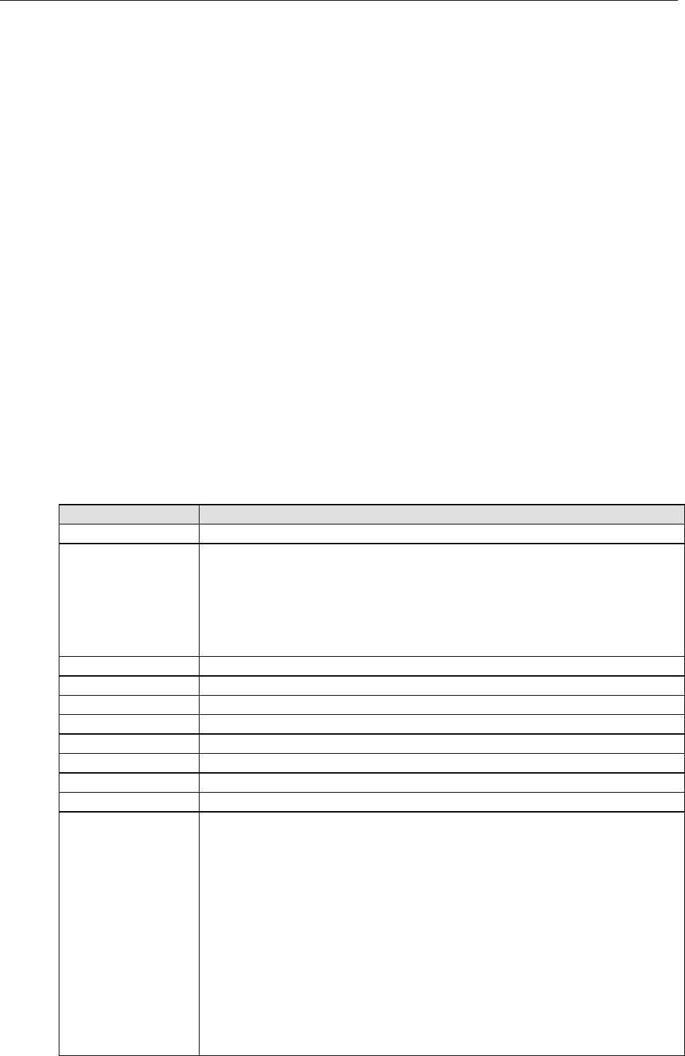
Specifications
1-2
Features
WAPN005
Specifications
ChipsetAtherosAR9344
BasebandProcessor
(BBP)
·DSSSwithDBPSK,DQPSK,CCK
·OFDMwithBPSK,QPSK,16QAM,64QAM
·802.11b:CCK@11/5.5Mbps,DQPSK@2Mbps,DBPSK@11Mbps
·802.11a/g:64QAM@54/48Mbps,16QAM@36/24Mbps,QPSK@18/12Mbps,
BPSK@9/6Mbps
·802.11n:64QAM@300MbpstoBPSK@6.5Mbps(multipleratessupported)
SecurityEngineWEP64,WEP128,WEP256,AES-CCM,TKIP,WPS
BusInterfaceMoxaproprietaryinterface
ConnectorBoard-to-board2x40pinsheader
PowerRequirement3.3V+/-10%
Dimensions60x60x12mm(2.36x2.36x0.47in)
Weight15g
OperatingTemperature-40to75℃
StorageTemperature:-40to85℃
Operatesin2.4and5
GHzfrequencybands.
US:
2.412to2.462GHz(11channels)
5.180to5.320GHz(8channels)
5.500to5.700GHz(8channels-excludes5.600to5.640GHz)
5.745to5.825GHz(5channels)
EU:
2.412to2.472GHz(13channels)
5.180to5.320GHz(8channels)
5.500to5.700GHz(11channels)
JP:
2.412to2.484GHz(14channels,DSSS)
5.180to5.320GHz(8channels)
5.500to5.700GHz(11channels)

WAPN005 User's Manual
Introduction
1-3

2
2.
Getting
Started
This
chapter
describes
the
hardware
introduction,
installation,
and
software
installation.
The
following
topics
are
covered
in
this
chapter:
Module
Layout
Hardware
Block
Diagram
Connector
Location
Board-to-board
Bus
Connector
PIN
Assignments
Hardware
Installation
Software
Installation
WAPN005 User's Manual
Getting Started
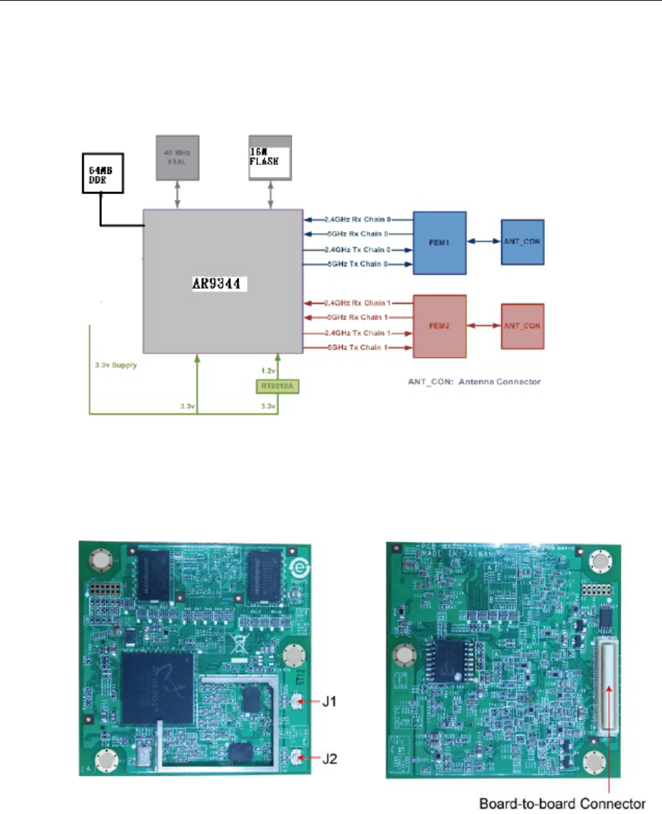
Hardware
Block
Diagram
RefertothefollowingfigurethehardwareblockdiagramoftheWAPN005.
Connector
Location
RefertothefollowingfiguresfortheconnectorlocationoftheWAPN005module.
2-2
WAPN005 User's Manual
Getting Started
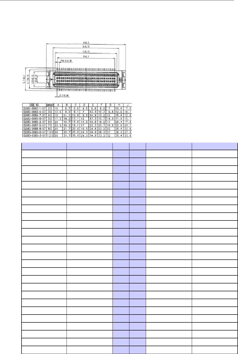
Board-to-board
Bus
Connector
PIN
Assignments
RefertothefollowingfiguresandtableforthePINassignmentoftheWAPN005moduleconnector.
2-4
Function
Connect
to
Pin
Pin
Function
Connect
to
3.3v
3.3v
1
2
GND
GND
3.3v
3.3v
3
4
GND
GND
3.3v
3.3v
5
6
ERXD3
PHY
RGMII
3.3v
3.3v
7
8
ERXD2
PHY
RGMII
3.3v
3.3v
9
10
ERXD1
PHY
RGMII
3.3v
3.3v
11
12
ERXD0
PHY
RGMII
3.3v
3.3v
13
14
GND
GND
GPIO
16
I2C_SCLK
15
16
GND
GND
GPIO
17
I2C_DATA
17
18
ETX_CLK
ETX_CLK
GND
GND
19
20
GND
GND
GPIO
21
POWER
2
21
22
GND
GND
GPIO
1
JP1
Debug
23
24
ETX_EN
ETX_EN
GND
GND
25
26
GND
GND
GPIO
4
S17_INT
27
28
GND
GND
GND
GND
29
30
ETXD3
PHY
RGMII
GPIO
0
I2C_INT0
31
32
ETXD2
PHY
RGMII
GND
GND
33
34
ETXD1
PHY
RGMII
GPIO
3
UR_DSR
35
36
ETXD0
PHY
RGMII
GPIO
9
UR_SIN
37
38
GND
GND
GPIO
10
UR_SOUT
39
40
GND
GND
GPIO
13
MDC
41
42
ERX_CLK
ERX_CLK
GPIO
14
MDIO
43
44
GND
GND
GPIO
20
POWER
1
45
46
GND
GND
GND
GND
47
48
ERX_EN
ERX_EN
GPIO
22
POWER
3
49
50
GND
GND
GND
GND
51
52
GND
GND
WAPN005 User's Manual
Getting Started
GPIO
2
UR_DTR
53
54
EMDC
GIGA
PHY
GND
GND
55
56
EMDIO
GIGA
PHY
GPIO
11
Reset
57
58
GND
GND
GND
GND
59
60
GND
GND
GPIO
12
LAN
10/100
61
62
TXP0
10/100
LAN
GND
GND
63
64
TXN0
10/100
LAN
GPIO
15
Reserved
65
66
GND
GND
GND
GND
67
68
RXP0
10/100
LAN
SYS_RST_L
GIGA
PHY
Reset
69
70
RXN0
10/100
LAN
AVDD18
Fast
Ethernet
bios
71
72
GND
GND
AVDD18
Fast
Ethernet
bios
73
74
GND
GND
AVDD18
Fast
Ethernet
bios
75
76
USB_DM
USB
port
GND
GND
77
78
USB_DP
USB
port
GND
GND
79
80
GND
GND
Hardware
Installation
Followthesestepstoinstallthehardwarecomponents.
1.AttachtheWLANantennatotheconnectorJ1.
2.AttachthesecondWLANantennatotheconnectorJ2.
3.ConnecttheWAPN005moduleonthesystemboardwiththeboard-to-boardconnectorandgentlypressthe
boardontothestack.Theboardshouldslideintothematchingbusconnectors.Donotattempttoforcethe
board,asthepinsmaybedistortedorbroken.
4.UsethescrewstofastentheWAPN005module.
5.Ifyourequirethepowerboard,installitabovetheWAPN005module.
6.Fastenallcomponentsonthenecessarychassis.
Software
Installation
Followthesestepstoinstallthesoftware.
1.Poweronthesystemboard.
2.ConnectsystemboardandPCwithanEthernetcable.
3.Openabrowserandtype:192.168.127.253toopenthesystemloginwebpage.
4.Loginthewebpagewithdefaultpassword:
root
toverifyallofthehardwarecomponentshavebeen
installedproperly.
2-5

A
A.
Regulatory
Statement
Approval
Federal
Communication
Commission
Interference
Statement
This
equipment
has
been
tested
and
found
to
comply
with
the
limits
for
a
Class
B
digital
device,
pursuant
to
Part
15
of
the
FCC
Rules.
These
limits
are
designed
to
provide
reasonable
protection
against
harmful
interference
in
a
residential
installation.
This
equipment
generates,
uses
and
can
radiate
radio
frequency
energy
and,
if
not
installed
and
used
in
accordance
with
the
instructions,
may
cause
harmful
interference
to
radio
communications.
However,
there
is
no
guarantee
that
interference
will
not
occur
in
a
particular
installation.
If
this
equipment
does
cause
harmful
interference
to
radio
or
television
reception,
which
can
be
determined
by
turning
the
equipment
off
and
on,
the
user
is
encouraged
to
try
to
correct
the
interference
by
one
of
the
following
measures:
-
Reorient
or
relocate
the
receiving
antenna.
-
Increase
the
separation
between
the
equipment
and
receiver.
-
Connect
the
equipment
into
an
outlet
on
a
circuit
different
from
that
to
which
the
receiver
is
connected.
-
Consult
the
dealer
or
an
experienced
radio/TV
technician
for
help.
FCC
Caution
To
assure
continued
compliance,
(example
-
use
only
shielded
interface
cables
when
connecting
to
computer
or
peripheral
devices)
any
changes
or
modifications
not
expressly
approved
by
the
party
responsible
for
compliance
could
void
the
user's
authority
to
operate
this
equipment.
This
device
complies
with
Part
15
of
the
FCC
Rules.
Operation
is
subject
to
the
following
two
conditions:
(1)
This
device
may
not
cause
harmful
interference,
and
(2)
This
device
must
accept
any
interference
received,
including
interference
that
may
cause
undesired
operation.
IMPORTANT
NOTE:
This
module
is
restricted
to
mobile
configuration.
To
comply
with
FCC
RF
exposure
compliance
requirements,
the
antenna
used
for
this
transmitter
must
be
installed
to
provide
a
separation
distance
of
at
least
20
cm
from
all
persons
and
must
not
be
co-located
or
operating
in
conjunction
with
any
other
antenna
or
transmitter.
This
transmitter
module
must
not
be
co-located
or
operating
in
conjunction
with
any
other
antenna
or
transmitter
CAUTION
Any
changes
or
modifications
not
expressly
approved
by
the
grantee
of
this
device
could
void
the
user's
authority
to
operate
the
equipment.
This
device
is
operation
in
5.15
–
5.25GHz
frequency
range,
then
restricted
in
indoor
use
only.
End
Product
Labeling
This
transmitter
module
is
authorized
only
for
use
in
device
where
the
antenna
may
be
installed
such
that
20cm
may
be
maintained
between
the
antenna
and
users.
The
final
end
product
must
be
labeled
in
a
visible
area
with
the
following:
"Contains
FCC
ID:
SLE-WAPN005
”

WAPN005 User's Manual
Regulatory Statement Approval
RF
Exposure
Warning
Thisequipmentmustbeinstalledandoperatedinaccordancewithprovidedinstructionsandtheantenna(s)
usedforthistransmittermustbeinstalledtoprovideaseparationdistanceofatleast20cmfromallpersons
andmustnotbeco-locatedoroperatinginconjunctionwithanyotherantennaortransmitter.End-usersand
installersmustbeprovidewithantennainstallationinstructionsandtransmitteroperatingconditionsfor
satisfyingRFexposurecompliance.
Information
for
the
OEMs
and
Integrators
Thefollowingstatementmustbeincludedwithallversionsofthisdocumentsuppliedtoan
OEMorintegrator,butshouldnotbedistributedtotheenduser.
1)ThisdeviceisintendedforOEMintegratorsonly.
2)PleaseseethefullGrantofEquipmentdocumentforotherrestrictions.
ThisradiotransmitterFCCID:SLE-WAPN005hasbeenapprovedbyFCCtooperatewiththeantennatypes
listedbelowwiththemaximumpermissiblegainandrequiredantennaimpedanceforeachantennatype
indicated.Antennatypesnotincludedinthislist,havingagaingreaterthanthemaximumgainindicatedfor
thattype,arestrictlyprohibitedforusewiththisdevice.
Antenna
List
Note
Thisisaspecificproductthatrequiresprofessionalinstallationandconfiguration,mustbeperformedbytrained
technicalengineerstoinstalltheantenna.ContactMoxaformoreinformation.
A-2
No.
Manufacturer
Part
No.
Peak
Gain
1KINSUNANT-WDB-0-2-BK(main/A)(aux/B)2.9dBiin2.4GHz
2.3dBiin5GHz
2KINSUNANT-WDB-ANM-0502(main/A)(aux/B)4.62dBiin2.4GHz
1.41dBiin5GHz