NETSCOUT Systems OPTIVIEW-XG Local Area Network Test and Diagnostic Test Equipment User Manual OptiView XG GSG
Fluke Networks Local Area Network Test and Diagnostic Test Equipment OptiView XG GSG
Contents
- 1. Updated User Manual
- 2. Users manual
Updated User Manual

OPTIVIEW XG
NETWORK ANALYSIS TABLET
Getting Started Guide
PN 3460305
June 2011, Rev. 2, 6/2011
© 2011 Fluke Corporation. All rights reserved. Printed in USA.
All product names are trademarks of their respective companies.
LIMITED WARRANTY & LIMITATION OF LIABILITY
Each Fluke Networks product is warranted to be free from defects in material and workmanship under normal use
and service. The warranty period for the mainframe is one year and begins on the date of purchase. Parts,
accessories, product repairs and services are warranted for 90 days, unless otherwise stated. Ni-Cad, Ni-MH and
Li-Ion batteries, cables or other peripherals are all considered parts or accessories. The warranty extends only to
the original buyer or end user customer of a Fluke Networks authorized reseller, and does not apply to any product
which, in Fluke Networks' opinion, has been misused, abused, altered, neglected, contaminated, or damaged by
accident or abnormal conditions of operation or handling. Fluke Networks warrants that software will operate
substantially in accordance with its functional specifications for 90 days and that it has been properly recorded on
non-defective media. Fluke Networks does not warrant that software will be error free or operate without
interruption.
Fluke Networks authorized resellers shall extend this warranty on new and unused products to end-user customers
only but have no authority to extend a greater or different warranty on behalf of Fluke Networks. Warranty support
is available only if product is purchased through a Fluke Networks authorized sales outlet or Buyer has paid the
applicable international price. Fluke Networks reserves the right to invoice Buyer for importation costs of repair/
replacement parts when product purchased in one country is submitted for repair in another country.
Fluke Networks warranty obligation is limited, at Fluke Networks option, to refund of the purchase price, free of
charge repair, or replacement of a defective product which is returned to a Fluke Networks authorized service
center within the warranty period.
To obtain warranty service, contact your nearest Fluke Networks authorized service center to obtain return
authorization information, then send the product to that service center, with a description of the difficulty, postage
and insurance prepaid (FOB destination). Fluke Networks assumes no risk for damage in transit. Following
warranty repair, the product will be returned to Buyer, transportation prepaid (FOB destination). If Fluke Networks
determines that failure was caused by neglect, misuse, contamination, alteration, accident or abnormal condition of
operation or handling, or normal wear and tear of mechanical components, Fluke Networks will provide an estimate
of repair costs and obtain authorization before commencing the work. Following repair, the product will be returned
to the Buyer transportation prepaid and the Buyer will be billed for the repair and return transportation charges
(FOB Shipping point).
THIS WARRANTY IS BUYER'S SOLE AND EXCLUSIVE REMEDY AND IS IN LIEU OF ALL OTHER
WARRANTIES, EXPRESS OR IMPLIED, INCLUDING BUT NOT LIMITED TO ANY IMPLIED WARRANTY OR
MERCHANTABILITY OR FITNESS FOR A PARTICULAR PURPOSE. FLUKE NETWORKS SHALL NOT BE
LIABLE FOR ANY SPECIAL, INDIRECT, INCIDENTAL OR CONSEQUENTIAL DAMAGES OR LOSSES,
INCLUDING LOSS OF DATA, ARISING FROM ANY CAUSE OR THEORY.
Since some countries or states do not allow limitation of the term of an implied warranty, or exclusion or limitation of
incidental or consequential damages, the limitations and exclusions of this warranty may not apply to every buyer. If
any provision of this Warranty is held invalid or unenforceable by a court or other decision-maker of competent
jurisdiction, such holding will not affect the validity or enforceability of any other provision.
4/04
Fluke Networks
PO Box 777
Everett, WA 98206-0777
USA
i
Table of Contents
Title Page
Safety Information ........................................................................................................................ 1
Symbols .......................................................................................................................................... 2
Introduction .................................................................................................................................. 3
Package Contents .......................................................................................................................... 4
Optional Accessories ..................................................................................................................... 6
Shipping Damage ................................................................................................................. 8
Registering the OptiView XG ....................................................................................................... 8
Getting Help .................................................................................................................................. 8
Contacting Fluke Networks .......................................................................................................... 8
Connectors, Controls, and Indicators ...........................................................................................9
Powering On ............................................................................................................................... 13
Sleep Mode .................................................................................................................................. 14
Powering-Off ............................................................................................................................... 15
Stylus ............................................................................................................................................ 16
Extending the Stand ................................................................................................................... 17
Connecting the OptiView XG to a Network .............................................................................. 18
Establishing a Wired or Fiber Connection ......................................................................... 18
Establishing a Wireless Connection ................................................................................... 20
Enabling the Wi-Fi Adapters .............................................................................................. 21
Configuring the OptiView XG for Use with Your Network ...................................................... 25
Context-Sensitive Help System ................................................................................................... 26
Operating the OptiView XG on Battery Power ......................................................................... 27
Battery Operation ............................................................................................................... 27
Charging the Batteries ....................................................................................................... 27
Power/Charge Indicator ...................................................................................................... 27
Displaying the Battery Charge Status Window ................................................................. 28
Battery Charge Indicators (on batteries) ........................................................................... 28
Replacing/Hot Swapping the Batteries .............................................................................. 29
Battery Life in Sleep or Shut down Modes ........................................................................ 30
Battery Care ........................................................................................................................ 30
Extending Battery Operating Time .................................................................................... 30
Using the Touchscreen, Stylus, Keyboard, and Mouse ............................................................. 32
Multi-Touch Screen Use and Care ...................................................................................... 32
Multi-Touch Screen Calibration ......................................................................................... 32
Touchscreen Features (Right-click, etc.) and Virtual Keyboard Settings ......................... 33
Virtual Keyboard ................................................................................................................. 34
Connecting External Devices ...................................................................................................... 35
Keyboard, Mouse, Flash Drive, Printer, and Other USB Devices ...................................... 35
External eSATA Hard Drive ................................................................................................ 35
External Antenna ................................................................................................................ 35

Table of Contents
ii
Power Connector ................................................................................................................ 36
VGA Port for External Monitor .......................................................................................... 36
Controlling the OptiView XG from a Remote Computer ......................................................... 37
Remote PC Requirements ................................................................................................... 37
Installing the Remote User Interface ................................................................................. 37
Using the Remote User Interface ....................................................................................... 38
Encrypting Data Over the Remote User Interface ............................................................ 39
Remote Connection Termination ...................................................................................... 41
Security ........................................................................................................................................ 41
Physical Security: Kensington Lock .................................................................................... 41
Controlling Access to the OptiView XG ............................................................................. 42
Removing and Replacing the Hard Drive .................................................................................. 45
Removing the Hard Drive ................................................................................................... 45
Replacing the Hard Drive ................................................................................................... 46
Cleaning ....................................................................................................................................... 46
Troubleshooting .......................................................................................................................... 47
Windows Restore Options .......................................................................................................... 48
Windows System Restore ................................................................................................... 48
Windows System Recovery ................................................................................................. 48
Specifications ............................................................................................................................... 53
Physical Specifications ........................................................................................................ 53
Environmental Specifications ............................................................................................. 53
Electrical Specifications ...................................................................................................... 54
Cables .................................................................................................................................. 55
Wireless Antennas .............................................................................................................. 55
Wireless Adapters 1 & 2 ...................................................................................................... 56
Supported Network Standards .......................................................................................... 57
Compliance Statements ...................................................................................................... 57
Federal Communication Commission and Industry Canada Interference Statement ..... 58
Exposure to RF Energy ........................................................................................................ 60
Europe-EU Declaration of Conformity .............................................................................. 61
Contacting Fluke Networks ........................................................................................................ 63

1
Safety Information
Safety Information
Warning
• With an optional SFP or SFP+ fiber adapter installed, the Product contains a Class 1 laser.
• Do not look directly into optical connectors while powered on. Some optical equipment emits
invisible radiation that can cause permanent damage to your eyes.
• Do not look directly into the laser with optical tools (for example, binoculars, telescopes,
microscopes). Optical tools can focus the laser and be dangerous to the eye.
• Use the Product only as specified or hazardous laser radiation exposure can occur.
• Carefully read all instructions and safety information before using the Product.
• Do not use the Product if it operates incorrectly.
• Use the Product only as specified, or the protection supplied by the Product can be
compromised.
• Do not operate the Product around explosive gas, vapor or in damp or wet environments.
• Do not expose batteries to fire.
• Do not short circuit or disassemble batteries.
• Do not expose batteries to temperatures above 70°C.
• Use charging procedures specified in manual.
• Use only Fluke Networks supplied charger and battery packs in the instrument.
• Batteries must be recycled or disposed of properly.
Caution
This equipment generates, uses, and can radiate radio frequency energy, and, if not installed and
used in accordance with its intended use, may cause interference to radio communications. This
device has been tested and found to comply with the limits for a Class A digital device pursuant
to Part 15 of the FCC rules, which are designed to provide reasonable protection against such
interference when operated in a commercial environment. Operation of the equipment in a
residential area is likely to cause interference, in which case the user, at his own expense, will be
required to take appropriate measures to correct the interference.
Caution
• Do not connect the Product to a telephone line or an ISDN line.
• Use the correct cables and connectors when connecting the Product to a network.
• Do not block or restrict the Product’s air intake or exhaust ports.

2
OptiView XG Network Analysis Tablet
Getting Started Guide
Symbols
The following symbols appear on the product or in the manual.
Table 1. Symbols
Not for connection to public telephone systems.
Please read manual for safety.
Shock hazard.
Class 1 laser product. Do not look into laser.
Complies with EN/IEC 60825-1:2007
Do not put products that contain circuit boards into waste containers. Refer to
local regulations for disposal procedures.
Recycle lithium-ion batteries.
Complies with European Union directives.
Complies with CAN/CSA-C22.2 no. 61010-1-04 Canadian standards, and
UL61010-1:2004 (US standards).
Meets Australia EMC requirements.
Conforms to FCC rules, parts15.107, 15.109.
Industry Canada, complies with Canadian safety standards.
Batteries: Useful life is approximately 5 years.
Year of battery manufacture is shown beneath symbol.
TUV Rheinland safety and EMC compliant.
3
Introduction
Introduction
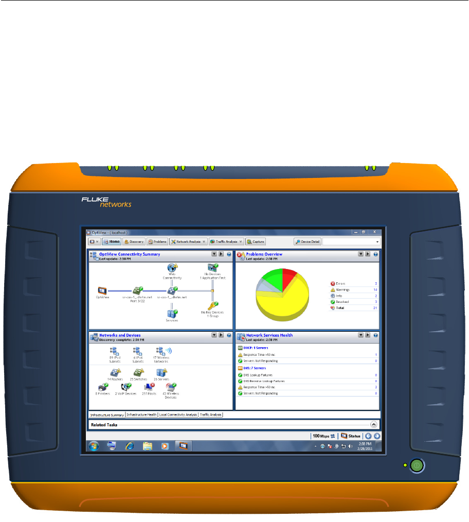
The OptiView XG Network Analysis Tablet provides 10/100/1000Mbps/10Gbps wired and 802.11
wireless network analysis anywhere in the network. The tablet enables users to monitor and
analyze key assets remotely from the desk and troubleshoot locally "on-the-wire." It's an all-in-
one portable network analysis tool designed to help network professionals save time resolving
performance problems that are impacting the end-user experience. The flexible user interface
allows for custom presentation of information and test results to meet specific needs. The
OptiView XG also provides accurate reporting and documentation of the network.
Figure 1. OptiView XG Network Analysis Tablet
O
PTI
V
IEW
N
ETWORK
A
NALYSIS
T
ABLET
XG
PORT A PORT C PORT D
PORT B Wi-Fi 2Wi-Fi 1
4
OptiView XG Network Analysis Tablet
Getting Started Guide
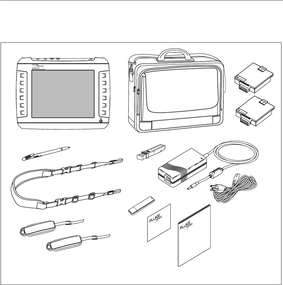
Package Contents
Verify that the following items are supplied with your OptiView XG Network Analysis Tablet.
GLZ20.EPS
Figure 2. Supplied Items
OptiView XG Soft Case
SFP Adapter
AC Adapter Power Cord
Shoulder Strap
Hand Strap
Batteries
Stylus
Getting Started
Flash Drive
Registration Card
Guide

5
Package Contents
Table 2. Supplied Items
Item Description Model Number
OptiView XG Network Analysis Tablet. —
1000BASE-SX SFP 1000BASE-SX SFP optical transceiver module (adapter), 850 nm,
50 and 62.5 micron multi-mode.
OPV-SFP-SX
Stylus Stylus for use on OptiView XG touchscreen. OPVXG-STYLUS
Batteries Set of two lithium-ion batteries with built-in charge indicators.
Provides approximately two hours of run time.
OPVXG-BATTERY
Hand and Shoulder
Straps
Attach to the OptiView XG for easy carrying. OPVXG-STRAPS
Soft Case Protective soft case. OPVXG-CCASE
AC Adapter Input: 90-264 VAC, 47-63 Hz, 2.0 A max
Output: 19 VDC, 4.74 A, 90 W.
Caution: For safe operation, use only the supplied AC
adapter.
OPVXG-PS
AC power cord Country-specific AC power cord (line cord). —
Getting Started
Guide
This document. —
Flash Drive Includes Remote User Interface software, Help System, and
Getting Started Guide in multiple languages, PDF format. —
Registration Card Fluke Networks can best serve you when you register online at
www.flukenetworks.com.
If you cannot register online, please fill out and return the
supplied registration card.
—
6
OptiView XG Network Analysis Tablet
Getting Started Guide
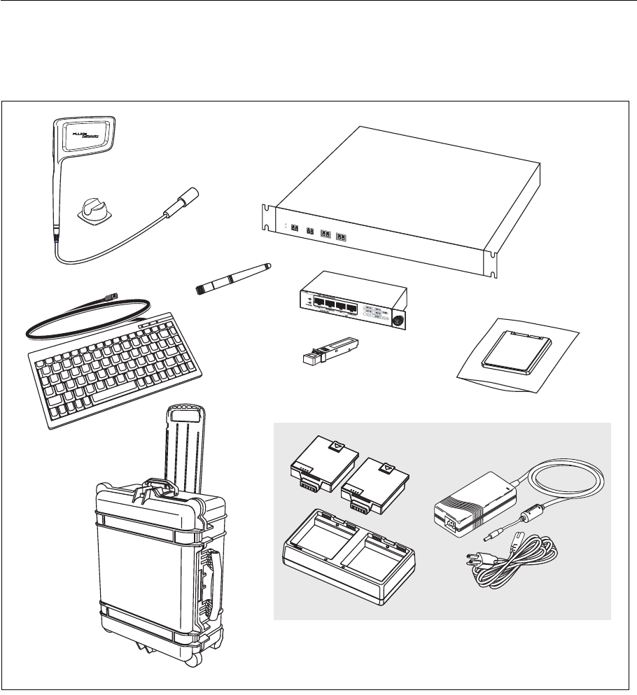
Optional Accessories
The following accessories were available when this manual was printed. For an updated list see
www.flukenetworks.com.
GLZ21.EPS
Figure 3. Optional Accessories
Esc F1 F1
F1 F1 F1 F1 F1 F1 F1
F1
F1 F1 F1 F1
F1
F1
!
1
@
2
#
3
$
4
%
5
Y&
7
I
OP
{{
Q
QWE
RTYUIOP
{{
A
Caps
Lock
S
F
DGHJKL:
;
“
‘
Enter
Enter
Z
Shift
X
V
CBNM<
,
>
.
?
/
?
/
POWER 1
POWER 2LINK
TAP 1 PORT 1P ORT 2
NETWORK PORTS MONITOR PORTS
AB
Directional Antenna
with Mounting
10 Gbps Fiber Tap
Hard Drive in
ESD protective bag
Battery Charger Bundle
Keyboard
Hard Case
1 Gbps
Copper Tap
SFP Adapter
Omnidirectional
Antenna
Hardware

7
Optional Accessories
1Use standard ESD protection practices when handling this item.
Table 3. Optional Accessories
Item Description Model Number
Directional Antenna Directional Antenna for use with AirMagnet WiFi Analyzer PRO and
Spectrum XT applications.
OPV-DIRECT-ANT
Omnidirectional
Antenna
Omnidirectional antenna for use with AirMagnet applications. OPV-OMNI-ANT
Keyboard Small-footprint USB keyboard for connection to OptiView XG. OPVS2-KB
Hard Case Hard-sided carrying case. OPVXG-HCASE
Removable Hard
Drive1
Removable hard drive, supplied in static-resistive bag. OPVXG-RHD
Tap, Fiber 10 Gbps in-line filtering fiber tap with two XFP any-to-any ports. FAXTAP1204SR-10G
Tap, Copper 1 Gbps in-line copper tap. Passive @ 10/100 Mbps, active @
1000 Mbps.
TAP-10/100/1000
Battery Charger
Bundle
Set of two battery packs, charging station, AC adapter, and line
cord.
OPVXG-BATT-KIT
10G Fiber SFP+ SR
adapter
10GBASE-SR SFP+ optical transceiver module (adapter), 850 nm
multi-mode.
OPVXG-SFP-PLUS-SR
10G Fiber SFP+ LR
adapter
10GBASE-LR SFP+ optical transceiver module (adapter), 1310 nm
single mode.
OPVXG-SFP-PLUS-LR
10G Fiber SFP+ LRM
adapter
10GBASE-LRM SFP+ optical transceiver module (adapter), 1310 nm
multi-mode.
OPVXG-SFP-PLUS-
LRM
1G Fiber SFP SX
adapter
1000BASE-SX SFP optical transceiver module (adapter), 850nm, 50
and 62.5 micron multi-mode.
OPV-SFP-SX
1G Fiber SFP LX
adapter
1000BASE-LX SFP optical transceiver module (adapter), 1300 nm,
10 micron single mode.
OPV-SFP-LX
1G Fiber SFP ZX
adapter
1000BASE-ZX SFP optical transceiver module (adapter), 1550 nm,
single mode.
OPV-SFP-ZX
100M Fiber SFP FX
adapter
100BASE-FX SFP optical transceiver module (adapter), 1310 nm. OPV-SFP-100FX
8
OptiView XG Network Analysis Tablet
Getting Started Guide
Shipping Damage
If shipping damage has occurred, call the carrier immediately and file a claim. Then contact Fluke Networks
(see page 8) to arrange repair or replacement.
Registering the OptiView XG
To register, go to http://www.flukenetworks.com/registration. If you do not already have an
account, select the Create Account button to proceed.
You can also register the OptiView XG by filling out the registration card and sending it to Fluke
Networks.
Registration provides the following benefits:
• Notification of software updates
• Three free telephone support incidences during the first 60 days of product ownership
• Access to the online Knowledge Base
• Web-based trouble ticket support
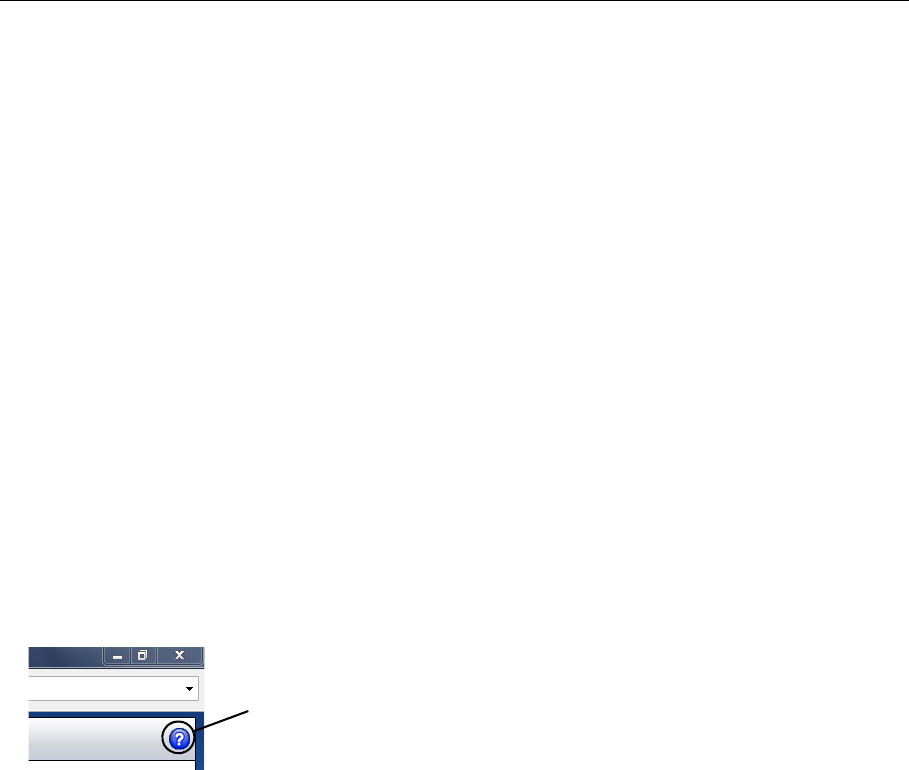
Getting Help
• For context-sensitive help, select the Help button (at the top of most OptiView XG screens)
• Go to http://www.flukenetworks.com/optiviewxg for downloads, demos, manuals, and more
• OptiView XG training courses may be offered at http://www.flukenetworks.com/training
Contacting Fluke Networks
Web: www.flukenetworks.com/contact
e-mail: support@flukenetworks.com
Phone: (USA) 1-800-283-5853
(Please see “Contacting Fluke Networks” on page 63 for international numbers.)
Help button
9
Connectors, Controls, and Indicators
Connectors, Controls, and Indicators
GLZ01.EPS
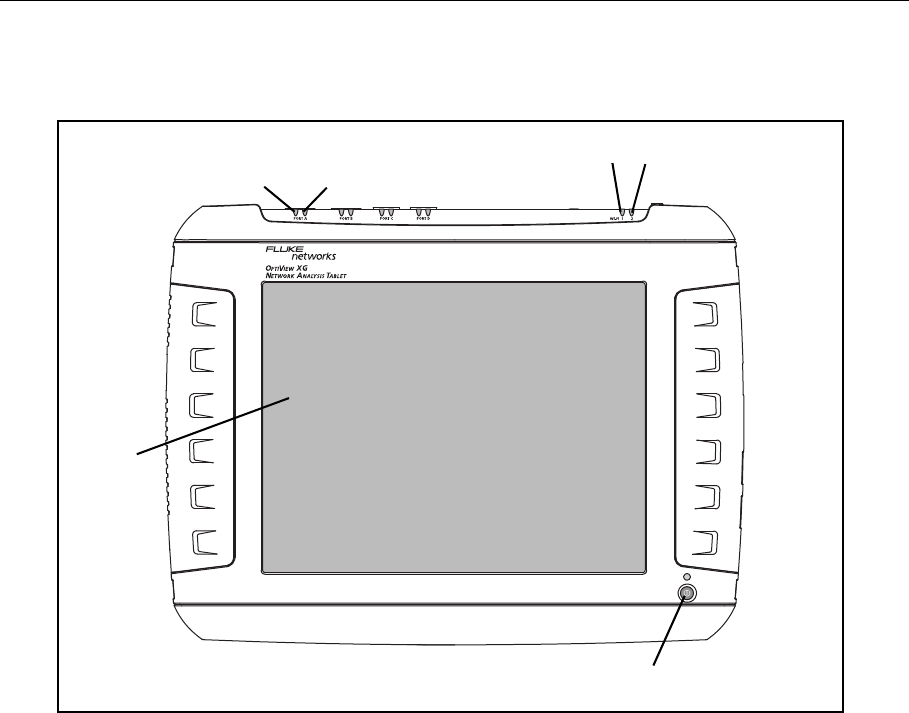
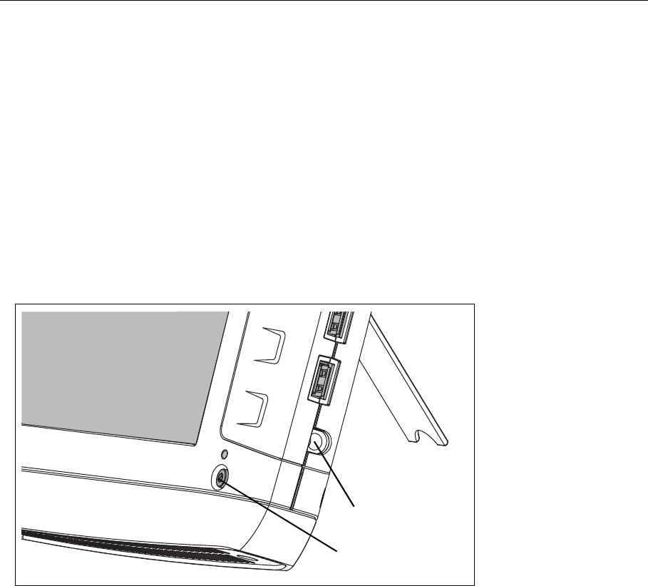
Figure 4. Front View
Link Speed Indicator, see page 19.
Link Utilization Indicator, see page 19.
Wi-Fi Indicators, see page 24.
Power Switch, see page 13.
Multi-Touch Display, see page 32.
Power Switch
Display
Link Speed
Indicator
Link Utilization
Indicator
Wi-Fi Indicators
10
OptiView XG Network Analysis Tablet
Getting Started Guide
GLZ02.EPS
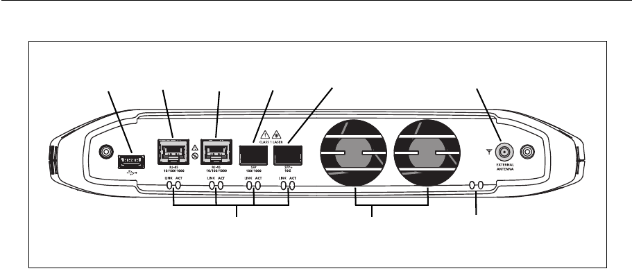
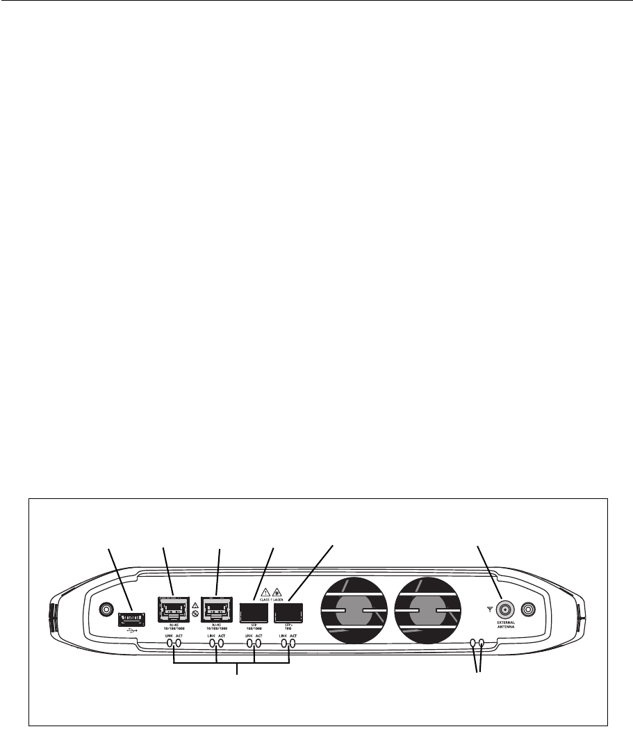
Figure 5. Top View
USB Port, see page 35.
Network Ports A, B, C, and D; see page 18.
External Antenna Connector, see page 35.
Link Speed Indicator, see page 19.
Link Utilization Indicator, see page 19.
Wi-Fi Indicators, see page 24.
<View of network connectors>
Port A Port B Port C Port DUSB Port External Antenna Connector
Link Speed and Utilization Indicators Wi-Fi Status Indicators Fans
11
Connectors, Controls, and Indicators
GLZ05.EPS
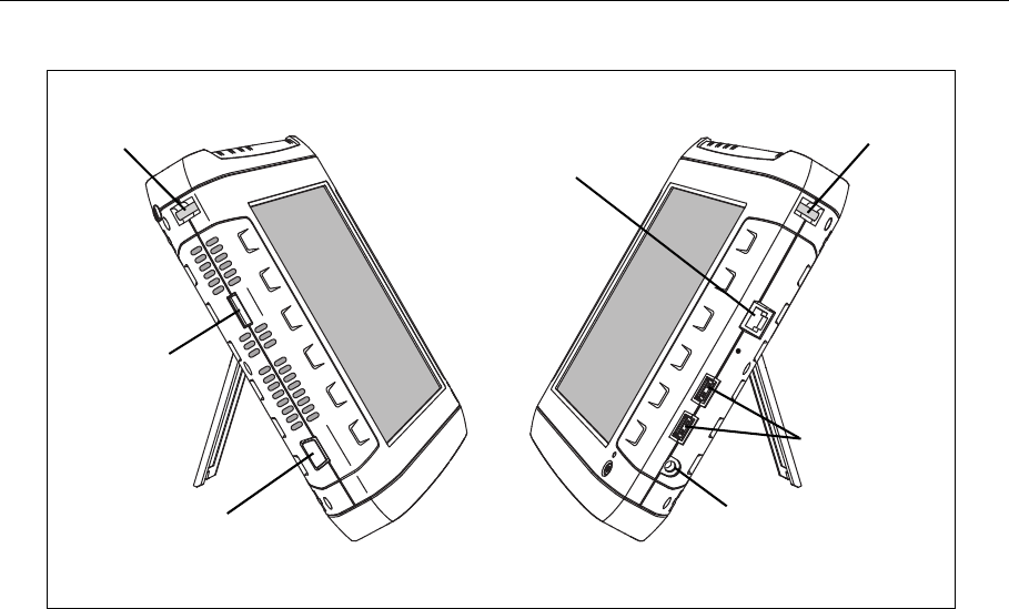
Figure 6. Left and Right Side Views
Carry strap post, for connecting carry strap.
eSATA connector, see page 35.
VGA Port, see page 36.
Management Port, see page 18.
USB Ports, see page 35.
Power Connector, see page 13.
VGA Port
eSATA
Carry Strap
Management
USB Ports
Power Connector
Carry Strap
Port
Post Post
Port
12
OptiView XG Network Analysis Tablet
Getting Started Guide
GLZ08.EPS
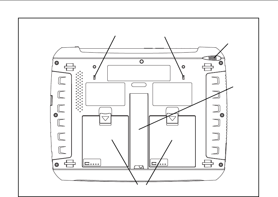
Figure 7. Rear View
Batteries, see page 27.
Stand, see page 17.
Stylus and Dock, see page 16.
Kensington Security Slot, see page 41.
Stylus Dock
Stand
Batteries
Kensington Security Slot/Attachment Point for Directional Antenna
Battery #2 Battery #1
13
Powering On
Powering On
1. Connect the AC adapter to a power source and to the OptiView XG Network Analysis Tablet.
See Figure 8, “Powering On” for the location of the power connector and power button.The
batteries are not fully charged before shipment due to transportation regulations.
2. Charge the batteries to full capacity before disconnecting the AC adapter. Charge time is
approximately 3 hours. Run time is approximately 2 hours with fully charged batteries.
• If the OptiView XG is powered-on, see the Battery Status Window (see page 28) to verify
that batteries are fully charged.
• If the OptiView XG is powered-off use the Battery Charge Status LED (see page 27) or the
Battery Charge Indicators on the batteries (see page 28) to verify that batteries are fully
charged.
3. Press the green On/Off button to power-on the OptiView XG.
GLZ04.EPS
Figure 8. Powering On
The OptiView XG will power-up. The following screens will be displayed during power up:
1. Blank screen.
2. Fluke Networks splash screen.
3. Windows 7 operating system startup screens.
4. Fluke Networks desktop background.
Power button
Power connector
14
OptiView XG Network Analysis Tablet
Getting Started Guide
5. The OptiView XG application.
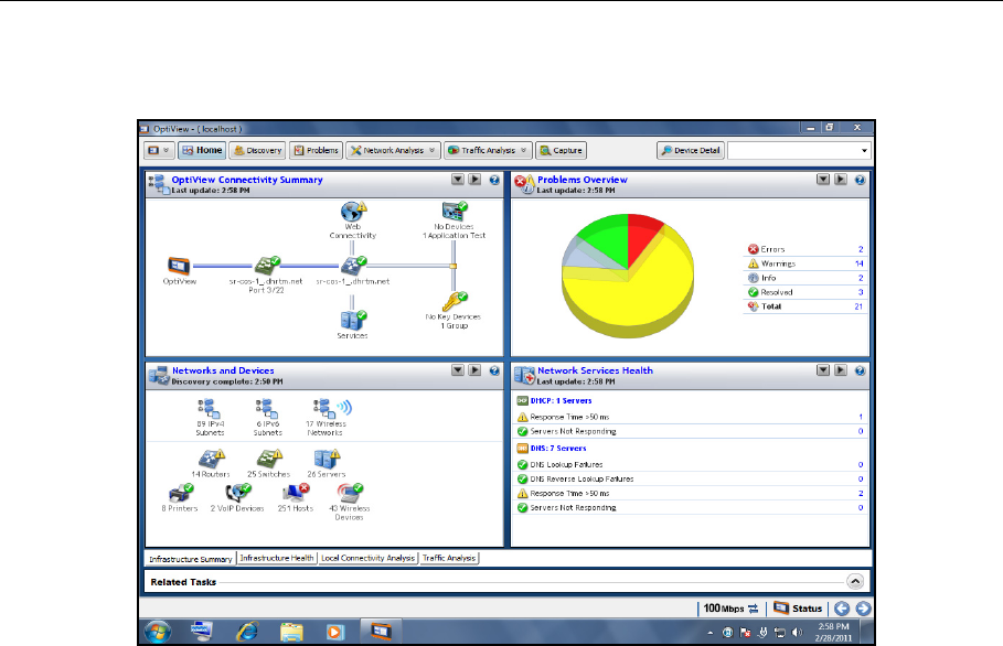
6. When power-on is complete, the default Home page is displayed.
Figure 9. OptiView XG Home Screen
For more information, see “Context-Sensitive Help System” on page 26.
Sleep Mode
In the factory-default configuration, when you press the OptiView’s power button the Windows
Sleep sequence is activated and the unit goes into a low power state. The Power/Charge LED
indicator behavior is described on page 27.
Settings that you configure in the OptiView Settings screens are retained through Sleep and
Shutdown cycles. Discovery and Traffic Analysis data are not retained.
To resume from Sleep mode, press the power button.
Two fully-charged batteries will last approximately 36 hours when the OptiView XG is in Sleep
mode.

15
Powering-Off
Powering-Off
If you plan to leave the OptiView XG in Sleep mode while unplugged from the AC adapter for an
extended period, power-off the OptiView XG to avoid fully discharging the batteries.
When the OptiView XG has been powered-off (using Windows Shut down), battery life is
determined by the internal discharge rate of the lithium-ion batteries, which is approximately 5-
10% per month.
To power-off the OptiView XG:
1. Select the Windows 7 button.
2. Select the Shutdown button.
The Windows 7 Shutdown sequence will be activated, and the OptiView XG will power-off.
Settings that you configure in the OptiView Settings screens are retained through Sleep and
Shutdown cycles. Discovery and Traffic Analysis data are not retained.
See also: “Battery Life in Sleep or Shut down Modes” on page 30.
16
OptiView XG Network Analysis Tablet
Getting Started Guide
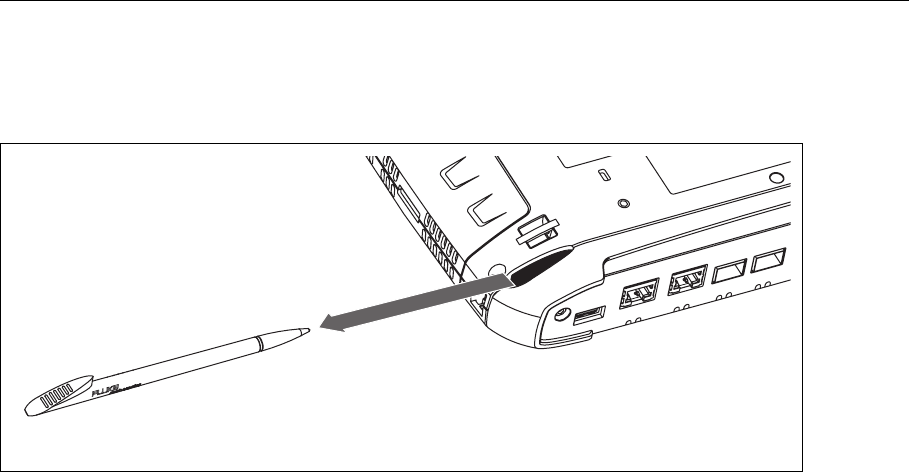
Stylus
The stylus is docked in the upper right corner of the rear panel. Slide it out to use it; slide it back in
for storage.
GLZ07.EPS
Figure 10. Stylus and Dock
The multi-touch screen is designed for use with a stylus. However, you can also use your fingertip.
Your fingernail or a stylus provide more accurate control than the pad of your fingertip. Use of
sharp objects or excessive pressure on the multi-touch screen may cause permanent damage.
See also: “Multi-Touch Screen Use and Care” on page 32.
17
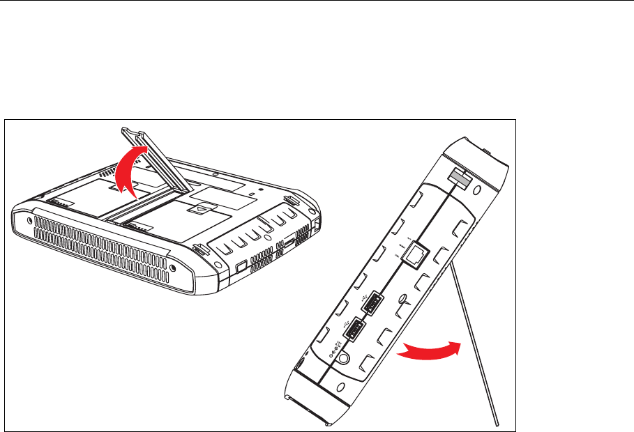
Extending the Stand
Extending the Stand
The stand is a convenient feature for desktop use. To extend the stand, pull at the recessed
portion located at the bottom of the stand. To retract the stand, push it back in until it snaps in
place.
GLZ03.EPS
Figure 11. Extending the Stand
18
OptiView XG Network Analysis Tablet
Getting Started Guide
Connecting the OptiView XG to a Network
You can connect the OptiView XG to a network via network ports A, B, C, or D, or via the built-in
wireless adapters.
The OptiView XG’s management port can be used for remote control of the analyzer (from a
separate network). This lets you control the analyzer from a management network while using
the OptiView XG to test a production network.
Establishing a Wired or Fiber Connection
Connect an appropriate cable from one of the OptiView XG’s network ports to the network that
you want to test. The OptiView XG will find the active network interface and obtain an IP address.
Then it will begin discovering the network.
Network Ports
The OptiView XG has the following network ports:
• Port A: RJ45 Ethernet connector, 10/100/1000 Mbps
• Port B: RJ45 Ethernet connector, 10/100/1000 Mbps
• Port C: 100/1000 Mbps Ethernet over fiber on standard SFP socket
• Port D: 10 Gbps Ethernet over fiber on standard SFP+ socket
• Management Port: RJ45 Ethernet connector, 10/100/1000 Mbps
GLZ02.EPS
Figure 12. OptiView XG Network Ports
<View of network connectors>
Port A Port B Port C Port DUSB Port External Antenna Connector
Link Speed and Utilization Indicators Wi-Fi Status Indicators

19
Connecting the OptiView XG to a Network
Caution
To prevent equipment damage, do not connect the OptiView XG Port A or Port B to a telephone
line or an ISDN line.
Link Speed and Utilization Indicators
There are two link status indicators for each network port: Link Speed (on the left) and Utilization
(on the right).
Installing/Removing the SFP or SFP+ Fiber Adapter (Transceiver)
To install an SFP or SFP+ Fiber adapter, remove the protective cap from the adapter and slide the
adapter into Port C or Port D. To remove, gently pull the SFP’s bail. If the SFP has retention tabs,
press and hold the tabs on the sides of the adapter and pull it from the fiber port.
A list of supported SFP and SFP+ modules is given in the specifications on page 54. See
www.flukenetworks.com for a complete list of supported SFP and SFP+ modules.
Table 4. Network Port Link Speed Indicator
Color Link Speed
Green 10 Mbps
Blue 100 Mbps
White 1000 Mbps
Magenta 10 Gbps
Table 5. Network Port Link Utilization Indicator
Color Link Utilization
Flashing Green 0% - 9%
Green 10% - 50%
Yellow 51% - 80%
Red 81% - 100%
20
OptiView XG Network Analysis Tablet
Getting Started Guide
Establishing a Wireless Connection
OptiView XG Wireless Capabilities
Wireless capabilities are an option at time of purchase, or may be enabled after purchase in
certain circumstances. If you purchased wireless capability and you reside in a country for which RF
certification has been received, the Wi-Fi adapters were enabled at the factory prior to shipment.
The OptiView XG Network Analysis Tablet includes internal wireless adapters and a spectrum
analyzer. They are available to the OptiView XG application and Fluke Networks AirMagnet
mobility applications for wireless network access and wireless LAN analysis and troubleshooting.
The OptiView XG application can use the Wi-Fi adapter for network access. Once connected, you
can analyze and troubleshoot the LAN.
The Fluke Networks AirMagnet mobility product suite uses the Wi-Fi adapters and spectrum
analyzer for comprehensive 802.11 and RF interference analysis as well as for site survey projects.
The OptiView XG tablet includes two Wi-Fi adapters: Wi-Fi 1 is for general use. Wi-Fi 2 and the
spectrum analyzer are reserved for use by Fluke Networks AirMagnet applications.
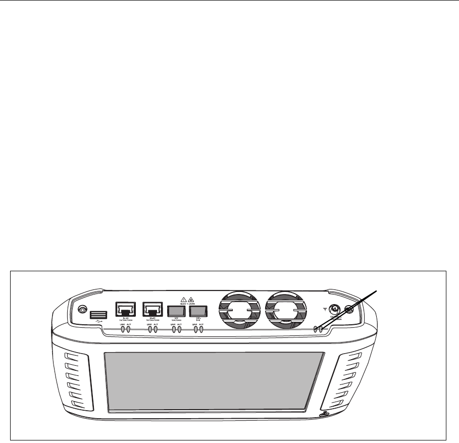
GLZ22.EPS
Figure 13. Wi-Fi Indicators
Wi-Fi Indicators
21
Connecting the OptiView XG to a Network
Enabling the Wi-Fi Adapters
If Fluke Networks received approval to enable the Wi-Fi adapters for use in your country before
your OptiView XG was shipped to you, and you purchased a model with wireless capabilities, the
Wi-Fi adapters are already enabled.
If Fluke Networks received approval to enable the Wi-Fi adapters for use in your country after
your OptiView XG was shipped to you and you purchased a model with wireless capabilities, you
can enable your Wi-Fi adapters by contacting your Fluke sales representative and obtaining a
power control key free-of-charge. Additionally, if you purchase AirMagnet applications a card will
be included. The card explains the procedure for obtaining the software license to enable the
Wi-Fi adapters.
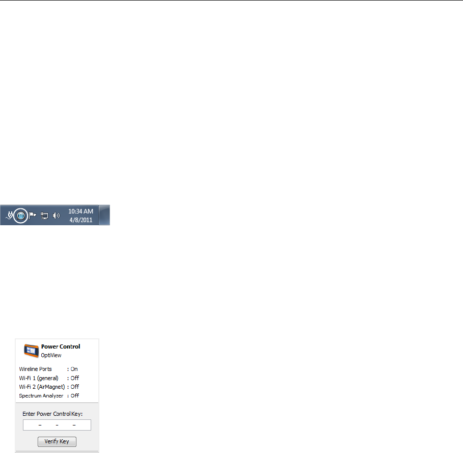
To determine whether the Wi-Fi adapters are enabled and powered on, select the OptiView
Power Control icon in the system tray.
Wi-Fi Adapters Not Enabled
If the Wi-Fi adapters have not been enabled, a dialog will be displayed as shown below. To enable
the wireless capabilities, enter a power control key.
• If Fluke Networks receives approval to enable Wi-Fi adapters in your country after you
purchase the OptiView XG, you can call Fluke Networks Technical Assistance Center to obtain a
power control key free-of-charge. Please see “Contacting Fluke Networks” on page 8.
22
OptiView XG Network Analysis Tablet
Getting Started Guide
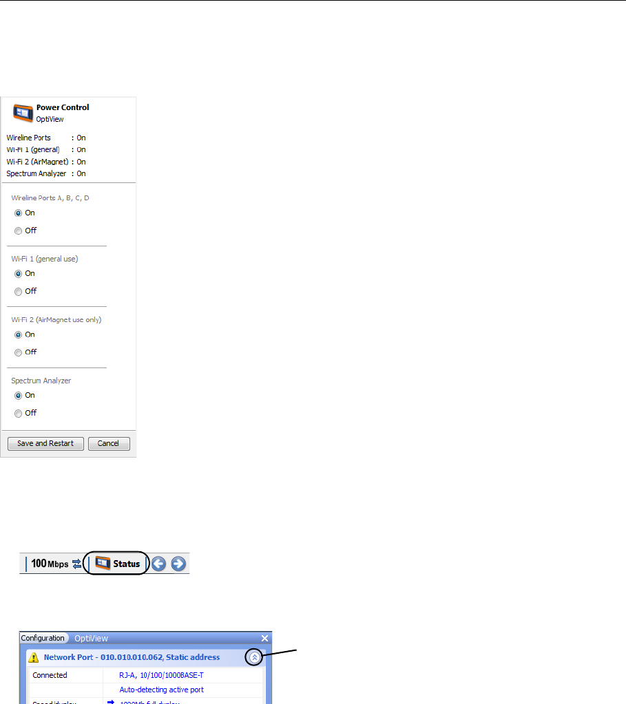
Wi-Fi Adapters Enabled
If the Wi-Fi adapters are enabled, the OptiView Power Control application will open as shown
below. Use the application to manage power for the adapters you want to use.
Setting Up a Wi-Fi Profile and Security
1. Select the Status button, which is located at the bottom of the screen. The configuration panel
will open.
2. Collapse the Network Port section and expand the Wireless Port section using the arrows at the
right.
The Wi-Fi adapters and the spectrum analyzer consume
small amounts of power, so it’s fine to leave them powered-on
even when operating on battery power.
Select the “Save and Restart” button to reboot the system and
make the changes effective.
Expand/collapse arrow
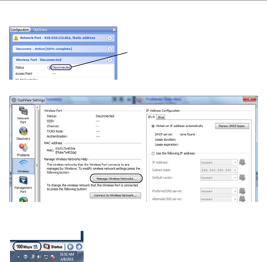
23
Connecting the OptiView XG to a Network
3. Select the word “Disconnected.” The OptiView Settings screen will be displayed, with the
Wireless icon highlighted at the left edge of the screen.
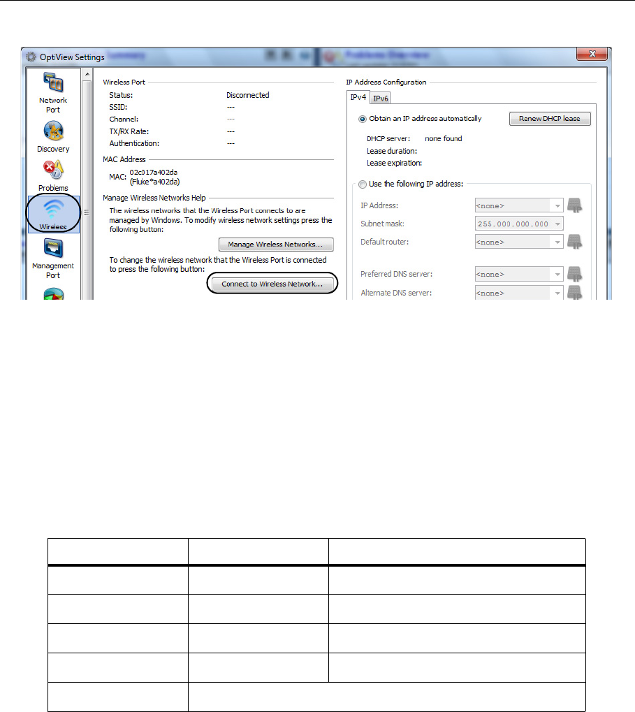
4. Select the Manage Wireless Networks button and follow the Windows 7 prompts.
Connecting to a Wireless Network
1. Select the Link Status button.
2. Select the Wireless button (which is located at the left side of the screen).
If the wireless adapters have not been enabled,
this will say “Disabled.”
24
OptiView XG Network Analysis Tablet
Getting Started Guide
3. Select the Connect to Wireless Network... button.
4. Select the desired network and follow the Windows 7 prompts.
The OptiView XG will connect to networks based on the profile preferences you create. View and
manage your wireless network connections by selecting the Manage Wireless Networks... button
shown in step 3.
Wi-Fi Indicators
Each of the two Wi-Fi adapters has a single link status indicator. The LED illuminates when the Wi-
Fi adapter is in use. The LED’s color indicates the link speed (or that the Wi-Fi adapter is in use by
an AirMagnet application). The LED flashes to indicate traffic is present on the link.
Table 6. Wi-Fi Indicator
Color Link Speed Standard
Green up to 11 Mbps 802.11b
Blue up to 54 Mbps 802.11a/g
White up to 300 Mbps 802.11n, with one or two spatial streams
Magenta 450 Mbps or more 802.11n, with three spatial streams (3x3)
Amber Wi-Fi adapter is in use by an AirMagnet application
25
Configuring the OptiView XG for Use with Your Network
Configuring the OptiView XG for Use with Your Network
1. If your network uses a MAC access list, you will need to add the OptiView XG’s MAC addresses
to the list. See the OptiView XG online help for more information.
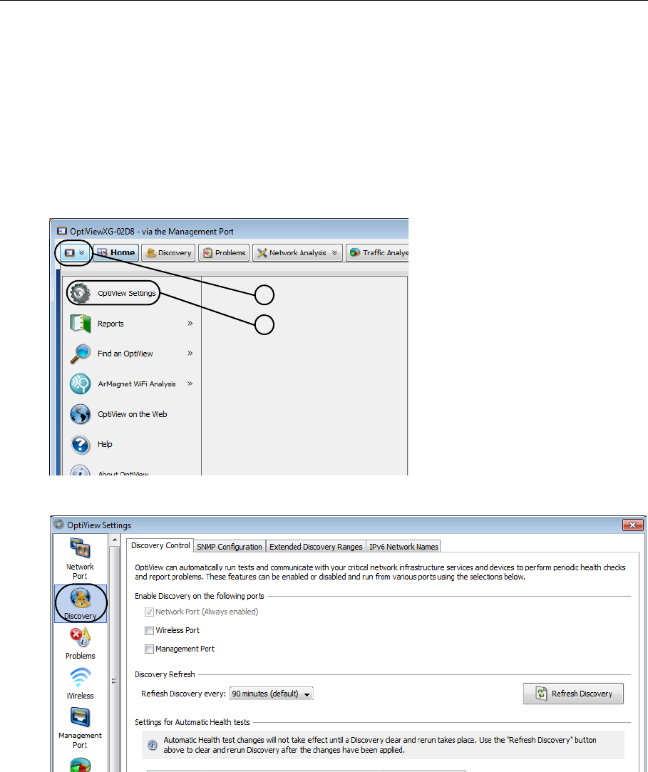
2. Configure SNMP community strings and/or credentials to allow the OptiView XG to fully
discover and analyze your network.
a. Select the top left OptiView button.
b. Select the OptiView Settings button.
c. Select the Discovery button.
a
b

26
OptiView XG Network Analysis Tablet
Getting Started Guide
d. Select the SNMP Configuration tab.
e. Add SNMP v1 and v2 community strings and/or add SNMP v3 credentials. Select the Help
button on the screen for more information.
3. Select the Extended Discovery Ranges tab to enable discovery of networks beyond the
broadcast domain (off-net networks). Select the Help button on the OptiView Settings screen
for more information.
Context-Sensitive Help System
Select the blue question mark to show help for the current screen.
Show Help for the current screen

27
Operating the OptiView XG on Battery Power
Operating the OptiView XG on Battery Power
Battery Operation
The OptiView XG Network Analysis Tablet has two lithium-ion batteries. The batteries are
installed into the back of the OptiView XG.
The OptiView XG will run approximately 2 hours using fully-charged batteries. You can hot-swap
spare batteries (one at a time if the AC adapter is not connected) to extend run-time.
Charging the Batteries
Before running the OptiView XG Network Analysis Tablet on batteries, connect the AC adapter to
the OptiView XG and charge the batteries. Charge time is approximately 3 hours.
Power/Charge Indicator
The LED next to the OptiView XG power button indicates the power on/off state and the battery
charge status.
Table 7. Power/Charge Indicator
LED Color LED State Description
Green On The OptiView XG is powered-on. Use the battery status window to
determine battery charge state. See instructions on page 28.
Yellow Flashing The OptiView XG is in sleep mode or powered-off.
The AC adapter is connected, and the batteries are charging.
Yellow On The OptiView XG is in sleep mode or powered-off.
If the AC adapter is connected, the batteries are fully charged.
Off Off The OptiView XG is powered-off (shutdown, not in sleep state) and the AC
adapter is disconnected.
28
OptiView XG Network Analysis Tablet
Getting Started Guide
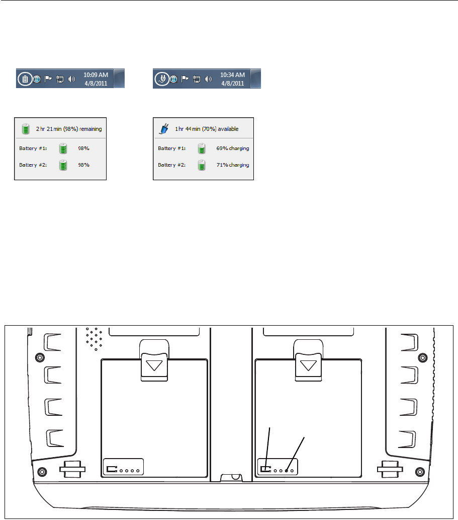
Displaying the Battery Charge Status Window
1. The battery status icon is located in the Windows system tray. It appears as a battery, a
charging battery, or an electrical plug. Select the icon to open the battery status window.
2. The estimated battery capacity is displayed.
3. Touch (or click) the screen outside the battery status window to close the battery status
window.
Battery Charge Indicators (on batteries)
The four LEDs on the back of each battery indicate the battery’s approximate charge. Press and
release the test button. Each illuminated LED indicates an additional 25% of available charge.
When the battery’s charge level is less than 10%, the left-most LED flashes.
GLZ24.EPS
Figure 14. Battery Charge Indicators
or
Running on battery
power.
Running on AC
power.
Press test
button View charge
indicators
Battery #2 Battery #1
29
Operating the OptiView XG on Battery Power
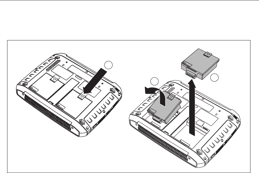
Replacing/Hot Swapping the Batteries
To remove a battery, (1) press the release clip and (2) pivot the battery out from the OptiView XG
case. To replace, pivot the battery in and press until it snaps into place.
GLZ06.EPS
Figure 15. Battery Removal and Replacement
When the AC power adapter is not connected, the OptiView XG is powered by whichever battery
contains the most charge. When the batteries have equal amounts of charge, the OptiView XG is
powered by both batteries.
The batteries can be hot-swapped. Replacing one battery will not interrupt the OptiView XG’s
operation as long as the other battery is capable of powering the OptiView XG.
An optional battery kit is available (see page 5). It contains two batteries, a charging station, and
an AC adapter for powering the charging station.
<graphic of battery removal>
1
2
3

30
OptiView XG Network Analysis Tablet
Getting Started Guide
Battery Life in Sleep or Shut down Modes
Two fully-charged batteries will last approximately 36 hours when the OptiView XG is in Sleep
mode.
If you plan to leave the OptiView XG in Sleep mode while unplugged from the AC adapter for an
extended period, power-off the OptiView XG to avoid fully discharging the batteries.
When the OptiView XG has been powered-off (using Windows Shut down), battery life is
determined by the internal discharge rate of the lithium-ion batteries, which is approximately 5-
10% per month.
Battery Care
To maximize the life of lithium-ion batteries, avoid frequent full discharges. Partial discharges
with frequent recharges will make the batteries last longer. Lithium-ion battery technology does
not suffer from the “memory effect,” so recharge the batteries whenever it’s convenient. Avoid
storing the batteries in a hot environment. For optimal long-term storage, store at about 50%
charge, in a cool place.
Extending Battery Operating Time
In its default configuration, the OptiView XG will operate for approximately two hours with fully-
charged batteries.
When only using the wireless adapters to connect to the network (not using Network Ports A, B,
C, or D) you can approximately double operating time by switching off power to the network
ports. You may want to do this when using the following (optional) applications for an extended
period of time for field operations:
• AirMagnet WiFi Analyzer PRO
• AirMagnet Spectrum XT
• AirMagnet Survey PRO
To Switch Off Power to Network Ports A, B, C, and D
1. Select the OptiView Power Control icon from the System Tray.
31
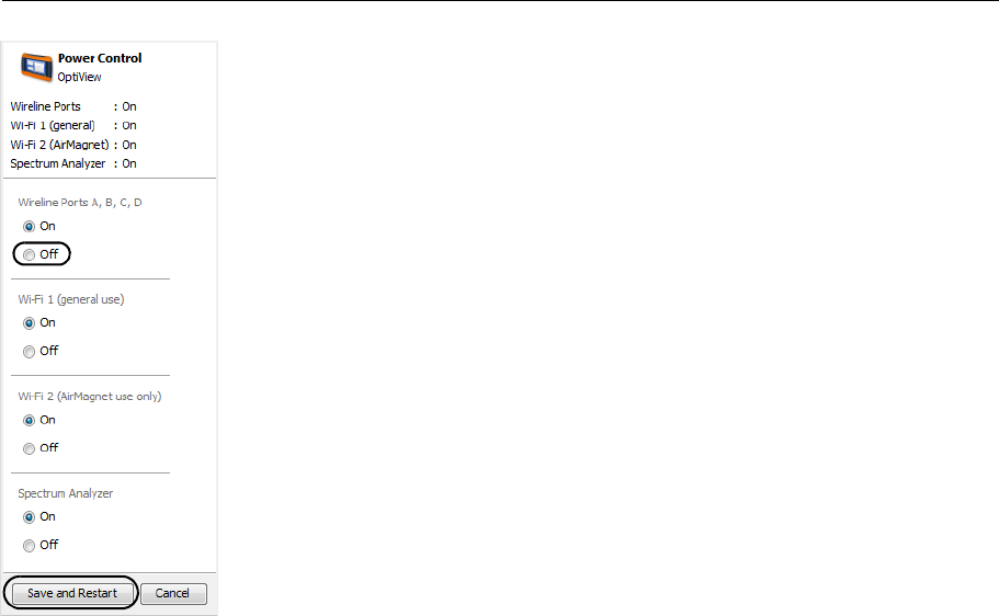
Operating the OptiView XG on Battery Power
The OptiView Power Control screen will appear, as shown.
2. Switch off Wireline Ports A, B, C, and D. This will approximately double
battery operation time.
3.The system must reboot to make the change. Select the Save and Restart
button.
Note
Remember to switch on Wireline Ports A, B, C, and D before attempting to use the Network Ports!

32
OptiView XG Network Analysis Tablet
Getting Started Guide
Using the Touchscreen, Stylus, Keyboard, and Mouse
Multi-Touch Screen Use and Care
The Multi-Touch Screen supports Windows 7 multi-touch gestures such as Flicks and right-click.
Clean the touchscreen using a soft cloth that has been moistened with mild detergent. Do not
spray liquid directly on the touchscreen because the liquid could seep into the OptiView XG
housing. Do not use harsh cleaners on the touchscreen.
See also: “Stylus” on page 16.
Multi-Touch Screen Calibration
The OptiView XG uses a standard Windows 7 touchscreen driver. To calibrate the touchscreen:
1. Select the Windows button (in the lower left corner of the display).
2. Select Control Panel.
3. Select View by: Small Icons. This selector is in the upper right area of the screen.
4. Select Tablet PC Settings.
5. In the Tablet PC Settings window, select the Calibrate button.
6. Follow the prompts.

33
Using the Touchscreen, Stylus, Keyboard, and Mouse
Touchscreen Features (Right-click, etc.) and Virtual Keyboard Settings
You can customize certain tablet PC features in Windows 7, including “Pen and Touch” and the
“Input Panel.” For example, you can adjust the amount of time you need to touch and hold a
point on the screen in order to perform a right-click. The right-click is performed when the touch
point is circumscribed.
1. Select the Windows button (in the lower left corner of the display).
2. Select Control Panel.
3. (Ensure View by: Category is selected in the upper right area of the screen.)
4. Select Tablet PC Settings.
5. Select the tab labeled Other.
6. Use the links to customize Pen and Touch and Virtual Keyboard (also called Input Panel)
settings.
34
OptiView XG Network Analysis Tablet
Getting Started Guide
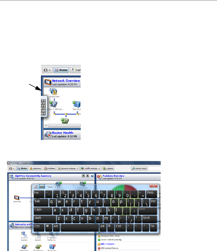
Virtual Keyboard
The virtual keyboard lets you type without a hardware keyboard. This is convenient when you are
on-site with the OptiView XG and a hardware keyboard is not connected.
To Use the Virtual Keyboard
1. Touch the left edge of the screen to reveal the edge of the virtual keyboard. Note that you can
drag the minimized keyboard up or down if it’s in your way.
2. When the edge of the keyboard appears, touch it again and it will come into full view. Touch
the keys to type. If desired, you can drag the keyboard to a different location on the screen.
3. After use, select the X to close the keyboard.
Touch edge
of window
to display
edge of
virtual
keyboard.

35
Connecting External Devices
Connecting External Devices
Keyboard, Mouse, Flash Drive, Printer, and Other USB Devices
You can connect an external keyboard, mouse, flash drive, hard drive, or printer to the OptiView
XG’s USB ports. Windows 7 will automatically recognize the devices and make them ready to use.
See page 10 and page 11 for the locations of the USB ports.
External eSATA Hard Drive
You can connect an external eSATA drive using a shielded cable with a length of one-half meter
or less. Restart Windows or use Control Panel→Device Manager→ Action→Scan for Hardware
Changes to cause Windows to recognize the drive. Note that the eSATA connector does not
supply power. An external power supply must power the eSATA drive. See page 11 for the
location of the eSATA port.
External Antenna
The OptiView XG normally uses its internal antennas. When using AirMagnet applications (e.g. for
locating rogues or performing spectrum analysis) you can attach and switch to an external
antenna. See page 18 for the location of the external antenna connector.
The optional omni-directional antenna offers better scanning sensitivity when using AirMagnet
Spectrum XT.
The optional directional antenna can be used in conjunction with AirMagnet Wi-Fi Analyzer PRO
and Spectrum XT applications for increasing signal sensitivity when locating devices.
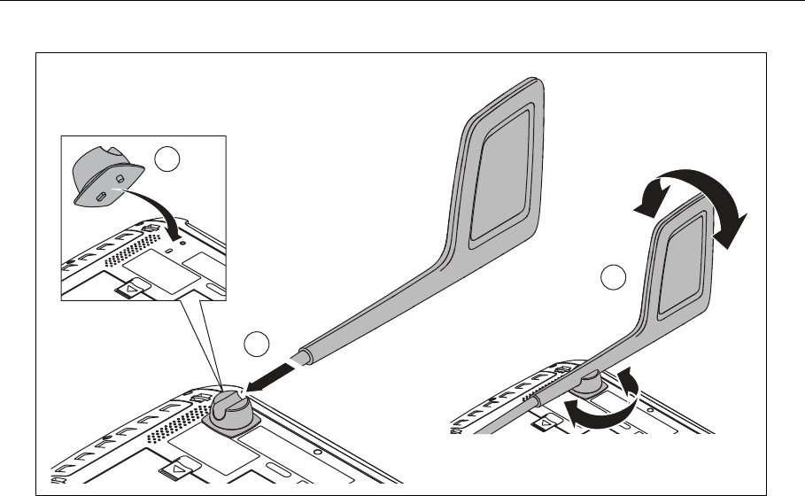
The directional antenna can be attached to the OptiView XG as shown in Figure 16, “Attaching
and Swiveling the Directional Antenna.”
36
OptiView XG Network Analysis Tablet
Getting Started Guide
GLZ23.EPS
Figure 16. Attaching and Swiveling the Directional Antenna
Power Connector
Connect only the supplied AC adapter to the power connector. Connection of any other power
source may damage the OptiView XG. See page 13 for the location of the power connector.
VGA Port for External Monitor
You can connect an external monitor or projector to the VGA port. When connecting to a
projector, go to the Windows 7 Control Panel and select Connect to a projector under the
Hardware and Sound heading. See page 11 for the location of the VGA port.
1
2
3

37
Controlling the OptiView XG from a Remote Computer
Controlling the OptiView XG from a Remote Computer
The Remote User Interface application lets you initiate remote sessions with OptiView units over a
TCP/IP connection. The software includes a browser that helps you easily find OptiView units and
initiate remote sessions.
Remote PC Requirements
Operating Systems:
• Windows XP Professional with SP3
• Windows 7 Professional with SP1, 32 bit and 64 bit
Operating System Languages:
• English, German, Japanese, Simplified Chinese
Installing the Remote User Interface
The remote user interface software may be installed from the supplied OptiView Resource flash
drive, or from the OptiView XG's web server home page.
Install from Flash Drive
To install from the flash drive, insert the flash drive in the remote PC’s USB port and follow the
prompts. If autorun is disabled, execute the Launch.exe file in the flash drive’s root directory.
Install from the OptiView XG’s Home Page
To view the OptiView XG's Home page, enter the OptiView XG's IP address in your PC's web
browser. Then select the Install Remote UI button.
38
OptiView XG Network Analysis Tablet
Getting Started Guide
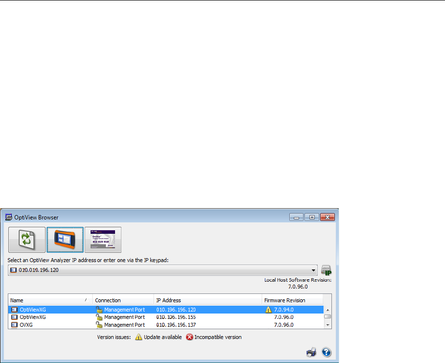
Using the Remote User Interface
Launch OptiView Browser
The first step in using the Remote User Interface is to launch the OptiView Browser. Double-click
the desktop icon or select it from the Windows Program Menu. It is in the Fluke Networks
program group. The OptiView Browser will launch, and a list of the analyzers in the local network
will be displayed.
Initiate a Remote Session
To initiate a remote session with an OptiView, double-click it in the search results window.
To see an OptiView that is not in the broadcast domain, enter the IP address of the unit in the
search bar of the OptiView Browser.
Once you’ve established a connection, you can close the OptiView Browser window if desired. This
will not terminate the remote session.

39
Controlling the OptiView XG from a Remote Computer
Encrypting Data Over the Remote User Interface
A computer can initiate a remote session with an OptiView (see page 37). Data sent to and from
the remote analyzer can be encrypted. The OptiView XG uses the Advanced Encryption Standard
(AES) 128 bit encryption algorithm. The encryption key can be entered in Hex or ASCII. ASCII is
provided for ease of remembering the encryption key. An encryption key containing less than 128
bits (16 ASCII characters) will be padded with 0's.
When an encryption key has been set, each user attempting to open a remote UI session with the
OptiView XG will be prompted to enter the encryption key. When a remote encrypted session has
been established via a remote PC, the encryption key will be remembered on the remote PC (and
it will not have to be entered again).
Caution
For security reasons, encryption should be set directly on the OptiView XG and not through a
remote session. A remote UI could be capturing packets (and the transmitted encryption key)
while another remote UI is setting the data encryption.
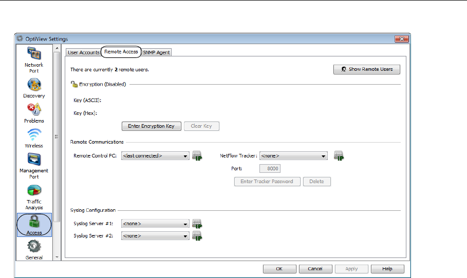
To Set Up Remote User Interface Encryption
1. Select the Link Status button.
2. Select the Access button.
40
OptiView XG Network Analysis Tablet
Getting Started Guide
3. Select the Remote Access tab.
4. Press the Enter Encryption Key button.
5. Select ASCII or Hexadecimal and enter the key. This key will be required when a remote user
attempts to initiate a remote session.
You can clear the encryption key by pressing the Clear Key button.
41
Security
Remote Connection Termination
To terminate a remote connection, close the OptiView Remote User Interface window on the
remote computer.
The remote connection will be terminated if the OptiView XG’s MAC or IP address is changed,
encryption is changed, cable test is executed, the OptiView XG is switched to receive-only mode,
or if the TCP/IP session is terminated for any reason.
Security
It is common practice to leave the OptiView XG powered-on and connected to a network. This lets
you become familiar with devices on the network and normal traffic patterns. However, it is
important to secure the OptiView XG from theft and unauthorized use.
You can physically secure the OptiView XG in place using a Kensington lock. You can lock the
OptiView XG by locking Windows. And you can create user accounts with specific privileges.
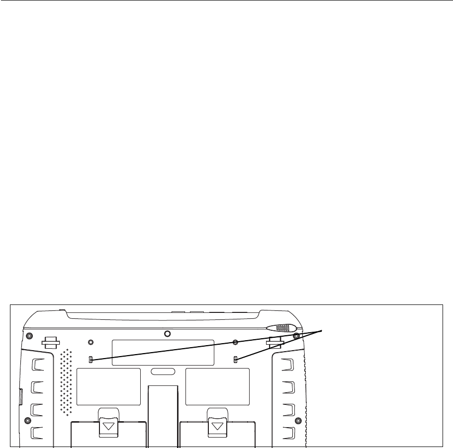
Physical Security: Kensington Lock
Kensington security slots are provided on the OptiView XG housing. You can reduce the chance of
theft by purchasing a Kensington lock and using it to secure the OptiView XG in place.
GLZ08.EPS
Figure 17. Kensington Security Slot
Kensington Security Slot
42
OptiView XG Network Analysis Tablet
Getting Started Guide
Controlling Access to the OptiView XG
Locking Windows 7
When the OptiView XG is connected to a network and running, and you want to leave it
unattended, you can restrict access by locking Windows 7. Press Ctrl+Alt+Del and choose Lock the
computer. However, this only provides protection if you have set up a user account in Windows 7.
Otherwise, the OptiView XG can be unlocked by pressing the Enter key.
OptiView XG User Accounts
To control access to certain features of the OptiView XG, set up a User Account for each user.
Permissions can be set for each user. The admin account must be enabled prior to setting up
additional user accounts.
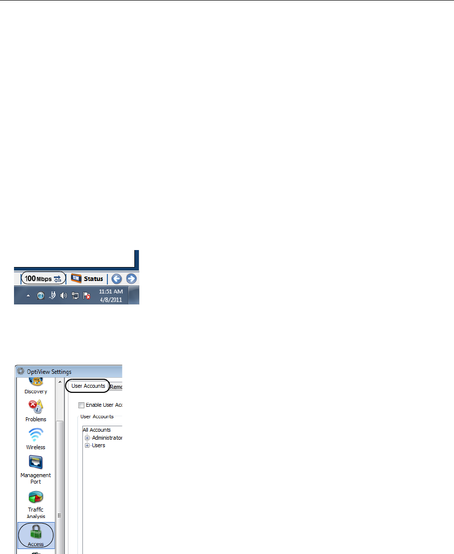
To Set Up User Accounts
1. Select the Link Status button to display the OptiView Settings screen.
2. Select the Access button.
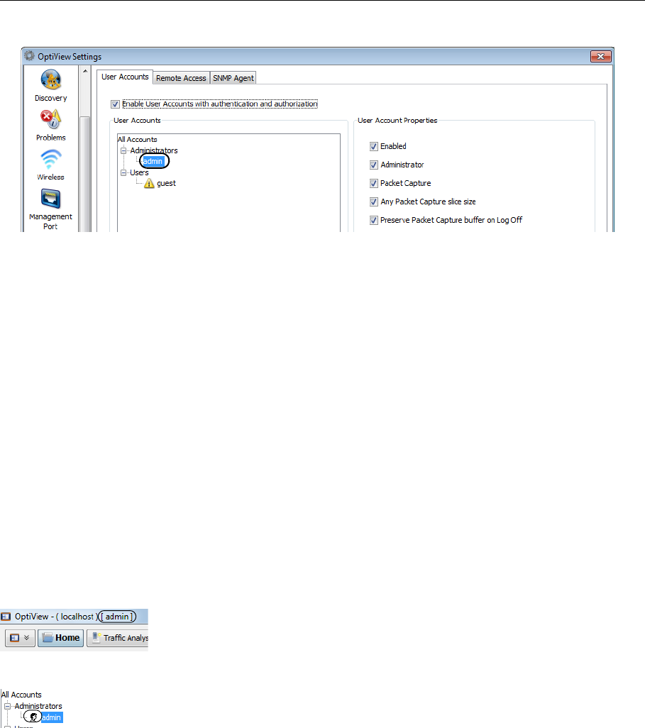
3. Select the User Accounts tab.
43
Security
4. Expand the Administrators tree and select the admin account.
5. Select the Create Password button and enter a password. The password field can be up to 40
characters in length. All characters (including spaces) are allowed for the password field.
6. Select the Enabled check box under User Account Properties.
Choose options under User Account Properties by checking the check boxes. Normally, all of the
boxes are selected for the administrator account. See the OptiView XG online help for
descriptions of the User Account check boxes.
7. Select the Apply button.
8. Be sure to select the Enable User Accounts with authentication and authorization check box!
When this box is not selected, all user accounts are disabled.
• You may now create additional user accounts if desired. Select the guest account if you’d like
to use it, or select the Add button to create new accounts. The Account name and password
fields can be up to 40 characters in length. All characters (including spaces) are allowed for
both the Account and password fields.
9. Select the OK button.
The user name (“admin” in this case) is displayed in the OptiView title bar.
An icon is displayed to the left of an account name to indicate that the user is logged-in.

44
OptiView XG Network Analysis Tablet
Getting Started Guide
To log off, close the OptiView application by selecting the “X” in the upper right corner or by
typing Alt+F4. You will need to log in (as admin or a user) whenever you re-start the OptiView XG
Network Analysis Tablet or the OptiView application.
• You can create up to 32 user accounts.
• For remote users, the encryption challenge occurs before the login challenge.
45
Removing and Replacing the Hard Drive
Removing and Replacing the Hard Drive
The hard drive can be removed from the OptiView XG for secure data management.
Caution
To prevent damage to the OptiView XG and/or the removable hard drive, use standard ESD
(electrostatic discharge) control procedures and equipment.
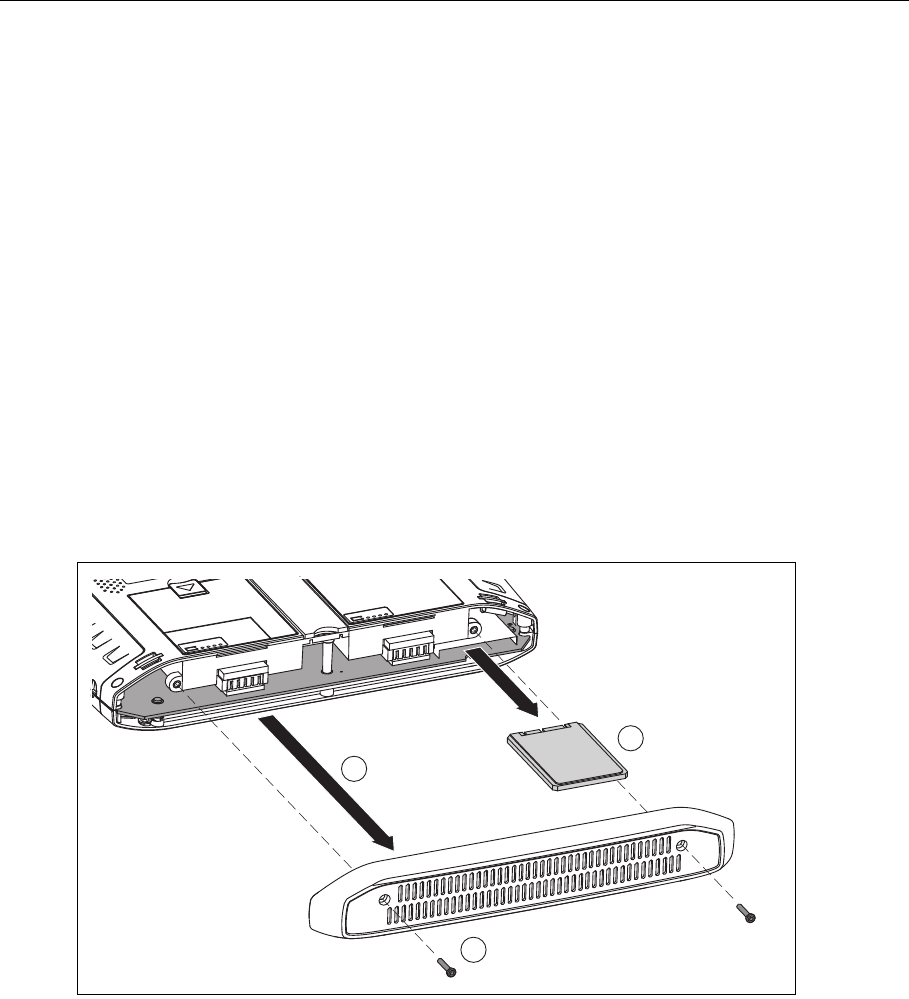
Removing the Hard Drive
The analyzer’s “Computer name” is stored on the hard drive. You can view the Computer name by
following the instructions in “Computer Name” on page 46. If desired, make note of the
analyzer’s Computer name so you can restore it after replacing the hard drive.
1. Power-off the OptiView XG by selecting Shut down in Windows 7.
2. Disconnect all cables from the OptiView XG.
3. Use a Phillips screwdriver to remove the two screws that secure the bottom panel.
4. Slide the hard drive out.
GLZ10.EPS
Figure 18. Replacing the Hard Drive
1
2
3

46
OptiView XG Network Analysis Tablet
Getting Started Guide
Replacing the Hard Drive
To replace the hard drive, reverse the preceding procedure.
The touchscreen calibration data is stored on the hard drive. You will need to re-calibrate the
touchscreen after replacing the hard drive. See “Multi-Touch Screen Calibration” on page 32.
Computer Name
The analyzer’s name is stored on the hard drive. You can change the analyzer’s name as follows.
1. Select the Windows 7 Start button.
2. Right-click (or touch and hold) Computer.
3. Select Properties.
4. Select Change settings in the Computer name, domain, and workgroup settings section.
Cleaning
Clean the OptiView XG housing, the touchscreen, and the batteries using a soft cloth that has
been moistened with mild detergent. Dry with a soft cloth. Do not spray liquid directly on the
OptiView XG or the batteries. Do not use harsh cleaners. Do not immerse.

47
Troubleshooting
Troubleshooting
If the OptiView XG is not operating as expected, refer to this table for possible causes and
solutions.
Table 8. Troubleshooting Guide
Problem Possible Cause & Solution
Cannot establish a network connection. The OptiView XG’s MAC addresses have not been added to the
network’s MAC access list.
The OptiView XG fails to get an IP address. There may be no connectivity to a DHCP server on the link. This
could be caused by a DHCP server that is not responding to
requests, in which case you would want to investigate the health
of the DHCP server.
If the analyzer is connected to a trunk port, ensure that the
selected VLAN has connectivity to an operational DHCP server, or
switch to a different VLAN.
Instructions for switching to a different VLAN:
1. Select the Link Status button. This opens the OptiView
Network Port Settings screen.
2. In the Active VLAN Configuration section, select a VLAN that
has connectivity to a DHCP server.
3. Select the OK button at the bottom of the screen.
Cannot establish a Wi-Fi connection. Enable Wi-Fi adapters. See page 20.
Cannot establish a network connection on
network ports A, B, C, or D.
Enable the Network Ports by switching on power to Network
Ports A, B, C, and D. See page 30.
The OptiView XG is not reporting all of the
expected networks, devices, and related
detail.
To ensure successful discovery both on-net and off-net, it is
critical that you configure Discovery. Select the OptiView button
(in the upper left corner of the display), then select the OptiView
Settings button. Select the Discovery button (at the left side of
the screen).
1. To ensure access to the information (SNMP-MIBs) on the
devices' SNMP agent, configure the SNMP credentials on the
SNMP Configuration tab.
2. Often the devices' SNMP agents are connected to a different
subnet than the one to which the OptiView is connected. These
SNMP or Management subnets need to be configured on the
Extended Discovery Ranges tab.
3. To allow the OptiView to discover networks beyond the subnet
to which it is connected, configure the remote subnets for
discovery using the Extended Discovery Ranges tab.

48
OptiView XG Network Analysis Tablet
Getting Started Guide
Windows Restore Options
In the event the Windows 7 operating system becomes unstable, there are two methods for
restoring stability.
• Windows System Restore restores the Windows configuration to an earlier point in time
without erasing your data files.
• Windows System Recovery erases all data files and returns the Windows system to its original
condition. Instructions are provided for backing up your data files before they are erased.
Windows System Restore
The Windows 7 operating system creates a restore point whenever you install new software. This
lets you restore the Windows configuration to an earlier point in time if desired. For example, if
you install a driver that when accessed, causes the system to hang, you can restore the Windows
operating system using Windows System Restore.
1. Select the Windows button, then select Control Panel.
2. In the search box, type System Restore.
3. Select Restore system files and settings from a restore point.
4. Follow the prompts.
Windows System Recovery
In the event the OptiView XG’s operating system becomes unstable, and you want to return the
OptiView XG to its factory default condition, you can restore the hard drive using the System
Recovery utility. This will effectively erase changes that were made since the OptiView XG left the
factory. It will leave the OptiView XG’s operating system and file system in a known, working
state.
Caution
Performing a System Recovery will
• Erase all report, capture, and other data files
• Erase all OptiView XG user accounts and passwords
• Remove all user-installed applications
• Return the OptiView XG to its factory default configuration
49
Windows Restore Options
The OptiView XG’s MAC address, purchased software options, and OptiView Power Control
settings will be preserved.
Caution
The OptiView XG could be rendered inoperable if the System Recovery process is interrupted.
The AC adapter (not batteries) should be used to power the OptiView XG during the recovery
process.
Procedure
Back Up Your Files
If you want to keep any files that currently exist on the OptiView XG’s hard drive, use Windows
Backup to save them to an external drive. You will need to deselect the “postgres” user account
from the backup.
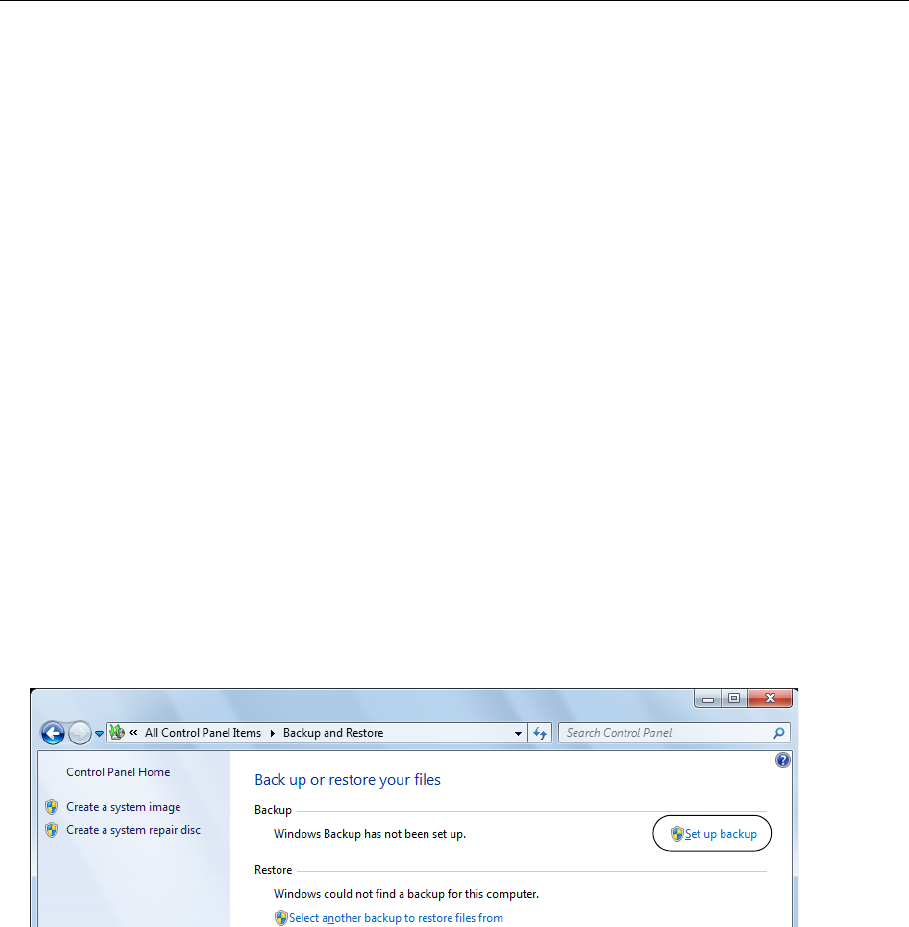
1. Select the Windows button, then select Control Panel.
2. Set the view control to View by: Small icons.
3. Select Backup and Restore.
Note that if you have previously set up a backup, the “Set up backup” button will not appear
on this screen. In that case you will need to choose Control Panel→Recovery→ Advanced
recovery methods→Reinstall Windows→Back up now and then proceed to step 5.
4. Select Set up backup.
50
OptiView XG Network Analysis Tablet
Getting Started Guide
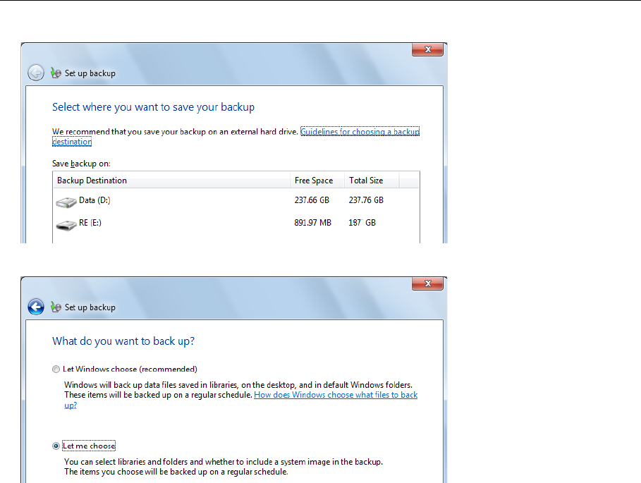
5. Choose an external destination drive for the backup.
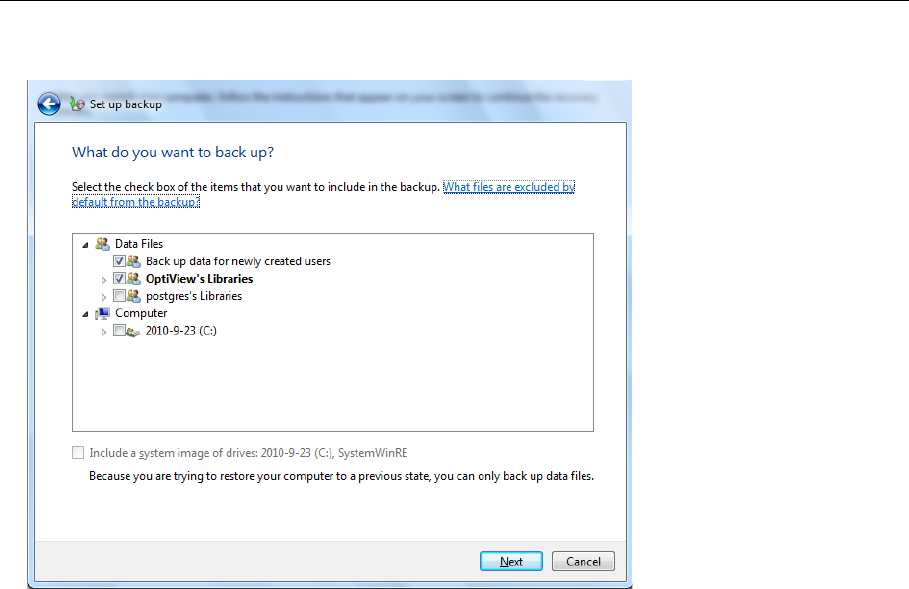
6. At the screen that says “What do you want to back up?” select Let me choose and select Next.
51
Windows Restore Options
7. At the “What do you want to back up?” screen deselect postgres’s Libraries and deselect
Include a system image....
8. At the “Review your backup settings” screen ensure that OptiView’s Libraries are included and
postgres’s Libraries are not included.
9. Select Save settings and run backup.
10. When the backup completes, disconnect the external drive from the OptiView XG.
Restore Windows System Files
1. Disconnect all cables from the OptiView XG except the AC adapter, the keyboard, and the
mouse.
2. Select the Windows 7 button and Restart the OptiView XG. When the Fluke Networks splash
screen appears, press the F8 key multiple times.
3. The Advanced Boot Options screen will appear. Verify that Repair Your Computer is selected,
then press Enter.
4. You can now use the mouse to make your selections. Follow the prompts to choose a
language.

52
OptiView XG Network Analysis Tablet
Getting Started Guide
5. At the User name and Password window, select the drop-down selector.
6. Select OptiView as the User name. You do not need to type anything in the Password box
unless you have created a password for this user.
7. Select OK.
8. At the Choose a recovery tool window, choose Reinstall Windows.
The recovery image will be written to the disk, and the old operating system’s directory will be
renamed C:\Windows.old. The C:\Windows.old directory consumes several gigabytes of storage
space on the disk. Verify that you have already saved any data files you need, then use the
Windows Disk Cleanup tool to delete all files (including hidden system files) in the C:\Windows.old
directory, as described below.
Post-Recovery File Clean-Up
1. Select the Windows Start Button, then type “free up disk space” in the search box.
2. Choose Free up disk space by deleting unnecessary files.
3. In the Drive Selection window, select the C: drive and wait for scanning to complete.
4. Select the Previous Windows installation(s) check box.
5. Select the Temporary Windows installation files check box.
6. Select or deselect other check boxes as desired.
7. Select OK.
8. Select Delete Files. The selected files will be deleted.
9. If you previously backed up data files to an external drive, connect the drive and use
Windows 7 Backup and Restore to restore your data files.

53
Specifications
Specifications
Physical Specifications
Environmental Specifications
1 Battery charging is disabled when internal temperature rises above 113°F (45°C).
2 Altitude specification applies to OptiView XG and batteries. Maximum altitude for adapter is
2000 m (6,600 ft.).
Dimensions (H,W,D) 9.45" x 12.43" x 2.03" (240 mm x 315.7 mm x 51.6 mm)
Weight 5.5 lb. (2.5 kg) with batteries; 4.5 lb. (1.8 kg) without batteries
Kensington Lock Kensington security slot on rear panel for connection of security cable
Operating Temperature132°F to 122°F (0°C to 50°C), up to 40% RH,
non-condensing
32°F to 86°F (0°C to 30°C), up to 95% RH,
non-condensing
Storage Temperature -40°F to +160°F (-40°C to +71°C)
Shock and Vibration Meets requirements of MIL-PRF-28800F for
Class 3 equipment
Safety EN 61010-1 2nd Edition
Altitude24600 m (15,000 ft.); Storage: 12000 m (39,000
ft.)
Pollution Degree 2 Normally only nonconductive pollution occurs.
Temporary conductivity caused by condensation
is to be expected.

54
OptiView XG Network Analysis Tablet
Getting Started Guide
Electrical Specifications
*Battery charging is disabled when internal temperature rises above 113°F (45°C).
AC Adapter Input 90-264 VAC, 47-63 Hz, 2.0 A max
AC Adapter Output 19 VDC, 4.74 A, 90 W
Caution: For safe operation, use only the supplied adapter.
Battery Two user-replaceable, rechargeable, 45 Watt-hour, lithium-ion
battery packs.
Battery Operating Time 2 hr. (typical)
Battery Charge Time* 3 hr. (typical). Charge time depends on residual battery charge and
analyzer power consumption while charging batteries.
Display Color LCD (1024 x 768 pixels) touchscreen
Network Analysis Ports Two 10/100/1000 Mbps RJ45 Ethernet ports
1000BASE-FX SFP socket
10000BASE-X SFP+ socket
Management Port 10/100/1000 Mbps RJ45 Ethernet connector
Supported SFP Modules 100BASE-FX - 1300 nm
1000BASE-SX - 850 nm
1000BASE-LX - 1310 nm
1000BASE-ZX - 1550 nm
Supported SFP+ Modules 10GBASE-LR - 1310 nm
10GBASE-LRM - 1310 nm
10GBASE-SR - 850 nm
Fault Tolerance RJ45 Ports are designed to withstand a maximum of 100 volts.
USB Ports Three USB 2.0 ports
eSATA Port eSATA port for connecting external hard drive
Video Port Standard VGA port for connection to monitor or projector

55
Specifications
Cables
Wireless Antennas
*External Antenna port is receive-only (no transmit).
Cable Types 100 Ω Unshielded Twisted Pair (UTP) LAN cables.
100 Ω Shielded or Screened Twisted Pair (SeTP) LAN cables.
TIA Category 3, 4, 5, 5e, and 6. ISO Class C, D and E).
Cable Length
Measurement
Measurable cable lengths are from 3 feet (0.9 meters) to 500 feet (152
meters).
Accuracy: ± 6 feet (± 2 meters).
Length measurement is based on Nominal Velocity of Propagation (NVP)
for selected cable type.
Internal Wireless Antennas Seven internal 2.4 GHz, 1.1 dBi peak, 5 GHz,
3.2 dBi peak antennas.
External Omni-directional Antenna* Antenna, WLAN, omnidirectional, 2.4 & 5 GHz,
802.11 A/B/G, 50 Ω. Gain: 2.1 dBi (2.45 GHz),
2.4 dBi (4.9 GHz), 2.6 dBi (5.25 GHz), 2.5 dBi
(5.875 GHz).
External Directional Antenna* Antenna, frequency range 2.4 - 2.5 and 4.9 -
5.9 GHz.
Minimum gain 5.0 dBi peak in the 2.4 GHz
band, and 7.0 dBi peak in the 5 GHz band.
External Antenna Connector* Reverse SMA

56
OptiView XG Network Analysis Tablet
Getting Started Guide
Wireless Adapters 1 & 2
Data Rate 802.11a: 6/9/12/24/36/48/54 Mbps
802.11b: 1/2/5.5/11 Mbps
802.11g: 6/9/12/24/36/48/54 Mbps
802.11n (20 MHz): MCS0-23, up to 216 Mbps
802.11n (40 MHz): MCS0-23, up to 450 Mbps
Operating
Frequency
2.412 ~ 2.484 GHz (Industrial Scientific Medical
Band)
5.170 ~ 5.825 GHz
Security 64/128-Bit WEP Key, WPA, WPA2, 802.1x
Transmit Output
Power*
(Tolerance:±1.5 dBm)
2.4 GHz 802.11b: 16.58 dBm at 2412 MHz
2.4 GHz 802.11g: 17.64 dBm at 2412 MHz
2.4 GHz 802.11 HT20: 27.17 dBm at 2412 MHz
2.4 GHz 802.11 HT40: 23.24 dBm at 2412 MHz
5725 MHz - 5850 MHz
802.11a: 22.69 dBm at 5825 MHz
802.11n HT20: 25.25 dBm at 5745 MHz
802.11n HT40: 23.83 dBm at 5795 MHz.
5150 MHz - 5250 MHz
802.11a: 13.41 dBm at 5220 MHz
802.11n HT20: 13.91 dBm at 5220 MHz
802.11n HT40: 14.06 dBm at 5230 MHz
5250 MHz - 5350 MHz
802.11a: 17.79 dBm at 5260 MHz
802.11n HT20: 18.91 dBm at 5300 MHz
802.11n HT40: 18.56 dBm at 5270 MHz
5470 MHz - 5725 MHz
802.11a: 16.72 dBm at 5500 MHz
802.11n HT20: 18.46 dBm at 5700 MHz
802.11n HT40: 16.49 dBm at 5670 MHz
Receive Sensitivity
(Tolerance: ±2 dBm)
802.11b: 8% PER
-90 dBm
802.11g: 10% PER
-80 dBm
802.11n: 2.4 GHz
10% PER
-72 dBm@HT20
-70 dBm@HT40
802.11a: 10% PER
-78 dBm
802.11n: 5 GHz 10%
PER
-70 dBm@HT20
-63 dBm@HT40

57
Specifications
*The maximum power setting will vary by channel and according to individual country regulations.
Supported Network Standards
Compliance Statements
Power Consumption
(Typical)
Transmitting (Legacy mode, HT20 mode):
870 mA @5 GHz, 700 mA @2.4 GHz.
Transmitting (HT40 mode):
900 mA @5 GHz, 750 mA @2.4 GHz.
Receiving (Legacy mode, HT20 mode):
550 mA @5 GHz, 520 mA @2.4 GHz.
Receiving (HT40 mode):
610 mA @5 GHz, 600 mA @2.4 GHz.
IEEE 10BASE-TX, IEEE 100BASE-TX,
IEEE 1000BASE-TX, IEEE 1000BASE-X
IEEE 10GBASE-X
RFCs: 1213, 1239, 1285, 1512, 1513, 1643,
2108, 2115, 2127, 2515, 2819, 3592, 3895,
3896, 4188, 4502.
EMC Complies with IEC/EN61326-1:2006, class A
Safety Complies with IEC/EN 61010-1:2001, CAN/CSA C22.2 No. 61010-1-04, ANSI/UL 61010-
1:2004, EN/IEC 60825-1:2007, EN/IEC 60825-2:2004+ A1:2007
Telephone The OptiView XG is NOT designed for connection to a telephone network.
The OptiView XG is NOT designed for connection to an ISDN line.
Do not connect to a telephone network or ISDN line except through a regulatory agency
compliant computer network modem device.

58
OptiView XG Network Analysis Tablet
Getting Started Guide
Federal Communication Commission and Industry Canada
Interference Statement
This equipment has been tested and found to comply with the limits for a Class A digital device,
pursuant to Part 15 of the FCC and IC Rules. These limits are designed to provide reasonable
protection against harmful interference in a residential installation. This equipment generates,
uses and can radiate radio frequency energy and, if not installed and used in accordance with the
instructions, may cause harmful interference to radio communications. However, there is no
guarantee that interference will not occur in a particular installation. If this equipment does cause
harmful interference to radio or television reception, which can be determined by turning the
equipment off and on, the user is encouraged to try to correct the interference by one of the
following measures:
• Reorient or relocate the receiving antenna.
• Increase the separation between the equipment and receiver.
• Connect the equipment into an outlet on a circuit different from that to which the receiver is
connected.
• Consult the dealer or an experienced radio or TV technician for help.
FCC Caution: Any changes or modifications not expressly approved by the party responsible for
compliance could void the user's authority to operate this equipment.
This device complies with Part 15 of the FCC standard(s). Operation is subject to the following two
conditions:
(1) this device may not cause interference, and
(2) this device must accept any interference, including interference that may cause undesired
operation of the device.
This device complies with Industry Canada licence-exempt RSS standard(s). Operation is subject to
the following two conditions:
(1) this device may not cause interference, and
(2) this device must accept any interference, including interference that may cause undesired
operation of the device.
Le présent appareil est conforme aux CNR d'Industrie Canada applicables aux appareils radio
exempts de licence. L'exploitation est autorisée aux deux conditions suivantes :
(1) l'appareil ne doit pas produire de brouillage, et
(2) l'utilisateur de l'appareil doit accepter tout brouillage radioélectrique subi, même si le
brouillage est susceptible d'en compromettre le fonctionnement.
Under Industry Canada regulations, this radio transmitter may only operate using an antenna of a
type and maximum (or lesser) gain approved for the transmitter by Industry Canada.

59
Specifications
To reduce potential radio interference to other users, the antenna type and its gain should be so
chosen that the equivalent isotropically radiated power (e.i.r.p.) is not more than that necessary
for successful communication.
Conformément à la réglementation d'Industrie Canada, le présent émetteur radio peut
fonctionner avec une antenne d'un type et d'un gain maximal (ou inférieur) approuvé pour
l'émetteur par Industrie Canada.
Dans le but de réduire les risques de brouillage radioélectrique à l'intention des autres
utilisateurs, il faut choisir le type d'antenne et son gain de sorte que la puissance isotrope
rayonnée équivalente (p.i.r.e.) ne dépasse pas l'intensité nécessaire à l'établissement d'une
communication satisfaisante.
OptiView XG Identification Numbers
FCC ID: WA7-OPTIVIEW-XG
IC ID: 6627C-OPTIVIEWXG

60
OptiView XG Network Analysis Tablet
Getting Started Guide
Exposure to RF Energy
THIS MODEL DEVICE MEETS U.S. AND INTERNATIONAL REQUIREMENTS FOR EXPOSURE TO RADIO
FREQUENCY RADIATION.
The OptiView XG is a radio transmitter and receiver. It is designed and manufactured not to
exceed the emission limits for exposure to radio frequency (RF) energy set by the Federal
Communications Commission of the U.S. Government and by the International Commission on
Non-Ionizing Radiation Protection (ICNIRP). The device also meets the European Radio and
Telecommunications Terminal Equipment (R&TTE) directive, for protecting the health and safety
of the user and other persons.
These limits are part of comprehensive guidelines that establish permitted levels of RF energy for
the general population. The guidelines are based on standards that were developed by
independent scientific organizations through periodic and thorough evaluation of scientific
studies. The standards include a substantial safety margin designed to assure the safety of all
persons, regardless of age and health.
Before a device model is available for sale to the public, it must be tested and certified to operate
within the limits for safe exposure established by the FCC and international organizations. The
tests are performed in positions and locations (e.g., next to the body) as required by the FCC for
each model. The FCC has granted an Equipment Authorization for this model device with all
reported SAR levels (see below) evaluated as in compliance with the FCC RF emission guidelines.
This device meets RF exposure guidelines when the antennas are positioned at a minimum
distance from the body. In order to transmit data or messages, this device requires a quality
connection to the network. In some cases, transmission of data or messages may be delayed until
such a connection becomes available. Be sure that the recommended distance is observed until
the transmission is complete.
The exposure standard for wireless devices employs a unit of measurement known as the Specific
Absorption Rate, or SAR. Tests for SAR are conducted using standard operating positions specified
by the FCC with the device transmitting at its highest certified power level in all tested frequency
bands. The SAR limit set by the FCC is 1.6 W/kg. The international guidelines state that the SAR
limit for mobile devices used by the public is 2.0 W/kg averaged over 10 grams of body tissue. SAR
values may vary depending on national reporting requirements and the network band. Although
the SAR is determined at the highest certified power level, the actual SAR level of the device while
operating can be well below the maximum value because the device operates at multiple power
levels and uses only the power required to reach the network.
SAR information on this model device is on file with the FCC and can be found under the Display
Grant section http://www.fcc.gov/oet/fccid after searching on FCC ID: WA7-OPTIVIEW-XG.

61
Specifications
Europe-EU Declaration of Conformity
This device complies with the essential requirements of the R&TTE Directive 1999/5/EC. The
following test methods have been applied in order to prove presumption of conformity with the
essential requirements of the R&TTE Directive 1999/5/EC:
• EN61010-1: 2001 A11: 2004
Safety requirements for electrical equipment for measurement, control, and laboratory use
• EN50385: (2002-08)
Product standard to demonstrate the compliance of radio base stations and fixed terminal
stations for wireless telecommunication systems with the basic restrictions or the reference
levels related to human exposure to radio frequency electromagnetic fields (110 MHz to
40 GHz) -General public
• EN 300 328 V1.7.1: (2006-10)
Electromagnetic compatibility and Radio spectrum Matters (ERM); Wideband Transmission
systems; Data transmission equipment operating in the 2.4 GHz ISM band and using spread
spectrum modulation techniques; Harmonized EN covering essential requirements under
article 3.2 of the R&TTE Directive
• EN 301 893 V1.4.1: (2007-07)
Broadband Radio Access Networks (BRAN);5 GHz high performance RLAN; Harmonized EN
covering essential requirements of article 3.2 of the R&TTE Directive
• EN 301 489-1 V1.6.1: (2005-09)
Electromagnetic compatibility and Radio Spectrum Matters (ERM); Electromagnetic
Compatibility (EMC) standard for radio equipment and services; Part 1: Common technical
requirements
• EN 301 489-17 V1.2.1 (2002-08)
Electromagnetic compatibility and Radio spectrum Matters (ERM); ElectroMagnetic
Compatibility (EMC) standard for radio equipment and services; Part 17: Specific conditions for
2.4 GHz wideband transmission systems and 5 GHz high performance RLAN equipment
This device is a 2.4 GHz wideband transmission system (transceiver), intended for use in all EU
member states and EFTA countries, except in France and Italy where restrictive use applies.
In Italy the end-user should apply for a license at the national spectrum authorities in order to
obtain authorization to use the device for setting up outdoor radio links and/or for supplying
public access to telecommunications and/or network services.
This device may not be used for setting up outdoor radio links in France and in some areas the RF
output power may be limited to 10 mW EIRP in the frequency range of 2454 MHz to 2483.5 MHz.
For detailed information the end-user should contact the national spectrum authority in France.
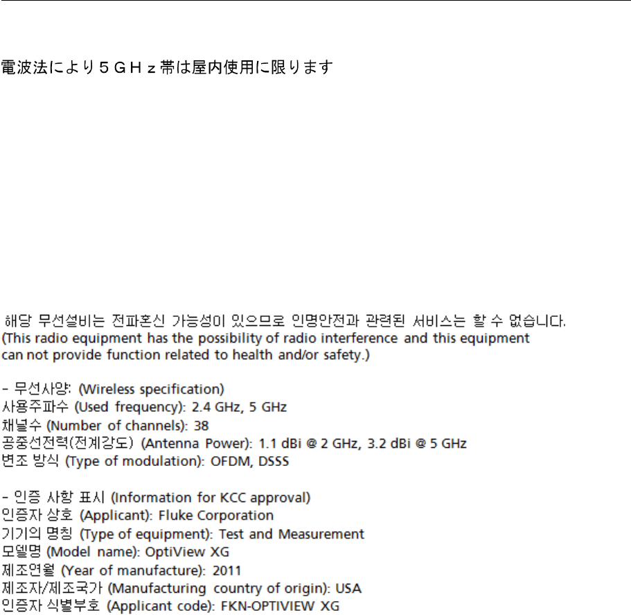
62
OptiView XG Network Analysis Tablet
Getting Started Guide
Japan
(5 GHz radio band method is limited to indoor use.)
Brazil
Este equipamento opera em caráter secundário, isto é, não tem direito a proteção contra
interferência prejudicial, mesmo de estações do mesmo tipo, e não pode causar interferência a
sistemas operando em caráter primário.
(This equipment operates on a secondary basis and, consequently, must accept harmful
interference, including from stations of the same kind, and may not cause harmful interference to
systems operating on a primary basis.)
Korea

63
Contacting Fluke Networks
Contacting Fluke Networks
Web: www.flukenetworks.com/contact
e-mail: support@flukenetworks.com
Phone:
• Australia: 61 (2) 8850-3333 or 61 (3) 9329 0244
• Beijing: 86 (10) 6512-3435
• Brazil: 11 3759 7600
• Canada: 1-800-363-5853
• Europe: +31-(0) 40 2675 600
• Hong Kong: 852 2721-3228
• Japan: 03-6714-3117
• Korea: 82 2 539-6311
• Singapore: +65-6799-5566
• Taiwan: (886) 2-227-83199
• USA: 1-800-283-5853

64
OptiView XG Network Analysis Tablet
Getting Started Guide