Nec Express5800 Gt110B Users Guide Express5800/GT110b
2015-05-18
: Nec Nec-Express5800-Gt110B-Users-Guide-728741 nec-express5800-gt110b-users-guide-728741 nec pdf
Open the PDF directly: View PDF ![]() .
.
Page Count: 494 [warning: Documents this large are best viewed by clicking the View PDF Link!]
- COVER
- SAFETY INDICATIONS
- PREFACE
- ABOUT THIS USER'S GUIDE
- IN THE PACKAGE
- CONTENTS
- 1. Notes on Using Your Server
- 2. General Description
- 3. Setting Up Your Server
- 4. Configuring Your Server
- 5. Installing the Operating System with Express Setup
- 6. Installing and Using Utilities
- 7. Maintenance
- 8. Troubleshooting
- SYSTEM VIEWERS
- LAMPS
- ERROR MESSAGES
- SOLVING PROBLEMS
- Problems with NEC Express Server
- Problems with Windows
- Problems with NEC EXPRESSBUILDER
- Problems with Express Setup
- Problems with Parameter File Creator
- Problems with RAID System Configuration
- Problems with Windows Autorun Menu
- Others
- Collecting Event Log
- Collect Configuration Information
- Collecting Dr. Watson Diagnostic Information
- Memory Dump
- RECOVERY FOR Windows SYSTEM
- MAINTENANCE TOOLS
- RESETTING THE SERVER
- FORCED SHUTDOWN
- 9. Upgrading Your Server
- 10. Internal Cabling Diagrams
- A. Specifications
- B. Other Precautions
- C. IRQ
- D. Installing Windows Server 2008 R2
- E. Installing Windows Server 2008
- F. Installing Windows Server 2003 x64 Editions
- G. Installing Windows Server 2003
- H. Using a Client Computer Which Has a CD Drive
- I. Product Configuration Record Table

N8100-1592F/1593F/1594F
NEC Express5800/GT110b
EXP260A
User's Guide
1st Edition
4-2010
ONL-510_015_01-GT110b-100-99-1003
PROPRIETARY NOTICE AND LIABILITY DISCLAIMER
The information disclosed in this document, including all designs and related materials, is the
valuable property of NEC Corporation (NEC) and /or its licensors. NEC and/or its licensors, as
appropriate, reserve all patent, copyright and other proprietary rights to this document, including all
design, manufacturing, reproduction, use, and sales rights thereto, except to the extent said rights are
expressly granted to others.
The NEC product(s) discussed in this document are warranted in accordance with the terms of the
Warranty Statement accompanying each product. However, actual performance of each such
product is dependent upon factors such as system configuration, customer data, and operator control.
Since implementation by customers of each product may vary, the suitability of specific product
configurations and applications must be determined by the customer and is not warranted by NEC.
To allow for design and specification improvements, the information in this document is subject to
change at any time, without notice. Reproduction of this document or portions thereof without prior
written approval of NEC is prohibited.
First Printing, April 2010
Copyright 2010
NEC Corporation
7-1 Shiba 5-Chome, Minato-Ku
Tokyo 108-8001, Japan
All Rights Reserved
Printed in Japan
Keep this manual at hand for quick reference at anytime necessary.
SAFETY INDICATIONS
Follow the instructions in this manual for your safety to use the NEC Express server.
Your server contains components with possible danger, hazards that may cause by ignoring
warnings, and preventive actions against such hazards.
Server components with possible danger are indicated with a warning label placed on or around
them as well as described in this manual.
In this manual or warning labels, "WARNING" or "CAUTION" is used to indicate a degree of danger.
These terms are defined as follows:
WARNING Indicates the presence of a hazard that may result in death or serious
personal injury if the instruction is ignored.
CAUTION Indicates the presence of a hazard that may cause minor personal injury,
including burns, or property damage if the instruction is ignored.
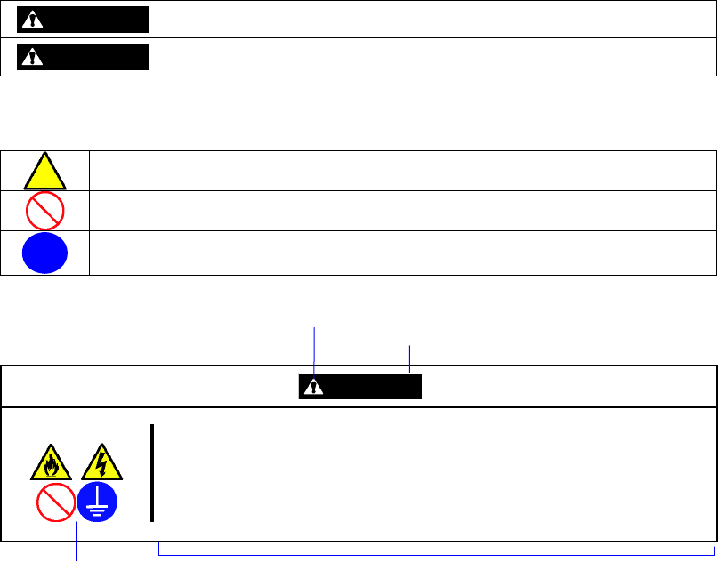
Precautions and notices against hazards are presented with one of the following three symbols. The
individual symbols are defined as follows:
This symbol indicates the presence of a hazard if the instruction is ignored.
An image in the symbol illustrates the hazard type. (Attention)
This symbol indicates prohibited actions. An image in the symbol illustrates a
particular prohibited action. (Prohibited Action)
This symbol indicates mandatory actions. An image in the symbol illustrates a
mandatory action to avoid a particular hazard. (Mandatory Action)
(Example)
Symbol to draw attention
Term indicating a degree of danger
CAUTION
Plug in to a proper power source.
Use a proper wall outlet of the specified voltage. Use of an improper power
source may cause a fire or a power leak.
Symbol indicating a prohibited
action (may not always be
indicated)
Description of a danger
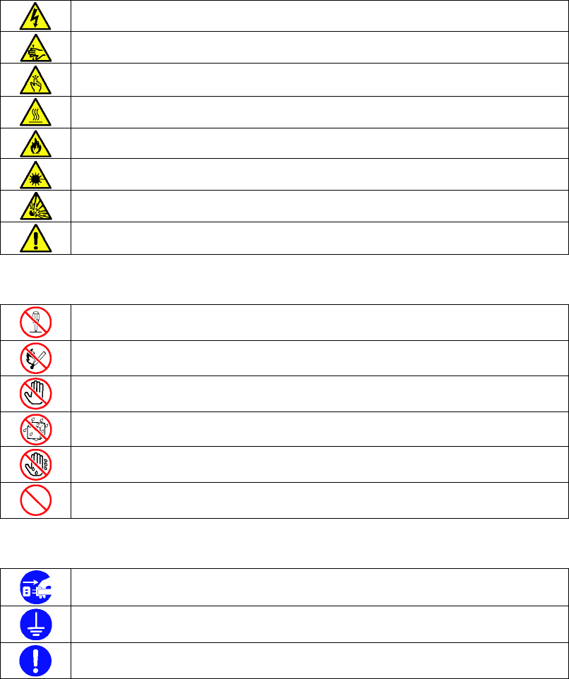
SYMBOLS USED IN THIS MANUAL AND WARNING LABELS
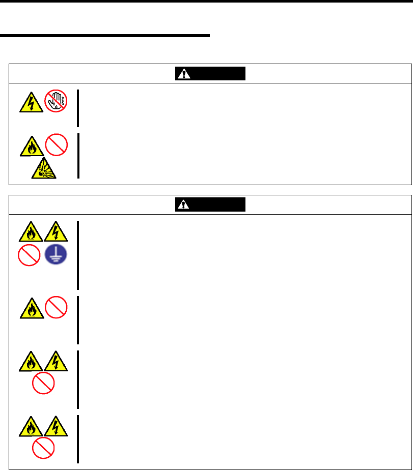
Attentions
Indicates that improper use may cause an electric shock.
Indicates that improper use may cause fingers to be caught.
Indicates that improper use may cause personal injury.
Indicates that improper use may cause personal injury.
Indicates that improper use may cause fumes or fire.
Indicates that improper use may cause loss of eyesight due to laser beam.
Indicates that improper use may cause explosion.
Indicates a general notice or warning that cannot be specifically identified.
Prohibited Actions
Do not disassemble, repair, or modify the server. Otherwise, an electric shock or fire
may be caused.
Do not place the server near the fire. Otherwise, a fire may be caused.
Do not touch the component specified by this symbol. Otherwise, an electric shock or
burn may be caused.
Do not use the server in the place where water or liquid may pour. Otherwise, an
electric shock or fire may be caused.
Do not touch the server with wet hand. Otherwise, an electric shock may be caused.
Indicates a general prohibited action that cannot be specifically identified.
Mandatory Action
Unplug the power cord of the server. Otherwise, an electric shock or fire may be
caused.
Be sure to provide earthing. Otherwise, an electric shock or fire may be caused.
Indicates a mandatory action that cannot be specifically identified. Make sure to follow
the instruction.

NOTE: This equipment has been tested and found to comply with the limits for a Class A digital
device, pursuant to Part 15 of the FCC Rules. These limits are designed to provide reasonable
protection against harmful interference when the equipment is operated in a commercial
environment. This equipment generates, uses, and can radiate radio frequency energy and, if not
installed and used in accordance with the instruction manual, may cause harmful interference to
radio communications. Operation of this equipment in a residential area is likely to cause harmful
interference in which case the user will be required to correct the interference at his own expense.
CE Statement
Warning: This is a Class A product. In domestic environment this product may cause radio
interference in which case the user may be required to take adequate measures (EN55022).
BSMI Statement
Trademarks
NEC ESMPRO and NEC EXPRESSBUILDER are trademarks of NEC Corporation.
Microsoft, Windows, Windows Server, and MS-DOS are registered trademarks or trademarks of Microsoft Corporation in the
United States and other countries.
Intel, Pentium, Xeon, and Celeron are registered trademarks of Intel Corporation.
PCI Express is a trademark of Peripheral Component Interconnect Special Interest Group.
Datalight is a registered trademark of Datalight, Inc.
ROM-DOS is a registered trademark of Datalight, Inc.
AT is a registered trademark of International Business Machines Corporation in the United States and other countries.
Adaptec and its logo is a registered trademark of Adaptec, Inc. of United States.
LSI, the LSI logo design, iBBU, MegaRAID, and WebBIOS are trademarks or registered trademarks of LSI Corporation of
United States.
Adobe, Adobe logo, and Acrobat are trademarks of Adobe Systems Incorporated.
Advanced Intelligent Tape is a trademark of the Sony Corporation.
Promise Technology, Inc. and Promise Technology, Inc. logo are trademarks of Promise Technology Incorporated.
AVOCENT and DVC (Dambrackas Video Compression) are registered trademarks or trademarks of AVOCENT in the United
States and other countries.
All other product, brand, or trade names used in this publication are the trademarks or registered trademarks of their
respective trademark owners.
Windows Server 2008 R2 stands for Microsoft® Windows Server® 2008 R2 Standard operating system and Microsoft®
Windows Server® 2008 R2 Enterprise operating system. Windows 7 stands for Microsoft® Windows® 7 Professional
operating system. Windows Server 2008 stands for Microsoft® Windows Server® 2008 Standard operating system and
Microsoft® Windows Server® 2008 Enterprise operating system. Windows Vista stands for Microsoft® Windows Vista®
Business operating system. Windows Server 2003 x64 Editions stands for Microsoft® Windows Server® 2003 R2, Standard
x64 Edition Operating system and Microsoft® Windows Server® 2003 R2, Enterprise x64 Edition operating system, or
Microsoft® Windows Server® 2003, Standard x64 Edition operating system and Microsoft® Windows Server® 2003,
Enterprise x64 Edition operating system. Windows Server 2003 stands for Microsoft® Windows Server® 2003 R2, Standard
Edition operating system and Microsoft® Windows Server® 2003 R2, Enterprise Edition operating system, or Microsoft®
Windows Server® 2003, Standard Edition operating system and Microsoft® Windows Server® 2003, Enterprise Edition
operating system. Windows XP x64 Edition stands for Microsoft® Windows® XP Professional x64 Edition operating system.
Windows XP stands for Microsoft® Windows® XP Home Edition operating system and Microsoft® Windows® XP
Professional operating system. Windows 2000 stands for Microsoft® Windows® 2000 Server operating system and
Microsoft® Windows® 2000 Advanced Server operating system, and Microsoft® Windows® 2000 Professional operating
system. Windows NT stands for Microsoft® Windows NT® Server network operating system version 3.51/4.0 and
Microsoft® Windows NT® Workstation operating system version 3.51/4.0. Windows Me stands for Microsoft® Windows®
Millennium Edition operating system. Windows 98 stands for Microsoft® Windows®98 operating system. Windows 95
stands for Microsoft® Windows®95 operating system. WinPE stands for Microsoft® Windows® Preinstallation
Environment.
Momentary voltage drop prevention:
This product may be affected by a momentary voltage drop caused by lightning. To prevent a momentary
voltage drop, an AC uninterruptible power supply (UPS) unit should be used.
Notes:
(1) No part of this manual may be reproduced in any form without the prior written permission of NEC
Corporation.
(2) The contents of this manual may be revised without prior notice.
(3) The contents of this manual shall not be copied or altered without the prior written permission of NEC
Corporation.
(4) All efforts have been made to ensure the accuracy of all information in this manual. If you notice any part
unclear, incorrect, or omitted in this manual, contact the sales agent where you purchased this product.
(5) NEC assumes no liability arising from the use of this product, nor any liability for incidental or
consequential damages arising from the use of this manual regardless of Item (4).

i
PREFACE
Congratulations on the purchase of your NEC Express server.
Purchase of this server is your assurance of receiving state-of-the-art, high quality hardware to meet
your needs, both now and in the future.
Read this User's Guide thoroughly to fully understand handling of the NEC Express server and
appreciate its functions to the maximum extent.

ii
ABOUT THIS USER'S GUIDE
This manual is a guide for proper setup and use of your server.
This manual also covers useful procedures for dealing with difficulties and problems that may arise
during setup or operation of your server.
Keep this manual for future use.
The following describes how to proceed with this manual.
How to Use This Manual
To aid you in finding information quickly, this manual contains the following information:
Chapter 1 Notes on Using Your Server
includes information that needs attention to use the server. Make sure to read this chapter
before setting up and using the server. It also includes requirements and advisory information
for transfer and disposal of the server.
Chapter 2 General Description
includes information necessary to use the server, such as names and functions of its
components, handling of the optical disk drive.
Chapter 3 Setting Up Your Server
tells you how to select a site, unpack the system, make cable connections, and power on your
system.
Chapter 4 Configuring Your Server
tells you how to configure the system and provides instructions for running the BIOS SETUP
Utility and the RAID configuration utility, which is used to configure RAID drives in your system.
This chapter also provides information on mother board jumper settings.
Chapter 5 Installing the Operating System with Express Setup
describes how to install the operating system.
Chapter 6 Installing and Using Utilities
describes how to install the utilities for the server. It also includes a description on using the
attached "NEC EXPRESSBUILDER" DVD.
Chapter 7 Maintenance
provides you with all the information necessary to maintain successful operation of the server.
This chapter also includes a description on relocating and storing the server.
Chapter 8 Troubleshooting
contains helpful information for solving problems that might occur with your system.
Chapter 9 Upgrading Your Server
provides you with instructions for upgrading your system with an additional processor, optional
memory, optional add-in cards, hard disk drives, peripheral devices, and power supply.
Chapter 10 Internal Cabling Diagram
includes cabling information for the SATA2 controller, 5.25-inch device, and the power supply.
Appendix A Specification
provides specifications for your server.
Appendix B Other Precautions
provides supplementary notes on using the server.
Appendix C IRQ
provides a list of factory-set IRQs.

iii
Appendix D Installing Windows Server 2008 R2
describes how to install Microsoft Windows Server 2008 R2 without using Express Setup. Using
the Express Setup tool is recommended for installing Windows Server 2008 R2. See Chapter 5
for details.
Appendix E Installing Windows Server 2008
describes how to install Microsoft Windows Server 2008 without using Express Setup. Using the
Express Setup tool is recommended for installing Windows Server 2008. See Chapter 5 for
details.
Appendix F Installing Windows Server 2003 x64 Editions
describes how to install Microsoft Windows Server 2003 x64 Editions without using Express
Setup. Using the Express Setup tool is recommended for installing Windows Server 2003 x64
Editions. See Chapter 5 for details.
Appendix G Installing Windows Server 2003
describes how to install Microsoft Windows Server 2003 without using Express Setup. Using the
Express Setup tool is recommended for installing Windows Server 2003. See Chapter 5 for
details.
Appendix H Using a Client Computer Which Has a CD Drive
describes how to install the management software of EXPRESSBUILDER to the client computer
without the DVD drive.
Appendix I Product Configuration Record Table
provides a table to be filled with your server configuration.
Text Conventions
The following conventions are used throughout this manual. For safety symbols, see "SAFETY
INDICATIONS" provided earlier.
IMPORTANT: Items that are mandatory or require attention when using the server
NOTE: Helpful and convenient piece of information
IN THE PACKAGE
The carton contains various accessories, as well as the server itself. See the “Getting Started” to
make sure that you have everything and that individual components are not damaged. If you find
any component missing or damaged, contact your service representative.
Store the provided accessories in a designated place for your convenience. You will need
them to install an optional device or troubleshoot your server, as well as to set it up.
Make a backup copy of each provided floppy disk, if any. Store the original disk as the
master disk in a designated place, and use its copy.
Improper use of any provided floppy disk or CD-ROM may alter your system
environment. If you find anything unclear, immediately ask your service representative for
help.

iv
CONTENTS
Preface ..............................................................................................................................................i
About This User's Guide..................................................................................................................ii
In the Package.................................................................................................................................iii
Chapter 1 Notes on Using Your Server........................................................................ 1-1
Warning Labels.............................................................................................................................1-2
Safety Notes..................................................................................................................................1-3
General .....................................................................................................................................1-3
Power Supply and Power Cord Use .........................................................................................1-4
Installation, Relocation, Storage, and Connection....................................................................1-6
Cleaning and Working with Internal Devices...........................................................................1-7
During Operation .....................................................................................................................1-8
For Proper Operation ....................................................................................................................1-9
Transfer to Third Party................................................................................................................1-10
Disposal and Consumables .........................................................................................................1-11
Regarding the Transportation of this System..............................................................................1-11
User Support...............................................................................................................................1-11
USE of the term “Optical Disk drive” ........................................................................................1-11
USE of the term “hard disk drive”..............................................................................................1-12
Chapter 2 General Description ..................................................................................... 2-1
Overview ......................................................................................................................................2-2
System Chassis .............................................................................................................................2-3
Front View................................................................................................................................2-3
Rear View.................................................................................................................................2-5
Internal View ............................................................................................................................2-7
Mother Board .........................................................................................................................2-10
Standard Features........................................................................................................................2-11
Remote Power-On Feature (Wake On LAN)..........................................................................2-12
AC LINK Feature...................................................................................................................2-12
Security ..................................................................................................................................2-12
Running the Server with the Fan Set to Low-speed Mode (Silent Mode)..............................2-13
NEC EXPRESSBUILDER.....................................................................................................2-13
NEC ESMPRO.......................................................................................................................2-14
Maintenance Tools .................................................................................................................2-14
System Diagnostic Utility ......................................................................................................2-14
Using Your Server.......................................................................................................................2-15
POWER/SLEEP Switch .........................................................................................................2-15
Power Off ...............................................................................................................................2-19
SLEEP Switch ........................................................................................................................2-19
Optical Disk Drive .................................................................................................................2-20
Flash FDD ..............................................................................................................................2-23
Chapter 3 Setting Up Your Server ................................................................................ 3-1
Setup Flow....................................................................................................................................3-2
UNPACKING THE SYSTEM......................................................................................................3-3
Installing Optional Devices ..........................................................................................................3-3

v
Selecting Server Site.....................................................................................................................3-4
Connecting Peripheral Devices.....................................................................................................3-6
Connecting Power Cord................................................................................................................3-8
Turning On the Server ................................................................................................................3-10
Installing Operating System .......................................................................................................3-12
Installing Utilities .......................................................................................................................3-12
Making Backup Copies of System Information..........................................................................3-12
Chapter 4 Configuring Your Server.............................................................................. 4-1
System BIOS (BIOS Setup Utility) ..............................................................................................4-2
Starting SETUP Utility.............................................................................................................4-3
Description on On-Screen Items and Key Usage .....................................................................4-4
Configuration Examples...........................................................................................................4-5
Menu and Parameter Descriptions ...........................................................................................4-9
RAID System Configuration ......................................................................................................4-23
RAID......................................................................................................................................4-23
Configuration by Onboard RAID Controller..........................................................................4-28
Setup Utility ...........................................................................................................................4-30
LSI Software RAID Configuration Utility and Universal RAID Utility................................4-43
Configuring Mother Board Jumpers ...........................................................................................4-46
Chapter 5 Installing the Operating System with Express Setup............................... 5-1
About Express Setup ....................................................................................................................5-2
Windows Server 2008 R2 .............................................................................................................5-3
Notes on Windows Installation.................................................................................................5-3
Flow of Setup ...........................................................................................................................5-8
Installing the Windows Server 2008 R2...................................................................................5-9
Installing and Setting Device Drivers.....................................................................................5-22
Setting for Solving Problems .................................................................................................5-27
BitLocker................................................................................................................................5-27
Windows Server 2008.................................................................................................................5-28
Notes on Windows Installation...............................................................................................5-28
Flow of Setup .........................................................................................................................5-33
Installing the Windows Server 2008.......................................................................................5-34
Installing and Setting Device Drivers.....................................................................................5-48
Setting for Solving Problems .................................................................................................5-54
Windows Server 2003.................................................................................................................5-55
Notes on Windows Installation...............................................................................................5-55
Flow of Setup..............................................................................................................................5-60
Installing Windows Server 2003.................................................................................................5-61
Installing and Setting Device Drivers.........................................................................................5-71
PROSet...................................................................................................................................5-71
Network Driver ......................................................................................................................5-73
Optional Network Board Driver.............................................................................................5-74
Setup Team.............................................................................................................................5-75
Setting WOL ..........................................................................................................................5-77
Graphics Accelerator Driver...................................................................................................5-79
Installing SCSI Controller Driver (N8103-75/95/107)...........................................................5-79
Installing SAS Controller Driver (N8103-104A) ...................................................................5-79
Setting for Solving Problems .................................................................................................5-79

vi
Setting for Solving Problems......................................................................................................5-80
Memory Dump (Debug Information).....................................................................................5-80
How to Create a User-mode Process Dump File....................................................................5-87
Network Monitor....................................................................................................................5-90
Re-installing the Operation System if Multiple Logical Drives Exist....................................5-92
Installing Maintenance Utilities..................................................................................................5-94
Updating the System...................................................................................................................5-94
Making Backup Copies of System Information..........................................................................5-95
Installing with the OEM-Disk for Mass Storage Device........................................................5-96
Chapter 6 Installing and Using Utilities ....................................................................... 6-1
NEC EXPRESSBUILDER...........................................................................................................6-2
Autorun Menu ..........................................................................................................................6-6
Parameter File Creator..................................................................................................................6-7
Parameter File ..........................................................................................................................6-8
NEC ESMPRO ...........................................................................................................................6-21
Functions and Features...........................................................................................................6-21
NEC ExpressUpdate Agent.........................................................................................................6-22
Universal RAID Utility...............................................................................................................6-23
Setup with Express Setup .......................................................................................................6-23
Manual Setup .........................................................................................................................6-23
Management of RAID System using NEC ESMPRO Manager.............................................6-24
Easy Configuration.................................................................................................................6-24
Creating Logical Drive of RAID 6.........................................................................................6-24
NEC Product Info Collection Utility ..........................................................................................6-25
Installation..............................................................................................................................6-25
Using Utility...........................................................................................................................6-26
Uninstallation .........................................................................................................................6-26
Chapter 7 Maintenance.................................................................................................. 7-1
Making Backup Copies.................................................................................................................7-1
Cleaning........................................................................................................................................7-2
Cleaning the Server ..................................................................................................................7-3
Cleaning the Keyboard/Mouse.................................................................................................7-3
Cleaning Disc ...........................................................................................................................7-4
System Diagnostics.......................................................................................................................7-5
Test Items.................................................................................................................................7-5
Startup and Exit of System Diagnostics ...................................................................................7-6
Relocating/Storing The Server......................................................................................................7-9
Chapter 8 Troubleshooting ........................................................................................... 8-1
System Viewers ............................................................................................................................8-2
Lamps ...........................................................................................................................................8-3
POWER/SLEEP Lamp.............................................................................................................8-4
DISK ACCESS Lamp ..............................................................................................................8-4
Access Lamp ............................................................................................................................8-4
LINK/ACT Lamp.....................................................................................................................8-4
1000/100/10 Lamp ...................................................................................................................8-4
Error Messages .............................................................................................................................8-5
Error Messages after Power-on ................................................................................................8-5

vii
POST Error Messages ..............................................................................................................8-6
Beep Codes...............................................................................................................................8-8
DMI Event Log ........................................................................................................................8-9
Solving Problems........................................................................................................................8-11
Problems with NEC Express Server.......................................................................................8-11
Problems with Windows.........................................................................................................8-17
Problems with NEC EXPRESSBUILDER ............................................................................8-27
Problems with Express Setup .................................................................................................8-28
Problems with Parameter File Creator ...................................................................................8-29
Problems with RAID System Configuration..........................................................................8-30
Problems with Windows Autorun Menu ................................................................................8-32
Others .....................................................................................................................................8-33
Collecting Event Log .............................................................................................................8-34
Collect Configuration Information.........................................................................................8-34
Collecting Dr. Watson Diagnostic Information ......................................................................8-35
Memory Dump.......................................................................................................................8-35
Recovery for Windows System...................................................................................................8-36
Maintenance Tools......................................................................................................................8-37
Starting Maintenance Tools....................................................................................................8-37
Function of Maintenance Tools ..............................................................................................8-40
Resetting the Server....................................................................................................................8-42
Forced Shutdown........................................................................................................................8-43
Chapter 9 Upgrading Your Server ................................................................................ 9-1
Safety Notes..................................................................................................................................9-2
Static Precautions..........................................................................................................................9-3
Preparing for Installation and Removal ........................................................................................9-4
Installation or Removal Procedure ...............................................................................................9-5
Side Cover................................................................................................................................9-5
Front Bezel...............................................................................................................................9-9
3.5-inch Hard Disk Drive .......................................................................................................9-11
2.5-inch Hard Disk Drive Cage (Option) ...............................................................................9-18
Use of Internal Hard Disk Drives in the RAID System..........................................................9-23
Additional Battery for Optional RAID Controller .................................................................9-28
PCI Board...............................................................................................................................9-36
Installation of N8117-01A RS-232C Connector Kit...............................................................9-43
DIMM ....................................................................................................................................9-45
File Device .............................................................................................................................9-50
Optical Disk Drive .................................................................................................................9-56
Chapter 10 Internal Cabling Diagrams....................................................................... 10-1
Interface Cables ..........................................................................................................................10-2
Addition of Hard Disk Drive..................................................................................................10-2
Connection of 5.25-inch Device.............................................................................................10-6
Power Cables ..............................................................................................................................10-9
Onboard SATA HDD..............................................................................................................10-9
With Optional RAID Controller Installed ............................................................................10-10
Appendix A Specifications............................................................................................A-1

viii
Appendix B Other Precautions.....................................................................................B-1
Transfer Rate of the On-board LAN Controller ...................................................................... B-1
Server Management Software ................................................................................................. B-1
Floppy Disk............................................................................................................................. B-1
DVD/CD-ROM ....................................................................................................................... B-4
Tape Media.............................................................................................................................. B-4
Keyboard ................................................................................................................................. B-5
Mouse...................................................................................................................................... B-6
Appendix C IRQ..............................................................................................................C-1
Appendix D Installing Windows Server 2008 R2 ........................................................D-1
Notice ..........................................................................................................................................D-1
Optional Board Supported by NEC EXPRESSBUILDER......................................................D-1
Service Pack Which EXPRESSBUILDER Supports ..............................................................D-2
Installing Service Pack............................................................................................................D-2
Updating System .....................................................................................................................D-2
Installing on the Mirrored Volume ..........................................................................................D-2
Mounting MO Device .............................................................................................................D-2
About Removable Media ........................................................................................................D-2
Floppy Disk Drive...................................................................................................................D-2
About the System Partition Size..............................................................................................D-3
BitLocker.................................................................................................................................D-4
Installing Windows Server 2008 R2 ............................................................................................D-6
Preparations for Installation ....................................................................................................D-6
Creating "Windows Server 2008 R2 OEM-Disk for EXPRESSBUILDER" ..........................D-6
Windows Server 2008 R2 Clean Installation...........................................................................D-9
Procedure for License Authentication ...................................................................................D-18
Updating the System .............................................................................................................D-18
Driver Installation and Advanced Settings ................................................................................D-21
LAN Driver and PROSet.......................................................................................................D-21
Network Driver .....................................................................................................................D-22
Optional Network Board Driver (N8104-121/125A/126) .....................................................D-22
Setup Team............................................................................................................................D-23
Setting WOL .........................................................................................................................D-26
Graphics Accelerator Driver..................................................................................................D-27
Installing SCSI Controller Driver (N8103-75/107)...............................................................D-27
Installing SAS Controller Driver (N8103-104A) ..................................................................D-27
About Windows Activation ...................................................................................................D-28
Setting for Solving Problems.....................................................................................................D-32
Appendix E Installing Windows Server 2008 ..............................................................E-1
Notice .......................................................................................................................................... E-1
Optional Board Supported by NEC EXPRESSBUILDER...................................................... E-1
Service Pack Which EXPRESSBUILDER Supports .............................................................. E-2
Installing Service Pack............................................................................................................ E-2
Updating System ..................................................................................................................... E-2
Installing on the Mirrored Volume .......................................................................................... E-2
Mounting MO Device ............................................................................................................. E-2

ix
About Removable Media ........................................................................................................ E-2
Floppy Disk Drive................................................................................................................... E-2
About the System Partition Size.............................................................................................. E-3
BitLocker................................................................................................................................. E-5
Installing Windows Server 2008..................................................................................................E-6
Preparations for Installation .................................................................................................... E-6
Creating "Windows Server 2008 OEM-Disk for EXPRESSBUILDER"................................ E-6
Windows Server 2008 Clean Installation ................................................................................ E-9
Procedure for License Authentication ................................................................................... E-20
Updating the System .............................................................................................................E-20
Driver Installation and Advanced Settings ................................................................................ E-23
LAN Driver and PROSet....................................................................................................... E-23
Network Driver ..................................................................................................................... E-25
Optional Network Board Driver (N8104-112/119/120/121/125A/126) ................................ E-25
Setup Team............................................................................................................................ E-26
Setting WOL ......................................................................................................................... E-28
Graphics Accelerator Driver.................................................................................................. E-29
Installing SCSI Controller Driver (N8103-75/95/107).......................................................... E-29
Installing SAS Controller Driver (N8103-104A) .................................................................. E-29
About Windows Activation ................................................................................................... E-30
Setting for Solving Problems..................................................................................................... E-34
Appendix F Installing Windows Server 2003 x64 Editions ........................................ F-1
Notice .......................................................................................................................................... F-1
Optional Board Supported by NEC EXPRESSBUILDER...................................................... F-1
Service Pack Which EXPRESSBUILDER Supports .............................................................. F-2
Installing Service Pack............................................................................................................ F-2
Updating System ..................................................................................................................... F-2
Re-installing to the Hard Disk Drive which has been upgraded to Dynamic Disk ................. F-2
Mounting MO Device ............................................................................................................. F-2
About Removable Media ........................................................................................................ F-2
Floppy Disk Drive................................................................................................................... F-2
About the System Partition Size.............................................................................................. F-3
Installing Windows Server 2003 x64 Editions............................................................................. F-4
Creating "Windows Server 2003 x64 Edition OEM-Disk for EXPRESSBUILDER" ......... F-4
Windows Server 2003 x64 Editions Clean Installation ........................................................... F-7
Procedure for License Authentication ....................................................................................F-11
Updating the System - Applying Service Pack - ................................................................... F-12
Driver Installation and Advanced Settings ................................................................................ F-19
PROSet.................................................................................................................................. F-19
Network Driver ..................................................................................................................... F-21
Optional Network Board Driver............................................................................................ F-22
Setup Team............................................................................................................................ F-23
Setting WOL ......................................................................................................................... F-25
Graphics Accelerator Driver.................................................................................................. F-27
Installing SCSI Controller Driver (N8103-75/107)............................................................... F-27
Installing SCSI Controller Driver (N8103-95)...................................................................... F-27
Installing SAS Controller Driver (N8103-104A) .................................................................. F-27
About Windows Activation ................................................................................................... F-28
Setting for Solving Problems..................................................................................................... F-29

x
Appendix G Installing Windows Server 2003..............................................................G-1
BEFORE INSTALLING WINDOWS SERVER 2003 ................................................................G-1
Optional Board Supported by NEC EXPRESSBUILDER......................................................G-1
Service Pack Which EXPRESSBUILDER Supports ..............................................................G-2
Application of Service Pack....................................................................................................G-2
Updating System .....................................................................................................................G-2
Re-installing to the Hard Disk which has been upgraded to Dynamic Disk ...........................G-2
Mounting MO Device .............................................................................................................G-2
About Removable Media ........................................................................................................G-2
Floppy Disk Drive...................................................................................................................G-2
About the System Partition Size..............................................................................................G-3
Installing Windows Server 2003..................................................................................................G-5
Creating "Windows Server 2003 OEM-Disk for EXPRESSBUILDER"................................G-5
Windows Server 2003 Clean Installation ................................................................................G-7
Procedure for License Authentication ...................................................................................G-12
Updating the System - Applying Service Pack - ...................................................................G-12
Driver Installation and Advanced Settings ................................................................................G-18
PROSet..................................................................................................................................G-18
Network Driver .....................................................................................................................G-19
Optional Network Board Driver............................................................................................G-19
Setup Team............................................................................................................................G-20
Setting WOL .........................................................................................................................G-20
Graphics Accelerator Driver..................................................................................................G-22
Installing SCSI Controller Driver (N8103-75/95/107)..........................................................G-22
Installing SAS Controller Driver (N8103-104A) ..................................................................G-22
About Windows Activation ...................................................................................................G-23
Setting for Solving Problems.....................................................................................................G-24
Appendix H Using a Client Computer Which Has a CD Drive ...................................H-1
Appendix I Product Configuration Record Table......................................................... I-1
Hardware.................................................................................................................................. I-1
Software ................................................................................................................................... I-3

1-2 Notes on Using Your Server
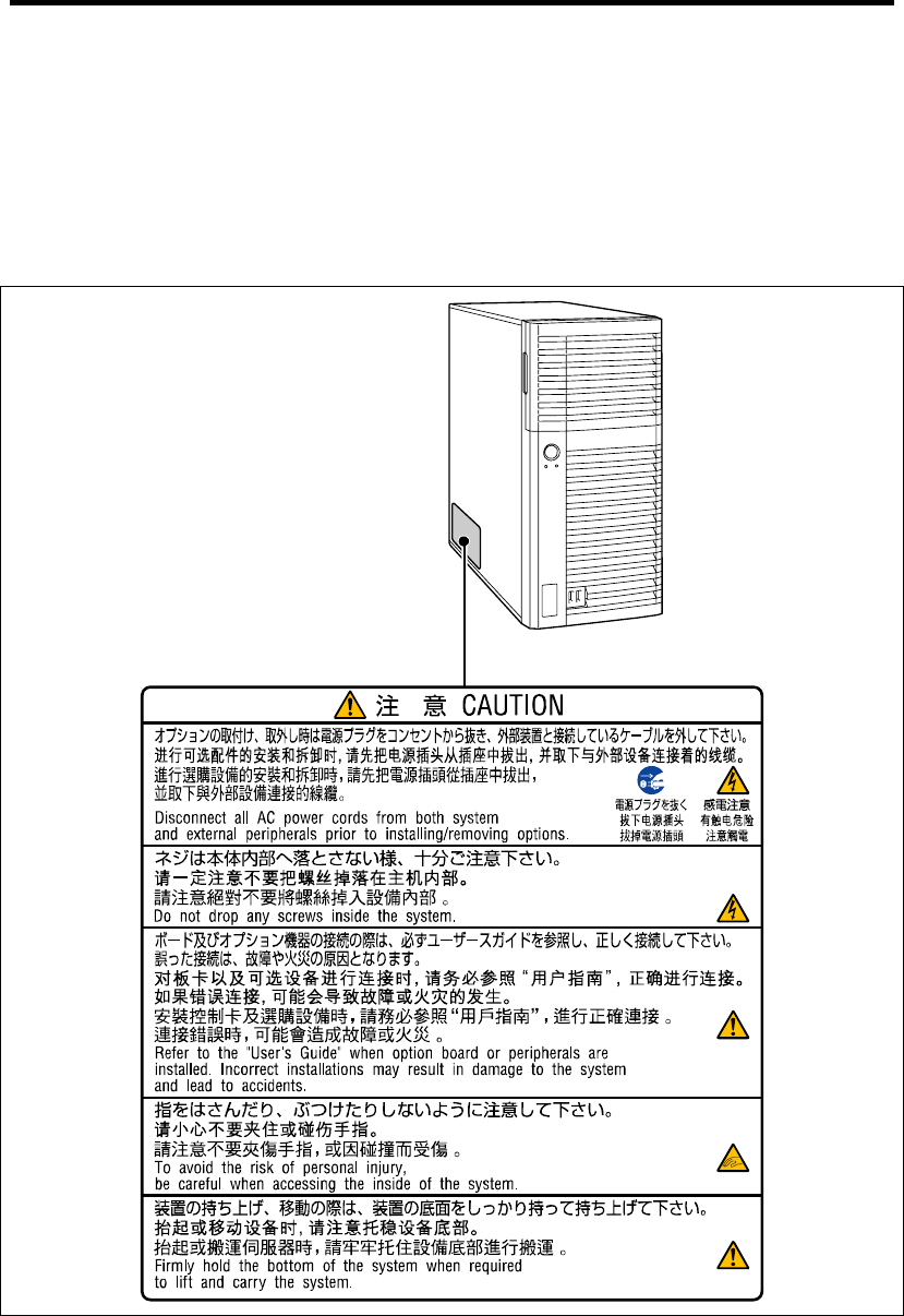
WARNING LABELS
The warning label is attached to components with possible danger or their vicinity in your server to
inform the user that a hazardous situation may arise when operating the server. (Do not intentionally
remove or damage any of the labels.)
If you find any labels totally/partially removed or illegible due to damage, contact your sales
representative.
Notes on Using Your Server 1-3
SAFETY NOTES
This section provides notes on using your server safely. Read this section carefully to ensure proper
and safe use of the server. For symbols, see "SAFETY INDICATIONS" provided earlier.
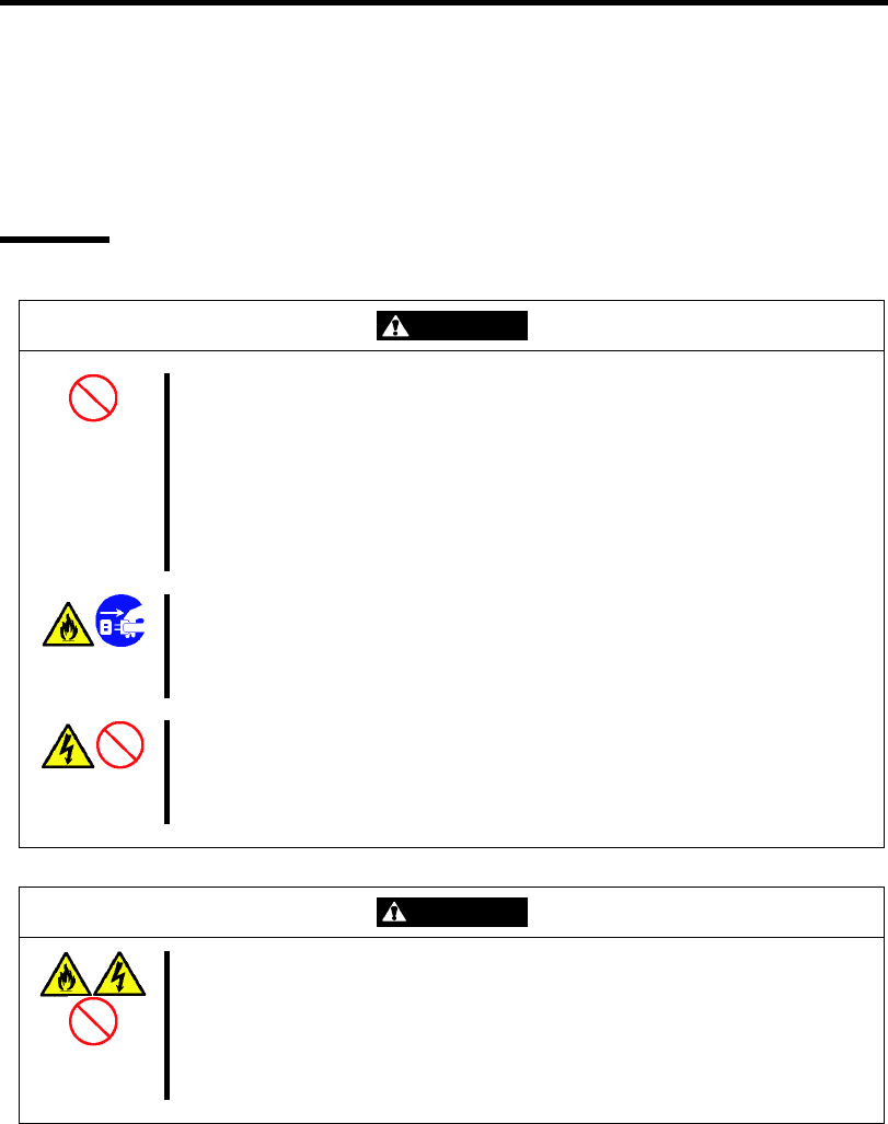
General
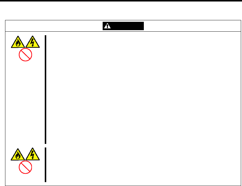
WARNING
Do not use the server for services where critical high availability may directly
affect human lives.
Your server is not intended to be used with or control facilities or devices
concerning human lives, including medical devices, nuclear facilities and
devices, aeronautics and space devices, transportation facilities and devices;
and facilities and devices requiring high reliability. NEC assumes no liability for
any accident resulting in personal injury, death, or property damage if the
server has been used in the above conditions.
Do not use the server if any smoke, odor, or noise is present.
If smoke, odor, or noise is present, immediately turn off the server and
disconnect the power plug from the outlet, then contact your service
representative. Using the server in such conditions may cause a fire.
Keep needles or metal objects away from the server.
Do not insert needles or metal objects into ventilation holes in the server or
openings in the floppy disk or optical disk drive. Doing so may cause an electric
shock.
CAUTION
Keep water or foreign matter away from the server.
Do not let any form of liquid (water etc.) or foreign matter (e.g., pins or paper
clips) enter the server. Failure to follow this warning may cause an electric
shock, a fire, or a failure of the server. When such things accidentally enter the
server, immediately turn off the power and disconnect the power plug from the
outlet. Do not disassemble the server. Contact your service representative.
1-4 Notes on Using Your Server
Power Supply and Power Cord Use
WARNING
Do not hold the power plug with a wet hand.
Do not disconnect/connect the plug while your hands are wet. Failure to follow
this warning may cause an electric shock.
Do not connect the ground wire to a gas pipe.
Never connect the ground wire to a gas pipe. Failure to follow this warning may
cause a gas explosion.
CAUTION
Plug in to a proper power source.
Use a proper wall outlet of the specified voltage. Use of an improper power
source may cause a fire or a power leak.
Do not install the server where you need an extension cord. Use of a cord that
does not meet the power specifications of your server may heat up the cord and
cause a fire.
Do not connect the power cord to an outlet that has an illegal number of
connections.
The electric current exceeding the rated flow overheats the outlet, which may
cause a fire.
Do not pull the cable when disconnecting it.
When disconnecting the cable from the device, hold the cable connector and
pull it straight out. Pulling the cable out by the cable portion or giving
mechanical stress to the connector could damage the cables and connectors to
result in an electrical shock hazard or a fire.
Insert the power plug into the outlet as far as it goes.
Heat generation resulting from a halfway inserted power plug (imperfect
contact) may cause a fire. Heat will also be generated if condensation is formed
on dusty blades of the halfway inserted plug, increasing the possibility of fire.
Notes on Using Your Server 1-5
CAUTION
Use the authorized power cord only.
Use only the power cord that comes with your server. Use of an unauthorized
power cord may cause a fire when the electric current exceeds the rated flow.
Also, observe the following to prevent an electric shock or fire caused by a
damaged cord.
Do not stretch the cord harness.
Do not pinch the power cord.
Do not bend the power cord.
Keep chemicals away from the power cord.
Do not twist the power cord.
Do not place any object on the power cord.
Do not bundle power cords.
Do not alter, modify, or repair the power cord.
Do not secure the power cord with staples or equivalents.
Do not use any damaged power cord. (Replace a damaged power cord with
a new one of the same specifications. Ask your service representative for
replacement.)
Do not use the attached power cord for any other devices or usage.
The power cord that comes with your server is designed aiming to connect with
this server and to use with the server, and its safety has been tested. Do not
use the attached power cord for any other purpose. Doing so may cause a fire
or an electric shock.

1-6 Notes on Using Your Server
Installation, Relocation, Storage, and Connection
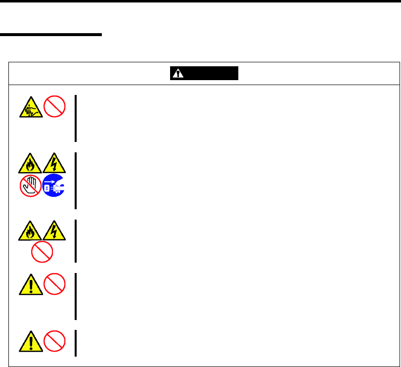
CAUTION
Do not hold the front bezel to lift the server.
Do not hold the front bezel to lift the server. The front bezel may be disengaged
from the server, causing personal injury. Hold the server firmly by its bottom.
Do not install the server in any place other than specified.
Do not install the server in the following places or any place other than specified
in this manual. Failure to follow this instruction may cause a fire.
a dusty place
a humid place such as near a boiler
a place exposed to direct sunlight
an unstable place
Do not use the server in the place where corrosive gases exist.
Make sure not to locate or use the server in the place where corrosive gases
(sulfur dioxide, hydrogen sulfide, nitrogen dioxide, chlorine, ammonia, ozone,
etc.) exist.
Also, do not set it in the environment where the air (or dust) includes
components accelerating corrosion (ex. sulfur, sodium chloride) or conductive
metals. There is a risk of a fire due to corrosion and shorts of an internal printed
board.
Do not connect any interface cable with the power cord of the server plugged to
a power source.
Make sure to power off the server and unplug the power cord from a power
outlet before installing/removing any optional internal device or
connecting/disconnecting any interface cable to/from the server. If the server is
off-powered but its power cord is plugged to a power source, touching an
internal device, cable, or connector may cause an electric shock or a fire
resulted from a short circuit.
Do not use any unauthorized interface cable.
Use only interface cables provided by NEC and locate a proper device and
connector before connecting a cable. Using an authorized cable or connecting
a cable to an improper destination may cause a short circuit, resulting in a fire.
Also, observe the following notes on using and connecting an interface cable.
Do not use any damaged cable connector.
Do not step on the cable.
Do not place any object on the cable.
Do not use the server with loose cable connections.
Notes on Using Your Server 1-7
Cleaning and Working with Internal Devices
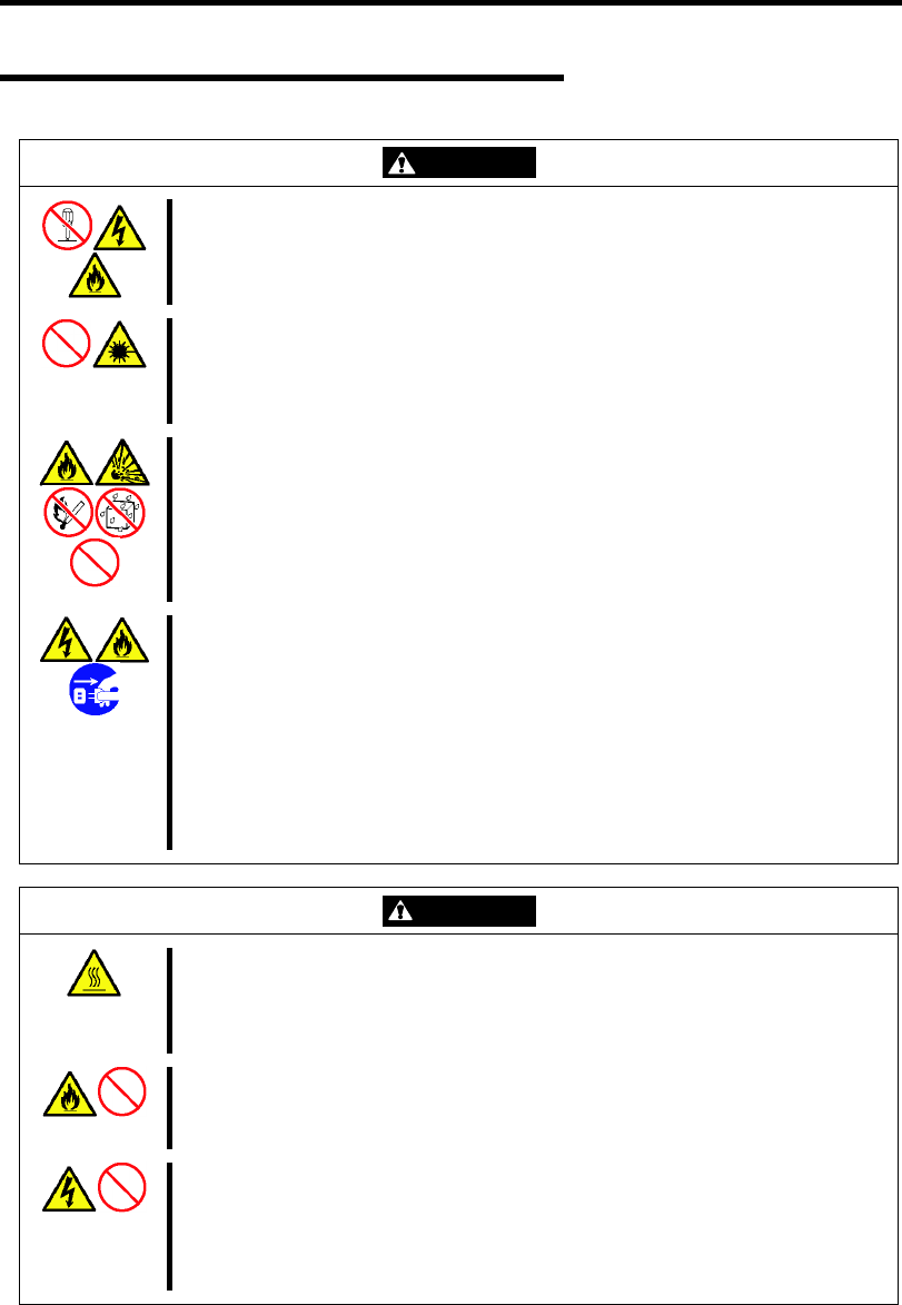
WARNING
Do not disassemble, repair, or alter the server.
Never attempt to disassemble, repair, or alter the server on any occasion other
than described in this manual. Failure to follow this instruction may cause an
electric shock or fire as well as malfunctions of the server.
Do not look into the optical disk drive.
A laser beam used in the optical disk drive is harmful to the eyes. Do not look
into or insert a mirror into the drive while the drive is powered. If a laser beam is
caught in your eyes, you may lose your eyesight (the laser beam is invisible).
Do not remove the lithium battery.
Your server contains the lithium battery. Do not remove the battery. Placing the
lithium close to a fire or in the water may cause an explosion.
When the server does not operate appropriately due to the dead lithium battery,
contact your service representative. Do not disassemble the server to replace
or recharge the battery by yourself.
Disconnect the power plug before accessing inside the server, or connecting
the peripherals.
Make sure to power off the server and disconnect the power plug from a power
outlet before cleaning or installing/removing internal optional devices. Touching
any internal device of the server with its power cord connected to a power
source may cause an electric shock even of the server is off-powered.
Disconnect the power plug from the outlet occasionally and clean the plug with
a dry cloth. Heat will be generated if condensation is formed on a dusty plug,
which may cause a fire.
CAUTION
Avoid installation in extreme temperature conditions.
Immediately after the server is powered off, its internal components such as
hard disk drives are very hot. Leave the server until its internal components fully
cool down before installing/removing any component.
Make sure to complete board installation.
Always install a board firmly. An incompletely installed board may cause a
contact failure, resulting in smoking or fire.
Protect the unused connectors with the protective cap.
The unused power supply cable connectors are covered with the protective cap
to prevent short circuits and electrical hazards, when removing the power
supply cable connector from the install devices, attach the protective cap to the
connector. Failure to follow this warning may cause a fire or an electric shock.
1-8 Notes on Using Your Server
During Operation
CAUTION
Stay away from the fan.
Keep your hand or hair away from the cooling fan on the rear of the server.
Failure to follow this warning may get your hand or hair caught in the fan,
resulting in injury.
Avoid contact with the server during thunderstorms.
Disconnect the power plug from the outlet when a thunderstorm is approaching.
If it starts thundering before you disconnect the power plug, do not touch any
part of the server including the cables. Failure to follow this warning may cause
a fire or an electric shock.
Keep animals away from the server.
Failure to follow this warning may cause a fire or an electric shock.
Do not leave the CD tray open.
If dust gets on the lens of optical disk drive, the drive may have problems
reading your disks.
Also, the CD tray may be broken by contacting any objects.
Do not place any object on top of the server.
The server may fall and cause property damage to the surroundings.

Notes on Using Your Server 1-9
FOR PROPER OPERATION
Observe the following notes for successful operation of the server. Use of the server ignoring the
notes will cause malfunctions or failures of the server.
Install the server in a place that meets requirements for successful operation. For details,
see Chapter 3, "Setting Up Your Server."
If the power cord supplied with your system is not compatible with the AC wall outlet in
your region, contact your service representative to obtain a suitable power cord.
Make sure to power off the server before connecting or disconnecting cables between the
server and peripheral devices.
Verify that the access lamp on the server is unlit before turning off the server or ejecting
the floppy disk.
When plugging the power cord to the system, you may experience 10 seconds delay from
the time you press the POWER/SLEEP switch on the front panel. This is normal system
operation.
When you have just turned off the server, wait at least 10 seconds before turning it back
on. If the server is connected to the UPS, set at least 10 seconds delay in the power-on
schedule.
For the disk which does not conform to the CD standard, the playback of such a disk with
the CD drive is not guaranteed.
Turn off the power and unplug the power cord from the outlet before relocating the server.
Clean the server on a regular basis. (See Chapter 7 for cleaning.) Regular cleaning
proactively prevents various failures of the server.
Lightning may cause a momentary voltage drop. To prevent this problem, it is
recommended to use of an uninterruptible power supply unit.
Make sure to use optional devices supported by the server. Some non-supported devices
may be physically installed/connected but cause failures of the server as well as
malfunctions of the server.
NEC recommends you use NEC's genuine products. Some third-party products claim that
they support the server. However, repair of the server due to a failure or damage resulted
from use of such third-party products will be charged.
Turn off the cellular phone or pager. Radio interference may cause malfunctions of the
server.

1-10 Notes on Using Your Server
TRANSFER TO THIRD PARTY
The following must be observed when you transfer (or sell) the server or software provided with the
server to a third party:
Make sure to provide this manual along with the server to a third party.
IMPORTANT: About data on the hard disk drive
Be sure to take appropriate measures not to leak important data (e.g.,
customers' information or companies' management information) on the
removed hard disk drive to any third parties.
Data seems to be erased when you empty "Recycle Bin" of Windows or
execute the "format" command of the operating system. However, the
actual data remains written on the hard disk drive. Data not erased
completely may be restored by special software and used for
unexpected purposes.
It is strongly recommended that the software or service (both available
at stores) for data erasure should be used in order to avoid the trouble
explained above. For details on data erasure, ask your sales
representative.
Provided software
To transfer or sell any software application that comes with the server to a third party, the following
requirements must be satisfied:
All provided software applications must be transferred and no backup copies must be
retained.
Transfer requirements listed in "Software License Agreement" that comes with each
software application must be satisfied.
Software applications that are not approved for transfer must be uninstalled before
transferring the server.

Notes on Using Your Server 1-11
DISPOSAL AND CONSUMABLES
Dispose of the server, all the internal devices, floppy disks, CD-ROMs, and batteries
according to all national laws and regulations.
IMPORTANT: It is the user's responsibility to completely erase or
modify all the data stored in storage device such as hard disk drive so
that the data cannot be restored.
Your server contains some components that are only good for a limited period of time and
require replacement, such as fans, internal batteries, the internal optical disk drive, the
floppy disk drive, and the mouse. For stable operation of the server, NEC recommends
you replace these components on a regular basis. Consult with your service representative
for replacement or the product lives.
REGARDING THE TRANSPORTATION OF THIS SYSTEM
This system and/or associated options and accessories may be using lithium metal batteries or
lithium ion batteries.
There may be restrictions regarding the air or sea transportation of such lithium batteries.
Please contact your service representative prior to transporting this system and/or its options.
USER SUPPORT
Before Asking for Repair, do the following when the server appears to fail:
1. Check if the power cord and the cables to other devices are properly connected.
2. See Chapter 8 to find if your problem fits the description. If it does, take the
recommended measure for it.
3. Check if the software required for operation of the server is properly installed.
If the server still appears to fail after you have taken the above actions, consult with your service
representative immediately. Take notes on lamp indications of the server and alarm indications on
the display unit before consultation, which may provide a significant help to your service
representative.
USE OF THE TERM “OPTICAL DISK DRIVE”
This equipment includes one of the drives below. In this document, this drive is referred to as the
"optical disk drive".
DVD-ROM drive
DVD super multi drive

1-12 Notes on Using Your Server
Note that the operation is not guaranteed when attempting use a CD playback device to play back a
disc that does not comply with the CD standards, such as a copy-protected CD.
USE OF THE TERM “HARD DISK DRIVE”
Unless otherwise specified, the term hard disk drive (HDD) when used in this document refers to
the following:
Hard disk drive (HDD)
Solid state drive (SSD)
Notes on Using Your Server 1-13
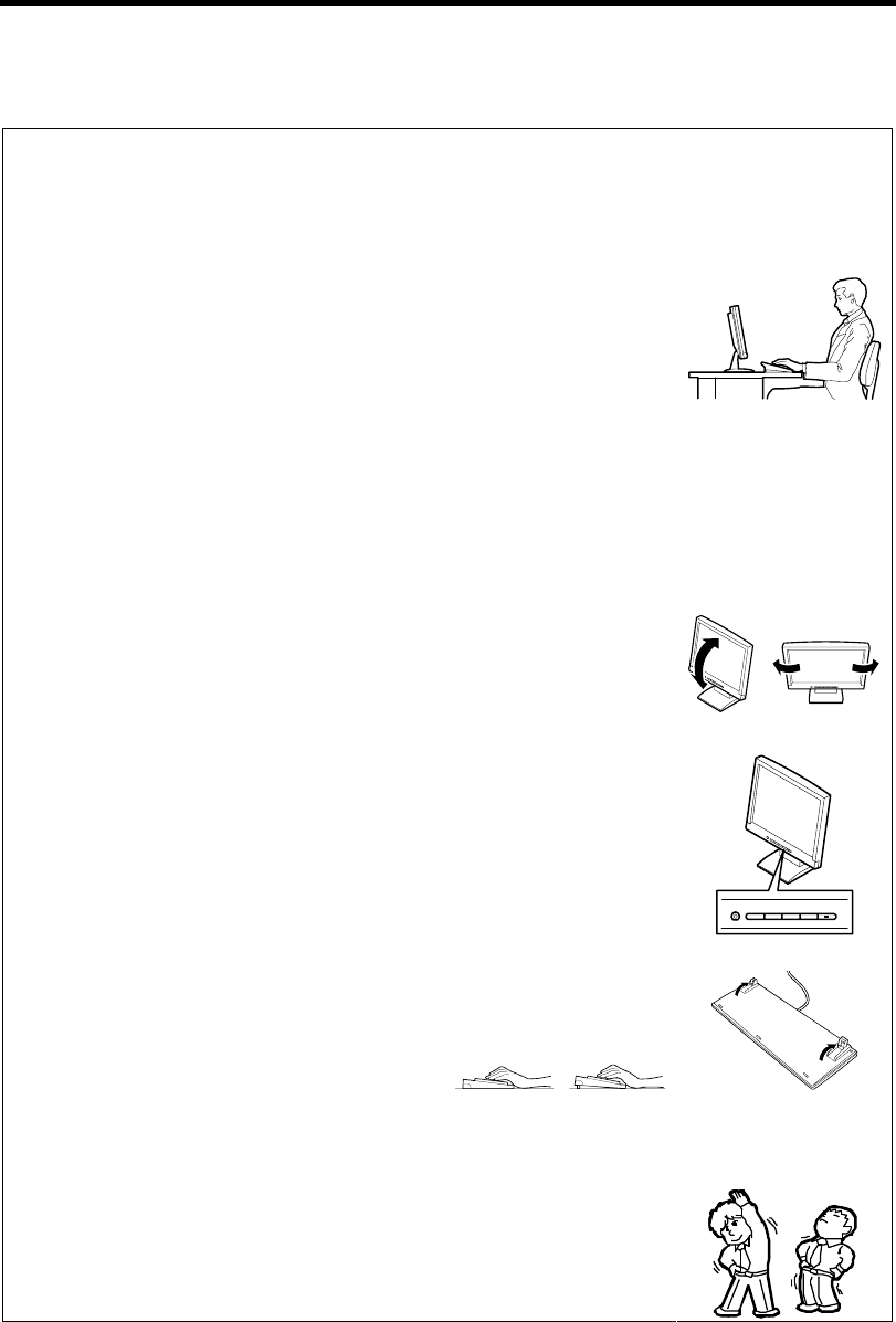
Advice for Health
The longer you keep using the computer equipment, the more you
become tired, which may cause disorders of your body. When you use a
computer, observe the following to keep yourself from getting tired:
Good Working Posture
You have good posture if the following are satisfied when you use a
computer:
• You sit on a chair with your back straight.
• Your hands are parallel with the floor when you put them on the
keyboard.
• You look at the screen slightly lower than your eye height.
You have "good working posture" as described in the above when no part
of your body is under excess strain, in other words when your muscles
are most relaxed.
You have "bad posture" when you sit with your back hunched up or you
operate a display unit with your face close to the screen. Bad working
posture may cause eye strain or poor eyesight.
Adjustment of Display Unit Angles
Most display units are designed for adjustment of the horizontal and
vertical angles. This adjustment is important to prevent the screen from
reflecting bright lights and to make the display contents easy to see. You
will not be able to keep "good working posture" and you will feel more
tired than you should if you operate a display unit without adjusting
horizontal and vertical angles.
Adjustment of Screen Brightness and Contrast
The display unit has brightness and contrast adjustment functions. The
most suitable brightness and contrast depend on the individual and the
working environment (well-lighted room or insufficient light). Adjust
brightness and contrast so that the screen will be easy to see. An
extremely bright or dark screen will give a bad effect to your eyes.
Adjustment of Keyboard Angle
The keyboard provided with the server is designed for adjustment of an
angle. Adjust the keyboard angle at which the keyboard is easy to
operate. The adjustment assists in reducing strain on your shoulders,
arms, and fingers.
Cleaning of Equipment
Clean equipment regularly. It is difficult to see the display contents on a
dusty screen. Keeping equipment clean is also important for your sight.
Fatigue and Rest
If you feel tired, you should stop working and do light exercises.

1-14 Notes on Using Your Server
(This page is intentionally left blank.)

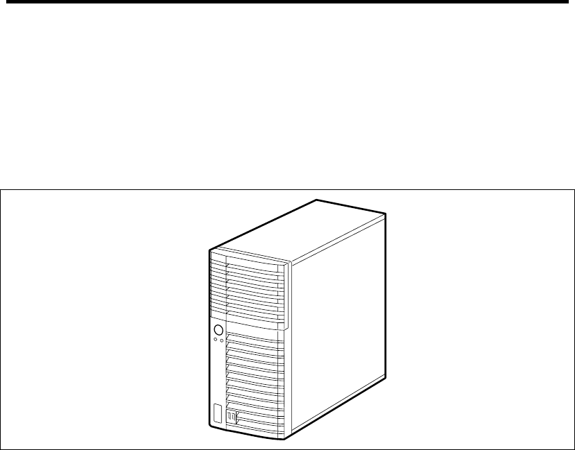
2-2 General Description
OVERVIEW
Your server is a modular, multiprocessing server based on the Intel microprocessor family. It is a
solid performer and offers the latest technology. The combination of compute performance, memory
capacity, and integrated I/O provides a high performance environment for many server market
applications. These range from large corporations supporting remote offices to small companies
looking to obtain basic connectivity capability such a file and print services, e-mail, web access,
web site server, etc. Your server is housed and available as a tower-based system.
Front View
As application requirements increase, you can expand your server with an additional memory,
add-in boards and peripheral devices; tape devices, DVD-ROM, and hard disk drives. The server
features the following major components.
A high-performance Intel® Xeon® Processor, Intel® Pentium® Processor, or Intel®
Celeron® Processor
Up to 16GB of memory (using 4GB DIMMs)
Minimum configuration is 1GB of memory
Dual channel memory configuration
Four integrated I/O expansion PCI-e/PCI-X slots for add-in boards (three PCI EXPRESS
slots and one 32-bit/33 MHz slot)
Onboard enhanced serial ATA RAID Controller
Onboard 1000/100/10 network controller
Integrated optical disk drive
Four hard disk drive slots
Embedded PC-compatible support (serial, mouse, keyboard, USB, LAN, and video)
High degree of SATA hard disk drive fault tolerance and advanced RAID management
features through the use of RAID Technology.
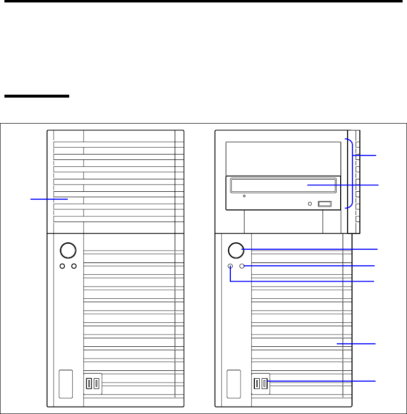
General Description 2-3
SYSTEM CHASSIS
Names and functions of the components are shown below.
Front View
1
1
2
4
3
7
6
5

2-4 General Description
1 Front bezel
Open the door when accessing the file bay.
Remove the front bezel when installing/removing the 5.25-inch device, optical disk drive,
and hard disk drives.
2 Front USB connector
Connect the USB device to this connector.
3 Optical disk drive
The optical disk drive reads data from the inserted CD-ROM or DVD-ROM.
The drive is equipped with the following:
• Open/Close button to eject the tray
• Access lamp that indicates the disk access status
• Emergency hole to forcibly eject the tray
4 5.25-inch device bay
One backup file devices of 5.25-inch width such as DAT drive or MO drive may be installed
in the 5.25-inch device bay. An optical disk drive is factory-installed on the bottom of bay.
The bay is equipped with an EMI bracket.
5 Disk access lamp (green)
The disk access lamp is lit while the system accesses to a built-in hard disk drive or optical
disk drive. If the built-in hard disk drive is connected to the proper optional board, this lamp
can be lit only when the LED cable provided with the system is connected.
6 POWER/SLEEP lamp (green)
Lights in green when the server is powered on.
Blinks when the system is placed in the sleep Mode.
7 POWER/SLEEP switch
The POWER/SLEEP switch is used to turn the power of the server ON/OFF. If you press
this switch once, the power is turned on with the POWER/SLEEP lamp going on green. If
you press the switch again, the power is turned off.
Some OS setting can provide the function of switching to the power saving (sleep) mode. If
you press the POWER/SLEEP switch once after the setting, the system is entered into the
power saving mode with the POWER/SLEEP lamp blinking green. If you press the switch
again, the system is returned to the normal state. (Depending on installed optional boards,
the function cannot be provided.)
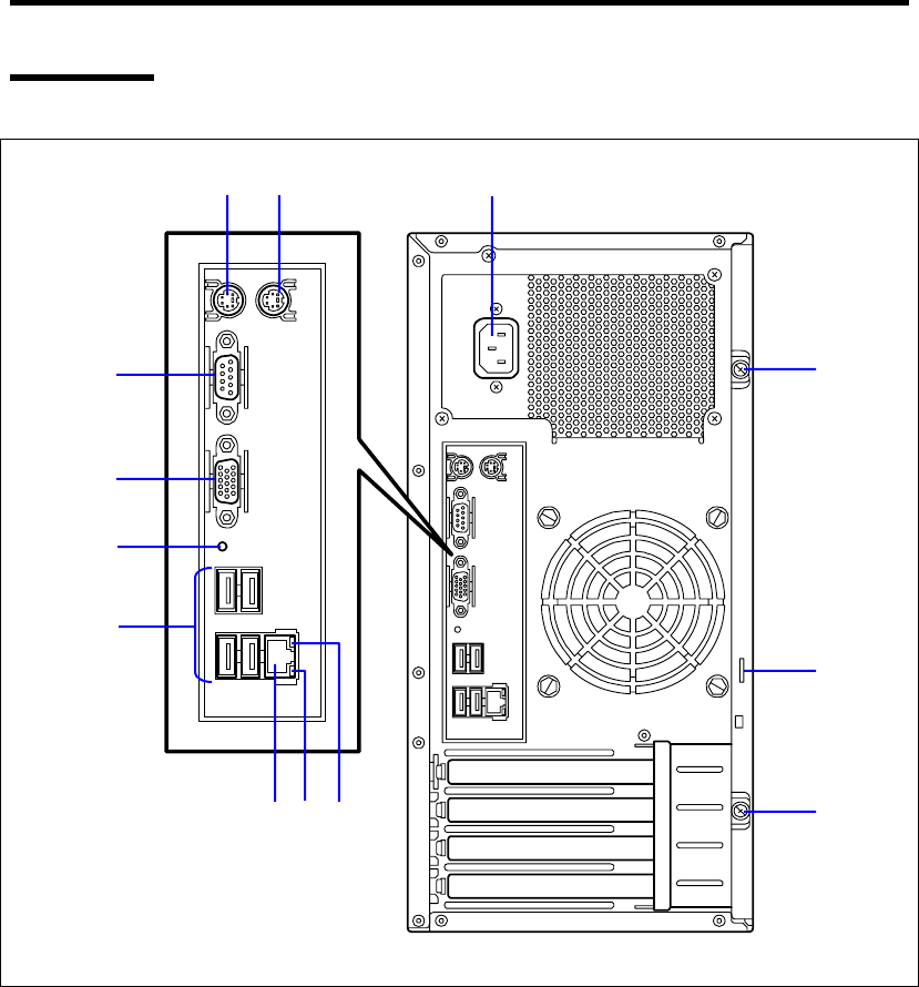
General Description 2-5
Rear View
14 5
7
8
12
6
9 11 10
2
3
2
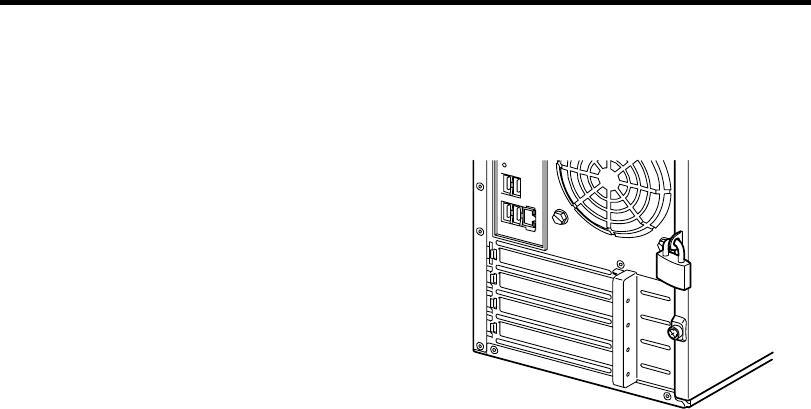
2-6 General Description
1 AC inlet
The AC inlet is connected with the power cord.
2 Fixing screws
Secures the side cover.
3 Cover lock plate
Installing a theft prevention device protects
the internal components of the server from
being stolen.
4 Mouse connector
The mouse connector is connected with the mouse coming with the server.
5 Keyboard connector
The keyboard connector is connected with keyboard coming with the server.
6 USB connectors
The USB connectors are connected with devices accepting the USB interface.
7 Serial port A connector
The serial port connector is used to connect the server to a device with the serial interface.
The server cannot be directly connected to a leased line through the connector.
Note: If N8117-01A is connected, the connector on N8117-01A side becomes serial port B
connector.
8 Display connector
The display connector is connected with the display unit.
9 LAN connector
The LAN connector is connected with a network system on LAN
(1000BASE-T/100BASETX/10BASE-T).
10 Link/ACT lamp
The Link/ACT lamp shows the LAN access status.
11 1000/100/10 lamp
1000/100/10 lamp indicates the LAN transfer rate.
12 Dump switch
Press this switch when collecting memory dump.
NOTE: Consult with your service representative before collecting memory dump. Collecting
memory dump while the server is in the successful operation may affect the system
operation.
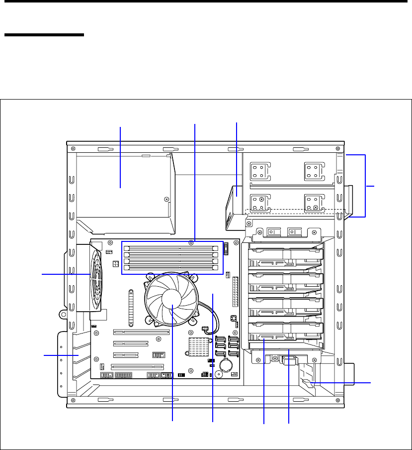
General Description 2-7
Internal View
Low-power CPU model (N8100-1592F/1593F) when optional 3.5-inch hard
disk drive cage is installed
1 Power supply
2 DIMM slots
3 Optical disk drive
4 5.25-inch device bay
An optical disk drive is factory installed in bottom bay.
5 PCI guide rail
6 Hard disk drive cage
7 Hard disk drive (optional)
8 Mother board
9 Processor cooling fan
10 PCI board retention spring
11 Rear cooling fan
1
11
10
4
5
23
9 8 7 6
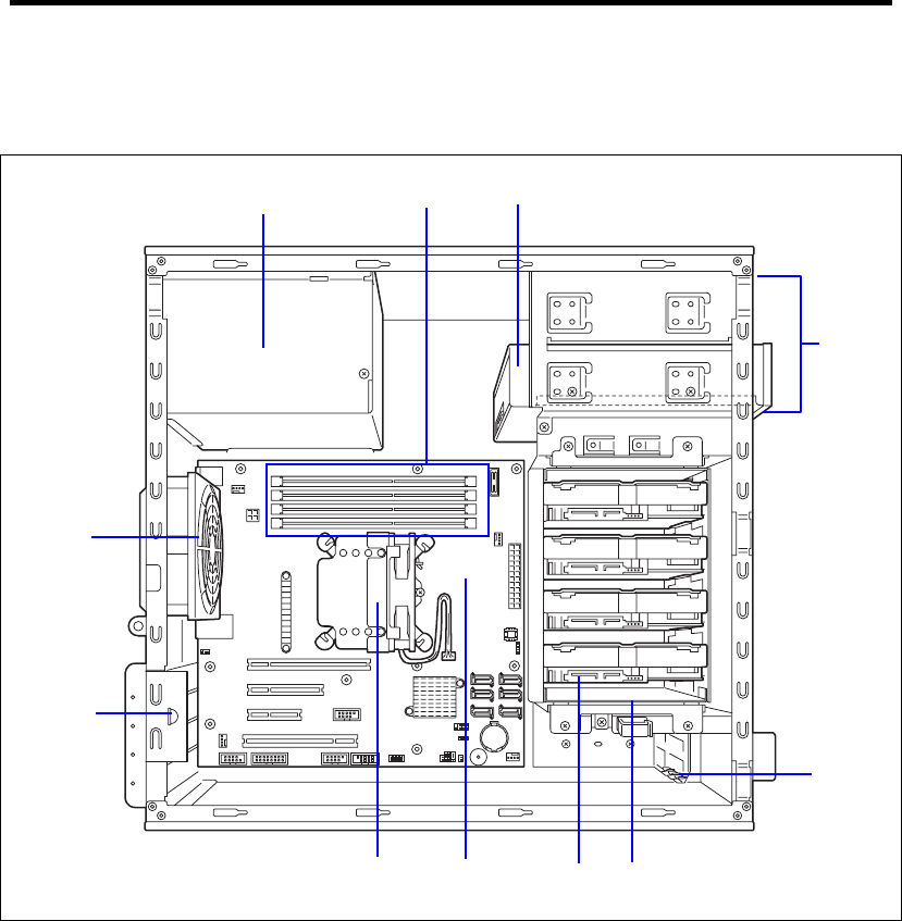
2-8 General Description
High-power CPU model (N8100-1594F) when optional 3.5-inch hard disk drive
cage is installed
1 Power supply
2 DIMM slots
3 Optical disk drive
4 5.25-inch device bay
An optical disk drive is factory installed in bottom bay.
5 PCI guide rail
6 Hard disk drive cage
7 Hard disk drive (optional)
8 Mother board
9 Processor cooling fan
10 PCI board retention spring
11 Rear cooling fan
1
11
10
4
5
2 3
9876

General Description 2-9
When optional 2.5-inch hard disk drive cage is installed
1 Power supply
2 DIMM slots
3 Optical disk drive
4 5.25-inch device bay
An optical disk drive is factory installed in bottom bay.
5 PCI guide rail
6 Hard disk drive cage
7 Hard disk drive (optional)
8 Mother board
9 Processor cooling fan
10 PCI board retention spring
11 Rear cooling fan
1
11
10
4
5
23
9 8 7 6
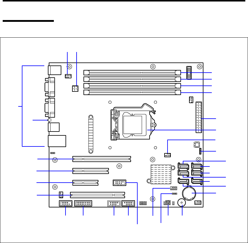
2-10 General Description
Mother Board
1 DIMM sockets 12 USB connector (for flash memory
card)
(The last digit indicates connector number.) 13 USB connector (for front USB port)
2 Power connector 14 USB connector (for device bay)
3 CPU socket 15 LED/SW connector
4 FAN1 connector (for CPU cooling fan) 16 COM B connector for N8117-01A
5 RAID LED cable connector 17 PCI board slots
6 Serial ATA connectors #0 to #5 17-1: PCI EXPRESS x16
(The last digit indicates connector number.) 17-2: PCI EXPRESS ×4 (x8 connector)
7 Lithium battery 17-3: PCI EXPRESS ×2 (x4 connector)
8 Buzzer 17-4: PCI 32bit/33 MHz
9 CMOS configuration jumper switch 18 DUMP switch
10 RAID configuration jumper switch 19 Connectors for external devices
11 SGPIO connector 20 FAN2 connector (for rear cooling fan)
1-2
1-4
1-1
1-3
2
3
4
5
6-0
6-2
6-4
6-1
6-3
6-5
7
89
10
111314
12
1516
17-4
17-3
17-2
17-1
18
19
20 2
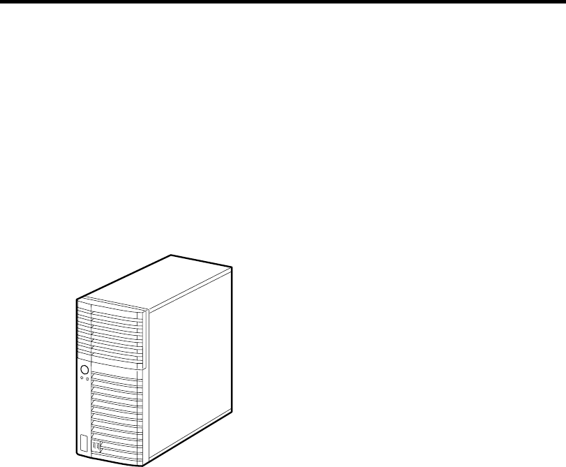
General Description 2-11
STANDARD FEATURES
High performance Expandability
Intel® Xeon® Processor
Intel® Pentium® Processor
Intel® Celeron® Processor
High-speed
1000BASE-T/100BASE-TX/10BASE-T
interface (1Gbps/100Mbps/10Mbps
supported)
High-speed disk access
(SATA (standard) and SAS (option))
Dual channel memory configuration
Four integrated I/O expansion PCI slots
– PCI EXPRESS (x16): 1 slot
– PCI EXPRESS (x4): 1 slot
(connector: x8)
– PCI EXPRESS (x2): 1 slot
(connector: x4)
– PCI bus (32-bit/33MHz): 1 slot
Large memory of up to 16GB
(four 4GB DIMMs)
USB interface (USB 2.0)
High-reliability Many Available Features
El Torito Bootable CD-ROM (no emulation
mode) format support
Remote power-on feature
AC-LINK feature
Onboard RAID Controller (SATA)
Self-diagnosis
Memory monitoring feature (error
correction/error detection)
Temperature detection
Cooling fan monitoring feature
Voltage monitoring feature
BIOS password feature
RAID System
(SATA (standard) and SAS (option)) Power On Self-Test (POST)
Test and Diagnosis
Management Utilities Easy and Fine Setup
NEC ESMPRO
Off-line Maintenance Utility
RAID System Management Utility
ExpressUpdate feature
New management function
Hardware events can be logged.
NEC EXPRESSBUILDER (system setup
utility)
BIOS SETUP utility
Parameter File Creator
Power Saving Feature Quietness
Sleep feature
(available for Windows Server 2003 or
later)
The fan can be set to low-speed mode for
quieter operation
High availability
A watchdog timer monitors for stalls.

2-12 General Description
Remote Power-On Feature (Wake On LAN)
The remote power-on function turns on the server through a network. It sends a special packet from
the management computer to a remote server to turn it on if the server is off-powered.
To enable this feature, you must select "Enabled" for each submenu in the Power Management
Setup of the Advanced menu of the BIOS SETUP utility. (See Chapter 4.)
The remote power-on feature is not available in the following cases. Press the POWER/SLEEP
switch once to start the OS, and turn off the server in an appropriate procedure.
Abnormal previous system shut-down
No power supply to the server (due to turned-off breaker, disconnected power cord, power
blackout, etc.)
AC LINK Feature
When the power cord of the server is connected to an uninterruptible power supply (UPS) unit, the
server supports the power linkage feature that enables control over the power supply from the UPS
to the server. The AC LINK feature can be enabled or disabled with Power Management Setup in
the Server menu of the BIOS SETUP utility. (See Chapter 4.)
Security
The BIOS SETUP utility provides a number of security features to prevent unauthorized or
accidental access to the system. Once the security measures are enabled, access to the system is
allowed only after the user enters the correct password(s). For example:
Set and enable an administrative password.
Set and enable a user password
Check the user account when entering the BIOS SETUP utility or booting the system.

General Description 2-13
Running the Server with the Fan Set to Low-speed Mode
(Silent Mode)
The fan inside the server can be set to low-speed (silent mode) as follows, allowing the server to run
much more quietly.
Setting the fan to low-speed mode:
Make sure that there is no board in the PCI slot of the server.
Change the [Fan Control Mode] setting on the [Server] tab in the BIOS Setup utility from
[Normal] to [Low].
NOTE: If a board is inserted in the PCI slot, POST displays an error
on the screen and the fan operates in Normal mode when the server
starts up.
NEC EXPRESSBUILDER
The DVD-ROM that comes with the server contains a setup utility called "NEC
EXPRESSBUILDER."
The major functions of the NEC EXPRESSBUILDER are:
To install the Operating System.
"Express Setup" helps you to install the Windows Operating System. (See Chapter 5.)
To diagnose the system.
NEC EXPRESSBUILDER includes the System Diagnostics to check your server. (See
Chapter 6.)
To create a support disk.
Use this function to create the support disks used to boot the utilities from the floppy disk,
or the OEM-disk used for a manual installation of Windows. (See Chapter 6.)
To update the BIOS.
Use this function to update the system BIOS or firmware of the server. (See Chapter 6.)
To update the Windows System*
"Update Express5800 system" in Windows Autorun Menu (Windows-based NEC
EXPRESSBUILDER feature) updates the several resources of Microsoft Windows Server
2003. (See Chapter 6.)
To install the utilities.
NEC EXPRESSBUILDER DVD includes some management software for Windows
(NEC ESMPRO, and so on).
You can install the applications for Windows from Windows Autorun Menu.
(See Chapter 6.)
To read the online documents*
You can refer to the online documents from Windows Autorun Menu. (See Chapter 6.)
* These functions are available under the Windows system.

2-14 General Description
NOTE: Some features among those listed above can be used from the
remote computer via cross cable (COM), or LAN. See Chapter 6 for
details.
NEC ESMPRO
The NEC ESMPRO is server management software that runs on the OS.
The NEC ESMPRO Manager is management software that enables you to manage and monitor the
servers remotely. To use this software, it is required to install appropriate bundled software on the
server.
NOTE: For details of major functions of the NEC ESMPRO, system
configuration and setups with the NEC ESMPRO, see Chapter 6.
Available functions of the NEC ESMPRO depend on the OS you install.
Ask your service representative for details.
Maintenance Tools
The Maintenance Tools is used for maintenance and fault analysis of the server. This tool is usually
used by the service representative.
System Diagnostic Utility
The system diagnostic utility contained in the NEC EXPRESSBUILDER is useful to detect
hardware failures. See Chapter 7 for details.
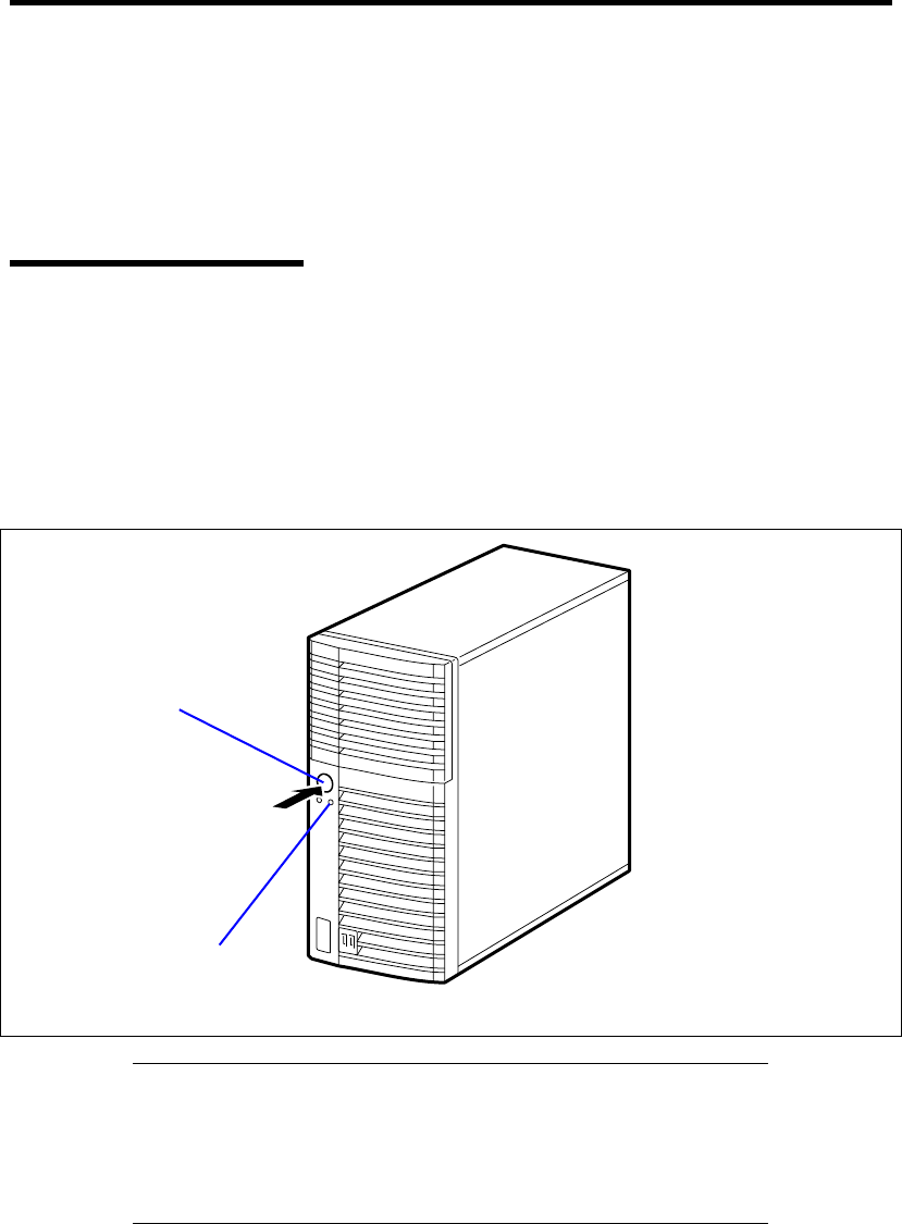
General Description 2-15
USING YOUR SERVER
This section describes basic operations of your server including how to use devices such as the
floppy disk drive and the optical disk drive. See Appendix B for notes on using the floppy disk,
CD-ROM, and accessories including the keyboard and the mouse.
POWER/SLEEP Switch
Use the POWER/SLEEP switch to turn on/off the server.
Power On
Press the POWER/SLEEP switch on the front of the server.
The POWER/SLEEP lamp lights in green.
IMPORTANT:
If the power cord is connected to a power control device such as a
UPS (Uninterruptible Power Supply), make sure that the power
control device is powered.
Do not turn off the server until characters appear on the screen.
POWER/SLEEP lamp
POWER/SLEEP switch

2-16 General Description
POST
POST (Power On Self-Test) is the self-diagnostic program stored in the system memory.
When you power on the server, the system automatically runs POST to check the mother board,
ECC memory module, CPU module, keyboard, and mouse. POST also displays messages of the
BIOS Setup utility, such as the start-up message, while in progress.
With the factory setup of the server, the NEC logo appears on the display unit while POST is in
progress. (To display the POST check results, press Esc.)
NOTE: You can set the POST check results to appear on the display
unit without pressing Esc. To do so, select "Enabled" for "Boot-time
Diagnostic Screen" under the Advanced menu of the BIOS SETUP
utility.
You don't always need to check the POST check results. Check messages that POST displays when:
you use the NEC Express server for the first time.
the server appears to fail.
the server beeps for many times between power-on and OS start-up.
an error message appears on the display unit.

General Description 2-17
POST Execution Flow
The following describes the progress of POST in the chronological order.
IMPORTANT:
Do not power off the server while POST is in progress.
Do not make key entries or perform mouse operations while POST
is in progress.
Some system configurations may display the message "Press Any
Key" to prompt a key entry. This message is driven by BIOS of an
installed optional board. Make sure to read the manual that comes
with the optional board before any key entry.
Powering on the server, after you installed or removed an optional
PCI board or moved it to another slot, may display the message that
indicates incorrect board configuration and suspend POST.
In such a case, press F1 to continue POST. Board configuration can
be made using the utility described later.
1. After a few seconds from power-on, POST starts checking the memory. The count
message of the basic and expansion memory appears at top left on the display unit screen.
The memory check may take a few minutes to complete depending on the memory size of
the server. Also, it may take approximately one minute for the screen display to appear
after rebooting the server.
2. Some messages appear upon completion of the memory check. These messages appear to
indicate that the system has detected the CPU, keyboard, and mouse.
3. After a few seconds, the following message appears at the bottom left of the screen
prompting you to launch the SETUP utility stored in the BIOS chip on the motherboard.
To launch the SETUP utility, press F2 while the above message is displayed.
Message displayed when the NEC logo appears:
Press <F2> to enter SETUP or Press <F12> to Network
Message displayed when the POST screen appears:
Press <F2> to enter SETUP <F10> Boot menu <F12> to boot from
Network
Launch the SETUP utility only when you need to change the settings to meet the
requirements of the server environment. As long as the above message is not accompanied
by an error message, you do not have to change the settings. (Ignore the message. POST
will continue a few seconds later.)
See Chapter 4 for setup and parameters.

2-18 General Description
4. If your server uses Onboard RAID Controller, the following message is displayed to
prompt you to run RAID utility.
Press <Ctrl><M> to Run LSI SoftwareRAID Configuration Utility
Press Ctrl + M to run the utility. For detail explanation, see Chapter 4 for details.
IMPORTANT: The LSI Software RAID Configuration Utility is used
to manage the data stored in hard disk drive, or for maintenance. See
Chapter 4 for detail.
5. If the POST detects the optional add-in card, it displays the message prompting you to
launch the add-in card BIOS configuration utility. (Ignore the message. POST will
automatically proceed a few seconds later.)
Refer to the manual that comes with the optional add-in card for detail.
6. If you set a password entry using the BIOS SETUP utility, the password entry screen
appears upon successful completion of POST.
Up to three password entries will be accepted. Three incorrect password entries disable
the server to boot. In such a case, turn off the power and wait about ten seconds before
turning on to boot the server.
IMPORTANT: Do not set a password before installing an OS.
7. The OS starts when POST completes.
POST Error Messages
When POST detects an error, it displays an error message on the display unit screen or emits beep
code. See Chapter 8 for POST error codes.
IMPORTANT: Take a note on the messages displayed before
consulting with your sales agent. Alarm messages are useful
information for maintenance.

General Description 2-19
Power Off
Follow the procedure below to power off the server. If the power cord of the server is connected to a
UPS, refer to the manual that comes with the UPS or the manual for the application that controls the
UPS.
IMPORTANT: Always allow POST to complete before turning off the
server.
8. Shut down the OS.
9. Press the POWER/SLEEP switch on the front of the server.
The POWER/SLEEP lamp goes out.
10. Power off peripheral devices.
SLEEP Switch
The POWER/SLEEP switch allows you to save almost all power of the server (power-saving mode
or sleep mode).
Press the POWER/SLEEP switch on the front of the server to place the server in the power-saving
mode. (The POWER/SLEEP lamp blinks.) In the power-saving mode, the server retains the memory
data and the status of the previous operations.
To resume the original state, press the POWER/SLEEP switch again. (It may take a little time to
resume the original state.)
NOTE: The operational level in the power-saving mode depends on
the OS in use. (Available for Windows Server 2003.)
IMPORTANT: Do not change system configuration while turning into
the power-saving mode or in the power-saving mode. Otherwise, you
may fail to resume the original state.
2-20 General Description
Optical Disk Drive
The optical disk drive is installed in the front of the server. One of the following optical disk drives
can be used.
DVD-ROM drive (factory-installed)
Reads data from various optical disks.
DVD Super MULTI drive (option)
Reads or writes data of various optical disks.
CAUTION
Observe the following instructions to use the server safely. Failure to follow
these instructions may cause a fire, personal injury, or property damage. See
pages 1-2 to 1-11 for details.
Do not leave the tray ejected from the optical disk drive.
Precautions
Observe the following instructions when using the server. The server itself or your property (data
and other devices) might be destroyed if you use the server disregarding these instructions.
Use of the Optical Disk
Keep the following notes in mind to use the optical disk for the server:
For the disk which does not conform to the CD standard, the playback of such a disk with
the optical disk drive is not guaranteed.
Do not drop the optical disk.
Do not place anything on the optical disk or bend the optical disk.
Do not attach any label onto the optical disk.
Do not touch the signal side (nothing is printed on this side) with your hand.
Place the optical disk with its printed side upward and gently put it on the tray.
Do not scratch the optical disk or write anything directly on it with a pencil or ball-point
pen.
Keep the optical disk away from cigarette smoke.
Do not leave the optical disk in a high-temperature place (e.g., place exposed to direct
sunlight or close to a heater).
When dust or fingerprints are attached on the optical disk, wipe the optical disk from its
center to edge with a dry soft cloth slowly and gently.
Use the dedicated cleaner to clean the optical disk. Do not use record spray/cleaner,
benzene, or thinner.

General Description 2-21
Keep the optical disk in an optical disk case when not in use.
Use a non-printable disk recommended in the User's Guide of the server and/or the device.
Optical disk is a data storage media with delicate structure and requires care. Clean the
tray and optical regularly according to "Cleaning Disc" in Chapter 7.
Writing Data onto Disk
After writing the data onto disk, be sure to perform data compare process.
An operator should always be concerned with data writing (unattended writing should not
be performed).
Handling of Optical Disk Drive
Do not leave the tray ejected from the optical disk drive.
Do not leave the drive with an optical disk being contained.
Clean the disk and drive in regular basis. For the slim type drive, be careful not to touch
the lens while cleaning the drive.
Make sure that the drive works normally by reading a disk such as NEC
EXPRESSBUILDER.
About Write Error
A write error might occur when writing a data by using the optical disk drive due to the operating
environment or characteristics of disk, etc.
If a write error occurs even after the cleaning, try another disk.
Before Writing onto Disk
It is prohibited by the law to reproduce audio CD and the application without the
permission of the writer except for the personal use.
The data stored in DVD-R, DVD+R, or CD-R may be destroyed partially or entirely due
to write error. To prevent the data loss, observe the following instructions.
– Quit the program including an application software that might consume a large amount
of memory.
– Disable the screen saver utility.
– Quit the program to check the disk such as virus checker or system agency.
– Disable the utility that might start during writing, such as scheduler or timer.
– Disable the power-saving feature in power management.
– Do not boot any application while writing.

2-22 General Description
Writing/reading Time Fluctuation
The optical disk drive has a feature to detect the disk condition and determine the optimum writing
or reading speed for the disk. Accordingly, the time required for writing or reading data may not be
constant, depending on disk condition.
General Description 2-23
Flash FDD
A Flash FDD is compatible with a floppy disk.
Only one Flash FDD can be connected to the USB connector of the server.
If a Floppy Disk Drive has been connected to the server, be sure to disconnect it.
CAUTION
Be careful so that the connected Flash FDD is not lost or stolen. Loss, theft, or
misappropriation of the Flash FDD, as well as fraud involving the Flash FDD,
might cause personal data to be leaked to third parties. NEC is not liable for
damage caused by such leakage.
IMPORTANT:
The status before connecting a Flash FDD to the server is applied to
its write protect switch. Therefore, changing this write protect
switch after connecting the Flash FDD to the server is ignored.
If it becomes necessary to change the write protect switch while
using the connected Flash FDD, disconnect the Flash FDD, and then
change the switch.
Be careful not to slide the Flash FDD write protect switch when
connecting or disconnecting the Flash FDD.
Precautions
Use a Flash FDD only for temporary purposes such as loading the device drivers during OS
installation. Do not use it to back up data.
Compensation for Saved Data
NEC is not liable for data saved in a Flash FDD and will not provide compensation if such data is
lost.
Handling the Flash FDD
Do not turn off the Flash FDD while the access LED of the unit is blinking. Doing so
might cause the Flash FDD to fail or corrupt data saved in it.
A Flash FDD is a consumable product. If an error occurs in a Flash FDD, use a new Flash
FDD instead of continuing to use the old one.
Be sure to connect a Flash FDD directly to a USB connector, not by way of a USB hub.
Before touching a Flash FDD, eliminate static electricity from your body by touching
metal such as a door knob or aluminum sash.

2-24 General Description
Do not disassemble a Flash FDD.
Do not to shake or hit a Flash FDD.
Do not leave a Flash FDD in a place exposed to direct sunlight or close to a heater.
Do not handle a Flash FDD while eating, drinking, or smoking. Also, be careful not to get
thinner or alcohol on a Flash FDD.
Be careful when connecting a Flash FDD to the server.
Do not move a Flash FDD while it is connected to the USB connecter of the server. Doing
so might cause the Flash FDD to fail.
After using a Flash FDD, disconnect it from the server.

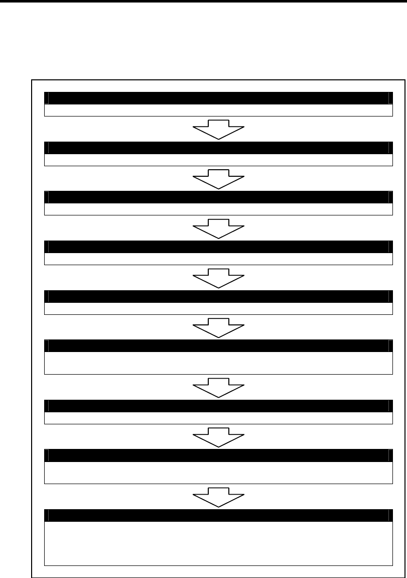
3-2 Setting Up Your Server
SETUP FLOW
Follow the flowchart below to set up the server.
Unpacking the system
Unpack the server and accessories from the shipping carton box.
Installing optional devices
If you have purchased any optional device for the server, see Chapter 9 to install it.
Selecting the server site
Select a suitable site for the server.
Connecting peripheral devices
Connect peripheral devices to the server.
Connecting the power cord
Connect the power cord to the server.
Turning on the server
Power on the server to start software setups. Setups depend on the optional internal
devices installed and the peripheral devices connected.
Installing the operating system
Install an operating system to the server. See Chapter 5.
Installing the utilities
Install the utilities in the provided NEC EXPRESSBUILDER DVD.
See Chapter 6.
Making backup copies of system information
After all the system setup procedures are completed, make backup copies of system
information.
System information is required for recovering the server from the trouble or after
replacing the system board.

Setting Up Your Server 3-3
UNPACKING THE SYSTEM
When you receive your system, inspect the shipping containers prior to unpacking. If the shipping
boxes are damaged, note the damage, and if possible, photograph it for reference. After removing
the contents of the containers, keep the cartons and the packing materials. If the contents appear
damaged when you unpack the boxes, file a damage claim with the carrier immediately.
INSTALLING OPTIONAL DEVICES
To install any optional device, see Chapter 9, "Upgrading Your Server," for the installation
procedure. Proceed to the next section if you have no optional devices to install.
IMPORTANT: There are third-party products (memory modules, hard
disk drives, etc.) available for the server in the markets. However, NEC
recommends that you should use NEC products for stable operation.
NEC assumes no liability for data errors and failures due to malfunction
of the server resulted from installation of those third-party products.
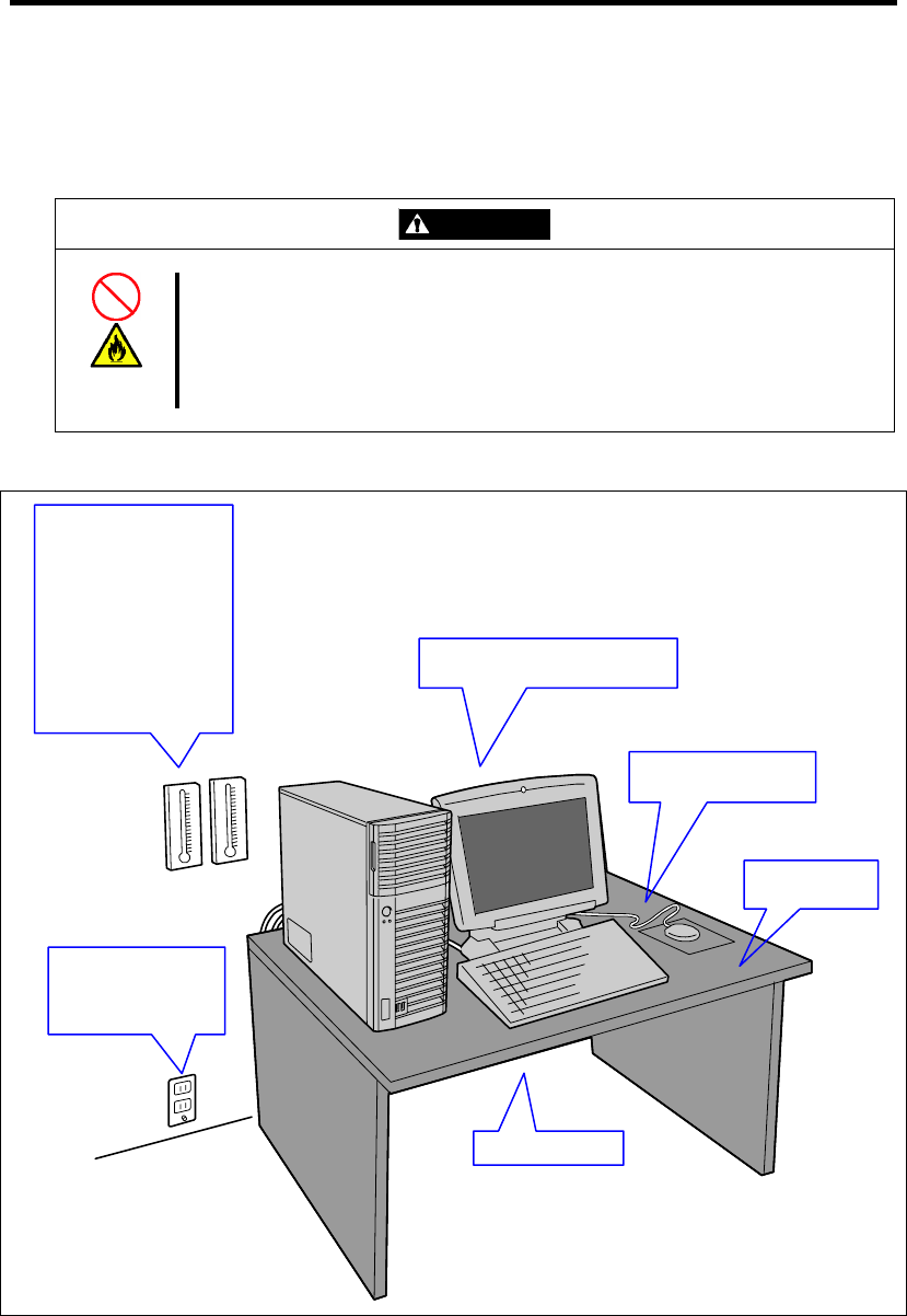
3-4 Setting Up Your Server
SELECTING SERVER SITE
Read the following precautions before selecting a suitable site for your server. The following
describes installation of the server and connections to the server.
CAUTION
Observe the following instructions to use the server safely. Failure to follow
these instructions may cause a fire, personal injury, or property damage. See
pages 1-3 to 1-8 for details.
Never attempt to lift the server only by yourself.
Do not install the server in any place other than specified.
The following figure illustrates a site suitable for installing the server.
* It is recommended that the server should be used in a room where
temperature is in the range between 15 to 25ºC.
Clean and tidy room
Allow clearance of at least 150 mm in
front of and behind the server.
100 to 120 Vac/200 to 240
Vac parallel bi-polar wall
power outlet with the
ground line.
Close enough to connect the
mouse and the display.
Install the server on
a flat, ri
g
id desk
Room that satisfies the following
conditions: *
<While operating>
Temperature: 10 to 35ºC
Humidity: 20 to 80%
Temperature gradient: ±10ºC/h
Atmosphere: 749 to 1040 hpa
<While halting>
Temperature: –10 to 55ºC
Humidity: 10 to 80%
Temperature gradient: ±15ºC/h
Atmosphere: 749 to 1040 hpa

Setting Up Your Server 3-5
When you have selected a server site, hold the server by its bottom with at least three persons and
carry it to the site, then place it slowly and gently.
IMPORTANT: Do not hold the server by its front bezel to lift the
server. The front bezel may be disengaged and damage the server.
Do not install the server in the following locations as it may cause malfunctions of the server.
Places with drastic changes in temperature (e.g., near a heater, air conditioner, or
refrigerator)
Places with strong vibration
Places with corrosive gas in presence, near chemicals, or with possibilities of chemicals
sprayed over
On a non-antistatic carpet
Places with possibilities of falling objects
Places where a power outlet that shares the ground line with another (especially the one to
which a device with large power consumption is connected) must be used for the server
Do not install the server near equipment that generates power noise (e.g., contact spark at
power-on/power-off of commercial power supply through a relay). (To install the server
near equipment that generates power noise, ask your service representative for separating
the power wiring or installing a noise filter.)
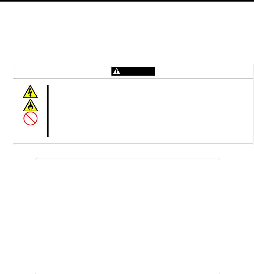
3-6 Setting Up Your Server
CONNECTING PERIPHERAL DEVICES
Connect peripheral devices to the server. The server is provided with connectors for wide variety of
peripheral devices. The figure on the next page illustrates available peripheral devices for the server
in the standard configuration and locations of the connectors for the devices.
CAUTION
Observe the following instructions to use the server safely. Failure to follow
these instructions may cause a fire, personal injury, or property damage. See
pages 1-3 to 1-8 for details.
Do not use any damaged cable connector.
Do not use any unauthorized interface cable.
Do not use the server with any loose interface connection.
Do not step on the interface cable or place any heavy object on it.
IMPORTANT:
Power off the server and a peripheral device before connection.
Connecting a powered peripheral device to the powered server will
cause malfunctions and failures.
To connect a third-party peripheral device or interface cable to the
server, consult with your service representative for availability of
such a device or cable. Some third-party devices may not be used
for the server.
To connect the provided keyboard and mouse, plug their connectors
to the server with the "Δ" mark on the connectors facing right.
Do not connect the serial ports with the telephone line directly.
Do not connect any devices to the connectors not instructed in this
subsection. Doing so could damage the device, your server, or both.
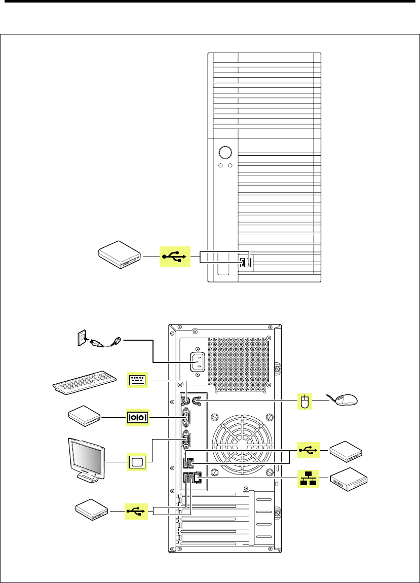
Setting Up Your Server 3-7
Device with the USB interface
(e.g., terminal adapter)
FRONT
Finally, connect the power
cord to the receptacle.
Keyboard
Device with the USB interface
(e.g., terminal adapter)
Mouse
Device with the USB interface
(e.g., terminal adapter)
Device with the serial interface
(e.g., modem)
Display unit
Hub/Switching hub
REAR
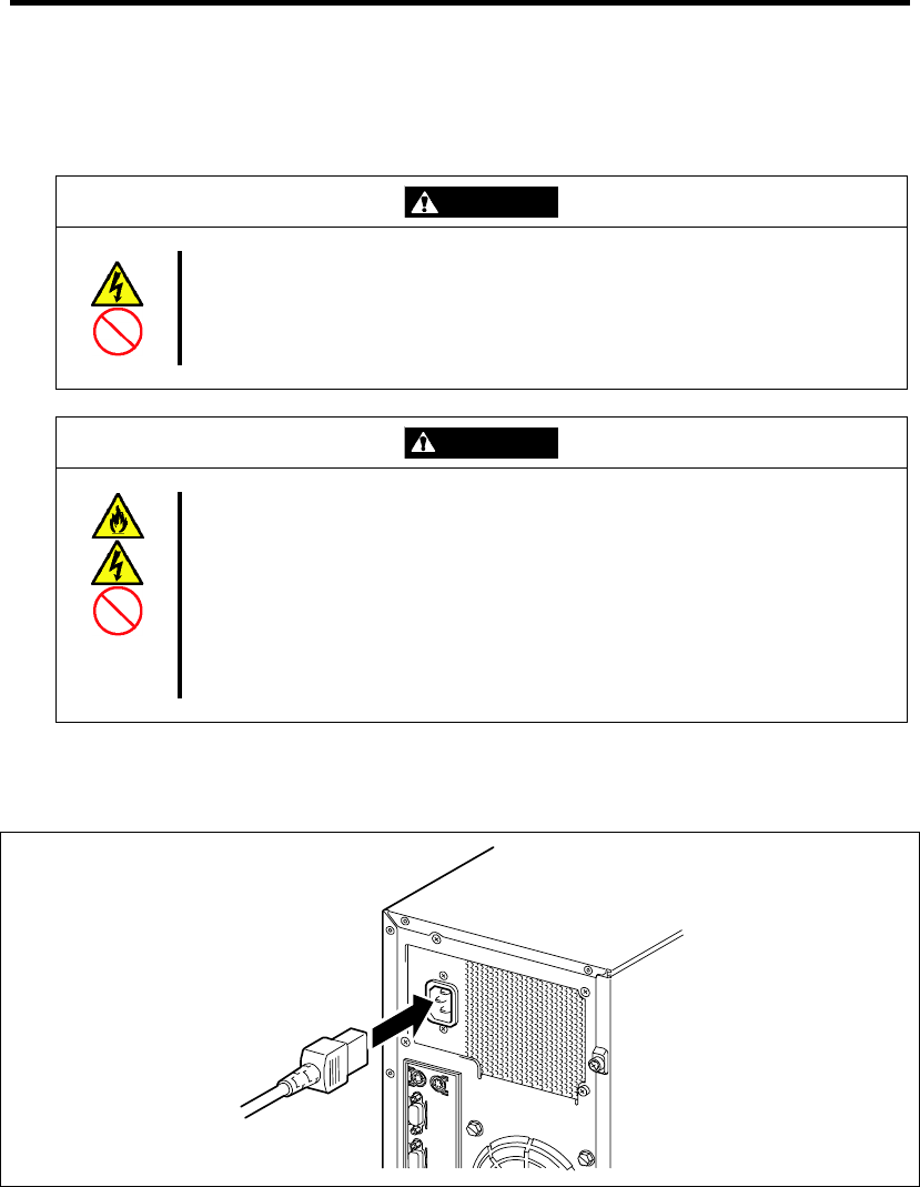
3-8 Setting Up Your Server
CONNECTING POWER CORD
Connect the provided power cord to the server.
WARNING
Observe the following instructions to use the server safely. Failure to follow
these instructions may result in death or serious personal injury. See pages 1-3
to 1-8 for details.
Do not hold the power plug with a wet hand.
CAUTION
Observe the following instructions to use the server safely. Failure to follow
these instructions may cause a fire, personal injury, or property damage. See
pages 1-3 to 1-8 for details.
Do not plug the power cord in to an improper power source.
Do not connect the power cord to an outlet that has an illegal number of
connections.
Insert the power plug into the outlet as far as it goes.
Use the authorized power cord only.
1. Plug the provided power cord into the power receptacle on the rear of the server.
2. Plug the other end of the power cord into the wall outlet.

Setting Up Your Server 3-9
NOTES:
To connect the power cord from the server to an uninterruptive
power supply (UPS), use service outlets on the rear of the UPS.
Refer to the manual that comes with the UPS for details.
When the power cord from the server is connected to a UPS, change
the BIOS SETUP utility of the server to link with power supply
from the UPS.
Change a parameter for "AC-LINK" of the Server menu of the
BIOS SETUP utility. See Chapter 4 for details.
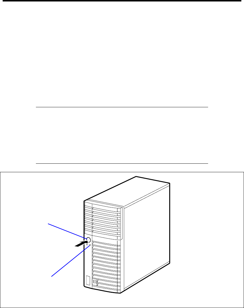
3-10 Setting Up Your Server
TURNING ON THE SERVER
Turn on the server and follow the on-screen instructions for setup.
1. Make sure all external devices, such as a video display, keyboard, and mouse have been
connected, and the power cords are connected.
2. Power on the video display and any other external devices.
3. Make sure that the floppy disk drive contains no floppy disk and the optical disk drive
contains no bootable DVD/CD-ROM.
4. Press the POWER/SLEEP switch.
NOTES:
If the power cord is connected to the power control unit such as the
UPS, turn on the power control unit.
Connect the power cord and wait a few seconds before pressing the
POWER/SLEEP switch. The POWER/SLEEP switch does not work
in a few seconds after connecting the power cord due to firmware
start-up.
POWER/SLEEP lamp
POWER/SLEEP switch

Setting Up Your Server 3-11
The POWER/SLEEP lamp on the front of the server comes on.
In a few seconds, the NEC logo appears on the screen and the Power On Self-Test (POST) begins.
The POST runs automatically when you power on the server or reset it with a keyboard operation
(Ctrl + Alt + Delete). The POST runs diagnostics, initializes the server, sets interrupt vectors,
detects installed peripheral devices, and boots the operating system (if installed). See Chapter 2 for
detailed description on POST.
If the server halts before completing the POST, the POST emits a beep code indicating a fatal
system error requiring immediate attention. (See Chapter 8, "Troubleshooting," for troubleshooting
information.)
During memory test, the POST displays the amount of memory it was able to access and test.
Depending on the amount of installed memory, it may take several minutes to complete the memory
test.
NOTE: The factory-set is defined to hide the POST screen with the
NEC logo screen. You can always change the NEC logo screen to the
POST screen by pressing Esc. To change the start-up screen, use the
BIOS SETUP utility. (See Chapter 4 for details.)
During the POST, you will see the banner message to prompt you to launch the BIOS SETUP utility
stored in ROM on the mother board or on an installed option board.
Start the BIOS SETUP utility appropriate to your system environment to change the CMOS Setup.
For detail explanation on the BIOS SETUP utility for the server, see Chapter 4. For the BIOS utility
for the option board, refer to the manual that comes with the option board.
IMPORTANT: Always allow POST to complete before turning off
your system.

3-12 Setting Up Your Server
INSTALLING OPERATING SYSTEM
See Chapter 5 for installing Microsoft Windows Server 2008 and Microsoft Windows Server 2003.
To install the other operating system listed above, contact your service representative.
IMPORTANT: Use NEC EXPRESSBUILDER for initial setup of
your server. The NEC EXPRESSBUILDER is support software for the
server. It simplifies the process of installing and configuring your server.
See Chapter 6 for details on NEC EXPRESSBUILDER.
INSTALLING UTILITIES
Install the utilities that come with the server. See Chapter 6 for details.
MAKING BACKUP COPIES OF SYSTEM INFORMATION
The system information includes the current BIOS settings and any specific information for the
server.
Save the information after completing the system setup.
Without the backup data, you will not be able to recover the information.
You can save the information by the following process.
1. Connect Flash FDD or USB FDD to the USB connector.
2. Insert the NEC EXPRESSBUILDER DVD into the optical disk drive and reboot the
system.
3. Select [Tool menu (Normal mode)].
4. Select [English].
5. Select [Maintenance Utility].
6. Select [System Information Management].
7. Select [Save].

Chapter 4
Configuring Your Server
Configuration and setup utilities are used to change your system configuration. You can configure
your system, as well as option boards you may add to your system, using the BIOS SETUP Utility.
Several unique system parameters are configured using the BIOS SETUP, which is stored in the
system FLASH memory.
The RAID configuration utility configures the RAID System and logical drives connected to the
Onboard RAID Controller or optional RAID Controller.
If your system has been factory configured, the BIOS SETUP or RAID configuration utility do not
need to be run unless you want to change the password or security features, add certain types of
option boards or devices, upgrade your system board, or change the RAID configuration.
This chapter also provides information on several system configuration parameters that are set by
jumpers on the system board. However, these parameters do not usually require change.

4-2 Configuring Your Server
SYSTEM BIOS (BIOS SETUP UTILITY)
The BIOS Setup utility is provided to make basic hardware configuration for the server. This utility
is pre-installed in the flash memory of the server and ready to run.
The server is configured with the correct parameters using the BIOS Setup utility and shipped in the
best conditions. Thus, you don't need to use the BIOS Setup utility in most cases. However, you
might wish to use the BIOS Setup utility in the cases described below.
IMPORTANT:
The BIOS Setup utility is intended for system administrator use
only.
The BIOS Setup utility allows you to set a password. The server is
provided with two levels of password: Supervisor and User. With
the Supervisor password, you can view and change all system
parameters of the BIOS Setup utility. With the User password,
system parameters available for viewing and changing are limited.
Do not set any password before installing the OS.
The server contains the latest version of the BIOS Setup utility.
Dialog boxes appear on your BIOS Setup utility, thus, may differ
from descriptions in this manual. If you find anything unclear, see
the online help or ask your service representative.
Configuring Your Server 4-3
Starting SETUP Utility
When you turn on the server, the NEC logo appears first. (The POST (Power On Self-Test) screen
might appear first, depending on the SETUP settings.)
The following message then appears at bottom left of the screen.
Message displayed when the NEC logo appears:
Press <F2> to enter SETUP or Press <F12> to Network
Message displayed when the POST screen appears:
Press <F2> to enter SETUP <F10> Boot menu <F12> to boot from
Network
If you press F2 while the above message is displayed, the SETUP utility will launch and its main
menu will be displayed.
If you have previously set a password with the BIOS Setup utility, the password entry screen
appears. Enter the password.
Enter password:[ ]
Up to three password entries will be accepted. If you fail to enter the password correctly for three
consecutive times, the server halts. (You can no longer proceed.) Power off the server.
NOTE: The server is provided with two levels of password:
Administrator and User. With the Administrator password, you can
view and change all system parameters. With the User password,
system parameters available for viewing and changing are limited.
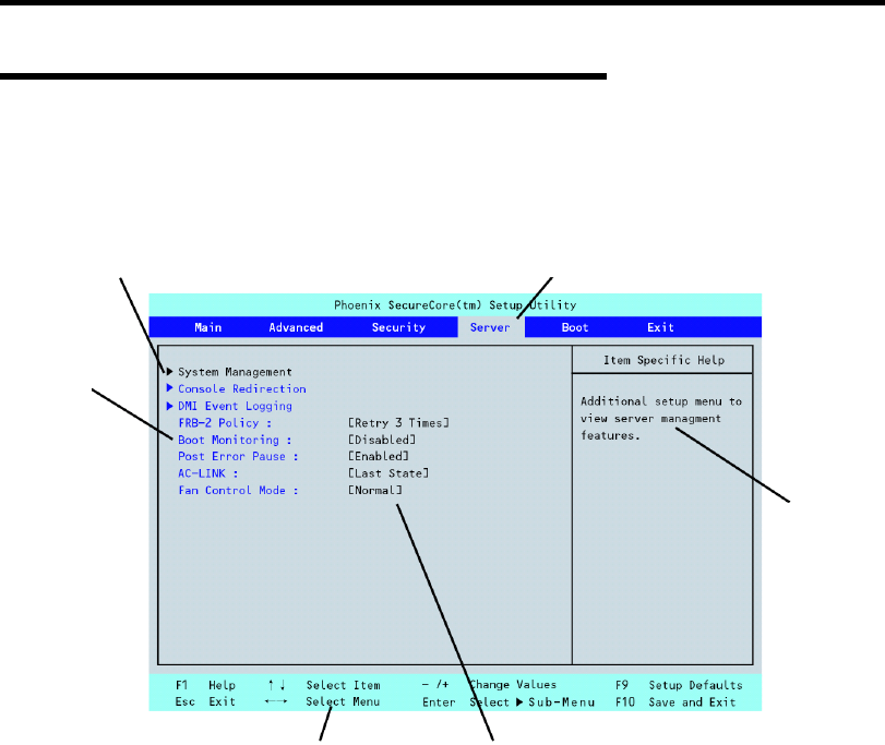
4-4 Configuring Your Server
Description on On-Screen Items and Key Usage
Use the following keyboard keys to work with the BIOS Setup utility. These keys are also listed at
the bottom of the menu screen.
Cursor (↑, ↓): Move cursor up and down. The cursor moves only to the settings
that you can change.
Cursor (←, →): Move between menus.
– and +: Select the previous value (–) or the next value (+) for the field.
Enter Execute command or select Æ submenu.
Esc Exit the current menu and return to the previous menu.
F1: Get Help about an item.
F9: Load default configuration values for this menu.
F10: Save configuration values and exit.
Indicates the current menu.
Indicates there
are submenus.
Setup
item
menu
Explanation of key functions menu Parameter (high-lights upon selection) menu
Online
help
window

Configuring Your Server 4-5
Configuration Examples
The following describes examples of configuration required to use software-link features or for
system operations.
Time and Date Settings
You can also change the time and date settings via the operating system commands.
Select [Main] - [System Time].
Select [Main] - [System Date].
Link with Management Software
To control power supply of the server with NEC ESMPRO Manager via the network
Select [Advanced] - [Advanced Chipset Control] - [Wake On LAN/PME] - [Enabled].
Select [Server] - [AC LINK] - [Stay Off].
Hard Disk Drive
To check the hard disk drive status
Select [Main] - [SATA Port 0/1/2/3/4/5] and check the status indications.
UPS
To link power supply with the UPS
To power on the server when power is supply from the UPS
Select [Server] - [AC LINK] - [Power On].
To keep the server off-powered even when power is supplied from the UPS
Select [Server] - [AC LINK] - [Stay Off].
Boot
To check the boot order
Select [Boot] and check the current boot order.
To change the boot order of devices connected to the server
Select [Boot] and specify the boot order.
IMPORTANT: If you have installed any bootable device, be sure to
run BIOS Setup menu to check the boot priority on [Boot] menu. If the
bootable device is displayed in "Excluded from boot order", put the
cursor onto the device, then press x to move it to "Boot priority order".
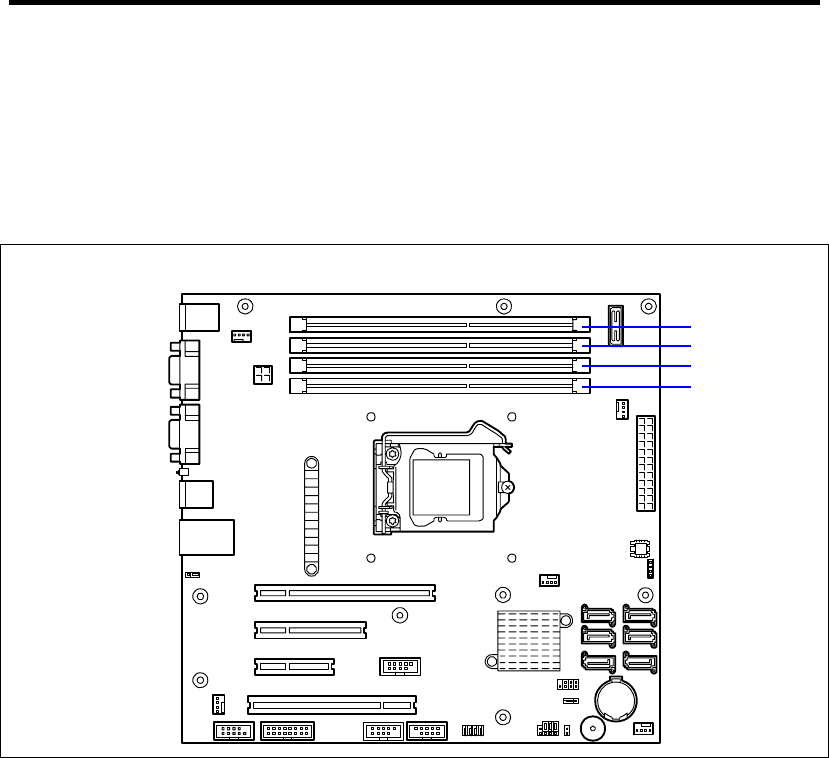
4-6 Configuring Your Server
Memory
To check the installed memory (DIMM board) status
Select [Advanced] - [Memory Configuration] and check the status indications.
The on-screen DIMM group numbers and socket locations on the mother board are
associated as shown in the following figure.
To clear the memory (DIMM board) error information
Select [Advanced] - [Memory Configuration] - [Memory Retest] - [Yes] and reboot.
To run power-on memory test
Select [Advanced] - [Memory Configuration] - [Extended RAM Step] - [1MB] and
reboot.
CPU
To check the installed CPU status
Select [Main] - [Processor Settings] – [Processor CPUID] and check the status
indications.
DIMM #2
DIMM #4
DIMM #1
DIMM #3

Configuring Your Server 4-7
Keyboard
To set Numlock
Select [Advanced] - [Numlock] – [On]/[Off].
Security
To set passwords on the BIOS
Select [Security] - [Set Supervisor Password] and enter a password.
Select [Security] - [Set User Password] and enter a password.
Set Supervisor password first, then User password.
External Devices
To set up external devices
Select [Advanced] - [Peripheral Configuration] and set up each device.
Internal Devices
To install the RAID Controller card or SCSI controller card
Select [Advanced] - [PCI Configuration] - [PCI Slot n Option ROM] - [Enabled].
n: slot number
To clear the hardware configuration data (after installing/removing internal devices)
Select [Advanced] - [Reset Configuration Data] - [Yes] and reboot.
Running the Server with the Fan Low-speed (Silent) Mode)
To run the server with the fan set to low-speed (silent) mode
Select [Server] - [Fan Control Mode] - [Low].
If a board is inserted in the server’s PCI slot, the fan cannot be set to low-speed (silent)
mode.
Saving the Configuration Data
To save the current configuration data and exit from SETUP
Select [Exit] - [Exit Saving Changes].
To discard changes to the current configuration data and exit from SETUP
Select [Exit] - [Exit Discarding Changes].
To load the default setup
Select [Exit] - [Load Setup Defaults].
To discard changes to the current configuration data
Select [Exit] - [Discard Changes].

4-8 Configuring Your Server
To save the current configuration data
Select [Exit] - [Save Changes].

Configuring Your Server 4-9
Menu and Parameter Descriptions
The SETUP utility has the following six major menus:
Main
Advanced
Security
Server
Boot
Exit
To set minute functions, select a submenu from the above menus. The following describes available
functions and parameters, as well as the factory-set, for each menu.

4-10 Configuring Your Server
Main
Option Parameter Description Your Setting
System Time HH:MM:SS Set the system time.
System Date MM/DD/YYYY Set the system date.
Hard Disk Pre-Delay [Disabled]
3 seconds
6 seconds
9 seconds
12 seconds
15 seconds
21 seconds
30 seconds
When accessing the IDE device
for the first time during POST,
the system waits for the
specified time until the device
becomes ready.
SATA Port 0
SATA Port 1
SATA Port 2
SATA Port 3
SATA Port 4
SATA Port 5
– Shows the information on the
device connected to each
channel on the submenu. The
settings of some items may be
changed. However, leave the
items as they are at the
shipment.
Processor Settings – Shows the processor settings
submenu.
Language [English (US)]
Français
Deutsch
Español
Italiano
Select which language BIOS
displays.
[ ]: Factory-set
IMPORTANT: Check and adjust the system clock before the
operation if any of the following conditions is applicable.
After carriage of device
After storage of device
After the device is entered into the pause state under the
environmental condition enduring device operation (temperature:
10°C - 35°C, humidity: 20% - 80%)
Check the system clock at the rough rate of once per month. When the
system clock is installed in a system requiring high time precision, it is
recommended to use a time server (NTP server).
If the system clock is remarkably delayed or advanced as the passage of
time in spite of adjustment, contact your service representative for
maintenance.

Configuring Your Server 4-11
Processor Settings
Option Parameter Description Your Setting
CPU Speed – Displays clock speed for the
processor. (View only)
Processor CPUID Numeral (xxxx) Displays the processor ID.
(View only)
Processor L2 Cache – Displays L2 cache size for
processor.
Processor L3 Cache – Displays L3 cache size for
processor.
Active Processor Cores [ALL]
1
2
Specifies the number of valid cores
in the processor.
Execute Disable Bit [Enabled]
Disabled
Enables or disables the Execute
Disable Bit feature.
Displayed only when the CPU
supports Execute Disable Bit.
Intel SpeedStep(R)
Technology
[Enabled]
Disabled
Enables or disables the Intel(R)
SpeedStep feature.
Fixed to "Disabled" if the processor
does not support this feature.
Turbo Boost
Technology
[Enabled]
Disabled
Enables or disables the Intel(R)
Turbo Boost Technology. Displayed
only when the CPU supports this
feature.
C1 Enhanced Mode [Enabled]
Disabled
Enables or disables the C1
Enhanced Mode.
Processor C3 Report Disabled
ACPI C2
[ACPI C3]
Specifies the ACPI state to which
the C3 state of the processor is
mapped.
Virtualization
Technology
[Enabled]
Disabled
Enables or disables the Intel(R)
virtualization technology.
[ ]: Factory-set

4-12 Configuring Your Server
Advanced
Option Parameter Description Your Setting
Boot-time Diagnostic
Screen
Enabled
[Disabled]
When enabled, the BIOS will display
the POST progress.
When disabled, the BIOS will
display the NEC logo during POST.
Cannot be disabled during console
redirection.
Reset Configuration Data [No]
Yes
Select "Yes" if you want to clear the
system configuration data during the
next boot. Automatically reset to
"No" in the next boot.
NumLock On
[Off]
Enables or disables Numlock
feature at system startup.
Memory Error [Boot]
Halt
This option is used to specify
whether the system stops at the end
of POST when a memory error has
been detected during POST.
This option is enabled when [POST
Error Pause] on the [Server] menu
is set to [Enabled]. If there is no
usable memory in the system, the
system will stop at the end of POST
even if [Boot] is specified for this
option.
[ ]: Factory-set
IMPORTANT: Be sure to take a note of boot priority before selecting
"Yes" for [Reset Configuration Data], because the information on boot
device will be cleared. Select [Exit Saving Changes] to restart the
system, run BIOS SETUP utility, and provide settings for boot device
order again.

Configuring Your Server 4-13
Memory Configuration
Option Parameter Description Your Setting
Installed memory – Indicates the total capacity of the base
memory. (View only)
Available under
4GB
– Indicates the capacity of memory
available in the area under 4GB. (View
only)
DIMM1-4 Status Normal
Disabled
Not installed
Error
Indicates the current memory status.
"Normal" indicates the normal status,
"Disabled" indicates a memory error, "Not
installed" indicates no DIMM installed,
and
"Error" indicates the system is forcibly
started with memory error. (View only).
Memory Retest Yes
[No]
Causes BIOS to retest all memory on the
next boot. Automatically reset to "No" at
the next boot.
Extended RAM
Step
1MB
[Disabled]
"1MB" indicates that the memory test is
done in the unit of 1MB.
"Disabled" indicates that only memory
initialization is done.
Only pressing Space is acceptable to
suspend the test during the memory test.
[ ]: Factory-set
PCI Configuration
Option Parameter Description Your Setting
PCI Slot 1-4
Option ROM
[Enabled]
Disabled
Displays the submenu to specify whether to
enable or disable the BIOS on the device
(board) connected to PCI slot.
Set this item to "Enabled" when the RAID
Controller or SCSI controller is connected
with the hard disk drive which contains an
OS.
Set this item to "Disabled" when the LAN
controller which contains ROM BIOS is
used but the board does not provide
network booting.
Disabling Option ROM Scan saves memory
consumption and time for startup.
[ ]: Factory-set
IMPORTANT: If the RAID Controller, LAN board (network boot), or
SCSI controller is connected with the hard disk drive that does not
contain an OS, set the parameter for "PCI Slot x Option ROM" (x: slot
containing the PCI card) to "Disabled".

4-14 Configuring Your Server
PCI Device, Onboard VGA
Option Parameter Description Your Setting
Onboard VGA
Option ROM Scan
[Auto]
Force
Selects whether the option ROM of
onboard video controller is executed
automatically for forcedly.
When [Auto] is selected, the ROM of the
VGA card is preferentially scanned.
[ ]: Factory-set
PCI Device, Onboard Lan
Option Parameter Description Your Setting
LAN Controller Disabled
[Enabled]
Enables or disables onboard LAN
controller.
LAN Option ROM
Scan
Disabled
[Enabled]
Enables or disables an option ROM of
onboard LAN controller.
[ ]: Factory-set
Peripheral Configuration
IMPORTANT: Note that the interrupt and/or base I/O address are not
overlapped with others.
Option Parameter Description Your Setting
Serial Port A Disabled
[Enabled]
Selects whether serial port A is enabled or
disabled.
Base I/O
address
[3F8h]
2F8h
3E8h
2E8h
Selects the base I/O address for serial port
A.
Interrupt IRQ 3
[IRQ 4]
Selects the interrupt for a serial port A.
Serial Port B Disabled
[Enabled]
Selects whether serial port B is enabled or
disabled.
Base I/O
address
3F8h
[2F8h]
3E8h
2E8h
Selects the base I/O address for serial port
B.
Interrupt [IRQ 3]
IRQ 4
Selects the interrupt for a serial port B.
SATA RAID
Enable
[Disabled]
Enabled
Indicates whether the RAID disk drives that
uses the onboard SATA is enabled or
disabled. (View only)
To enable or disable the RAID system, use
the jumper switch on mother board.
[ ]: Factory-set

Configuring Your Server 4-15
Advanced Chipset Control
Option Parameter Description Your Setting
Multimedia Timer Disabled
[Enabled]
Specify whether the system supports
the multimedia timer feature.
Intel(R) VT-d Disabled
[Enabled]
Specify whether the Intel(R)
Virtualization Technology for Directed
I/O feature is enabled or disabled.
This item appears only when the
processor supports this feature.
Wake On
LAN/PME
Disabled
[Enabled]
Specify whether the remote power-on
function through a network is enabled
or disabled.
Wake On Ring [Disabled]
Enabled
Specify whether the remote power-on
function through a serial port (modem)
is enabled or disabled.
Wake On RTC
Alarm
[Disabled]
Enabled
Specify whether the remote power-on
function that uses the RTC alarm
feature is enabled or disabled.
Set this option to [Enabled] to shift
from standby mode to sleep mode
after a specified time has elapsed by
using the OS power control function.
[ ]: Factory-set
IMPORTANT: If the AC power is turned off while the Wake On Ring
feature is enabled, this feature is disabled at the next system boot after
AC power-on. You need to press the Power switch to boot the system. If
the AC power is turned off, Wake On Ring feature on power
management chip is disabled until the next DC power-on.

4-16 Configuring Your Server
Security
Press Enter on "Set Supervisor Password" or "Set User Password," to display the password entry
screen.
Enter the passwords on the dialog box.
IMPORTANT:
User password can be set only when Supervisor password is already
set.
Set the passwords only after OS is installed.
If you forget the passwords, contact your service representative.
Option Parameter Description Your Setting
User
Password Is
Clear
Set
Indicates the user password setting
status.
Supervisor
Password Is
Clear
Set
Indicates the supervisor password
setting status.
Set Supervisor
Password
Up to eight
alphanumerics
Press Enter to display the
supervisor password entry screen.
This password enables all the
SETUP menus to be accessed. This
setting can be done only on login
with the password input of
"Supervisor" at start of SETUP.
Set User
Password
Up to eight
alphanumerics
Press Enter to display the user
password entry screen. For this
password, accessing to the SETUP
menu is restricted.
This setting can be done only on
login with the password input of
"Supervisor" at start of SETUP.
Password on
boot
[Disabled]
Enabled
Specify whether the passwords are
entered or not on booting. At first,
the supervisor password must be
set. If the supervisor password is set
and this option is disabled, BIOS
determines that a user is booting.
Fixed disk boot
sector
[Normal]
Write Protect
Specify whether to permit writing
into boot sector of the IDE hard disk
drive or not. The server does not
support IDE hard disk drive.
Disable USB
Port
[Disabled]
Front
Rear
Internal
Front + Rear
Front + Internal
Rear + Internal
Front + Rear + Internal
Select the USB port to be disabled
or enabled.
[ ]: Factory-set

Configuring Your Server 4-17
Server
Option Parameter Description Your Setting
FRB-2 Policy Disable FRB2 Timer
[Retry 3 Times]
Always Reset
Specify the operation of the processor
when FRB level 2 error occurred in
BSP.
Boot Monitoring [Disabled]
5 Minutes
10 minutes
15 minutes
20 minutes
25 minutes
30 minutes
35 minutes
40 minutes
45 minutes
50 minutes
55 minutes
60 minutes
Specify whether to enable or disable
the boot monitoring function on
booting, or select the time limit for
timeout.
Boot Monitoring
Policy
[Retry 3 Times]
Always Reset
Specify the processing at the
occurrence of timeout during boot
monitoring.
If [Retry 3 times] is selected, the
system is reset after the occurrence of
timeout and OS boot is retried up to
three times.
If [Always Reset] is selected, the
system is reset after the occurrence of
timeout and OS boot is retried
repeatedly.
Post Error
Pause
Disabled
[Enabled]
Specify whether to stop the POST
once at the end of POST if an error
occurs during the POST.
AC-LINK Stay Off
[Last State]
Power On
Specify the state of power when the
AC power to the server is turn off
once and then on.
Fan control
Mode
[Normal]
Low
If the silent mode available on the
system, specifying [Low] lets the
system enter into the silent mode
where rotation of fans are controlled.
[ ]: Factory-set

4-18 Configuring Your Server
The table below shows the operation when the AC power to the server is turn off once and then on
again, depending on the setting of "AC LINK."
Setting of AC LINK
System status before AC power off Stay Off Last State Power On
Operating Off On On
Aborting (DC power being off also) Off Off On
Forced shutdown Off Off Off
* Press the POWER/SLEEP switch continuously for four seconds or longer. This forcibly
turns off the power. After this operation, the system does not turn on the power even
though the AC-LINK setting is set to Power On.
IMPORTANT:
To power on the server from the UPS (Uninterruptible Power
Supply), select [Server] - [AC Link] - [Power On].
If the server is connected to the UPS, set at least 10 seconds delay in
the power-on schedule.

Configuring Your Server 4-19
System Management
Option Parameter Description Your Setting
BIOS Version – Displays the current BIOS version.
(View only)
Board Part Number – Displays the part number of mother
board. (View only)
Board Serial Number – Displays the serial number of mother
board. (View only)
System Part Number – Displays the part number of the
system. (View only)
System Serial Number – Displays the serial number of the
system. (View only)
Chassis Part Number – Displays the part number of the
chassis. (View only)
Chassis Serial Number – Displays the serial number of the
chassis. (View only)
Onboard LAN MAC
Address
– Displays the MAC address of the
onboard LAN port 1. (View only)
GBIA Module Version – Displays the current GBIA version.
(View only)
[ ]: Factory-set

4-20 Configuring Your Server
Console Redirection
Option Parameter Description Your Setting
Console
Redirection
[Disabled]
Serial Port A
Serial Port B
Specify the address/interrupt of the
serial port to which a remote console
is connected.
Baud Rate 9600
[19.2K]
38.4K
57.6K
115.2K
Specify the baud rate used for the
interface with the remote console
connected.
Flow Control None
Xon/Xoff
[CTS/RTS]
Specify the flow control method.
Terminal Type PC ANSI
[VT100+]
VT-UTF8
Specify the type of remote console.
Continue
Redirection after
POST
Disabled
[Enabled]
Specify whether to continue console
redirection feature after completion of
POST.
Remote Console
Reset
[Disabled]
Enabled
Specify whether to enable or disable
resetting by Escape command (Esc
R) sent from the remote console.
If the server is connected with the
management PC that uses NEC
ESMPRO Manager, this option is
always enabled even if "Disabled" is
specified here.
[ ]: Factory-set
DMI Event Logging
Option Parameter Description Your Setting
Event log validity – Displays the status of event logs
stored in the system.
Event log
capability
– Displays the free space for storing
event logs.
View DMI event
log
– Press Enter to display the event logs
stored in the system. See Chapter 8
“Troubleshooting” for the meanings of
the event logs and the recommended
action to take.
Event logging [Enabled]
Disabled
Specify whether to store the event log
or not.
Clear all DMI
event logs
[No]
Yes
When set to [Yes] and reboot the
system, the stored event logs are
cleared.
[ ]: Factory-set

Configuring Your Server 4-21
Boot
If you move the cursor to the position of "Boot," the Boot menu appears, which is used to set the
boot priority.
Indication Device
USB CDROM USB CD-ROM drive
IDE CD ATAPI CD-ROM
USB FDC Flash FDD or USB FDD
USB KEY USB flash memory device
IDE HDD IDE hard disk drives
PCI SCSI Internal hard disk drives installed in your system ("Software RAID" is
displayed in the RAID configuration.)
USB HDD USB hard disk drive
PCI BEV IBA GE Slot xxxx: Onboard LAN
Other indication: Optional PCI board.
1. When BIOS detects a bootable device, it displays the information on the device in the
relevant indication.
To boot the server from a desired device, the device must be registered as a boot device.
(Up to eight boot devices can be registered.)
2. Pressing X after selecting a device allows the selected device to be registered as a boot
device or deleted from the registration.
With eight boot devices being registered, any other device cannot be registered as a boot
device even if you press X. To register a device as a boot device newly, first delete the
registration of a device registered as a boot device but not booted any more.
3. You can change the boot priority (first to eighth) of each device by using ↑, ↓, + and/or –.
To change the priority of a device, move the cursor to the device by using the ↑ or ↓, and
press + or –.

4-22 Configuring Your Server
Exit
The options on the menu are described below.
Exit Saving Changes
Exit after writing all modified BIOS SETUP item values to CMOS.
Exit Discarding Changes
Exit leaving CMOS unmodified. User is prompted if any of the setup fields were modified.
Load Setup Defaults
Load default values for all BIOS SETUP items.
Discard Changes
Read the previous values of the all BIOS SETUP items from CMOS.
Save Changes
Write all BIOS SETUP item values to CMOS.

Configuring Your Server 4-23
RAID SYSTEM CONFIGURATION
This section describes how to use the internal hard disk drives as RAID System by Onboard RAID
Controller (LSI Embedded MegaRAID™).
About the optional RAID Controller (N8103-109/116A/117A), refer to the documents provided
with optional RAID Controller.
IMPORTANT: When Onboard RAID Controller (LSI Embedded
MegaRAID™) or Optional RAID Controller (N8103-109/116A/117A)
is used, do not let the system enter hibernation or standby mode.
RAID
Overview of RAID System
What is RAID (Redundant Array of Inexpensive Disks)?
RAID is an abbreviation for "Redundant Array of Inexpensive Disks". The RAID technology allows
more than one hard disk drive (HDD) to be handled collectively.
In actual, RAID can configure more than one HDDs as a single disk array (disk group) to operate
the HDDs effectively. This can bring higher performance than a single HDD of a large capacity.
The Onboard RAID Controller (LSI Embedded MegaRAID™) has a feature to divide a single disk
group into several logical drives (virtual disks). Operating system recognizes these logical drives as
if it were a single hard disk drive. Operating system accesses to more than one hard disk drive
configuring a disk group in parallel.
Some RAID levels can recover data from remaining data and parity by using rebuild feature if an
error occurs in a single HDD. This can provide high reliability for the system.
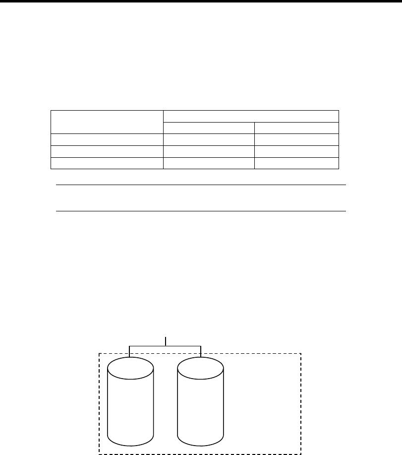
4-24 Configuring Your Server
RAID Levels
The record mode enabling the RAID feature includes several levels. Among the levels, the Onboard
RAID Controller (LSI Embedded MegaRAID™) supports RAID levels 0, 1, and 10. The number of
hard disk drives required to create a disk group varies depending on the RAID level as shown in the
table below.
Number of required HDDs
RAID level Min. Max.
RAID 0 1 4
RAID 1 2 2
RAID 10 4 4
NOTE: For details of the RAID levels, see "RAID Levels" described
later in this chapter.
Disk Group
A disk group is configured with more than one HDDs.
The allowable number of disk groups is equal to the number of HDDs.
The figure below shows a sample configuration. The three HDDs are connected to the Onboard
RAID Controller (LSI Embedded MegaRAID™), creating one disk group (DG).
HDD 1
(80 GB)
HDD 2
(80 GB)
RAID Controller
Disk Group 0: 160 GB
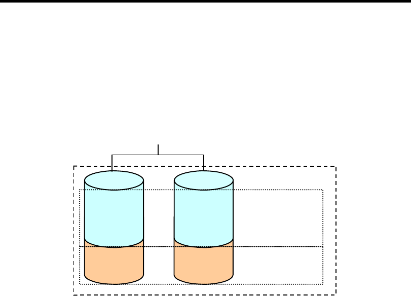
Configuring Your Server 4-25
Virtual Disk
Virtual disk is a logical drive defined in disk group. It is recognized as a physical drive by OS. The
allowable number of virtual disks is up to 8 per disk group, or up to 8 per controller.
The figure below shows a sample configuration in which the Onboard RAID Controller (LSI
Embedded MegaRAID™) is connected with two HDDs, creating one Disk Group. Two RAID1
virtual disks (VD) are defined in the Disk Group.
HDD 1
(80 GB)
HDD 2
(80 GB)
RAID Controller
DG0 160 GB
VD1-2
30GB
VD1-1
30GB
VD0-1
50GB
VD0-2
50GB
VD0 (RAID1)
50 GB
VD1 (RAID1)
30 GB
Hot-Spare
The hot-spare is prepared as an auxiliary HDD substituting for a defected HDD included in a disk
group which is configured at a redundant RAID level. Detecting a HDD fault, the system
disconnects the HDD (or makes it offline) and starts rebuild using the hot-spare.

4-26 Configuring Your Server
RAID Levels
This section describes RAID levels that the Onboard RAID Controller (LSI Embedded
MegaRAID™) supports. The available RAID levels are RAID0, RAID1, and RAID10 (striping of
RAID1).
Characteristics of RAID Levels
The table below lists the characteristics of the RAID levels.
Level Function Redundancy Characteristics
RAID0 Striping No • Data read/write at the highest rate
• Largest capacity
• Capacity: (capacity of single HDD) ×
(number of HDDs)
RAID1 Mirroring Yes • Two HDDs required
• Capacity: capacity of single HDD
RAID10 Striping of RAID1 Yes • Four or more HDDs required
• Capacity: (capacity of single HDD) ×
((number of HDDs) / 2)
RAID0
In RAID0, data to be recorded is distributed to HDDs. The mode is called "striping".
In the figure below, data is recorded in stripe 1 (disk 1), stripe 2 (disk 2), and stripe 3 (disk 3)… in
the order. Because RAID0 allows all HDDs to be accessed collectively, it can provide the best disk
access performance.
IMPORTANT: RAID0 cannot have data redundancy. If a HDD is
defected, the data saved in the HDD cannot be recovered.
RAID Controller
HDD 1 HDD 2
Stripe 1
HDD 3
Stripe 4
Stripe 2
Stripe 5
Stripe 3
Stripe 6
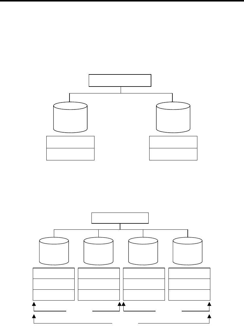
Configuring Your Server 4-27
RAID1
In the RAID1 level, data saved in a HDD is written to another HDD without change. The mode is
called "mirroring".
When data is written onto a single HDD, the same data is written onto another HDD. If either of the
HDDs is defected, the other HDD containing the same data can substitute for the defected HDD.
Thus the system can continue to operate without interruption.
RAID Controller
HDD 1 HDD 2
Stripe 1
Stripe 2
Stripe 1
Stripe 2
RAID10
Data to be recorded is distributed to two HDDs in mirroring mode. Then, each mirrored data is
written onto HDD by striping. Owing to this feature, high disk access performance of RAID0 and,
in addition, high reliability of RAID1 can be achieved.
RAID Controller
HDD 1 HDD 2
Stripe 1
HDD 3
Stripe 3
Stripe 1
Stripe 3
Stripe 2
Stripe 4
Stripe 5 Stripe 5 Stripe 6
HDD 4
Stripe 2
Stripe 4
Stripe 6
RAID1 RAID1
RAID0
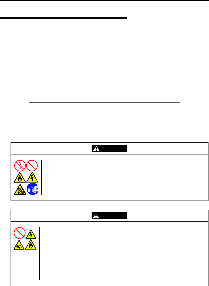
4-28 Configuring Your Server
Configuration by Onboard RAID Controller
This section describes how to use the internal hard disk drives as RAID System by Onboard RAID
Controller (LSI Embedded MegaRAID™).
Installing the Hard Disk Drives
Install the required number of hard disk drives for the desired RAID level to your server. See
Chapter 9 for installation procedure.
IMPORTANT: Use hard disk drives of the same revolution. In
addition, use two hard disk drives of the same capacity if you are going
to configure RAID1.
Enabling RAID Feature
To configure a hard disk drive as RAID System, change the RAID System configuration jumper
switch on mother board.
WARNING
Observe the following instructions to use the server safely. Failure to follow
these instructions may result in death or serious personal injury. See pages
1-3 to 1-8 for details.
Do not disassemble, repair, or alter the server.
Do not remove the lithium battery.
CAUTION
Observe the following instructions to use the server safely. Failure to follow
these instructions may result in death or serious personal injury. See pages 1-3
to 1-8 for details.
Make sure to complete board installation.
Do not install the server on a rack with leaving covers removed.
Do not pinch your finger with mechanical components.
Note high temperature.
Do not pull out a device from the rack if the rack is unstable.
Do not leave more than one device being pulled out from the rack.
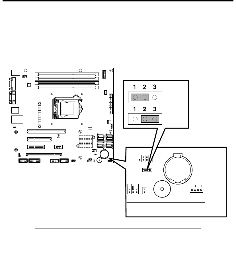
Configuring Your Server 4-29
1. See the section "Preparing for Installation and Removal" as described in Chapter 9 of this
guide to prepare.
2. Remove the side cover (see Chapter 9).
3. Locate the position of the RAID configuration jumper on the mother board as shown
below.
NOTES:
The factory setting of the RAID configuration jumper switch
depends on your order.
If you are using an Optional RAID Controller, set the RAID
configuration jumper switch to the position "non-RAID".
4. Install the side cover removed in Step 2.
Then, configure the RAID system by using the LSI Software RAID Configuration Utility.
non-RAID
RAID
RAID configuration jumper switch
(SWRAID)
Mother board

4-30 Configuring Your Server
Setup Utility
This section describes the RAID configuration tool, LSI Software RAID Configuration Utility.
Running LSI Software RAID Configuration Utility
1. When the following screen appears after you have powered on the server, press Esc.
The POST screen appears.
2. Check the description as shown below on the POST screen, then press Ctrl + M.
LSI Software RAID Configuration Utility starts.
LSI SoftwareRAID BIOS Version xxxxxx
LSI MPT RAID Found at PCI Bus No:xx Bev No:xx
Scanning for port 00 Responding xxxxxxxx xxxxMB
Standard FW xxx DRAM=128MB(SDRAM)
xx Logical drive(s) Configured
Press <Ctrl><M> to Run LSI Software RAID Configuration Utility
NOTE: At least one hard disk drive must be connected to launch the
LSI Software RAID Configuration Utility.
LSI Software RAID Configuration Utility TOP Menu (Management Menu)

Configuring Your Server 4-31
Quitting LSI Software RAID Configuration Utility
To quit the utility, press Esc in the TOP menu of LSI Software RAID Configuration Utility.
When a confirmation message appears, select [Yes].
When the above message appears, press Ctrl + Alt + Delete.
The server is rebooted.

4-32 Configuring Your Server
Menu Tree
+: Selection/execution parameter : Setting parameter. •: Information display
>: Can be set (modified) after creation of virtual drive
Menu Description
+Configure Performs Configuration settings
+Easy Configuration Set configuration (Using fixed value)
+New Configuration Set new configuration
+View/Add Configuration Additional setting / viewing configuration
+Clear Configuration Clear configuration
+Select Boot Drive Chose Bootable Virtual Drive
+Initialize Initialize virtual drive
+Objects Various settings
+Adapter Set RAID Controller
+Sel. Adapter Clear configuration
Rebuild Rate 30
Chk Const Rate 30
FGI Rate 30
BGI Rate 30
Disk WC Off
Read Ahead On
Bios State Enable
Cont on Error Yes
Fast Init Enable
Auto Rebuild On
Auto Resume Enable
Disk Coercion 1GB
Factory Default
+Virtual Drive Virtual drive operation
+Virtual Drives Select virtual drive (when multiple virtual drives exist)
+Initialize Initialize virtual drive
+Check Consistency Check virtual drive redundancy
+View/Update Parameters Display virtual drive information
• RAID Display RAID level
• SIZE Display virtual drive capacity
• Stripe SIZE Display stripe size
• #Stripes Display the number of hard disk drives in virtual drive
• State Display virtual drive status
• Spans
• Disk WC Off: Write through
On: Write back
• Read Ahead
+Physical Drive Physical drive operation
+Physical Drive Selection Menu Select physical drive
+Make HotSpare Set as hot-spare disk for auto rebuilding
+Force Online Make a disk online
+Force Offline Make a disk offline
+Drive Properties Display hard disk drive information
• Device Type Hard disk drive type
• Capacity Hard disk drive capacity
• Product ID Hard disk drive model
• Revision No. Hard disk drive revision
+Rebuild Perform rebuilding
+Check Consistency Perform virtual drive redundancy check

Configuring Your Server 4-33
Operating Procedures for Configuration Utility
Creating/Adding Configuration
Run LSI Software RAID Configuration Utility
Set new configuration information (pack/virtual drive settings)
Check the virtual drive settings
Initialize virtual drive
Perform Consistency Check
Exit LSI Software RAID Configuration Utility
1. Run LSI Software RAID Configuration Utility.
2. Select "Configure" → "New Configuration" from the TOP menu (Management Menu).
Select "View/add Configuration" to add configuration.
IMPORTANT:
Creating a configuration using "New Configuration" menu clears
the existing configuration information. To add configuration
information to the existing configuration, select "View/add
Configuration."
You cannot create Striping of RAID1 or set the virtual drive
capacity on "Easy Configuration" menu.
Use "New Configuration" or "View/Add Configuration" instead.
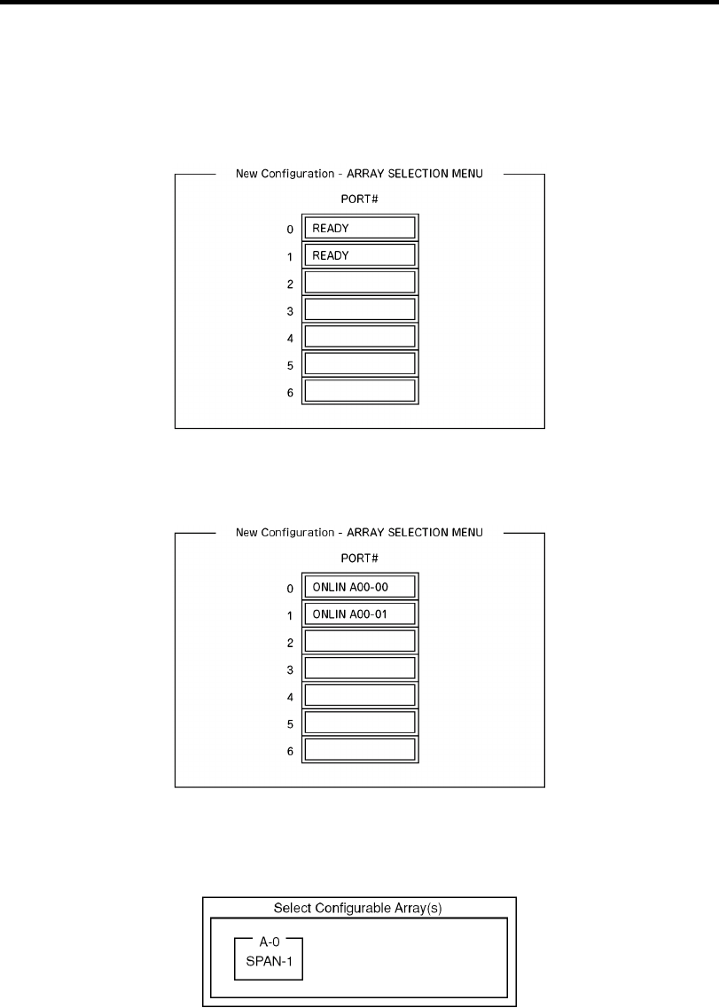
4-34 Configuring Your Server
3. When a confirmation message (Proceed?) is displayed, select "Yes."
The SCAN DEVICE starts (scanning information is displayed at the bottom of the screen).
Upon completion of SCAN DEVICE, the "New Configuration - ARRAY SELECTION
MENU" screen appears.
4. Move the cursor onto the hard disk drive to be packed by using cursor key and then press
Space to select the hard disk drive.
The display for the selected hard disk drive changes from READY to ONLINE.
5. Press F10 to set "Select Configurable Array(s)".
6. Press Space.
SPAN-1 is set.
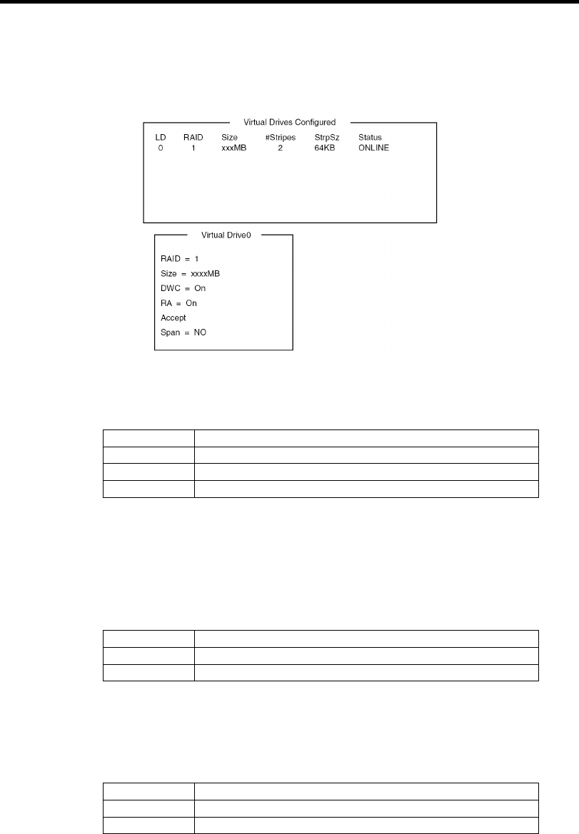
Configuring Your Server 4-35
7. Press F10 to create virtual drive.
The "Virtual Drives Configured" screen appears. (The figure below shows an example of
RAID1 configured with two hard disk drives.)
8. Select "RAID," "Size", "DWC", "RA", or "Span" by using cursor keys. Then press Enter
to fix the selection and set each value.
(1) "RAID": Sets RAID level.
Parameter Remarks
0 RAID0
1 RAID1
10 Striping of RAID1
The selectable RAID level varies depending on the number of hard disk drives
that configure a pack.
(2) "Size": Sets virtual drive size.
Up to 8 virtual drives can be created per RAID Controller.
(3) "DWC": Sets parameter for Disk Write Cache.
Parameter Remarks
Off Write through
On *1 Write back
*1 Recommended setting.
"Write-back On" enables good performance, however, cache data may be lost
at an unexpected power failure. "Write-back Off" reduces performance by
approximately 50%.
(4) "RA": Sets parameter for Read Ahead.
Parameter Remarks
Off Does not perform read ahead.
On Performs read ahead.
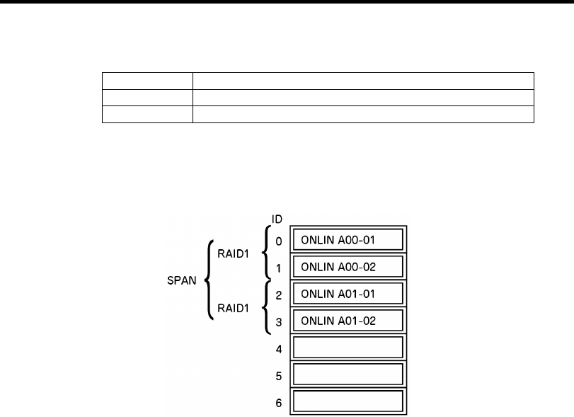
4-36 Configuring Your Server
(5) "Span: Sets Span.
Parameter Remarks
SPAN=NO Does not set span.
SPAN=YES Sets span.
When performing SPAN, create two or more sets of the same pack at pack creation,
as shown in the figure below.
STRIPING of RAID1
9. When all settings are completed, select "Accept" and then press Enter to create virtual
drive.
The created virtual drive is displayed in the "Virtual Drive Configured" screen.
10. After creating virtual drive, press Esc to close the screen.
Go back to the "Save Configuration?" screen and then select "Yes" to save the
configuration.
11. When the confirmation message shows that the configuration has been saved, press Esc
to return to the TOP menu screen.
12. On the TOP menu screen, select "Objects" → "Virtual Drive" → "View/Update
Parameters" to check virtual drive information.
13. Select "Initialize" in the TOP menu screen.
14. When the "Virtual Drives" screen appears, move the cursor to the virtual drive to be
initialized, and press Space.
The virtual drive is selected.
15. After selecting virtual drive, press F10 to start initialization.
A confirmation screen for execution appears. Select "Yes" to start initialization.
When the progress bar in the "Initialize Virtual Drive Progress" screen indicates 100%,
initialization is completed.

Configuring Your Server 4-37
16. Execute Check Consistency on the virtual drive that has been initialized.
See "Check Consistency" for details.
17. Press Esc to return to the TOP menu and exit from LSI Software RAID Configuration
Utility.
IMPORTANT:
Be sure to execute Check Consistency after creating configuration.
Be sure to execute Consistency Check if you have configured the
RAID drives by Express Setup.
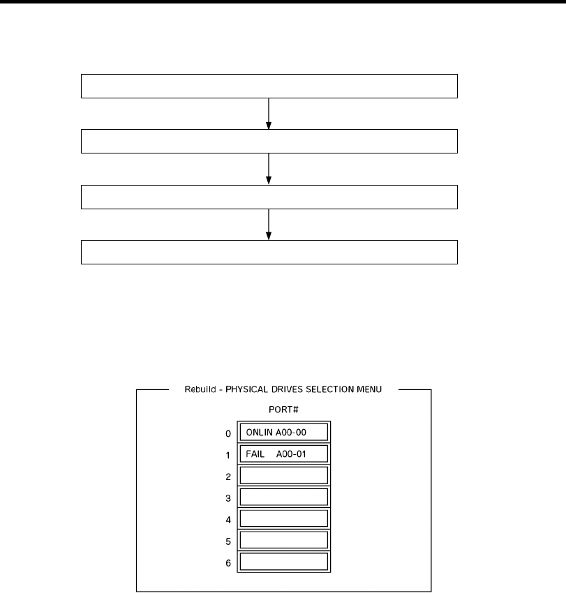
4-38 Configuring Your Server
Manual Rebuild
Replace hard disk drive
Run LSI Software RAID Configuration Utility
Execute rebuilding
Exit LSI Software RAID Configuration Utility
1. Replace a hard disk drive and turn on the server.
2. Run LSI Software RAID Configuration Utility.
3. Select "Rebuild" from the TOP menu.
The "Rebuild – PHYSICAL DRIVES SELECTION MENU" screen appears.
4. Move the cursor onto the hard disk drive displaying "FAIL," and then press Space to
select it. Multiple hard disk drives can be selected (simultaneous rebuilding.)
The "FAIL" indication for the hard disk drive selected starts blinking.
5. When hard disk drive has been selected, press F10 to start rebuilding.
6. When confirmation screen for execution appears. Select "Yes".
The rebuild process starts.
When the progress bar in the "Rebuild Physical Drives in Progress" screen indicates 100%,
rebuilding is completed.
7. Press Esc to return to the TOP menu and exit LSI Software RAID Configuration Utility.
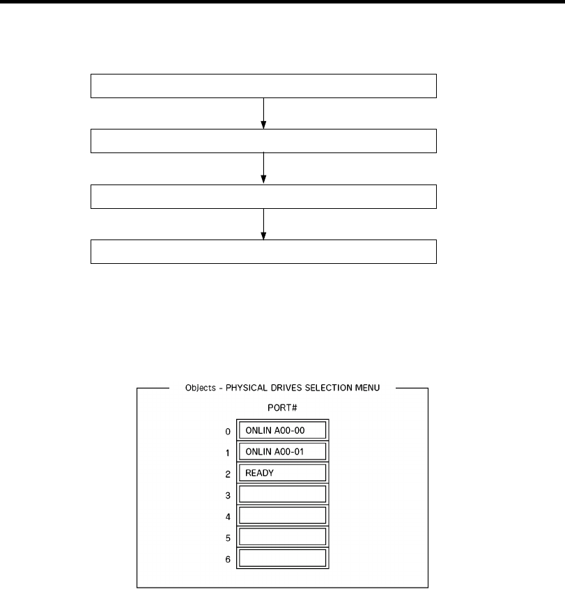
Configuring Your Server 4-39
Setting Hot Spare
Install a hard disk drive
Run LSI Software RAID Configuration Utility
Set for hot spare.
Exit LSI Software RAID Configuration Utility
1. Install a hard disk drive to be used as hot spare, and then turn on the server.
2. Run LSI Software RAID Configuration Utility.
3. Select "Objects" → "Physical Drive" from the TOP menu.
The "Objects - PHYSICAL DRIVES SELECTION MENU" screen appears.
4. Move the cursor onto the hard disk drive to be used as hot spare and press Enter.
5. The "Port #X" screen appears. Select "Make HotSpare."
6. A confirmation screen appears. Select "Yes."
The hard disk drive indication is changed to "HOTSP."
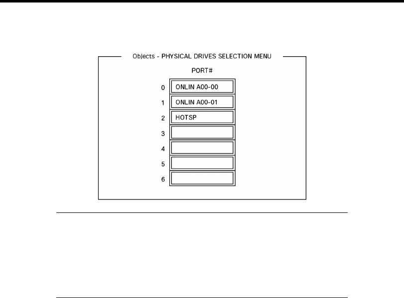
4-40 Configuring Your Server
7. Press Esc to return to the TOP menu and exit LSI Software RAID Configuration Utility.
IMPORTANT:
Select "Objects" → "Physical Drive" → "Port #X" → "Force
Offline" to cancel the hot spare setting.
When two or more hard disk drives (of the same capacity) are
assigned as hot spare, rebuilding is performed in order starting from
the one with the smaller CH number/ID number.

Configuring Your Server 4-41
Check Consistency
Run LSI Software RAID Configuration Utility
Perform Check Consistency
Exit LSI Software RAID Configuration Utility
1. Run LSI Software RAID Configuration Utility.
2. Select "Check Consistency" from the TOP menu.
The "Virtual Drives" screen appears.
3. Move the cursor onto the virtual drive to be checked, and press Space to select it.
4. When virtual drive has been selected, press F10 to start consistency check.
5. A confirmation screen for execution appears. Select "Yes".
The consistency check starts.
When the progress bar in the "Check Consistency Progress" screen indicates 100%, the
consistency check is completed.
6. Press Esc to return to the TOP menu and exit LSI Software RAID Configuration Utility.
IMPORTANT:
Be sure to execute Check Consistency after creating configuration.
Be sure to execute Consistency Check if you have configured the
RAID drives by Express Setup.

4-42 Configuring Your Server
Others
Clear Configuration
Clears configuration information. Select "Configure" → "Clear Configuration" from the
TOP menu. Executing "Clear Configuration" clears all configuration information on the
RAID Controller and hard disk drives. The configuration information on all channels of
the RAID Controller is also cleared.
NOTES:
When configuration information on the RAID Controller and that on
the hard disk drive do not match (excluding at replacement of faulty
RAID Controller), configuration mail fail if you select the
configuration information on the RAID Controller. In this case,
execute "Clear Configuration" to create configuration again.
LSI Software RAID Configuration Utility cannot delete each virtual
drive. Use Universal RAID Utility instead.
Force Online
Puts a hard disk drive being in the FAIL status online.
Select "Objects" → "Physical Drive" → (select hard disk drive) → "Force Online" from
the TOP menu.
Rebuild Rate
Sets the Rebuild Rate.
Select "Objects" → "Adapter" → "Sel. Adapter" → "Rebuild Rate" from the TOP menu.
Available value is between 0% and 100%. Default value (recommended) is 30%.
Hard disk drive information
Checks hard disk drive information.
Select "Objects" → "Physical Drive" → (select hard disk drive) → "Drive Properties"
from the TOP menu.

Configuring Your Server 4-43
LSI Software RAID Configuration Utility and Universal RAID Utility
You can use Universal RAID Utility for configuration and management, monitoring of RAID
System after start up operating system.
The point to keep in mind when I use Universal RAID Utility together with LSI Software RAID
Configuration Utility is as follows.
Terms
LSI Software RAID Configuration Utility and Universal RAID Utility are different in term. When
you use Universal RAID Utility together with LSI Software RAID Configuration Utility, please
convert terms by the following list.
Term of LSI Software RAID Configuration Utility Term of Universal RAID Utility
Adapter RAID Controller
Virtual Disk Logical Drive
Array Disk Array
Physical Drive Physical Device
Number and ID
The number to manage each component of disk array of Universal RAID Utility is different to LSI
Software RAID Configuration Utility.
Adapter and RAID Controller
LSI Software RAID Configuration Utility manages Adapter by a number beginning with 0. You can
see a number of Adapter where [Sel. Adapter] in [Objects] menu. Universal RAID Utility manages
RAID Controller by a number beginning with 1. You can see a number of RAID Controller where
[Number] in the property of RAID Controller on RAID Viewer.
Also, you can see the number of Adapter managed by LSI Software RAID Configuration Utility
where [ID] in the property of RAID Controller by Universal RAID Utility.
Logical Drive
LSI Software RAID Configuration Utility manages Logical Drive by a number beginning with 0.
You can see a number of Logical Drive where [Logical Drives] in [Objects] menu.
Universal RAID Utility manages Logical Drive by a number beginning with 1. You can see a
number of Logical Drive where [Number] in the property of Logical Drive on RAID Viewer.
Also, you can see the number of Logical Drive managed by LSI Software RAID Configuration
Utility where [ID] in the property of Logical Drive by Universal RAID Utility.

4-44 Configuring Your Server
Disk Array
LSI Software RAID Configuration Utility manages Disk Array by a number beginning with 0. You
can see a number of Disk Array where [Axx] of [Objects - PHYSICAL DRIVE SELECTION
MENU] DG X] in [Objects] menu.
Universal RAID Utility manages Disk Array by a number beginning with 1. You can see a number
of Disk Array where [Disk Array] in the property of Logical Drive on RAID Viewer.
Physical Drive and Physical Device
LSI Software RAID Configuration Utility manages Physical Drive by ID. You can see ID of
Physical Drive where [Port #] of [Objects - PHYSICAL DRIVE SELECTION MENU] DG X] in
[Objects] menu.
Universal RAID Utility manages Physical Device by a number beginning with 1 and ID. The ID is
same value of ID on LSI Software RAID Configuration Utility. You can see a number and ID of
Physical Device where [Number] and [ID] in the property of Physical Device on RAID Viewer.
Setting of Priority
LSI Software RAID Configuration Utility displays and sets Rebuild Priority and Consistency Check
Priority of RAID Controller by percentage. But, Universal RAID Utility uses three levels as
High/Middle/Low for them.
The setting value of LSI Software RAID Configuration Utility and the display level of Universal
RAID Utility
Item Setting value of LSI Software
RAID Configuration Utility Universal RAID Utility Level
15 to 100 High
8 to 14 Middle
Rebuild Priority
Rebuild Rate (LSI Software
RAID Configuration Utility) 0 to 7 Low
15 to 100 High
8 to 14 Middle
Consistency Check Priority
Chk Const Rate (LSI Software
RAID Configuration Utility) 0 to 7 Low

Configuring Your Server 4-45
The setting level of Universal RAID Utility and the setting value
Item Setting level of Universal
RAID Utility Setting value
High 20
Middle 10
Rebuild Priority
Rebuild Rate (LSI Software
RAID Configuration Utility) Low 5
High 20
Middle 10
Consistency Check Priority
Chk Const Rate (LSI Software
RAID Configuration Utility) Low 5
NOTES:
LSI Software RAID Configuration Utility can set FGI Rate
(Foreground Initialize) and BGI Rate (Background Initialize
Priority). But Universal RAID Utility can't set it.
Universal RAID Utility can set Initialization Priority, but it can't set
it to the LSI Embedded MegaRAID™. Therefore, Universal RAID
Utility doesn't display [Initialization Priority] in the property of
RAID Controller.
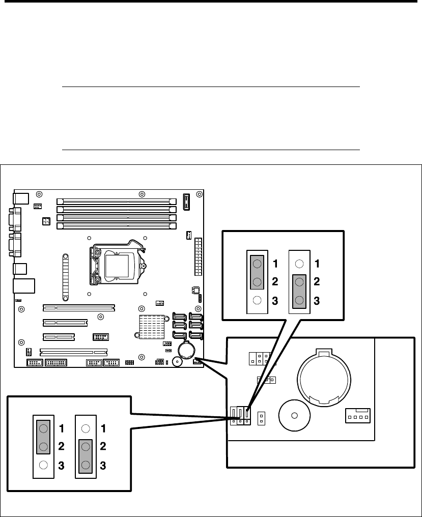
4-46 Configuring Your Server
CONFIGURING MOTHER BOARD JUMPERS
You can use the following procedure to clear the CMOS data in the server.
IMPORTANT:
Clearing the CMOS data resumes the factory-set configuration data.
Do not change any other switch settings. Any change may cause the
server to fail or malfunction.
Clear
Protect
(Factory-Set)
Jumper switch to clear password
(PASSWORD_CLR)
Jumper switch to clear CMOS
(CMOS_CLR)
Mother board
Clear
Protect
(Factory-Set)
Configuring Your Server 4-47
The following describe the clearing procedure.
WARNING
Do not disassemble, repair, or alter the server.
Never attempt to disassemble, repair, or alter the server on any occasion other
than described in this manual. Failure to follow this instruction may cause an
electric shock or fire as well as malfunctions of the server.
Clearing CMOS Data
1. See the section "Preparing for Installation and Removal" as described in Chapter 9 of this
guide to prepare.
2. Remove the side cover (see Chapter 9).
3. Install the jumper on position 2-3 (CMOS clear) of the jumper block.
See the figure on the previous page to find the location of this jumper.
4. After five seconds later, reinstall the jumper to original position (1-2).
5. Reinstall the side cover and connect the interface cables.
6. Connect the power cord to the server and then turn on the power.
7. Press F2 at the prompt to run the BIOS SETUP utility, and select "Load Setup Default" at
the Exit menu.

4-48 Configuring Your Server
Clearing Password
1. See the section "Preparing for Installation and Removal" as described in Chapter 9 of this
guide to prepare.
2. Remove the side cover (see Chapter 9).
3. Check the location of jumper switch to clear the password.
4. Change jumper switch setting according to the figure on Page 4-46.
5. Plug the power cord, connect the keyboard/mouse and display unit to your server, then
turn on the server.
6. POST stops at the error message shown below.
ERROR
8151 Password Cleared By Jumper
Press <F1> to resume, <F2> to Setup
7. Turn off the power of the server, and unplug the power cord from your server. Restore the
jumper strap removed in Step 4.
8. Install the side cover, and connect cables for peripheral devices and power cord.

Chapter 5
Installing the Operating System with Express
Setup
This section describes information on using Express Setup to install and configure the following
operating systems to the server.
Microsoft® Windows Server® 2008 R2 Standard
Microsoft® Windows Server® 2008 Standard 64-bit (x64) Edition
Microsoft® Windows Server® 2008 Standard 32-bit (x86) Edition
Microsoft® Windows Server® 2003 R2 Standard Edition
To use the server with the other operating systems described in this section, contact your service
representative.
IMPORTANT: Before installing the operating system, adjust the
system date and time by using the BIOS setup utility "SETUP." See
Chapter 4 for detail.
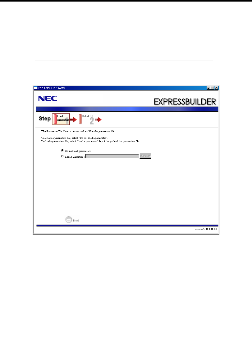
5-2 Installing the Operating System with Express Setup
About Express Setup
"Express Setup" helps you to install the Windows Operating System. The setup automatically
configures the RAID System and installs the Operating System and some management software.
IMPORTANT: Executing the Express Setup erases all data on the
hard disk drive.
You can also use "Parameter File" at "Express Setup" in order to save or backup parameters for
installation.
If you want to set up the server as before, execute the Express Setup with the parameter file you
have saved before.
NOTES:
If you want to create a parameters file, have a blank floppy disk
(MS-DOS 1.44MB format) ready.
When using a floppy disk, a Flash FDD or USB FDD is required.
If you want to use the drivers located on the "OEM-Disk for Mass
Storage Device" that ships with optional boards, a parameters file
is mandatory.
You can create a parameters file in advance using "Parameter File
Creator" included in NEC EXPRESSBUILDER.

Installing the Operating System with Express Setup 5-3
Windows Server 2008 R2
This section explains how to install Windows Server 2008 R2 by using the Express Setup.
IMPORTANT: The Scalable Networking Pack (SNP) function is
disabled in the system that installed by Express Setup.
The setting of SNP function may affect the system performance, so
refer to the attention of SNP detail in the following site before setting
it.
http://www.nec.com/global/prod/express/
NOTE: If you install Windows Server 2008 R2 without using Express
Setup, see Appendix D.
Notes on Windows Installation
This section explains the notes on the Windows installation.
Confirm these notes before starting the Express Setup.
About the Windows Family
This computer supports the following Windows editions:
Windows Server 2008 R2 Standard (hereinafter, referred to as "Windows Server 2008
R2")
On installing other OS, contact sales dealer or the maintenance service representative.
BIOS Settings
Confirm the BIOS settings described in Chapter 4 before installing Windows Server 2008 R2.
Service Pack Which EXPRESSBUILDER Supports
The NEC EXPRESSBUILDER DVD attached to the server supports following combination of the
OS installation media and Service Pack.
Windows Server 2008 R2
– OS installation media (No Service Pack)

5-4 Installing the Operating System with Express Setup
Supported Mass Storage Controllers
The NEC EXPRESSBUILDER DVD attached to your system supports the following mass storage
controllers for installation.
Controllers supporting installation of OS with Express Setup
– N8103-109 RAID Controller (128 MB, RAID0/1/5/6)*
– N8103-116A RAID Controller (128 MB, RAID0/1)*
– N8103-117A RAID Controller (128 MB, RAID0/1/5/6)*
– Onboard RAID Controller (LSI Embedded MegaRAID™)
Other controllers
– N8103-75 SCSI Controller*
– N8103-104A SAS Controller*
– N8103-107 SCSI Controller*
* Option
About the Hardware Components
When you install the Windows Server 2008 R2, Express Setup requires several preparations if this
computer uses the following hardware components.
Installing on the Mirrored Volume
When re-installing the OS to a hard disk drive which has been upgraded to Dynamic Disk, only the
simple dynamic volume is available for installation.
If you want to install the OS on a volume that is mirrored using Disk Management, invalidate the
mirroring and reset to the basic disk before the installation, and validate the mirroring again after the
installation.
You can create, invalidate, or delete the mirror volume by using Disk Management in Computer
Management.
Mounting MO Device
Do not mount an MO device on this computer during the Windows installation.
About Removable Media
Do not set removable media, such as DAT and LTO, into the device mounted on this computer
during the Windows installation.

Installing the Operating System with Express Setup 5-5
Connecting Hard Disk Drive
If you create multiple logical drives in your system, see "Re-installing the Operation System if
Multiple Logical Drives Exist" (5-92).
Re-installing to the Hard Disk Drive which has been upgraded to Dynamic
Disk
You cannot re-install Windows Server 2008 R2 with the current partition of the hard disk drive
upgraded to Dynamic Disk kept remained.
If you want to keep the current partition remained, see Appendix D to re-install the system.
Peripheral Devices such as RDX
Depending on your hardware configuration, some peripheral devices need to be removed or
disabled before starting setup. Refer to the instruction manual which came with the peripheral
device for pertinent information, and proceed accordingly.

5-6 Installing the Operating System with Express Setup
About the System Partition Size
When the system is Windows Server 2008 R2
Required partition size =
size required to install OS + paging file size + dump file size + application size
Size required to install OS = 8,000MB (Full Installation)
or
= 3,500MB (Server Core Installation)
Paging file size (recommended) = Installed memory size * 1.5
Dump file size = Installed memory size + 300MB
Application size = Required size
IMPORTANT:
The above-mentioned partition size is the minimum partition size
required for system installation. Ensure sufficient partition size for
system operation.
Following numbers are the recommended size.
– Full Installation: 32,768MB (32GB) or more
– Server Core Installation: 10,240MB (10GB) or more
*1GB = 1,024MB
The above-mentioned paging file size is recommended for
collecting debug information (memory dump). The paging file
with initial size large enough to store the dump file in the Windows
Partition is required.
Correct debug information might not be able to be collected due to
virtual memory shortage when the paging file is insufficient, so set
an enough size of the paging file with the entire system.
Regardless of the size of the mounted memory, or the Write
debugging information (type of memory dump), the maximum size
of the dump file is 'The size of the mounted memory + 300MB'.
If you install any application program or the like, add necessary
space to the partition to install these programs.
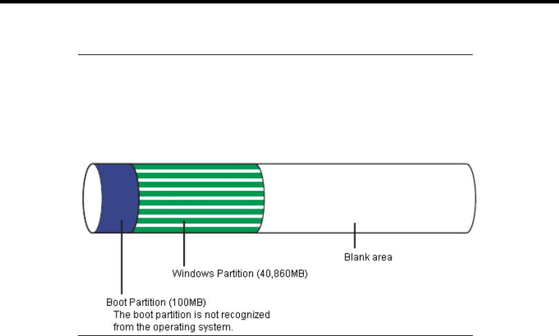
Installing the Operating System with Express Setup 5-7
NOTE: When new partition is created, initial 100MB is assigned as
boot partition by Windows OS.
Example:
If you make a partition of 40,960MB (40GB), usable space will be
40,960MB – 100MB = 40,860MB.
The partition size required for a system with an installed memory size of 1GB (1,024MB) and a full
installation of the operating system:
8,000MB + (1,024MB * 1.5) + (1,024MB + 300MB) + application size
= 10,860MB + application size.
If the provided partition size is smaller than that required to install the OS and paging file, expand
the partition size or utilize a larger disk. If your system does not have a sufficient dump file size,
divide the required file space into multiple disks by performing the steps below:
1. Set the system partition size to a size sufficient to install the OS and paging file.
2. See "Setting for Solving Problems" to write the debug information of the dump file onto
another disk.
If there is not enough disk space to write the debug information, add another disk for the dump file.
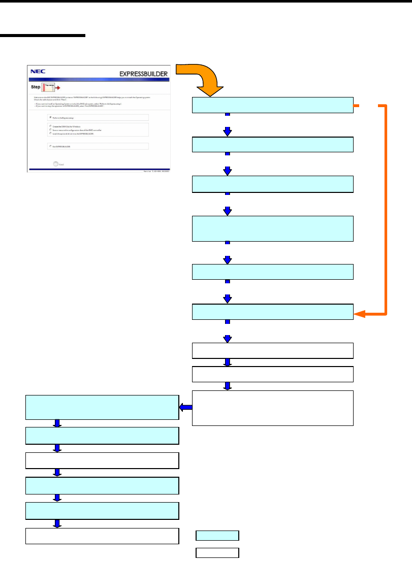
5-8 Installing the Operating System with Express Setup
Flow of Setup
Loading parameters (Step 2)
Select the operating system (Step 3)
Next
RAID configuration (Step 4)
Next
Windows Confirm Setting / Input
(Steps 5 to 10)
Next
Save parameters (Step 11)
Next
Start Express Setup (Step 12)
Next
RAID Configuration
Perform
Create the OS partition / format
Copying Windows driver
↓
Copying Selected Application
Remove the Floppy Disk and CD/DVD-ROM
from the Drive
Insert Windows DVD-ROM
The installation is completed. : Process that needs to input or select
: Process that proceeds automatically
Skip
Install OS Automatically
Agree Software License Agreement
Log on
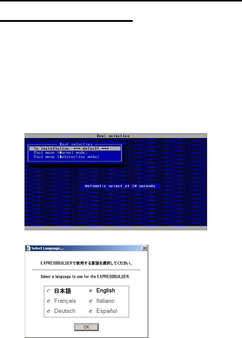
Installing the Operating System with Express Setup 5-9
Installing the Windows Server 2008 R2
Express Setup proceeds the setup by selecting or inputting several parameters on the wizard. You
can also save the parameters to a floppy disk as a parameters file.
1. Turn the power of peripheral device on, and then turn on the server.
2. Insert the NEC EXPRESSBUILDER DVD into the optical disk drive of the server.
3. Press the RESET switch or press Ctrl, Alt, and Delete to reboot from the NEC
EXPRESSBUILDER. (You may also turn off and then on again to reboot the server.)
The system will boot from the DVD and NEC EXPRESSBUILDER starts.
Select "Os installation *** default ***" from the Boot selection menu.
(If you do not hit any key, "Os installation" is selected automatically.)
The Top menu will appear.
4. Select [English] from the Select Language, click [OK].
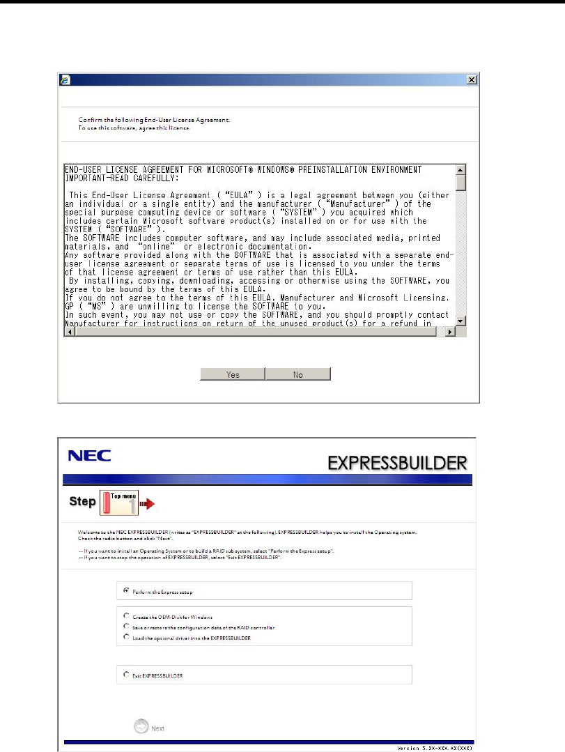
5-10 Installing the Operating System with Express Setup
5. When the Software Licence Agreement screen of Windows PE appears, click [Yes].
6. Select [Perform the Express setup] from the Top Menu, click [Next].

Installing the Operating System with Express Setup 5-11
7. [Load parameters] steps are displayed.
[Do not load parameters]
(1) Select [Do not load parameters].
(2) Click [Next].
IMPORTANT: The setup using a parameter file saved in the Flash
FDD is not supported.
NOTE: If a floppy disk drive is not connected, select this item.
[Load parameters]
(1) Insert the floppy disk containing the parameters file.
(2) Select [Load parameters], enter the file path of the parameters file into the text box.
(3) Click [Next].
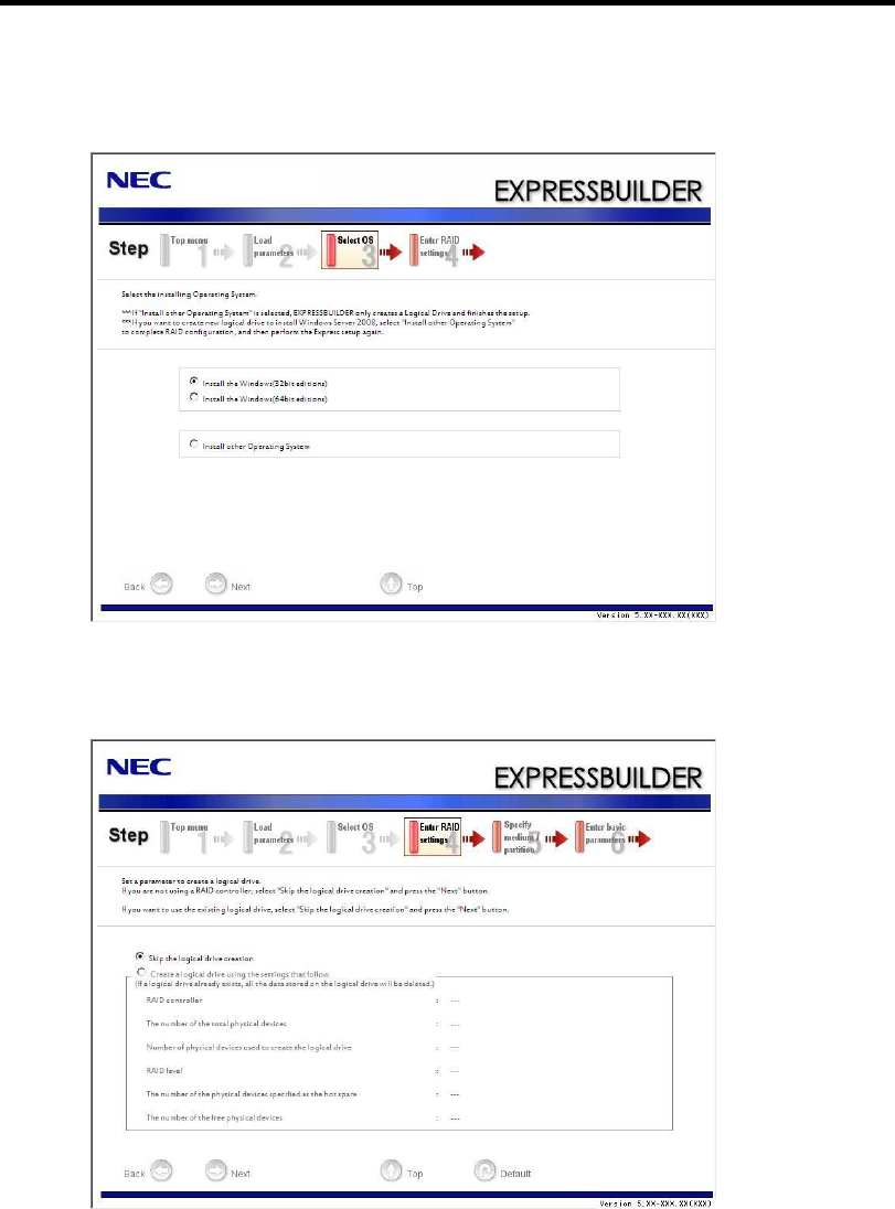
5-12 Installing the Operating System with Express Setup
8. Select the installing Operating System.
Select [Install the Windows (64bit editions)] from the menu, click [Next].
9. Enter the setting of a logical drive.
[Enter RAID settings] steps are displayed. Confirm the parameters, modify if necessary,
and then click [Next].
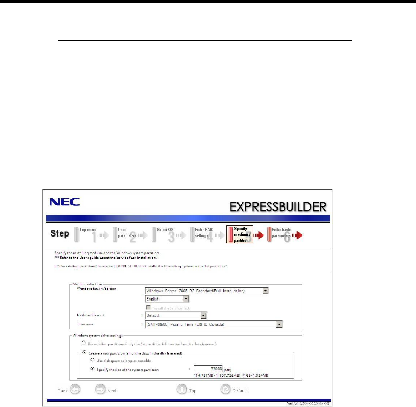
Installing the Operating System with Express Setup 5-13
NOTES:
You can use only the physical devices that have same model
number to configure logical drive.
If the process is not finished normally, the driver may not be stored
in the EXPRESSBUILDER. Refer to "Optional Board Supported
by NEC EXPRESSBUILDER" described earlier in this chapter.
10. Specify the installing medium and the Windows system partition.
[Specify medium / Partition] steps are displayed. Confirm the parameters, modify if
necessary, and then click [Next].

5-14 Installing the Operating System with Express Setup
IMPORTANT:
About partition size
– Specify the partition size larger than required minimum size for
OS installation.
– Do not specify larger partition size than the capacity of
connected hard disk drive.
– You can not specify a logical drive larger than 2,097,144MB at
RAID system.
If you select "Create a new partition" at "Windows system drive
settings", the contents of the hard disk will be all deleted.
If "Use existing partitions" is selected, EXPRESSBUILDER
installs the Operating System to the Windows partition (The Boot
partition (if it exists) and the Windows partition are deleted). The
data in the other partition is kept if the system has two or more
partitions. (See the figure below.)
Boot
Partition
Deleted
Windows
Partition
Deleted
User Data
Partition
Retained
You can not re-install the system with the existing partition that is
upgraded to Dynamic Disk remained. Do not select "Use existing
partitions" at "Windows system drive settings".

Installing the Operating System with Express Setup 5-15
11. Enter the user information.
[Enter basic parameters] steps are displayed. Confirm the parameters, modify if necessary,
and then click [Next].
IMPORTANT: Computer name and Administrator password that
satisfy the next condition, are required.
– More than 6 characters
– Contains characters from three of the following categories
(numbers, uppercase letters, lowercase letters, and signs).

5-16 Installing the Operating System with Express Setup
12. Enter the setting of the network protocol.
[Enter Network Protocol] steps are displayed. Confirm the parameters, modify if
necessary, and then click [Next].
13. Enter the domain or workgroup name to be used.
[Enter domain account] steps are displayed. Confirm the parameters, modify if necessary,
and then click [Next].
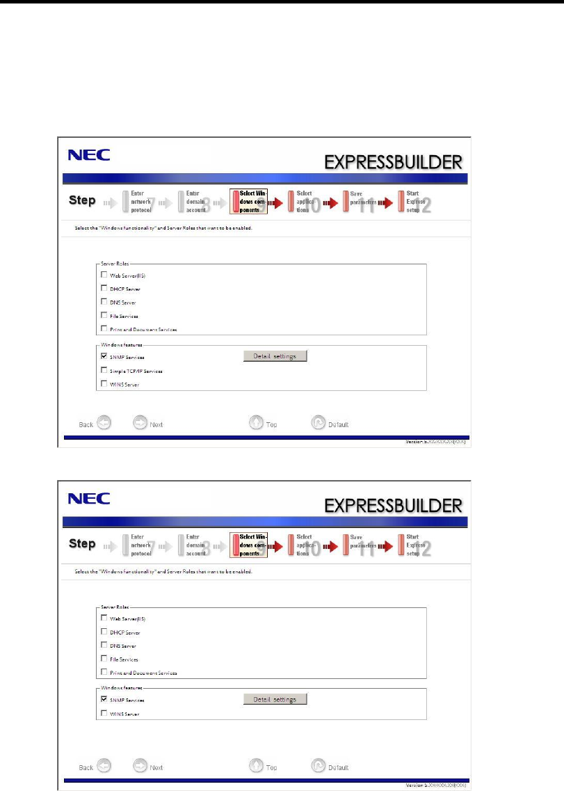
Installing the Operating System with Express Setup 5-17
14. Select the installing components.
[Select Windows components] steps are displayed. Confirm the parameters, modify if
necessary, and then click [Next].
<Full Installation>
<Server Core Installation>

5-18 Installing the Operating System with Express Setup
15. Select the installing applications.
[Select applications] steps are displayed. Confirm the parameters, modify if necessary, and
then click [Next].
16. Save the parameters.
[Save parameters] steps are displayed.
If you want to save the parameters , set the free formatted floppy disk.
Select [Save parameters], enter the file path of the parameters files into the text box and
click [Next].
If not, select [Do not save parameters].

Installing the Operating System with Express Setup 5-19
17. The Express Setup will start when you click [Perform] in [Start Express setup] step.
18. Remove NEC EXPRESSBUILDER DVD from the optical disk drive according to the
message.
If you proceed the setup by using setup parameter file, remove the floppy disk from the
floppy disk drive.
19. Insert Windows Server 2008 R2 DVD-ROM into the optical disk drive.
NOTE: Windows Server 2008 R2 and selected applications will be
installed automatically and reboots several times.

5-20 Installing the Operating System with Express Setup
20. [Agree Software License Agreement] screen appears. (Full Installation only)
Read the license terms carefully. If you agree, select I accept the license terms, and then
click [Next].
21. When the following message appears, press Ctrl + Alt + Del.
22. Log on to the system.
<Full Installation>
When the following screen appears, enter your password into "Password", and click .
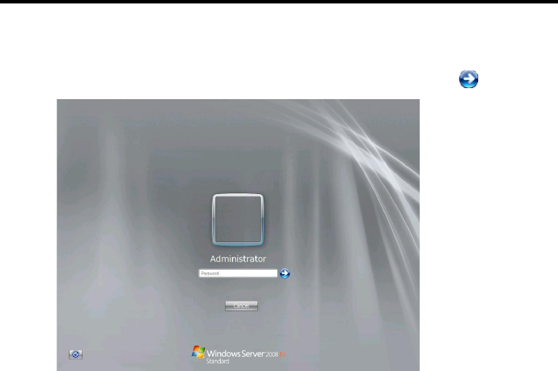
Installing the Operating System with Express Setup 5-21
<Server Core Installation>
In the following screen, enter your password into "Password", and click .
Hereinafter, proceed operations according to the message.
Now the Setup using Express Setup has completed.
After Express Setup has completed, be sure to execute the tasks described in "Installing and Setting
Device Drivers".

5-22 Installing the Operating System with Express Setup
Installing and Setting Device Drivers
Follow these steps to install and configure the device drivers.
LAN Driver and PROSet
The LAN driver and PROSet have been installed automatically while your system was being
updated in the previous section.
NOTE: To change the LAN driver and PROSet settings, log on to the
system from a local console using an administrator account. Remotely
changing the settings by using the operating system’s remote desktop
feature is not supported.
Network Driver
Specify the details of network driver.
Two standard network drivers that are mounted will be installed automatically, but the link speed
and Duplex mode need to be specified manually.
1. Open the [Device Manager].
2. Double-click [(Network Adapter Name)] in the list.
3. Click the [Link Speed] and specify the [Speed & Duplex] value the same as the value
specified for HUB.
4. Click [OK].
5. Restart the system.
Also, add or delete any protocols and services if necessary.
You can operate the process on the property dialog box for local area network which can be
appeared from [Network and Dial-up Connection].
NOTE: We recommend you to add [Network Monitor] at [Adding
Services].
[Network Monitor] can monitor the frame (or the packet) that the
computer installing [Network Monitor] sends or receives. This tool is
valuable when analyzing network trouble. For information on how to
install the tool, see the "Setting for Solving Problems" described later
in this chapter.

Installing the Operating System with Express Setup 5-23
Optional Network Board Driver (N8104-121/125A/126)
The drivers for Optional Network Board Driver (N8104-121/125A/126) are automatically installed
by Windows Plug-and-Play. You do not need to install them manually.
Setup Team
Adapter Fault Tolerance (AFT) is a feature that creates a group containing more than one adapter
and automatically converts the process of the working adapter to the other adapter in the group
when any trouble occurred on that adapter.
Adaptive Load Balancing (ALB) is a feature that creates a group containing more than one adapter
and enhances the throughput by operating packet transmission from the server by all the adapters.
This feature includes AFT feature.
Switch Fault Tolerance (SFT) is a feature that provides a failover relationship between two ports
when each port is connected to a separate switch.
SFT supports two ports per team.
Static Link Aggregation (SLA) accounts for the GEC and 802.3ad static protocols.
SLA is a switch-assisted teaming mode and requires configuring ports at both ends of the link:
server interfaces and switch ports.
IMPORTANT:
AFT/ALB setup must be operated after system update and
restarting the system.
All the adapters specified as a group of Adapter Teaming must
exist on the same LAN. If they are connected to the separate
switches, they will not work normally.
The adapters specified as a group of Adaptive Load Balancing
(ALB) can be connected to only Switching Hub.
When exchange the mother board or option network card, make
sure to remove the adapter team before exchanges and recreate the
adapter team after exchange complete.
Confirm the port setting of switching hub (L2) matches the server
network adapter Teaming mode.
Teaming is not supported with Windows Server Core.

5-24 Installing the Operating System with Express Setup
Create Team
1. Open the [Device Manager].
2. Open [Network adapters] → [Intel(R) xxx] properties.
3. Click [Teaming] tab and check the [Team this adapter with other adapters] check box.
Click [New Team].
4. Fill the name of the team in [Specify a name for the team] and click [Next].
5. Include the adapter to the team and click [Next].
6. Select a team mode, and then click [Next].
IMPORTANT: Following team types are supported.
Adapter Fault Tolerance
Adaptive Load Balancing
Static Link Aggregation
Switch Fault Tolerance
7. Click [Finish].
IMPORTANT: Teaming an adapter with standard network adapter and
optional network adapter will cause the following message appear.
Click [OK] and continue the setting.
"One or more adapters in the team do not support true NDIS6.20
Receive-Side Scaling, Receive-Side Scaling will be disabled for the
team, Disabling Receive-Side Scaling will negatively impact the
performance of the team."
8. Click [TEAM: "Team name"] from [Device manager] → [Network adapters] to modify
the team.
Click [Settings] tab and click [Modify Team] button.
9. Refer to the following procedure to set the team member adapter priority status.
– Set Primary
Point the adapter and click [Set Primary] button.
– Set Secondary
Point the adapter and click [Set Secondary] button.

Installing the Operating System with Express Setup 5-25
NOTE: Adapter priority config can be confirmed by the following
procedure:
1. Click [TEAM: "Team name"] from [Device manager]→[Network
adapters].
2. Click [Settings] and confirm Adapters in team list.
10. Click [Test Switch] → [Run test] to confirm the adapter team is properly setup.
Confirm the result in [Test results]
11. Restart the system.

5-26 Installing the Operating System with Express Setup
Remove Team
1. Open the [Device Manager].
2. Click [Network adapters], and open [TEAM: "Team name"] properties.
3. Click [Setting] tab.
4. Click [Remove Team] button.
5. Click [Yes] to the message.
6. Confirm [TEAM: "Team name"] adapter in not existing in [Network adapters] tree and
reboot the system.
Setting WOL
Refer to the following procedure to enable WOL.
1. Start Device Manager.
2. Point to [Network adapters] and double click [Intel(R) 82547L Gigabit Network
Connection] to open the adapter [Properties].
3. Click [Power Management] tab and change setting in [Wake On LAN] according to the
following list.
Setting item Change setting
"Wake On Magic Packet" ON
"Wake on Magic Packet from power off state" ON
"Wake on Link" OFF
"Wake on Pattern Match " OFF
NOTES:
[Power Saver Options] setting is not necessary to change.
Above setting will be maintained until manually resetting are
executed.
IMPORTANT: The parameters of [Wake On LAN] will not exist, if
the network ports are not available for WOL.
4. Click [OK].
5. Restart the system.

Installing the Operating System with Express Setup 5-27
Graphics Accelerator Driver
If you use standard graphics accelerator drivers, update your system with NEC
EXPRESSBUILDER DVD attached to your system.
Standard graphics accelerator drivers will be installed automatically.
Refer to "Graphics Accelerator Driver" described in Appendix D-27 when you want to reinstall the
driver individually.
Installing SCSI Controller Driver (N8103-75/107)
If you use the SCSI Controller N8103-75/107, you do not need to install the driver manually. It is
automatically installed by Windows Plug-and-Play.
Installing SAS Controller Driver (N8103-104A)
If you use the SAS Controller N8103-104A, you do not need to install the driver manually. It is
automatically installed by Windows Plug-and-Play.
Setting for Solving Problems
Setup your computer in advance so that it can recover from any trouble precisely and as soon as
possible when it should occur.
For more information, refer to Page 5-80.
BitLocker
For BitLocker, hotfix is provided by Microsoft. Before applying hotfix, check the information
written by Microsoft carefully.
For more information, visit http://support.microsoft.com/kb/975496/en-us.

5-28 Installing the Operating System with Express Setup
Windows Server 2008
This section explains how to install Windows Server 2008 by using the Express Setup.
IMPORTANT: The Scalable Networking Pack (SNP) function is
disabled in the system that installed by Express Setup.
The setting of SNP function may affect the system performance, so
refer to the attention of SNP detail in the following site before setting
it.
http://www.nec.com/global/prod/express/
NOTE: If you install Windows Server 2008 without using Express
Setup, see Appendix E.
Notes on Windows Installation
This section explains the notes on the Windows installation.
Confirm these notes before starting the Express Setup.
About the Windows Family
This computer supports the following Windows editions:
Windows Server 2008 Standard 64-bit (x64) Edition (hereinafter, referred to as "Windows
Server 2008")
Windows Server 2008 Standard 32-bit (x86) Edition (hereinafter, referred to as "Windows
Server 2008")
On installing other OS, contact sales dealer or the maintenance service representative.
BIOS Settings
Confirm the BIOS settings described in Chapter 4 before installing Windows Server 2008.

Installing the Operating System with Express Setup 5-29
Service Pack Which EXPRESSBUILDER Supports
The NEC EXPRESSBUILDER DVD attached to the server supports following combination of the
OS installation media and Service Pack.
Windows Server 2008
– OS installation media (with Service Pack 2)
– OS installation media (No Service Pack) + Service Pack 2
– OS installation media (No Service Pack)
Supported Mass Storage Controllers
The NEC EXPRESSBUILDER DVD attached to your system supports the following mass storage
controllers for installation.
Controllers supporting installation of OS with Express Setup
– N8103-109 RAID Controller (128 MB, RAID0/1/5/6)*
– N8103-116A RAID Controller (128 MB, RAID0/1)*
– N8103-117A RAID Controller (128 MB, RAID0/1/5/6)*
– Onboard RAID Controller (LSI Embedded MegaRAID™)
Other controllers
– N8103-75 SCSI Controller*
– N8103-95 SCSI Controller*
– N8103-104A SAS Controller*
– N8103-107 SCSI Controller*
* Option
About the Hardware Components
When you install the Windows Server 2008, Express Setup requires several preparations if this
computer uses the following hardware components.
Installing on the Mirrored Volume
When re-installing the OS to a hard disk drive which has been upgraded to Dynamic Disk, only the
simple dynamic volume is available for installation.
If you want to install the OS on a volume that is mirrored using Disk Management, invalidate the
mirroring and reset to the basic disk before the installation, and validate the mirroring again after the
installation.
You can create, invalidate, or delete the mirror volume by using Disk Management in Computer
Management.

5-30 Installing the Operating System with Express Setup
Mounting MO Device
Do not mount an MO device on this computer during the Windows installation.
About Removable Media
Do not set removable media, such as DAT and LTO, into the device mounted on this computer
during the Windows installation.
Connecting Hard Disk Drive
If you create multiple logical drives in your system, see "Re-installing the Operation System if
Multiple Logical Drives Exist" (5-92).
Re-installing to the Hard Disk Drive which has been upgraded to Dynamic
Disk
You cannot re-install Windows Server 2008 with the current partition of the hard disk drive
upgraded to Dynamic Disk kept remained.
If you want to keep the current partition remained, see Appendix E to re-install the system.
Peripheral Devices such as RDX
Depending on your hardware configuration, some peripheral devices need to be removed or
disabled before starting setup. Refer to the instruction manual which came with the peripheral
device for pertinent information, and proceed accordingly.

Installing the Operating System with Express Setup 5-31
About the System Partition Size
When the system is Windows Server 2008 64-bit (x64) Edition:
Required partition size =
size required to install OS + paging file size + dump file size + application size
Size required to install OS = 11,600MB (Full Installation)
12,300MB (Full Installation with Service Pack 2)
16,720MB (Full Installation + Service Pack 2)
or
= 4,100MB (Server Core Installation)
4,800MB (Server Core Installation with Service Pack
2)
9,220MB (Server Core Installation + Service Pack 2)
Paging file size (recommended) = Installed memory size * 1.5
Dump file size = Installed memory size + 300MB
Application size = Required size
IMPORTANT:
The above-mentioned paging file size is recommended for
collecting debug information (memory dump). The paging file
with initial size large enough to store the dump file in the boot
drive is required.
Correct debug information might not be able to be collected due to
virtual memory shortage when the paging file is insufficient, so set
an enough size of the paging file with the entire system.
Regardless of the size of the mounted memory, or the Write
debugging information (type of memory dump), the maximum size
of the dump file is 'The size of the mounted memory + 300MB'.
If you install any application program or the like, add necessary
space to the partition to install these programs.
Example:
The partition size required for a system with an installed memory size of 1GB (1,024MB) and a full
installation of the operating system:
11,600MB + (1,024MB * 1.5) + (1,024MB + 300MB) + application size
= 14,460MB + application size.
If the provided partition size is smaller than that required to install the OS and paging file, expand
the partition size or utilize a larger disk. If your system does not have a sufficient dump file size,
divide the required file space into multiple disks by performing the steps below:
1. Set the system partition size to a size sufficient to install the OS and paging file.
2. See "Setting for Solving Problems" to write the debug information of the dump file onto
another disk.
If there is not enough disk space to write the debug information, add another disk for the dump file.

5-32 Installing the Operating System with Express Setup
When the system is Windows Server 2008 32-bit (x86) Edition
Required partition size = size required to install OS + paging file size + dump
file size + application size
Size required to install OS = 6,300MB (Full Installation)
9,300MB (Full Installation with Service Pack 2)
9,400MB (Full Installation + Service Pack 2)
or
= 2,200MB (Server Core Installation)
5,200MB (Server Core Installation with Service
Pack 2)
5,300MB (Server Core Installation + Service Pack
2)
Paging file size (recommended) = Installed memory size * 1.5
Dump file size = Installed memory size + 300MB
Application size = Required size
IMPORTANT:
The above-mentioned paging file size is recommended for
collecting debug information (memory dump). The paging file
with initial size large enough to store the dump file in the boot
drive is required.
Correct debug information might not be able to be collected due to
virtual memory shortage when the paging file is insufficient, so set
an enough size of the paging file with the entire system.
Depending on system configuration, 4096MB or more per partition
might not be able to be set to the paging file size.
Set it to 4095MB when the message to ask a value that is smaller
than 4096MB is displayed.
The maximum dump file size for the system with more than 2GB
memory mounted is '2048MB + 300MB'.
If you install any application program or the like, add necessary
space to the partition to install these programs.
Example:
The partition size required for a system with an installed memory size of 1GB (1,024MB) and a full
installation of the operating system:
6,300MB + (1,024MB * 1.5) + 1,024MB + 300MB + application size
= 9,160MB + application size.
If the partition where the operating system is installed is smaller than that required to install the OS
and paging file, expand the partition size or utilize a larger disk. If your system does not have a
sufficient dump file size, divide the required file space into multiple disks by performing the steps
below:
1. Set the partition size to a size sufficient to install the OS and paging file.
2. See "Setting for Solving Problems" to write the debug information of the dump file on to
another disk.
If there is not enough disk space to write the debug information, add another disk for the dump file.
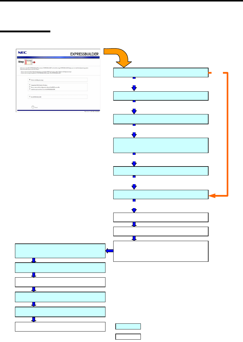
Installing the Operating System with Express Setup 5-33
Flow of Setup
Loading parameters (Step 2)
Select the operating system (Step 3)
Next
RAID configuration (Step 4)
Next
Windows Confirm Setting / Input
(Steps 5 to 10)
Next
Save parameters (Step 11)
Next
Start Express Setup (Step 12)
Next
RAID Configuration
Perform
Create the OS partition / format
Copying Windows driver
↓
Copying Selected Application
Remove the Floppy Disk and CD/DVD-ROM
from the Drive
Insert Windows DVD-ROM
The installation is completed. : Process that needs to input or select
: Process that proceeds automatically
Skip
Install OS Automatically
Agree Software License Agreement
Log on
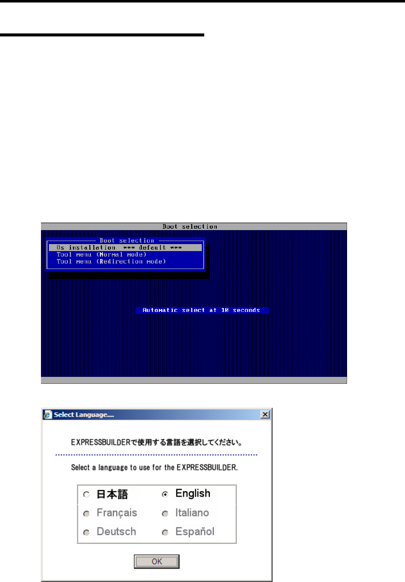
5-34 Installing the Operating System with Express Setup
Installing the Windows Server 2008
Express Setup proceeds the setup by selecting or inputting several parameters on the wizard. You
can also save the parameters to a floppy disk as a parameters file.
1. Turn the power of peripheral device on, and then turn on the server.
2. Insert the NEC EXPRESSBUILDER DVD into the optical disk drive of the server.
3. Press the RESET switch or press Ctrl, Alt, and Delete to reboot from the NEC
EXPRESSBUILDER. (You may also turn off and then on again to reboot the server.)
The system will boot from the DVD and NEC EXPRESSBUILDER starts.
Select "Os installation *** default ***" from the Boot selection menu.
(If you do not hit any key, "Os installation" is selected automatically.)
The Top menu will appear.
4. Select [English] from the Select Language, click [OK].

Installing the Operating System with Express Setup 5-35
5. When the Software Licence Agreement screen of Windows PE appears, click [Yes].
6. Select [Perform the Express setup] from the Top Menu, click [Next].
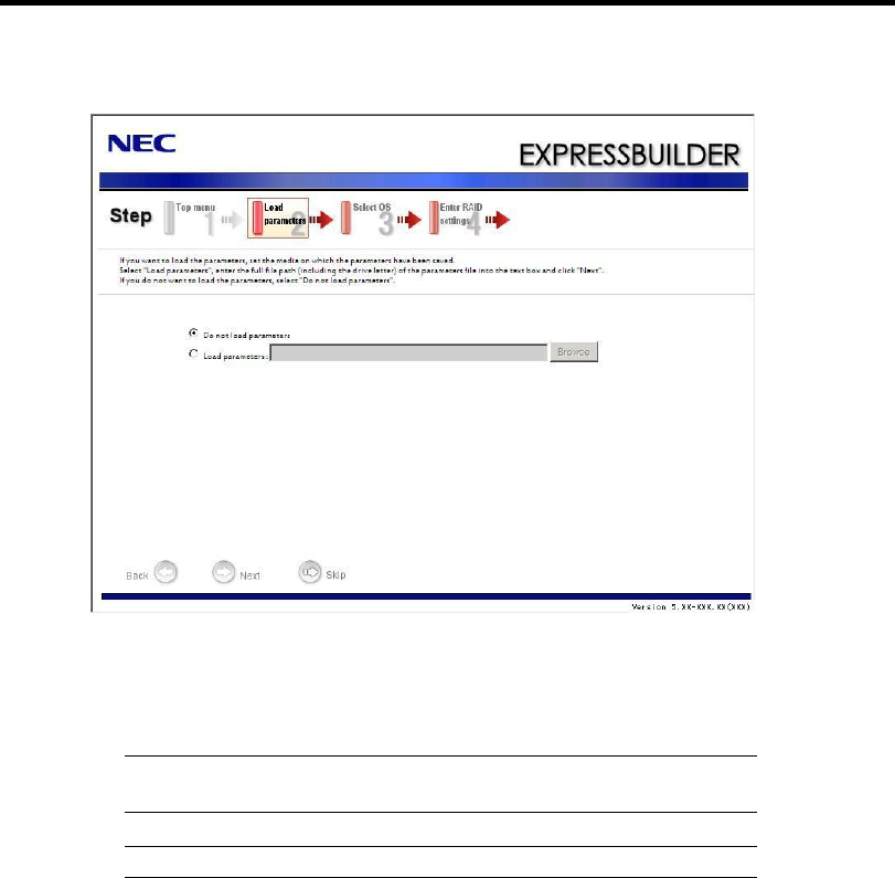
5-36 Installing the Operating System with Express Setup
7. [Load parameters] steps are displayed.
[Do not load parameters]
(1) Select [Do not load parameters].
(2) Click [Next].
IMPORTANT: The setup using a parameter file saved in the Flash
FDD is not supported.
NOTE: If a floppy disk drive is not connected, select this item.
[Load parameters]
(1) Insert the floppy disk containing the parameters file.
(2) Select [Load parameters], enter the file path of the parameters file into the text box.
(3) Click [Next].
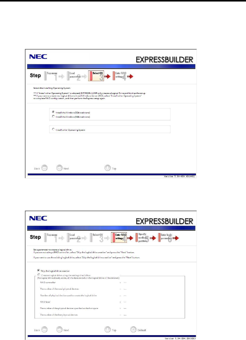
Installing the Operating System with Express Setup 5-37
8. Select the installing Operating System.
Select [Install the Windows (32bit editions)] or [Install the Windows (64bit editions)]
from the menu, click [Next].
9. Enter the setting of a logical drive.
[Enter RAID settings] steps are displayed. Confirm the parameters, modify if necessary,
and then click [Next].
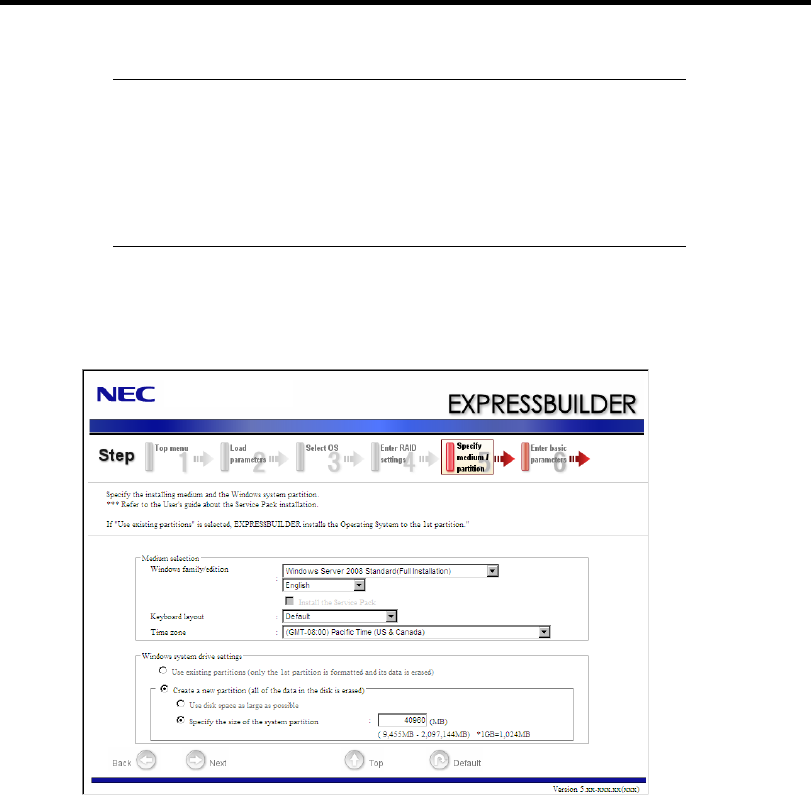
5-38 Installing the Operating System with Express Setup
NOTES:
You can use only the physical devices that have same model
number to configure logical drive.
If the process is not finished normally, the driver may not be stored
in the EXPRESSBUILDER. Refer to "Optional Board Supported
by NEC EXPRESSBUILDER" described earlier in this chapter.
10. Specify the installing medium and the Windows system partition.
[Specify medium / Partition] steps are displayed. Confirm the parameters, modify if
necessary, and then click [Next].

Installing the Operating System with Express Setup 5-39
IMPORTANT:
About partition size
– Specify the partition size larger than required minimum size for
OS installation.
– Do not specify larger partition size than the capacity of
connected hard disk drive.
– You can not specify a logical drive larger than 2,097,144MB at
RAID system.
If you select "Create a new partition" at "Windows system drive
settings", the contents of the hard disk will be all deleted.
If "Use existing partitions" is selected, EXPRESSBUILDER
installs the Operating System to the 1st partition (1st partition is
deleted). The data in the other partition is kept if the system has
two or more partitions. (See the figure below.)
First
Partition
Deleted
Second
Partition
Retained
Third
Partition
Retained
You can not re-install the system with the existing partition that is
upgraded to Dynamic Disk remained. Do not select "Use existing
partitions" at "Windows system drive settings".
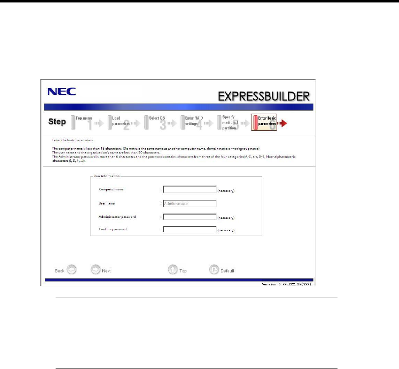
5-40 Installing the Operating System with Express Setup
11. Enter the user information.
[Enter basic parameters] steps are displayed. Confirm the parameters, modify if necessary,
and then click [Next].
IMPORTANT: Computer name and Administrator password that
satisfy the following conditions are required.
– More than 6 characters
– Contains characters from three of the following categories
(numbers, uppercase letters, lowercase letters, and signs).
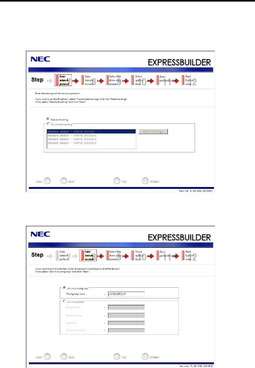
Installing the Operating System with Express Setup 5-41
12. Enter the setting of the network protocol.
[Enter Network Protocol] steps are displayed. Confirm the parameters, modify if
necessary, and then click [Next].
13. Enter the domain or workgroup name to be used.
[Enter domain account] steps are displayed. Confirm the parameters, modify if necessary,
and then click [Next].
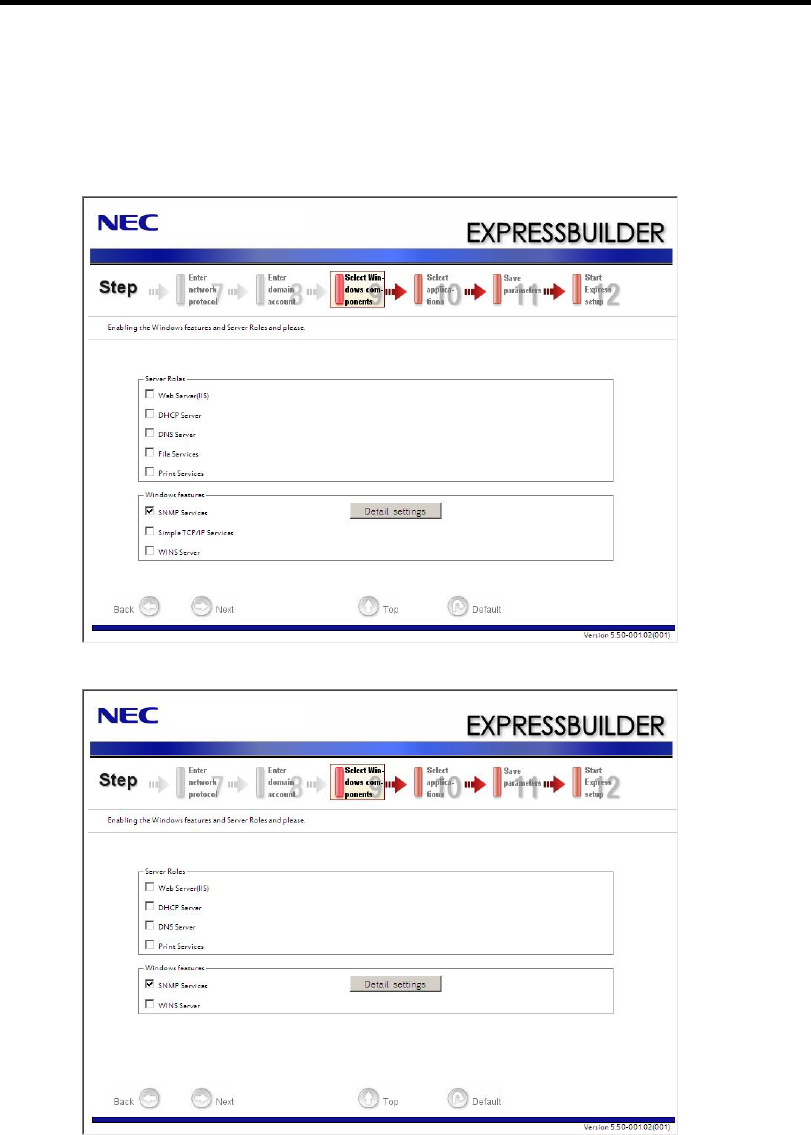
5-42 Installing the Operating System with Express Setup
14. Select the installing components.
[Select Windows components] steps are displayed. Confirm the parameters, modify if
necessary, and then click [Next].
<Full Installation>
<ServerCore Installation>
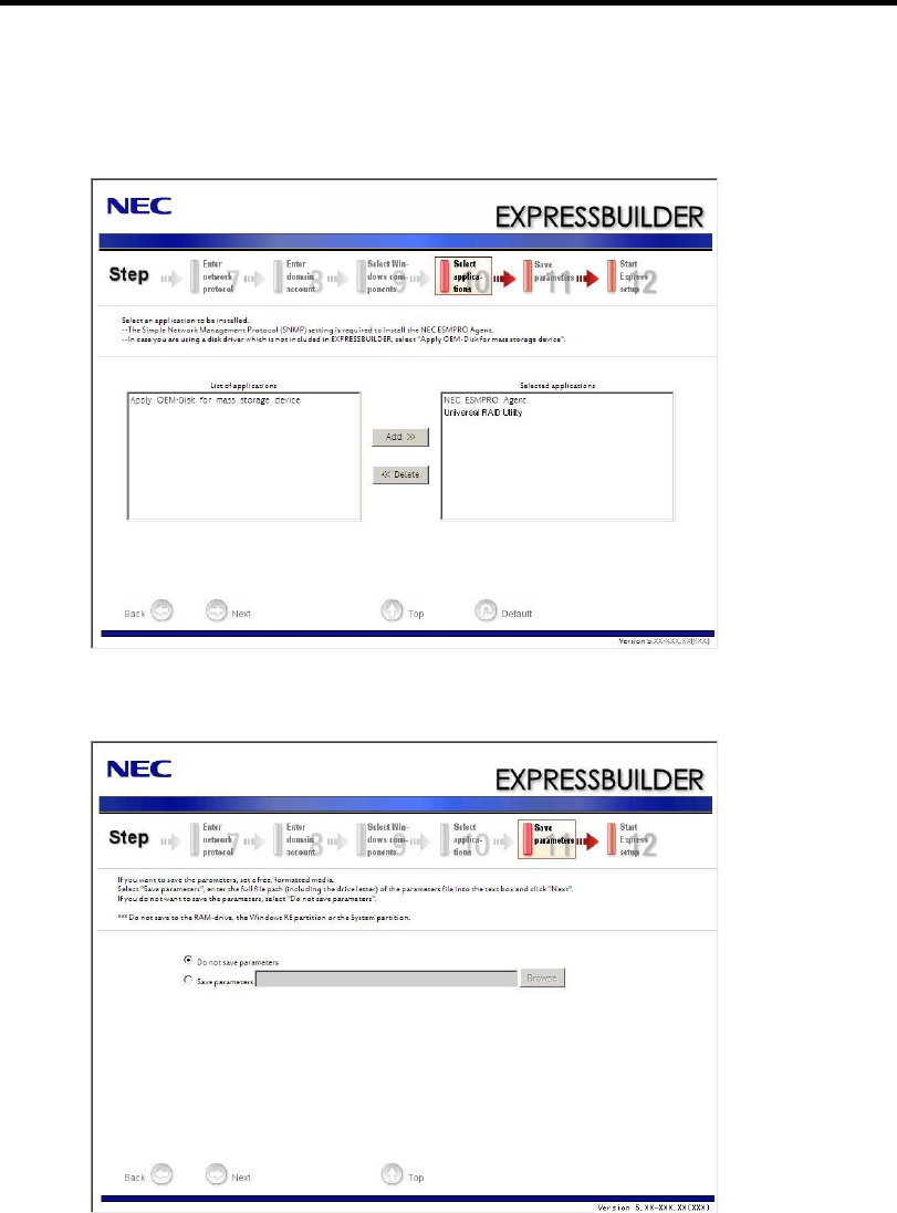
Installing the Operating System with Express Setup 5-43
15. Select the installing applications.
[Select applications] steps are displayed. Confirm the parameters, modify if necessary, and
then click [Next].
16. Save the parameters.
[Save parameters] steps are displayed.
If you want to save the parameters , set the free formatted floppy disk.
Select [Save parameters], enter the file path of the parameters files into the text box and
click [Next].
If not, select [Do not save parameters].
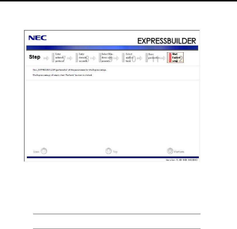
5-44 Installing the Operating System with Express Setup
17. The Express Setup will start when you click [Perform] in [Start Express setup] step.
18. Remove NEC EXPRESSBUILDER DVD from the optical disk drive according to the
message.
If you proceed the setup by using setup parameter file, remove the floppy disk from the
floppy disk drive.
19. Insert Windows Server 2008 DVD-ROM into the optical disk drive.
NOTE: Windows Server 2008 and selected applications will be
installed automatically and reboots several times.
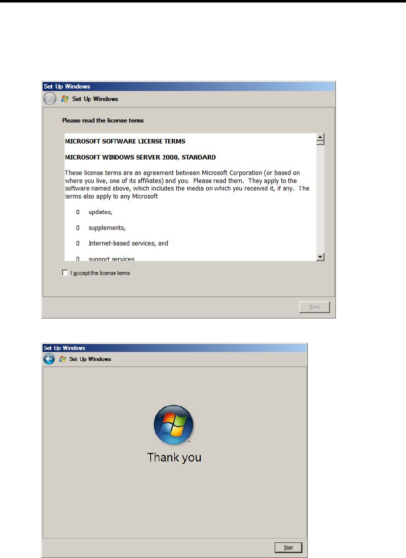
Installing the Operating System with Express Setup 5-45
20. [Agree Software License Agreement] screen appears.
Read the license terms carefully. If you agree, select I accept the license terms, and then
click [Next].
21. When the following message appears, click [Start].
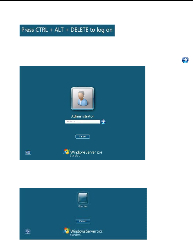
5-46 Installing the Operating System with Express Setup
22. When the following message appears, press Ctrl + Alt + Del.
23. Log on to the system.
<Full Installation>
When the following screen appears, enter your password into "Password", and click .
<Server Core Installation>
When the following screen appears, click "Other User".
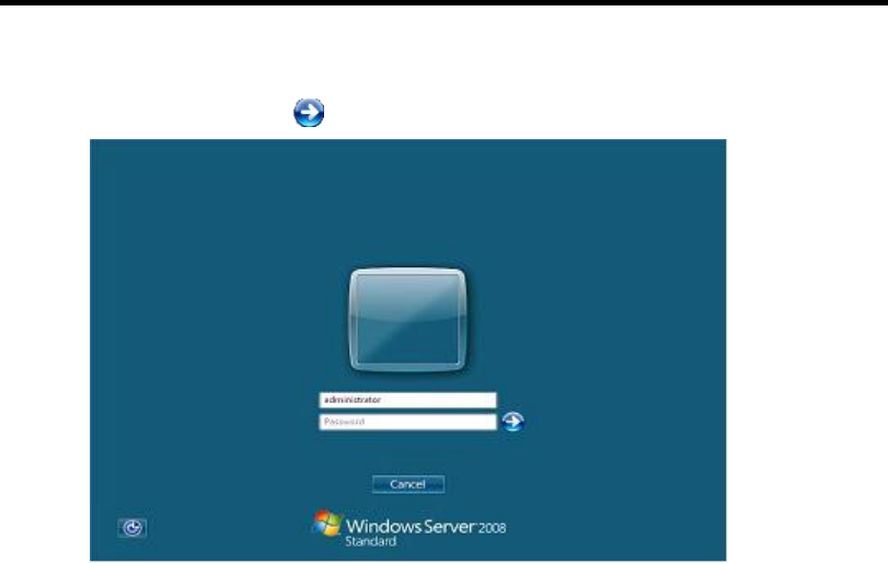
Installing the Operating System with Express Setup 5-47
In the following screen, enter "Administrator" into [UserName], your password into
"Password", and click .
Hereinafter, proceed operations according to the message.
Now the Setup using Express Setup has completed.
After Express Setup has completed, be sure to execute the tasks described in "Installing and Setting
Device Drivers".

5-48 Installing the Operating System with Express Setup
Installing and Setting Device Drivers
Follow these steps to install and configure the device drivers.
LAN Driver and PROSet
The LAN driver and PROSet have been installed automatically while your system was being
updated in the previous section.
NOTE: To change the LAN driver and PROSet settings, log on to the
system from a local console using an administrator account. Remotely
changing the settings by using the operating system’s remote desktop
feature is not supported.
Using N8104-125A Adapter after System Update
To use the N8104-125A Adapter after updating your system, you must first uninstall the LAN driver
and PROSet, and then update your system with the N8104-125A Adapter connected.
For a server running a full installation
1. Remove a team of network adapters.
NOTE: Before you remove, note down the current settings (e.g. IP
addresses) of the standard and optional adapters teamed for network
redundancy.
Configure the settings after reinstalling the LAN driver and PROSet.
To remove the team, see "Setup Team".
2. In [Control Panel], click [Uninstall Program].
3. Double-click [Intel(R) Network Connections 14.8.43.0].
[Intel(R) Network Connections (Remove Options)] appears.
4. In [Remove Options], click [Remove].
[Intel(R) Network Connections - Remove Software] appears.
5. Select [Yes].
The uninstallation starts automatically.
6. When [InstallShield Wizard Completed] appears. Click [Finish].
Restart the system.

Installing the Operating System with Express Setup 5-49
For a server running a Server Core installation
1. Note down the current settings (e.g. IP addresses) of the standard and optional adapters
teamed for network redundancy before uninstalling LAN driver.
Configure the settings after reinstalling the LAN driver.
2. At a command prompt, run dxsetup.exe in your removable medium containing the Driver
Set.
– Windows Server 2008 64-bit (x64) Editions:
<drive letter>: \015\win\winnt\ws2008x64\r148\apps\prosetdx\vistax64\dxsetup.exe
– Windows Server 2008 32-bit (x86) Editions:
<drive letter>: \015\win\winnt\ws2008\r148\apps\prosetdx\vista32\dxsetup.exe
3. In [Intel(R) Network Connections - InstallShield Wizard], click [Next].
4. Select [Remove], and click [Next].
5. Click [Remove].
Uninstallation starts automatically.
6. When [InstallShield Wizard Completed] appears, click [Finish].
Restart the system.

5-50 Installing the Operating System with Express Setup
Network Driver
Specify the details of network driver.
Two standard network drivers that are mounted will be installed automatically, but the link speed
and Duplex mode need to be specified manually.
1. Open the [Device Manager].
2. Double-click [(Network Adapter Name)] in the list.
3. Click the [Link Speed] and specify the [Speed & Duplex] value the same as the value
specified for HUB.
4. Click [OK].
5. Restart the system.
Also, add or delete any protocols and services if necessary.
You can operate the process on the property dialog box for local area network which can be
appeared from [Network and Dial-up Connection].
NOTE: We recommend you to add [Network Monitor] at [Adding
Services].
[Network Monitor] can monitor the frame (or the packet) that the
computer installing [Network Monitor] sends or receives. This tool is
valuable when analyzing network trouble. For information on how to
install the tool, see the "Setting for Solving Problems" described later
in this chapter.
Optional Network Board Driver (N8104-112/119/120/121/125A/126)
The following optional network boards are available for the N8104-112/119/120/121/125A/126.
To use the N8104-125A Adapter, see" Using N8104-125A Adapter after System Update" in Pages
5-48 to 5-49.
The drivers for other network boards are automatically installed by Windows Plug-and-Play. You do
not need to install them manually.

Installing the Operating System with Express Setup 5-51
Setup Team
Adapter Fault Tolerance (AFT) is a feature that creates a group containing more than one adapter
and automatically converts the process of the working adapter to the other adapter in the group
when any trouble occurred on that adapter.
Adaptive Load Balancing (ALB) is a feature that creates a group containing more than one adapter
and enhances the throughput by operating packet transmission from the server by all the adapters.
This feature includes AFT feature.
Switch Fault Tolerance (SFT) is a feature that provides a failover relationship between two ports
when each port is connected to a separate switch.
SFT supports two ports per team.
Static Link Aggregation (SLA) accounts for the GEC and 802.3ad static protocols.
SLA is a switch-assisted teaming mode and requires configuring ports at both ends of the link:
server interfaces and switch ports.
IMPORTANT:
AFT/ALB setup must be operated after system update and
restarting the system.
All the adapters specified as a group of Adapter Teaming must
exist on the same LAN. If they are connected to the separate
switches, they will not work normally.
The adapters specified as a group of Adaptive Load Balancing
(ALB) can be connected to only Switching Hub.
When exchange the mother board or option network card, make
sure to remove the adapter team before exchanges and recreate the
adapter team after exchange complete.
Confirm the port setting of switching hub (L2) matches the server
network adapter Teaming mode.
Teaming is not supported with Windows Server Core.
Create Team
1. Open the [Device Manager].
2. Open [Network adapters] → [Intel(R) xxx] properties.
3. Click [Teaming] tab and check the [Team this adapter with other adapters] check box.
Click [New Team].
4. Fill the name of the team in [Specify a name for the team] and click [Next].
5. Include the adapter to the team and click [Next].

5-52 Installing the Operating System with Express Setup
6. Select a team mode, and then click [Next].
IMPORTANT: Following team types are supported.
Adapter Fault Tolerance
Adaptive Load Balancing
Static Link Aggregation
Switch Fault Tolerance
7. Click [Finish].
8. Click [TEAM: "Team name"] from [Device manager] → [Network adapters] to modify
the team.
Click [Settings] tab and click [Modify Team] button.
9. Refer to the following procedure to set the team member adapter priority status.
– Set Primary
Point the adapter and click [Set Primary] button.
– Set Secondary
Point the adapter and click [Set Secondary] button.
NOTE: Adapter priority config can be confirmed by the following
procedure:
1. Click [TEAM: "Team name"] from [Device manager]→[Network
adapters].
2. Click [Settings] and confirm Adapters in team list.
10. Click [Test Switch] → [Run test] to confirm the adapter team is properly setup.
Confirm the result in [Test results]
11. Restart the system.
Remove Team
1. Open the [Device Manager].
2. Click [Network adapters], and open [TEAM: "Team name"] properties.
3. Click [Setting] tab.
4. Click [Remove Team] button.
5. Click [Yes] to the message.
6. Confirm [TEAM: "Team name"] adapter in not existing in [Network adapters] tree and
reboot the system.

Installing the Operating System with Express Setup 5-53
Setting WOL
Refer to the following procedure to enable WOL.
1. Start Device Manager.
2. Point to [Network adapters] and double click [Intel(R) 82547L Gigabit Network
Connection] to open the adapter [Properties].
3. Click [Power Management] tab and change setting in [Wake On LAN] according to the
following list.
Setting item Change setting
"Wake On Directed Packet" ON or OFF
"Wake On Magic Packet" ON
"Wake on Magic Packet from power off state" ON
"Wake on Link" OFF
IMPORTANT: DirectedPacket(*1) will not wake up the system on
Shutdown state even “Wake On Directed Packet” is setting “ON”.
Only on Sleep or Hibernate state will wake up by a DirectedPacket.
(*1) Packet with the Ethernet address of the adapter in ethernet header
or Packet with an IP address assigned to the adapter in IP header.
NOTES:
[Power Saver Options] setting is not necessary to change.
Above setting will be maintained until manually resetting are
executed.
IMPORTANT: The parameters of [Wake On LAN] will not exist, if
the network ports are not available for WOL.
4. Click [OK].
5. Restart the system.

5-54 Installing the Operating System with Express Setup
Graphics Accelerator Driver
If you use standard graphics accelerator drivers, update your system with NEC
EXPRESSBUILDER DVD attached to your system.
Standard graphics accelerator drivers will be installed automatically.
Refer to "Graphics Accelerator Driver" described in Appendix E-29 when you want to reinstall the
driver individually.
Installing SCSI Controller Driver (N8103-75/95/107)
If you use the SCSI Controller N8103-75/95/107, you do not need to install the driver manually. It is
automatically installed by Windows Plug-and-Play.
Installing SAS Controller Driver (N8103-104A)
If you use the SAS Controller N8103-104A, you do not need to install the driver manually. It is
automatically installed by Windows Plug-and-Play.
Setting for Solving Problems
Setup your computer in advance so that it can recover from any trouble precisely and as soon as
possible when it should occur.
For more information, refer to Page 5-80.

Installing the Operating System with Express Setup 5-55
Windows Server 2003
This section explains how to install Microsoft® Windows Server® 2003 by using the Express
Setup.
NOTES:
Express Setup does not support the installation of Windows Server
2003 x64 Editions. If you want to install it, see Appendix F.
If you install Windows Server 2003 without using Express Setup,
see Appendix G.
Notes on Windows Installation
This section explains the notes on the Windows installation.
Confirm these notes before starting the Express Setup.
About the Windows family
This computer supports the following Windows editions:
Microsoft® Windows Server® 2003 R2 Standard Edition (hereinafter, referred to as
"Windows Server 2003")
NOTE: Express Setup does not support the installation of Windows
Server 2003 x64 Editions. If you want to install it, see Appendix F.
On installing other OS, contact sales dealer or the maintenance service representative.
BIOS Settings
Confirm the BIOS settings described in Chapter 4 before installing Windows Server 2003.

5-56 Installing the Operating System with Express Setup
Service Pack Which EXPRESSBUILDER Supports
The NEC EXPRESSBUILDER DVD attached to the server supports following combination of the
OS installation media and Service Pack.
Windows Server 2003 R2 x64 Edition
– OS installation media (with Service Pack 2)
– OS installation media (No Service Pack) + Service Pack 2
– OS installation media (No Service Pack)
Windows Server 2003 R2
– OS installation media (with Service Pack 2)
– OS installation media (No Service Pack) + Service Pack 2
– OS installation media (No Service Pack)
Supported Mass Storage Controllers
The NEC EXPRESSBUILDER DVD attached to your system supports the following mass storage
controllers for installation.
NOTE: If you want to install the other boards by using a driver floppy
disk ("OEM-Disk for Mass storage device"), except ones listed below,
see "Installing with the OEM-Disk for Mass storage device" and
"Installing Optional Mass Storage Driver" of "Parameter File Creator"
in Chapter 6.
Controllers supporting installation of OS with Express Setup
– N8103-109 RAID Controller (128 MB, RAID0/1/5/6)*
– N8103-116A RAID Controller (128 MB, RAID0/1)*
– N8103-117A RAID Controller (128 MB, RAID0/1/5/6)*
– Onboard RAID Controller (LSI Embedded MegaRAID™)
Other controllers
– N8103-75 SCSI Controller*
– N8103-95 SCSI Controller*
– N8103-104A SAS Controller*
– N8103-107 SCSI Controller*
* Option
NOTES:
The driver of option card mentioned above is stored in the NEC
EXPRESSBUILDER DVD.
If you use the board not mentioned above, the ExpressSetup will
fail. Refer to the instructions attached to the board.

Installing the Operating System with Express Setup 5-57
About the Hardware Components
When you install the Windows Server 2003, Express Setup requires several preparations if this
computer uses the following hardware components.
Installing on the Mirrored Volume
If you want to install the Windows Server 2003 on the volume that is mirrored using "Disk
Management", invalidate the mirroring and set back to the basic disk before the installation, and
validate the mirroring again after the installation.
You can create, invalidate or delete the mirror volume by using "Disk Management" in "Computer
Management".
Mounting MO Device
Do not mount an MO device on this computer during the Windows installation.
About Removable Media
Do not set removable media, such as DAT and LTO, into the device mounted on this computer
during the Windows installation.
Connecting Hard Disk Drive
Do not connect the other hard disk drives except the drive that you want to create the Windows
system drive.
If you create multiple logical drives in your system, see "Re-installing the Operation System if
Multiple Logical Drives Exist" (5-92).
Re-installing to the hard disk drive which has been upgraded to Dynamic
Disk
You cannot re-install Windows Server 2003 with the current partition of the hard disk drive
upgraded to Dynamic Disk kept remained.
If you want to keep the current partition remained, see Appendix G to re-install the system.
Peripheral Devices such as RDX
Depending on your hardware configuration, some peripheral devices need to be removed or
disabled before starting setup. Refer to the instruction manual which came with the peripheral
device for pertinent information, and proceed accordingly.

5-58 Installing the Operating System with Express Setup
About the System Partition Size
The system partition size can be calculated from the following formula.
Size necessary to install the system + Paging File Size + Dump File Size
+ Application Size
Size necessary to install the system = 3500MB (Windows Server 2003 R2)
= 3500MB (Windows Server 2003 R2 with Service
Pack 2)
= 5300MB (Windows Server 2003 R2 + Service Pack
2 CD-ROM)
Paging File Size (Recommended) = Mounted Memory Size * 1.5
Dump File Size = Mounted Memory Size + 12MB
Application Size = Required Size
IMPORTANT:
The above-mentioned paging file size is recommended for
collecting debug information (memory dump). The paging file
with initial size large enough to store the dump file in the boot
drive is required.
Correct debug information might not be able to be collected due to
virtual memory shortage when the paging file is insufficient, so set
an enough size of the paging file with the entire system.
The maximum paging file size which can be set on one partition is
4095MB. If the above paging file size exceeds 4095MB, specify
4095MB for the paging file size.
The maximum dump file size for the system with more than 2GB
memory mounted is '2048MB + 12MB'.
If you install any application program or the like, add necessary
space to the partition to install these programs.
For example, if the mounted memory size is 1GB (1,024MB), the partition size will be calculated by
the above formula as follows:
3,500MB + (1,024MB * 1.5) + (1,024MB + 12MB) + Application Size
= 6,072MB + Application Size

Installing the Operating System with Express Setup 5-59
Dividing into the partition of the recommended size into multiple disks as written below will solve
problem that it cannot be reserved in one disk.
1. Set the "Size required for installation + Paging file size".
2. See Chapter 5 and set that debugging information (equivalent to the dump file size) is to
be written to a separate disk.
(If the disk does not have enough free space to enable the dump file size to be written,
then after installing the system using the "Size required for installation + Paging file size",
install an additional new disk.)
Installing the Service Pack
When installing Windows Server 2003 R2, it is not necessary to install the Service Pack 1.
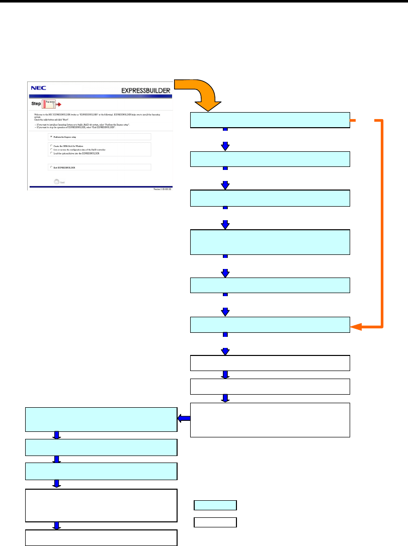
5-60 Installing the Operating System with Express Setup
FLOW OF SETUP
This section visually describes the flow of the setup operated by Express Setup.
Loading parameters (Step 2)
Select the operating system (Step 3)
Next
RAID configuration (Step 4)
Next
Windows Confirm Setting / Input
(Steps 5 to 10)
Next
Save parameters (Step 11)
Next
Start Express Setup (Step 12)
Next
RAID Configuration
Perform
Create the OS partition / format
Copying Windows driver
↓
Copying Selected Application
Remove the Floppy Disk and CD/DVD-ROM
from the Drive
Insert Windows CD-ROM
Agree Software License Agreement
Install OS Automatically
↓
Log on Automatically
The installation is completed.
: Process that needs to input or select
: Process that proceeds automatically
Skip
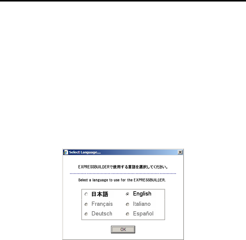
Installing the Operating System with Express Setup 5-61
INSTALLING Windows Server 2003
Express Setup proceeds the setup by selecting or inputting several parameters on the wizard. You
can also save the parameters to a floppy disk as a parameters file.
1. Turn the power of peripheral device on, and then turn on the server.
2. Insert the NEC EXPRESSBUILDER DVD into the optical disk drive of the server.
3. Press the RESET switch or press Ctrl, Alt, and Delete to reboot from the NEC
EXPRESSBUILDER. (You may also turn off and then on again to reboot the server.)
The system will boot from the DVD-ROM and NEC EXPRESSBUILDER starts.
Select "Os installation *** default ***" from the Boot selection menu. (If you do not hit
any key, "Os installation" is selected automatically.)
The Top menu will appear.
4. Select [English] from the [Select Language], click [OK].
5. When the Software License Agreement screen of Windows PE appears, click [Yes].
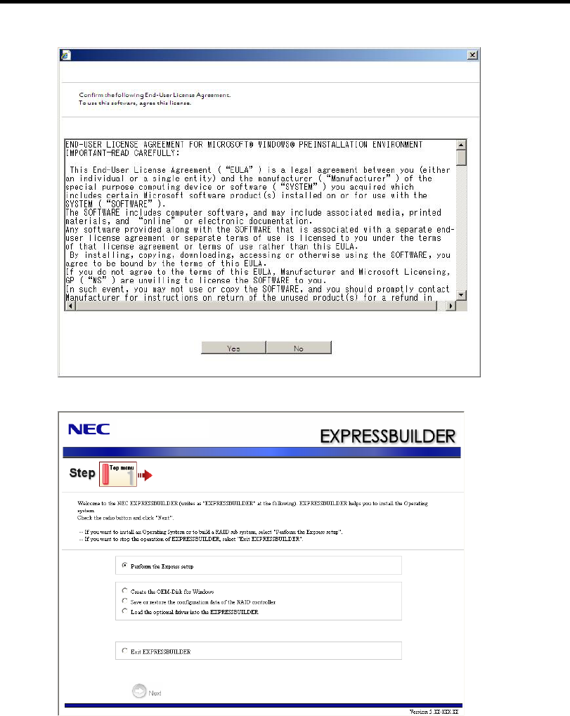
5-62 Installing the Operating System with Express Setup
6. Select [Perform the Express setup] from the Top Menu, click [Next].
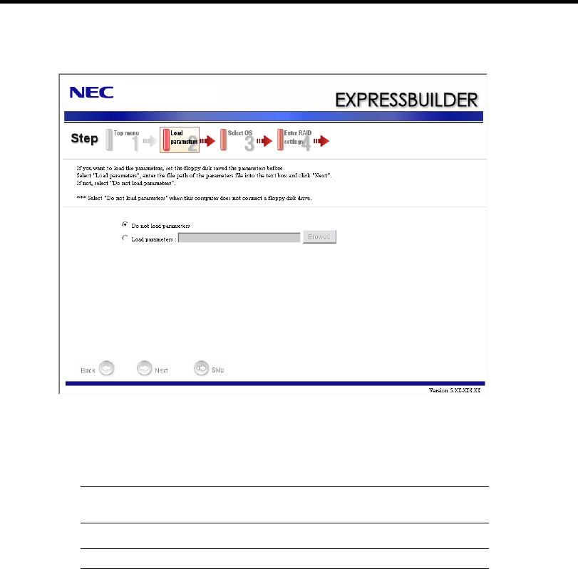
Installing the Operating System with Express Setup 5-63
7. [Load parameters] steps are displayed.
[Do not load parameters]
(1) Select [Do not load parameters].
(2) Click [Next].
IMPORTANT: The setup using a parameter file saved in the Flash
FDD is not supported.
NOTE: If a floppy disk drive is not connected, select this item.
[Load parameters]
(1) Insert the floppy disk containing the parameters file.
(2) Select [Load parameters], enter the file path of the parameters file into the text box.
(3) Click [Next].
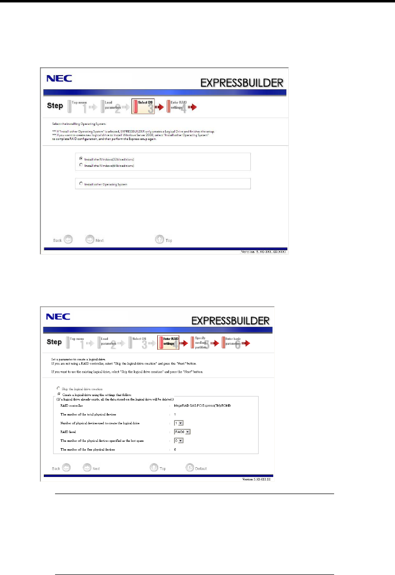
5-64 Installing the Operating System with Express Setup
8. Select the installing Operating System.
Select [Install the Windows (32bit editions)] from the menu, click [Next].
9. Enter the setting of a logical drive.
[Enter RAID settings] steps are displayed. Confirm the parameters, modify if necessary,
and then click [Next].
NOTES:
You can use only the physical devices that have same model
number to configure logical drive.
If the process is not finished normally, the driver may not be stored
in the EXPRESSBUILDER. Refer to "Optional Board Supported
by NEC EXPRESSBUILDER" described earlier in this chapter.
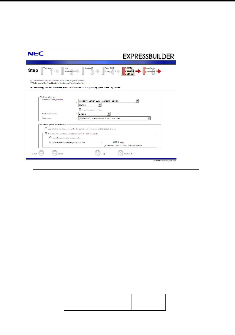
Installing the Operating System with Express Setup 5-65
10. Specify the installing medium and the Windows system partition.
[Specify medium / Partition] steps are displayed. Confirm the parameters, modify if
necessary, and then click [Next].
IMPORTANT:
If you install Windows Server 2003 R2 and Service Pack, apply
Windows Server 2003 R2 DISC 2 after Express Setup completion,
and then install Service Pack by "Updating the system".
About partition size
– Specify the partition size larger than required minimum size for
OS installation.
– Do not specify larger partition size than the capacity of
connected hard disk drive.
– You can not specify a logical drive larger than 2,097,144MB at
RAID system.
If you select "Create a new partition" at "Windows system drive
settings", the contents of the hard disk will be all deleted.
If "Use existing partitions" is selected, EXPRESSBUILDER
installs the Operating System to the 1st partition (1st partition is
deleted). The data in the other partition is kept if the system has
two or more partitions. (See the figure below.)
First
Partition
Deleted
Second
Partition
Retained
Third
Partition
Retained
You can not re-install the system with the existing partition that is
upgraded to Dynamic Disk remained. Do not select "Use existing
partitions" at "Windows system drive settings".
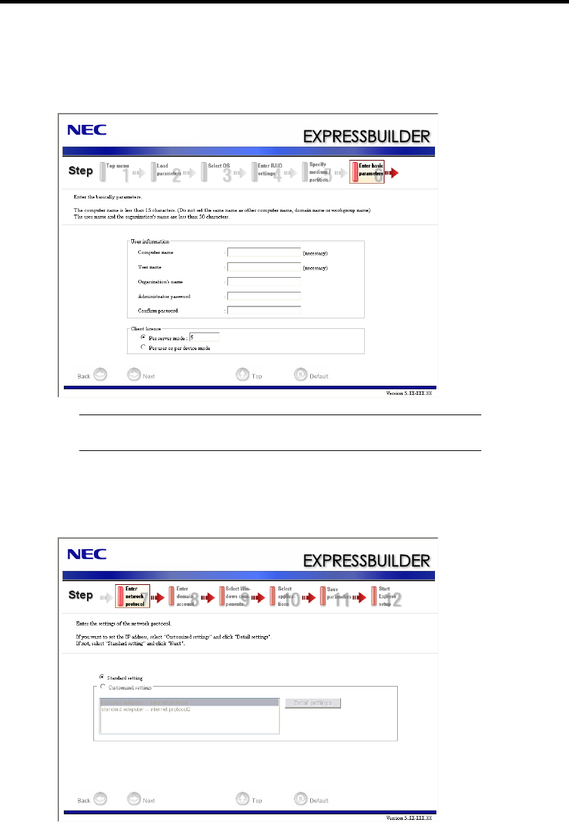
5-66 Installing the Operating System with Express Setup
11. Enter the user information and client license mode.
[Enter basic parameters] steps are displayed. Confirm the parameters, modify if necessary,
and then click [Next].
NOTE: Even if you do not input value into "Administrator password",
"Confirm password", "zzzzz" is displayed.
12. Enter the setting of the network protocol.
[Enter Network Protocol] steps are displayed. Confirm the parameters, modify if
necessary, and then click [Next].
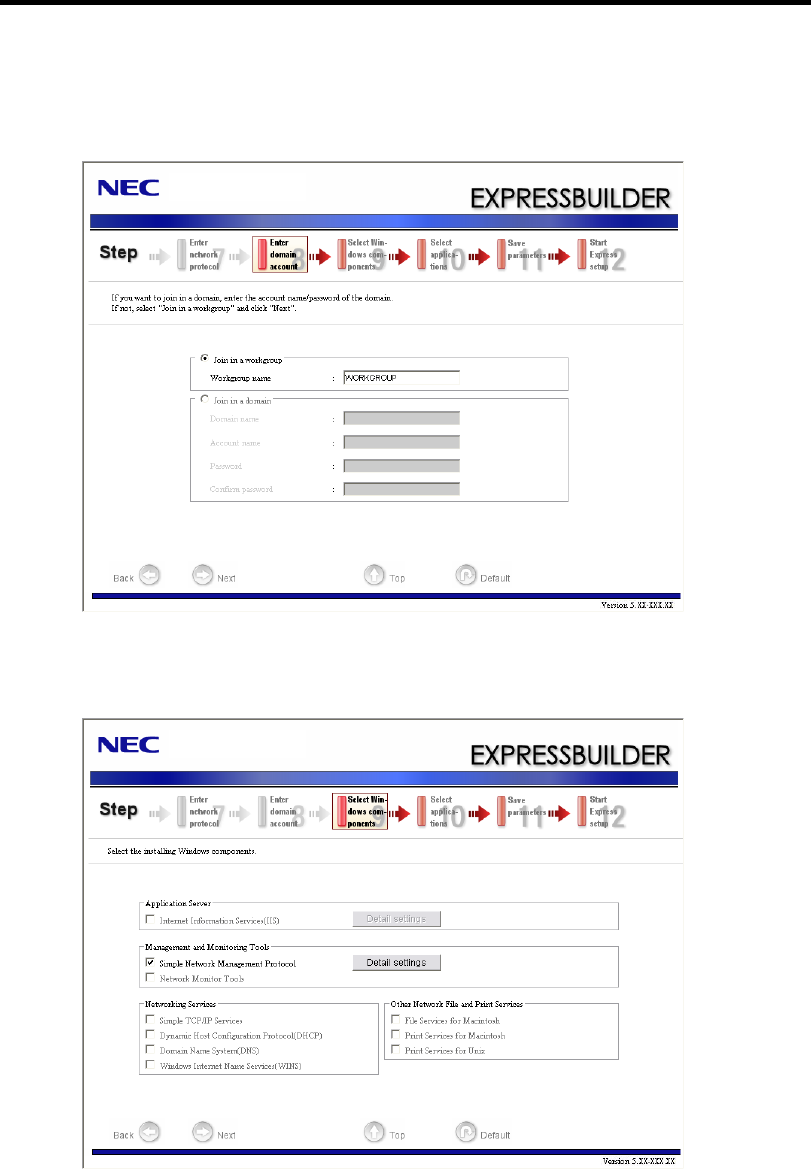
Installing the Operating System with Express Setup 5-67
13. Enter the domain or workgroup name to be used.
[Enter domain account] steps are displayed. Confirm the parameters, modify if necessary,
and then click [Next].
14. Select the installing components.
[Select Windows components] steps are displayed. Confirm the parameters, modify if
necessary, and then click [Next].
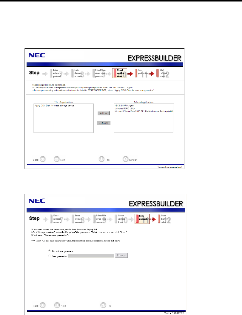
5-68 Installing the Operating System with Express Setup
15. Select the installing applications.
[Select applications] steps are displayed. Confirm the parameters, modify if necessary, and
then click [Next].
16. Save the parameters.
[Save parameters] steps are displayed.
If you want to save the parameters , set the free formatted floppy disk.
Select [Save parameters], enter the file path of the parameters files into the text box and
click [Next].
If not, select [Do not save parameters].
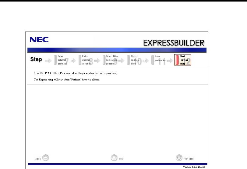
Installing the Operating System with Express Setup 5-69
17. The Express Setup will start when you click [Perform] in [Start Express setup] step.
18. Remove NEC EXPRESSBUILDER DVD from the optical disk drive according to the
message.
If you proceed the setup by using setup parameter file, remove the floppy disk from the
floppy disk drive.
Insert Windows Server 2003 CD-ROM into the optical disk drive.
[Agree Software License Agreement] screen appears.

5-70 Installing the Operating System with Express Setup
19. Read the contents carefully and click [Yes] if you do agree. If you do not agree, click
[No].
IMPORTANT:
If you do not agree to this agreement, the setup terminates and
Windows Server 2003 will not be installed.
If "NetWare Gateway (and Client) Service" is specified to install,
the window to specify the details of "NetWare Gateway (and
Client) Service" pops up on the first logon. Specify the appropriate
value.
When the following message is displayed, click [OK] and input the
product key.
T
he setup script file does not contain a valid Product ID.
Contact your system administrator for a valid Product ID.
20. Insert Microsoft Windows Server 2003 R2 DISC 2 into the optical disk drive after the OS
installation.
Hereinafter, proceed operations according to the message.
When the installation has finished, remove Microsoft Windows Server 2003 R2 DISC 2 from the
optical disk drive, and restart the system.
Now the Setup using Express Setup has completed.

Installing the Operating System with Express Setup 5-71
INSTALLING AND SETTING DEVICE DRIVERS
Follow these steps to install and configure the device drivers.
PROSet
NOTE: All of the operation that related to Intel® PROSet must be
executed by administrator privileges. Operation by [Remote Desktop
Connection] is prohibited.
Without changing any parameter when opened the properties of
adapter teaming, click the [Cancel] button for close the dialog.
Click [OK] button will cause temporary loss of network connectivity.
PROSet is a utility that confirms the function of network contained in network driver.
Utilizing PROSet enables the following items:
Confirm detailed information of the adapter.
Diagnose loop back test, packet transmission test and so on.
Setup of teaming.
Configuring several network adapters as one team provides the server a tolerant environment on any
trouble and enhances throughput between the switches.
PROSet is necessary to utilize these features.
Follow the procedure below to install PROSet.
1. Insert the NEC EXPRESSBUILDER DVD into the optical disk drive.
If the autorun menu is displayed, close menu screen.
2. The [Windows Explorer] dialog starts.
* The procedure in the case of the standard start menu
Click Start menu and click [Windows Explorer].
* The procedure in the case of the classic start menu
Click Start menu, point to [Programs], [Accessories] and click [Windows Explorer].
3. Run "dxsetup.exe" in the following directory.
\015\win\winnt\dotnet\r148\apps\prosetdx\win32
The [Intel(R) PROSet - InstallShield Wizard] dialog starts.
4. Click [Next].
5. Choose "I accept the terms in the license agreement" and click [Next].

5-72 Installing the Operating System with Express Setup
6. Click [Next].
7. Click [Install].
8. When [InstallShield Wizard Completed] window is displayed, click [Finished].
9. Remove the NEC EXPRESSBUILDER DVD from the optical disk drive, restart the
system.

Installing the Operating System with Express Setup 5-73
Network Driver
Specify the details of network driver.
One standard network driver that is mounted will be installed automatically, but the link speed and
Duplex mode need to be specified manually.
When PROSet is not installed
1. Open the [Device Manager]
2. Double-click [(Network Adapter Name)] in the list.
3. Click the [Advanced] and specify the [Link Speed & Duplex] value the same as the value
specified for HUB.
4. Click [OK].
5. Restart the system.
When PROSet is installed
1. Open the [Device Manager]
2. Double-click [(Network Adapter Name)] in the list.
3. Click the [Link Speed] and specify the [Speed & Duplex] value the same as the value
specified for HUB.
4. Click [OK].
5. Restart the system.
Also, add or delete any protocols and services if necessary.
You can operate the process on the property dialog box for local area network which can be
appeared from [Network and Dial-up Connection].
NOTE: It is recommend to add [Network Monitor] at [Adding
Services]. [Network Monitor] can monitor the frame (or the packet)
that the computer installing [Network Monitor] sends or receives. This
tool is valuable when analyzing network trouble. For information on
how to install the tool, see the "Setting for Solving Problems"
described later in this chapter.

5-74 Installing the Operating System with Express Setup
Optional Network Board Driver
If you want to use optional Network Board (N8104-111/112/119/120/121/125A/126/123A), the
network driver will be installed automatically. Therefore, the driver attached to the Network board
should not be used.
If you want to use optional Network Board (N8104-111/112/119/120/121/125A/126/123A), install
the driver stored in NEC EXPRESSBUILDER DVD.
In case of using (N8104-111)
"\015\win\winnt\dotnet\r148\pro100\win32\ndis5x"
In case of using (N8104-112/119/120/121/125A/126)
"\015\win\winnt\dotnet\r148\pro1000\win32\ndis5x"
If the procedure of installation is not clear, refer to the installation procedure described in the
section "Installation of the Optional Network Board Driver".
In case of using (N8104-123A)
Please refer to the installation manual provided with the board.
Installation of the Optional Network Board Driver
1. Start Device Manager.
2. Click [Network adapters] and double-click [(Network Adapter Name)].
[(Network Adapter Name) Properties] appears.
NOTE: [(Intel(R) PRO/1000...)] is the name of On-Board adapter. All
other names show the Optional Network Board.
3. Click [Driver] tab and click [Update Driver...]. [Hardware Update Wizard] appears.
4. Select the [Install from a list or specific location (Advanced)] radio button and click
[Next].
5. Select the [Search for the best driver in these locations] radio button and uncheck the
[Search removable media (floppy, CD-ROM...)] check box.
6. Check the [Include this location in the search] check box and when using [(N8104-111)],
specify
[\015\win\winnt\dotnet\r148\pro100\win32\ndis5x].
Then click [Next].
When using [(N8104-112/119/120/121/125A/126)], specify
[\015\win\winnt\dotnet\r148\pro1000\win32\ndis5x].
Then click [Next].
7. Click [Finish].
8. Restart the system.

Installing the Operating System with Express Setup 5-75
Setup Team
Adapter Fault Tolerance (AFT) is a feature that creates a group containing more than one adapter
and automatically converts the process of the working adapter to the other adapter in the group
when any trouble occurred on that adapter.
Adaptive Load Balancing (ALB) is a feature that creates a group containing more than one adapter
and enhances the throughput by operating packet transmission from the server by all the adapters.
This feature includes AFT feature.
Switch Fault Tolerance (SFT) is a feature that provides a failover relationship between two ports
when each port is connected to a separate switch.
SFT supports two ports per team.
Static Link Aggregation (SLA) accounts for the GEC and 802.3ad static protocols.
SLA is a switch-assisted teaming mode and requires configuring ports at both ends of the link:
server interfaces and switch ports.
IMPORTANT:
AFT/ALB setup must be operated after installing the
drivers/PROSet and restarting the system.
All the adapters specified as a group of Adapter Teaming must
exist on the same LAN. If they are connected to the separate
switches, they will not work normally.
The adapters specified as a group of Adaptive Load Balancing
(ALB) can be connected to only Switching Hub.
When exchange the mother board or option network card, make
sure to remove the adapter team before exchanges and recreate the
adapter team after exchange complete.
Confirm the port setting of switching hub (L2) matches the server
network adapter Teaming mode.
Create Team
1. Open the [Device Manager].
2. Open [Network adapters] → [Intel(R) xxx] properties.
3. Click [Teaming] tab and check the [Team this adapter with other adapters] check box.
Click [New Team].
4. Fill the name of the team in [Specify a name for the team] and click [Next].
5. Include the adapter to the team and click [Next].

5-76 Installing the Operating System with Express Setup
6. Select a team mode, and then click [Next].
IMPORTANT: Following team types are supported.
Adapter Fault Tolerance
Adaptive Load Balancing
Static Link Aggregation
Switch Fault Tolerance
7. Click [Finish].
8. Click [TEAM: "Team name"] from [Device manager] → [Network adapters] to modify
the team. Click [Settings] tab and click [Modify Team] button.
9. Refer to the following procedure to set the team member adapter priority status.
– Set Primary
Point the adapter and click [Set Primary] button.
– Set Secondary
Point the adapter and click [Set Secondary] button.
NOTE: Adapter priority config can be confirmed by the following
procedure:
1. Click [TEAM: "Team name"] from [Device manager] → [Network
adapters].
2. Click [Settings] and confirm Adapters in team list.
10. Click [Test Switch] → [Run test] to confirm the adapter team is properly setup.
Confirm the result in [Test results]
11. Restart the system.
Remove Team
1. Open the [Device Manager].
2. Click [Network adapters], and open [TEAM: "Team name"] properties.
3. Click [Setting] tab.
4. Click [Remove Team] button.
5. Click [Yes] to the message.
6. Confirm [TEAM: "Team name"] adapter in not existing in [Network adapters] tree and
reboot the system.

Installing the Operating System with Express Setup 5-77
Setting WOL
Refer to the following procedure to enable WOL.
When PROSet is not installed
1. Start Device Manager.
2. Point to [Network adapters] and double click [Intel(R) 82547L Gigabit Network
Connection] to open the adapter [Properties].
3. Click [Power Management] tab and change setting in [Wake On LAN] according to the
following list.
Setting item Change setting
"Allow the computer to turn off this device to save power" ON
"Allow this device to bring the computer out of standby" ON or OFF
IMPORTANT:
■ Set "Allow this device to bring..." to "ON", WOL by
DirectedPacket(*1) or MagicPacket will be available on Standby
state.
■ WOL by DirectedPacket is not available on Hibernate and
Shutdown state.
(*1) Packet with the Ethernet address of the adapter in ethernet header
or Packet with an IP address assigned to the adapter in IP header.
4. Click [Advanced] tab and point to [Enable PME].
5. Set the "Enable" in [Value].
6. Click [OK].
7. Restart the system.

5-78 Installing the Operating System with Express Setup
When PROSet is installed
1. Start Device Manager.
2. Point to [Network adapters] and double click [Intel(R) 82547L Gigabit Network
Connection] to open the adapter [Properties].
3. Click [Power Management] tab and change setting in [Wake On LAN] according to the
following list.
Setting item Change setting
"Wake On Directed Packet" ON or OFF
"Wake On Magic Packet" ON
"Wake on Magic Packet from power off state" ON
"Wake on Link" OFF
IMPORTANT: DirectedPacket(*1) will not wake up the system on
Shutdown state even “Wake On Directed Packet” is setting to “ON”.
Only on Sleep or Hibernate state will wake up by a DirectedPacket.
NOTES:
[Power Saver Options] setting is not necessary to change.
Above setting will be maintained until manually resetting are
executed.
IMPORTANT: The parameters of [Wake On LAN] will not exist, if
the network ports are not available for WOL.
4. Click [OK].
5. Restart the system.

Installing the Operating System with Express Setup 5-79
Graphics Accelerator Driver
If you use standard graphics accelerator drivers, update your system with NEC
EXPRESSBUILDER DVD attached to your system.
Standard graphics accelerator drivers will be installed automatically.
Refer to "Graphics Accelerator Driver" described in Appendix G-22 when you want to reinstall the
driver individually.
Installing SCSI Controller Driver (N8103-75/95/107)
If you use the SCSI Controller N8103-75/95/107, update your system with NEC
EXPRESSBUILDER DVD attached to your system.
The SCSI Controller driver will be installed automatically.
Installing SAS Controller Driver (N8103-104A)
If you use the SAS Controller N8103-104A, update your system with NEC EXPRESSBUILDER
DVD attached to your system.
The SAS Controller driver will be installed automatically.
Setting for Solving Problems
Setup your computer in advance so that it can recover from any trouble precisely and as soon as
possible when it should occur.
For more information, refer to Page 5-80.

5-80 Installing the Operating System with Express Setup
SETTING FOR SOLVING PROBLEMS
Setup the following issue in advance so that your computer can recover from any trouble precisely
and as soon as possible when it should occur.
Memory Dump (Debug Information)
This section describes the procedures for collecting memory dump (debug information) in the
server.
IMPORTANT: Cautions for the Memory Dump
The staff of maintenance service representative is in charge of
collecting memory dump. Customers need only to specify the
memory dump.
If any trouble occur after specifying the process below, the
message to inform that the system is in short of virtual memory
may appear, but continue to start the system. If you restart the
system in such case, memory dump may not be stored correctly.
When the system is Windows Server 2008 R2
Follow the procedure below to specify.
1. Click Start and select [Control Panel].
The [Control Panel] window appears.
2. Click [System and Security] and then select [System].
NOTE: If [View by] is not set as [Category], start [System] from
Control Panel directly.
3. Click [Advanced system settings].
The [System Properties] dialog box appears.
4. Select [Advanced] tab.
5. Click [Settings] on the [Startup and Recovery] group box.
6. Modify [Dump file] in the [Write debugging information] group box, and click [OK].
e.g. Write the debug information in D drive with the file name
"MEMORY.DMP".
D:\MEMORY.DMP

Installing the Operating System with Express Setup 5-81
NOTES:
To specify "Complete Memory Dump" to write the debug
information is recommended. If the mounted memory size is larger
than 2GB, "Complete Memory Dump" cannot be specified so that
specify "Kernel Memory Dump" instead.
Specify the drive where there is a free area more than the size of
"the memory capacity mounted on Express workstation +
300MB".
In case the mounted memory size exceeds 2GB due to the added
memory, change the write debugging information to [Kernel
Memory Dump] before adding memory.
The size of debugging information (memory dump) to be taken
also changes due to adding memory. Verify the size of the empty
space in the debugging information (memory dump) write
destination drive.
7. Click [Settings] in the [Performance] group box.
The [Performance Options] window appears.
8. Click [Advanced] tab on the [Performance Options] window.
9. Click [Change] on the [Virtual memory] group box.
10. Uncheck the [Automatically manage paging file size for all drives] box, and check
[Custom size].
11. On the [Paging file size for each drive] box, specify as follows:
– A value larger than the recommended size shown in [Total paging file size for all
drives] for [Initial size]
– A value larger than the [Initial size] for [Maximum size]
Then click [Set].
IMPORTANT:
The above-mentioned paging file size is recommended for
collecting debug information (memory dump).
The paging file with initial size large enough to store the dump file
in the boot drive is required.
Correct debug information might not be able to be collected due to
virtual memory shortage when the paging file is insufficient, so set
an enough size of the paging file with the entire system.
For more information on "Recommended" value, see "About the
System Partition Size" described earlier.
In case the memory is expanded, re-specify the paging file to suit
the new memory size.

5-82 Installing the Operating System with Express Setup
12. Click [OK].
The message to restart the system may appear according to the modified specification.
In such case, follow the message to restart the system.
When the system is Windows Server 2008
Follow the procedure below to specify.
1. Select [Control Panel] and click [System].
The [System] dialog box appears.
2. Click [Advanced system settings].
The [System Properties] dialog box appears.
3. Select [Advanced] tab.
Click [Settings] on the [Startup and Recovery] group box.
4. Modify [Dump file:] in the [Write debugging information] group box.
e.g. Write the debug information in D drive with the file name "MEMORY.DMP".
D:\MEMORY.DMP

Installing the Operating System with Express Setup 5-83
IMPORTANT:
Windows Server 2008 64-bit (x64) Edition
To specify "Complete Memory Dump" to write the debug
information is recommended. If the mounted memory size is larger
than 2GB, "Complete Memory Dump" cannot be specified so that
specify "Kernel Memory Dump" instead.
Specify the drive where there is a free area more than the size of
"the memory capacity mounted on Express server + 300MB".
In case the mounted memory size exceeds 2GB due to the added
memory, change the write debugging information to [Kernel
Memory Dump] before adding memory. The size of debugging
information (memory dump) to be taken also changes due to
adding memory. Verify the size of the empty space in the
debugging information (memory dump) write destination drive.
Windows Server 2008 32-bit (x86) Edition
To specify "Complete Memory Dump" to write the debug
information is recommended. If the mounted memory size is larger
than 2GB, "Complete Memory Dump" cannot be specified so that
specify "Kernel Memory Dump" instead.
Specify the drive where there is a free area more than the size of
"the memory capacity mounted on Express server + 300MB" (In
case the memory capacity is more than 2GB, a free area of
"2048+300MB" or more).
In case the mounted memory size exceeds 2GB due to the added
memory, change the write debugging information to [Kernel
Memory Dump] before adding memory. The size of debugging
information (memory dump) to be taken also changes due to
adding memory. Verify the size of the empty space in the
debugging information (memory dump) write destination drive.
5. Click [Settings] on the [Performance] group box.
The [Performance Options] window appears.
6. Click [Advanced] tab on the [Performance Options] window.
7. Click [Change] on the [Virtual memory] group box.
8. Uncheck the [Automatically manage paging file size for all drives] box, and check
[Custom size].

5-84 Installing the Operating System with Express Setup
9. On the [Paging file size for each drive] box, specify as follows:
– A value larger than the recommended size shown in [Total paging file size for all
drives] for [Initial size]
– A value larger than the [Initial size] for [Maximum size]
Then click [Set].
IMPORTANT:
The above-mentioned paging file size is recommended for
collecting debug information (memory dump). The paging file
with initial size large enough to store the dump file in the boot
drive is required.
Correct debug information might not be able to be collected due to
virtual memory shortage when the paging file is insufficient, so set
an enough size of the paging file with the entire system.
For more information on "Recommended" value, see "About the
System Partition Size" described earlier.
In case the memory is expanded, re-specify the paging file to suit
the new memory size.
10. Click [OK].
The message to restart the system may appear according to the modified specification.
In such case, follow the message to restart the system.
When the system is Windows Server 2003
Follow the procedure below to specify.
1. Select [Control Panel] and click [System].
The [System Properties] dialog box appears.
2. Select [Advanced] tab.
3. Click [Settings] on the [Startup and Recovery] group box.

Installing the Operating System with Express Setup 5-85
IMPORTANT:
Windows Server 2003 x64 Editions
To specify "Complete Memory Dump" to write the debug
information is recommended.
If the mounted memory size is larger than 2GB, "Complete
Memory Dump" cannot be specified so that specify "Kernel
Memory Dump" instead.
Specify the drive where there is a free area more than the size of
"the memory capacity mounted on Express server + 1MB".
In case the mounted memory size exceeds 2GB due to the added
memory, change the write debugging information to [Kernel
Memory Dump] before adding memory. The size of debugging
information (memory dump) to be taken also changes due to
adding memory. Verify the size of the empty space in the
debugging information (memory dump) write destination drive.
Windows Server 2003
To specify "Complete Memory Dump" to write the debug
information is recommended.
If the mounted memory size is larger than 2GB, "Complete
Memory Dump" cannot be specified so that specify "Kernel
Memory Dump" instead.
Specify the drive where there is a free area more than the size of
"the memory capacity mounted on Express server + 12MB" (In
case the memory capacity is more than 2GB, a free area of
"2048+12MB" or more).
In case the mounted memory size exceeds 2GB due to the added
memory, change the write debugging information to [Kernel
Memory Dump] before adding memory. The size of debugging
information (memory dump) to be taken also changes due to
adding memory. Verify the size of the empty space in the
debugging information (memory dump) write destination drive.

5-86 Installing the Operating System with Express Setup
4. Specify "Complete memory dump" and modify [Dump file:] in the [Write debugging
information] group box.
e.g. Write the debug information in D drive write the file name "MEMORY.DMP".
D:\MEMORY.DMP
5. Click [Settings] on the [Performance] group box.
The [Performance Options] window appears.
6. Click [Advanced] tab on the [Performance Options] window.
7. Click [Change] on the [Virtual memory] group box.
8. Modify [Initial Size] in the [Paging file size for selected drive] box to the value larger than
the value of [Recommended] in the [Total paging file size for all drives], and click [Set].
IMPORTANT:
The above-mentioned paging file size is recommended for
collecting debug information (memory dump). The paging file
with initial size large enough to store the dump file in the boot
drive is required.
Correct debug information might not be able to be collected due to
virtual memory shortage when the paging file is insufficient, so set
an enough size of the paging file with the entire system.
For more information on "Recommended" value, see "About the
System Partition Size" described earlier.
In case the memory is expanded, re-specify the paging file to suit
the new memory size.
9. Click [OK].
The message to restart the system may appear according to the modified specification. In
such case, follow the message to restart the system.

Installing the Operating System with Express Setup 5-87
How to Create a User-mode Process Dump File
When the system is Windows Server 2008 R2
"User-mode Process Dump" is the file that records information when any application error occurs.
When any application error occurs, do not close the pop-up window that notifies the error, and then
collect a dump using following process.
1. Right-click a blank part of the taskbar and click [Task Manager], or press Ctrl + Shift +
Esc to start [Task Manager].
2. Click [Processes] tab.
3. Right-click on process name that you want to collect dump, and then click [Create Dump
File].
4. The dump file is stored in following directory.
C:\Users\<User Name>\AppData\Local\Temp
NOTE: The folder may be treated as hidden folder. If the folder does
not appear, run Explorer and select [Organize] - [Folder and search
options] -[View], and check to [Show hidden files, folders, and
drives].
When the User-mode Process Dump is created, pick up the file from the directory described in Step
4.
Refer to Knowledge Base of Microsoft web-site for more information about the User-mode Process
Dump file collection.
"How to create a user-mode process dump file in Windows Server 2008"
http://support.microsoft.com/kb/949180/en-us
NOTE: For Windows Server 2008 R2, Dr. Watson is replaced by
[Problem Reports and Solutions], therefore, you can not collect the
Crash Dump file by existing Dr. Watson.
The above process provides you the information same level as the
Crash Dump file.

5-88 Installing the Operating System with Express Setup
When the system is Windows Server 2008
"User-mode Process Dump" is the file that records information when any application error occurs.
When any application error occurs, do not close the pop-up window that notifies the error, and then
collect a dump using following process.
1. Right-click a blank part of the taskbar and click [Task Manager], or press Ctrl + Shift +
Esc to start [Task Manager].
2. Click [Processes] tab.
3. Right-click on process name that you want to collect dump, and then click [Create Dump
File].
4. The dump file is stored in following directory.
C:\Users\<User Name>\AppData\Local\Temp
NOTE: The folder may be treated as hidden folder. If the folder does
not appear, run Explorer and select [Tools] - [Folder Options...] -
[View], and check to [Show hidden files and folders].
When the User-mode Process Dump is created, pick up the file from the directory
described in Step 4.
Refer to Knowledge Base of Microsoft web-site for more information about the
User-mode Process Dump file collection.
"How to create a user-mode process dump file in Windows Server 2008"
http://support.microsoft.com/kb/949180/en-us
NOTE: For Windows Server 2008, Dr. Watson is replaced by
[Problem Reports and Solutions], therefore, you can not collect the
Crash Dump file by existing Dr. Watson.
The above process provides you the information same level as the
Crash Dump file.

Installing the Operating System with Express Setup 5-89
When the system is Windows Server 2003 (Dr. Watson)
Dr. Watson is a debugger for application errors. If any application error is detected, Dr. Watson
diagnoses the server and logs diagnostic information (log). Follow the procedure below and specify
Dr. Watson to collect diagnostic information.
1. Click [Run] on Start menu.
2. Type "drwtsn32.exe" in the [Open] box, and click [OK].
The [Dr. Watson for Windows] dialog box appears.
3. Specify the location to store the diagnostic information in the [Log File Path] box.
The diagnostic information will be stored with the file name "DRWTSN32.LOG".
NOTE: You can not specify network pass. Specify the pass on local
computer.
4. Specify the location of crash dump file in the [Crash Dump] box.
NOTE: "Crash Dump File" is a binary file that can be read with
Windows Debugger.
5. Select [Full] radio button from [Crash Dump Type].
6. Check the following check box on the [Options] box.
Dump Symbol Table
Dump All Thread Contexts
Append TO Existing Log File
Create Crash Dump File
For more information on each function above, refer to Online Help.
7. Click [OK].

5-90 Installing the Operating System with Express Setup
Network Monitor
Utilizing Network Monitor helps you to investigate and manage with network trouble.
Network Monitor Setup (Windows Server 2008 R2/Windows Server 2008)
Microsoft Network Monitor allows you to examine and troubleshoot network problems.
NOTE: Windows Server 2008 R2/Windows Server 2008 does not
provide Network Monitor. To use Network Monitor on Windows
Server 2008 R2/Windows Server 2008, install Network Monitor by
following the steps below.
1. Download Microsoft Network Monitor from the following web site:
http://support.microsoft.com/kb/933741/en-us
2. Run the downloaded file to start the installer.
Follow the on-screen instructions to install Network Monitor.
NOTE: If a Security Alert appears, click [Run]. Select [Complete] for
a setup format.
3. Network Monitor is installed.
NOTE: To remove Network Monitor, go to [Programs and Features].
Network Trace Capture (Windows Server 2008 R2/Windows Server 2008)
1. On the Start menu, start Microsoft Network Monitor.
2. On [Start Page], select [Create a new capture tab...] or select [New] in the [File] menu,
and click [Capture...].
A new tab for capturing a network trace is created.
3. On the [Select Networks] window, select a network you want to capture a trace.
4. On the [Capture] menu, click [Start] to start capturing a network trace.
5. On the [Capture] menu, click [Stop] to stop capturing a network trace.
6. On the [File] menu, select [Save As...].
The [Save As] window appears. Select [All captured frames] from [Frame selection], and
enter the names of a folder and a file.
NOTE: The default folder name is:
C:\Users\<User name>\Documents\Network Monitor 3\Captures
7. Click Save to create the file in the folder selected in step 6.

Installing the Operating System with Express Setup 5-91
Network Monitor (Windows Server 2003)
To utilize Network Monitor, you need to restart the system after the installation has completed, so
we recommend to install Network Monitor before any network trouble may occur.
1. Point to [Settings] from Start menu and click [Control Panel].
The [Control Panel] dialog box appears.
2. Double-click [Add or Remove Programs].
The [Add or Remove Programs] dialog box appears.
3. Click [Add/Remove Windows Component].
The [Windows Components Wizard] dialog box appears.
4. Click [Management and Monitoring Tools] and then click [Details].
The [Management and Monitoring Tools] dialog appears.
5. Click to select the [Network Monitor Tools] check box, and then click [OK].
6. The [Windows Components Wizard] dialog box appears again, so click [Next].
7. If the setup asks to install the disk, insert the OS CD-ROM into optical disk drive and
click [OK].
8. Click [Finish] in the [Windows Component Wizard] dialog box.
9. Close the [Add or Remove Programs] dialog box.
10. Close the [Control Panel] dialog box.
To start Network Monitor, point to [Program] → [Administrative Tools] and click [Network
Monitor]. For information on how to operate Network Monitor, refer to Online Help.
5-92 Installing the Operating System with Express Setup
Re-installing the Operation System if Multiple Logical Drives Exist
Before Re-installing the Operation System
Be sure to make backup copies before re-installing the operation system just in case.
Re-installing the Operation System
1. Start the clean installation following the procedure described in this manual.
2. Specify the partition in which you want to install the operating system when the following
message appears:
<Windows Server 2008 R2/Windows Server 2008>
Where do you want to install Windows?
<Windows Server 2003>
The following list shows the existing partitions and
unpartitioned space on this computer.
Use the UP and DOWN ARROW keys to select an item in the list.
* Cannot modify the drive letter of your system or boot volume. Confirm the proper drive
letter is assigned and then, continue the setup.
3. Continue the clean installation again following the procedure described in this manual.
4. The drive letter of the re-installed system may differ from the one of the previous system.
If you need to modify the drive letter, modify it according to the "Procedure for
Modifying the Drive Letter".

Installing the Operating System with Express Setup 5-93
Procedure for Modifying the Drive Letter
Be careful that the drive letter of the system or boot volume cannot be modified with the following
procedure.
<Windows Server 2008 R2/Windows Server 2008>
1. Click Start menu, right-click [Computer], and specify [Manage] to start [Server Manager].
2. Specify the [Storage] - [Disk Management] in the left side of the window.
3. Right-click the volume you want to modify the drive letter and specify the [Change Drive
Letter and Paths...].
4. Click [Change...].
5. Choose the [Assign the following drive letter] and specify the drive letter you want to
assign.
6. Click [OK].
7. If the following message appears, click [Yes].
Some programs that rely on drive letters might not run correctly.
Do you want to continue?
8. Close the [Server Manager].
<Windows Server 2003>
1. Click Start menu, right-click [My Computer], and specify [Manage] to start [Computer
Management].
2. Specify the [Disk Management] in the left side of the window.
3. Right-click the volume you want to modify the drive letter and specify the [Change Drive
Letter and Paths...].
4. Click [Change...].
5. Choose the [Assign the following drive letter] and specify the drive letter you want to
assign.
6. Click [OK].
7. If the following message appears, click [Yes].
Changing the drive letter of a volume might cause programs to no longer run.
Are you sure you want to change this drive letter?
8. Close the [Computer Management].

5-94 Installing the Operating System with Express Setup
INSTALLING MAINTENANCE UTILITIES
Various maintenance utilities are contained in your NEC EXPRESSBUILDER DVD. See Chapter 6
for installing the utilities to your server or management workstations.
UPDATING THE SYSTEM
IMPORTANT: If you install Windows Server 2003 CD-ROM which
contains Service Pack 2 to your system, you do not have to apply
Service Pack 2 again.
"Updating the System" is executed by Express Setup automatically.
Execute "Updating the System" in following cases.
Modified system configuration.
Recovered the system using recovery process.
See "Updating the System" section in Appendix D for detail of update process.

Installing the Operating System with Express Setup 5-95
MAKING BACKUP COPIES OF SYSTEM INFORMATION
The system information includes the current BIOS settings and any specific information for the
server.
Save the information after completing the system setup.
Without the backup data, you will not be able to recover the information.
You can save the information by the following process.
1. Connect Flash FDD or USB FDD to the USB connector.
2. Insert the "NEC EXPRESSBUILDER" DVD into the optical disk drive and reboot the
system.
3. Select [Tool menu (Normal mode)].
4. Select [English].
5. Select [Maintenance Utility].
6. Select [System Information Management].
7. Select [Save].

5-96 Installing the Operating System with Express Setup
Installing with the OEM-Disk for Mass Storage Device
This section explains how to setup with the OEM-Disk. You usually do not have to do as follows. If
your system has any Mass storage devices, you have to set as follows depending on your system.
The detailed information is provided by the manual of the Mass storage device.
Installation of Mass Storage Device not to be Supported by Express Setup
If you would like to install or re-install the OS when the system has new mass storage device not to
be supported by NEC EXPRESSBUILDER, you have to set as follows.
1. Read the manual supplied with the mass storage device before setting the server.
2. If the mass storage device is RAID Controller, configure the RAID System before running
the NEC EXPRESSBUILDER.
3. Boot the system from NEC EXPRESSBUILDER DVD.
4. Select [Load the optional driver into the EXPRESSBUILDER] from the Top menu, click
[Next].
Setting the driver disk for the mass storage controller. Press the "Perform" button.
NOTE: By choosing this option, you can load the driver provided by
CD-ROM or floppy disk to proceed with the Express Setup.
5. Perform Express Setup with the following settings.
(a) When "Enter RAID settings" appears, check "Skip the logical drive creation".
(b) Confirm [Apply OEM-Disk for mass storage device] is displayed in [Selected
applications] box at "Select applications" steps.

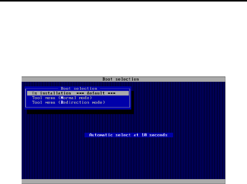
6-2 Installing and Using Utilities
NEC EXPRESSBUILDER
The NEC EXPRESSBUILDER helps you install the Operating system/the Management software or
use the maintenance utilities.
When you insert the NEC EXPRESSBUILDER DVD into the optical disk drive and reboot the
system, the following menu appears.
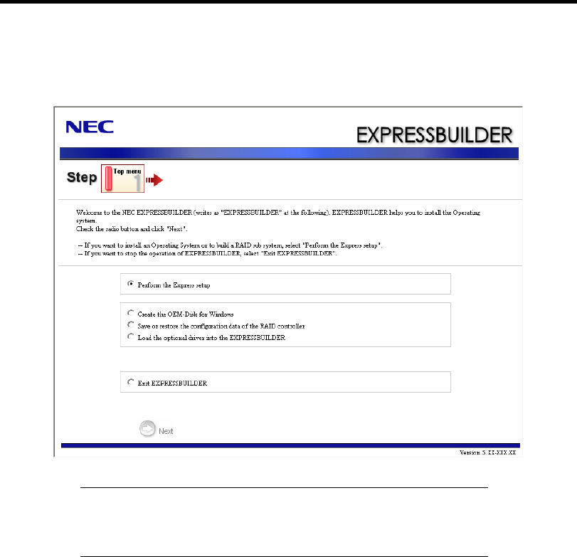
Installing and Using Utilities 6-3
OS installation
If you select this item, the Top menu appears.
IMPORTANT: This tool is Configuration Tool that built on Windows
PE 3.0 technology.
Pay attention to the automatic reboot that occurs after 72 hours from
start.
You can use the Express Setup (see Chapter 5) or the following functions from this menu.
– Create the OEM-Disk
You can create the Windows OEM-Disk to use at the Windows manual setup.
– Load the driver
This function is not usually used. If you add the new device to the server, this function
may use. (See Chapter 5.)
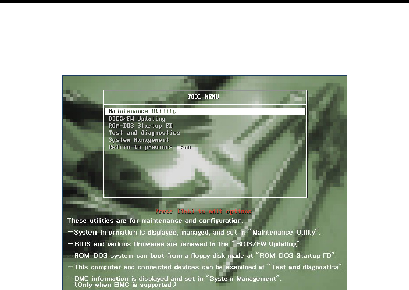
6-4 Installing and Using Utilities
Tool menu (Normal mode)
If you select this item, the Tool menu appears.
You can use the below functions for maintenance.
– Maintenance Utility
The Maintenance Utility is usually used by the service representative. (See Chapter 8.)
– BIOS/FW Updating
You can update the system BIOS by using the floppy disk (prepare a 3.5-inch floppy
disk).
– ROM-DOS Startup FD
The ROM-DOS Startup FD is used for starting the ROM-DOS system.
– Test and diagnostics
This function allows you to diagnose this computer. (See Chapter 7.)
– System Management
You can configure the parameters of BMC (Baseboard Management Controller).
This function is not supported in this server.
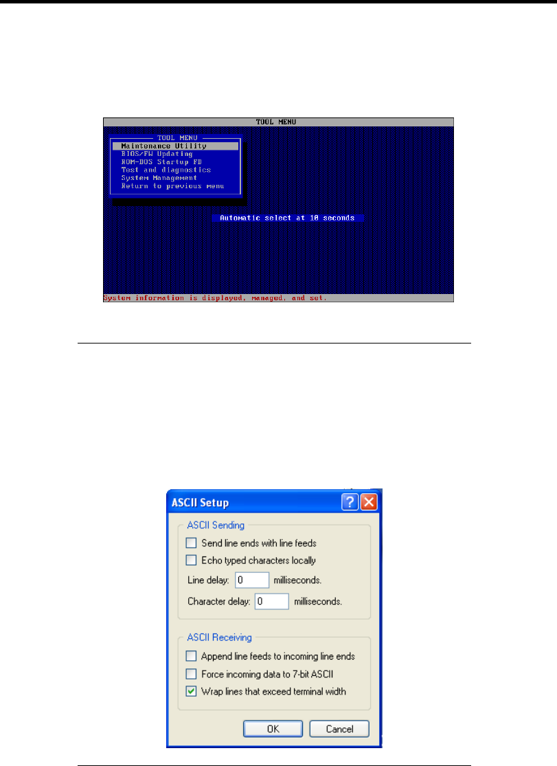
Installing and Using Utilities 6-5
Tool menu (Redirection mode)
If you want to operate this computer via the BIOS redirection (the console-less function),
select this item.
The menu's functions are the same as the "Tool menu (Normal mode)".
IMPORTANT: To use the Windows HyperTerminal Emulation
program on serial console, setup as shown below is required.
<Example: On Windows XP>
1. From the menu bar of HyperTerminal, select [File] - [Properties].
2. In the [Properties] dialog box, select [Settings] - [ASCII Setup].
Remove a checkmark from "Wrap lines that exceed terminal
width" checkbox.
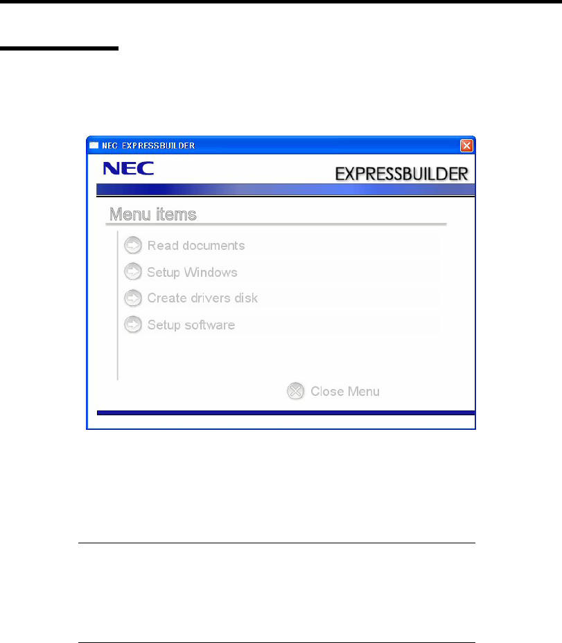
6-6 Installing and Using Utilities
Autorun Menu
When the NEC EXPRESSBUILDER DVD is inserted into the optical disk drive, Windows
automatically launches the menu as shown below.
This menu is used to,
Read the User's Guide or the other documents,
Update the server system (Windows drivers), and
Install the management software.
NOTES:
This menu requires Microsoft Windows XP, Vista or Windows
Server 2003 (or later).
Some documents are provided in PDF format. Use the Adobe
Reader to view or print these documents.
If the menu does not appear, select "My computer" by using the Explorer, and double-click the icon
of the optical disk drive that contains the NEC EXPRESSBUILDER DVD.
Some menu items are grayed-out when the logon user does not have the authority of the
administrator or the menu item is not available for your system.
To use the menu,
Click on the menu items, or
Click the right mouse button on the menu window.

Installing and Using Utilities 6-7
PARAMETER FILE CREATOR
"Parameter File Creator" is a tool to create [Parameter file] that is used for configuring the server
with the Express Setup (see Chapter 5 for details).
If you use the Parameter file created by the Express Setup and Parameter File Creator to operate the
setup, you can setup from the installation of OS to several utilities automatically except for a few
key input to confirm the specification. Also, you can install the system with the same specification
as before when re-installing the system. We recommend you to create [Parameter file] to setup the
servers from NEC EXPRESSBUILDER.
When using a floppy disk, a Flash FDD or USB FDD is required.
IMPORTANT:
You cannot create [Parameter file] for Windows Server 2003 x64
Editions.
The setup using a parameter file saved in the Flash FDD is not
supported.
NOTE: You can install Windows Server 2008 R2/Windows Server
2008/Windows Server 2003 without [Parameter file].
Also, you can modify/newly create [Parameter file] during the setup
with NEC EXPRESSBUILDER.
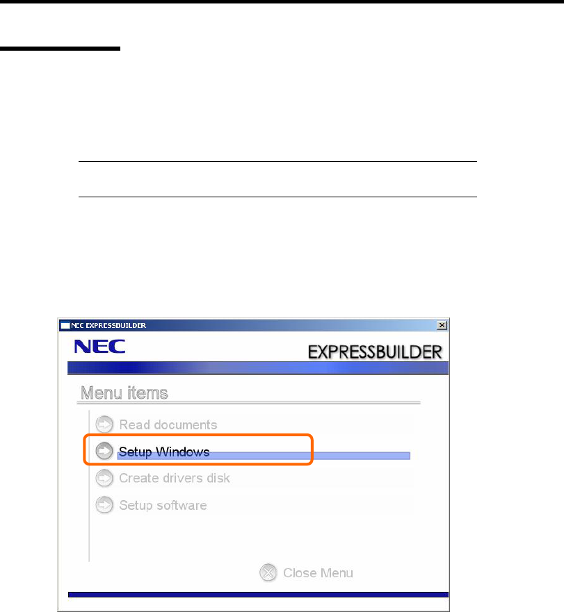
6-8 Installing and Using Utilities
Parameter File
This section describes about specifying setup information that is necessary for OS installation and
creating [Parameter file].
Follow the procedure below.
IMPORTANT: Do not remove NEC EXPRESSBUILDER DVD from
drive during a parameter file creation.
1. Start the OS.
2. Insert the NEC EXPRESSBUILDER DVD into the optical disk drive.
The menu will appear.
3. Right-click on the screen or left-click [Setup Windows]. The menu will appear.
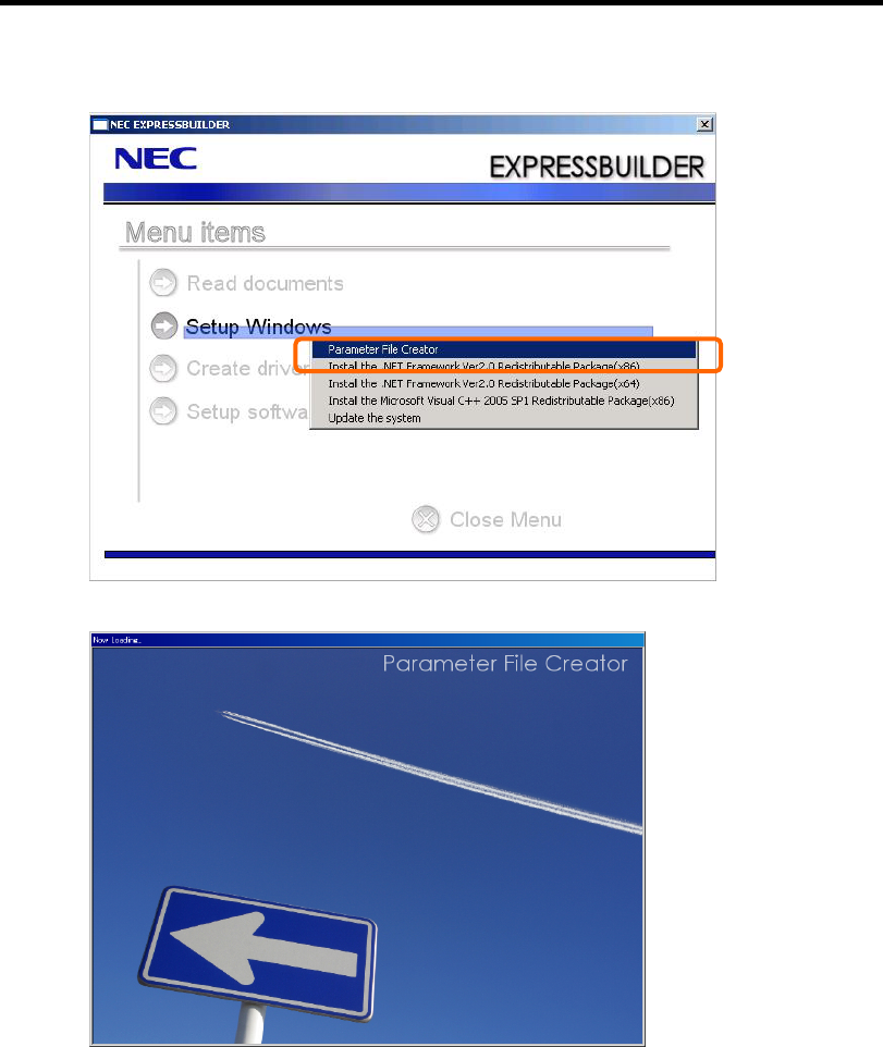
Installing and Using Utilities 6-9
4. Click [Parameter File Creator].
Parameter File Creator will appear.
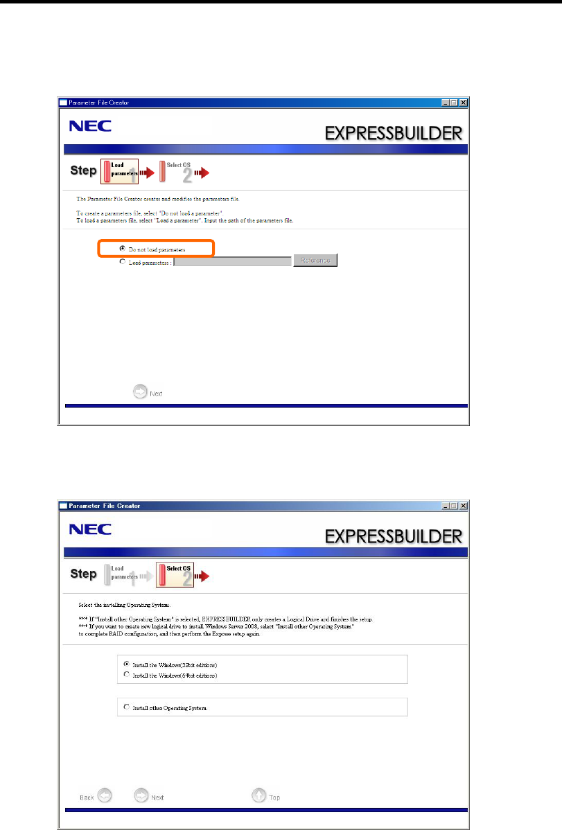
6-10 Installing and Using Utilities
5. [Load Parameters] step is displayed.
Select [Do not load parameters] from the menu, click [Next].
6. Select the installing Operating System.
Select [Install the Windows (32bit editions)] or [Install the Windows (64bit editions)]
from the menu, click [Next].
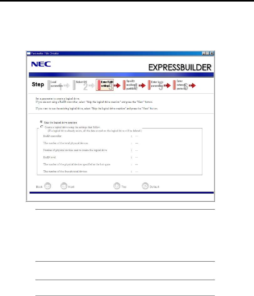
Installing and Using Utilities 6-11
7. Enter the setting of a logical drive.
[Enter RAID setting] steps are displayed. Confirm the parameters, modify if necessary,
and then click [Next].
IMPORTANT: At "The number of the total physical devices",
Parameter File Creator displays upper limit that the RAID Controller
can support.
The total of "The number of physical devices used to create the logical
drive" and "The number of the physical devices specified as the hot
spare" must not exceed "The number of the total physical devices"
which connected to the target system.
NOTE: You can use only the physical devices that have same model
number to configure logical drive.
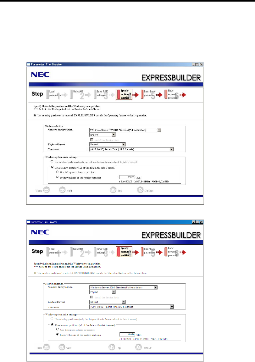
6-12 Installing and Using Utilities
8. Specify the installing medium and the Windows system partition.
[Specify medium / Partition] steps are displayed. Confirm the parameters, modify if
necessary, and then click [Next].
[Windows Server 2008 R2]
[Windows Server 2008]
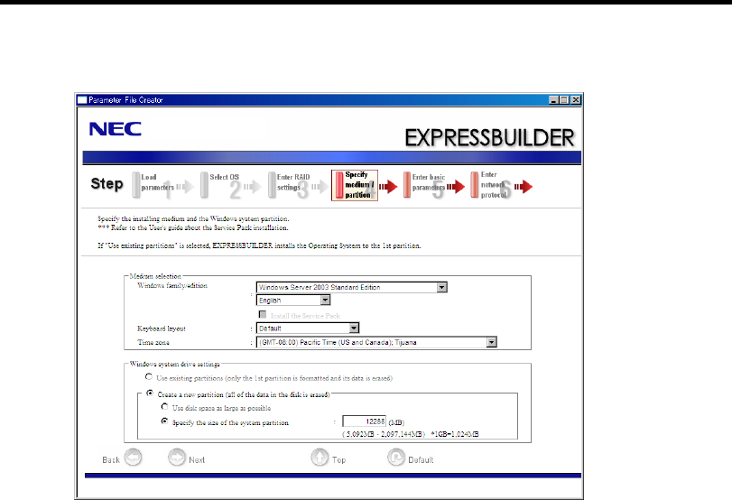
Installing and Using Utilities 6-13
[Windows Server 2003]

6-14 Installing and Using Utilities
IMPORTANT:
If you install Windows Server 2003 R2 and Service Pack, apply
Windows Server 2003 R2 DISC 2 after Express Setup completion,
and then install Service Pack by "Updating the system".
About partition size
– Specify the partition size larger than required minimum size for
OS installation.
– Do not specify larger partition size than the capacity of
connected hard disk drive.
– You can not specify a logical drive larger than 2,097,144MB at
RAID system.
If you select "Create a new partition" at "Windows system drive
settings", the contents of the hard disk will be all deleted.
If "Use existing partitions" is selected when you operate Windows
Server 2008 R2, NEC EXPRESSBUILDER installs the Operating
System to the Windows partition (The Boot partition (if it exists)
and the Windows partition are deleted).
The data in the other partition is kept if the system has two or more
partitions. (See the figure below.)
Boot
Partition
Deleted
Windows
Partition
Deleted
User Data
Partition
Retained
If "Use existing partitions" is selected when you operate Windows
Server 2008 or Windows Server 2003, NEC EXPRESSBUILDER
installs the Operating System to the 1st partition (1st partition is
deleted). The data in the other partition is kept if the system has
two or more partitions. (See the figure below.)
First
Partition
Deleted
Second
Partition
Retained
Third
Partition
Retained
You can not re-install the system with the existing partition that is
upgraded to Dynamic Disk remained. Do not select "Use existing
partitions" at "Windows system drive settings".
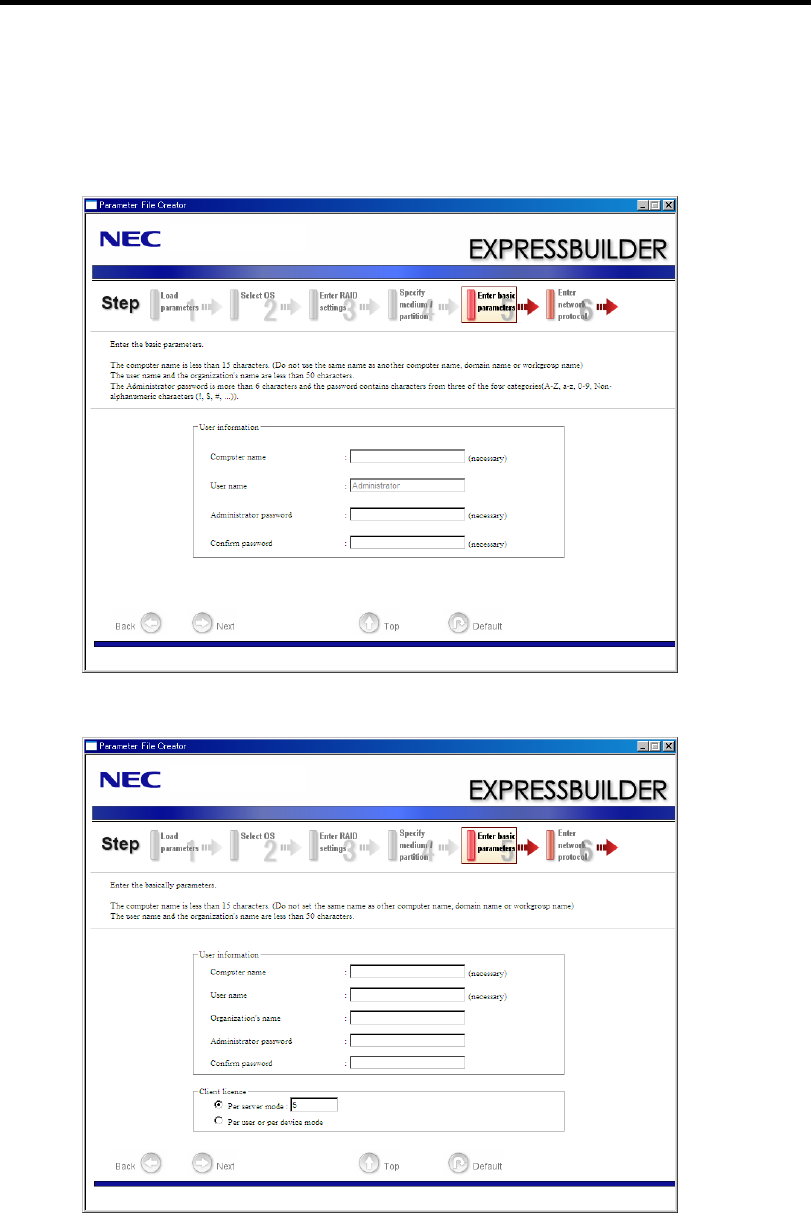
Installing and Using Utilities 6-15
9. Enter the user information and client license mode.
[Enter basic parameters] steps are displayed.
Confirm the parameters, modify if necessary, and then click [Next].
[Windows Server 2008 R2/Windows Server 2008]
[Windows Server 2003]
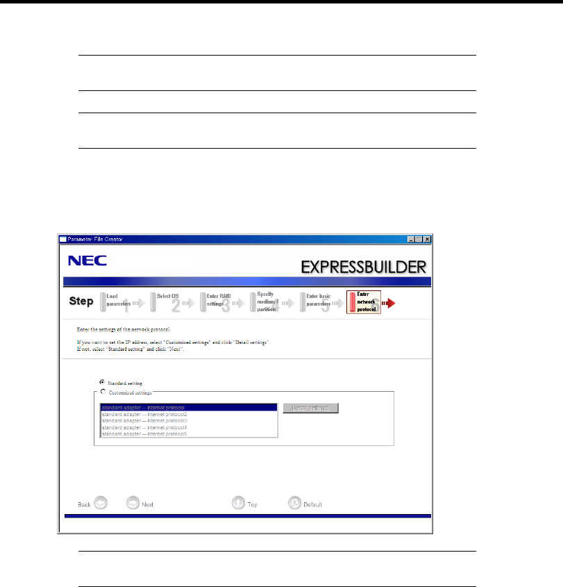
6-16 Installing and Using Utilities
IMPORTANT: Computer name and User name are required
parameters.
NOTE: Even if you do not input value into "Administrator password",
"Confirm password", "zzzzz" is displayed.
10. Enter the setting of the network protocol.
[Enter network protocol] steps are displayed. Confirm the parameters, modify if necessary,
and then click [Next].
NOTE: The order of entry in custom setting may differ from the
numbering of LAN port.
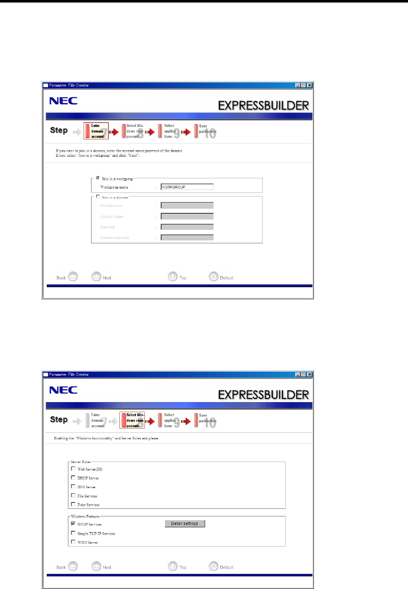
Installing and Using Utilities 6-17
11. Enter the domain or workgroup name to be used.
[Enter domain account] steps are displayed. Confirm the parameters, modify if necessary,
and then click [Next].
12. Select the installing components.
[Select Windows components] steps are displayed. Confirm the parameters, modify if
necessary, and then click [Next]
[Windows Server 2008 R2/Windows Server 2008]
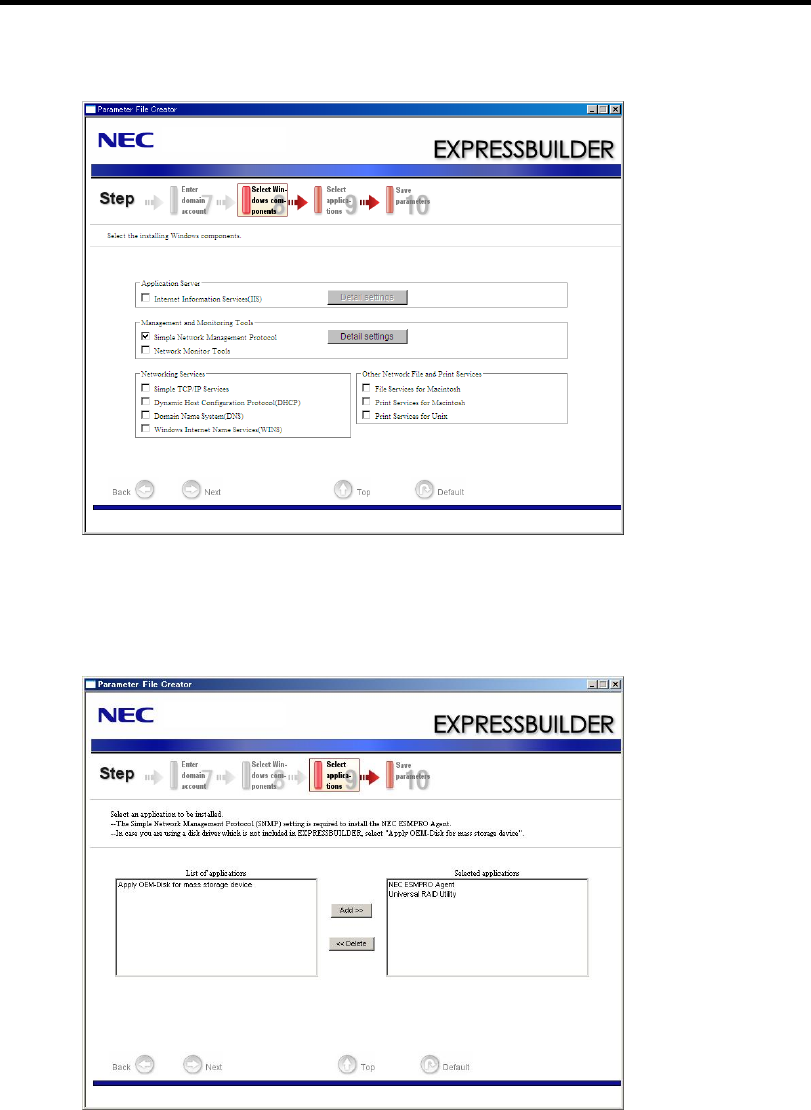
6-18 Installing and Using Utilities
[Windows Server 2003]
13. Select the installing applications.
[Select applications] steps are displayed. Confirm the parameters, modify if necessary, and
then click [Next].
[Windows Server 2008 R2/Windows Server 2008]
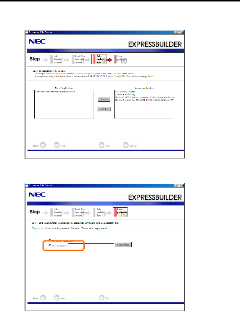
Installing and Using Utilities 6-19
[Windows Server 2003]
14. Save the parameters.
[Save parameters] steps are displayed.
If you want to save the parameters, set the free formatted floppy disk.
Select [Save parameters], enter the file path of the parameters files into the text box and
click [Next].
If not, select [Do not save parameters].
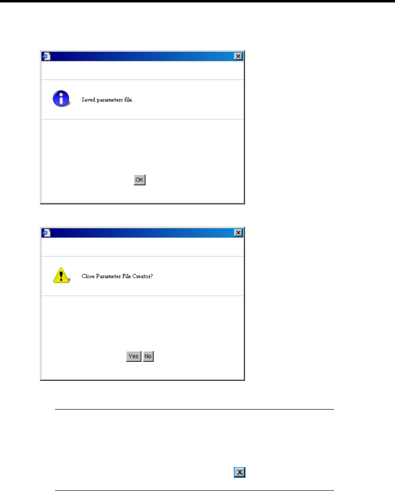
6-20 Installing and Using Utilities
15. Saved to a floppy disk.
Now [the floppy disk containing the parameters file] has been created.
Click [Yes] to exit Parameter File Creator.
NOTES:
If you modify existing information file (parameter file), click
"Load Parameters" at [Load Parameters] screen. Refer to help to
modify information file.
If you cancel operation on the way, click at the upper-right
corner of the screen.

Installing and Using Utilities 6-21
NEC ESMPRO
The NEC ESMPRO lets a system administrator manage remote servers across a network. NEC
ESMPRO monitors server hardware and software configurations, failures, and performance. With
log data collected by NEC ESMPRO, a system administrator can track long-term and short-term
performance, monitor server usage, and check server failure rates. The administrator can use the
information collected to create more efficient data routing procedures and optimize server usage.
Functions and Features
The NEC ESMPRO offers many functions and features for managing remote servers across a
network. These features help the system administrator perform daily system operation, system
extension, and transfer tasks. Some features of NEC ESMPRO Manager include:
Hardware and software server configuration
– Hardware resources mounted in servers, such as the CPU, memory, disks, RAID
System, and LAN boards.
– Software resources, such as operating system information and drivers running on each
server.
Server failures
– On-screen real-time displays provide the system administrator with the failure type,
location, cause, and suggested corrective action.
– Failure data includes hardware failure information such as system board temperature,
memory failure, crashes, and software failure information.
Performance
– NEC ESMPRO monitors server performance and displays server usage on the screen
and displays information, such as the rate of CPU load, memory usage, disk usage, and
LAN traffic. Usage threshold values can help the system administrator monitor and
prevent server overloads.
For installation procedure and detailed explanations on NEC ESMPRO, refer to the online
document in the NEC EXPRESSBUILDER DVD.

6-22 Installing and Using Utilities
NEC ExpressUpdate Agent
The NEC ExpressUpdate Agent enables you to control the version of the firmware and software that
is installed on the server. Using the NEC ESMPRO Manager, you can download update packages
automatically and install them simply without terminating the system. Refer to "Installation
Manual" in the NEC EXPRESSBUILDER for more information about an installation and functions
of the NEC ExpressUpdate Agent.
IMPORTANT: To get the information of the update package which
does not support NEC ExpressUpdate, refer to the web site below.
http://www.nec.com/global/prod/express/index.html

Installing and Using Utilities 6-23
Universal RAID Utility
Universal RAID Utility is an application to manage or monitor the following RAID Controllers.
LSI Embedded MegaRAID™
N8103-109 RAID Controller (128 MB, RAID0/1/5/6)
N8103-116A RAID Controller (128 MB, RAID0/1)
N8103-117A RAID Controller (128 MB, RAID0/1/5/6)
Before attempting to operate Universal RAID Utility, read the "Universal RAID Utility Ver2.1
User's Guide" contained in NEC EXPRESSBUILDER DVD. The manual explains the installation
procedure and notes on operating Universal RAID Utility.
Setup with Express Setup
You can install Universal RAID Utility with Express Setup contained in NEC EXPRESSBUILDER
DVD. When you start the Express Setup, a dialog to specify an application appears. Select
[Universal RAID Utility] on the dialog.
Manual Setup
Windows
You can start the setup program of Universal RAID Utility from [Autorun Menu].
Click [Setup Software] → [Universal RAID Utility] in [Autorun Menu].
You need to install the following software.
Microsoft .NET Framework 2.0 or later
The Runtime component of the Microsoft Visual C++ 2005 SP1
You can install these software from [Autorun Menu] too.
Click [Setup Windows] → [Install the .NET Framework Ver 2.0 Redistributable Package (x86)] (If
CPU architecture is x64, [Install the .NET Framework Ver2.0 Redistributable Package (x64)]) in
[Autorun Menu] for the setup of Microsoft.NET Framework 2.0.
Click [Setup Windows] → [Install the Microsoft Visual C++ 2005 SP1 Redistributable
Package(x86)] (Use the x86 package whatever the CPU architecture may be.) for the setup of the
Runtime component of the Microsoft Visual C++ 2005 SP1.
Microsoft .NET Framework
To use the RAID Viewer and Log Viewer, Microsoft .NET Framework Version 2.0 or
higher is required.
Windows Server 2008 and Windows Server 2008 R2, Windows Vista, Windows 7
include .NET Framework Version 2.0 or higher. Therefore, you do not need to
install .NET Framework in case of using them.

6-24 Installing and Using Utilities
Runtime component of Microsoft Visual C++ 2005 SP1 library
To use the RAID Viewer, the runtime component of the Microsoft Visual C++ 2005 SP1
library is required.
Windows Server 2008 and Windows Server 2008 R2, Windows Vista SP1 or later,
Windows 7 include the runtime component of the Microsoft Visual C++ 2005 SP1 library.
Therefore, you do not need to install the runtime component of the Microsoft Visual C++
2005 SP1 library in case of using them as operating system.
Management of RAID System using NEC ESMPRO Manager
Using NEC ESMPRO Manager (Ver. 5.2 or later) allows you to view, monitor, and operate the
RAID System managed by the Universal RAID Utility. This feature is available on Windows system
only.
See the instruction of NEC ESMPRO Manager about system requirements and how to use.
Easy Configuration
You can not use the function of Easy Configuration to LSI Embedded MegaRAID™.
Creating Logical Drive of RAID 6
Use WebBIOS when you create the Logical Drive of RAID 6 by using three Physical Devices.
Universal RAID Utility cannot create the Logical Drive of RAID 6 by using three Physical Devices.
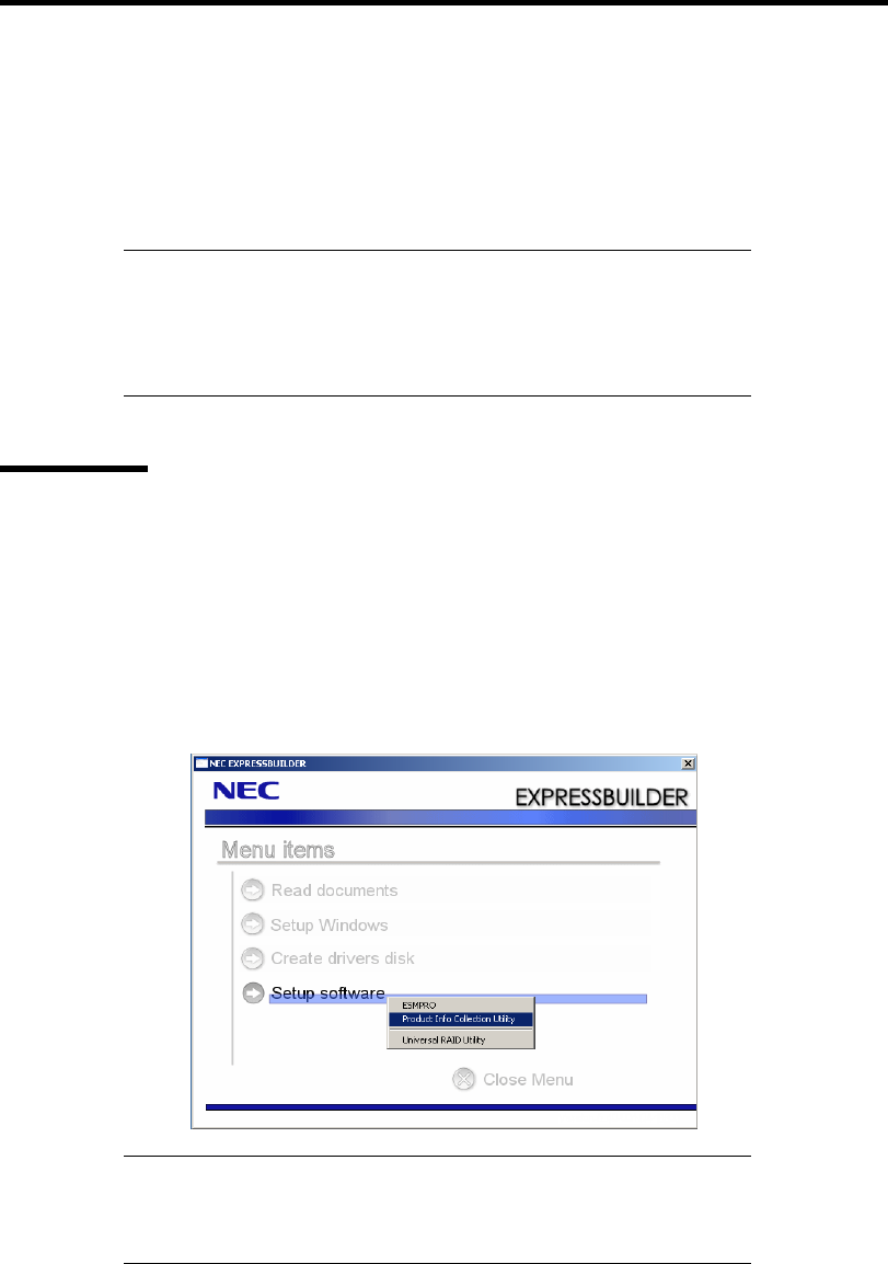
Installing and Using Utilities 6-25
NEC PRODUCT INFO COLLECTION UTILITY
The NEC Product Info Collection Utility is used to collect various system configuration and log
information for maintenance or troubleshooting purpose of the server.
This utility can be installed from NEC EXPRESSBUILDER DVD.
NOTE: Supported Operating Systems of this utility is as follows.
Windows Server 2003
Windows Server 2003 x64 Editions
Windows Server 2008
Installation
You can install this utility according to the following procedure.
1. Insert NEC EXPRESSBUILDER DVD in the optical disk drive after OS starts.
2. Click from the menu displayed with Auto-run in order of [Setup software] → [Product
Info Collection Utility].
3. The installation of this utility is started. Thereafter, install it according to the message in
the dialog box. (In default, it is installed in "System drive: \ezclct" folder.)
IMPORTANT:
Log in the system in account with the administrator authority.
2.5GB or more free space is required for the installation drive.

6-26 Installing and Using Utilities
Using Utility
Execute \stdclct\collect.exe in the installation folder of this utility.
The log folder is made in the above-mentioned folder, and various information on this device is
stored in the data compressed file (zip form).
Uninstallation
Except for Server Core
Choose [Add or Remove Programs] - [Product Info Collection Utility (Vx.x.x)] from the control
panel. Thereafter, uninstall it according to the message in the dialog box.
For Server Core
Enter the following command from the command prompt.
Wmic product where name="Product Info Collection Utility" call uninstall

Chapter 7
Maintenance
This chapter describes the daily maintenance of the server and precautions when relocating or
storing the server.
MAKING BACKUP COPIES
NEC recommends you make backup copies of your valuable data stored in hard disk drives of the
server on a regular basis. For backup storage devices suitable for the server and backup tools,
consult with your service representative.
When you have changed the hardware configuration or BIOS configuration, select "System
Information Management" and then "Save" of the Off-line Maintenance Utility to make a backup
copy of the system information.
Also make a backup copy of the RAID configuration data if your system is in the RAID
configuration. When your hard disk drives have been auto-rebuilt due to a failure, it is
recommended to make a backup copy of the configuration data. To make a backup copy of the
configuration data, use the configuration utility that is resident in the FLASH memory on the
optional RAID Controller board. Refer to the manual supplied with the board.
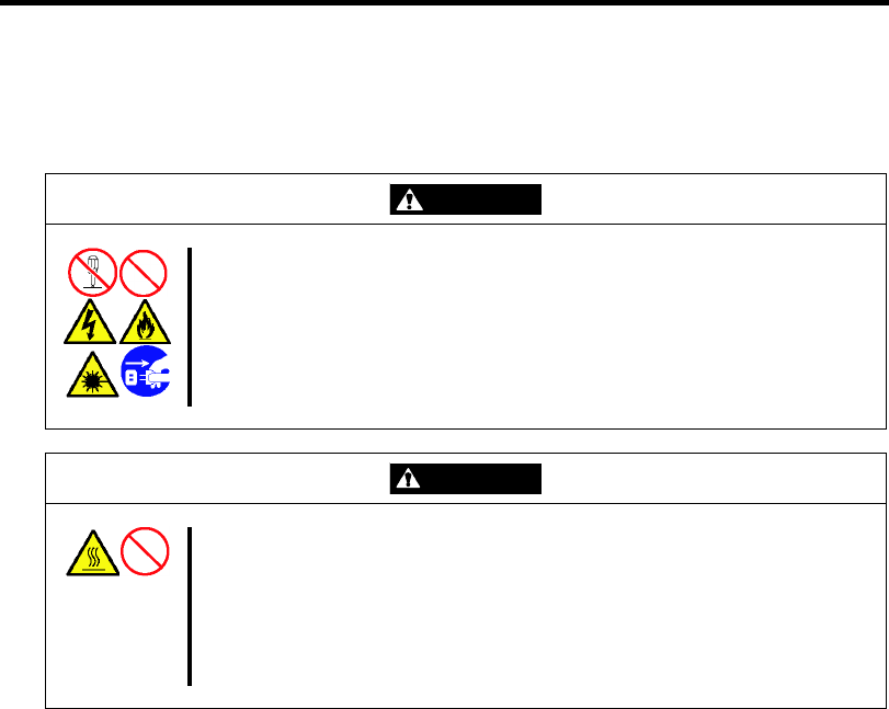
7-2 Maintenance
CLEANING
Clean the server on a regular basis to keep the server in a good shape.
WARNING
Observe the following instructions to use the server safely. Failure to follow
these instructions may result in death or serious personal injury. See pages
1-3 to 1-8 for details.
Do not disassemble, repair, or alter the server.
Do not remove the lithium battery.
Disconnect the power plug before working with the server.
CAUTION
Observe the following instructions to use the server safely. Failure to follow
these instructions may cause a fire, personal injury, or property damage. See
pages 1-3 to 1-8 for details.
Avoid installation in extreme temperature conditions.
Make sure to complete board installation.
Protect the unused connectors with the protective cap.

Maintenance 7-3
Cleaning the Server
For daily cleaning, wipe the external surfaces of the server with a dry soft cloth. Follow the
procedure below if stains remain on the surfaces:
IMPORTANT:
To avoid altering the material and color of the server, do not use
volatile solvents such as thinner and benzene to clean the server.
The power receptacle, the cables, the connectors on the rear panel of
server, and the inside of the server must be kept dry. Do not moisten
them with water.
1. Make sure that the server is off-powered (the POWER/SLEEP lamp goes off).
2. Unplug the power cord of the server from a power outlet.
3. Wipe off dust from the power cord plug with a dry cloth.
4. Soak a soft cloth in neutral detergent that is diluted with cold or lukewarm water, and
squeeze it firmly.
5. Rub off stains on the server with the cloth prepared in Step 4.
6. Soak a soft cloth in water, squeeze it firmly, wipe the server with it once again.
7. Wipe the server with a dry cloth.
8. Wipe off dust from the fan exhaust opening on the rear of the server with a dry cloth.
Cleaning the Keyboard/Mouse
Make sure that the server and peripheral devices are all off-powered (the POWER/SLEEP lamp
goes off), and then wipe the keyboard surface with a dry cloth.
The mouse does not work normally if its optical sensor is stained. Wipe the optical sensor with a dry
cloth.
Optical sensor

7-4 Maintenance
Cleaning Disc
A dusty disc or dust-accumulated tray causes the device to fail to read data correctly.
Follow the procedure below to clean the tray and disc regularly:
1. Make sure that the server is powered (the POWER/SLEEP LED is lit).
2. Press the CD tray Open/Close button on the front of the optical disk drive.
The tray opens.
3. Hold the disc lightly and take it out from the tray.
NOTE: Do not touch the signal side of the disc with your hand.
4. Wipe the tray with a dry soft cloth.
IMPORTANT: Do not wipe the lens of the optical disk drive. Doing
so may damage the lens and may cause a malfunction of the drive.
5. Push on the tray front to close the tray.
6. Wipe the signal side of the disc with a dry soft cloth.
IMPORTANT: Wipe disc from the center to the outside. Use only disc
cleaner if necessary. Cleaning a disc with record spray/cleaner, benzene,
or thinner causes damage to the disc contents. At worst, inserting the
disc into the server may cause failure.

Maintenance 7-5
SYSTEM DIAGNOSTICS
The System Diagnostics runs several tests on the server.
Select [Tool menu] - [Test and diagnostics] in the NEC EXPRESSBUILDER to diagnose the
system.
Test Items
The following items are tested in system diagnostics.
Memory
CPU cache memory
Hard disk drive used as a system
IMPORTANT: When executing the system diagnostics, make sure to
disconnect the LAN cable. Executing the system diagnostics with the
LAN cable connected, the network may be influenced.
NOTE: On checking the hard disk drive, no data is written into the
disk.
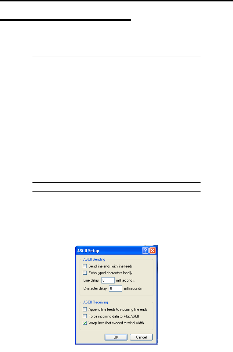
7-6 Maintenance
Startup and Exit of System Diagnostics
There are two ways to diagnose the server: to use the local console (keyboard) of the server itself,
and to use the management PC via serial port (remote console).
IMPORTANT: If you run the system diagnostics from the remote
console, set the baud rate for both BIOS and terminal software to 19200
bps.
Procedures to start the diagnostics program are as follows:
1. Shutdown the OS, and power off the server. Then, unplug the power cord.
2. Disconnect all the LAN cables from the server.
3. Plug the power cord and power on the server.
4. Use the NEC EXPRESSBUILDER DVD to start the system.
5. Select [Tool menu (Normal mode)] when local console of the server is used for, or select
[Tool menu (Redirection mode)] when remote console is used for.
NOTES:
If the system displays the [Language selection] menu, select
[English].
If the system displays "Hit any key.", please hit any key.
IMPORTANT: To use the Windows HyperTerminal Emulation program
on serial console, setup as shown below is required.
<Example: On Windows XP>
1. From the menu bar of HyperTerminal, select [File] - [Properties].
2. In the [Properties] dialog box, select [Settings] - [ASCII Setup].
Remove a checkmark from "Wrap lines that exceed terminal width"
checkbox.
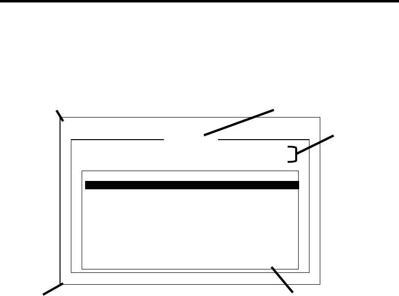
Maintenance 7-7
6. Select [Test and diagnostics].
Select [End-User Mode] and the system diagnostics starts. The diagnostics will be
completed in approximately three minutes. When the diagnostics is completed, the screen
of the display changes as shown below:
Diagnostics tool title
[Enter] Detail Information [ESC] Return to Enduser Menu
Test End
T
eDoLi (TEst & Diagnosis On Linux) Ver001.00 (Build020901.1.1m)
<System>
MEM Memory 16 count NormalEnd
CACHE Cache 49 count NormalEnd
<SCSI>
HDD_02:000 DK32DJ-36W 89 count NormalEnd
Start 10:06:58 End 10:09:58 Pass 000:03:00 TestTime 000:03:00
T
est End : NormalEnd 03 AbnormalEnd 00 ForceEnd 00
Guide line Tes t s umm ar y wi nd ow
Tes t res ult
Test window title
– Diagnostics tool title
Shows the name and version of the diagnostic tool.
– Test window title
Shows the progress of the diagnostics. "Test End" is displayed when the diagnostics
completes.
– Test result
Shows the start, end, and elapsed time and completion status of the diagnostics.
– Guide line
Shows the details of the keys to operate window.
– Test summary window
Shows the results of each test that executed the diagnostics. Move the cursor and
press the Enter key on the cursor line to display the details of the test.
When an error is detected by the system diagnostics, the relevant test result in the Test
summary window is highlighted in red, and "Abnormal End" is displayed in the result on
the right side.
Move the cursor to the test that detected the error, and press the Enter key. Record the
error message that has been output to the Detail Information screen and contact your
service representative.

7-8 Maintenance
7. Follow the guide line shown at the bottom of the screen, and press the Esc key.
The [Enduser Menu] below is displayed.
Enduser Menu
Please choose a function by the arrow key and push Enter key.
<Test Result>
<Device List>
<Log Info>
<Option>
<Reboot>
TeDoLi (TEst & Diagnosis On Linux) Ver001.00 (Build020901.1.1m)
Enduser Menu
<Test Result> Shows the diagnostics completion screen of the above diagnostics.
<Device List> Shows a list of connected devices.
<Log Info> Shows the log information of the diagnostics. Log information can be
saved.
To save it, connect a FAT formatted removable media, and select
<Save(F)>.
<Option> Optional features can be used from this menu.
<Reboot> Reboots the system.
8. Select <Reboot> in the [Enduser Menu] above.
The server restarts and the system is started from the NEC EXPRESSBUILDER.
9. Exit the NEC EXPRESSBUILDER, and remove the DVD from the optical disk drive.
10. Power off the server and unplug the power cord from the receptacle.
11. Reconnect all the LAN cables that have been disconnected in Step 2 to the server.
12. Plug in the power cord.
This completes the system diagnostics.
Maintenance 7-9
RELOCATING/STORING THE SERVER
Follow the procedure below to relocate or store the server:
CAUTION
Observe the following instructions to use the server safely. Failure to follow
these instructions may cause a fire, personal injury, or property damage. See
pages 1-3 to 1-8 for details.
Never attempt to lift the server only by yourself.
Do not install the server in any place other than specified.
Do not connect/disconnect any interface cable with the power cord of the
server plugged to a power source.
IMPORTANT:
If the server needs to be relocated/stored due to a change in the floor
layout to a great extent, contact the service representative.
Make sure to make a backup copy of your valuable data in the hard
disk drive, if any.
Make sure not to apply a shock to hard disk drives to relocated the
server if the contains any.
1. Take a media out of the server, if any.
2. Power off the server (the POWER/SLEEP lamp goes off).
3. Unplug the power cord of the server from a power outlet.
4. Remove all the cables from the server.
5. Hold the server by its bottom to carry the server.
IMPORTANT: Do not hold the front bezel to lift the server. The front
bezel may be disengaged from the server, causing personal injury.
6. Protect the server with the shock-absorbing materials, and pack it securely.

7-10 Maintenance
(This page is intentionally left blank.)

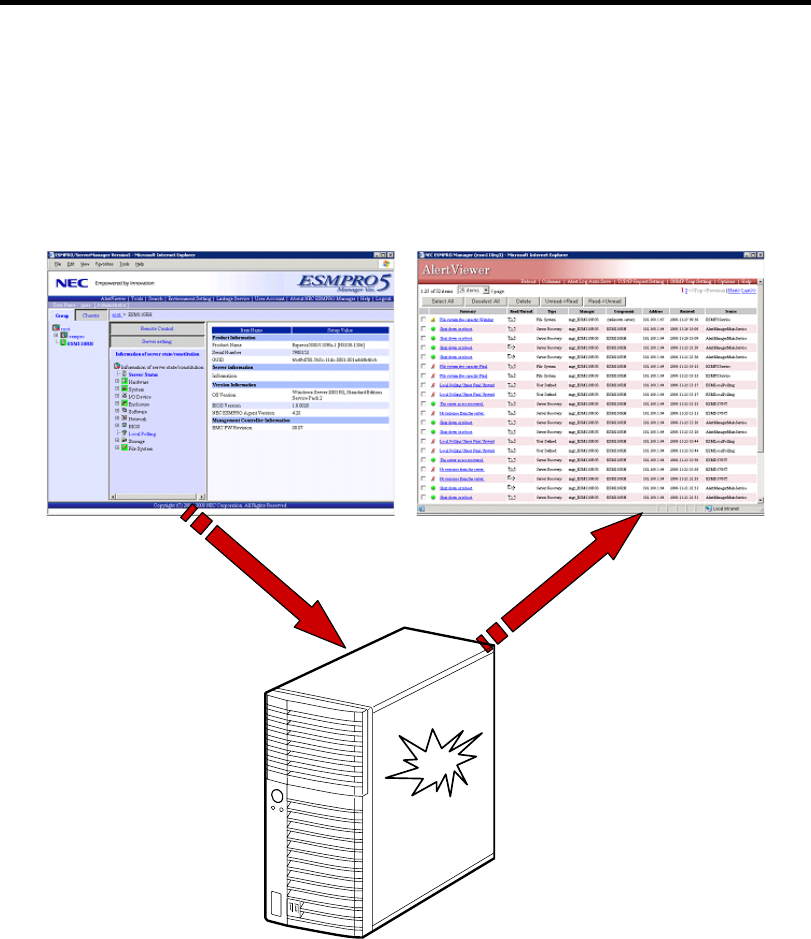
8-2 Troubleshooting
SYSTEM VIEWERS
Monitor the occurrence of fault by NEC ESMPRO during the system operation.
Especially take note on whether any alert is reported to NEC ESMPRO Manager on the language
PC. Check whether any alert is reported on NEC ESMPRO Manager.
[Example]
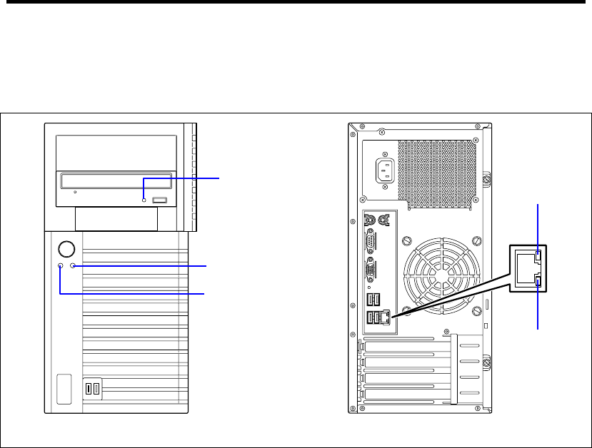
Troubleshooting 8-3
LAMPS
The following describes lamps on the server and their indications. See Chapter 2 for each location.
A
ccess lamp
POWER/SLEEP lamp
Disk access lamp
LINK/ACT
lamp
1000/100/10
lamp
FRONT REAR

8-4 Troubleshooting
POWER/SLEEP Lamp
The green POWER/SLEEP lamp lights to indicate normal operation while the server is powered.
When the server is off-powered, the POWER/SLEEP lamp stays unlit.
The POWER/SLEEP lamp indicates that the server is running in the power-saving mode (sleep
mode). If the OS supports the power-saving mode such as Windows, pressing the POWER/SLEEP
switch blinks the POWER/SLEEP lamp in green and places the server in the power-saving mode.
Press the POWER/SLEEP switch to turn out the POWER/SLEEP lamp and place the server back in
the normal mode.
The power-saving mode is only available when the OS supports the power-saving feature. Some
OS's allow you to set the server to automatically turn in the power-saving mode when no access is
made to the server for a certain period of time or to select the power-saving mode with a command.
DISK ACCESS Lamp
The DISK access lamp lights in green every time any of internal hard disk drive or optical disk
drive is accessed.
Access Lamp
The Access lamp for the optical disk drive lights when access is made to a media in the drive.
LINK/ACT Lamp
The link/ACT lamp indicates the state of each network port normally equipped with the server. If
the power is supplied to the server and the hub and they are correctly connected with each other, the
lamp is lit green (LINK state). If information is transmitted through a network port, the lamp blinks
green (ACT state).
If the lamp is not lit in the LINK state, check the network cable and the cable connection. If the
lamp is not lit still after the checking, the network (LAN) controller may be defected. Contact your
service representative.
1000/100/10 Lamp
The 1000/100/10 lamp indicates whether each of the network ports normally equipped with the
server is operated through the 1000BASE-T, 100BASE-TX or 10BASE-T network interface. If the
lamp is lit orange, the network port is operated through 1000BASE-T. If the lamp is lit green, the
network port is operated through 100BASE-TX. If the lamp is off, the network port is operated
through 10BASE-T.

Troubleshooting 8-5
ERROR MESSAGES
If an error occurs in the server, an error message appears on the display unit connected to the server.
Error Messages after Power-on
Powering on the server automatically starts the self-diagnostic program, POST (Power On
Self-Test). When the POST detects any error, it displays an error message and its measure on the
display unit.
Follow the table below to troubleshoot such errors. However, even when there is no hardware
failure, use of the keyboard or mouse at the following timing causes the POST to assume a
keyboard controller error and stop processing.
Immediately after the server is powered
Immediately after the system is rebooted in response to a keyboard instruction
(simultaneous key entry of Ctrl + Alt + Delete)
Immediately after the system is rebooted in response to an OS instruction
During hardware initialization following restart of the POST
When the POST detects a hardware failure due to the above reason, restart the server once again. If
the same error message reappears, you may assume there is no hardware error. To ensure normal
operation of the server, however, make sure to follow the following restrictions.
Do not make any keyboard entry or use the mouse before the memory count appears on
the screen following the server power-on.
Do not make any keyboard entry or use the mouse before the start-up message of the
Configuration Utility appears on the screen following the server reboot.
IMPORTANT: Take a note on the on-screen message before
contacting your service representative. The alarm indication would be a
great help for maintenance.

8-6 Troubleshooting
POST Error Messages
When POST detects an error, it displays an error message on the display unit screen. The following
table lists error codes, error messages, and actions to take.
IMPORTANT: Take a note on the messages displayed before
consulting with your service representative. Alarm messages are useful
information for maintenance.
NOTE: For the BIOS error messages related to the optional RAID
Controller or SCSI controller connected with the mother board, refer to
the relevant document provided with the optional controller.
Error
code Error message Recommended Action
0200 Failure Fixed Disk Contact your service representative.
0210 Stuck Key Disconnect the keyboard and connect it again.
0213 Keyboard locked - Unlock key
switch
Release the lock of the key switch. If the error cannot
be corrected in spite of the release of the lock,
contact your service representative.
0220 Monitor type does not match CMOS
- Run SETUP
Run BIOS SETUP and provide the setting again. If
the same error persists, contact your service
representative.
0230 System RAM Failed at offset:
0231 Shadow RAM Failed at offset:
0232 Extended RAM Failed at offset:
Contact your service representative.
0250 System battery is dead - Replace
and run SETUP
Contact your service representative to replace the
lithium battery. (After restarting the computer, run
BIOS SETUP to provide the setting again.)
0251 System CMOS checksum bad -
Default configuration used
The default values have been set. Run BIOS SETUP
to provide the setting again. If the same error
persists, contact your service representative.
0252 Password checksum bad -
Passwords cleared
The password has been cleared. Run BIOS SETUP
to set the password again.
0260 System timer error
0270 Real time clock error
0271 Check date and time settings
Run BIOS SETUP to set date and time again. If the
same error persists, contact your service
representative.
02D0 System cache error - Cache
disabled
Contact your service representative.
02D1 System Memory exceeds the
CPU's caching limit.
02F4 EISA CMOS not writable
02F5 DMA Test Failed
02F6 Software NMI Failed
02F7 Fail-safe Timer NMI Failed
Contact your service representative.
0613 Com A configuration changed
0614 Com A config. error - device
disabled
Check if COM A is properly configured.

Troubleshooting 8-7
Error
code Error message Recommended Action
0615 Com B configuration changed
0616 Com B config. error - device
disabled
Check if COM B is properly configured.
0B00 WDT timeout occurred at previous
boot in POST.
0B01 WDT timeout occurred at previous
boot in OS boot.
0B02 WDT timeout occurred at previous
boot in OS running.
Reboot (reset) the server. If the server starts
normally, confirm the DMI log.
0B28 Unsupported CPU detect on CPU
Slot
Contact your service representative.
0B60 DIMM group #1 has been disabled
0B61 DIMM group #2 has been disabled
0B62 DIMM group #3 has been disabled
0B63 DIMM group #4 has been disabled
0B6F DIMM group with error is enabled
Contact your service representative.
0B7E Mismatched FAN control Mode
setting. Please set the FAN control
mode on BIOS SETUP.
Run BIOS SETUP and provide setting again.
0BB0 SMBIOS - SROM data read error.
0BB1 SMBIOS - data checksum bad.
Contact your service representative.
8151 Password Cleared By Jumper Power off the server, then change the password clear
jumper switch to its original position.
8800 PECI - Communication Error Contact your service representative.
9000 PCI Slot#1 PCIE Link Training
Error.
9001 PCI Slot#2 PCIE Link Training
Error.
9002 PCI Slot#3 PCIE Link Training
Error.
Remove the PCI card from the slot that shows an
error, then install the PCI card again. If the same
error persists, contact your service representative.
- Expansion ROM not initialized - PCI
Mass Storage Controller in slot xx
If the hard disk drive connected to RAID Controller or
LAN board (for network boot) does not contain any
OS, disable Option ROM Scan for that PCI slot.

8-8 Troubleshooting
Beep Codes
If an error occurs during the POST, the server beeps, indicating the type of error.
Each number indicates the number of short beeps, and a hyphen indicates a pause. For example, the
beep interval 1-3-1-1 indicates 1 beep, pause, 3 beeps, pause, 1 beep, pause, and 1 beep notifying
that the DRAM refresh test error occurred.
Beep code Description Recommended action
3-3
(repetitive)
1-2-2-3
ROM checksum error Contact your service representative to replace
the mother board.
1-3-1-1 DRAM refresh test error Check if the DIMMs are properly connected. If
the error persists, contact your service
representative to replace DIMM or mother
board.
1-3-1-3 Keyboard controller error Disconnect the keyboard and connect it again.
If the error persists, contact your service
representative to replace the mother board.
1-3-3-1 No memory or capacity check
error
1-1-1-1 DRAM address error
1-3-4-3 DRAM test Low Byte error
1-4-1-1 DRAM test High Byte error
Check if the DIMMs are properly installed. If
the error persists, contact your service
representative to replace DIMM or mother
board.
2-1-2-1 BIOS ROM copyright test error
2-2-3-1 Unexpected interrupt test error
Contact your service representative to replace
the mother board.
1-2 Option ROM initialization error Check if BIOS SETUP is correctly configured.
If an expansion of Option ROM for additionally
installed PCI board is not displayed, check if
the PCI board is properly installed. If the error
persists, contact your service representative to
replace the mother board or PCI board.
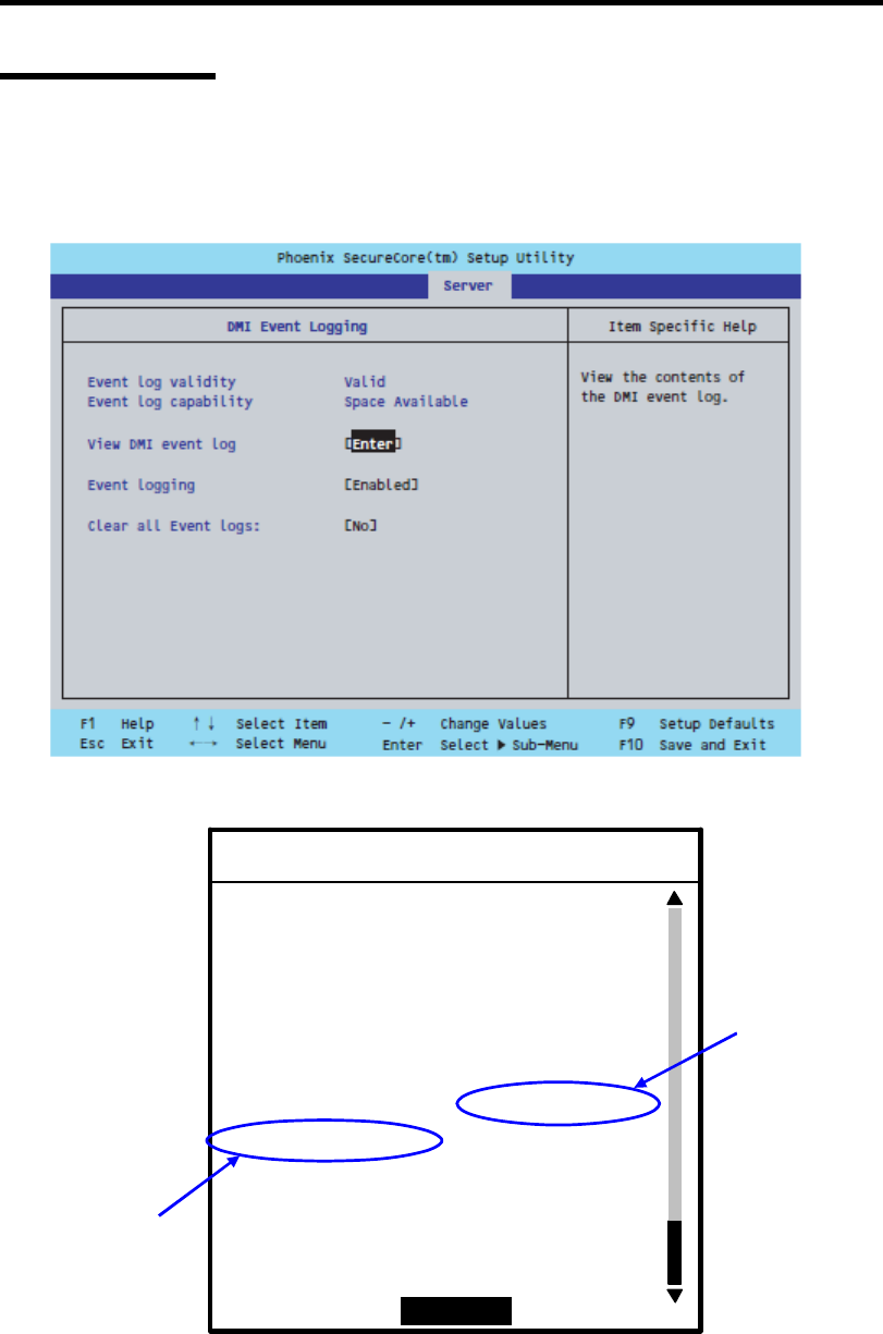
Troubleshooting 8-9
DMI Event Log
In the BIOS setup Server menu, select "DMI Event Logging”, select [Enter], which is next to View
DMI event log, and then press Enter.
The DMI event log saved in the system can be displayed.
02/14/2010 09:13:24 System Boot :
02/14/2010 10:08:52 System Boot :
02/14/2010 16:48:24 System Boot :
02/14/2010 16:58:41 WDT timeout :
WDT Info :0095
02/14/2010 16:58:42 POST Error :
POST Error Code :0B00
[]
DMI Event Log
Continue
Log Info
Log Info2

8-10 Troubleshooting
DMI Event Log Messages
Log info Log info2 Description Recommended action
Error Info:
0100
A correctable error
occurred for DIMM #1.
Error Info:
0200
A correctable error
occurred for DIMM #2.
Error Info:
0300
A correctable error
occurred for DIMM #3.
Memory
Correctable
Error Info:
0400
A correctable error
occurred for DIMM #4.
Restart the equipment, and then run the
BIOS SETUP utility. Check the DIMM status
(DIMM Group #1 to #4 Status) displayed in
“Memory Configuration”, which is on the
Advanced menu.
Check whether the DIMM for which the error
occurred is inserted correctly, and then
restart the equipment. If this does not
resolve the problem, contact your service
representative.
Error Info:
0100
An uncorrectable error
occurred for DIMM #1.
Error Info:
0200
An uncorrectable error
occurred for DIMM #2.
Error Info:
0300
An uncorrectable error
occurred for DIMM #3.
Memory
Uncorrecta
ble
Error Info:
0400
An uncorrectable error
occurred for DIMM #4.
Restart the equipment, and then run the
BIOS SETUP utility. Check the DIMM status
(DIMM Group #1 to #4 Status) displayed in
“Memory Configuration”, which is on the
Advanced menu.
Check whether the DIMM for which the error
occurred is inserted correctly, and then
restart the equipment. If this does not
resolve the problem, contact your service
representative.
PCI PERR Error Info:
XXXX
A parity error occurred
for PCI #4.
PCI SERR Error Info:
XXXX
A system error
occurred for PCI #4.
Check whether the optional card in PCI slot
#4 is inserted correctly, and then restart the
equipment. If this does not resolve the
problem, contact your service
representative.
Error Info:
80XX
An uncorrectable error
occurred for the
on-board LAN.
Restart the equipment. If this does not
resolve the problem, contact your service
representative.
Error Info:
90XX
An uncorrectable error
occurred for PCI #1.
Error Info:
A0XX
An uncorrectable error
occurred for PCI #2.
PCIe
UncErr
Error Info:
B0XX
An uncorrectable error
occurred for PCI #3.
Check whether the optional card in the PCI
slot for which the error occurred is inserted
correctly, and then restart the equipment. If
this does not resolve the problem, contact
your service representative.
POST
Error
POST Error
Code:
XXXX
A POST error
occurred.
For the recommended action, see "POST
Error Messages".
WDT Info:
00XX
The watchdog timer
timed out last time the
POST was started.
Restart the equipment. If this does not
resolve the problem, contact your service
representative.
WDT Info:
00C0
The watchdog timer
timed out last time the
OS was started.
Restart the equipment. If this does not
resolve the problem, contact your service
representative.
WDT
timeout
WDT Info:
01C0
The watchdog timer
timed out last time the
OS was running.
Restart the equipment. If this does not
resolve the problem, contact your service
representative.
Log Area
Cleared
(None) The DMI log area was
initialized and the log
was deleted.
This is not an error.
System
Boot
(None) The POST finished. This is not an error.

Troubleshooting 8-11
SOLVING PROBLEMS
When the server fails to operate as expected, see the following to find out your problem and follow
the instruction given before asking for repair.
If the server still fails to operate successfully after solving your problem, take a note on the
on-screen message and contact your service representative.
Problems with NEC Express Server
No screen display appears and beep occurs.
Is the DIMM board installed securely?
→ Check whether the DIMM board is inserted into the mating connector securely.
→ Make sure the jumper switches have been returned to their original positions after
CMOS clearing. See "Configuring Mother Board Jumpers" in Chapter 4 for the
positions of the jumper switches.
Fail to power on the server:
Is the server is properly supplied with power?
→ Check if the power cord is connected to a power outlet (or UPS) that meets the
power specifications for the server.
→ Check the power cord for broken shield or bent plugs.
→ Make sure the power breaker for the connected power outlet is on.
→ If the power cord is plugged to a UPS, make sure the UPS is powered and it
outputs power. See the manual that comes with the UPS for details.
Power supply to the server may be linked with the connected UPS using the BIOS
Setup utility of the server.
<Menu to check: [Advanced] - [AC-LINK]>
Did you press the POWER/SLEEP switch?
→ Press the POWER/SLEEP switch on the front of the server to turn on the power
(the POWER/SLEEP lamp lights).

8-12 Troubleshooting
POST fails to complete:
Is the DIMM board installed?
→ Check the installation location of DIMMs (see Chapter 9).
Is the memory size large?
→ The memory check may take a few seconds if the memory size is large. Wait for a
while.
Did you perform any keyboard or mouse operation immediately after you started the
server?
→ If you perform any keyboard or mouse operation immediately after start-up, POST
may accidentally detect a keyboard controller error and stops proceeding. In such
a case, restart the server once again. Do not perform any keyboard or mouse
operation until the BIOS start-up message appears when you restart the server.
Does the server have contains appropriate memory boards or PCI devices?
→ Operation of the server with unauthorized devices is not guaranteed.
Fail to access to internal or external devices (or such devices fail to operate):
Are cables properly connected?
→ Make sure that the interface cables and power cord are properly connected. Also
make sure that the cables are connected in the correct order.
Is the power-on order correct?
→ When the server has any external devices connected, power on the external
devices first, then the server.
Did you install drivers for connected optional devices?
→ Some optional devices require specific device drivers. Refer to the manual that
comes with the device to install its driver.
Is BIOS configuration correct?
→ Some devices connected to the serial or parallel port may require I/O port address
or operation mode settings. Refer to the manual that comes with the board for
details to make correct settings.

Troubleshooting 8-13
The keyboard or mouse fails to operate:
Is the cable properly connected?
→ Make sure that the cable is connected to the correct connector on the rear of the
server.
→ The keyboard or mouse does not operate if it is connected when the server is
powered (not applicable to USB devices). Power of the server first and connect it
properly.
Are the server drivers installed?
→ Refer to the manual that comes with your OS to check that the keyboard and
mouse drivers are installed. (These drivers are installed along with the OS.) Some
OS's allow you to change the keyboard and mouse settings. Refer to manual that
comes with your OS to check that the keyboard and mouse settings are correct.
Fail to access (read or write) to the floppy disk:
Does the floppy disk drive contain a floppy disk?
→ Insert a floppy disk into the floppy disk drive until it clicks.
Is the floppy disk write-protected?
→ Place the write-protect switch on the floppy disk to the "Write-enabled" position.
Is the floppy disk formatted?
→ Use a formatted floppy disk or format the floppy disk in the floppy disk drive.
Refer to the manual that comes with the OS for formatting a floppy disk.
Are the cables properly connected?
→ Make sure that the interface cable and the power cable (or cord) are connected to
the correct connector of the server. Also make sure the connection order is correct.
Is BIOS configuration correct?
→ You must change the BIOS configuration as follows to use the internal floppy disk
drive.
<Menus to check: [Main] - [Legacy Diskette A:] - [1.44/1.25MB 3 2/1"]>
Save the setting and restart the server. Run BIOS SETUP again, and select [Boot]
- [Excluded from boot order] and press x on [Legacy Floppy Drives] to move it to
[Boot priority order]. Then, press + to move it to desired priority order.
* The position next to "CD-ROM" is recommendable.

8-14 Troubleshooting
Fail to access to the DVD/CD-ROM:
Is the DVD/CD-ROM properly set in the optical disk drive tray?
→ The tray is provided with a holder to secure the DVD/CD-ROM. Make sure that
the DVD/CD-ROM is placed properly in the holder.
Is the DVD/CD-ROM applicable to the server?
→ The DVD/CD-ROM for Macintosh is not available for use.
→ For the disk which does not conform to the CD standard, the playback of such a
disk with the optical disk drive is not guaranteed.
The POWER/SLEEP lamp goes on when the power cord is connected:
→ When the server receives an AC power after the power cord is connected, the
POWER/SLEEP lamp goes on. This is a normal operation of the server, not a fault.
The lamp will go off when DC power is turned on, and then off.
Inserted the correct DVD/CD-ROM but the message like the following is displayed:
The DVD/CD-ROM is not inserted or the wrong DVD/CD-ROM is inserted.
Please insert the correct DVD/CD-ROM.
OK
Is the data side of the DVD/CD-ROM dirty or injured?
→ Take the DVD/CD-ROM out of the optical disk drive, confirm that it is not dirty
or injured, reset and click [OK].
Fail to access the hard disk drive:
(Refer to the documentation supplied with the RAID Controller.)
Is the hard disk drive applicable to the server?
→ Operation of any device that is not authorized by NEC is not guaranteed.
Is the hard disk drive properly installed?
→ See Chapter 9.

Troubleshooting 8-15
Fail to access the (internal or external) SCSI devices:
Is the SCSI device applicable to the server?
→ Operation of any SCSI device that is not authorized by NEC is not guaranteed.
Is the cable connection changed?
→ See Chapter 10 for cable connection.
Are SCSI devices properly configured?
→ When the server has external SCSI devices connected, hard disk drive settings,
including SCSI ID and terminator, are required. Refer to the manual that comes
with the SCSI device for details.
Is cable length exceeded?
→ Refer to the manual that comes with the SCSI device for details.
Are the optional SCSI controllers properly configured?
→ Use the BIOS Setup utility for proper configuration of SCSI devices connected to
the SCSI connector on the mother board. When the server has an optional SCSI
controller installed and SCSI devices connected to it, use the BIOS Setup utility
that comes with the optional SCSI controller for proper configuration. See the
manual that comes with the optional SCSI controller for details.

8-16 Troubleshooting
Event logs in using Intel Network adapter teaming
Event Type: Warning
Event Source: iANSMiniport
Event Category: None
Event ID: 11
Description: Adapter link down:Intel(R) ----
Event Type: Warning
Event Source: iANSMiniport
Event Category: None
Event ID: 13
Description: Intel(R) ---- has been deactivated from the team.
Event Type: Warning
Event Source: iANSMiniport
Event Category: None
Event ID: 16
Description: [Team Name]: The last adapter has lost link.
Team network connection has been lost.
Event Type: Warning
Event Source: iANSMiniport
Event Category: None
Event ID: 22
Description: Primary Adapter does not sense any Probes:
Intel(R) ---- Possible reason: partitioned Team.
→ Above-mentioned event log will appear when the system starts.
There is no problem in LAN driver operation.

Troubleshooting 8-17
Problems with Windows
The following warnings are logged when you start Windows Server 2008 R2/Windows Server
2008:
Event ID: 27
Source: e1qexpress
Level: Warning
Description: Intel(R) 82574L Gigabit Dual Port Server Network ...
Network link has been disconnected.
→ If the above event is logged when you start the system, this event does not affect
system operation. Ignore this message.
Event ID: 63
Source: Microsoft-Windows-WMI
Level: Warning
Description: A provider, Ncs2, has been registered in the Windows Management
Instrumentation namespace Root\IntelNCS2 to use the LocalSystem
account.
This account is privileged and the provider may cause a security violation
if it does not correctly impersonate user requests.
→ This event does not affect system operation. Ignore this message.
The following system event is logged when Windows Server 2008 R2 is installed:
Event ID: 134
Source: Microsoft-Windows-Time-Service
Level: Warning
Description: NtpClient was unable to set a manual peer to use as a time source because
of DNS resolution error on ''.
NtpClient will try again in 3473457 minutes and double the reattempt
interval thereafter.
The error was: No such host is known. (0x80072AF9)
→ This event does not affect system operation. Ignore this message.

8-18 Troubleshooting
The following application event is logged when Windows Server 2008 R2 is installed:
Event ID: 1534
Source: Microsoft-Windows-User Profiles Service
Level: Warning
Description: Profile notification of event Create for component
{56EA1054-1959-467f-BE3B-A2A787C4B6EA} failed, error code is The
revision level is unknown.
→ This event does not affect system operation. Ignore this message.
The following system event is logged when I use the system recognizing iSCSI:
Event ID: 1
Source: iScsiPrt
Level: Error
Description: Initiator failed to connect to the target. Target IP address and TCP Port
number are given in dump data.
→ Go to the Microsoft website:
http://support.microsoft.com/default.aspx/kb/976072/en-us
The following warnings are logged to application event log when you import a transportable
shadow-copy to another server that has a read-only volume while operating Windows Server
2008 R2:
Event ID: 8193
Source: VSS
Level: Error
Description: Volume Shadow Copy Service error: Unexpected error calling routine
IOCTL_DISK_GET_DRIVE_LAYOUT_EX(\\?\mpio#disk&ven_nec&pro
d_istorage_2000&rev_2800#1&7f6ac24&0&303030303030303933313030
303735373030323934#{ GUID }) - BuildLunInfoForDrive.
hr = 0x80070013, This media is write-protected.
Event ID: 12289
Source: VSS
Level: Error
Description: Volume Shadow Copy Service error: Unexpected error
DeviceIoControl(\\?\storage#volume#{ GUID }#0000000000010000#
{ GUID } - 00000000000002B8,0x00560000,0000000000000000,0,
00000000002BE0C0,4096,[0]).
hr = 0x80070013, This media is write-protected.
→ Go to the Microsoft website:
http://support.microsoft.com/kb/2003016/en-us

Troubleshooting 8-19
The following warnings are logged to application event log when I import a transportable
shadow-copy to another server that has a floppy disk drive while operating Windows Server
2008 R2:
Event ID: 12289
Source: VSS
Level: Error
Description: Volume shadow copy service error: unexpected error
DeviceIoControl (\\? # 6 \usbstor#sfloppy &ven_teac&prod_fd-05pub
&rev_3000 & 158e20d0 & 0 # { GUID }-00000000000002B8,
0x00560000, 0000000000000000, 0, 0000000000327C70,4096, [0]).
HR = 0x80070032, this request is not supported.
→ Go to the Microsoft website:
http://support.microsoft.com/kb/2003968/en-us
There is the case that the following message is displayed at the time of shutdown when you
executes “Updating the system” in Windows Server 2008 R2:
1 program still needs to close: (Waiting for) Task Host Window
→ This event does not affect system operation.
Ignore this message. For more details, see
http://support.microsoft.com/kb/975777/en-us
The following system events are logged when Windows Server 2008 is installed:
Event ID: 134
Source: Microsoft-Windows-Time-Service
Level: Warning
Description: NtpClient was unable to set a manual peer to use as a time source because
of DNS resolution error on 'time.windows.com,0x9'. NtpClient will try
again in 15 minutes and double the reattempt interval thereafter.
The error was: No such host is known. (0x80072AF9)
Event ID: 263
Source: PlugPlayManager
Level: Warning
Description: The service 'ShellHWDetection' may not have unregistered for device
event notifications before it was stopped.
Event ID: 7000
Source: Service Control Manager
Level: Error
Description: The Parallel port driver service failed to start due to the following error:
The service cannot be started, either because it is disabled or because it has
no enabled devices associated with it.

8-20 Troubleshooting
Event ID: 15016
Source: Microsoft-Windows-Http
Level: Error
Description: Unable to initialize the security package Kerberos for server side
authentication. The data field contains the error number.
→ These events do not affect system operation. Ignore these messages.
The following application events are logged when Windows Server 2008 is installed.
Event ID: 63
Source: Microsoft-Windows-WMI
Level: Warning
Description: A provider, Ncs2, has been registered in the Windows Management
Instrumentation namespace Root\cimv2 to use the LocalSystem account.
This account is privileged and the provider may cause a security violation
if it does not correctly impersonate user requests.
A provider, IntelEthernetDiag, has been registered in the Windows
Management Instrumentation namespace Root\CIMv2 to use the
LocalSystem account. This account is privileged and the provider may
cause a security violation if it does not correctly impersonate user requests.
A provider, WmiPerfClass, has been registered in the Windows
Management Instrumentation namespace root\cimv2 to use the
LocalSystem account. This account is privileged and the provider may
cause a security violation if it does not correctly impersonate user requests.
Event ID: 6000
Source: Microsoft-Windows-Winlogon
Level: Warning
Description: The winlogon notification subscriber <GPClient> was unavailable to
handle a notification event.
Event ID: 6001
Source: Microsoft-Windows-Winlogon
Level: Warning
Description: The winlogon notification subscriber <GPClient> failed a notification
event.
→ These events do not affect system operation. Ignore these messages.

Troubleshooting 8-21
The following system event is logged when Windows Server 2008 is installed.
Event ID: 10
Source: VDS Dynamic Provider
Description: The provider failed while storing notifications from the driver.
The Virtual Disk Service should be restarted. hr=80042505
→ Go to the Microsoft website:
http://support.microsoft.com/kb/948275/en-us/
The following application events are logged when Windows Server 2008 is installed.
Event ID: 1021
Source: Microsoft-Windows-Security-Licensing-SLC
Level: Warning
Description: SLUINotify service has failed to start. hr=0x80070424
Event ID: 1534
Source: Microsoft-Windows-User Profiles Service
Level: Warning
Description: Profile notification of event Create for component
{56EA1054-1959-467f-BE3B-A2A787C4B6EA} failed, error code is
-2147023591.
→ These events do not affect system operation. Ignore these messages.
There are some cases that an event log is registered as follows when you install Windows
Server 2003 x64 Editions.
Source: DCOM
Category: Error
Event ID: 10016
Description: The application-specific permission settings do not grant Local Activation
permission for the COM server application with CLSID
{555F3418-D99E-4E51-800A-6E89CFD8B1D7} to the user {NT
AUTHORITY\LOCAL SERVICE} SID {S-1-5-19}.
This security permission can be modified using the component Services
administrative tool.
→ It is not a problem in operating the system.

8-22 Troubleshooting
There are some cases that an event log is registered as follows when you install Windows
Server 2003 x64 Editions.
Event Source: Service Control Manager
Event Type: Error
Event ID: 7011
Description: Timeout (30000 milliseconds) waiting for a transaction response from the
IMAP4Svc service.
→ When this event is not registered by rebooting the system, it is not a problem in
operating the system.
Installed Service Pack before application of Windows Server 2003 R2 DISC 2 during Windows
Server 2003 R2 installation.
→ Apply Windows Server 2003 R2 DISC 2, and then install Service Pack again by
"Updating the System".
There are some cases that an event log is registered as follows when you operate Windows
Server 2003 R2.
Source: IPMIDRV
Type: Error
Event ID: 1001
Description: The IPMI device driver attempted to determine if the system supported an IPMI BMC
device. The driver attempted to detect the presence of the IPMI BMC by searching the
SMBIOS for Type 38 record. But either no record was found or the record was not
compatible with the version of the device driver.
If a SMBIOS Type 38 record was detected, the Dump Data field of the event contains
a binary representation of the record.
→ If you use "Hardware Management" which is provided by Windows Server 2003
R2, above-shown event log will be registered.
For more details, refer to "Enabling Microsoft Windows Server 2003 R2
Hardware Management" on the following site.
[NEC Express5800 Web Site]
http://www.nec.com/global/prod/express/download/W2K3_R2/index.html
Troubleshooting 8-23
The system displays the message below and fails to log on.
Windows Product Activation
This copy of Windows must be activated with Microsoft before you can
continue. You cannot log on until you activate Windows.
To shut down the computer, click Cancel.
YES NO Cancel
→ In Windows Server 2003, the above message will be displayed if you use the
operating system without executing the license authentication. Select "Yes", and
execute the procedure for license authentication.
Cannot install the operating system correctly.
Did you confirm the notes on installing the operating system?
→ See Chapter 6.
Fail to start the OS with the /3GB switch
→ System often fails to start the OS with the /3GB switch.
In this case, adjust the capacity of the user mode area using the /userva switch in
reference to the following URL.
http://support.microsoft.com/kb/316739/en
During installation, the following warning is registered in the System Log of the Event Viewer:
Error detected on the device \Device\CdRom0
during the paging operation.
→ There is no problem on this issue.
Fail to start the OS:
Is a floppy disk in the floppy disk drive?
→ Take out the floppy disk and restart the server.
Is the NEC EXPRESSBUILDER DVD in the optical disk drive?
→ Take out the NEC EXPRESSBUILDER DVD and restart the server.
Is the OS broken?
→ Use recovery process to recover the system.

8-24 Troubleshooting
The OS presents unstable operation:
Did you update the system?
→ Installing a network drive after installation of the OS may cause unstable
operation. Use the NEC EXPRESSBUILDER DVD to update the system. (See
Chapter 6.)
The system does not restart automatically when a stop error occurs, though the system is
adjusted to automatically restarting:
→ When the system does not restart automatically, restart it manually.
The system restarts automatically when a stop error occurs, though the system is NOT
adjusted to automatically restarting:
→ There is no problem about this issue.
Check the System Event Log to confirm that STOP error occurred.
Cannot turn the power OFF at the blue screen:
→ If you want to turn off the power at the blue screen, execute forced shutdown
(forced shutdown: continue to press POWER/SLEEP switch for 4 seconds). The
power will not be turned off if you press the switch for less than 3 seconds.
The PXE boot (network boot) fails or the server is not found on the network:
Is the cable connected properly?
→ Connect the proper cable to the network port on the rear of the Express server. In
addition, make sure that the used cable conforms to the network interface standard.
Is BIOS configuration correct?
→ The internal LAN controller may be disabled with the BIOS SETUP utility of the
server. Check the setting with the BIOS setup utility.
Have the protocol and service already configured?
→ Install the distinctive network driver for the server. Make sure that the protocol,
such as TCP/IP, and services are properly specified.
Is the transfer speed correct?
→ Open the network property dialog box in control panel to specify the link speed
and duplex value the same as the value specified for HUB.

Troubleshooting 8-25
The Telnet Service is not installed.
→ Adjust the computer name to 14 characters or less, and then install the Telnet Service
according to <How to install the Telnet Service>.
<How to install the Telnet Service>
1. Click [Run] on Start menu.
2. Type "tlntsvr /service" in the [Open] box, and click [OK].
3. Click Start menu, point to [Control Panel] and click [Computer Management] and then
click the [Services] to specify whether the Telnet Service is registered.
* When the installation of Telnet Service is finished, there is no problem if the computer
name is set to 15 characters or more.
Power ON/OFF (Wake On LAN) feature does not work:
→ Immediately after the AC power is turned on, the Remote Power ON/OFF feature
(Wake ON LAN) is disabled. Start Windows 2003 once, provide settings as shown
below, then shutdown the system. After restart, the Remote Power On/Off feature is
available unless the AC power is turned off.
Select [Start] → [Administrative Tools] → [Computer Management].
Select Device Manager, double-click [Intel(R) PRO/1000EB Network Connection
with I/O Acceleration #n] under Network Adapter, and specify as follows in [Detail]
tab.
PME: [ON]
Wake On: [Magic Packet]
The system time lags:
→ If you do not use the server that adjusts time such as NTP (Network Time Protocol)
Server, the system time may differ from actual time.
In this case, use NTP server or disable "Windows Time Service".
Fail to access to USB devices on Windows Server 2003 x64 Edition or Windows Server 2003:
Did you apply [Hotfix for Windows x64 "KB921411"] or [Hotfix for Windows Server
2003 (KB921411)] prior to the "Updating the System" process?
Specify whether "!" is displayed or not on the USB root hub.
<verification process>
Click Start menu, right-click [My Computer], and click [Manage] to start Device
Manager.
And then, select [Device Manager] from the left side window.
→ If "!" is displayed on the USB root hub, apply the Hotfix according to the
"Recovery process".
For "Recovery process", see Appendix F or Appendix G for details.

8-26 Troubleshooting
Fail to restart the system with the message means "pci.sys missing or corrupt" after you
executed "Updating the System" process to Windows Server 2003 x64 Edition or Windows
Server 2003:
During the application of the ChipSet driver by "Updating the System" process, the
driver for the USB device may be deleted.
Follow the process detailed below.
(1) Start the Recovery console.
(2) Copy "<Systemdrive>\system32\dllcache\pci.sys" to under
"<Systemdrive>\system32\drivers".
(3) Exit the Recovery console, and restart the system.
(4) Refer to "Recovery process" and follow to the process detailed to apply [Hotfix
for Windows x64 "KB921411"] or [Hotfix for Windows Server 2003
(KB921411)] and "Updating the System".
For "Recovery process", see Appendix F or Appendix G for details.
During installation, the following message is registered in the DMI Event Log:
PCI Express Correctable.
→ This message might be registered in the log during installation, but there is no
problem on operation.

Troubleshooting 8-27
Problems with NEC EXPRESSBUILDER
When the server is not booted from the NEC EXPRESSBUILDER DVD, check the following:
Did you set the NEC EXPRESSBUILDER during POST and restart the server?
→ If you do not set the NEC EXPRESSBUILDER during POST and restart the
server, an error message will appear or the OS will boot.
Is BIOS configuration correct?
→ The boot device order may be specified with the BIOS SETUP utility of the server.
Use the BIOS Setup utility to change the boot device order to boot the system
from the optical disk drive first.
<Menu to check: [Boot]>
Did you connect an unformatted Flash FDD or insert an unformatted floppy disk?
→ Please connect a formatted Flash FDD or insert a formatted floppy disk.
If [Os installation ***default***] is selected at Boot selection screen, following
message is displayed.
After this message appears, check the error and take the appropriate corrective action
according to the message listed in the table below.
Message Cause
This EXPRESSBUILDER version was not
designed for this computer.
Insert the correct version and click [OK].
(When you click [OK], the computer reboots.)
This NEC EXPRESSBUILDER version is
not designed for this server.
Execute the NEC EXPRESSBUILDER on
the compliant server.
EXPRESSBUILDER could not get the
hardware parameters written in this
motherboard.
This version is not designed for this computer
or the motherboard may be broken. (When
you click [OK], the computer reboots.)
The hardware parameters written in this
motherboard are incorrect.
This version is not designed for this computer
or the motherboard may be broken.
This message is shown when NEC
EXPRESSBUILDER could not find
system-specific information because of
mother board exchange and so on.
If the creation of the OEM-Disk for Windows failed, the following message will be
displayed.
Confirm the message, and then try the solution described in the "Cause".
Error message Cause
The format went wrong. It is write-protected
or the floppy disk may be damaged. Please
check a floppy disk and perform creation of
OEM-Disk again.
Failed in the deletion of the file. Please
confirm whether the media is not
write-protected state or not.
The Flush FDD or the floppy disk is
write-protected.
Cancel write-protected state.
If you have already canceled
write-protected state, connect the USB
floppy disk drive again.

8-28 Troubleshooting
Problems with Express Setup
Specified to join the Domain, but the system is installed as Workgroup.
→ When the setup fails to join the Domain during the installation, it will install the
system as Workgroup. Open [System] in Control Panel to specify joining the Domain.
Unable to specify the details of Network adapter.
→ In Express Setup, you can not specify the details of Network adapter. Specify them
from Control Panel after starting Windows.
There is unused area on the lead of HDD.
Did you install Windows Server 2003?
→ If you had installed Windows Server 2003 by Express Setup, the head 8MB of
HDD may be unused area.
It is not a problem in operating the system.
Product key was not asked.
Case of Windows Server 2008
→ If you install using BackUp DVD-ROM, product key is not required.
If you install using the DVD-ROM other than BackUp DVD-ROM, product key
screen is displayed twice, at "during OS installation" and "before [MICROSOFT
SOFTWARE LICENSE TERMS] dialog, which displayed after OS installation".
Enter product key following the message.
Case of Windows Server 2003
→ If you install using BackUp CD-ROM, product key is not required.
If you install using the DVD-ROM other than BackUp DVD-ROM, product key
screen is displayed during OS installation.
Enter Product Key following the message.

Troubleshooting 8-29
When IIS is installed with Windows Server 2008 by Express Setup, following feature is
installed.
Windows Process Activation Service
– Process Model
– Configuration APIs
Remote Server Administration Tool
– Role Administration Tools
– Web Server (IIS) Tools
→ The feature listed above is activated because they are required for the installation
of IIS basic feature.
Problems with Parameter File Creator
Fail to start Parameter File Creator:
Parameter File Creator requires to run by "Microsoft® HTML Application host".
→ If Parameter File Creator does not start, associate the file type with "Microsoft®
HTML Application host" via following process.
1) Click [Run] on Start menu.
2) Type "%windir%\system32\mshta.exe /register" in the [Open] box, and click
[OK].

8-30 Troubleshooting
Problems with RAID System Configuration
Check the following if the server configuring a RAID System does not operate properly or a utility
does not operate correctly. If a relevant item is found, follow the processing method.
Fail to install the OS:
Is the RAID Controller configured?
→ Provide proper configuration for the RAID Controller by using the LSI Software
RAID Configuration Utility.
Fail to start the OS:
Is the BIOS of the RAID Controller changed?
→ Set the BIOS correctly by using the LSI Software RAID Configuration Utility.
Does POST recognize the RAID Controller?
→ After making sure that the RAID Controller is connected correctly, then power on
the server.
If the RAID Controller is not recognized correctly despite correct connection, the
RAID Controller may be failed. Contact your service representative.
Rebuild fails:
Is the capacity of the hard disk drive to be rebuilt sufficient?
→ The hard disk drive to be rebuilt should have the same capacity of the failed had
disk drive.
Is RAID0 configured?
→ RAID0 has no data redundancy, therefore, Rebuild is disabled in the RAID0
configuration. Replace the failed hard disk drive, create the configuration data
again and initialize the hard disk drives. Then recover the data by using backup
data.
Auto rebuild fails:
Was a sufficient time taken for hot swap of hard disk drives?
→ To allow the auto rebuild to operate correctly, it should take 90 seconds or longer
for the interval between the removal of the failed hard disk drive and the
installation of a new hard disk drive.
Is configuration correct?
→ Check the setting of auto rebuild by using the LSI Software RAID Configuration
Utility. <Menus to check: Top menu - [Objects] - [Adapter] - [Auto Rebuild]>

Troubleshooting 8-31
A hard disk drive fails:
→ Contact your service representative.
Physical device is not correctly displayed on Universal RAID Utility
→ If you use LSI Embedded MegaRAID™, a part of information on a physical device is
not correctly displayed on Universal RAID Utility.
It is no problem.

8-32 Troubleshooting
Problems with Windows Autorun Menu
Cannot read online document:
Do you have Adobe Reader installed correctly in your system?
→ Some online documents are supplied with PDF format. To read the document of
PDF format, Adobe Reader is required in your system.
Is the operating system Windows XP SP2?
→ With Windows XP SP2, the following information may appear in browser.
"To help protect your security, Internet Explorer has restricted this file from
showing active content that could access your computer. Click here for options..."
1. Click the Information Bar.
The shortcut menu appears.
2. Click [Allow blocked content].
The security alert dialog box appears.
3. Click [Yes] on dialog box.
The menu fails to appear:
Is your system Windows XP or later, or Windows 2003 or later?
→ The Windows Autorun menu is supported by Windows XP/Windows 2003 or later.
→ If your system runs on Windows Autorun Menu on Windows 2000 system, you
need to setup IE6.0 before using Windows Autorun Menu.
Is Shift pressed?
→ Setting the DVD/CD-ROM with Shift pressed down cancels the Autorun feature.
Is the system in the proper state?
→ The menu may not appear depending on the system registry setting or the timing
to set the DVD/CD-ROM. In such a case, start the Explorer and double-click the
icon of the optical disk drive.
Some menu items are grayed-out:
Is your system environment correct?
→ The menu items are grayed-out when the logon user does not have the authority of
the Administrator or the system does not meet the requirements to install the
application. Login with the user having the proper authority on the proper system,
and try again.
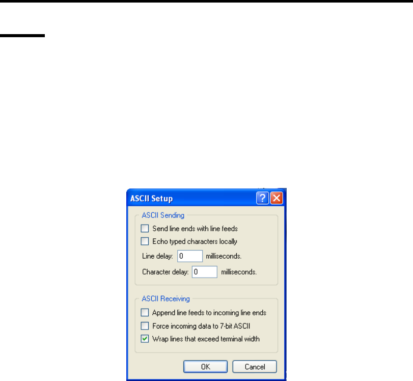
Troubleshooting 8-33
Others
The HyperTerminal screen on serial console scrolls automatically:
→ To use the Windows HyperTerminal Emulation program on serial console, setup
as shown below is required.
<Example: On Windows XP>
1. From the menu bar of HyperTerminal, select [File] - [Properties].
2. In the [Properties] dialog box, select [Settings] - [ASCII Setup].
Remove a checkmark from "Wrap lines that exceed terminal width" checkbox.

8-34 Troubleshooting
Collecting Event Log
This section describes on how to collect the log of various events that occurred on the server.
IMPORTANT: If STOP error, system error, or stall occurred, follow
the procedure below after restarting the system.
1. Click [Management Tool] → [Event Viewer] from the Control Panel.
2. Select the type of the log to collect.
On [Application Log], the events related to the running application is archived. On
[Security Log], the events related to the security is archived. On [System Log], the events
occurred at the item which configures Windows system is archived.
3. Click [Save as...] in the [Run] menu.
4. Input the file name of archived log in the [File Name] box.
5. Select the type of the log file you want to save in the [File Type] list box and click [OK].
For more information, refer to Windows Online Help.
Collect Configuration Information
This section describes on how to collect the information on hardware configuration and inside
specification.
In order to collect information, "Diagnostic Program" is used.
IMPORTANT: If STOP error, system error, or stall occurred, follow
the procedure below after restarting the system.
1. Point to [Settings] in Start menu, and click [Control Panel].
The [Control Panel] dialog box appears.
2. Double-click [Management Tool], and double-click [Computer Management].
The [Computer Management] dialog box appears.
3. Click [System Tool] → [System Information].
4. Click [Save as System Information File] in the [Operation] menu.
5. Input the file name to save in the [File Name] box.
6. Click [Save].

Troubleshooting 8-35
Collecting Dr. Watson Diagnostic Information
Dr. Watson collects diagnostic information related to application errors. The location to save the
information can be specified as you like. For more information, see Chapter 5.
Memory Dump
If an error occurs, the dump file should be saved to acquire necessary information.
If you saved the dump to DAT, write down that it is saved as "NTBackup" or "ARCServe" on the
label. You can specify the location to save the diagnostic information as you like. For more
information, see "Specifying Memory Dump (Debug Information (see Chapter 5 for detail)".
IMPORTANT:
Consult with your service representative before dumping the
memory. Dumping the memory while the server is in the successful
operation may affect the system operation.
Restarting the system due to an error may display a message
indicating insufficient virtual memory. Ignore this message and
proceed. Restarting the system may result in dumping improper
data.

8-36 Troubleshooting
RECOVERY FOR Windows SYSTEM
If any file necessary for running the OS is damaged, use the following procedures to recover the
system.
IMPORTANT:
After recovering the system, see "Updating the System" in Chapter
5 and be sure to update the system.
Also, you need to update all the drivers after the system update. For
more information, see "Installing and Setting Device Drivers" in
Chapter 5.
If the hard disk drive can not be recognized, you can not recover the
system.
For Windows Server 2008 R2
If the system fails to start for some reason, rebuild the system using the recovery console. Note that
this method is recommended for only users and administrators who have a thorough knowledge of
the recovery console.
For more information, refer to Online Help.
For Windows Server 2008
If the system fails to start for some reason, rebuild the system using the recovery console. Note that
this method is recommended for only users and administrators who have a thorough knowledge of
the recovery console.
For more information, refer to Online Help.
For Windows Server 2003 x64 Editions
If the system fails to start for some reason, rebuild the system using the recovery console. Note that
this method is recommended for only users and administrators who have a thorough knowledge of
the recovery console.
For more information, refer to Online Help.
For Windows Server 2003
If the system fails to start for some reason, rebuild the system using the recovery console. Note that
this method is recommended for only users and administrators who have a thorough knowledge of
the recovery console.
For more information, refer to Online Help.
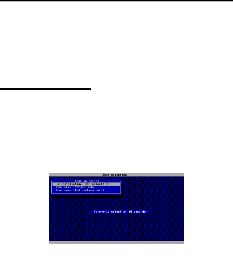
Troubleshooting 8-37
MAINTENANCE TOOLS
The Maintenance Tools is a tool of this product prevention to maintain, and to analyze the trouble.
IMPORTANT: The explanation using the floppy disk drive has been
described in this book. However, the floppy disk drive is not built into
this product. Please use the Flash FDD or USB FDD.
Starting Maintenance Tools
The Maintenance Tools is started according to the following procedure.
1. Turn on peripheral devices and the server in this order.
2. Insert the NEC EXPRESSBUILDER DVD supplied with your server into the optical disk
drive of your server.
3. Press Ctrl, Alt, and Delete to reboot the server from the NEC EXPRESSBUILDER.
(You may also turn off and then on again to reboot the server.)
System boots up displaying Boot selection menu.
IMPORTANT: An initial selection of the menu is "Os installation".
"Os installation" starts by the automatic after the Boot selection menu is
displayed.
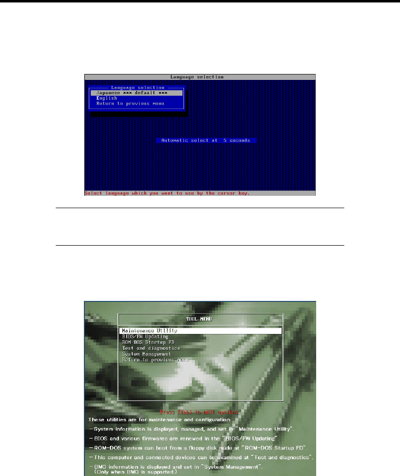
8-38 Troubleshooting
4. When a local console is used, "Tool menu (Normal mode)" is selected.
Moreover, "Tool menu (Redirection mode)" is selected when using it with remote console.
IMPORTANT: An initial selection of the menu is "Japanese".
"Japanese" starts by the automatic operation when the operation is not
done for five seconds after the Language Selection menu is displayed.
5. "English" is selected.
The tool menu is displayed.
When you use a local console
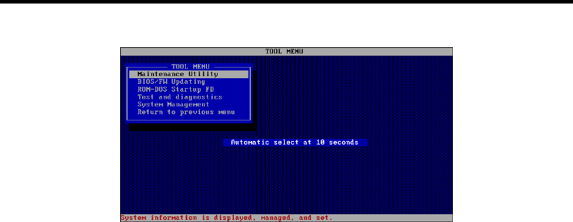
Troubleshooting 8-39
When you use a remote console
6. Each tool is selected, and it starts.

8-40 Troubleshooting
Function of Maintenance Tools
The following functions can be executed in the Maintenance Tools.
Maintenance Utility
The Off-line Maintenance Utility is started in Maintenance Utility. The Off-line
Maintenance Utility is an OS-independent maintenance program. When you are unable to
start the OS-dependent NEC ESMPRO to troubleshoot a problem, the Off-line
Maintenance Utility can be used.
IMPORTANT:
The Off-line Maintenance Utility is intended for use of your service
representative. The NEC EXPRESSBUILDER DVD you have
created contain a file that describes operation of the utility, but do
not attempt to use the utility by yourself. Contact your service
representative and follow instructions.
See the on-line help for details of the Off-line Maintenance Utility.
For further information, ask your service representative.
The Off-line Maintenance Utility provides the following features.
– BIOS Setup Viewer
Provides the functions to export the current configuration data defined with the
SETUP utility to a text file.
– System Information Viewer
Provides the functions to view information on the processor and the BIOS and export
it to a text file.
– System Information Management
Provides the function to make a back-up copy of your data.
Without the backup data, the system-specific information and/or configuration may
not be restored.
Only the authorized personnel is allowed to restore the backup data.
– HWLog Information Viewer
Provides the functions to view information of the HWlog and export it to a text file.

Troubleshooting 8-41
BIOS/FW Updating
This menu allows you to update the software module such as BIOS and firmware of the
server by using the update disk (3.5-inch floppy disk) that is distributed from NEC
customer service representative.
After rebooting the system, an update program is started automatically from floppy disk,
and the various BIOS and firmware programs are updated.
IMPORTANT: Do not turn off the server while the update program is
running. If the update processing is discontinued, the system becomes
unable to start.
ROM-DOS startup FD
Creates a support disk for starting the ROM-DOS system.
Test and diagnostics
Execute various tests on the server system to check if the server functions are normal and
if the connection between the server and additional board is normal.
After the Test and diagnostics is executed, a system check program assigned to each
model starts. See Chapter 7 for details.
System Management
The parameters of BMC (Baseboard Management Controller) are set for remote control
and alert.
This function is not supported in this server.

8-42 Troubleshooting
RESETTING THE SERVER
If the server halts before starting the OS, press and hold Ctrl and Alt and press Delete.
This restarts the server.
Pressing the RESET switch on the front panel reboots the server.
IMPORTANT: Resetting the server clears the DIMM memory and the
data in process. To reset the server when it is not frozen, make sure that
no processing is in progress.
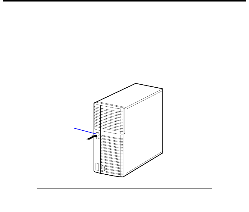
Troubleshooting 8-43
FORCED SHUTDOWN
Use this function when an OS command does not shutdown the server, the POWER/SLEEP switch
does not turn off the server, or RESET button does not work.
Press and hold the POWER/SLEEP switch on the server for at least four seconds. The power is
forcibly turned off. To turn on the power back again, wait approximately 10 seconds after turning
off the power.
IMPORTANT: If the remote power-on function is used, cycle the
power once to load the OS, and turn off the power again in the normal
way.
Press here for at
least 4 seconds.

8-44 Troubleshooting
(This page is intentionally left blank.)

Chapter 9
Upgrading Your Server
This chapter describes internal optional devices available for the server, procedures for install or
removing such optional devices, and notes on using them.
IMPORTANT:
Optional devices described in this chapter may be installed or
removed by any user. However, NEC does not assume any liability
for damage to optional devices or the server or malfunctions of the
server resulted from installation by the user. NEC recommends you
ask your service representative for installing or removing any
optional devices.
Use the options and cables approved by NEC. You will be charged
by any repair of a malfunction, fault, or defect occurring in a server
in which one or more component not approved by NEC are used.
Always update the system if the hardware configuration is changed
(See Chapter 5 for details).
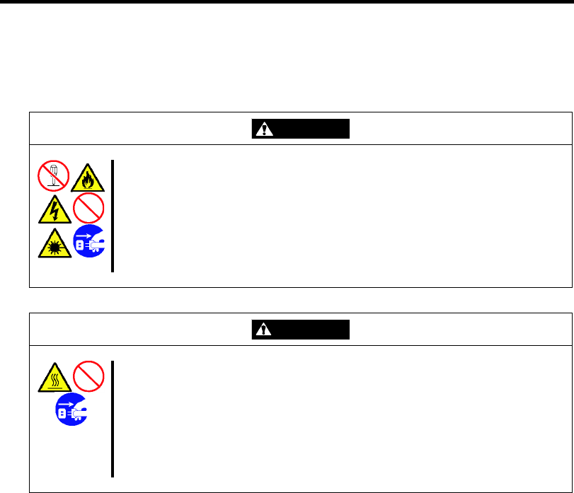
9-2 Upgrading Your Server
SAFETY NOTES
Observe the following notes to install or remove optional devices safely and properly.
WARNING
Observe the following instructions to use the server safely. Failure to follow
these instructions may result in death or serious personal injury. See pages
1-3 to 1-8 for details.
Do not disassemble, repair, or alter the server.
Do not remove the lithium battery.
Disconnect the power plug before working with the server.
CAUTION
Observe the following instructions to use the server safely. Failure to follow
these instructions may cause a fire, personal injury, or property damage. See
pages 1-3 to 1-8 for details.
Avoid installation in extreme temperature conditions.
Make sure to complete board installation.
Protect the unused connectors with the protective cap.
Never attempt to lift the server only by yourself.

Upgrading Your Server 9-3
STATIC PRECAUTIONS
An electrostatic discharge (ESD) can damage disk drives, option boards, and other components.
Electronic device can be easily damaged by static electricity. To prevent damage, observe the
following information.
Wear a wrist strap (an arm belt or anti-static glove).
Wear a wrist strap on your wrist.
Select a suitable work space.
– Work with the server on the anti-static or concrete floor.
– When you work with the server on a carpet where static electricity is likely to be
generated, make sure take anti-static measures beforehand.
Use a work table.
Place the server on an anti-static mat to work with it.
Clothe
– Do not wear a wool or synthetic cloth to work with the server.
– Wear anti-static shoes to work with the server.
– Take off any jewels (a ring, bracelet, or wrist watch) before working with the server.
Handling of components
– Keep any component in an anti-static bag until you actually install it to the server.
– Hold a component by its edge to avoid touching any terminals or components.
– To store or carry any component, place it in an anti-static bag.
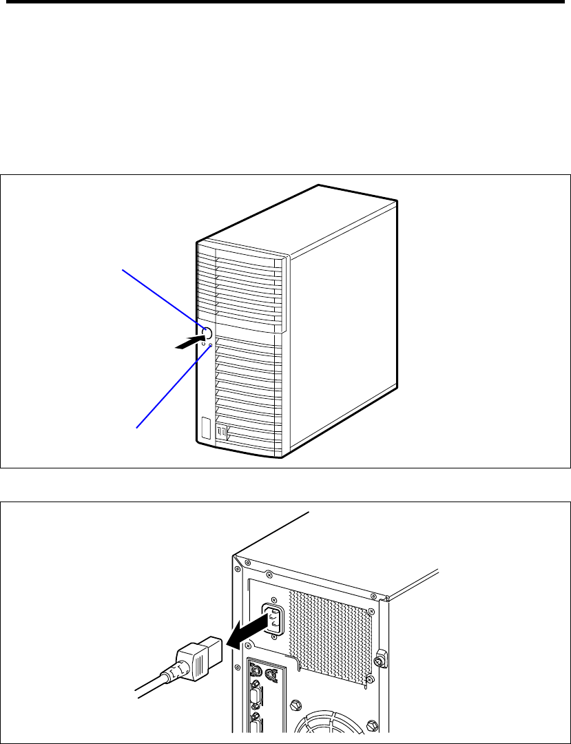
9-4 Upgrading Your Server
PREPARING FOR INSTALLATION AND REMOVAL
Prepare the installation or removal of a component depending on the following procedure:
1. Shut down the OS.
Or, press the POWER/SLEEP switch to turn off the power of the server. (The
POWER/SLEEP lamp goes off.)
2. Pull out the power cord from the AC inlet on the server.
3. Remove all the cables connected to the server on the rear panel.
POWER/SLEEP lamp
POWER/SLEEP switch
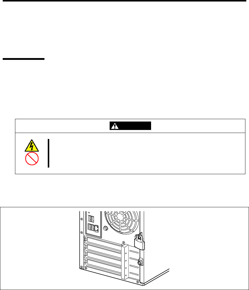
Upgrading Your Server 9-5
INSTALLATION OR REMOVAL PROCEDURE
Install or remove a component from the server in the following procedure.
Side Cover
The side cover should be removed to access to built-in devices and/or mother board in the server.
Removal
Remove the side cover in the following procedure.
WARNING
Observe the following instructions to use the server safely. Failure to follow
these instructions may result in death or serious personal injury. See pages 1-3
to 1-8 for details.
Disconnect the power plug before working with the server.
1. See the section "Preparing for Installation and Removal" described earlier to prepare.
2. Unlock the side cover if required.

9-6 Upgrading Your Server
3. Loosen the two screws.
4. Hold the side cover securely to remove it.
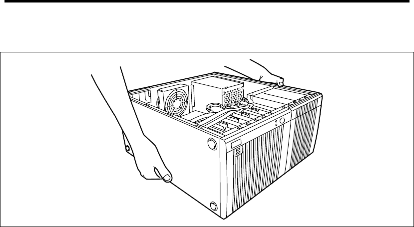
Upgrading Your Server 9-7
5. Slowly and gently lay down the server so that its right side faces the floor.
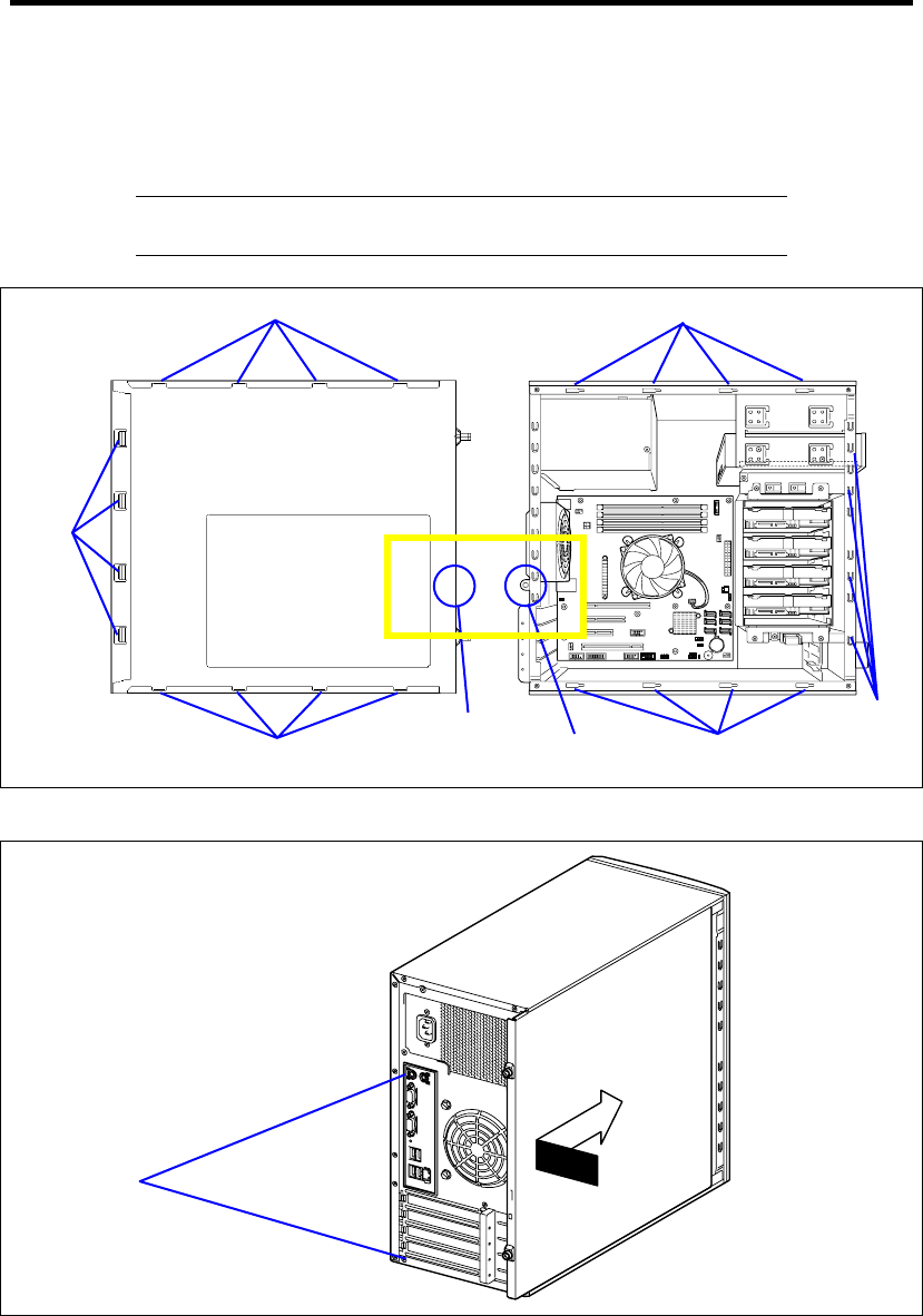
9-8 Upgrading Your Server
Installation
The side cover can be installed in the reverse procedure of the removal. Make sure that the hooks on
the side cover are inserted into the frames and holes of the server securely.
IMPORTANT: After one or more optional devices are installed or
removed completely, install the removed side cover securely.
Secure the side cover with two screws removed in the removal procedure.
デスクトップの表示.scf
Insert a lock
plate here.
Hooks
on front
Hooks on top
Hooks on bottom
Screws
Holes
Frame to
engage
with
hooks
Lock plate
Holes
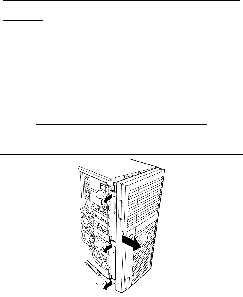
Upgrading Your Server 9-9
Front Bezel
The front bezel must be removed to install or remove the 5.25-inch device and hard disk drive cage.
Removal
Follow the procedure below to remove the front bezel.
1. See the section "Preparing for Installation and Removal" described earlier to prepare.
2. Remove the side cover as described earlier in this chapter.
3. Pull the release tabs (3 places) at the left end of the front bezel toward you (c) so that the
tabs are removed from the frame of the server (d), as shown in the figure below.
IMPORTANT: If the tabs are pulled out toward you excessively, the
hooks fixing the right end of the front bezel will be damaged. Only pull
out the tabs a little.
1
1
1
2
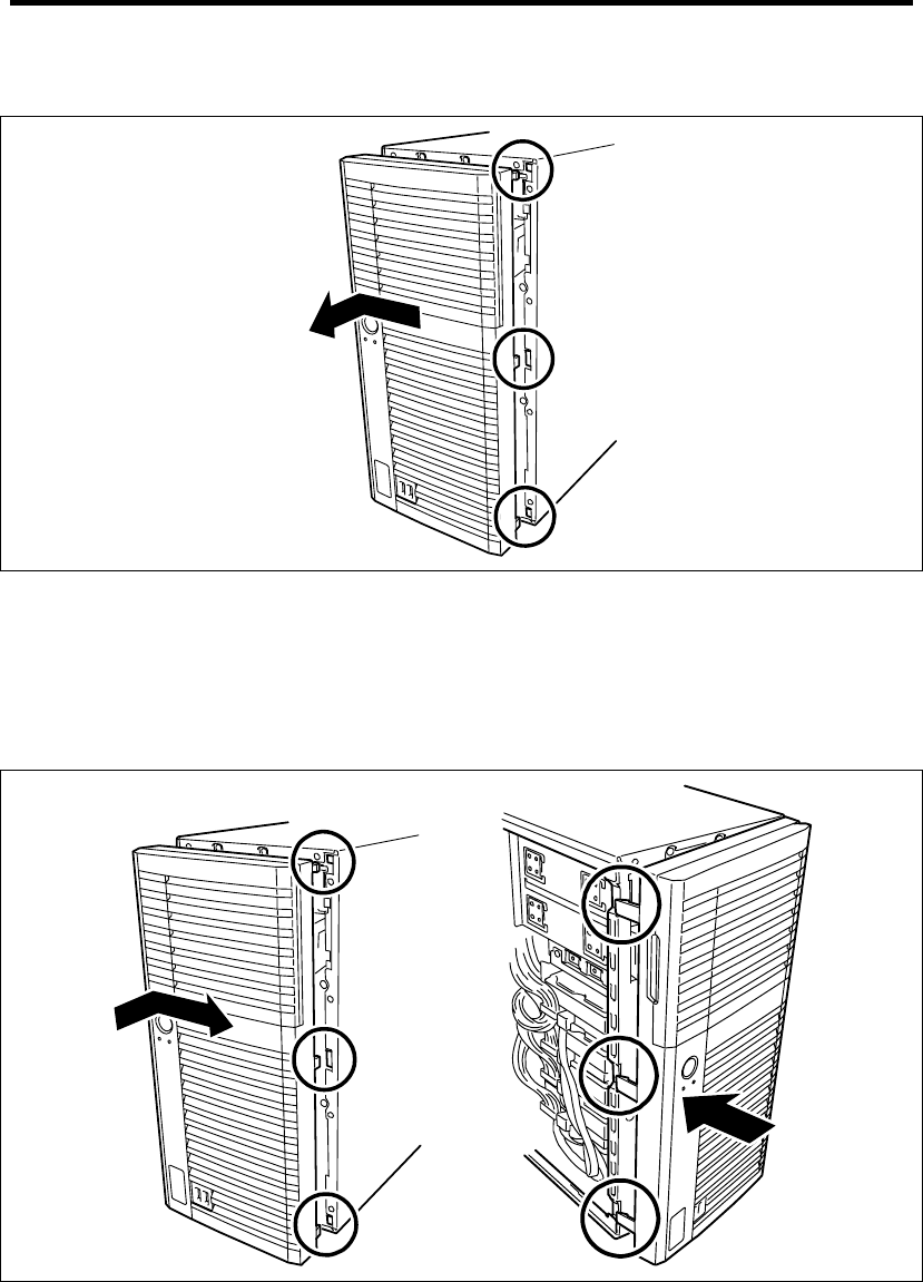
9-10 Upgrading Your Server
4. Remove the front bezel to the left to release the tabs on the front bezel from the server.
Installation
The front bezel can be installed in the reverse order of the removal. Insert the three tabs at the right
end of the front bezel into the holes on the front of the server, press the left end of the front bezel to
the server, and lock the mask with the release tabs.
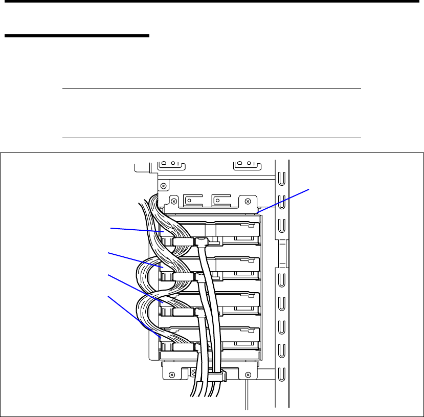
Upgrading Your Server 9-11
3.5-inch Hard Disk Drive
The 3.5-inch Hard Disk drive cage can contain up to four SATA hard disk drives.
IMPORTANT: Do not use any hard disk drive that is not authorized by
NEC. Installing a third-party hard drive may cause a failure in the
server as well as the hard disk drive. Repair of any failure or damage in
the server caused by such a hard disk drive will be charged.
Hard disk drive cage
Hard disk drive (Slot 3)
Hard disk drive (Slot 2)
Hard disk drive (Slot 1)
Hard disk drive (Slot 0)
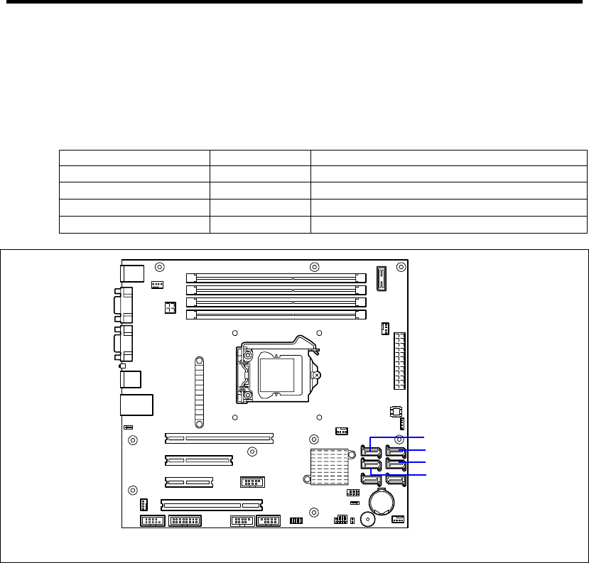
9-12 Upgrading Your Server
Installation
Follow the procedure as described below to install 3.5-inch hard disk drives.
1. Configure the operation mode of hard disk drives according to the manual supplied with
the hard disk drive.
Hard disk drive Cage to Install Serial ATA connector on mother board
First hard disk drive Slot 0 Serial ATA connector 0
Second hard disk drive Slot 1 Serial ATA connector 1
Third hard disk drive Slot 2 Serial ATA connector 2
Fourth hard disk drive Slot 3 Serial ATA connector 3
2. See the section "Preparing for Installation and Removal" described earlier to prepare.
3. Remove the side cover.
4. Disconnect the interface cable and power cable from the hard disk drive if connected.
Serial ATA connector 0
Serial ATA connector 1
Serial ATA connector 3
Serial ATA connector 2
Mother board
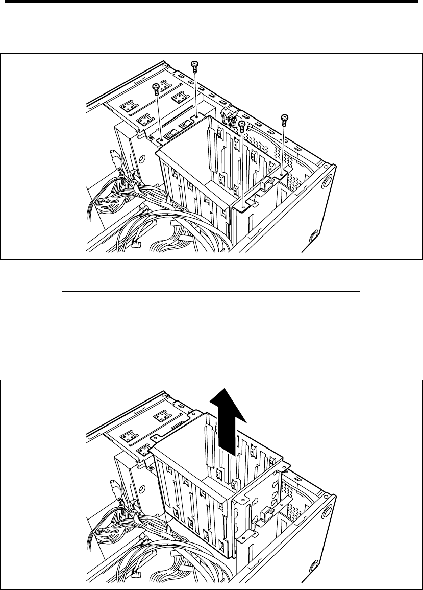
Upgrading Your Server 9-13
5. Remove the four screws securing the hard disk drive cage.
6. Remove the 3.5-inch hard disk drive cage.
IMPORTANT:
Be careful not to have the hard disk drive cage hit on any
components on the mother board.
Be careful not to get the hard disk drive cage caught in internal
cables.
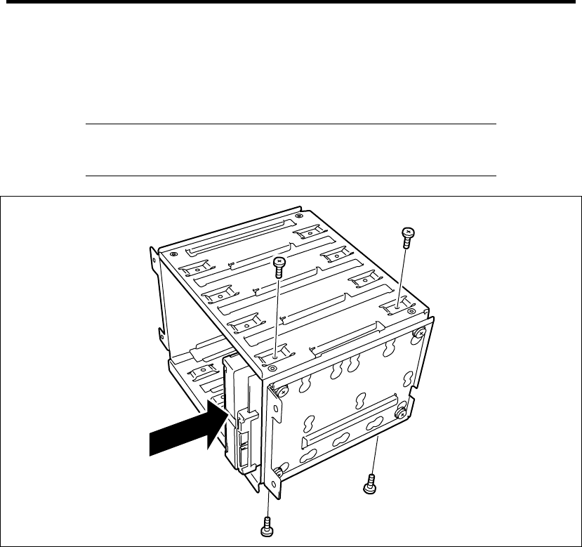
9-14 Upgrading Your Server
7. Place the hard disk drive cage on the anti-static table carefully.
8. Hold the hard disk drive with the connector side facing toward you and the board side
facing downward and then insert the hard disk drive into the slot slowly and gently.
IMPORTANT: Use the screws ("screw set 504") provided with the
server to secure it. Using screws longer than the required length may
cause the hard disk drive to be damaged.
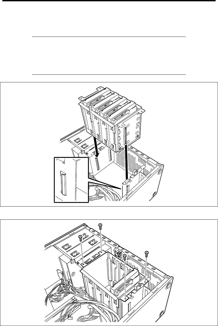
Upgrading Your Server 9-15
9. Align the guide on the support bracket then, insert the hard disk drive cage into the server
carefully.
IMPORTANT:
Be careful not to make the hard disk drive cage hit on any
components on the mother board.
When inserting the cage, be careful not to have the hard disk drive
damage the cables.
10. Secure the hard disk drive cage with the four screws removed in step 5.
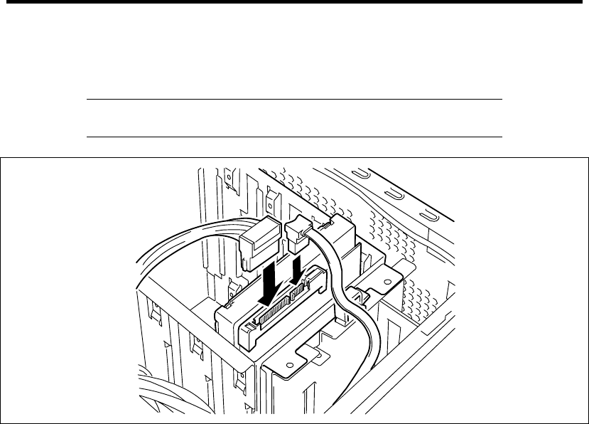
9-16 Upgrading Your Server
11. Connect the interface cable and power cable to the hard disk drive. Connect cables
removed in step 4.
NOTE: Use the red cables for even-numbered ports, and blue cables
for odd-numbered ports.
12. Assemble the server.
13. Run BIOS SETUP utility and check to see that the hard disk drive is correctly recognized.
See Chapter 4 for details.

Upgrading Your Server 9-17
Removal
Follow the procedure as described below to remove 3.5-inch hard disk drives.
IMPORTANT: About data on the hard disk drive
Be sure to take appropriate measures not to leak important data (e.g.,
customers' information or companies' management information) on the
removed hard disk drive to any third parties.
Data seems to be erased when you empty "Recycle Bin" of Windows or
execute the "format" command of the operating system. However, the
actual data remains written on the hard disk drive. Data not erased
completely may be restored by special software and used for
unexpected purposes.
It is strongly recommended that the software or service (both available
at stores) for data erasure should be used in order to avoid the trouble
explained above. For details on data erasure, ask your sales
representative.
1. See the section "Preparing for Installation and Removal" described earlier to prepare.
2. Remove the side cover.
3. Follow Steps 1 through 7 of the installation procedure to remove the disk cage.
4. Follow Steps 8 and 9 of the installation procedure to remove the hard disk drive.
5. Reassemble the server.
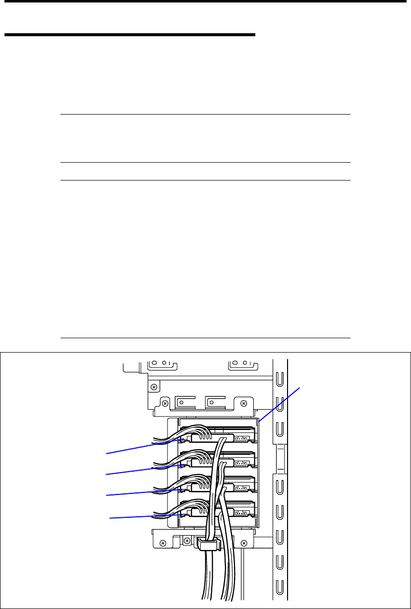
9-18 Upgrading Your Server
2.5-inch Hard Disk Drive Cage (Option)
Your server supports the 2.5-inch Hard Disk Drive Cage as an option.
The 2.5-inch Hard Disk Drive Cage can contain up to four SATA/SAS hard disk drives or SSD
(Solid State Drive).
IMPORTANT: Do not use any hard disk drive or SSD that is not
authorized by NEC. Installing a third-party drives may cause a failure
in the server as well as the drives. Repair of any failure or damage in
the server caused by such drives will be charged.
NOTE: Combining SATA/SAS hard disk drives and SSDs
SATA/SAS hard disk drives and SSDs cannot be combined in BTO
products.
The optional RAID Controller must be used when combining SAS
hard disk drives with SSDs.
Hard disk drives and SSDs cannot be combined within the same
RAID group (pack).
SAS hard disk drives with different rotational speed cannot be
combined.
Install the SATA/SAS hard disk drives in order from slot 0, and then
install the SSDs in the remaining slots.
Hard disk drive cage
Hard disk drive (Slot 3)
Hard disk drive (Slot 2)
Hard disk drive (Slot 1)
Hard disk drive (Slot 0)
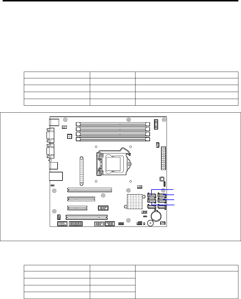
Upgrading Your Server 9-19
Installation
Follow the procedure as described below to install 2.5-inch hard disk drive cage.
1. Configure the operation mode of hard disk drives according to the manual supplied with
the hard disk drive.
<When using the SATA hard disk drive>
Hard disk drive Cage to Install Serial ATA connector on mother board
First hard disk drive Slot 0 Serial ATA connector 0
Second hard disk drive Slot 1 Serial ATA connector 1
Third hard disk drive Slot 2 Serial ATA connector 2
Fourth hard disk drive Slot 3 Serial ATA connector 3
<When using the SAS hard disk drive>
Hard disk drive Cage to Install SAS connector on SAS RAID Controller
First hard disk drive Slot 0
Second hard disk drive Slot 1
Third hard disk drive Slot 2
Fourth hard disk drive Slot 3
SAS RAID Controller
(N8103-109F/116F/117F)
Serial ATA connector 0
Serial ATA connector 1
Serial ATA connector 3
Serial ATA connector 2
Mother board
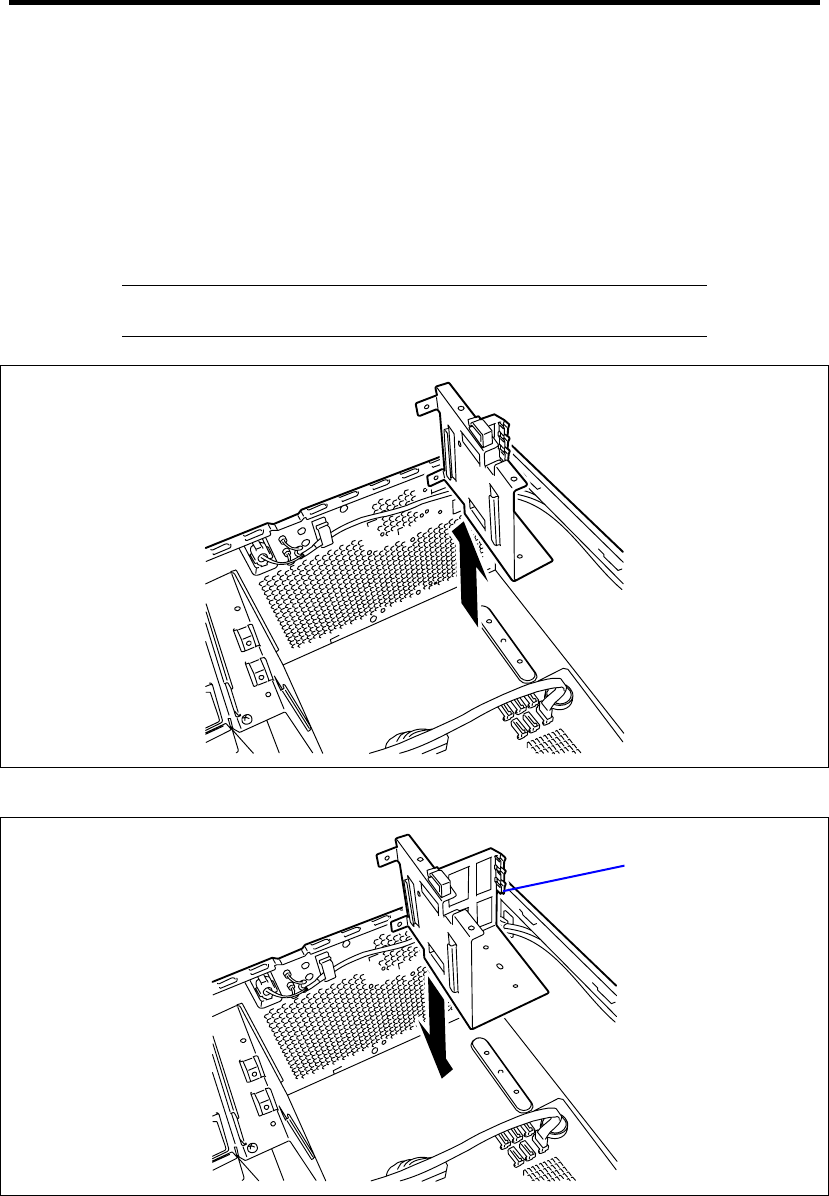
9-20 Upgrading Your Server
2. See the section "Preparing for Installation and Removal" described earlier to prepare.
3. Remove the side cover and front bezel.
4. Remove the 3.5-inch hard disk drive cage.
See the installation procedure of 3.5-inch hard disk drive cage described earlier in this
chapter, perform the reverse to remove the cage.
5. Remove the four screws, then remove the 3.5-inch hard disk drive cage support bracket.
IMPORTANT: Keep the removed 3.5-inch hard disk drive cage and
support bracket for future use.
6. Install the 2.5-inch hard disk drive cage support bracket with four screws.
2.5-inch Hard disk
drive cage support
bracket
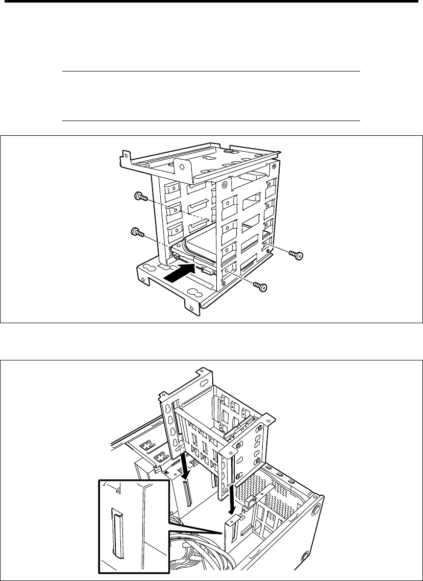
Upgrading Your Server 9-21
7. Hold the 2.5-inch hard disk drive with the connector side facing toward you and the board
side facing downward and then insert the hard disk drive into the slot slowly and gently.
IMPORTANT: Use the screws provided with the hard disk drive. If not,
use the screws provided with the server to secure it. Using screws
longer than the required length may cause the hard disk drive to be
damaged.
8. Align the guide on the chassis then, insert the hard disk drive cage into the server
carefully.
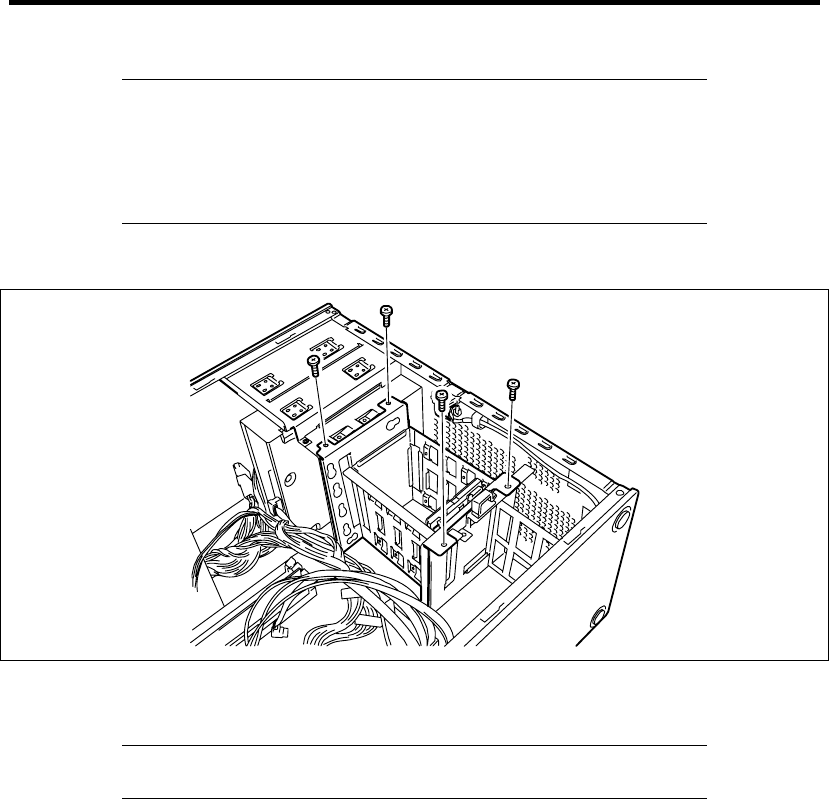
9-22 Upgrading Your Server
IMPORTANT:
Be careful not to make the hard disk drive cage hit on any
components on the mother board.
When inserting the cage, be careful not to have the hard disk drive
damage the cables.
9. Secure the hard disk drive cage with the four screws removed in step 5.
10. Connect the interface cable and power cable to the hard disk drive. Connect cables
removed in Step 4.
NOTE: Use the red cables for even-numbered ports, and blue cables
for odd-numbered ports when using the SATA hard disk drive.
11. Assemble the server.
12. Run BIOS SETUP utility and check to see that the hard disk drive is correctly recognized.
See Chapter 4 for details.

Upgrading Your Server 9-23
Use of Internal Hard Disk Drives in the RAID System
This section describes how to use hard disk drives installed in the cage in the RAID System.
IMPORTANT:
Making hard disk drives in the RAID System or changing the RAID
level initializes hard disk drives. If the hard disk drive to be
configured in the RAID System has your valuable data stored, make
sure to make a backup copy of the data in another hard disk drive
before installing the RAID Controller and configuring the RAID
System.
You can configure a logical drive with a single physical device.
Use hard disk drives of the same capacity and performance (e.g.,
revolution) for each pack to configure them in the RAID System.
NOTES:
Make sure of RAID levels and hard disk drives available for the
RAID Controller to choose an appropriate controller.
A Logical Drive except for RAID0 increases disk reliability.
However, the actually available capacity becomes smaller than the
total hard disk drive capacity in the Logical Drive.
You can build a RAID System by using the Onboard RAID Controller (LSI Embedded
MegaRAID™, software) or optional RAID Controller (N8103-109/116A/117A, hardware).
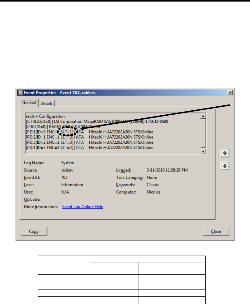
9-24 Upgrading Your Server
The hard disk drive slot number (SLT) that is displayed on the Windows System Event Log or
RAID system management utility screen differs depending on the RAID controller.
The correspondence between the position of each hard disk drive and its slot number (SLT) is
shown below.
Be sure to note this correspondence when referencing a log file or replacing a hard disk drive.
Example of HDD or SSD slot number (SLT) displayed on the Windows System
Event Log
Displayed slot number on the OS screen Slot position in
server unit Onboard RAID
Controller
Optional RAID Controller
(N8103-109/116A)
0 SLT=1 SLT=1
1 SLT=2 SLT=2
2 SLT=3 SLT=3
3 SLT=4 SLT=4
Slot number
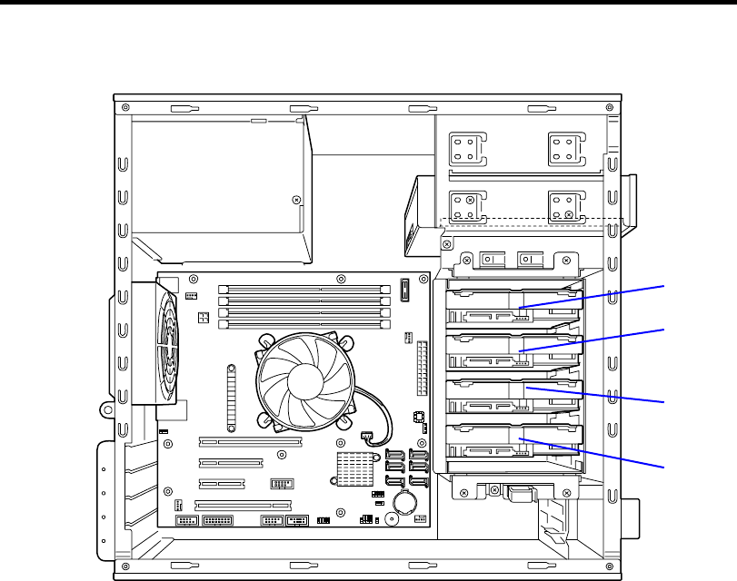
Upgrading Your Server 9-25
Slot position in server unit
0
1
2
3

9-26 Upgrading Your Server
Onboard RAID Controller (LSI Embedded MegaRAID™)
RAID Controller is factory embedded in your mother board. Setting RAID configuration jumper
switch allows internal hard disk drives to be recognized as RAID drives.
Use LSI Software RAID Configuration Utility to configure the RAID System. See Chapter 4 for
details.
Optional RAID Controller (N8103-109/116A/117A)
Your server can include the optional RAID Controller (N8103-109/116A/117A). The optional RAID
Controller can control the internal hard disk drives as the RAID System. When configuring the
internal hard disk drive as a RAID system by installing an optional RAID controller
(N8103-109/116A/117A), use the following optional cable instead of the interface cable supplied
with the server:
When using a 3.5-inch hard disk drive:
K410-221(00) internal SAS cable
When using a 2.5-inch hard disk drive:
K410-220(00) internal SAS cable
At the factory, the interface cable is connected to the serial ATA connector on the mother board.
Refer to the manual coming with optional RAID Controller (N8103-109/116A/117A) for details.
IMPORTANT: The RAID Controller board is extremely sensitive to
static electricity. Make sure to wear the wrist strap (an arm belt or
antistatic glove), and discharge static electricity from your body before
handling the RAID Controller. Do not touch the RAID Controller
terminals or on-board parts by a bare hand or place the RAID
Controller directly on the non-anti-static table. For static notes, see the
section "Static Precautions" described earlier.
NOTE: Before installing an optional RAID Controller, run the SETUP
utility, select [Advanced] → [PCI Configuration], and confirm that
[Enabled] is set for the parameter [PCI Slot x Option ROM] (x: PCI slot
number).
Installation
See "PCI Board" in this chapter and manual that comes with the optional RAID Controller for the
installation of a RAID Controller (N8103-109/116A/117A).
IMPORTANT: When the RAID Controller is connected, the boot
priority specified in BIOS SETUP utility must be eighth or younger. If
specified ninth or later, the configuration menu of RAID Controller will
fail to start.

Upgrading Your Server 9-27
Removal
Remove the optional RAID Controller in reverse order of the installation steps.
Notice
Observe the following notes on configuring a RAID System:
The installed hard disk drives (SAS drives or SATA drives) must the same capacity and
the same rotational speed. (The minimum number of required disks depends on the
configuration of RAID (Redundant Arrays of Inexpensive [Independent] Disks).)
Select/set a RAID level.
Onboard RAID Controller: RAID0, RAID1, or RAID10
Optional RAID Controller: RAID0, RAID1, RAID5, RAID6, or RAID10
When installing a system in an internal hard disk drive, you should use "Express Setup" to perform
all the procedures for RAID System configuration, OS installation, and then OS setup.
Use Express Setup even when not installing a system. Start Express Setup, select [OS Selection]
-[Others]. The installer automatically performs all the procedures for RAID System configuration,
and then maintenance utility installation.
When making the setup in manual mode, use the RAID System configuration utility in the chip on
the board. You can start the utility during execution of POST that automatically starts immediately
after you turn on the POWER/SLEEP switch. For details, see the online document in the NEC
EXPRESSBUILDER DVD provided with the server. For details on the data transfer rate, RAID,
and RAID System configuration, see the manual provided with the RAID Controller as well as the
online document.
IMPORTANT:
When N8103-109/116A/117A is installed, do not let the system
enter hibernation or standby mode.
Configuring RAID System by SATA hard disk drives together with
SAS hard disk drives is not permitted.

9-28 Upgrading Your Server
Additional Battery for Optional RAID Controller
When installing a RAID controller (N8103-109/116A/117A), be sure to use the optional additional
battery to avoid losing data in the unexpected event of a power cut or other serious failure. The
battery to be used differs depending on the RAID controller as follows:
When using an N8103-116A/117A RAID controller:
• N8103-121 additional battery
When using an N8103-109 RAID controller:
• N8103-125 additional battery
Notes on use
Observe the cautions below when using the additional battery. Failure to observe these cautions
might result in damage to property or assets (such as data or other equipment).
Use the additional battery specified for each RAID controller.
The additional battery is a very delicate piece of electronic equipment and is easily damaged.
Before handling the battery, be sure to touch the server frame or other area to discharge any
static electricity from your body.
Do not drop or otherwise subject the additional battery to excessive shock or vibration.
Be sure to read the user's guide supplied with the additional battery before recycling or
disposing of the battery.
Attaching and removing the N8103-121 additional battery
Attaching the battery
1. Attach the connector board and battery control cable supplied with the N8103-121
additional battery to the RAID controller. Refer to the user's guide supplied with the
additional battery for how to attach the connector board and cable to the RAID controller.
2. Prepare the server as shown on Page 9-4.
3. Remove the side cover as shown on Page 9-5.
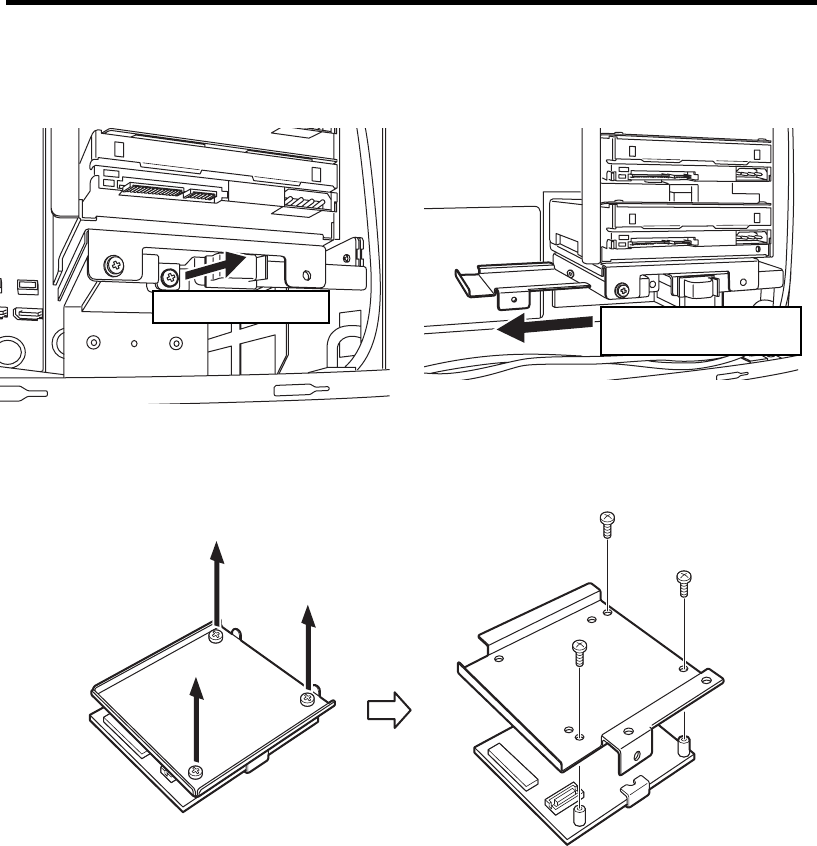
Upgrading Your Server 9-29
4. Remove the anchor plate attached to the bottom of the hard disk drive cage.
5. Remove the three screws that attach the battery pack to the bracket and attach the battery
pack to the plate removed in step 4.
Remove the screw. Slide out the plate in
the direction shown.
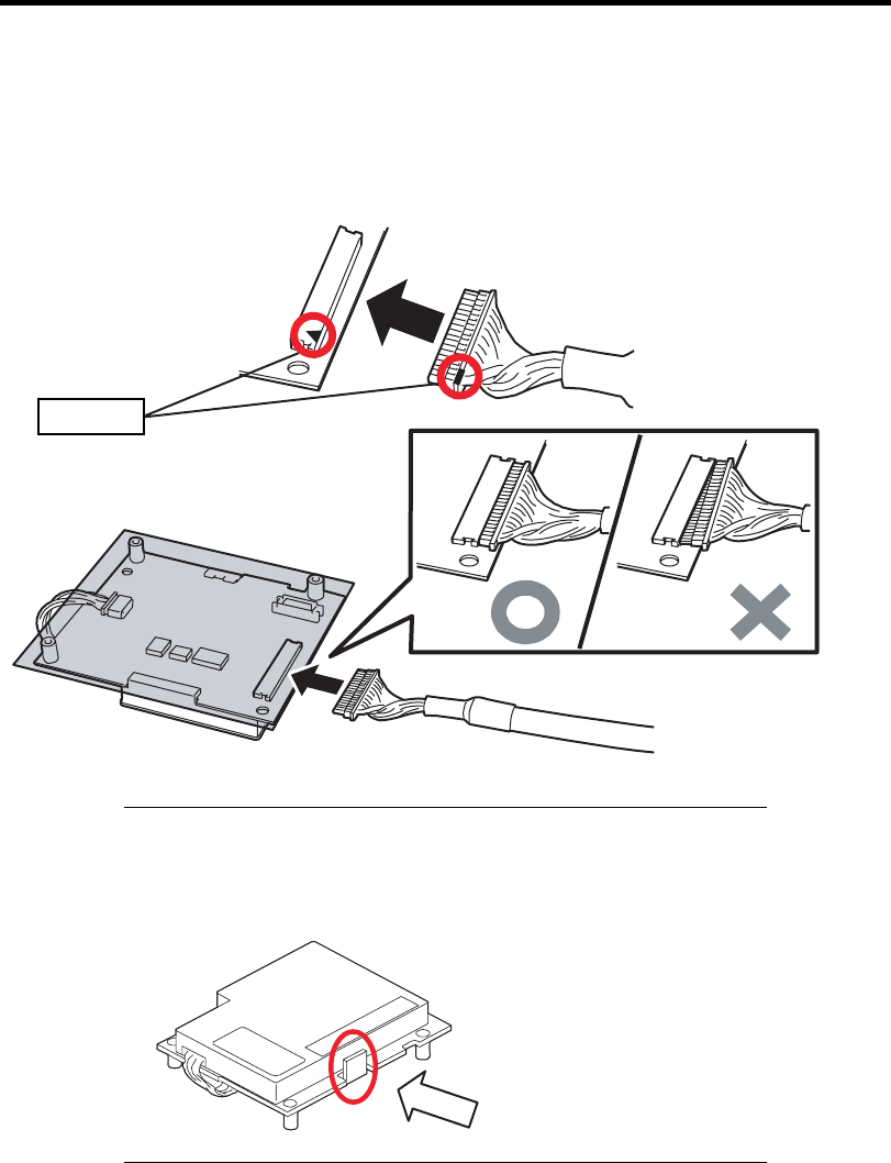
9-30 Upgrading Your Server
マーキング
6. Connect the battery control cable to the battery pack. Make sure that the cable is inserted
firmly and straight into the connector. Do not wriggle the cable head while inserting it.
Correct connection Connect the cable to the connector aligning the markings on each.
IMPORTANT: Do not apply excessive force to the section of the
battery cover indicated in the picture below when attaching it to and
removing it from the server as this may damage the battery pack
components.
Markings
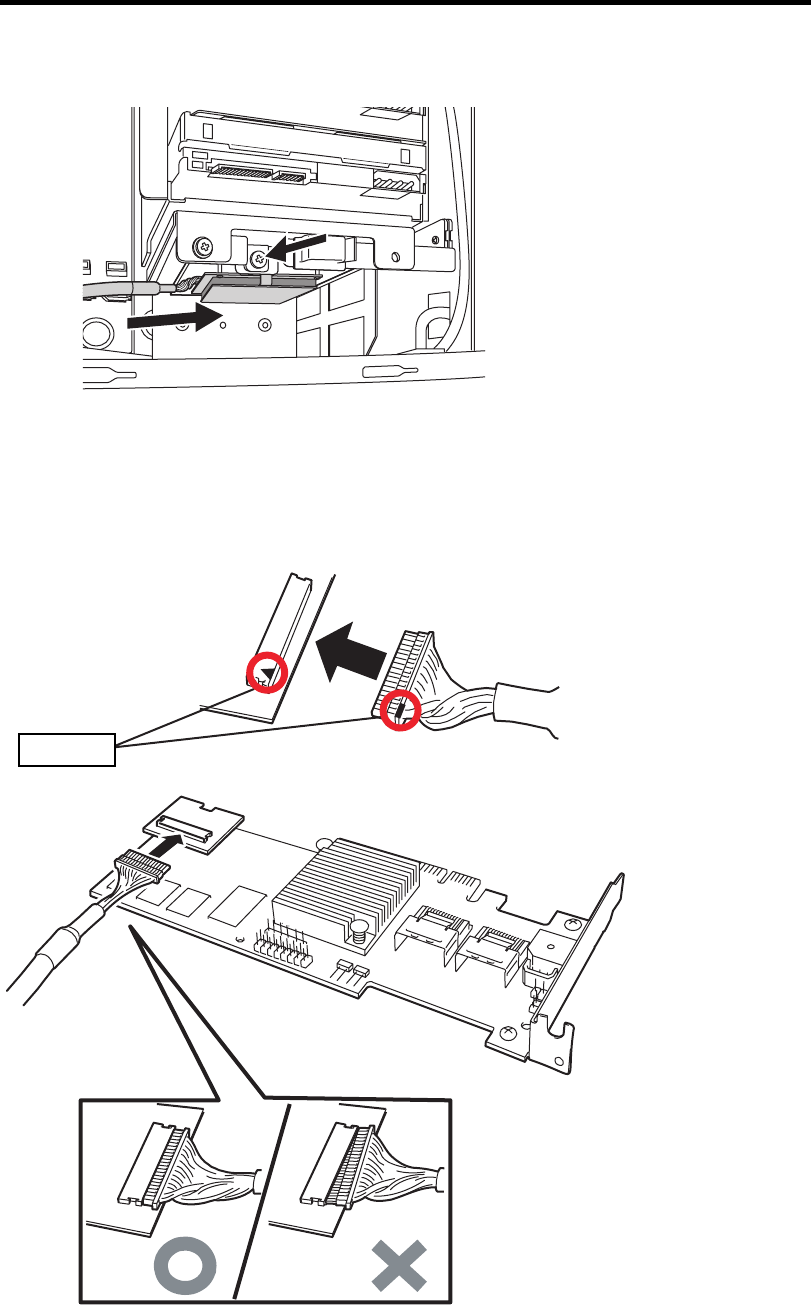
Upgrading Your Server 9-31
マーキング
7. Attach the battery unit to the server using the screw removed in step 4.
8. Attach the other end of the battery control cable to the connector board on the RAID
controller. Make sure that the cable is inserted firmly and straight into the connector. Do
not wriggle the cable head while inserting it.
Correct connection Connect the cable to the connector aligning the markings on each.
Markings
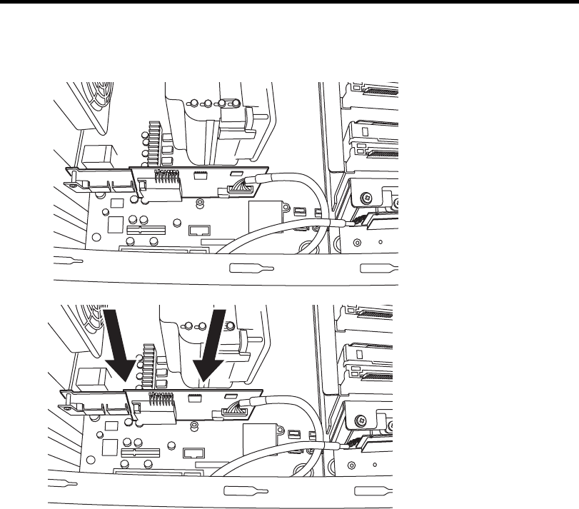
9-32 Upgrading Your Server
9. Insert the RAID controller board into the slot on the motherboard.
10. Reattach the parts of the server removed at the start.
Removing the battery
Remove the battery unit by reversing the above procedure.
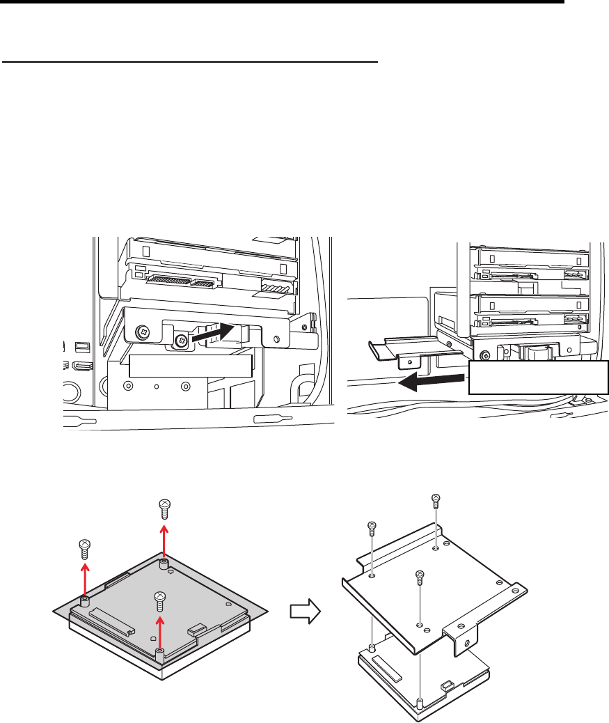
Upgrading Your Server 9-33
Attaching and removing the N8103-125 additional battery
Attaching the battery
1. Attach the connector board and battery control cable supplied with the N8103-125
additional battery to the RAID controller. Refer to the user's guide supplied with the
additional battery for how to attach the connector board and cable to the RAID controller.
2. Prepare the server as shown on Page 9-4.
3. Remove the side cover as shown on Page 9-5.
4. Remove the anchor plate attached to the bottom of the hard disk drive cage.
5. Remove the three screws that attach the battery pack to the bracket and attach the battery
pack to the plate removed in step 4.
Remove the screw. Slide out the plate in
the direction shown.

9-34 Upgrading Your Server
バッテリのプレートが上面となる状態で…
左端に青い線
表面にドット無し
6. Connect the remote battery control cable to the battery pack.
7. Attach the battery unit to the server using the screw removed in step 4.
Turn the battery pack over so that the plate is on the top.
The blue wire is on
the left.
No dot on the top
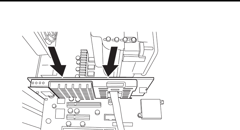
Upgrading Your Server 9-35
8. Insert the RAID controller board into the slot on the motherboard.
9. Reattach the parts of the server removed at the start.
Removing the battery
Remove the battery unit by reversing the above procedure.
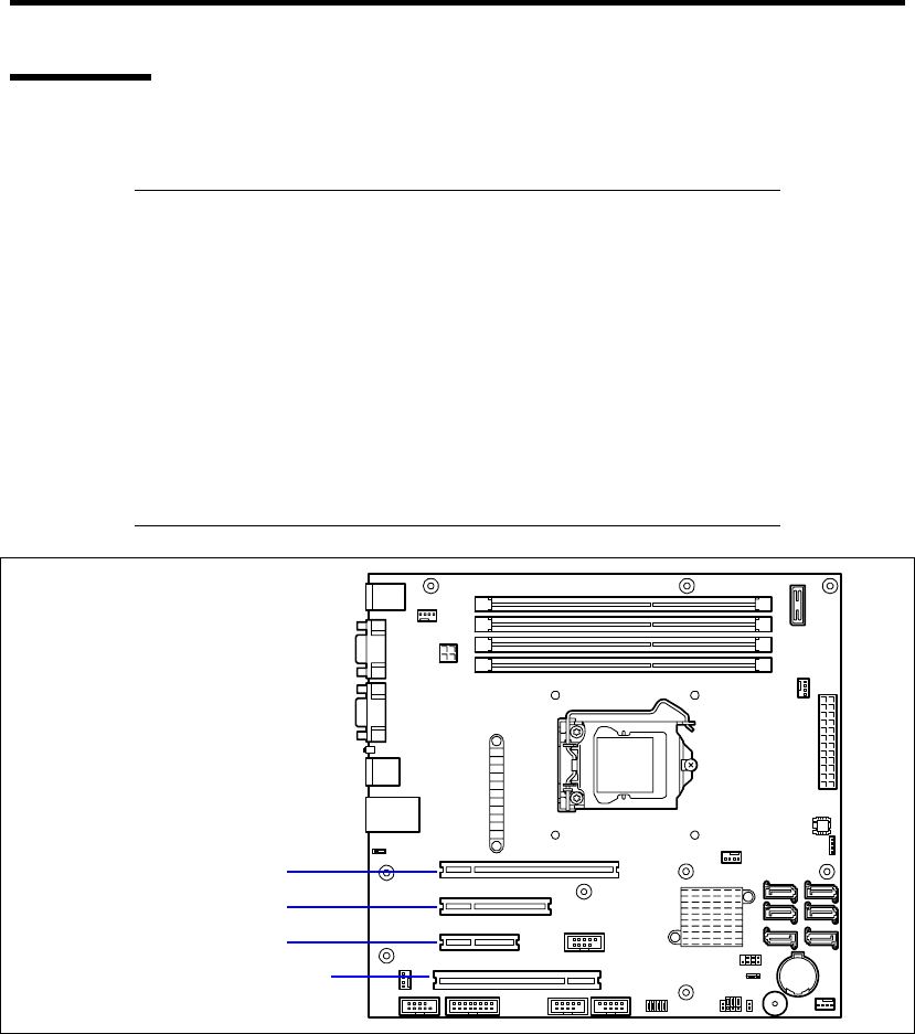
9-36 Upgrading Your Server
PCI Board
The server is equipped with five slots for installing PCI boards.
IMPORTANT:
Any PCI board is easily affected by static electricity. Make sure to
wear the wrist strap (an arm belt or anti-static glove), and discharge
static electricity from your body before handling the PCI board. Do
not make bare hands contact with terminals and components on the
PCI board. In addition, do not put the PCI board on a non-anti-static
desk directly. See "Static Precautions" in this chapter for details of
the static electricity.
The long-sized board (full-length board) can be installed only to the
PCI slots #4. Care must be taken to avoid damage to the
components on the mother board when installing the long-sized
board.
PCI slot #1 (PCI EXPRESS x16)
PCI slot #2 (PCI EXPRESS x4)
PCI slot #3 (PCI EXPRESS x2)
PCI slot #4 (PCI 32-bit/33 MHz)

Upgrading Your Server 9-37
Slots to install the PCI board
Product name PCI #1 PCI #2 PCI #3 PCI #4
PCI slot capability(*3) x16 lane x4 lane x2 lane 32-bit/
33MHz
Slot size Full-height
PCI board type x16
socket
x8
socket
x4
socket 5V
N code
Available board size Short Short Long
Remarks
N8103-95 SCSI controller
(64-bit/66MHz PCI) – – –
√ –
N8103-75 SCSI controller
(64-bit/133MHz PCI-X) – – –
√ Cannot co-exist with N8103-107.
N8103-107 SCSI controller
(PCI EXPRESS (x1)) – √ √ – Cannot co-exist with N8103-75.
N8103-104A SAS controller
(PCI EXPRESS(x8)) √ √ √ – Cannot connect to internal HDD.
N8103-142 SAS controller
(PCI EXPRESS(x8)) √ √ √ –
N8103-109
RAID Controller
(128MB, RAID 0/1/5/6)
(PCI EXPRESS (x8))
√ √ – – –
N8103-116A
RAID Controller
(128MB, RAID 0/1)
(PCI EXPRESS (x8))
√ √ – – –
N8103-117A
RAID Controller
(128MB, RAID 0/1/5/6)
(PCI EXPRESS (x8))
√ √ – – –
N8104-111 100BASE-TX adapter
(32-bit/33MHz PCI) – – –
√ –
N8104-119 1000BASE-T adapter
(64-bit/133MHz PCI-X) – – –
√
N8104-120 1000BASE-T adapter (2 ch)
(64-bit/133MHz PCI-X) – – –
√
Teaming with another NIC (FEC/GEC)
is not allowed.
N8104-126 1000BASE-T adapter
(PCI EXPRESS (x1)) √ √ √ –
Teaming with an identical AFT/ALB is
possible when using a standard
network with the following optional
LAN boards.
N8104-121 1000BASE-T adapter (2ch)
(PCI EXPRESS (x4)) √ √ √ –
Teaming with another N8104-121 is
allowed.
Teaming with any other NIC is not
allowed.
Cannot co-exist with N8104-112.
N8104-125A 1000BASE-T adapter (4ch)
(PCI EXPRESS (x4)) √ √ √ –
1 max.
Cannot co-exist with N8103-110/120.
Teaming with any other NIC is not
allowed.
Cannot co-exist with N8104-112.
N8104-112 1000BASE-SX adapter (2ch)
(64-bit/133MHz PCI-X) – – –
√
1 max.
Cannot co-exist with
N8104-119/126/120/121/125.
N8117-01A Additional RS232C
connector kit √ √ √ √ 1 max.
√: Available, –: Unavailable
*1 Lane: Indicates the transfer capability (transfer bandwidth). Example: 1 lane = 2.5 Gbps
(unidirectional), 4 lanes = 10 Gbps (unidirectional)
Socket: Indicates the connector size. A card that has the socket number or less can be connected.
Example: For a x4 socket, a x1 card or x4 card can be inserted. A x8 card cannot be inserted.
*2 The N8117-01A additional RS-232C connector kit comes with two types of cables. This
equipment uses "RS-232C cable (B)".
*3 Boards that are up to 173.1 mm long can be inserted into PCI slots 1, 2, and 3, and boards that
are up to 312 mm long can be inserted into PCI slot 4.

9-38 Upgrading Your Server
The card capability enclosed in parentheses after each product name indicates the maximum
operating capability of the card itself.
Even if the operating capability of a PCI card exceeds that of the PCI slot, the card operates at the
slot capability.
Standard network
Teaming with an identical AFT/ALB is possible when using a standard network with the following
optional LAN boards:
N8104-126, N8104-121, N8104-125A
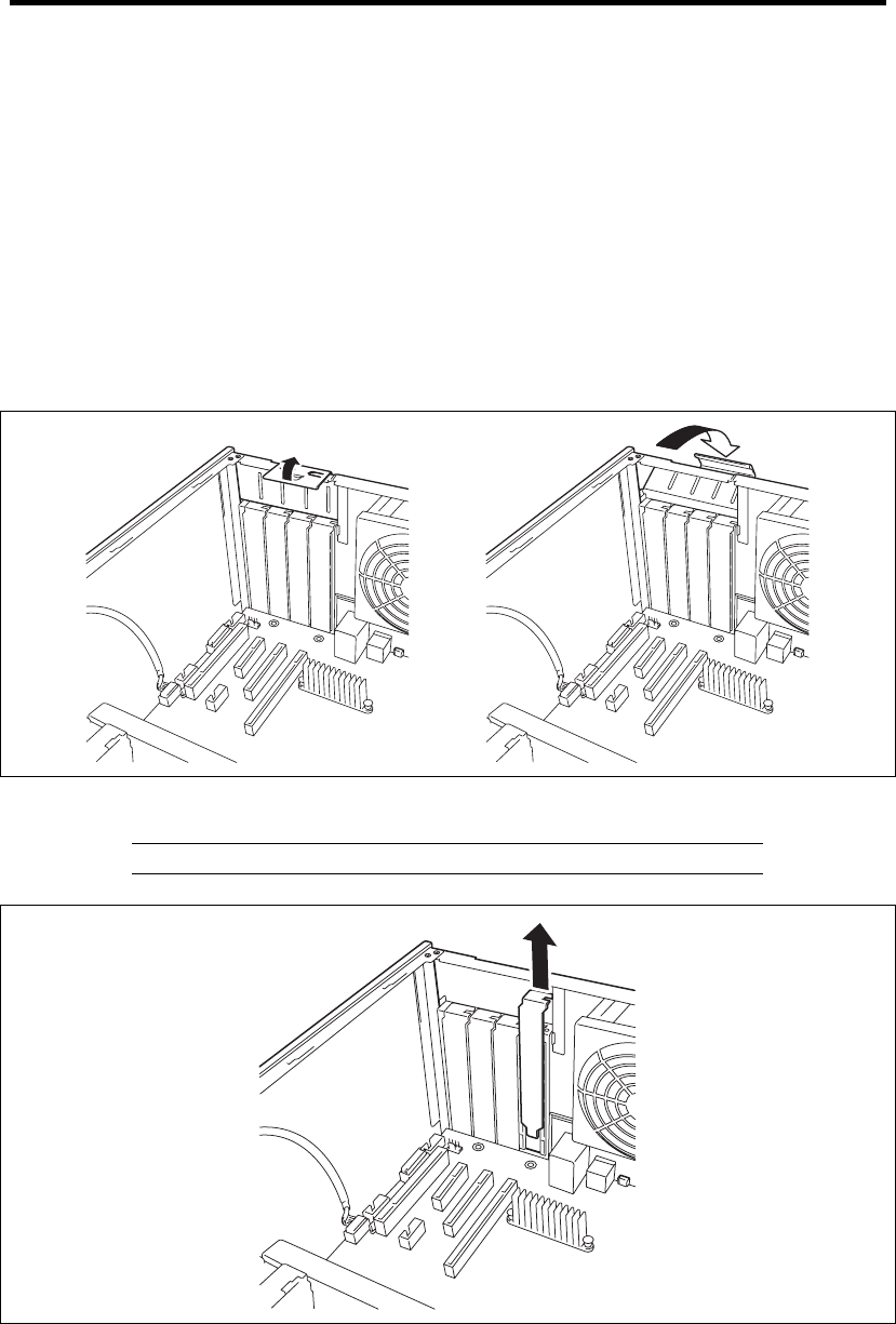
Upgrading Your Server 9-39
Installation
Install the board to be connected to the PCI board slot depending on the following procedure. Refer
to the manual provided with the board.
1. Before the installation, set the switches and jumpers on the installed board appropriately
referring to the manual provided with the board, if necessary.
2. See the section "Preparing for Installation and Removal" described earlier to prepare.
3. Remove the side cover.
4. Lift the tab of the PCI board retention springs to release the lock.
Then, open the PCI board retention spring.
5. Remove the additional slot cover.
IMPORTANT: Save the removed slot cover carefully.
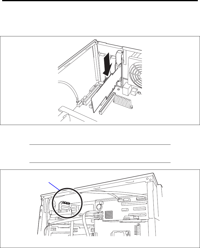
9-40 Upgrading Your Server
6. Make the component side of the board face the bottom of the server, put the rear panel of
the board on the frame spring securely, and push the board fully so that the board
connection port is certainly connected to the slot.
For a long-sized board, align the board with the groove of the guide rail on the front of the
server and then connect the board to the slot.
IMPORTANT: If the board cannot be installed well, remove the board
once and then install it again. Note that adding an excess force to the
board may cause it to be damaged.
PCI guide rail
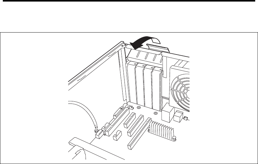
Upgrading Your Server 9-41
7. Close the PCI retention springs. A click occurs to lock the tabs.
8. Assemble the server.
9. Turn on the power of the server. Make sure that no error message appears in the POST.
If an error message appears, write down the message and contact your maintenance
service representative for the maintenance.

9-42 Upgrading Your Server
Setting after installation
Depending on the type of the installed board, some settings of the server must be modified by using
the proper utility (such as the BIOS Setup Utility or the setup utility installed in the board) after the
installation.
Provide the settings correctly according to the information described in the manual provided with
the board.
The server scans the PCI bus numbers in the ascending order after the power-on. If the BIOS utility
is stored in the optional ROM mounted on the board, the PCI bus start messages (banners) appear in
the ascending order of the PCI bus numbers.
Removal
Remove the board connected to the PCI board slot in the following procedure.
1. See the section "Preparing for Installation and Removal" described earlier to prepare.
2. Remove the side cover.
3. Open the PCI board retention springs following the installation steps 4.
4. Remove the board.
5. Install the additional slot cover and then close the PCI board retention springs following
the installation steps 7.
6. Assemble the server.
7. Turn on the power of the server. Make sure that no error message appears in the POST.
If an error message appears, write down the message and contact your service
representative for the maintenance.
8. Run the BIOS Setup Utility to set the "Reset Configuration Data" in the "Advanced"
menu to "Yes."
This is required to update the hardware configuration information. See Chapter 4 for
details.
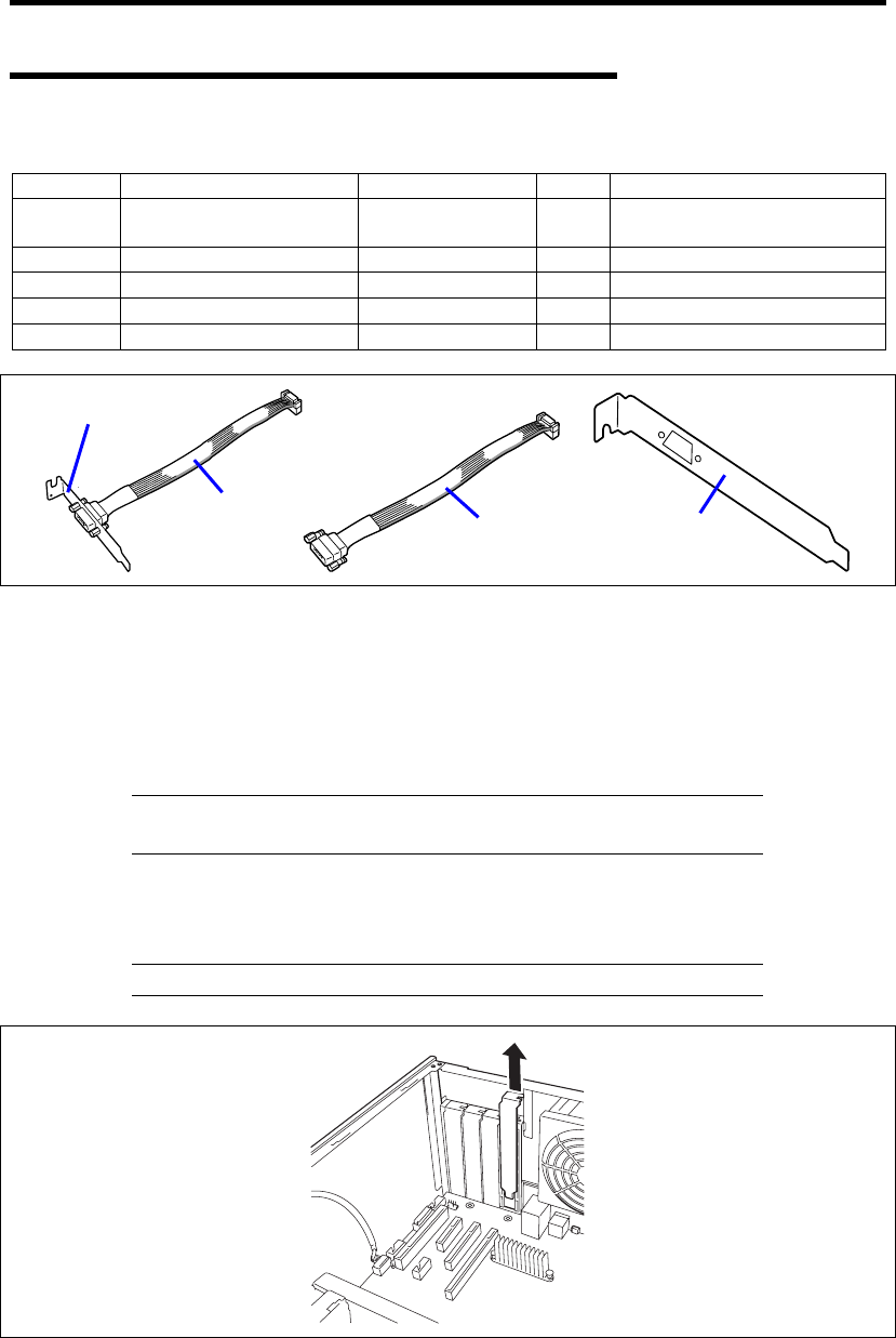
Upgrading Your Server 9-43
Installation of N8117-01A RS-232C Connector Kit
The shipping carton contains the following components.
Item No. Name Specification No. Q'ty Remarks
1 RS-232C Connector Kit
Handling Guide
856-125671-002 1
2 RS-232C cable (A) 804-063264-020 1
3 RS-232C cable (B) 804-062746-820 1
4 PCI bracket (1) 243-112122-001 1 Attached to the cable
5 PCI bracket (2) 243-112122-002 1 For Full Height PCI board
Use Item No. 3 (RS-232C cable (B)) and No. 5 (PCI bracket (2)).
Install N8117-01A in the following procedure.
1. See the section "Preparing for Installation and Removal" described earlier to prepare.
2. Remove the side cover.
3. Assemble the RS232C cable (B) with the PCI bracket (2).
NOTE: Two types of connectors are provided with N8117-01A
RS-232C Connector Kit. Use "RS232C cable (B)" for the server.
4. Remove the additional slot cover at the same location (height) as the installation slot.
5. Open the PCI board retention spring, then remove the additional slot cover.
IMPORTANT: Save the removed slot cover carefully.
4
2
35
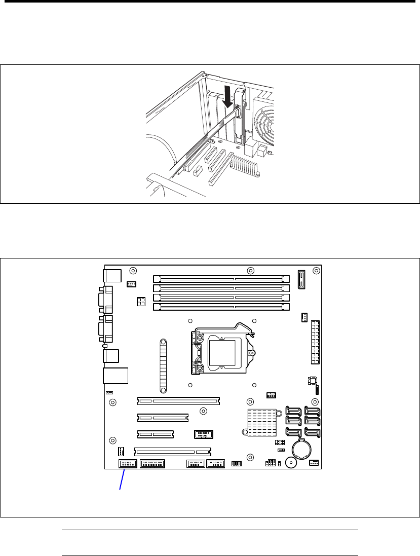
9-44 Upgrading Your Server
6. Install the bracket securely by making sure that the end of the bracket is inserted into the
frame guide of the server.
7. Route the cable so that it does not interfere with the other PCI board, and connect the
cable to the internal COM connector on mother board.
See the figure below for connector location.
IMPORTANT: Connect the cable properly by making sure the polarity
of connector.
8. Make sure that the removed slot cover, screw, or tools are not left in the server.
Then, reassemble the server.
Internal COM connector
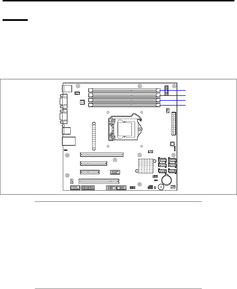
Upgrading Your Server 9-45
DIMM
The DIMM (Dual Inline Memory Module) is installed in a DIMM socket on the mother board
installed in the server.
The mother board contains four sockets in which DIMMs are installed. A 1GB DIMM is factory
installed in DIMM #1. (The DIMMs factory installed may be replaced.)
Up to 16GB (4GB × 4) of memory can be added.
IMPORTANT:
The DIMM is easily affected by static electricity. Make sure to wear
the wrist strap (an arm belt or anti-static glove), and discharge static
electricity from your body before handling the DIMM. Do not make
bare hands contact with terminals and components on the DIMM. In
addition, do not put the DIMM on a non-anti-static desk directly.
See "Static Precautions" for details of the static electricity.
Do not use any DIMM not approved by NEC. If an unapproved
third party's DIMM is installed in the server, not only the DIMM but
also the server itself may be defected. You will be charged by any
repair of a malfunction or defect caused by such a device within the
warranty period.
The mother board in your server supports the single channel memory configuration and dual
channel memory configuration.
The dual channel memory configuration provides increased performance over the single channel
memory configuration
DIMM #2
DIMM #4
DIMM #1
DIMM #3
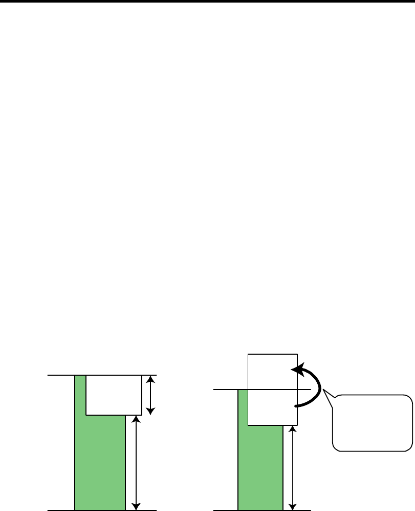
9-46 Upgrading Your Server
Maximum Memory Capacity
The available memory capacity depends on the basic architecture of the server (x86 architecture)
and specifications of supported operating systems.
Memory hole
– The x86 architecture (IA-32) adopts Memory Mapped I/O method which reserves the
fixed memory area (memory hole) for controlling various I/O devices (e.g., onboard
device and PCI devices).
– The memory hole reserves 4GB or less physical memory area as reserved memory area,
regardless of mounted memory capacity. The OS cannot access this reserved area, thus,
the available memory capacity may be less than the actual mounted memory capacity
due to the memory hole.
Memory Reclaim feature
– The server provides Memory Reclaim feature for complementation of memory hole.
– The Memory Reclaim feature remaps physical memory addresses in the memory hole
on hardware (chipset). By remapping, the whole capacity of mounted memory can be
used.
– Note, however, the remap memory area may not be available depending on the memory
capacity supported by OS. Accordingly, the available memory capacity depends on the
supported OS.
Memory hole
(with physical 4GB memory installed)
Memory Reclaim feature
(with physical 4GB memory installed)
Note: When the OS support memory can support the
total capacity of physical memory and memory
hole.
Memory
hole
Memory capacity
available for OS:
A
pprox. 3.3GB
Memory capacity
unavailable for
OS: (Approx.
700MB)
Physical
memory:
4GB
Physical
memory
Physical
memory:
0GB
Memory
hole
Remap
memory
Memory capacity
unavailable for OS:
(Approx. 700MB)
Memory capacity
available for OS:
A
pprox. 3.3GB
Physical
memory
Physical
memory:
0GB
Physical
memory:
4GB
Remaps physical
memory in the memory
hole on hardware.
The OS can use whole
physical memory
mounted.

Upgrading Your Server 9-47
Maximum memory capacity by supported OS
Supported OS
Maximum
memory capacity
supported by OS
Maximum memory capacity
supported by the server
When using HW-DEP feature
(factory default): 4GB
Microsoft Windows Server 2008,
Standard Edition
Microsoft Windows Server 2003
R2, Standard Edition
4GB
When not using HW-DEP feature:
Approx. 3.3GB
Note: If HW-DEP feature is not
used, change [Execute
Disable Bit (XD Bit)] to
"Disabled" on BIOS SETUP.
The factory-setting of this
parameter is "Enabled".
Microsoft Windows Server 2003
R2, Standard x64 Edition
Microsoft Windows Server 2008,
Standard x64 Edition
Microsoft Windows Server 2008
R2, Standard Edition
32GB 16GB
Installation Order and Notes
Single channel memory configuration
Install DIMMs one by one in the ascending order of DIMM slot numbers.
Dual channel memory configuration
To activate the dual channel mode, the following conditions must be met:
– Matched DIMM configuration in each channel
– Same density*
– Same DRAM technology*
– Same DRAM bus width*
– All either single-sided or dual-sided
– Matched in both channels.
– Populate symmetrical memory slots (#1 and #2, #3 and #4).
The following table lists an example of the relationship between the installation condition
and the dual channel memory mode.
Installation
example
Dual channel
memory mode Slot #1 Slot #2 Slot #3 Slot #4
1 Active 1GB
(factory-installed 1GB None None
2 Active 1GB
(factory-installed 1GB 2GB 2GB
3 Inactive 1GB
(factory-installed None None None
4 Inactive 1GB
(factory-installed 1GB 1GB None
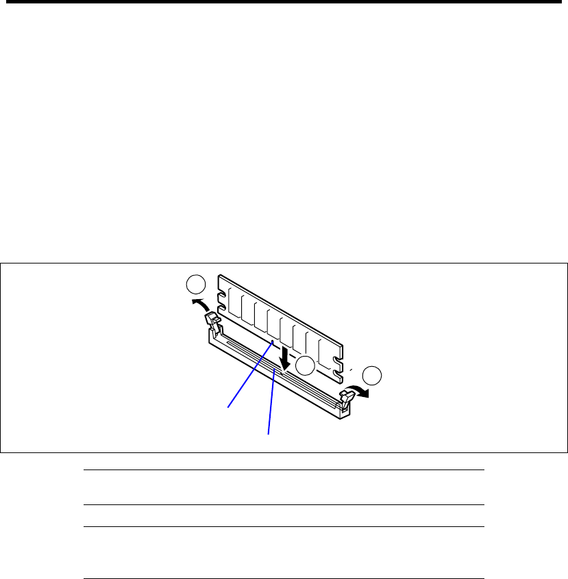
9-48 Upgrading Your Server
Installation
Install a DIMM in the following procedure.
1. See the section "Preparing for Installation and Removal" described earlier to prepare.
2. Remove the side cover as described earlier in this chapter.
3. Firmly hold the server with your both hands so that its left side faces upward, and bring it
down slowly and gently.
4. Open the levers at both ends of the socket (c).
5. Push the DIMM to the socket straight (d).
If the DIMM is inserted into the DIMM socket, the lever is automatically closed.
1
1
2
IMPORTANT: To avoid damaging the lever, do not apply an excess
force to the lever.
NOTE: Use extreme care when installing a DIMM. Applying too
much pressure can damage the socket. Keyed DIMMs insert only one
way.
6. Close the lever securely.
7. Install the remove components.
8. Turn on the power of the server. Make sure that no error message appears in the POST.
If an error message appears, write down the message and contact your service
representative for the maintenance.
9. Run BIOS SETUP utility and check to see that the installed DIMMs are correctly
recognized. See Chapter 4 for details.
10. Run BIOS SETUP Utility to set the "Reset Configuration Data" in the "Advanced" menu
to "Yes." This is required to update the hardware configuration information. See Chapter 4
for details.
11. Set the paging file size to the recommended value or larger. See Chapter 5 for details.
Key slot
Key

Upgrading Your Server 9-49
Removal
Remove the DIMM depending on the following procedure.
NOTES:
To remove the defected DIMM, check the error message appearing
in POST or NEC ESMPRO to identify the DIMM socket (group) in
which the defected DIMM is installed.
The server needs at least one DIMM installed to operate.
1. See the section "Preparing for Installation and Removal" described earlier to prepare.
2. Open the levers at the both ends of the socket for the DIMM to be removed (c).
The lock is released to allow the DIMM to be removed
2
1
1
3. Remove the DIMM (d).
4. Assemble the server.
5. Turn on the power of the server. Make sure that no error message appears in the POST.
If POST displays an error message, take a note on the message and see the POST error
messages listed in Chapter 8.
6. Select "Yes" for [Reset Configuration Data] on the [Advanced] menu.
This is required to update the hardware configuration information. See Chapter 4 for
details.
7. Run the BIOS SETUP and select [Advanced] → [Memory Configuration] → [Memory
Retest] → [Enabled] to clear the error information of the removed DIMM. (See Chapter 4
for details.)
8. Set the paging file size to the recommended value or larger. See Chapter 5 for details.
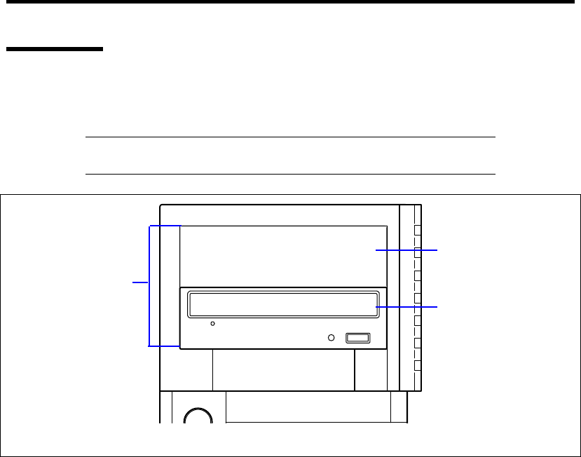
9-50 Upgrading Your Server
File Device
The server has two 5.25-inch device slots on which backup devices including DVD-RAM, MO, and
magnetic tape drives are installed (the factory installed optical disk drive occupies the bottom slot).
NOTE: According to the installed device, the optional controller board
and internal cable are required. See Chapter 10 for details.
A
dditional slot
Optical disk drive
5.25-inch device slot
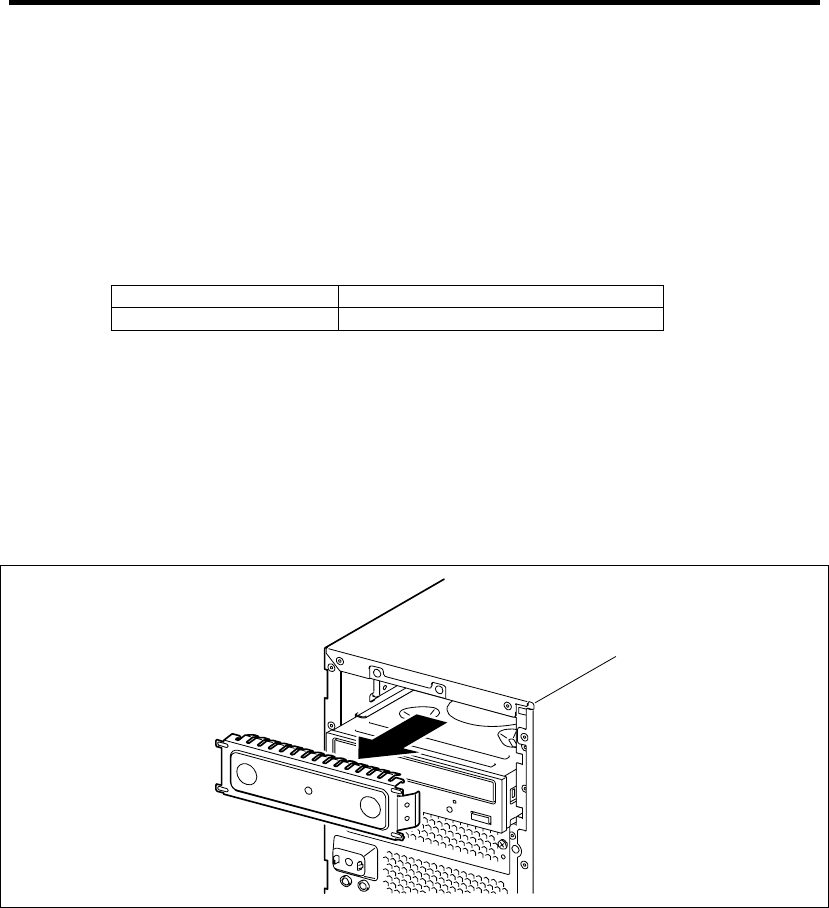
Upgrading Your Server 9-51
5.25-inch Device
Installation
Install a file device in the following procedure. This section describes how to install an optional
SCSI device, for an example:
1. Provide the proper setting for the device.
See the table below for the settings of the devices which can be installed in the device bay.
Device Settings
SCSI device Termination resistance OFF*
* If the terminator is not attached to the optional internal SCSI cable, set the termination
resistance to ON. When installing a SCSI device, make sure that the settings of the
installed SCSI device are not the same as those of an external SCSI device with the
same SCSI ID connected to the controller.
2. See the section "Preparing for Installation and Removal" described earlier to prepare.
3. Remove the side cover and front bezel as described earlier in this chapter.
4. Remove the EMI cover for the 5.25-inch device slot.
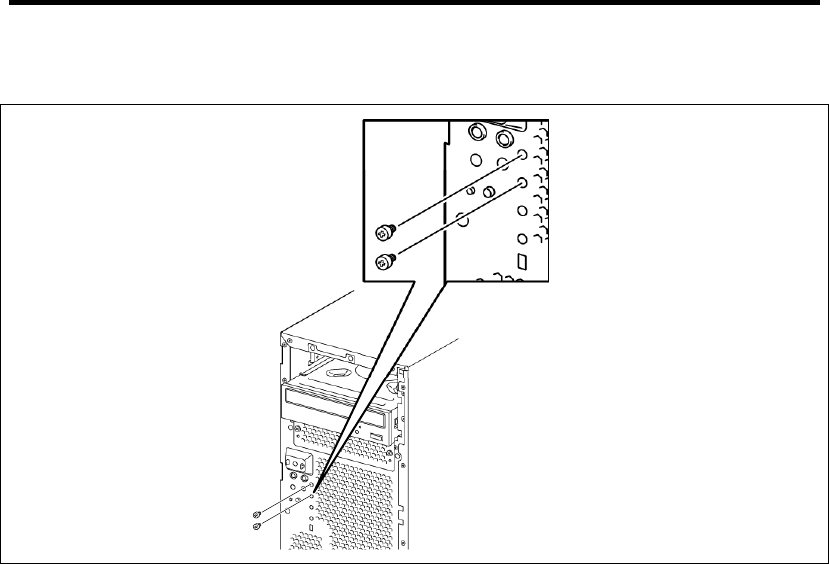
9-52 Upgrading Your Server
5. Remove the two dedicated screws attached to the front of the server.
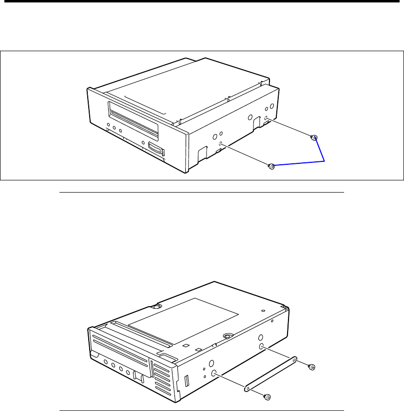
Upgrading Your Server 9-53
6. Fasten the two screws removed in step 5 to the right side of the device file.
NOTE:
When installing the N8151-59/76/90/101/102, insert the device
plates supplied with the server on the right side of the device and
attach the device to the server using the supplied screws.
Install the device plates so that the round hole is at the front and
slotted hole is at the back.
Dedicated screws
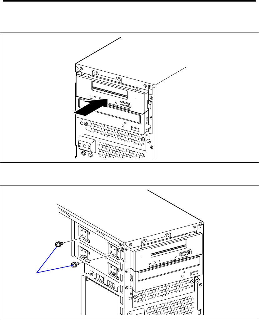
9-54 Upgrading Your Server
7. Insert a file device into the file bay.
8. Align the screw holes on the device with those on the file bay and secure the device by
using the two screws provided with the servver.
9. Connect the interface and power cables to the 5.25-inch device. See Chapter 10 for
details.
10. Assemble the server.
11. If a SCSI device is installed, set the parameters including the transmission rate using the
BIOS utility of the SCSI controller.
Refer to the manual provided with the SCSI controller for details.
Screw Set 504

Upgrading Your Server 9-55
12. Install the device driver for the installed device, if needed.
Refer to the manual provided with the device for details.
Removal
The file device can be removed in the reverse order of the installation. If the device is removed but
not installed again, install the EMI and dummy covers.
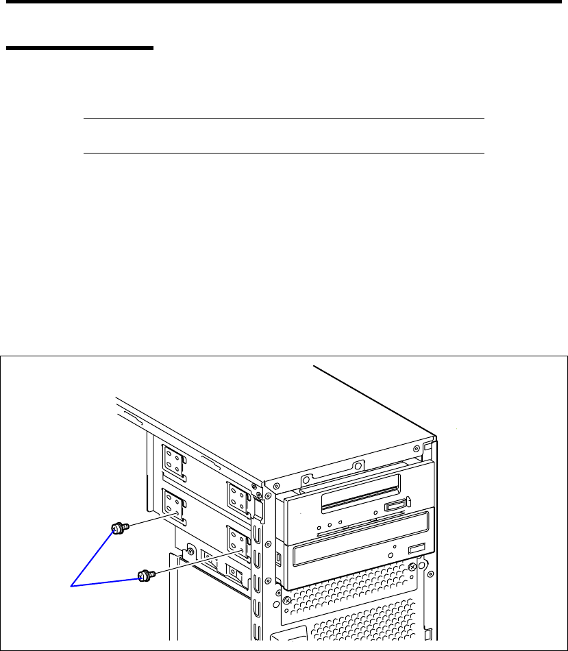
9-56 Upgrading Your Server
Optical Disk Drive
You may replace the factory-installed optical disk drive with an optional DVD SuperMULTI drive.
IMPORTANT: Be sure to use the DVD SuperMULTI drive authorized
by NEC.
Replacement Procedure
Take the following steps to install the optional DVD SuperMULTI drive.
1. See the section "Preparing for Installation and Removal" described earlier to prepare.
2. Remove the side cover and front bezel.
3. Disconnect all the interface and power cables from the factory-installed optical disk drive.
4. Remove the two screws securing the left side of the factory-installed optical disk drive.
Screw Set 504
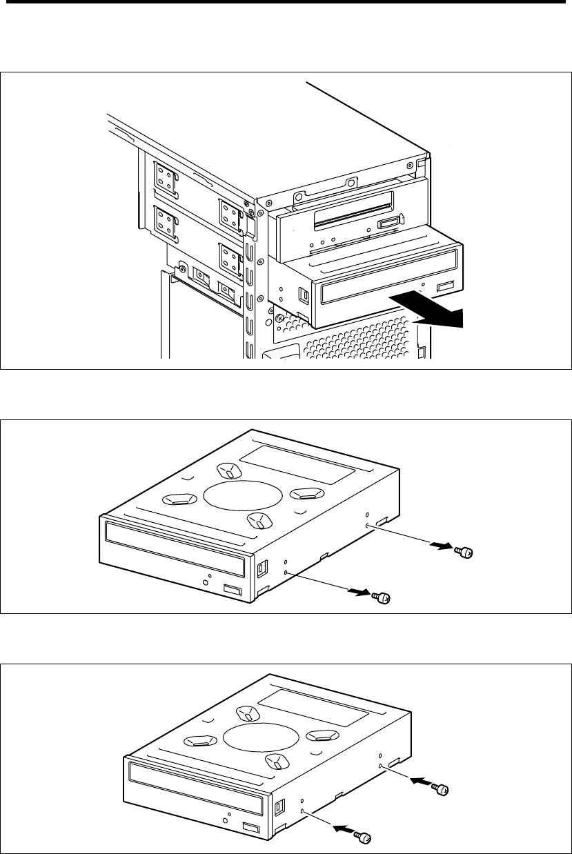
Upgrading Your Server 9-57
5. Remove the factory-installed optical disk drive.
6. Remove the two dedicated screws securing the right side of the factory-installed optical
disk drive.
7. Mount the two dedicated screws removed in Step 4 to the right side of the optional DVD
SuperMULTI drive.
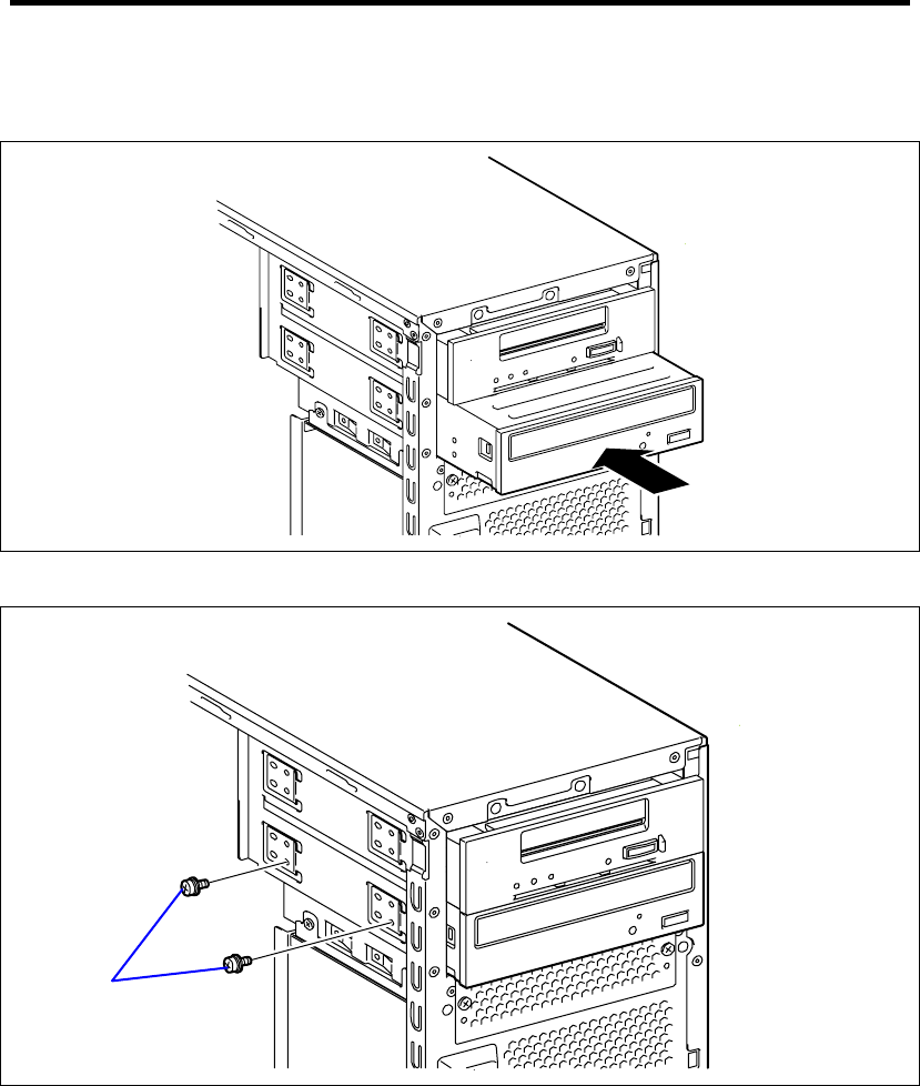
9-58 Upgrading Your Server
8. Insert the optional DVD SuperMULTI drive in the place from where the factory-installed
optical disk drive was removed.
9. Secure the optional DVD SuperMULTI drive with the screws removed in Step 4.
10. Connect the interface and power cables removed in Step 3 to the optional DVD
SuperMULTI drive.
11. Install the components you have removed in earlier steps.
Removal
The optional DVD SuperMULTI drive can be removed in the reverse order of the installation.
Screw Set 504

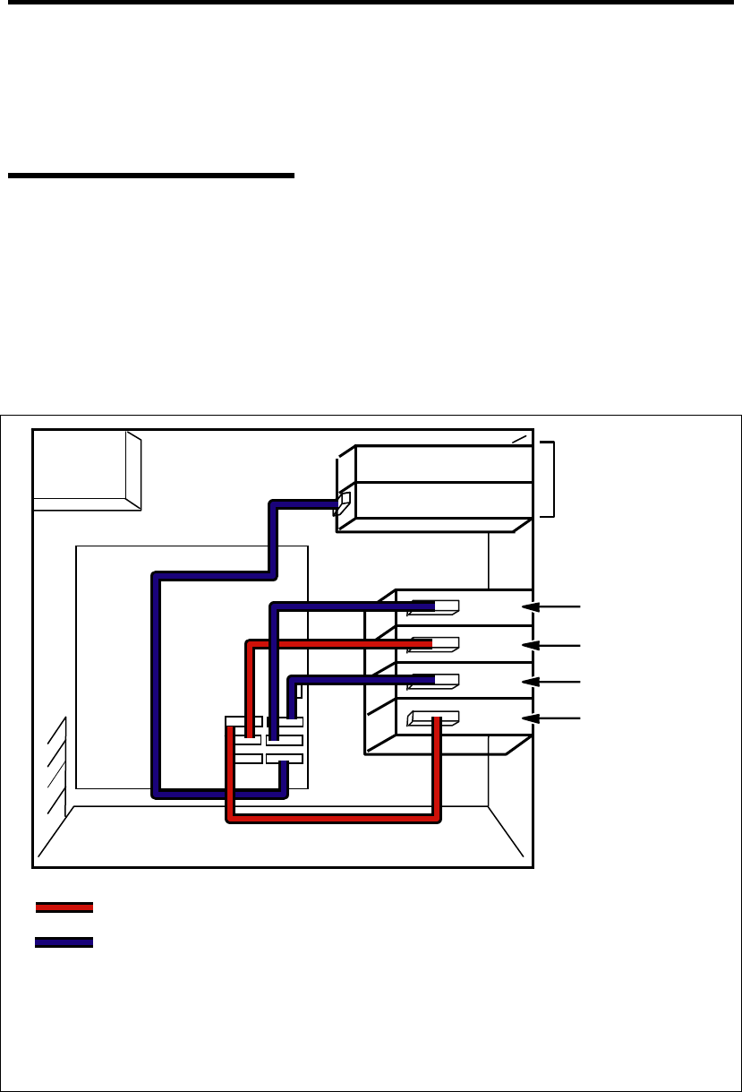
10-2 Internal Cabling Diagrams
INTERFACE CABLES
This section describes the connections of the interface cables.
Addition of Hard Disk Drive
The connection required when a hard disk drive is added is described below.
Installation of SATA Disks and SSDs Connected to On-board SATA Controller
If the serial ATA (SATA) hard disk drives and SSDs are added, connect the cables as shown in the
figure below.
Fill the hard disk drive cage with the hard disk drives from the bottom to top.
4th hard disk drive
3rd hard disk drive
2nd hard disk drive
1st hard disk drive
Power
Unit
Mother board
Optical disk drive
SATA cable for even-numbered port
5.25-inch device bay
SATA cable for odd-numbered port
SATA0
SATA2
SATA4
SATA1
SATA3
SATA5

Internal Cabling Diagrams 10-3
If two or more SATA hard disk drives are connected, you can configure a RAID System by using
the RAID Controller on the motherboard.
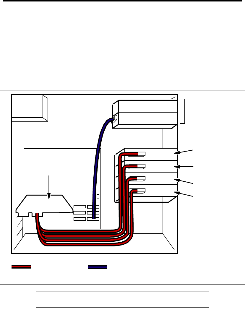
10-4 Internal Cabling Diagrams
When a SAS Hard Disk Drive, SATA Hard Disk Drive, or Solid State Drive is
Connected to the RAID Controller
If any drive is connected to the RAID Controller, you need the dedicated interface cable for
connection.
3.5-inch hard disk drive: K410-221(00) Internal SAS cable
2.5-inch hard disk drive: K410-220(00) Internal SAS cable
Fill the hard disk drive cage with the hard disk drives from the bottom to top.
NOTES: The RAID Controller must be connected when using a SAS
hard disk drive.
IMPORTANT:
SAS and SATA hard disk drives cannot be installed together.
RAID LED cable
To let the DISK Access lamp on the front panel indicate the access
states of the hard disk drives connected to the RAID Controller,
connect the LED cable provided with the server to the LED
4th hard disk drive
3rd hard disk drive
2nd hard disk drive
1st hard disk drive
Power
Unit
Mother board
Optical disk drive
SATA cable (for optical disk drive)
SAS cable
K410-220(00) or
K410-221(00)
RAID Controller
(N8103-109/116A/117A)
5.25-inch device bay
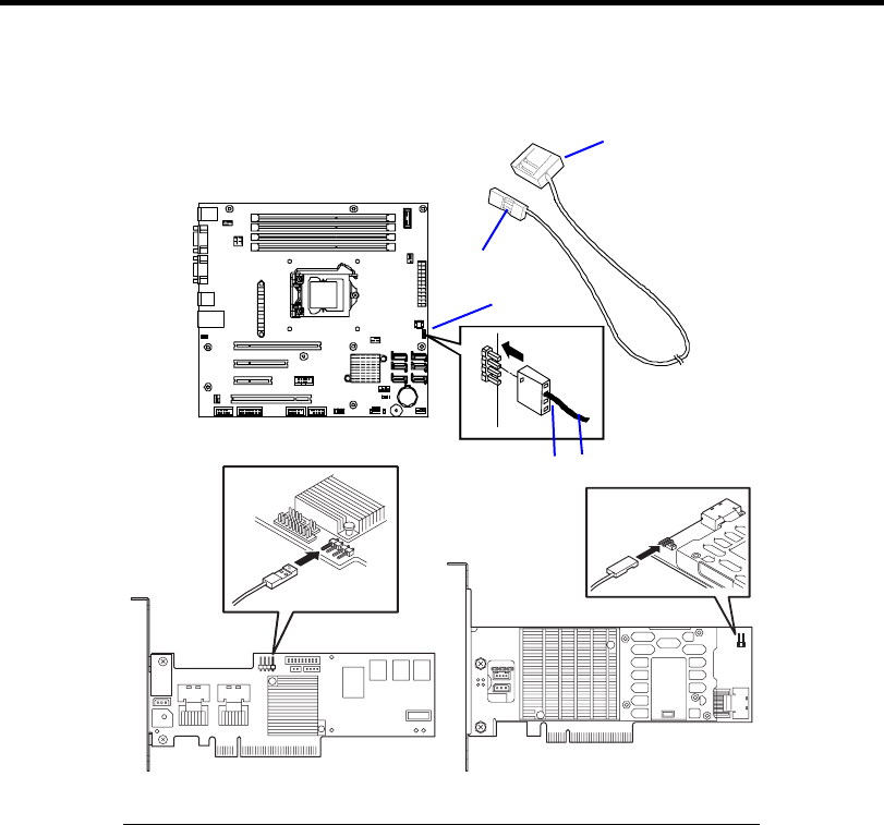
Internal Cabling Diagrams 10-5
connector on the mother board and the optional RAID Controller.
Mother board
LED connector
Red
Black
To mother board
To optional RAID
Controller
LED cable
RAID Controller N8103-116A/117A RAID Controller N8103-109
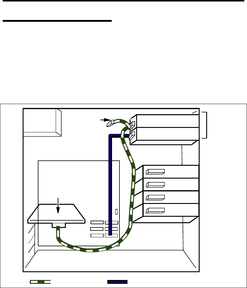
10-6 Internal Cabling Diagrams
Connection of 5.25-inch Device
The 5.25-inch device bay can be equipped with a SCSI device, an IDE device, or a USB device
(using internal connector).
Installation of SCSI Device
The SCSI controller and the SCSI cable (K410-160(00)) used for the connection is sold separately.
If the SCSI cable (K410-160(00)) sold separately has the connector for terminating the SCSI
connection, make the termination setting of the 5.25-inch device invalid.
Power
Unit
Mother board
Optical disk drive
SCSI Controlle
r
SCSI cable
(K410-160(00))
Terminato
r
5.25-inch
device bay
SATA cable for optical disk drive
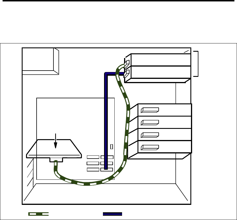
Internal Cabling Diagrams 10-7
Installation of SAS Device
The SAS controller and the SAS cable used for the connection are sold separately.
Power
Unit
Mother board
Optical disk drive
SATA cable for optical disk drive
SAS Controlle
r
SAS cable
5.25-inch
device bay
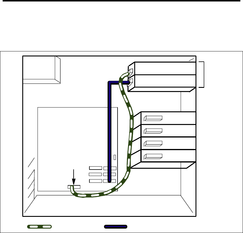
10-8 Internal Cabling Diagrams
Installation of USB Device (Internal Connector)
Use the K410-209(00) internal USB cable. (dedicated for this server). Do not use the USB cable
that comes with the device.
Power
Unit
Mother board
Optical disk drive
USB cable
USB Connector
(USB10_11)
5.25-inch
device bay
SATA cable for optical disk drive

Internal Cabling Diagrams 10-9
POWER CABLES
An example of the power cable connection is shown in the figure below. The server only uses the
power cables shown here.
Onboard SATA HDD
4th hard disk drive
3rd hard disk drive
2nd hard disk drive
1st hard disk drive
Power
Unit
Mother board
Optical disk drive
Power cable
P1
P2
P3
P10
P11
P14
P12
P15
5.25-inch device bay
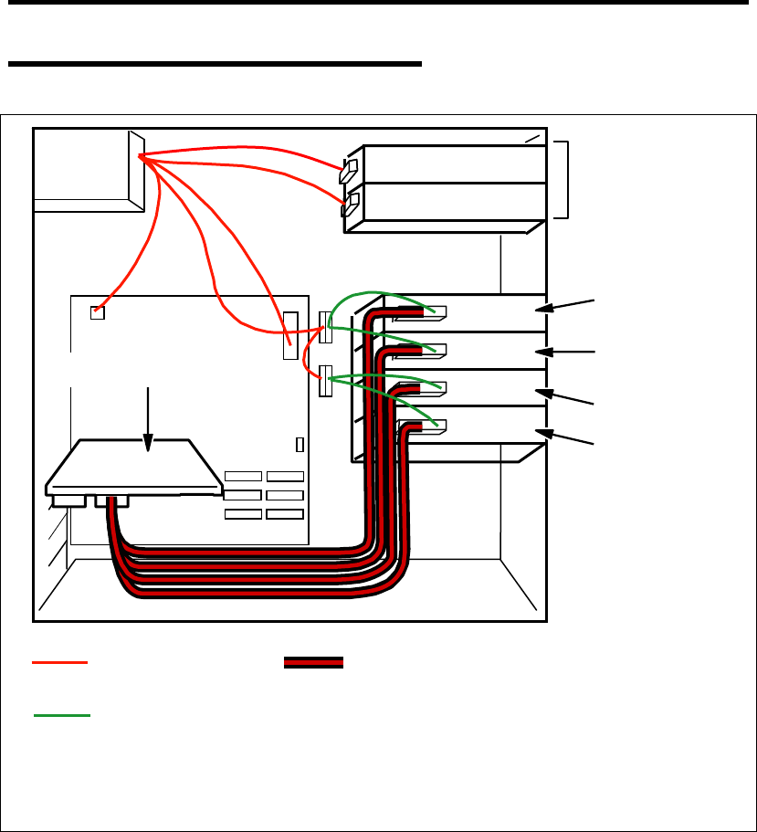
10-10 Internal Cabling Diagrams
With Optional RAID Controller Installed
4th hard disk drive
3rd hard disk drive
2nd hard disk drive
1st hard disk drive
Power
Unit
Mother board
Optical disk drive
Power cable
(power unit side)
P1
RAID Controller
(N8103-109/116A/117A)
P2
P3
P10
P8
P9
Internal SAS cable K410-220(00) or K410-221(00)
5.25-inch device bay
Power cable
(SAS cable side)

Appendix A
Specifications
NEC Express5800/GT110b
Item N8100-1592F N8100-1593F N8100-1594F
Type Intel® Celeron®
Processor G1101
Intel® Pentium®
Processor G6950
Intel® Xeon®
Processor X3430
Clock / Cache 2.26GHz/2MB 2.8GHz/3MB 2.4GHz/8MB
Number of processors 1
CPU
Maximum 1
Chipset Intel® 3420 (Intel® QuickPath Interconnect @25.6GB/s )
Standard 1GB (1GBx1)
Maximum 16GB (4MBx4, the standard DIMM must be replaced.)
Expansion unit 1 DIMM (DDR3-1333 SDRAM DIMM, unbuffered)
Memory
Memory module SDRAM DIMM (DDR3-1333, Dual channel memory configuration
supported)
Graphics XGI Technology Volari™ Z9s
Hard disk drive
(standard)
None
Hard disk drive
(maximum)
SATA2: 2TB × 4
Storage
Optical disk drive Standard: DVD-ROM drive (Read rate: DVD: x16 max., CD: x40 max.)
Option: DVD Super Multi drive (to be replaced with DVD-ROM drive)
5.25-inch device bay 2 slots (An optical disk drive is factory-installed.)
Additional PCI slot 4 slots (1 slot for PCI-EXPRESS (x16), 1 slot for PCI-EXPRESS (x4,
connector: x8), 1 slot for PCI-EXPRESS (x2, connector: x4), 1 slot for
PCI 32bit/33MHz)
Standard SATA (RAID0, 1, 10) Disk array
Option SATA/SAS (RAID0/1/5/6)
Keyboard MINI DIN 6-pin connector (1 port)
Mouse MINI DIN 6-pin connector (1 port)
USB 4-pin (Front: 2 ports, Rear: 4 ports, Internal: 4 ports), USB2.0 supported
Serial D-sub 9-pin (1 port)
Network RJ-45 (1 port, 1000BASE-T/100BASE-TX/10BASE-T)
External
interface
Display MINI D-sub 15-pin (1 port)
Cabinet design Desk-side, mini tower
External dimensions 175 (width) × 430 (height) × 367 (depth) mm
Weight 16 kg (Max.)
Power supply 100 to 120 VAC ±10%, 200 to 240 VAC ±10%, 50/60 Hz ±3 Hz
Power consumption 264 VA, 262 W
Temperature 10 to 35°C (operating), -10 to 55°C (non-operating, storage) Environmental
requirements Humidity 20 to 80% RH (no condensation)

A-2 Specifications
(This page is intentionally left blank.)
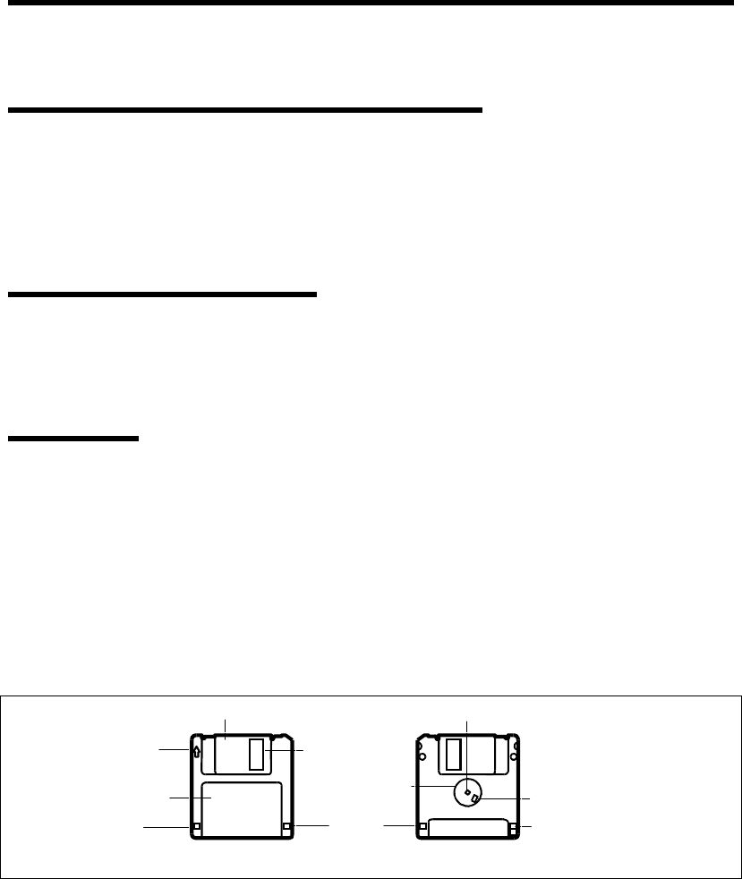
Appendix B
Other Precautions
Transfer Rate of the On-board LAN Controller
The onboard network interface controller supports 10Base-T and 100Base-TX networks and a
capable of full or half duplex.
The controller can automatically detect and switch for network speed and transfer mode connected
to the HUB. However, for proper network operation, specify the link speed and duplex mode to the
same value as the value specified for HUB.
Server Management Software
The NEC EXPRESSBUILDER DVD that comes with the server contains the NEC ESMPRO utility.
NEC recommends that you should install the NEC ESMPRO for effective use of the reliability
enhancement features of the server.
Floppy Disk
The following describes use of the floppy disk.
Floppy disk type
The server uses 3.5-inch floppy disks. You can use the following two types of 3.5-inch floppy disks:
2HD floppy disk (double-sided high-density track type)
Stores data of 1.44MB.
2DD floppy disk (double-sided double-density track type)
Stores data of 720KB.
Shutter
Insertion direction
indicator
Centering hub
Catching hole
Head window
Centering hole
Label
RearFront
High-density media hole
(2HD only) Write protection switch
Write protection
hole

B-2 Other Precautions
Notes on use
The floppy disk is an important data storage media with delicate structure and requires care. Keep
the following notes in mind to use it:
Insert the floppy disk into the floppy disk drive gently as far as it goes.
Attach the label to the correct position.
Do not write anything directly onto the disk surface with a pencil or ball-point pen.
Do not open the shutter.
Do not use the floppy disk in a dusty place.
Do not place anything on the floppy disk.
Do not leave the floppy disk in a high-temperature place (e.g., place exposed to direct
sunlight or close to a heater).
Do not leave the floppy disk with foods and drinks, or in a place exposed to cigarette smoke.
Do not leave the floppy disk near any form of liquid or a chemical or in a place where a
chemical may be accidentally sprayed over them.
Do not place any magnetic objects (e.g., magnet) near the floppy disk.
Do not clip the floppy disk or drop it.
Keep the floppy disk in a floppy disk case that protects it from magnetism and dust.
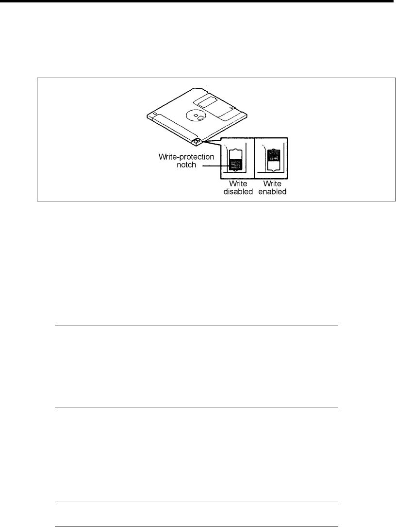
Other Precautions B-3
Write-protection
A floppy disk has a write-protect switch that prevents the stored data from accidental
erasure.
You can read data from a write-protected floppy disk, but you cannot save data into the
floppy disk or format it. NEC recommends that you should write-protect any floppy disk
containing valuable data unless you are about to save data.
To write-protect a 3.5-inch floppy disk, use the write-protect switch provided on its back.
Disk format
To write data into a floppy disk, the floppy disk must be "formatted." "Formatting" is to
initialize the floppy disk and make it available for the system environment (operating
system).
IMPORTANT:
Formatting a used floppy disk clears all the data contained in it, if
any.
Formatting a floppy disk from the DOS command line is not
available with the server. Use a formatted floppy disk to work with
it on the DOS command line.
The format method depends on your operating system. Refer to the manual that comes
with your operating system for details.
Data backup
"Data backup" is to copy data stored in a media into another media (e.g., floppy disk,
digital audio tape, or magnet-optical disk).
IMPORTANT: Make sure to make a back-up copy of every floppy
disk, if provided.
The floppy disk is a very delicate storage media. Dust or thermal changes, as well as
operator's misconduct or sever failures, may cause loss of data. To avoid loss of data, NEC
recommends that you should make a back-up copy of your valuable data on a regular
basis.

B-4 Other Precautions
DVD/CD-ROM
Keep the following notes in mind to use the DVD/CD-ROM for the server:
Press the center of the storage case to remove the DVD/CD-ROM from the case.
Do not drop the DVD/CD-ROM.
Do not place anything on the DVD/CD-ROM or bend the DVD/CD-ROM.
Do not attach any label onto the DVD/CD-ROM.
Do not touch the signal side (nothing is printed on this side) with your hand.
Place the DVD/CD-ROM with its printed side upward and gently put it on the tray.
Do not scratch the DVD/CD-ROM or write anything directly on it with a pencil or ball-point
pen.
Do not leave the DVD/CD-ROM with foods and drinks, or in a place exposed to cigarette
smoke.
Do not leave the DVD/CD-ROM in a high-temperature place (e.g., place exposed to direct
sunlight or close to a heater).
When dust or fingerprints are attached on the DVD/CD-ROM, wipe the DVD/CD-ROM
from its center to edge with a dry soft cloth slowly and gently.
Use the dedicated cleaner to clean the DVD/CD-ROM. Do not use record spray/cleaner,
benzene, or thinner.
Keep the DVD/CD-ROM in the dedicated case when not in use.
Tape Media
The following describes data handling with the DAT or AIT optionally available for the server.
Saving your valuable data
When you save your valuable data or programs into the cartridge tape, you should save
them into two cartridge tapes to make the primary and secondary tapes.
This enables you to restore your data from one tape when the other makes a read error, as
well as to protect your valuable data and programs from loss.
Three-generation data management
NEC recommends that you should employ three-generation data management for data
storage.
Three-generation data management uses three cartridge tapes: A, B, and C. You save data
to tape A on the first day, tape B on the second day, tape C on the third day, tape A on the
forth day, and so on. That is, you save data into cartridge tapes cyclically from tape A
through C.
This enables you, for example, to use tape B to restore the data when tape C makes a read
error. Also when both tapes B and C make a read error, you can restore your valuable data
by using the data stored in tape A.
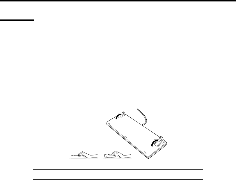
Other Precautions B-5
Keyboard
The keyboard is a device to instruct you computer by entering alphanumeric characters or symbols.
IMPORTANT:
Do not pour any liquid such as water or put anything into the
keyboard. Doing so may cause a failure of the keyboard.
The keyboard provided with the server is designed for adjustment of
an angle. Adjust the keyboard angle at which the keyboard is easy to
operate. The adjustment assists in reducing strain on your shoulders,
arms, and fingers.
NOTE: The keyboard functions depend on the software. Refer to the
manual that comes with the software for details.
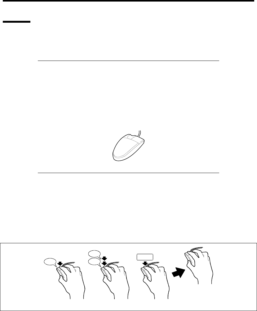
B-6 Other Precautions
Mouse
Like the keyboard, the mouse is a device to instruct your computer. Many OS's and application
software require the mouse for operation.
NOTE:
Functions assigned to the mouse buttons vary depending on the
software. For details, refer to the manual provided with the
software.
Use the mouse on a clean desk. Using the mouse on a dusty or dirty
desk disturbs smooth movement or normal operation of the mouse.
When your mouse movement seems dull, clean your mouse. (See
Chapter 7.)
Mouse operation includes "Click," "Double-click," and "Drag."
Click: Press the button only once and release it.
Double-click: Press the button twice consecutively and release it.
Drag: Press and hold the button and move the mouse.
Operation of the server involves combinations of these mouse operations and data entries with the
keyboard.
Pressin
g
Click
Click
Click
DragDouble-clickClick

Appendix C
IRQ
The factory-set interrupt requests are listed below. Find an appropriate one to install an optional
device.
IRQ Peripheral Device (Controller)
0 System timer
1 Keyboard
2 Cascade connection
3 COM2 serial port
4 COM1 serial port
5 PCI
6 Floppy disk
7 Parallel port
8 Real-time clock
9 Microsoft ACPI Compliant System
10 PCI
11 PCI
12 Mouse
13 Numeric processor
14 Primary IDE channel
15 Secondary IDE channel

C-2 IRQ
(This page is intentionally left blank.)

Appendix D
Installing Windows Server 2008 R2
This section explains how to install the Windows Server 2008 R2.
NOTICE
Read the following notes or information before installing the Windows Server 2008 R2.
Optional Board Supported by NEC EXPRESSBUILDER
The NEC EXPRESSBUILDER DVD attached to your server supports the following optional
boards;
NOTE: If you want to install the other boards by using a driver floppy
disk ("OEM-Disk for Mass storage device"), except ones listed below,
see "Installing with the OEM-Disk for Mass storage device" and
"Installing Optional Mass Storage Driver" of "Parameter File Creator"
in Chapter 6.
Controllers supporting installation of OS with Express Setup
– N8103-109 RAID Controller (128 MB, RAID0/1/5/6)*
– N8103-116A RAID Controller (128 MB, RAID0/1)*
– N8103-117A RAID Controller (128 MB, RAID0/1/5/6)*
– Onboard RAID Controller (LSI Embedded MegaRAID™)
Other controllers
– N8103-75 SCSI Controller*
– N8103-104A SAS Controller*
– N8103-107 SCSI Controller*
* Option.

D-2 Installing Windows Server 2008 R2
Service Pack Which EXPRESSBUILDER Supports
The NEC EXPRESSBUILDER DVD attached to the server supports following combination of the
OS installation media and Service Pack.
Windows Server 2008 R2
– OS installation media (No Service Pack)
Installing Service Pack
You can install the Service Pack on the server. When the Service Pack is not attached to your system,
prepare it by yourself.
Updating System
If you modified the Windows system, execute "Update the system" in the Autorun Menu.
Installing on the Mirrored Volume
When re-installing the OS to a hard disk drive which has been upgraded to Dynamic Disk, only the
simple dynamic volume is available for installation.
If you want to install the OS on a volume that is mirrored using [Disk Management], invalidate the
mirroring and reset to the basic disk before the installation, and validate the mirroring again after the
installation.
You can create, invalidate, or delete the mirror volume by using [Disk Management] in [Computer
Management].
Mounting MO Device
Do not mount an MO device on your server during the Windows installation.
About Removable Media
Do not set removable media, such as DAT and LTO, into the device mounted on this computer
during the Windows installation.
Floppy Disk Drive
The internal floppy disk drive is not included in your system at the standard configuration. Prepare
the optional Flash FDD or USB FDD if necessary.

Installing Windows Server 2008 R2 D-3
About the System Partition Size
The system partition size can be calculated from the following formula.
When the system is Windows Server 2008 R2:
Required partition size =
size required to install OS + paging file size + dump file size + application size
Size required to install OS = 8,000MB (Full Installation)
or
= 3,500MB (Server Core Installation)
Paging file size (recommended) = Installed memory size * 1.5
Dump file size = Installed memory size + 300MB
Application size = Required size
IMPORTANT:
The above-mentioned partition size is the minimum partition size
required for system installation. Ensure sufficient partition size for
system operation.
Following numbers are the recommended size.
– Full Installation: 32,768MB (32GB) or more
– Server Core Installation: 10,240MB (10GB) or more
*1GB = 1,024MB
The above-mentioned paging file size is recommended for
collecting debug information (memory dump). The paging file with
initial size large enough to store the dump file in the Windows
Partition is required.
Correct debug information might not be able to be collected due to
virtual memory shortage when the paging file is insufficient, so set
an enough size of the paging file with the entire system.
Regardless of the size of the mounted memory, or the Write
debugging information (type of memory dump), the maximum size
of the dump file is 'The size of the mounted memory + 300MB'.
If you install any application program or the like, add necessary
space to the partition to install these programs.
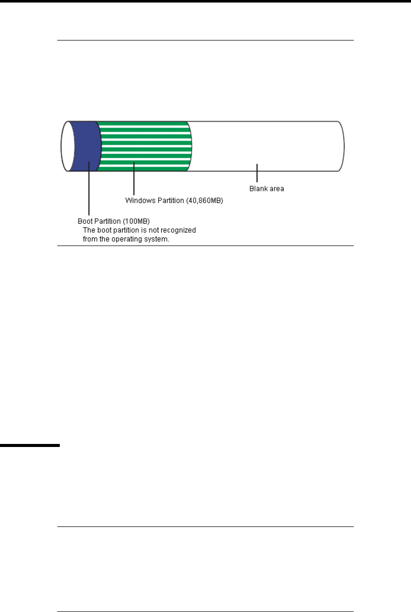
D-4 Installing Windows Server 2008 R2
NOTE: When new partition is created, initial 100MB is assigned as
boot partition by Windows OS.
Example:
If you make a partition of 40,960MB (40GB), usable space will be
40,960MB – 100MB = 40,860MB.
The partition size required for a system with an installed memory size of 1GB(1,024MB) and a full
installation of the operating system:
8,000MB + (1,024MB * 1.5) + (1,024MB + 300MB) + application size
= 10,860MB + application size.
If the provided partition size is smaller than that required to install the OS and paging file, expand
the partition size or utilize a larger disk. If your system does not have a sufficient dump file size,
divide the required file space into multiple disks by performing the steps below:
1. Set the system partition size to a size sufficient to install the OS and paging file.
2. See "Setting for Solving Problems" to write the debug information of the dump file onto
another disk.
If there is not enough disk space to write the debug information, add another disk for the dump file.
BitLocker
If you use BitLocker, note the following:
Be sure to keep the recovery password secure. Do not keep it around a server running
BitLocker.
IMPORTANT: Without the recovery password, you cannot start the
operating system and see the partition content encrypted by BitLocker.
The recovery password may be needed when you start the operating
system after performing the following tasks:
– Replacing the motherboard
– Initializing the TPM
– Changing the BIOS setting

Installing Windows Server 2008 R2 D-5
Windows Server 2008 is not installed in the partition encrypted by BitLocker.
For BitLocker, hotfix is provided by Microsoft. Before applying hotfix, check the
information written by Microsoft carefully. For more information, visit
http://support.microsoft.com/kb/975496/en-us.

D-6 Installing Windows Server 2008 R2
INSTALLING Windows Server 2008 R2
Preparations for Installation
NEC EXPRESSBUILDER DVD
Microsoft Windows Server 2008 R2 Standard (DVD-ROM)
User's Guide
Getting Started
Windows Server 2008 R2 OEM-Disk for EXPRESSBUILDER
Creating "Windows Server 2008 R2 OEM-Disk for EXPRESSBUILDER"
In case using Onboard RAID Controller (LSI Embedded MegaRAID™), create "Windows Server
2008 R2 OEM-Disk for EXPRESSBUILDER" before installation.
It does not need, except for using Onboard RAID Controller (LSI Embedded MegaRAID™).
NOTE: If you have already "Windows Server 2008 R2 OEM-Disk for
EXPRESSBUILDER" for NEC Express5800 server in which you are
going to install Windows Server 2008 R2, you do not need to create it
again.
NOTE: What is "OEM-Disk"?
In case of creating the disk for Windows Server 2008 R2:
It is called [Windows Server 2008 R2 OEM-Disk for
EXPRESSBUILDER].
You can create Windows Server 2008 R2 OEM-Disk for EXPRESSBUILDER with the following
two procedures.
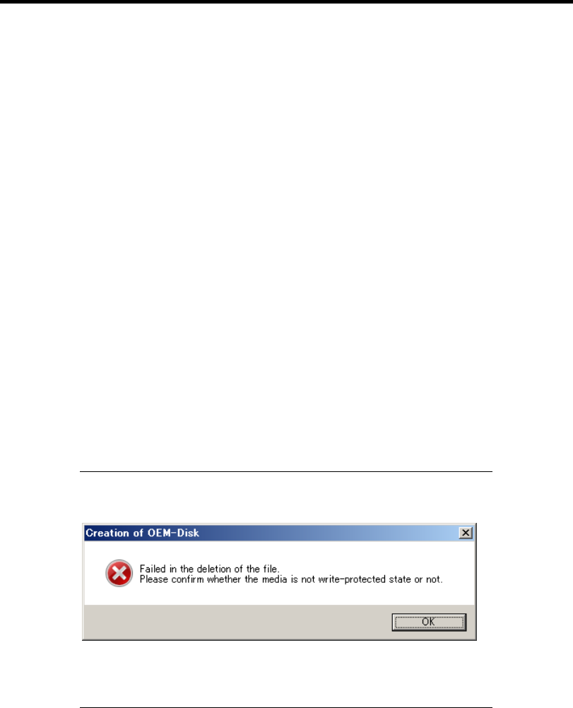
Installing Windows Server 2008 R2 D-7
Create from the menu which appears when running NEC Express5800 Server with
NEC EXPRESSBUILDER
If you have only NEC Express5800 server to create Windows Server 2008 R2 OEM-Disk for
EXPRESSBUILDER, use this procedure.
If Windows Server 2008 R2 can be operated on NEC Express5800 Server, you can use the other
procedure described later.
Follow the steps below.
1. Prepare one Flash FDD or 3.5-inch floppy disk.
2. Turn on your NEC Express5800 server.
3. Insert the NEC EXPRESSBUILDER DVD into the optical disk drive of the server.
4. Press the RESET switch or press Ctrl, Alt and Delete to reboot the server. (You may also
turn off and then on again to reboot the server.)
The system will boot from the DVD and NEC EXPRESSBUILDER starts.
5. Select [Create the OEM-Disk for Windows] from [Tools Menu] step.
6. Select [Create a Windows Server 2008 R2 OEM-Disk for EXPRESSBUILDER] at
[Create OEM-Disk] and click [Perform].
7. Windows Server 2008 R2 OEM-Disk for EXPRESSBUILDER will be created.
Write-protect and attach a label, then keep it safely.
NOTE: If the following message is displayed, the floppy disk is
write-protected.
Cancel write-protected state.
If you have already cancelled write-protected state, connect the floppy
disk drive again.

D-8 Installing Windows Server 2008 R2
Create from [Autorun Menu]
This menu requires Microsoft Windows XP, Vista or Windows Server 2003 (or later).
You can create Windows Server 2008 R2 OEM-Disk for EXPRESSBUILDER from [Autorun
Menu], if you have the computer on which the above operating systems operate.
Follow the steps below.
1. Prepare one Flash FDD or 3.5-inch floppy disk.
2. Start the Operating System.
3. Insert the NEC EXPRESSBUILDER DVD into the optical disk drive of the server.
The Menu will appear.
4. Click [Create drive disk] and select [OEM-Disk for Windows Server 2008 R2].
NOTE: You can do the same operation with the menu appeared by the
Right-click.
5. Windows Server 2008 R2 OEM-Disk for EXPRESSBUILDER will be created.
Write-protect and attach a label, then keep it safely.

Installing Windows Server 2008 R2 D-9
Windows Server 2008 R2 Clean Installation
This section explains how to perform a clean installation of Windows Server 2008 R2.
Follow steps below appropriate to your environment.
1. Turn on your system.
IMPORTANT: To install Windows Server 2008 R2, you may need to
update BIOS.
To check if your system needs a BIOS update, go to:
http://www.nec.com/express/
2. Insert the Windows Server 2008 R2 DVD-ROM into your DVD-ROM drive.
NOTE: When You use "Onboard RAID Controller (LSI Embedded
MegaRAID™)", "Windows Server 2008 R2 OEM-Disk for
EXPRESSBUILDER" is necessary.
3. Restart the system.
To restart the system, press Ctrl + Alt + Del or turn off the system once, and then turn it
on again.
IMPORTANT: When prompted to [press any key to boot from CD or
DVD], press Enter while the message is displayed.
If the Windows installation screen (shown in step 4) does not appear,
turn off the system, and then turn it on again.
The DVD-ROM starts. A message "Windows is loading files …" appears.
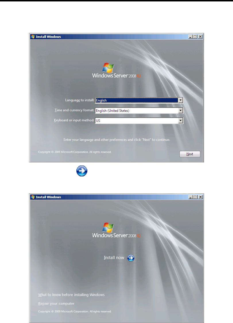
D-10 Installing Windows Server 2008 R2
4. Select a language and other options from the drop-down lists, and then click [Next].
5. Click the [Install now ] button.
The installation starts.
– If the following message is displayed:
Go to Step 6.
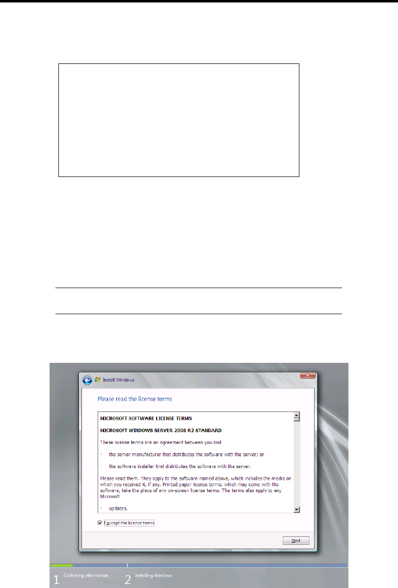
Installing Windows Server 2008 R2 D-11
– If the following message is not displayed:
Go to Step 9.
Load Driver
A required CD/DVD drive device driver is missing. If
you have a driver for floppy disk, CD, DVD, or USB flash
drive, please insert it now.
Note; If the Windows installation media is in the
CD/DVD drive, you can safely remove it for this step.
[Browse] [OK] [Cancel]
6. Insert the Windows Server 2008 R2 OEM-Disk for EXPRESSBUILDER, and press
[Browse].
7. When [Browse for Folder] window is displayed, select
<floppy disk drive>:\OEM-Disk\ws2008r2\megasr1, and press [OK].
8. Select [LSI Embedded MegaRAID] and press [Next].
9. Select the edition of the Windows operating system that you purchased.
NOTE: The Windows versions listed on the screen vary depending on
the Windows Server 2008 R2 DVD-ROM you are using.
10. Read the license terms carefully. If you agree, select [I accept the license terms], and then
click [Next].
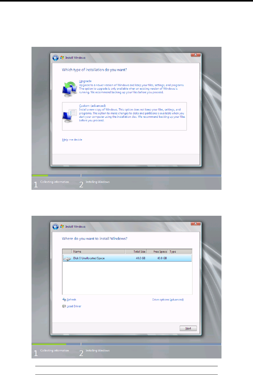
D-12 Installing Windows Server 2008 R2
11. Select the type of installation you want.
[Custom (advanced)] is selected below.
12. Select the disk where a partition will be created, and then click [Drive options
(advanced)].
IMPORTANT: If the partition has already been created, go to step 15.
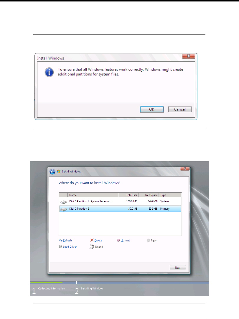
Installing Windows Server 2008 R2 D-13
13. Click [New], enter a partition size, and then click [Apply].
NOTE: When new partition is created, initial 100MB is assigned as
boot partition by Windows OS.
14. Select the partition created in step 13, and then click [Format].
15. Select the partition created, and then click [Next].
NOTE: The number of partitions displayed to a screen by environment
of the use is different.
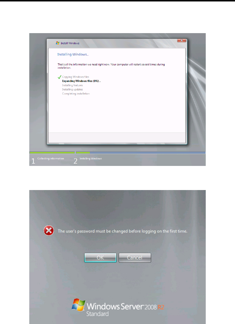
D-14 Installing Windows Server 2008 R2
When the following message appears, the installation starts automatically.
16. After a full installation of Windows Server 2008 R2 is completed, the following dialog
box will prompt you to set or change the password before you log on. Click [OK].
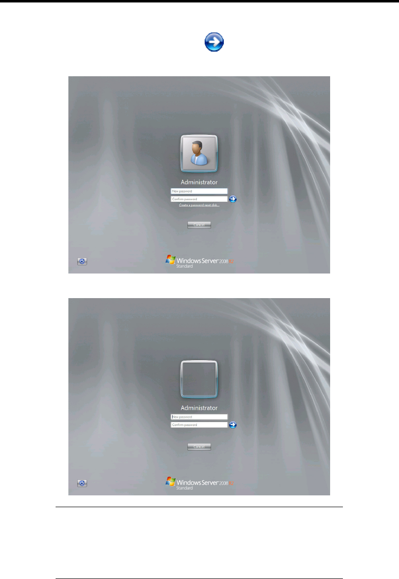
Installing Windows Server 2008 R2 D-15
17. Change the password, and then click the [ ] button.
– If you have selected a full installation
– If you have selected a Server Core installation
NOTE: Administrator password that satisfy the next condition, are
required.
More than 6 characters
Contains characters from three of the following categories (numbers,
uppercase letters, lowercase letters, and signs)
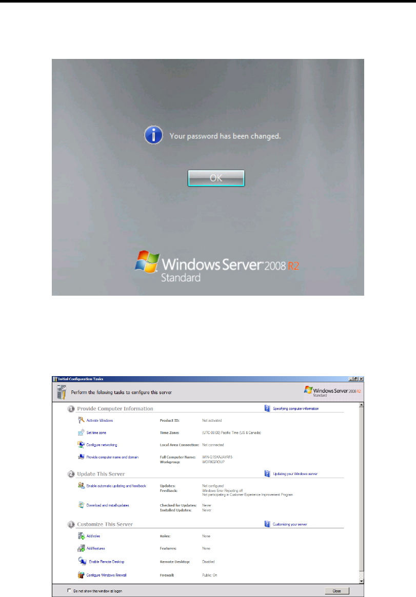
D-16 Installing Windows Server 2008 R2
18. When the following message appears, click [OK] to log on.
19. Log on to the system.
The steps vary depending on the edition you selected in step 9.
– If you have selected a full installation
On the [Initial Configuration Tasks] window, enter user information.
Installing Windows Server 2008 R2 D-17
– If you have selected a Server Core installation
At the command prompt, enter user information.
NOTE: For more detailed procedure, see the "Microsoft Windows
Server 2008 Step-By-Step Guide".
After installations is completed, be sure to execute the tasks described in "Setup of Device
Driver (Normally Install in Server)" and "Updating the System" of this chapter.

D-18 Installing Windows Server 2008 R2
Procedure for License Authentication
Product Key used in the procedure for license authentication should be matched with the COA label
in which the product key contained in Windows Server 2008 R2 is written.
NOTES:
Execute the activation within 30 days.
COA label may be attached to your server.
Updating the System
IMPORTANT: "Updating the System" disables the Scalable
Networking Pack (SNP) function.
The setting of SNP function may affect the system performance, so
refer to the attention of SNP detail in the following site before setting it.
http://www.nec.com/global/prod/express/
Update the system in the situation below:
CPU is expanded (expanded to single processor to multi-processor).
Modified system configuration.
Recovered the system using recovery process.
The system update brings the correction program provided by Microsoft to be applied to reinforce
the system security.
The system update is recommended.

Installing Windows Server 2008 R2 D-19
Application Process of "Updating the System"
"Updating the System" applies the drivers necessary for NEC Express5800 Series.
1. Log on to the system using an administrator account.
2. Insert the NEC EXPRESSBUILDER DVD into the optical disk drive.
3. Hereinafter, the setup process is depending on the content selected at [Installing Windows
Server 2008], follow each of the instructions.
– If you have selected a full installation
If the menu is displayed, click [Setup Windows] and click [Update the system].
NOTE: Right-clicking on the Menu produces the same outcome.
– If you have selected a Server Core installation
1) Execute the following command line from command prompt to specify the optical
disk drive (e.g. D drive).
cd /d d:\015\win\winnt\bin\oschk
C:\Users\administrator>cd /d D:\015\win\winnt\bin\oschk
2) Type following command line and press Enter.
oschk.bat
D:\015\win\winnt\bin\oschk>oschk.bat
4. The following box appears.
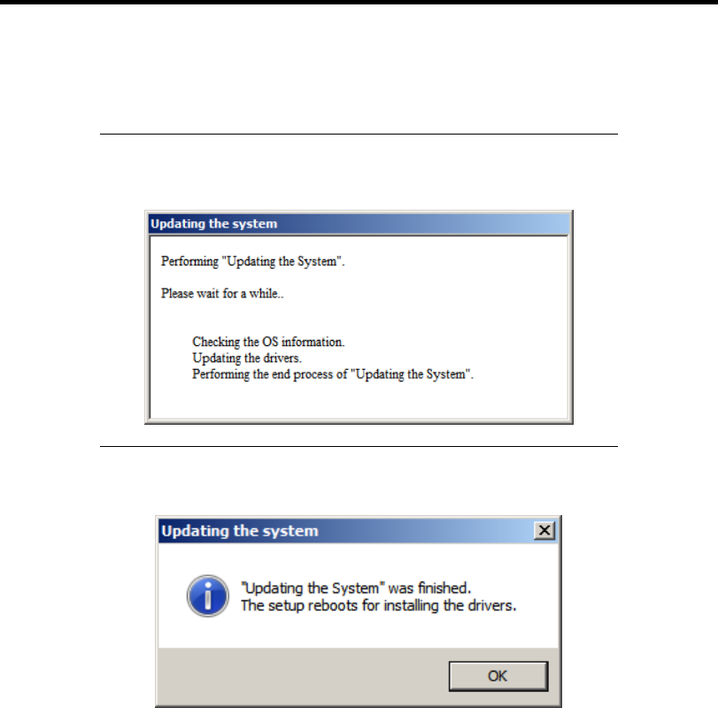
D-20 Installing Windows Server 2008 R2
5. Read the message, and then click [OK].
The update starts.
NOTE: The following box appears during the update if you have
deployed a full installation of Windows Server 2008. Wait until the
update completes.
6. When the following message appears, click [OK] to restart the system.
The system has been updated.

Installing Windows Server 2008 R2 D-21
DRIVER INSTALLATION AND ADVANCED SETTINGS
This section describes on how to install and setup various standard drivers mounted on the device.
For the information on installing and setting up the driver that is not described in this section, refer
to the document attached to the driver.
LAN Driver and PROSet
The LAN driver and PROSet have been installed automatically while your system was being
updated in the previous section.
NOTE: To change the LAN driver and PROSet settings, log on to the
system from a local console using an administrator account. Remotely
changing the settings by using the operating system’s remote desktop
feature is not supported.

D-22 Installing Windows Server 2008 R2
Network Driver
Specify the details of network driver.
Two standard network drivers that are mounted will be installed automatically, but the link speed
and Duplex mode need to be specified manually.
1. Open the [Device Manager]
2. Double-click [(Network Adapter Name)] in the list.
3. Click the [Link Speed] and specify the [Speed & Duplex] value the same as the value
specified for HUB.
4. Click [OK].
5. Restart the system
Also, add or delete any protocols and services if necessary.
You can operate the process on the property dialog box for local area network which can be
appeared from [Network and Dial-up Connection].
NOTE: We recommend you to add [Network Monitor] at [Adding
Services].
[Network Monitor] can monitor the frame (or the packet) that the
computer installing [Network Monitor] sends or receives. This tool is
valuable when analyzing network trouble. For information on how to
install the tool, see the "Setting for Solving Problems" described later in
this chapter.
Optional Network Board Driver (N8104-121/125A/126)
The drivers for Optional Network Board Driver (N8104-121/125A/126) are automatically installed
by Windows Plug-and-Play. You do not need to install them manually.

Installing Windows Server 2008 R2 D-23
Setup Team
Adapter Fault Tolerance (AFT) is a feature that creates a group containing more than one adapter
and automatically converts the process of the working adapter to the other adapter in the group
when any trouble occurred on that adapter.
Adaptive Load Balancing (ALB) is a feature that creates a group containing more than one adapter
and enhances the throughput by operating packet transmission from the server by all the adapters.
This feature includes AFT feature.
Switch Fault Tolerance (SFT) is a feature that provides a failover relationship between two ports
when each port is connected to a separate switch.
SFT supports two ports per team.
Static Link Aggregation (SLA) accounts for the GEC and 802.3ad static protocols.
SLA is a switch-assisted teaming mode and requires configuring ports at both ends of the link:
server interfaces and switch ports.
IMPORTANT:
AFT/ALB setup must be operated after system update and restarting
the system.
All the adapters specified as a group of Adapter Teaming must exist
on the same LAN. If they are connected to the separate switches,
they will not work normally.
The adapters specified as a group of Adaptive Load Balancing
(ALB) can be connected to only Switching Hub.
When exchange the mother board or option network card, make sure
to remove the adapter team before exchanges and recreate the
adapter team after exchange complete.
Confirm the port setting of switching hub (L2) matches the server
network adapter Teaming mode.
Teaming is not supported with Windows Server Core.
Create Team
1. Open the [Device Manager].
2. Open [Network adapters] → [Intel(R) xxx] properties.
3. Click [Teaming] tab and check the [Team this adapter with other adapters] check box.
Click [New Team].
4. Fill the name of the team in [Specify a name for the team] and click [Next].
5. Include the adapter to the team and click [Next].

D-24 Installing Windows Server 2008 R2
6. Select a team mode, and then click [Next].
IMPORTANT: Following team types are supported.
Adapter Fault Tolerance
Adaptive Load Balancing
Static Link Aggregation
Switch Fault Tolerance
7. Click [Finish].
IMPORTANT: Teaming an adapter with standard network adapter
and optional network adapter will cause the following message appear.
Click [OK] and continue the setting.
"One or more adapters in the team do not support true NDIS6.20
Receive-Side Scaling, Receive-Side Scaling will be disabled for the
team, Disabling Receive-Side Scaling will negatively impact the
performance of the team."
8. Click [TEAM: "Team name"] from [Device manager] → [Network adapters] to modify
the team. Click [Settings] tab and click [Modify Team] button.
9. Refer to the following procedure to set the team member adapter priority status.
– Set Primary
Point the adapter and click [Set Primary] button.
– Set Secondary
Point the adapter and click [Set Secondary] button.
NOTE: Adapter priority config can be confirmed by the following
procedure:
1. Click [TEAM: "Team name"] from [Device manager] → [Network
adapters].
2. Click [Settings] and confirm Adapters in team list.
10. Click [Test Switch] → [Run test] to confirm the adapter team is properly setup.
Confirm the result in [Test results].
11. Restart the system
Remove Team
1. Open the [Device Manager].
2. Click [Network adapters], and open [TEAM: "Team name"] properties.

Installing Windows Server 2008 R2 D-25
3. Click [Setting] tab.
4. Click [Remove Team] button.
5. Click [Yes] to the message.
6. Confirm [TEAM: "Team name"] adapter in not existing in [Network adapters] tree and
reboot the system.

D-26 Installing Windows Server 2008 R2
Setting WOL
Refer to the following procedure to enable WOL.
1. Start Device Manager.
2. Point to [Network adapters] and double click [Intel(R) 82547L Gigabit Network
Connection] to open the adapter [Properties].
3. Click [Power Management] tab and change setting in [Wake On LAN] according to the
following list.
Setting item Change setting
"Wake On Magic Packet" ON
"Wake on Magic Packet from power off state" ON
"Wake on Link" OFF
"Wake on Pattern Match" OFF
NOTES:
[Power Saver Options] setting is not necessary to change.
Above setting will be maintained until manually resetting are
executed.
IMPORTANT: The parameters of [Wake On LAN] will not exist, if
the network ports are not available for WOL.
4. Click [OK].
5. Restart the system

Installing Windows Server 2008 R2 D-27
Graphics Accelerator Driver
If you use standard graphics accelerator drivers, update your system with NEC
EXPRESSBUILDER DVD attached to your system.
Standard graphics accelerator drivers will be installed automatically.
NOTE: <Windows Server 2008>
The graphics accelerator driver is supported only on a server running a
full installation. Use VGA on a server running a Server Core
installation.
Observe the following procedure when you want to reinstall the driver individually.
1. Insert the NEC EXPRESSBUILDER DVD into the optical disk drive.
If the autorun menu is displayed, close menu screen.
2. Click Start menu, point to [Programs], [Accessories] and click [Windows Explorer].
3. Run "setup.exe" in the following directory.
\015\win\winnt\ws2008x64\r2\video
4. Follow the message to continue the installation.
If the dialog message "Digital Signature could not been found." appears, select [Yes] to
continue.
5. Remove the NEC EXPRESSBUILDER DVD from the optical disk drive, restart the
system.
Installing SCSI Controller Driver (N8103-75/107)
If you use the SCSI Controller N8103-75/107, you do not need to install the driver manually. It is
automatically installed by Windows Plug-and-Play.
Installing SAS Controller Driver (N8103-104A)
If you use the SAS Controller N8103-104A, you do not need to install the driver manually. It is
automatically installed by Windows Plug-and-Play.
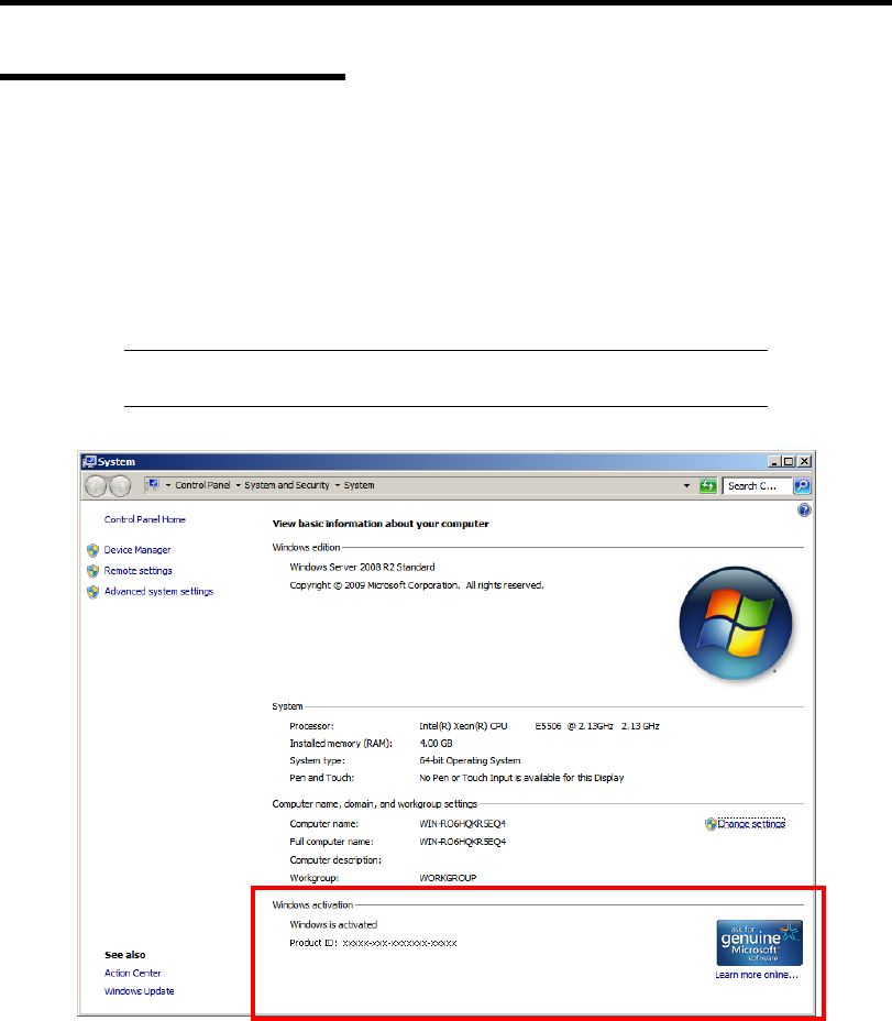
D-28 Installing Windows Server 2008 R2
About Windows Activation
Windows Server 2008 R2 must be activated before you can use Windows Server 2008 R2.
Windows activation process is as follows.
For a server running a full installation
1. Select [Control Panel] and click [System and Security], then select [System].
IMPORTANT: If the following message appears, Windows has already
been activated on your system.
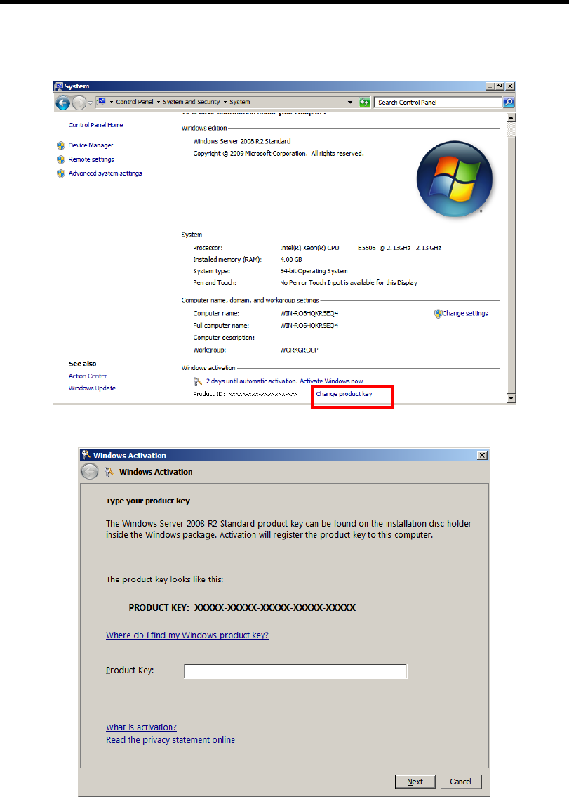
Installing Windows Server 2008 R2 D-29
2. In the following screen, click [Change product key].
3. Type the product key shown on your COA label, and click [Next].
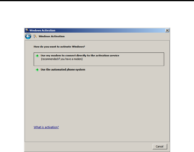
D-30 Installing Windows Server 2008 R2
4. Activate Windows.
The Windows activation is complete.
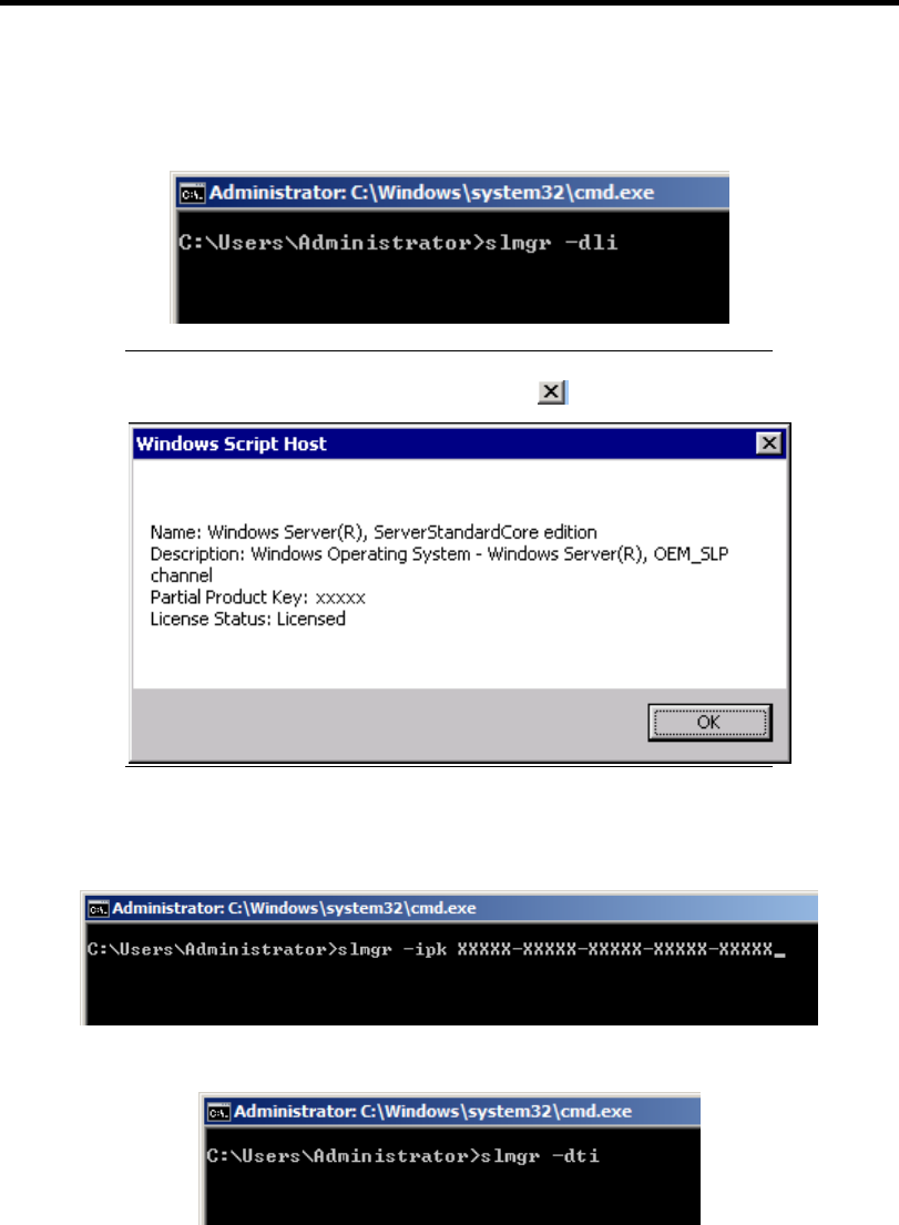
Installing Windows Server 2008 R2 D-31
For a server running a Server Core installation
1. At the command prompt, type slmgr –dli, and press Enter.
IMPORTANT: If the following message appears, Windows has
already been activated on your system. Click to exit.
2. Type slmgr –ipk <PID>, and press Enter.
* PID is your product key on the COA label.
3. Type slmgr –dti to obtain an installation ID for Windows activation, and press Enter.
4. See "%systemroot%\system32\sppui\phone.inf" for the phone number of the Microsoft
customer service.
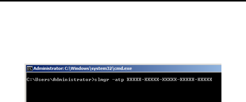
D-32 Installing Windows Server 2008 R2
5. Call the above number, inform the representative of the installation ID which you
obtained in step 3, and receive a confirmation ID.
6. At the command prompt, type slmgr –atp <CID>, and press Enter.
* CID is the confirmation ID that you received from the call center.
The Windows activation is complete.
SETTING FOR SOLVING PROBLEMS
Set for collecting memory dump using the procedure described in Chapter 5.

Appendix E
Installing Windows Server 2008
This section explains how to install the Windows Server 2008.
NOTICE
Read the following notes or information before installing the Windows Server 2008.
Optional Board Supported by NEC EXPRESSBUILDER
The NEC EXPRESSBUILDER DVD attached to your server supports the following optional
boards;
NOTE: If you want to install the other boards by using a driver floppy
disk ("OEM-Disk for Mass storage device"), except ones listed below,
see "Installing with the OEM-Disk for Mass storage device" and
"Installing Optional Mass Storage Driver" of "Parameter File Creator"
in Chapter 6.
Controllers supporting installation of OS with Express Setup
– N8103-109 RAID Controller (128 MB, RAID0/1/5/6)*
– N8103-116A RAID Controller (128 MB, RAID0/1)*
– N8103-117A RAID Controller (128 MB, RAID0/1/5/6)*
– Onboard RAID Controller (LSI Embedded MegaRAID™)
Other controllers
– N8103-75 SCSI Controller*
– N8103-95 SCSI Controller*
– N8103-104A SAS Controller*
– N8103-107 SCSI Controller*
* Option.

E-2 Installing Windows Server 2008
Service Pack Which EXPRESSBUILDER Supports
The NEC EXPRESSBUILDER DVD attached to the server supports following combination of the
OS installation media and Service Pack.
Windows Server 2008
– OS installation media (with Service Pack 2)
– OS installation media (No Service Pack) + Service Pack 2
– OS installation media (No Service Pack)
Installing Service Pack
You can install the Service Pack on the server. When the Service Pack is not attached to your system,
prepare it by yourself.
Updating System
If you modified the Windows system, execute "Update the system" in the Autorun Menu.
Installing on the Mirrored Volume
When re-installing the OS to a hard disk drive which has been upgraded to Dynamic Disk, only the
simple dynamic volume is available for installation.
If you want to install the OS on a volume that is mirrored using [Disk Management], invalidate the
mirroring and reset to the basic disk before the installation, and validate the mirroring again after the
installation.
You can create, invalidate, or delete the mirror volume by using [Disk Management] in [Computer
Management].
Mounting MO Device
Do not mount an MO device on your server during the Windows installation.
About Removable Media
Do not set removable media, such as DAT and LTO, into the device mounted on this computer
during the Windows installation.
Floppy Disk Drive
The internal floppy disk drive is not included in your system at the standard configuration. Prepare
the optional Flash FDD or USB FDD if necessary.

Installing Windows Server 2008 E-3
About the System Partition Size
The system partition size can be calculated from the following formula.
When the system is Windows Server 2008 64-bit (x64) Edition:
Required partition size =
size required to install OS + paging file size + dump file size + application size
Size required to install OS = 11,600MB (Full Installation)
12,300MB (Full Installation with Service Pack 2)
16,720MB (Full Installation + Service Pack 2)
or
= 4,100MB (Server Core Installation)
4,800MB (Server Core Installation with Service Pack 2)
9,220MB (Server Core Installation + Service Pack 2)
Paging file size (recommended) = Installed memory size * 1.5
Dump file size = Installed memory size + 300MB
Application size = Required size
IMPORTANT:
The above-mentioned paging file size is recommended for
collecting debug information (memory dump). The paging file with
initial size large enough to store the dump file in the boot drive is
required.
Correct debug information might not be able to be collected due to
virtual memory shortage when the paging file is insufficient, so set
an enough size of the paging file with the entire system.
Regardless of the size of the mounted memory, or the Write
debugging information (type of memory dump), the maximum size
of the dump file is 'The size of the mounted memory + 300MB'.
If you install any application program or the like, add necessary
space to the partition to install these programs.
Example:
The partition size required for a system with an installed memory size of 1GB(1,024MB) and a full
installation of the operating system:
11,600MB + (1,024MB * 1.5) + (1,024MB + 300MB) + application size = 14,460MB +
application size.
If the provided partition size is smaller than that required to install the OS and paging file, expand
the partition size or utilize a larger disk. If your system does not have a sufficient dump file size,
divide the required file space into multiple disks by performing the steps below:
1. Set the system partition size to a size sufficient to install the OS and paging file.
2. See "Setting for Solving Problems" to write the debug information of the dump file onto
another disk.
If there is not enough disk space to write the debug information, add another disk for the dump file.

E-4 Installing Windows Server 2008
When the system is Windows Server 2008 32-bit (x86) Edition
Required partition size =
size required to install OS + paging file size + dump file size + application size
Size required to install OS = 6,300MB (Full Installation)
9,300MB (Full Installation with Service Pack2)
9,400MB (Full Installation + Service Pack 2)
or
= 2,200MB (Server Core Installation)
5,200MB (Server Core Installation with Service
Pack2)
5,300MB (Server Core Installation + Service Pack 2)
Paging file size (recommended) = Installed memory size * 1.5
Dump file size = Installed memory size + 300MB
Application size = Required size
IMPORTANT:
The above-mentioned paging file size is recommended for
collecting debug information (memory dump). The paging file with
initial size large enough to store the dump file in the boot drive is
required.
Correct debug information might not be able to be collected due to
virtual memory shortage when the paging file is insufficient, so set
an enough size of the paging file with the entire system.
Depending on system configuration, 4096MB or more per partition
might not be able to be set to the paging file size.
Set it to 4095MB when the message to ask a value that is smaller
than 4096MB is displayed.
The maximum dump file size for the system with more than 2GB
memory mounted is '2048MB + 300MB'.
If you install any application program or the like, add necessary
space to the partition to install these programs.
Example:
The partition size required for a system with an installed memory size of 1GB (1,024MB) and a full
installation of the operating system:
6,300MB + (1,024MB * 1.5) + 1,024MB + 300MB + application size = 9,160MB +
application size.
If the partition where the operating system is installed is smaller than that required to install the OS
and paging file, expand the partition size or utilize a larger disk. If your system does not have a
sufficient dump file size, divide the required file space into multiple disks by performing the steps
below:
1. Set the partition size to a size sufficient to install the OS and paging file.
2. See "Setting for Solving Problems" to write the debug information of the dump file onto
another disk.
If there is not enough disk space to write the debug information, add another disk for the dump file.

Installing Windows Server 2008 E-5
BitLocker
If you use BitLocker, note the following:
Before you install Windows Server 2008, create two partitions:
– System partition for a loader
– Boot partition for the operating system
NOTE: For more information, see the following documentation in
Microsoft TechNet.
"Windows BitLocker Drive Encryption Step-by-Step Guide"
Be sure to keep the recovery password secure. Do not keep it around a server running
BitLocker.
IMPORTANT: Without the recovery password, you cannot start the
operating system and see the partition content encrypted by BitLocker.
The recovery password may be needed when you start the operating
system after performing the following tasks:
– Replacing the motherboard
– Initializing the TPM
– Changing the BIOS setting
Windows Server 2008 is not installed in the partition encrypted by BitLocker.

E-6 Installing Windows Server 2008
INSTALLING Windows Server 2008
Preparations for Installation
NEC EXPRESSBUILDER DVD
Microsoft Windows Server 2008 Standard (DVD-ROM)
User's Guide
Getting Started
Windows Server 2008 OEM-Disk for EXPRESSBUILDER
Creating "Windows Server 2008 OEM-Disk for EXPRESSBUILDER"
In case using Onboard RAID Controller (LSI Embedded MegaRAID™), create "Windows Server
2008 OEM-Disk for EXPRESSBUILDER" before installation.
It does not need, except for using Onboard RAID Controller (LSI Embedded MegaRAID™).
NOTE: If you have already "Windows Server 2008 OEM-Disk for
EXPRESSBUILDER" for NEC Express5800 server in which you are
going to install Windows Server 2008, you do not need to create it
again.
NOTE: What is "OEM-Disk"?
In case of creating the disk for Windows Server 2008 64-bit (x64)
Edition:
It is called [Windows Server 2008 x64 OEM-Disk for
EXPRESSBUILDER].
In case of creating the disk for Windows Server 2008 32-bit (x86)
Edition:
It is called [Windows Server 2008 OEM-Disk for
EXPRESSBUILDER].
You can create Windows Server 2008 OEM-Disk for EXPRESSBUILDER with the following two
procedures.

Installing Windows Server 2008 E-7
Create from the menu which appears when running NEC Express5800 Server with
NEC EXPRESSBUILDER
If you have only NEC Express5800 server to create Windows Server 2008 OEM-Disk for
EXPRESSBUILDER, use this procedure.
If Windows Server 2008 can be operated on NEC Express5800 Server, you can use the other
procedure described later.
Follow the steps below.
1. Prepare one Flash FDD or 3.5-inch floppy disk.
2. Turn on your NEC Express5800 server.
3. Insert the NEC EXPRESSBUILDER DVD into the optical disk drive of the server.
4. Press the RESET switch or press Ctrl, Alt and Delete to reboot the server. (You may also
turn off and then on again to reboot the server.)
The system will boot from the DVD and NEC EXPRESSBUILDER starts.
5. Select [Create the OEM-Disk for Windows] from [Tools Menu] step.
6. Connect the Flash FDD or insert a floppy disk into the floppy disk drive.
7. Select [Create a Windows Server 2008 OEM-Disk for EXPRESSBUILDER] at [Create
OEM-Disk] and click [Perform].
NOTE: In case of creating the disk for Windows Server 2008 64-bit
(x64) Edition, select [Create a Windows Server 2008 x64 OEM-Disk
for EXPRESSBUILDER].
8. Windows Server 2008 OEM-Disk for EXPRESSBUILDER will be created.
Write-protect and attach a label, then keep it safely.
NOTE: If the following message is displayed, the floppy disk is
write-protected.
Cancel write-protected state.
If you have already cancelled write-protected state, connect the floppy
disk drive again.

E-8 Installing Windows Server 2008
Create from [Autorun Menu]
This menu requires Microsoft Windows XP, Vista or Windows Server 2003 (or later).
You can create Windows Server 2008 OEM-Disk for EXPRESSBUILDER from [Autorun Menu], if
you have the computer on which the above operating systems operate.
Follow the steps below.
1. Prepare one Flash FDD or 3.5-inch floppy disk.
2. Start the Operating System.
3. Insert the NEC EXPRESSBUILDER DVD into the optical disk drive of the server.
The Menu will appear.
4. Connect the Flash FDD or insert the floppy disk into the floppy disk drive.
5. Click [Create drive disk] and select [OEM-Disk for Windows Server 2008].
NOTES:
In case of creating the disk for Windows Server 2008 64-bit (x64)
Edition, select [OEM-Disk for Windows Server 2008 x64].
You can do the same operation with the menu appeared by the
Right-click.
6. Windows Server 2008 OEM-Disk for EXPRESSBUILDER will be created.
Write-protect and attach a label, then keep it safely.
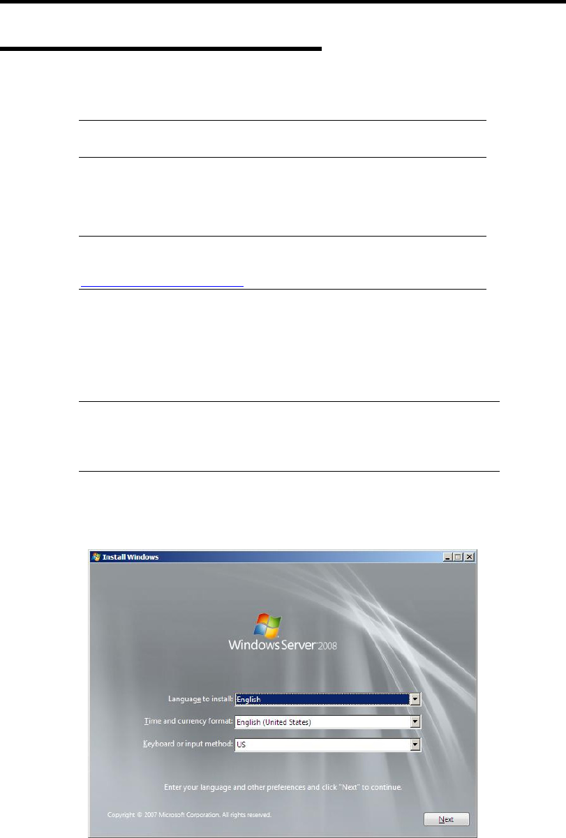
Installing Windows Server 2008 E-9
Windows Server 2008 Clean Installation
This section explains how to perform a clean installation of Windows Server 2008.
IMPORTANT: The installation procedure depends on your
environment.
Follow steps below appropriate to your environment.
1. Turn on your system.
IMPORTANT: To install Windows Server 2008, you may need to
update BIOS. To check if your system needs a BIOS update, go to:
http://www.nec.com/express/
2. Insert the Windows Server 2008 DVD-ROM into your DVD-ROM drive.
3. Restart the system.
To restart the system, press Ctrl + Alt + Del or turn off the system once, and then turn it
on again.
IMPORTANT: When prompted to [press any key to boot from CD or
DVD], press Enter while the message is displayed. If the Windows
installation screen (shown in step 4) does not appear, turn off the system,
and then turn it on again.
The DVD-ROM starts. A message "Windows is loading files …" appears.
4. Select a language and other options from the drop-down lists, and then click [Next].
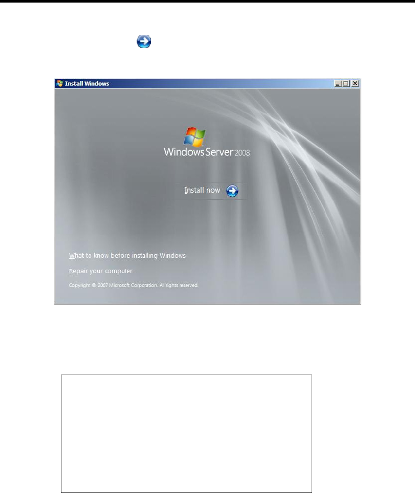
E-10 Installing Windows Server 2008
5. Click the [Install now ] button.
The installation starts.
– If the following message is displayed:
Go to Step 6.
– If the following message is not displayed:
Go to Step 9.
Load Driver
A required CD/DVD drive device driver is missing. If
you have a driver for floppy disk, CD, DVD, or USB flash
drive, please insert it now.
Note; If the Windows installation media is in the
CD/DVD drive, you can safely remove it for this step.
[Browse] [OK] [Cancel]
6. Insert the Windows Server 2008 OEM-Disk for EXPRESSBUILDER, and press
[Browse].
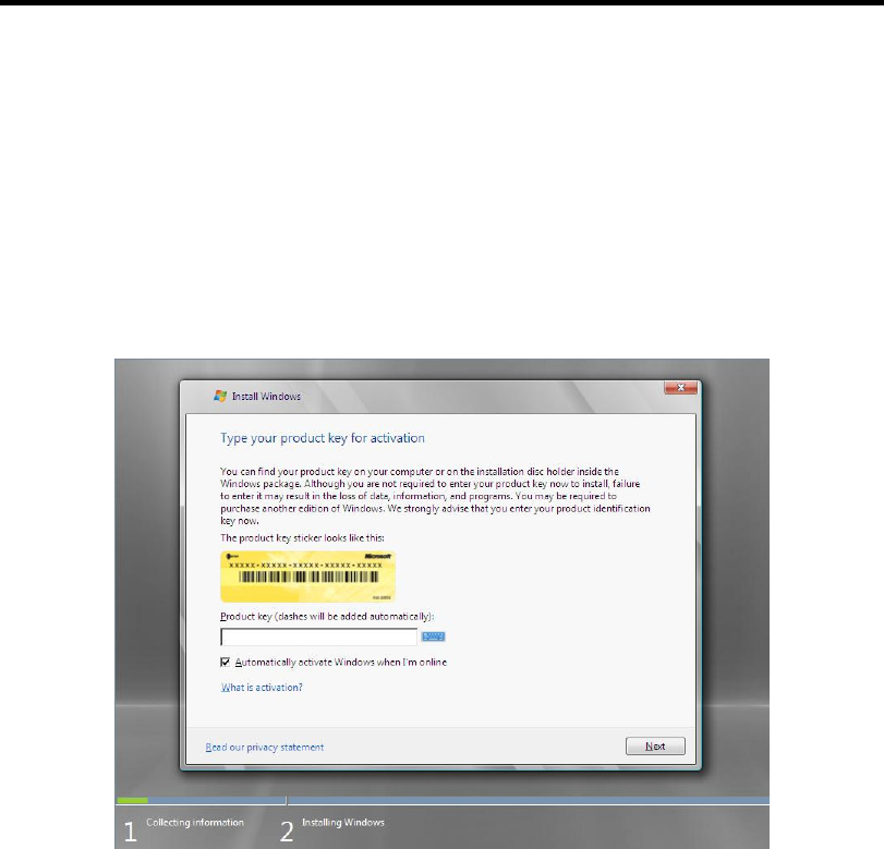
Installing Windows Server 2008 E-11
7. [Browse for Folder] window is displayed:
<Windows Server 2008 64-bit (x64) Edition>
Select <floppy disk drive>:\OEM-Disk\ws2008x64\megasr1, and press [OK].
<Windows Server 2008 32-bit (x86) Edition>
Select <floppy disk drive>:\OEM-Disk\ws2008\megasr1, and press [OK].
8. Select [LSI Embedded MegaRAID] and press [Next].
9. Enter your product key, and then click [Next].
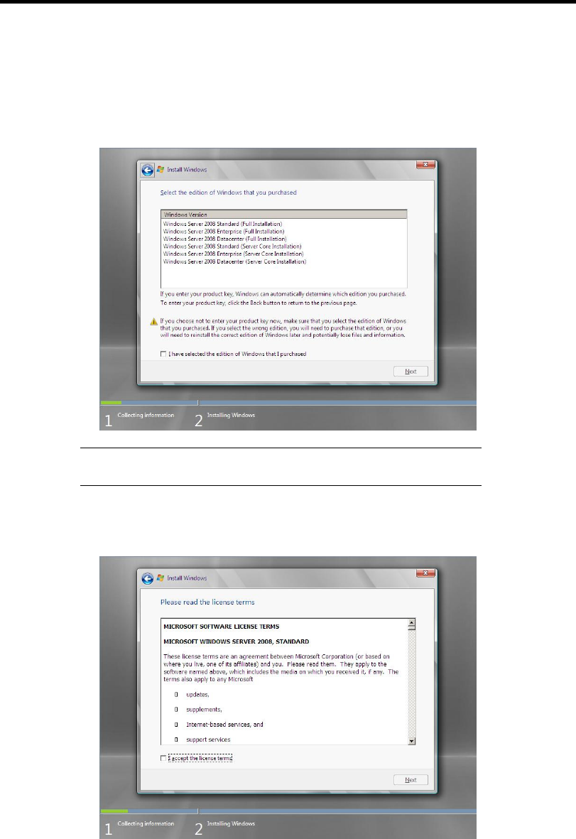
E-12 Installing Windows Server 2008
10. Select the edition of the Windows operating system that you purchased.
Select [I have selected the edition of Windows that I purchased], and then click [Next].
You will see only possible editions that have been determined by Windows based on the
key you entered in step 6.
NOTE: The Windows versions listed on the screen vary depending
on the Windows Server 2008 DVD-ROM you are using.
11. Read the license terms carefully. If you agree, select [I accept the license terms], and then
click [Next].
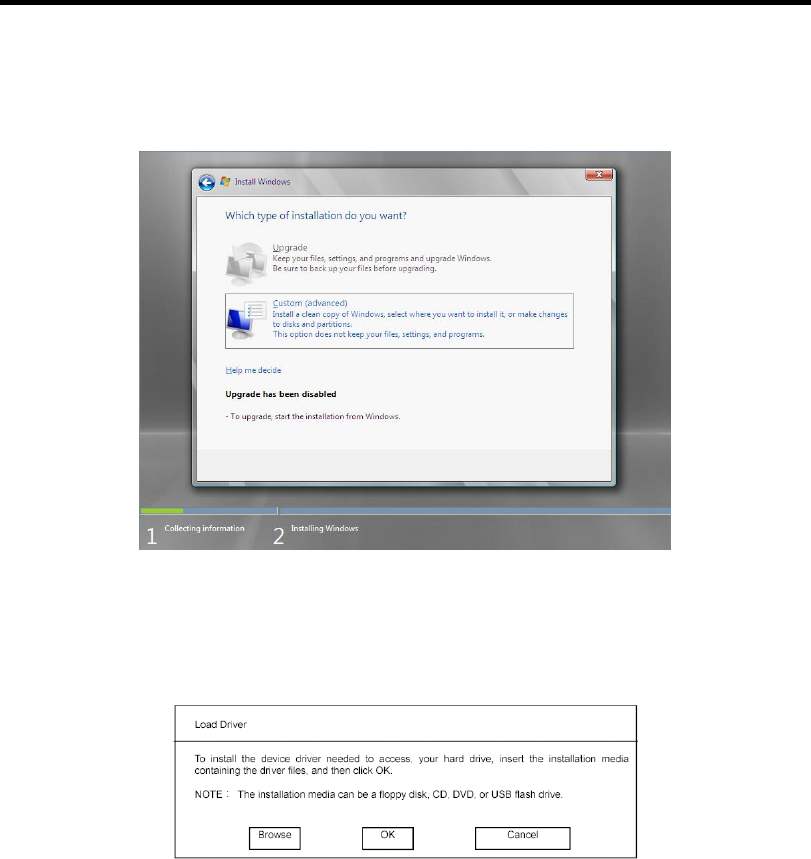
Installing Windows Server 2008 E-13
12. Select the type of installation you want.
[Custom (advanced)] is selected below.
13. The screen of "Where do you want to install Windows?" is displayed.
If the N8103-109/116A/117A RAID Controller is used:
Remove the Backup DVD-ROM or Windows Server 2008 DVD-ROM and set
EXPRESSBUILDER, and select [Load Driver].
Click [Browse], and go to Step 14.
If the N8103-109/116A/117A RAID Controller is not used:
Go to Step 16.

E-14 Installing Windows Server 2008
14. The folder reference dialog box appears.
Select a path in the NEC EXPRESSBUILDER DVD, and then click [OK].
If the N8103-109 RAID Controller is used:
– Windows Server 2008 32-bit (x86) Edition
<drive letter>:\015\win\winnt\oemfd\ws2008\fd1\stexstor
– Windows Server 2008 64-bit (x64) Edition
<drive letter>:\015\win\winnt\oemfd\ws2008x64\fd1\stexstor
If the N8103-116A/117A RAID Controller is used:
– Windows Server 2008 32-bit (x86) Edition
<drive letter>:\015\win\winnt\oemfd\ws2008\fd1\megasas
– Windows Server 2008 64-bit (x64) Edition
<drive letter>:\015\win\winnt\oemfd\ws2008x64\fd1\megasas
After you select the path, a list of drivers is displayed.
Select the following driver, and then click [OK]. Go to Step 15.
If the N8103-109 RAID Controller is used:
[Promise SuperTrak EX SAS RAID Controller]
If the N8103-116A/117A RAID Controller is used:
[LSI Logic MegaRAID SAS 8708EM2 RAID Controller]
15. Remove the EXPRESSBUILDER and set Backup DVD-ROM or Windows Server 2008
DVD-ROM.
16. Select the disk where a partition will be created, and then click [Drive Option].
IMPORTANT: If the partition has already been created, go to
step 19.
17. Click [New], enter a partition size, and then click [Apply].
18. Select the partition created in step 17, and then click [Format].
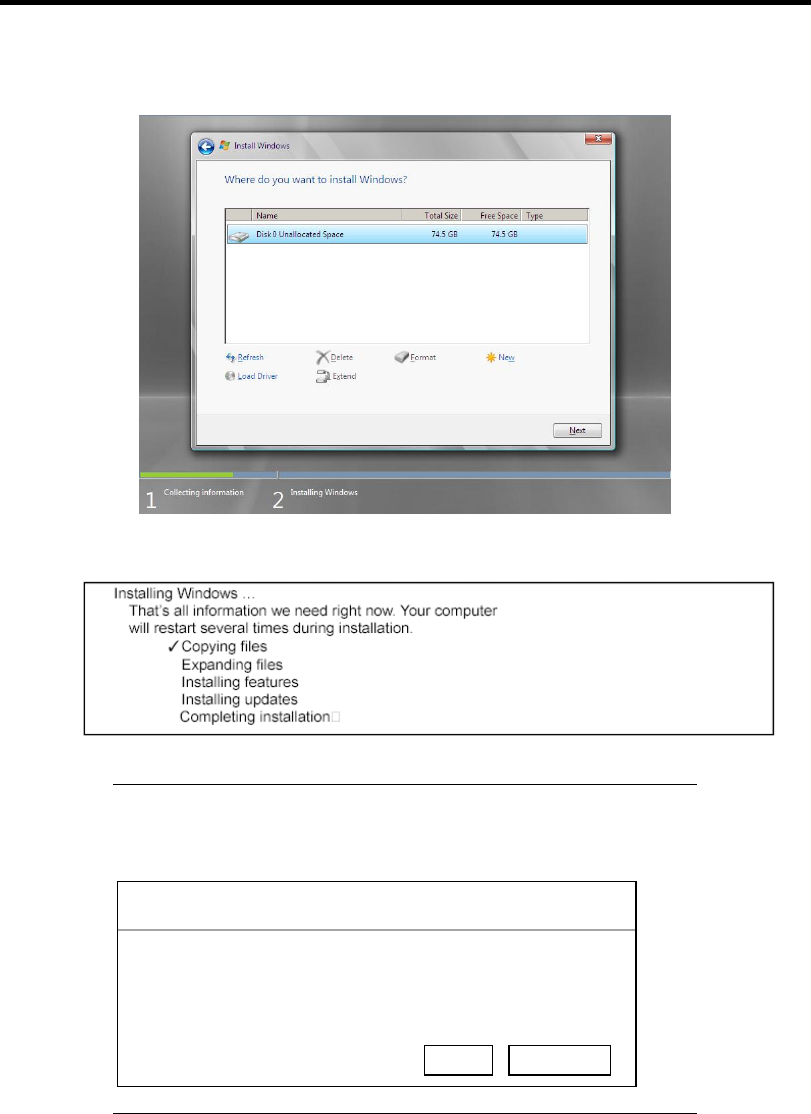
Installing Windows Server 2008 E-15
19. Select the partition created, and then click [Next].
When the following message appears, the installation starts automatically.
NOTE: If the disk drive contains NEC EXPRESSBUILDER DVD,
you will be prompted to replace a media with that for OS installation.
Insert the install media according to the on-screen message.
Install Windows – Insert Disc
Please insert Windows installation disc 1.
OK Cancel
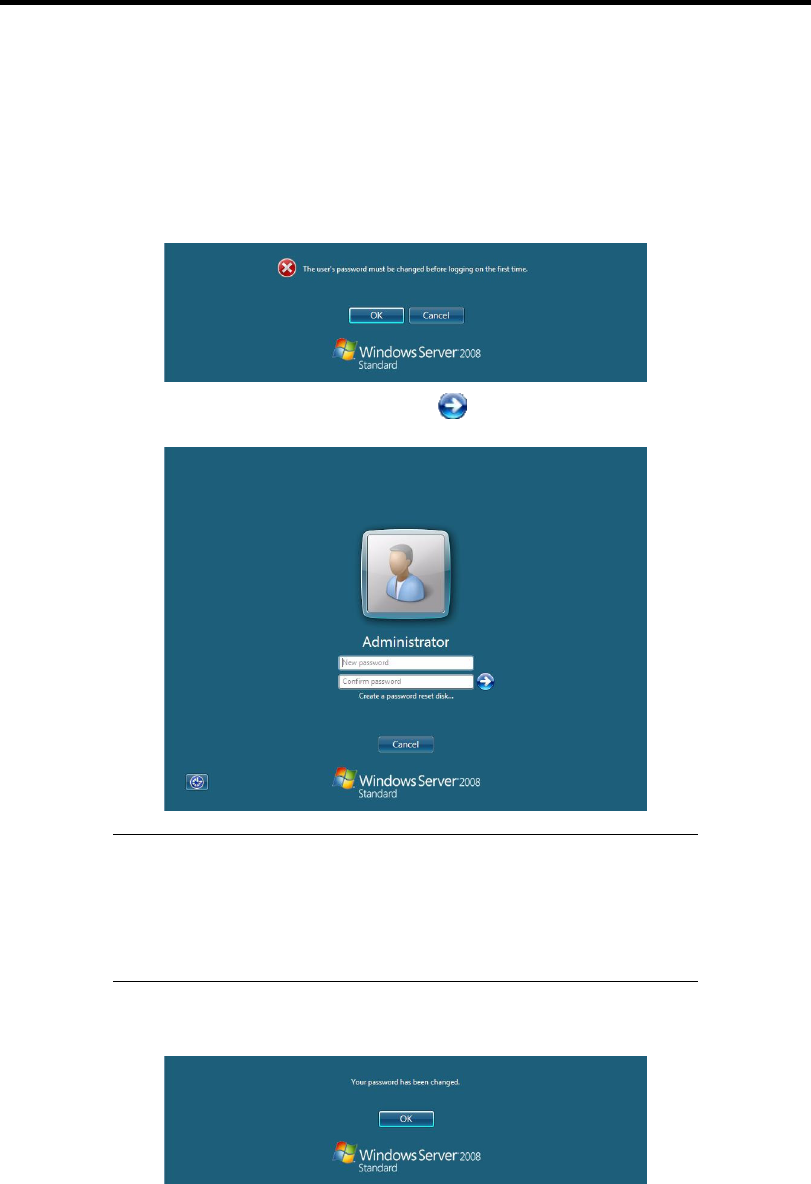
E-16 Installing Windows Server 2008
20. Log on to the system. The steps vary depending on the edition you selected in step 10.
If you have selected a full installation
1. After a full installation of Windows Server 2008 is completed, the following dialog box
will prompt you to set or change the password before you log on. Click [OK].
2. Change the password, and then click the button.
NOTE: Administrator password that satisfy the next condition, are
required.
More than 6 characters
Contains characters from three of the following categories (numbers,
uppercase letters, lowercase letters, and signs)
3. When the following message appears, click [OK] to log on.
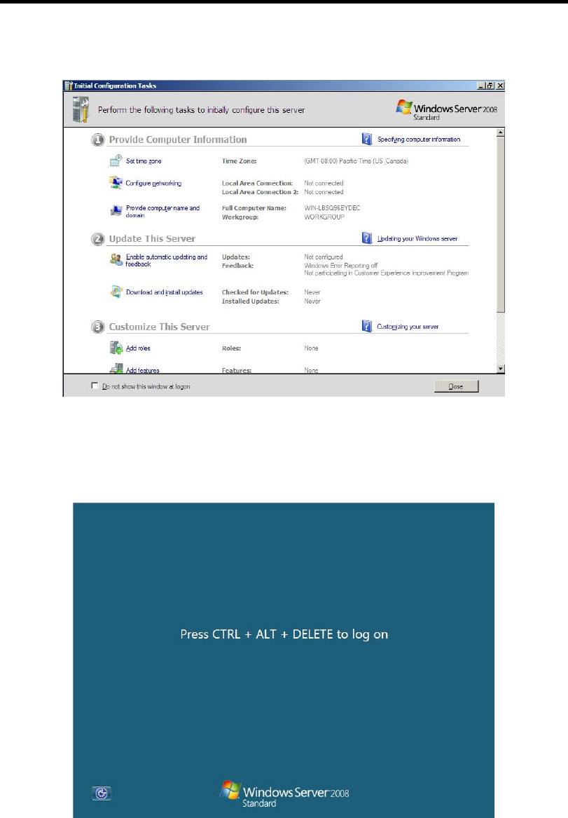
Installing Windows Server 2008 E-17
4. On the [Initial Configuration Tasks] window, enter user information.
If you have selected a Server Core installation
1. After a Server Core installation of Windows Server 2008 is completed, press Ctrl + Alt
+ Del.
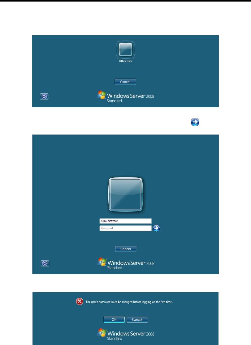
E-18 Installing Windows Server 2008
2. Select [Other User].
3. Log on to the system as an administrator.
You need not enter your password in this dialog box. Click the button.
4. Before you log on, you will be prompted to change the password. Click [OK].
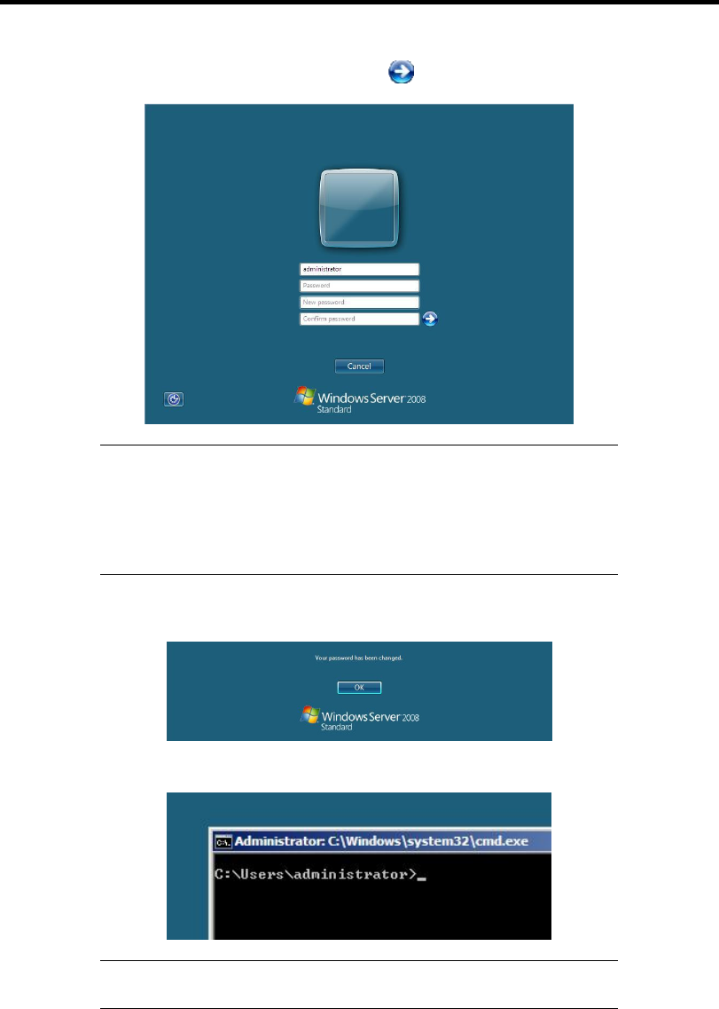
Installing Windows Server 2008 E-19
5. Change the password, and then click the button.
NOTE: Administrator password that satisfy the next condition, are
required.
More than 6 characters
Contains characters from three of the following categories (numbers,
uppercase letters, lowercase letters, and signs)
6. When the following message appears, click [OK].
7. At the command prompt, enter user information.
NOTE: For more detailed procedure, see the "Microsoft Windows
Server 2008 Step-By-Step Guide".
After installations is completed, be sure to execute the tasks described in "Setup of Device Driver
(Normally Install in Server)" and "Updating the System" of this chapter.

E-20 Installing Windows Server 2008
Procedure for License Authentication
Product Key used in the procedure for license authentication should be matched with the COA label
in which the product key contained in Windows Server 2008 is written.
NOTES:
Execute the activation within 60 days.
COA label may be attached to your server.
Updating the System
IMPORTANT: "Updating the System" disables the Scalable
Networking Pack (SNP) function.
The setting of SNP function may affect the system performance, so
refer to the attention of SNP detail in the following site before setting it.
http://www.nec.com/global/prod/express/
Update the system in the situation below:
CPU is expanded (expanded to single processor to multi-processor).
Modified system configuration.
Recovered the system using recovery process.
The system update brings the correction program provided by Microsoft to be applied to reinforce
the system security.
The system update is recommended.
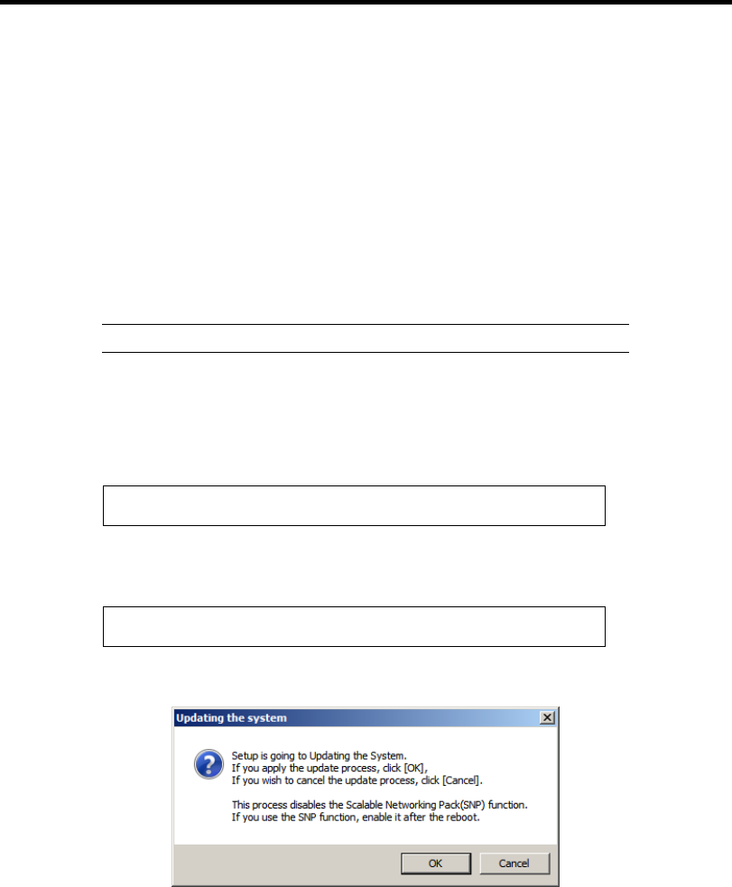
Installing Windows Server 2008 E-21
Application Process of "Updating the System"
"Updating the System" applies the drivers necessary for NEC Express5800 Series.
1. Log on to the system using an administrator account.
2. Insert the NEC EXPRESSBUILDER DVD into the optical disk drive.
3. Hereinafter, the setup process is depending on the content selected at [Installing Windows
Server 2008], follow each of the instructions.
– If you have selected a full installation
If the menu is displayed, click [Setup Windows] and click [Update the system].
NOTE: Right-clicking on the Menu produces the same outcome.
– If you have selected a Server Core installation
1) Execute the following command line from command prompt to specify the optical
disk drive (e.g. D drive).
cd /d d:\015\win\winnt\bin\oschk
C:\Users\administrator>cd /d D:\015\win\winnt\bin\oschk
2) Type following command line and press Enter.
oschk.bat
D:\015\win\winnt\bin\oschk>oschk.bat
4. The following box appears.
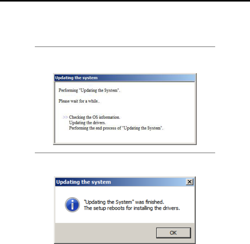
E-22 Installing Windows Server 2008
5. Read the message, and then click [OK].
The update starts.
NOTE: The following box appears during the update if you have
deployed a full installation of Windows Server 2008. Wait until the
update completes.
6. When the following message appears, click [OK] to restart the system.
The system has been updated.

Installing Windows Server 2008 E-23
DRIVER INSTALLATION AND ADVANCED SETTINGS
This section describes on how to install and setup various standard drivers mounted on the device.
For the information on installing and setting up the driver that is not described in this section, refer
to the document attached to the driver.
LAN Driver and PROSet
The LAN driver and PROSet have been installed automatically while your system was being
updated in the previous section.
NOTE: To change the LAN driver and PROSet settings, log on to the
system from a local console using an administrator account. Remotely
changing the settings by using the operating system’s remote desktop
feature is not supported.
Using N8104-125A Adapter after System Update
To use the N8104-125A Adapter after updating your system, you must first uninstall the LAN driver
and PROSet, and then update your system with the N8104-125A Adapter connected.
For a server running a full installation
1. Remove a team of network adapters.
NOTE: Before you remove, note down the current settings (e.g. IP
addresses) of the standard and optional adapters teamed for network
redundancy.
Configure the settings after reinstalling the LAN driver and PROSet. To
remove the team, see "Setup Team".
2. In [Control Panel], click [Uninstall Program].
3. Double-click [Intel(R) Network Connections 14.8.43.0].
Intel(R) Network Connections (Remove Options)] appears.
4. In [Remove Options], click [Remove].
[Intel(R) Network Connections - Remove Software] appears.
5. Select [Yes].
The uninstallation starts automatically.
6. When [InstallShield Wizard Completed] appears. Click [Finish].
Restart the system.

E-24 Installing Windows Server 2008
For a server running a Server Core installation
1. Note down the current settings (e.g. IP addresses) of the standard and optional adapters
teamed for network redundancy before uninstalling LAN driver.
Configure the settings after reinstalling the LAN driver.
2. At a command prompt, run "dxsetup.exe" in your removable medium containing the
Driver Set.
– Windows Server 2008 64-bit (x64) Editions:
<drive letter>: \015\win\winnt\ws2008x64\r148\apps\prosetdx\vistax64\dxsetup.exe
– Windows Server 2008 32-bit (x86) Editions:
<drive letter>: \015\win\winnt\ws2008\r148\apps\prosetdx\vista32\dxsetup.exe
3. In [IntelR Network Connections - InstallShield Wizard], click [Next].
4. Select [Remove], and click [Next].
5. Click [Remove].
Uninstallation starts automatically.
6. When [InstallShield Wizard Completed] appears, click [Finish].
Restart the system.

Installing Windows Server 2008 E-25
Network Driver
Specify the details of network driver.
Two standard network drivers that are mounted will be installed automatically, but the link speed
and Duplex mode need to be specified manually.
1. Open the [Device Manager]
2. Double-click [(Network Adapter Name)] in the list.
3. Click the [Link Speed] and specify the [Speed & Duplex] value the same as the value
specified for HUB.
4. Click [OK].
5. Restart the system
Also, add or delete any protocols and services if necessary.
You can operate the process on the property dialog box for local area network which can be
appeared from [Network and Dial-up Connection].
NOTE: We recommend you to add [Network Monitor] at [Adding
Services].
[Network Monitor] can monitor the frame (or the packet) that the
computer installing [Network Monitor] sends or receives. This tool is
valuable when analyzing network trouble. For information on how to
install the tool, see the "Setting for Solving Problems" described later in
this chapter.
Re-install the Network Driver
The network driver will be installed automatically.
Optional Network Board Driver (N8104-112/119/120/121/125A/126)
The following optional network boards are available for the N8104-112/119/120/121/125A/126.
To use the N8104-125A Adapter, see "Using N8104-125A Adapter after System Update" in Pages
E-23 to E-24.
The drivers for other network boards are automatically installed by Windows Plug-and-Play. You do
not need to install them manually.

E-26 Installing Windows Server 2008
Setup Team
Adapter Fault Tolerance (AFT) is a feature that creates a group containing more than one adapter
and automatically converts the process of the working adapter to the other adapter in the group
when any trouble occurred on that adapter.
Adaptive Load Balancing (ALB) is a feature that creates a group containing more than one adapter
and enhances the throughput by operating packet transmission from the server by all the adapters.
This feature includes AFT feature.
Switch Fault Tolerance (SFT) is a feature that provides a failover relationship between two ports
when each port is connected to a separate switch.
SFT supports two ports per team.
Static Link Aggregation (SLA) accounts for the GEC and 802.3ad static protocols.
SLA is a switch-assisted teaming mode and requires configuring ports at both ends of the link:
server interfaces and switch ports.
IMPORTANT:
AFT/ALB setup must be operated after system update and restarting
the system.
All the adapters specified as a group of Adapter Teaming must exist
on the same LAN. If they are connected to the separate switches,
they will not work normally.
The adapters specified as a group of Adaptive Load Balancing
(ALB) can be connected to only Switching Hub.
When exchange the mother board or option network card, make sure
to remove the adapter team before exchanges and recreate the
adapter team after exchange complete.
Confirm the port setting of switching hub (L2) matches the server
network adapter Teaming mode.
Teaming is not supported with Windows Server Core.
Create Team
1. Open the [Device Manager].
2. Open [Network adapters] → [Intel(R) xxx] properties.
3. Click [Teaming] tab and check the [Team this adapter with other adapters] check box.
Click [New Team].
4. Fill the name of the team in [Specify a name for the team] and click [Next].
5. Include the adapter to the team and click [Next].

Installing Windows Server 2008 E-27
6. Select a team mode, and then click [Next].
IMPORTANT: Following team types are supported.
Adapter Fault Tolerance
Adaptive Load Balancing
Static Link Aggregation
Switch Fault Tolerance
7. Click [Finish].
8. Click [TEAM: "Team name"] from [Device manager] → [Network adapters] to modify
the team. Click [Settings] tab and click [Modify Team] button.
9. Refer to the following procedure to set the team member adapter priority status.
– Set Primary
Point the adapter and click [Set Primary] button.
– Set Secondary
Point the adapter and click [Set Secondary] button.
NOTE: Adapter priority config can be confirmed by the following
procedure:
1. Click [TEAM: "Team name"] from [Device manager] → [Network
adapters].
2. Click [Settings] and confirm Adapters in team list.
10. Click [Test Switch] → [Run test] to confirm the adapter team is properly setup.
Confirm the result in [Test results].
11. Restart the system
Remove Team
1. Open the [Device Manager].
2. Click [Network adapters], and open [TEAM: "Team name"] properties.
3. Click [Setting] tab.
4. Click [Remove Team] button.
5. Click [Yes] to the message.
6. Confirm [TEAM: "Team name"] adapter in not existing in [Network adapters] tree and
reboot the system.

E-28 Installing Windows Server 2008
Setting WOL
Refer to the following procedure to enable WOL.
1. Start Device Manager.
2. Point to [Network adapters] and double click [Intel(R) 82547L Gigabit Network
Connection] to open the adapter [Properties].
3. Click [Power Management] tab and change setting in [Wake On LAN] according to the
following list.
Setting item Change setting
"Wake On Directed Packet" ON or OFF
"Wake On Magic Packet" ON
"Wake on Magic Packet from power off state" ON
"Wake on Link" OFF
IMPORTANT: DirectedPacket(*1) will not wake up the system on
Shutdown state even “Wake On Directed Packet” is setting to “ON”.
Only on Sleep or Hibernate state will wake up by a DirectedPacket.
(*1) Packet with the Ethernet address of the adapter in ethernet header
or Packet with an IP address assigned to the adapter in IP header.
NOTES:
[Power Saver Options] setting is not necessary to change.
Above setting will be maintained until manually resetting are
executed.
IMPORTANT: The parameters of [Wake On LAN] will not exist, if
the network ports are not available for WOL.
4. Click [OK].
5. Restart the system

Installing Windows Server 2008 E-29
Graphics Accelerator Driver
If you use standard graphics accelerator drivers, update your system with NEC
EXPRESSBUILDER DVD attached to your system.
Standard graphics accelerator drivers will be installed automatically.
NOTE: <Windows Server 2008>
The graphics accelerator driver is supported only on a server running a
full installation. Use VGA on a server running a Server Core
installation.
Observe the following procedure when you want to reinstall the driver individually.
1. Insert the NEC EXPRESSBUILDER DVD into the optical disk drive.
If the autorun menu is displayed, close menu screen.
2. Click Start menu, point to [Programs], [Accessories] and click [Windows Explorer].
3. Run "setup.exe" in the following directory.
– Windows Server 2008 64-bit (x64) Edition:
\015\win\winnt\ws2008x64\r1\video
– Windows Server 2008 32-bit (x86) Edition:
\015\win\winnt\ws2008\video
4. Follow the message to continue the installation.
If the dialog message "Digital Signature could not been found." appears, select [Yes] to
continue.
5. Remove the NEC EXPRESSBUILDER DVD from the optical disk drive, restart the
system.
Installing SCSI Controller Driver (N8103-75/95/107)
If you use the SCSI Controller N8103-75/95/107, you do not need to install the driver manually. It is
automatically installed by Windows Plug-and-Play.
Installing SAS Controller Driver (N8103-104A)
If you use the SAS Controller N8103-104A, you do not need to install the driver manually. It is
automatically installed by Windows Plug-and-Play.
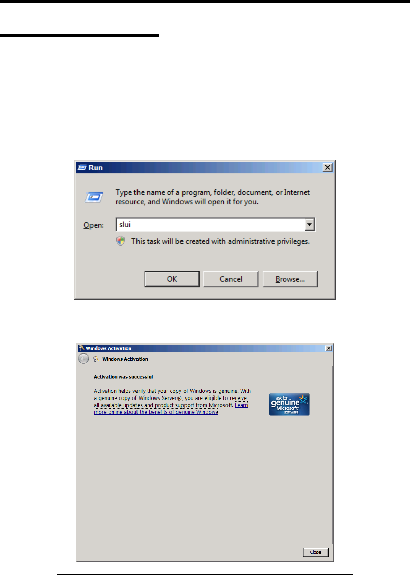
E-30 Installing Windows Server 2008
About Windows Activation
Windows Server 2008 must be activated before you can use Windows Server 2008.
Windows activation process is as follows.
For a server running a full installation
1. Go to the Start menu, and in the Run dialog box, type slui, and press Enter.
IMPORTANT: If the following message appears, Windows has
already been activated on your system. Click [Close] to exit.
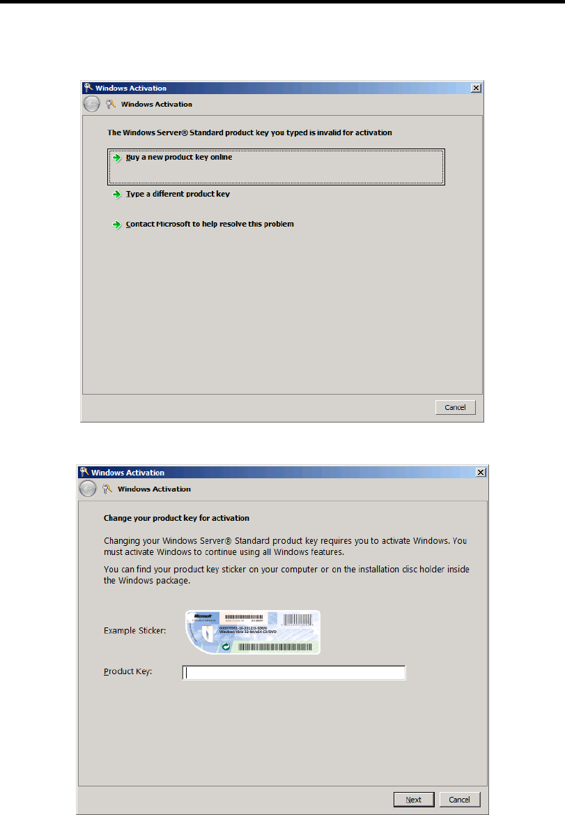
Installing Windows Server 2008 E-31
2. In the following screen, click [Type a different product key].
3. Type the product key shown on your COA label, and click [Next].
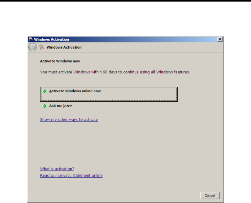
E-32 Installing Windows Server 2008
4. Activate Windows.
The Windows activation is complete.
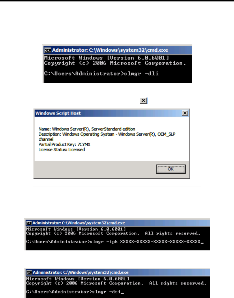
Installing Windows Server 2008 E-33
For a server running a Server Core installation
1. At the command prompt, type slmgr –dli, and press Enter.
IMPORTANT: If the following message appears, Windows has
already been activated on your system. Click to exit.
2. Type slmgr –ipk <PID>, and press Enter.
* PID is your product key on the COA label.
3. Type slmgr –dti to obtain an installation ID for Windows activation, and press Enter.
4. See "%systemroot%\system32\slui\phone.inf" for the phone number of the Microsoft
customer service.
5. Call the above number, inform the representative of the installation ID which you
obtained in step 3, and receive a confirmation ID.
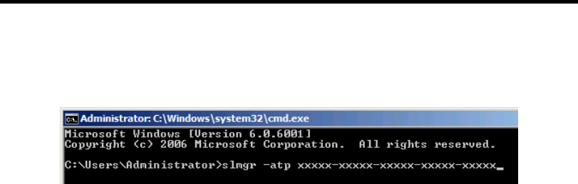
E-34 Installing Windows Server 2008
6. At the command prompt, type slmgr –atp <CID>, and press Enter.
* CID is the confirmation ID that you received from the call center.
The Windows activation is complete.
SETTING FOR SOLVING PROBLEMS
Set for collecting memory dump using the procedure described in Chapter 5.

Appendix F
Installing Windows Server 2003 x64 Editions
This section explains how to install the Windows Server 2003 x64 Editions.
NOTICE
Read the following notes or information before installing the Windows Server 2003 x64 Editions.
Optional Board Supported by NEC EXPRESSBUILDER
The NEC EXPRESSBUILDER DVD attached to your server supports the following optional
boards;
NOTE: If you want to install the other boards by using a driver floppy
disk ("OEM-Disk for Mass storage device"), except ones listed below,
see "Installing with the OEM-Disk for Mass storage device" and
"Installing Optional Mass Storage Driver" of "Parameter File Creator"
in Chapter 6.
Controllers supporting installation of OS with Express Setup
– N8103-109 RAID Controller (128 MB, RAID0/1/5/6)*
– N8103-116A RAID Controller (128 MB, RAID0/1)*
– N8103-117A RAID Controller (128 MB, RAID0/1/5/6)*
– Onboard RAID Controller (LSI Embedded MegaRAID™)
Other controllers
– N8103-75 SCSI Controller*
– N8103-95 SCSI Controller*
– N8103-104A SAS Controller*
– N8103-107 SCSI Controller*
* Option.

F-2 Installing Windows Server 2003 x64 Editions
Service Pack Which EXPRESSBUILDER Supports
The NEC EXPRESSBUILDER DVD attached to the server supports following combination of the
OS installation media and Service Pack.
Windows Server 2003 R2 x64 Edition
– OS installation media (with Service Pack 2)
– OS installation media (No Service Pack) + Service Pack 2
– OS installation media (No Service Pack)
Installing Service Pack
You can install the Service Pack on the server. When the Service Pack is not attached to your system,
prepare it by yourself.
Updating System
If you modified the Windows system, execute "Update the system" in the Autorun Menu.
Re-installing to the Hard Disk Drive which has been upgraded to
Dynamic Disk
If you want to leave the existing partition when installing the system on the hard disk drive
upgraded to Dynamic Disk, note the following issue:
Do not select the partition that OS had been installed as the partition to install the OS newly.
Select "Use the current File System" for the format of OS partition.
Mounting MO Device
Do not mount an MO device on your server during the Windows installation.
About Removable Media
Do not set removable media, such as DAT and LTO, into the device mounted on this computer
during the Windows installation.
Floppy Disk Drive
The internal floppy disk drive is not included in your system at the standard configuration. Prepare
the optional Flash FDD or USB FDD if necessary.

Installing Windows Server 2003 x64 Editions F-3
About the System Partition Size
The system partition size can be calculated from the following formula.
Size necessary to install the system + Paging File Size + Dump File Size
+ Application Size
Size necessary to install the system = 4100MB (Windows Server 2003 x64 Editions)
= 4100MB (Windows Server 2003 x64 Editions with
ServicePack 2)
= 5900MB (Windows Server 2003 x64 Editions +
Service Pack 2 CD-ROM)
Paging File Size (Recommended) = Mounted Memory Size * 1.5
Dump file Size = Mounted Memory Size + 1MB
Application Size = Required Size
IMPORTANT:
The above-mentioned paging file size is recommended for
collecting debug information (memory dump). The paging file with
initial size large enough to store the dump file in the boot drive is
required.
Correct debug information might not be able to be collected due to
virtual memory shortage when the paging file is insufficient, so set
an enough size of the paging file with the entire system.
Regardless of the size of the mounted memory, or the Write
debugging information (type of memory dump), the maximum size
of the dump file is 'The size of the mounted memory + 1MB'.
If you install any application program or the like, add necessary
space to the partition to install these programs.
For example, if the mounted memory size is 1G(1,024MB), the partition size will be calculated by
the above formula as follows:
4,100MB + (1,024MB * 1.5) + (1,024MB + 1MB) + Application Size
= 6,661MB + Application Size
Dividing into the partition of the recommended size into multiple disks as written below will solve
problem that it cannot be reserved in one disk.
1. Set the "Size required for installation + Paging file size".
2. See Chapter 5 and set that debugging information (equivalent to the dump file size) is to
be written to a separate disk.
(If the disk does not have enough free space to enable the dump file size to be written,
then after installing the system using the "Size required for installation + Paging file size",
install an additional new disk.)

F-4 Installing Windows Server 2003 x64 Editions
INSTALLING Windows Server 2003 x64 Editions
Preparations for Installation
NEC EXPRESSBUILDER DVD
Microsoft Windows Server 2003 R2 Standard x64 Edition (CD-ROM)
Windows Server 2003 x64 Editions Service Pack 2 (CD-ROM)
User's Guide
Getting Started
Windows Server 2003 x64 Edition OEM-Disk for EXPRESSBUILDER
Creating "Windows Server 2003 x64 Edition OEM-Disk for
EXPRESSBUILDER"
Before installing, create Windows Server 2003 x64 Edition OEM-Disk for EXPRESSBUILDER.
NOTE: If you have already "Windows Server 2003 x64 Edition
OEM-Disk for EXPRESSBUILDER" for NEC Express5800 Server
which you are going to install Windows Server 2003 x64 Editions, you
do not need to create it again.
You can create Windows Server 2003 x64 Edition OEM-Disk for EXPRESSBUILDER with the
following two procedures.
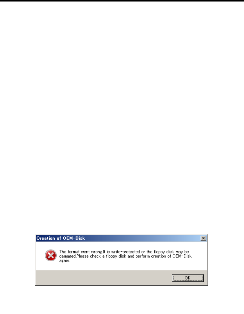
Installing Windows Server 2003 x64 Editions F-5
Create from the menu which appears when running NEC Express5800 Server with
NEC EXPRESSBUILDER.
If you have only NEC Express5800 Server to create Windows Server 2003 x64 Edition OEM-Disk
for EXPRESSBUILDER, use this procedure.
If Windows Server 2003 or Windows can be operated on NEC Express5800 Server, you can use the
other procedure described later.
Follow the steps below.
1. Prepare one Flash FDD or 3.5-inch floppy disk.
2. Turn on your NEC Express5800 Server.
3. Insert the NEC EXPRESSBUILDER DVD into the optical disk drive of the server.
4. Press the RESET switch or press Ctrl, Alt and Delete to reboot the server. (You may also
turn off and then on again to reboot the server.)
The system will boot from the DVD-ROM and NEC EXPRESSBUILDER starts.
5. Select [Create the OEM-Disk for Windows] from [Tools Menu] step.
6. Connect the Flash FDD or insert a floppy disk into the floppy disk drive.
7. Select [Create an Windows Server 2003 x64 Editions OEM-Disk for
EXPRESSBUILDER] at [Create OEM-Disk] and click [Perform].
8. Windows Server 2003 x64 Edition OEM-Disk for EXPRESSBUILDER will be created.
Write-protect and attach a label, then keep it safely.
NOTE: If the following message is displayed, the floppy disk is
write-protected.
Cancel write-protected state.
If you have already cancelled write-protected state, connect the floppy
disk drive again.

F-6 Installing Windows Server 2003 x64 Editions
Create from [Autorun Menu]
This menu requires Microsoft Windows XP, Vista or Windows Server 2003(or later).
You can create Windows Server 2003 x64 Edition OEM-Disk for EXPRESSBUILDER from
[Autorun Menu], if you have the computer on which the above operating systems operate.
Follow the steps below.
1. Prepare one Flash FDD or 3.5-inch floppy disk.
2. Start the Operating System.
3. Insert the NEC EXPRESSBUILDER DVD into the optical disk drive of the server.
The Menu will appear.
4. Connect the Flash FDD or insert the floppy disk into the floppy disk drive.
5. Click [Create drive disk] and select [OEM-Disk for Windows Server 2003 x64 Edition].
NOTE: You can do the same operation with the menu appeared by the
Right-click.
6. Windows Server 2003 x64 Edition OEM-Disk for EXPRESSBUILDER will be created.
Write-protect and attach a label, then keep it safely.

Installing Windows Server 2003 x64 Editions F-7
Windows Server 2003 x64 Editions Clean Installation
This section explains how to perform a clean installation of Windows Server 2003 x64 Editions.
IMPORTANT: If you have created the OEM-Disk into the Flash FDD,
connect the Flash FDD before you start the system.
1. Turn on the system power.
2. Insert the Windows Server 2003 x64 Edition CD-ROM into the optical disk drive.
3. Press Ctrl + Alt + Delete to reset the system.
After a bootable operating system has been installed on the hard disk drive, press Enter
while the message "Press any key to boot from CD..." is displayed at the top of the screen.
If no bootable operating system exists on the hard disk drive, this step is unnecessary.
The Windows Server 2003 x64 Editions setup screen will appear.
If the screen is not displayed, Enter was not pressed properly.
Begin after turning on the system power again.
4. If the RAID Controller is used, press F6 in a few seconds when the window is in either of
the following states.
– "Setup is inspecting your computer's hardware configuration ..." or "Press F6 if you
need to install a third party SCSI or RAID driver..." is displayed.
– A screen with a solid blue background is displayed.
IMPORTANT:
If the RAID Controller is not used, you do not need to press F6.
There is no visible indication on screen when F6 has been pressed.
5. The following message is displayed.
Setup could not determine the type of one or more mass storage devices
installed in your system, or you have chosen to manually specify an adapter.
Currently, Setup will load support for the following mass storage devices.
If the RAID Controller is used, press S.
If the RAID Controller is not used, go to Step 8.

F-8 Installing Windows Server 2003 x64 Editions
6. The following message is displayed.
Please insert the disk labeled
manufacturer-supplied hardware support disk
into Drive A:
*Press ENTER when ready.
Insert the Windows Server 2003 x64 Edition OEM-Disk for EXPRESSBUILDER into the
floppy disk drive, and press Enter.
A list of mass storage devices is displayed.
NOTE: If you use the Flash FDD, the message above is not displayed.
7. Select the proper RAID Controller and press Enter.
The screen of Step 5 is displayed.
– [LSI MegaRAID SAS RAID Controller Driver (Server 2003 for x64)]
(When N8103-116A/117A RAID Controller is installed.)
– [Promise SuperTrak EX Family Controller -64bits platform]
(When N8103-109 RAID Controller is installed.)
– [LSI Embedded MegaRAID (Windows XP/2003 64-bit)]
(When Onboard RAID Controller (LSI Embedded MegaRAID™) is used.)
8. <If the SCSI Controller N8103-75/107 is connected>
Press S.
IMPORTANT:
Insert the Windows Server 2003 x64 Edition OEM-Disk for
EXPRESSBUILDER into the floppy disk drive. If the floppy disk
drive has already contained Windows Server 2003 x64 Edition
OEM-Disk for EXPRESSBUILDER, you do not need to insert the
Windows Server 2003 x64 Edition OEM-Disk for
EXPRESSBUILDER.
If you have created the OEM-Disk into the Flash FDD, connect the
Flash FDD before you start the system.
The screen of Step 6 is displayed. Press Enter, and go to Step 9.
<If the SCSI Controller N8103-75/107 is not connected>
Go to Step 10.

Installing Windows Server 2003 x64 Editions F-9
9. A list of mass storage devices is displayed.
Select the [Adaptec Ultra320 SCSI Cards (Windows 64-bit)] and press Enter.
IMPORTANT: If the following message is displayed when you use
the N8103-75/107 SCSI controller, press S.
T
he driver you provided seems to be newe
r
than the Windows default driver.
Windows already has a driver that you can use
for "Adaptec Ultra 320 SCSI Cards
(Windows64-bit)"
Unless the device manufacturer prefers that
y
ou usethe driver on the floppy disk, you
should use the driver in Windows.
The screen of Step 5 is displayed.
Go to Step 10.
10. <If the SAS Controller N8103-104A is connected>
Press S.
IMPORTANT:
Insert the Windows Server 2003 x64 Edition OEM-Disk for
EXPRESSBUILDER into the floppy disk drive. If the floppy disk
drive has already contained Windows Server 2003 x64 Edition
OEM-Disk for EXPRESSBUILDER, you do not need to insert the
Windows Server 2003 x64 Edition OEM-Disk for
EXPRESSBUILDER.
If you have created the OEM-Disk into the Flash FDD, connect the
Flash FDD before you start the system.
The screen of Step 6 is displayed. Press Enter, and go to Step 11.
<If the SAS Controller N8103-104A is not connected>
Press Enter, and go to Step 12.
11. A list of mass storage devices is displayed.
Select the [LSI Fusion-MPT SAS Driver (Server 2003 x64)] and press Enter.
The screen of Step 5 is displayed.
Press Enter, and go to Step 12.
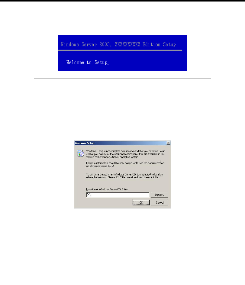
F-10 Installing Windows Server 2003 x64 Editions
12. When the following message is shown, press Enter to start "Welcome to Setup".
IMPORTANT: If you install Windows Server 2003 x64 Editions on
the hard disk larger than 2,097,152MB (2TB), you can specify only a
value equal to or less than 2,097,152MB as partition size.
13. When the installation of Windows Server 2003 x64 Edition has finished, the system
reboots automatically.
14. The [Windows Setup] screen will be displayed after logged on to the system.
IMPORTANT:
In this case, the [Windows Setup] screen may not be displayed.
Be sure to install Microsoft Windows Server 2003 R2 x64 Edition
DISC 2 according to the following procedures.
You can install Microsoft Windows Server 2003 R2 x64 Edition
DISC 2 after the application of "System update".
Be sure to install Microsoft Windows Server 2003 R2 x64 Edition
DISC 2.
In this case, note that the [Windows Setup] screen is not displayed.
15. Insert Microsoft Windows Server 2003 R2 x64 Edition DISC 2 CD-ROM into the optical
disk drive.
Confirm the parameters and click [OK].
16. When the installation has completed, remove Microsoft Windows Server 2003 R2 x64
Edition DISC 2 CD-ROM from the optical disk drive, and restart the system.
After installation is completed, be sure to execute the tasks described in "Driver
Installation and Advanced Settings" and "Updating the System" of this chapter.

Installing Windows Server 2003 x64 Editions F-11
Procedure for License Authentication
Product Key used in the procedure for license authentication should be matched with the COA label
in which the product key contained in Windows Server 2003 x64 Editions is written.
NOTES:
Execute the activation within 30 days. System may be locked after
30 days is passed.
COA label may be attached to your server.

F-12 Installing Windows Server 2003 x64 Editions
Updating the System - Applying Service Pack
-
Update the system in the situation below:
CPU is expanded (expanded to single processor to multi-processor).
Modified system configuration.
Recovered the system using recovery process.
The system update brings the correction program provided by Microsoft to be applied to reinforce
the system security. The system update is recommended.
It is necessary to use ServicePack2 or more. ServicePack 2 need not be applied again when
Windows Server 2003 x64 Editions CD-ROM where ServicePack 2 is included is used and it is
installed.
If you install Windows Server 2003 x64 Editions CD-ROM which contains Service Pack 2, you do
not have to apply "Hotfix for Windows x64" or "Hotfix for Windows Server 2003 (KB921411)".
Go to the section of "Updating the System".
Perform "Updating the System" and application of the "Hotfix (KB921411)".
IMPORTANT: In the situation below, make sure to apply "Updating
the System" and "Hotfix (KB921411)".
Modified system configuration
Recovered the system using recovery process.
NOTES:
If you use Windows Server 2003 x64 Editions CD-ROM which
includes Service Pack 2, the application of "Hotfix (KB921411)" is
not required.
A computer may stop responding on the Resuming Windows screen
when the computer resumes from hibernation if running an
x64-based version of Windows.
Consider the following scenario:
* A computer has three or more processors.
* X64-based version of Windows that is older than Service Pack 2.
In this scenario, the computer may stop responding on the
Resuming Windows screen.
When the computer resumes from hibernation, the program to
correct the problem of Service Pack 2 or KB902839 (*) is
necessary.
(*) KB902839 can be obtained as follows.
http://support.microsoft.com/kb/902839
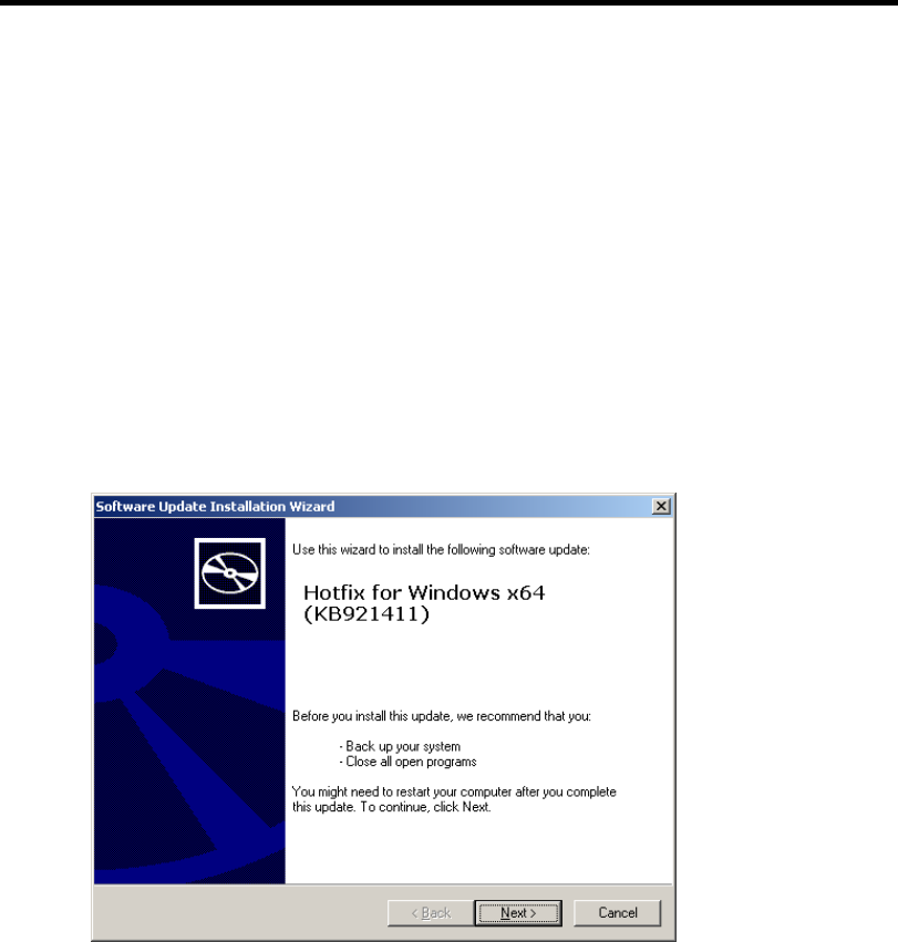
Installing Windows Server 2003 x64 Editions F-13
Application Process of the Hotfix (KB921411)
Apply the "Hotfix (KB921411)" before execute "Updating the System".
1. Log on to the system by the account with administrator authority to the server (such as
administrator).
2. Insert the NEC EXPRESSBUILDER DVD into the optical disk drive of the server.
3. Click Start menu and [Run], and then execute the following command.
<When Windows Server 2003 x64 Editions is used>
\015\win\winnt\w2k3amd\qfe\enu\kb921411.exe
4. When the following message is displayed, click [Next].
After that, follow the message to continue the process.
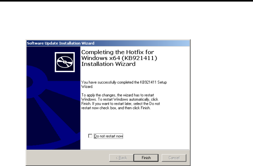
F-14 Installing Windows Server 2003 x64 Editions
5. When the following message is displayed, make sure to click [Finish] to restart the
system.
With that, application process of the Hotfix (KB921411) is finished.
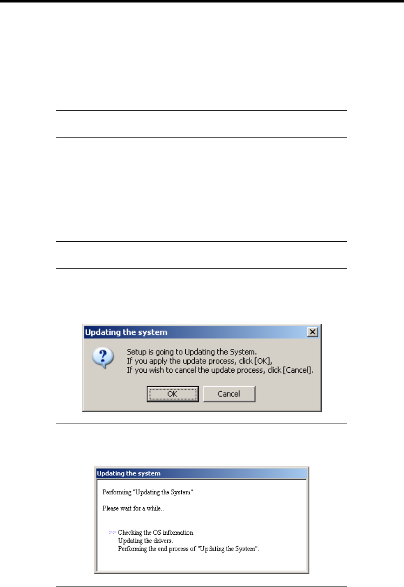
Installing Windows Server 2003 x64 Editions F-15
Application Process of "Updating the System"
"Updating the System" applies the drivers necessary for NEC Express5800 Series.
Follow this process after Hotfix for Windows x64 (KB921411) or Hotfix for Windows Server 2003
(KB921411) had been applied.
NOTE: If you install Windows CD-ROM that contains Service Pack 2
to your system, you do not have to apply Service pack 2 again.
1. Log on to the system with the account that has administrative privilege
(e.g.administrator).
2. Insert the NEC EXPRESSBUILDER DVD into the optical disk drive of server.
The Autorun Menu will be displayed
3. Left-click on [Setup Windows], and then click [Update the system].
NOTE: Right-clicking on the Autorun Menu produces the same
outcome.
4. Follow the message of the screen to proceed the application.
[OK] dialog box will be displayed.
NOTE: The following box appears during the update if you have
deployed a full installation of Windows Server 2003 x64 Edition.
Wait until the update completes.
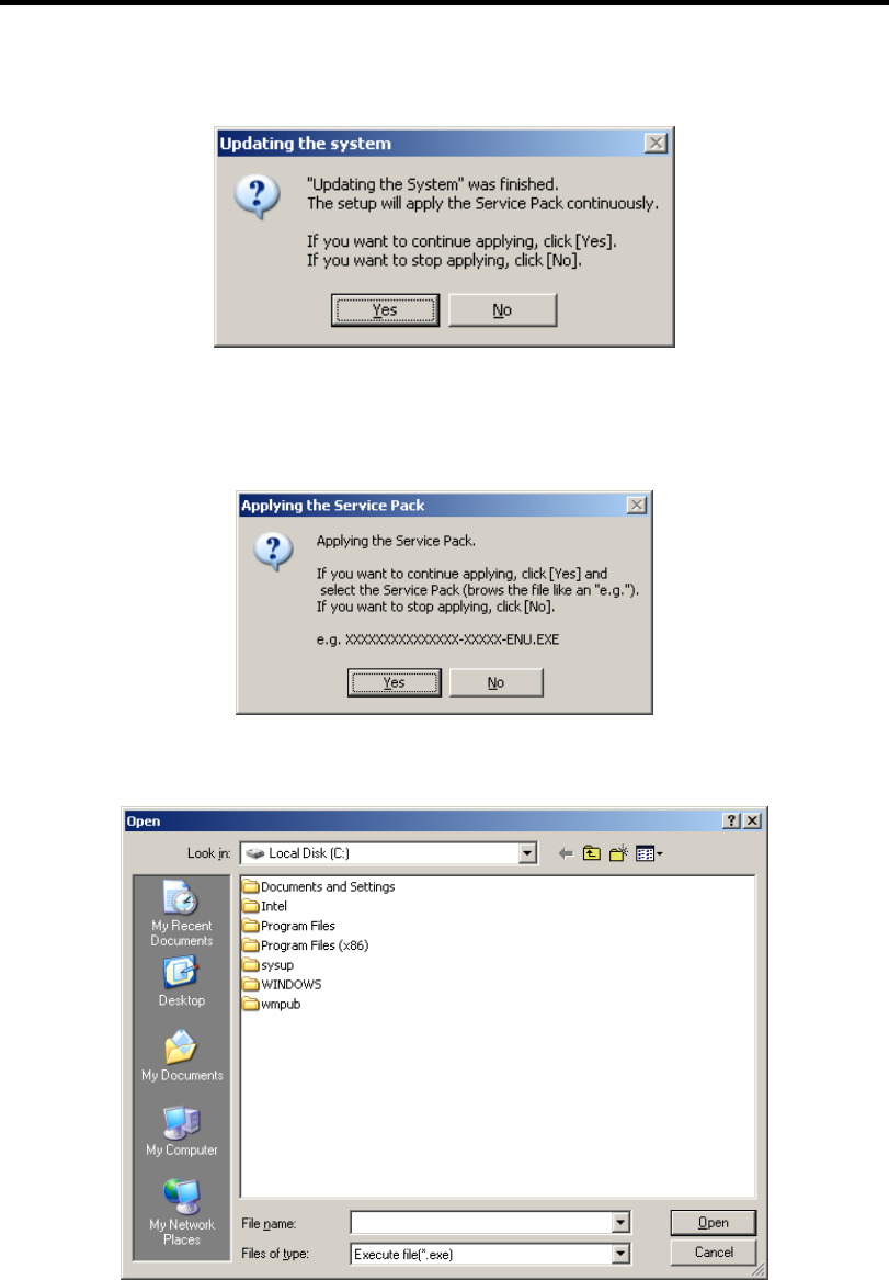
F-16 Installing Windows Server 2003 x64 Editions
5. When the following message appears, "Updating the System" was finished.
When you apply Service Pack: Click [Yes], and then go to Step 6.
When you don't apply Service Pack: Click [No], and then go to Step 8.
6. When the following message appears, click [Yes].
7. When the following message appears, select a Service Pack and click [Open] and then,
according to a message, apply it.
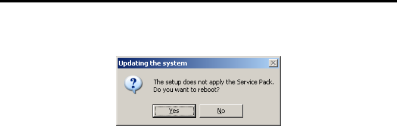
Installing Windows Server 2003 x64 Editions F-17
8. When the following message appears, click [Yes] to restart the system.
The system has been updated.

F-18 Installing Windows Server 2003 x64 Editions
Recovery Process
If "Updating the System" is executed before the application of the "Hotfix for Windows x64
(KB921411)", "!" may be displayed on the USB root hub.
If "!" is displayed on the USB root hub, perform application of the "Hotfix for Windows x64
(KB921411)" and the "Updating the System" according to the following process.
1. Start the Windows Explorer, and click [Tools] and [Folder Options].
2. Select [Files and Folders] - [Hidden files and folders] - [Show hidden files and folders]
radio button from Advanced settings in the [View] tab.
3. Check off the following check box in the [Files and Folders] from Advanced settings in
the [View] tab, and then click [OK].
Hide extensions for know file type
Hide protected operating system files [Recommended]
When the message "You have chosen to display protected operating system files..." is
displayed, click [Yes].
4. Make sure of the files.
Open "<System drive:>\WINDOWS\system32\drivers" directory, and make sure
usbhub.sys and usbport.sys are exists in the directory.
If you can not found them, copy the files according to the following process.
(1) Open "<System drive:>\WINDOWS\system32\dllcache" directory.
(2) Copy usbhub.sys and usbport.sys from the directory noted above to
"<Systemdrive:>\WINDOWS\system32\drivers".
5. Restart the system.
6. Refer to [Application process of the Hotfix (KB921411)] and apply the "Hotfix for
Windows x64 (KB921411)".
7. Refer to [Application process of "Updating the System"] and execute "Updating the
System".
8. Restart the system.
With that, process is finished.

Installing Windows Server 2003 x64 Editions F-19
DRIVER INSTALLATION AND ADVANCED SETTINGS
This section describes on how to install and setup various standard drivers mounted on the device.
For the information on installing and setting up the driver that is not described in this section, refer
to the document attached to the driver.
PROSet
NOTE: All of the operation that related to Intel® PROSet is must be
executed by administrator privileges. Operation by [Remote Desktop
Connection] is prohibited.
Without changing any parameter when opened the properties of adapter
teaming, click the [Cancel] button to close the dialog.
Click [OK] button will cause temporary loss of network connectivity.
PROSet is a utility that confirms the function of network contained in network driver.
Utilizing PROSet enables the following items:
Confirm detailed information of the adapter.
Diagnose loop back test, packet transmission test and so on.
Setup of teaming.
Configuring several network adapters as one team provides the server a tolerant environment on any
trouble and enhances throughput between the switches.
PROSet is necessary to utilize these features.

F-20 Installing Windows Server 2003 x64 Editions
Follow the procedure below to install PROSet.
1. Insert the NEC EXPRESSBUILDER DVD into the optical disk drive.
If the autorun menu is displayed, close menu screen.
2. The [Windows Explorer] dialog starts.
* The procedure in the case of the standard start menu
Click Start menu and click [Windows Explorer].
* The procedure in the case of the classic start menu
Click Start menu, point to [Programs], [Accessories] and click [Windows Explorer].
3. Run "dxsetup.exe" in the following directory.
\015\win\winnt\w2k3amd\r148\apps\prosetdx\winx64
The [Intel(R) PROSet - InstallShield Wizard] dialog starts.
4. Click [Next].
5. Choose "I accept the terms in the license agreement" and click [Next].
6. Click [Next].
7. Click [Install].
8. When [InstallShield Wizard Completed] window is displayed, click[Finished].
9. Remove the NEC EXPRESSBUILDER DVD from the optical disk drive, restart the
system.

Installing Windows Server 2003 x64 Editions F-21
Network Driver
Specify the details of network driver.
One standard network driver that is mounted will be installed automatically, but the link speed and
Duplex mode need to be specified manually.
IP addresses is not be able to set when the "Internet Protocol (TCP/IP)" check box OFF.
This phenomenon will occur with the certain condition.
Check ON the "Internet Protocol (TCP/IP)" check box and IP address will be able to set.
When PROSet is not installed
1. Open the [Device Manager].
2. Double-click [(Network Adapter Name)] in the list.
3. Click the [Advanced] and specify the [Link Speed & Duplex] value the same as the value
specified for HUB.
4. Click [OK].
5. Restart the system
When PROSet is installed
1. Open the [Device Manager].
2. Double-click [(Network Adapter Name)] in the list.
3. Click the [Link Speed] and specify the [Speed & Duplex] value the same as the value
specified for HUB.
4. Click [OK].
5. Restart the system
Also, add or delete any protocols and services if necessary.
You can operate the process on the property dialog box for local area network which can be
appeared from [Network and Dial-up Connection].
NOTE: It is recommend to add [Network Monitor] at [Adding
Services]. [Network Monitor] can monitor the frame (or the packet) that
the computer installing [Network Monitor] sends or receives. This tool
is valuable when analyzing network trouble. For information on how to
install the tool, see the "Setting for Solving Problems" described later in
this chapter.
Re-install the Network Driver
The network driver will be installed automatically.

F-22 Installing Windows Server 2003 x64 Editions
Optional Network Board Driver
If you want to use optional Network Board (N8104-111/112/119/120/121/125A/126/123A), the
network driver will be installed automatically. Therefore, the driver attached to the Network board
should not be used.
If you want to use optional Network Board (N8104-111/112/119/120/121/125A/126/123A), install
the driver stored in NEC EXPRESSBUILDER DVD.
In case of using (N8104-111)
"\015\win\winnt\w2k3amd\r148\pro100\winx64\ndis5x"
In case of using (N8104-112/119/120/121/125A/126)
"\015\win\winnt\w2k3amd\r148\pro1000\winx64\ndis5x"
If the procedure of installation is not clear, refer to the installation procedure described in the
section "Installation of the Optional Network Board Driver".
In case of using (N8104-123A)
Please refer to the installation manual provided with the board.
Installation of the Optional Network Board Driver
1. Start Device Manager.
2. Click [Network adapters] and double-click [(Network Adapter Name)].
[(Network Adapter Name) Properties] appears.
NOTE: [(Intel (R) PRO/1000...)] is the name of On-Board adapter. All
other names show the Optional Network Board.
3. Click [Driver] tab and click [Update Driver...]. [Hardware Update Wizard] appears.
4. Select the [Install from a list or specific location (Advanced)] radio button and click
[Next].
5. Select the [Search for the best driver in these locations] radio button and uncheck the
[Search removable media (floppy, CD-ROM...)] check box.
6. Check the [Include this location in the search] check box and when using [(N8104-111)],
specify
[\015\win\winnt\w2k3amd\r148\pro100\winx64\ndis5x].
Then click [Next].
When using [(N8104-112/119/120/121/125A/126)], specify
[\015\win\winnt\w2k3amd\r148\pro1000\winx64\ndis5x].
Then click [Next].
7. Click [Finish].
8. Restart the system

Installing Windows Server 2003 x64 Editions F-23
Setup Team
Adapter Fault Tolerance (AFT) is a feature that creates a group containing more than one adapter
and automatically converts the process of the working adapter to the other adapter in the group
when any trouble occurred on that adapter.
Adaptive Load Balancing (ALB) is a feature that creates a group containing more than one adapter
and enhance the through put by operating packet transmission from the server by all the adapters.
This feature includes AFT feature.
Switch Fault Tolerance (SFT) is a feature that provides a failover relationship between two ports
when each port is connected to a separate switch.
SFT supports two ports per team.
Static Link Aggregation (SLA) accounts for the GEC and 802.3ad static protocols.
SLA is a switch-assisted teaming mode and requires configuring ports at both ends of the link:
server interfaces and switch ports.
IMPORTANT:
AFT/ALB setup must be operated after installing the
drivers/PROSet and restarting the system.
All the adapters specified as a group of Adapter Teaming must exist
on the same LAN. If they are connected to the separate switches,
they will not work normally.
The adapters specified as a group of Adaptive Load Balancing
(ALB) can be connected to only Switching Hub.
When exchange the mother board or option network card, make sure
to remove the adapter team before exchanges and recreate the
adapter team after exchange complete.
Confirm the port setting of switching hub (L2) matches the server
network adapter Teaming mode.
Create Team
1. Open the [Device Manager].
2. Open [Network adapters] → [Intel(R) xxx] properties.
3. Click [Teaming] tab and check the [Team this adapter with other adapters] check box.
Click [New Team].
4. Fill the name of the team in [Specify a name for the team] and click [Next].
5. Include the adapter to the team and click [Next].

F-24 Installing Windows Server 2003 x64 Editions
6. Select a team mode, and then click [Next].
IMPORTANT: Following team types are supported.
Adapter Fault Tolerance
Adaptive Load Balancing
Static Link Aggregation
Switch Fault Tolerance
7. Click [Finish].
8. Click [TEAM: "Team name"] from [Device manager] → [Network adapters] to modify
the team. Click [Settings] tab and click [Modify Team] button.
9. Refer to the following procedure to set the team member adapter priority status.
– Set Primary
Point the adapter and click [Set Primary] button.
– Set Secondary
Point the adapter and click [Set Secondary] button.
NOTE: Adapter priority config can be confirmed by the following
procedure:
1. Click [TEAM: "Team name"] from [Device manager] → [Network
adapters].
2. Click [Settings] and confirm Adapters in team list.
10. Click [Test Switch] → [Run test] to confirm the adapter team is properly setup.
Confirm the result in [Test results].
11. Restart the system
Remove Team
1. Open the [Device Manager].
2. Click [Network adapters], and open [TEAM: "Team name"] properties.
3. Click [Setting] tab.
4. Click [Remove Team] button.
5. Click [Yes] to the message.
6. Confirm [TEAM: "Team name"] adapter in not existing in [Network adapters] tree and
reboot the system.

Installing Windows Server 2003 x64 Editions F-25
Setting WOL
Refer to the following procedure to enable WOL.
When PROSet is not installed
1. Start Device Manager.
2. Point to [Network adapters] and double click [Intel(R) 82547L Gigabit Network
Connection] to open the adapter [Properties].
3. Click [Power Management] tab and change setting in [Wake On LAN] according to the
following list.
Setting item Change setting
"Allow the computer to turn off this device to save power" ON
"Allow this device to bring the computer out of standby" ON or OFF
IMPORTANT:
■ Set "Allow this device to bring..." to "ON", WOL by
DirectedPacket(*1) or MagicPacket will be available on Standby
state.
■ WOL by DirectedPacket is not available on Hibernate and
Shutdown state.
(*1) Packet with the Ethernet address of the adapter in ethernet header
or Packet with an IP address assigned to the adapter in IP header.
4. Click [Advanced] tab and point to [Enable PME].
5. Set the "Enable" in [Value].
6. Click [OK].
7. Restart the system

F-26 Installing Windows Server 2003 x64 Editions
When PROSet is installed
1. Start Device Manager.
2. Point to [Network adapters] and double click [Intel(R) 82547L Gigabit Network
Connection] to open the adapter [Properties].
3. Click [Power Management] tab and change setting in [Wake On LAN] according to the
following list.
Setting item Change setting
"Wake On Directed Packet" ON or OFF
"Wake On Magic Packet" ON
"Wake on Magic Packet from power off state" ON
"Wake on Link" OFF
IMPORTANT: DirectedPacket(*1) will not wake up the system on
Shutdown state even “Wake On Directed Packet” is setting to “ON”.
Only on Sleep or Hibernate state will wake up by a DirectedPacket.
NOTES:
[Power Saver Options] setting is not necessary to change.
Above setting will be maintained until manually resetting are
executed.
IMPORTANT: The parameters of [Wake On LAN] will not exist, if
the network ports are not available for WOL.
4. Click [OK].
5. Restart the system

Installing Windows Server 2003 x64 Editions F-27
Graphics Accelerator Driver
If you utilize standard graphics accelerator drivers, update your system with NEC
EXPRESSBUILDER DVD attached to your system.
Standard graphics accelerator drivers will be installed automatically.
Observe the following procedure when you want to reinstall the driver individually.
1. Insert the NEC EXPRESSBUILDER DVD into the optical disk drive.
If the autorun menu is displayed, close menu screen.
2. Click Start menu, point to [Programs], [Accessories] and click [Windows Explorer].
3. Run "setup.exe" in the following directory.
\015\win\winnt\w2k3amd\video
4. Follow the message to continue the installation.
If the dialog message "Digital Signature could not been found." appears, select [Yes] to
continue.
5. Remove the NEC EXPRESSBUILDER DVD from the optical disk drive, restart the
system.
Installing SCSI Controller Driver (N8103-75/107)
If you use the SCSI Controller N8103-75/107, update your system with NEC EXPRESSBUILDER
DVD attached to your system.
The SCSI Controller driver will be installed automatically.
Installing SCSI Controller Driver (N8103-95)
If you use the SCSI Controller N8103-95, you do not need to install the driver manually. It is
automatically installed by Windows Plug-and-Play.
Installing SAS Controller Driver (N8103-104A)
If you use the SAS Controller N8103-104A, update your system with NEC EXPRESSBUILDER
DVD attached to your system.
The SAS Controller driver will be installed automatically.
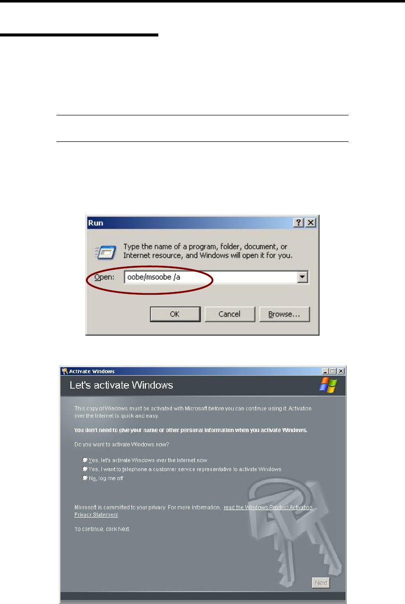
F-28 Installing Windows Server 2003 x64 Editions
About Windows Activation
Windows Server 2003 x64 Editions must be activated before you can use Windows Server 2003 x64
Editions.
Windows activation process is as follows.
NOTE: When you use Windows Server 2003 R2 x64 Editions BackUp
CD-ROM, activation process is not needed.
1. Click [Run] on [Start] menu.
Type as follows in the [Open:] box, and click [OK].
oobe/msoobe /a
2. When the screen as follows is displayed, click [Next].
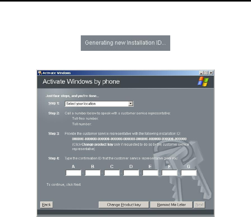
Installing Windows Server 2003 x64 Editions F-29
The following screen is displayed.
3. Process "Windows activation" according to the following message.
SETTING FOR SOLVING PROBLEMS
Set for collecting memory dump using the procedure described in Chapter 5.

F-30 Installing Windows Server 2003 x64 Editions
(This page is intentionally left blank.)

Appendix G
Installing Windows Server 2003
This section explains how to install the Windows Server 2003.
BEFORE INSTALLING WINDOWS SERVER 2003
Read the following notes or information before installing the Windows Server 2003.
Optional Board Supported by NEC EXPRESSBUILDER
The NEC EXPRESSBUILDER DVD attached to your server supports the following optional
boards;
NOTE: If you want to install the other boards by using a driver floppy
disk ("OEM-Disk for Mass storage device"), except ones listed below,
see "Installing with the OEM-Disk for Mass storage device" and
"Installing Optional Mass Storage Driver" of "Parameter File Creator"
in Chapter 6.
Controllers supporting installation of OS with Express Setup
– N8103-109 RAID Controller (128 MB, RAID0/1/5/6)*
– N8103-116A RAID Controller (128 MB, RAID0/1)*
– N8103-117A RAID Controller (128 MB, RAID0/1/5/6)*
– Onboard RAID Controller (LSI Embedded MegaRAID™)
Other controllers
– N8103-75 SCSI Controller*
– N8103-95 SCSI Controller*
– N8103-104A SAS Controller*
– N8103-107 SCSI Controller*
* Option.

G-2 Installing Windows Server 2003
Service Pack Which EXPRESSBUILDER Supports
The NEC EXPRESSBUILDER DVD attached to the server supports following combination of the
OS installation media and Service Pack.
Windows Server 2003 R2
– OS installation media (with Service Pack 2)
– OS installation media (No Service Pack) + Service Pack 2
– OS installation media (No Service Pack)
Application of Service Pack
You can install the Service Pack on the server. When the Service Pack is not attached to your system,
prepare it by yourself.
When installing Windows Server 2003 R2, it is not necessary to apply Service Pack 1.
Updating System
If you modified the Windows system, execute "Update Express5800 system" in the Autorun Menu.
Re-installing to the Hard Disk which has been upgraded to Dynamic
Disk
If you want to leave the existing partition when installing the system on the hard disk upgraded to
Dynamic Disk, note the following issue:
Do not select the partition that OS had been installed as the partition to install the OS newly.
Select "Use the current File System" for the format of OS partition.
Mounting MO Device
Do not mount an MO device on your server during the Windows installation.
About Removable Media
Do not set removable media, such as DAT and LTO, into the device mounted on this computer
during the Windows installation.
Floppy Disk Drive
The internal floppy disk drive is not included in your system at the standard configuration. Prepare
the optional Flash FDD or USB FDD if necessary.

Installing Windows Server 2003 G-3
About the System Partition Size
The size for the partition that the system is to be installed can be calculated from the following
formula.
Size necessary to install the system + Paging File Size + Dump File Size
+ Application Size
Size necessary to install the system = 3500MB (Windows Server 2003 R2)
= 3500MB (Windows Server 2003 R2 with Service
Pack 2)
= 5300MB (Windows Server 2003 R2 + Service Pack
2)
Paging File Size (Recommended) = Mounted Memory Size * 1.5
Dump file Size = Mounted Memory Size + 12MB
Application Size = Required Size
IMPORTANT:
The above-mentioned paging file size is recommended for
collecting debug information (memory dump). The paging file with
initial size large enough to store the dump file in the boot drive is
required.
Correct debug information might not be able to be collected due to
virtual memory shortage when the paging file is insufficient, so set
an enough size of the paging file with the entire system.
The maximum paging file size which can be set on one partition is
4095MB. If the above paging file size exceeds 4095MB, specify
4095MB for the paging file size.
The maximum dump file size for the system with more than 2GB
memory mounted is '2048MB + 12MB'.
If you install any application program or the like, add necessary
space to the partition to install these programs.
For example, if the mounted memory size is 1GB (1,024MB), the partition size will be calculated by
the above formula as follows:
3,500MB + (1,024MB * 1.5) + (1,024MB + 12MB) + Application Size
= 6,072MB + Application Size

G-4 Installing Windows Server 2003
Dividing into the partition of the recommended size into multiple disks as written below will solve
problem that it cannot be reserved in one disk.
1. Set the "Size required for installation + Paging file size".
2. See Chapter 5 and set that debugging information (equivalent to the dump file size) is to
be written to a separate disk.
(If the disk does not have enough free space to enable the dump file size to be written,
then after installing the system using the "Size required for installation + Paging file size",
install an additional new disk.)

Installing Windows Server 2003 G-5
INSTALLING WINDOWS SERVER 2003
Preparations for Installation
NEC EXPRESSBUILDER DVD
Microsoft Windows Server 2003 R2 Standard Edition (CD-ROM)
Windows Server 2003 Service Pack (CD-ROM)
User's Guide
Getting Started
Windows Server 2003 OEM-Disk for EXPRESSBUILDER
Creating "Windows Server 2003 OEM-Disk for EXPRESSBUILDER"
Before installing, create Windows Server 2003 OEM-Disk for EXPRESSBUILDER.
NOTE: If you have already "Windows Server 2003 OEM-Disk for
EXPRESSBUILDER" for NEC Express5800 Server which you are
going to install Windows Server 2003, you do not need to create it
again.
You can create Windows Server 2003 OEM-Disk for EXPRESSBUILDER with the following two
procedures.
Create from the menu which appears when running NEC Express5800 Server with
NEC EXPRESSBUILDER.
If you have only NEC Express5800 Server to create Windows Server 2003 OEM-Disk for
EXPRESSBUILDER, use this procedure.
If Windows Server 2003 or Windows can be operated on NEC Express5800 Server, you can use the
other procedure described later.
Follow the steps below.
1. Prepare one Flash FDD or 3.5-inch floppy disk.
2. Turn on your NEC Express5800 Server.
3. Insert the NEC EXPRESSBUILDER DVD into the optical disk drive of the server.
4. Press the RESET switch or press Ctrl, Alt and Delete to reboot the server. (You may also
turn off and then on again to reboot the server.)
The system will boot from the DVD-ROM and NEC EXPRESSBUILDER starts.
5. Select [Create the OEM-DISK for Windows] from [Tools Menu] step.
6. Connect the Flash FDD or insert a floppy disk into the floppy disk drive.
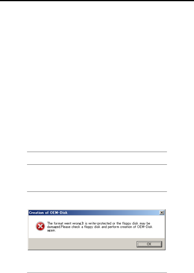
G-6 Installing Windows Server 2003
7. Select [Create a Windows Server 2003 OEM-Disk for EXPRESSBUILDER] at [Create
OEM-Disk] and click [Perform].
8. Windows Server 2003 OEM-Disk for EXPRESSBUILDER will be created.
Write-protect and attach a label, then keep it safely.
Create from [Autorun Menu]
This menu requires Microsoft Windows XP, Vista or Windows Server 2003 (or later).
You can create Windows Server 2003 OEM-Disk for EXPRESSBUILDER from [Autorun Menu], if
you have the computer on which the above operating systems operate.
Follow the steps below.
1. Prepare one Flash FDD or 3.5-inch floppy disk.
2. Start the Operating System.
3. Insert the NEC EXPRESSBUILDER DVD into the optical disk drive of the server.
The Menu will appear.
4. Connect the Flash FDD or insert a floppy disk into the floppy disk drive.
5. Click [Create drive disk] and select [OEM-Disk for Windows Server 2003].
NOTE: You can do the same operation with the menu appeared by the
Right-click.
6. Windows Server 2003 OEM-Disk for EXPRESSBUILDER will be created.
Write-protect and attach a label, then keep it safely.
NOTE: If the following message is displayed, the floppy disk is
write-protected.
Cancel write-protected state.
If you have already cancelled write-protected state, connect the floppy
disk drive again.

Installing Windows Server 2003 G-7
Windows Server 2003 Clean Installation
This section explains how to perform a clean installation of Windows Server 2003.
IMPORTANT: If you have created the OEM-Disk into the Flash FDD,
connect the Flash FDD before you start the system.
1. Turn on the system power.
2. Insert the Windows Server 2003 CD-ROM into the optical disk drive.
3. Press Ctrl + Alt + Delete to reset the system.
After a bootable operating system has been installed on the hard disk drive, press Enter
while the message "Press any key to boot from CD..." is displayed at the top of the screen.
If no bootable operating system exists on the hard disk drive, this step is unnecessary.
The Windows Server 2003 setup screen will appear.
If the screen is not displayed, Enter was not pressed properly.
Begin after turning on the system power again.
4. If the RAID Controller is used, press F6 in a few seconds when the window is in either of
the following states.
– "Setup is inspecting your computer's hardware configuration ..." or "Press F6 if you
need to install a third party SCSI or RAID driver..." is displayed.
– A screen with a solid blue background is displayed.
IMPORTANT:
If the RAID Controller is not used, you do not need to press F6.
There is no visible indication on screen when F6 has been pressed.
5. The following message is displayed.
Setup could not determine the type of one or more mass storage devices
installed in your system, or you have chosen to manually specify an adapter.
Currently, Setup will load support for the following mass storage devices.
If the RAID Controller is used, press S.
If the RAID Controller is not used, go to Step 8.

G-8 Installing Windows Server 2003
6. The following message is displayed.
Please insert the disk labeled
manufacturer-supplied hardware support disk
into Drive A:
*Press ENTER when ready.
Insert the Windows Server 2003 OEM-Disk for EXPRESSBUILDER into the floppy disk
drive, and press Enter.
A list of mass storage devices is displayed.
NOTE: If you use the Flash FDD, the message above is not displayed.
7. Select the proper RAID Controller and press Enter.
The screen of Step 5 is displayed.
– [LSI MegaRAID SAS RAID Controller Driver (Server 2003 32-bit)]
(When N8103-116A/117A RAID Controller is installed.)
– [Promise SuperTrak EX SAS RAID Controller -32bits platform]
(When N8103-109 RAID Controller is installed.)
– [LSI Embedded MegaRAID (Windows XP/2003)]
(When Onboard RAID Controller (LSI Embedded MegaRAID™) is used.)
8. <If the SCSI Controller N8103-75/107 is connected>
Press S.
IMPORTANT:
Insert the Windows Server 2003 OEM-Disk for
EXPRESSBUILDER into the floppy disk drive. If the floppy disk
drive has already contained Windows Server 2003 OEM-Disk for
EXPRESSBUILDER, you do not need to insert the Windows Server
2003 OEM-Disk for EXPRESSBUILDER.
If you have created the OEM-Disk into the Flash FDD, connect the
Flash FDD before you start the system.
The screen of Step 6 is displayed. Press Enter, and go to Step 9.
<If the SCSI Controller N8103-75/107 is not connected>
Go to Step 10.

Installing Windows Server 2003 G-9
9. A list of mass storage devices is displayed.
Select the [Adaptec Ultra320 SCSI Cards (Windows 32-bit)] and press Enter.
IMPORTANT: If the following message is displayed when you use
the N8103-75/107 SCSI controller, press S.
T
he driver you provided seems to be newe
r
than the Windows default driver.
Windows already has a driver that you can use
for "Adaptec Ultra320 SCSI Cards (Windows
32-bit)"
Unless the device manufacturer prefers that
y
ou use the driver on the floppy disk, you
should use the driver in Windows.
The screen of Step 5 is displayed.
Go to Step 10.
10. <If the SCSI Controller N8103-95 is connected>
Press S.
IMPORTANT:
Insert the Windows Server 2003 OEM-Disk for
EXPRESSBUILDER into the floppy disk drive. If the floppy disk
drive has already contained Windows Server 2003 OEM-Disk for
EXPRESSBUILDER, you do not need to insert the Windows Server
2003 OEM-Disk for EXPRESSBUILDER.
If you have created the OEM-Disk into the Flash FDD, connect the
Flash FDD before you start the system.
The screen of Step 6 is displayed. Press Enter, and go to Step 11.
<If the SCSI Controller N8103-95 is not connected>
Go to Step 12.

G-10 Installing Windows Server 2003
11. A list of mass storage devices is displayed.
Select the [Adaptec Ultra160 SCSI Cards (Win Server 2003)] and press Enter.
IMPORTANT: If the following message is displayed when you use
the N8103-95 SCSI controller, press S.
T
he driver you provided seems to be newe
r
than the Windows default driver.
Windows already has a driver that you can use
for "Adaptec Ultra 160 SCSI Cards (Win Serve
r
2003)"
Unless the device manufacturer prefers that
y
ou use the driver on the floppy disk, you
should use the driver in Windows.
The screen of Step 5 is displayed.
Go to Step 12.
12. <If the SAS Controller N8103-104A is connected>
Press S.
IMPORTANT:
Insert the Windows Server 2003 OEM-Disk for
EXPRESSBUILDER into the floppy disk drive. If the floppy disk
drive has already contained Windows Server 2003 OEM-Disk for
EXPRESSBUILDER, you do not need to insert the Windows Server
2003 OEM-Disk for EXPRESSBUILDER.
If you have created the OEM-Disk into the Flash FDD, connect the
Flash FDD before you start the system.
The screen of Step 6 is displayed. Press Enter, and go to Step 13.
<If the SAS Controller N8103-104A is not connected>
Press Enter, and go to Step 14.
13. A list of mass storage devices is displayed.
Select the [LSI Fusion-MPT SAS Driver (Server 2003 32-bit)] and press Enter.
The screen of Step 5 is displayed.
Press Enter, and go to Step 14.
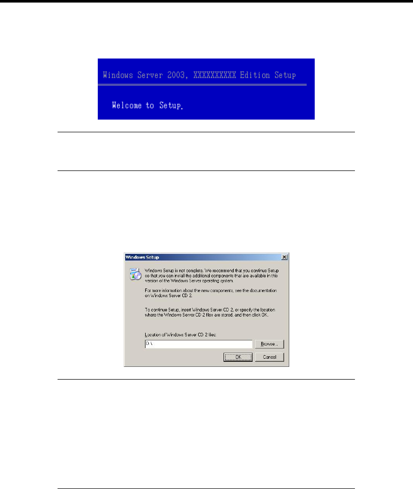
Installing Windows Server 2003 G-11
14. When the following message is shown, press Enter to start "Welcome to Setup".
IMPORTANT: If you install Windows Server 2003 on the hard disk
larger than 2,097,152MB(2TB), you can specify only a value equal to
or less than 2,097,152MB as partition size.
15. When the installation of Windows Server 2003 has finished, the system reboots
automatically.
16. When Windows Server 2003 R2 has been installed, the [Windows Setup] screen will be
displayed after logged on to the system.
IMPORTANT:
In this case, the [Windows Setup] screen may not be displayed.
Be sure to install Microsoft Windows Server 2003 R2 DISC 2
according to the following procedures.
You can install Microsoft Windows Server 2003 R2 DISC 2 after
the application of "System update".
Be sure to install Microsoft Windows Server 2003 R2 DISC 2.
In this case, note that the [Windows Setup] screen is not displayed.
17. Insert Microsoft Windows Server 2003 R2 DISC 2 CD-ROM into the optical disk drive.
Confirm the parameters and click [OK].
18. When the installation has completed, remove Microsoft Windows Server 2003 R2 DISC 2
CD-ROM from the optical disk drive, and restart the system.
19. When the installation has completed, be sure to execute the tasks described in "Driver
Installation and Advanced Settings" and "Updating the System" of manual.

G-12 Installing Windows Server 2003
Procedure for License Authentication
Product Key used in the procedure for license authentication should be matched with the COA label
in which the product key contained in Windows Server 2003 is written.
NOTES:
Execute the activation within 30 days. System may be locked after
30 days is passed.
COA label may be attached to your server.
Updating the System - Applying Service Pack -
Update the system in the situation below:
CPU is expanded (expanded to single processor to multi-processor).
Modified system configuration.
Recovered the system using recovery process.
The system update brings the correction program provided by Microsoft to be applied to reinforce
the system security. The system update is recommended.
Service Pack 2 need not be applied again when Windows Server 2003 CD-ROM which Service
Pack 2 is included is used and it is installed.
Go to the section of "Updating the System".
Perform "Updating the System" and application of the "Hotfix (KB921411)".
IMPORTANT: In the situation below, make sure to apply "Updating
the System" and "Hotfix (KB921411)".
Modified system configuration
Recovered the system using recovery process.
NOTE:
If you use Windows Server 2003 CD-ROM which includes Service
Pack 2, the application of "Hotfix (KB921411)" is not required.
Application Process of the Hotfix (KB921411)
Apply the "Hotfix (KB921411)" before execute "Updating the System".
1. Log on to the system by the account with administrator authority to the server (such as
administrator).
2. Insert the NEC EXPRESSBUILDER DVD into the optical disk drive of the server.
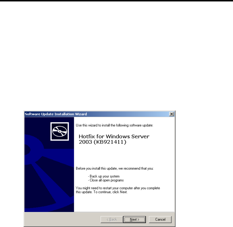
Installing Windows Server 2003 G-13
3. Click Start menu and [Run], and then execute the following command.
<When the English version of Windows Server 2003 R2 is used>
\015\win\winnt\dotnet\qfe\enu\kb921411.exe
<When the Simplified Chinese version of Windows Server 2003 R2 is used>
\015\win\winnt\dotnet\qfe\chs\kb921411.exe
<When the Traditional Chinese version of Windows Server 2003 R2 is used>
\015\win\winnt\dotnet\qfe\cht\kb921411.exe
4. When the following message is displayed, click [Next].
After that, follow the message to continue the process.
5. When the following message is displayed, make sure to click [Finish] to restart the
system.
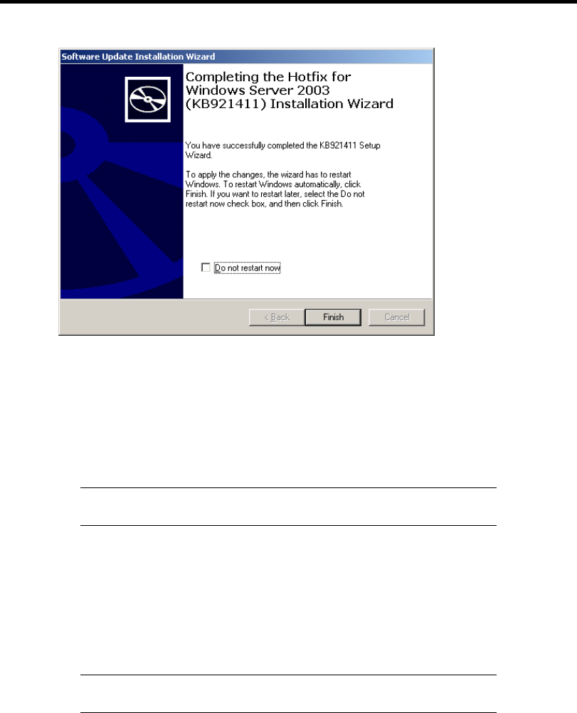
G-14 Installing Windows Server 2003
With that, application process of the Hotfix (KB921411) is finished.
Application Process of "Updating the System"
"Updating the System" applies the drivers necessary for NEC Express5800 Series.
Follow this process after Hotfix for Windows Server 2003 (KB921411) had been applied.
NOTE: If you install Windows CD-ROM that contains Service Pack 2
to your system, you do not have to apply Service pack 2 again.
1. Log on to the system with the account that has administrative privilege (e.g.
administrator).
2. Insert the NEC EXPRESSBUILDER DVD into the optical disk drive of server.
The Autorun Menu will be displayed
3. Left-click on [Setup Windows], and then click [Update the system].
NOTE: Right-clicking on the Autorun Menu produces the same
outcome.
4. Follow the message of the screen to proceed the application.
[OK] dialog box will be displayed.
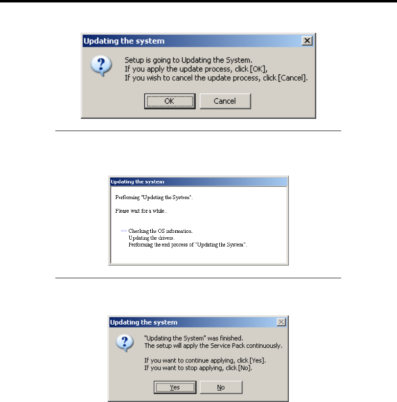
Installing Windows Server 2003 G-15
NOTE: The following box appears during the update if you have
deployed a full installation of Windows Server 2003.
Wait until the update completes.
5. When the following message appears, "Updating the System" was finished.
When you apply Service Pack: Click [Yes], and then go to Step 6.
When you don't apply Service Pack: Click [No], and then go to Step 8.
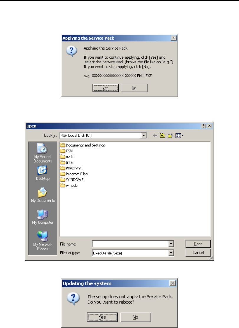
G-16 Installing Windows Server 2003
6. When the following message appears, click [Yes].
7. When the following message appears, select a Service Pack and click [Open] and then,
according to a message, apply it.
8. When the following message appears, click [Yes] to restart the system.
The system has been updated.

Installing Windows Server 2003 G-17
Recovery Process
If "Updating the System" is executed before the application of the "Hotfix for Windows Server 2003
(KB921411)", "!" may be displayed on the USB root hub.
If "!" is displayed on the USB root hub, perform application of the "Hotfix for Windows Server
2003 (KB921411)" and the "Updating the System" according to the following process.
1. Start the Windows Explorer, and click [Tools] and [Folder Options].
2. Select [Files and Folders] - [Hidden files and folders] - [Show hidden files and folders]
radio button from Advanced settings in the [View] tab.
3. Check off the following check box in the [Files and Folders] from Advanced settings in
the [View] tab, and then click [OK].
Hide extensions for know file type
Hide protected operating system files [Recommended]
When the message "You have chosen to display protected operating system files..." is
displayed, click [Yes].
4. Make sure of the files.
Open "<System drive:>\WINDOWS\system32\drivers" directory, and make sure
usbhub.sys and usbport.sys are exists in the directory.
If you can not found them, copy the files according to the following process.
(1) Open "<System drive:>\WINDOWS\system32\dllcache" directory.
(2) Copy usbhub.sys and usbport.sys from the directory noted above to
"<Systemdrive:>\WINDOWS\system32\drivers".
5. Restart the system.
6. Refer to [Application process of the Hotfix (KB921411)] and apply the "Hotfix for
Windows Server 2003 (KB921411)".
7. Refer to [Application process of "Updating the System"] and execute "Updating the
System".
8. Restart the system.
With that, process is finished.

G-18 Installing Windows Server 2003
DRIVER INSTALLATION AND ADVANCED SETTINGS
This section describes on how to install and setup various standard drivers mounted on the device.
For the information on installing and setting up the driver that is not described in this section, refer
to the document attached to the driver.
PROSet
PROSet is a utility that confirms the function of network contained in network driver.
Utilizing PROSet enables the following items:
Confirm detailed information of the adapter.
Diagnose loop back test, packet transmission test and so on.
Setup of teaming.
Configuring several network adapters as one team provides the server a tolerant environment on any
trouble and enhance throughput between the switches.
PROSet is necessary to utilize these features.
Follow the procedure below to install PROSet.
1. Insert the NEC EXPRESSBUILDER DVD into the optical disk drive.
If the autorun menu is displayed, close menu screen.
2. The [Windows Explorer] dialog starts.
* The procedure in the case of the standard start menu
Click Start menu and click [Windows Explorer].
* The procedure in the case of the classic start menu
Click Start menu, point to [Programs], [Accessories] and click [Windows Explorer].
3. Run "dxsetup.exe" in the following directory.
\015\win\winnt\dotnet\r148\apps\prosetdx\win32
The [IntelR PROSet - InstallShield Wizard] dialog starts.
4. Click [Next].
5. Choose "I accept the terms in the license agreement" and click [Next].
6. Click [Next].
7. Click [Install].
8. When [InstallShield Wizard Completed] window is displayed, click [Finished].
9. Remove the NEC EXPRESSBUILDER DVD from the optical disk drive, restart the
system.

Installing Windows Server 2003 G-19
Network Driver
Specify the details of network driver.
One standard network driver that is mounted will be installed automatically, but the link speed and
Duplex mode need to be specified manually.
When PROSet is not installed
1. Open the [Device Manager].
2. Double-click [(Network Adapter Name)] in the list.
3. Click the [Advanced] and specify the [Link Speed & Duplex] value the same as the value
specified for HUB.
4. Click [OK].
5. Restart the system
When PROSet is installed
1. Open the [Device Manager].
2. Double-click [(Network Adapter Name)] in the list.
3. Click the [Link Speed] and specify the [Speed & Duplex] value the same as the value
specified for HUB.
4. Click [OK].
5. Restart the system
Also, add or delete any protocols and services if necessary.
You can operate the process on the property dialog box for local area network which can be
appeared from [Network and Dial-up Connection].
NOTE: We recommend you to add [Network Monitor] at [Adding
Services]. [Network Monitor] can monitor the frame (or the packet) that
the computer installing [Network Monitor] sends or receives. This tool
is valuable when analyzing network trouble. For information on how to
install the tool, see the "Setup for Trouble Process" later in this
document.
Optional Network Board Driver
See Chapter 5, "Optional Network Board Driver" for re-installing the optional network board driver.

G-20 Installing Windows Server 2003
Setup Team
See Chapter 5, "Setup Team" for re-setting the Team.
Setting WOL
Refer to the following procedure to enable WOL.
When PROSet is not installed
1. Start Device Manager.
2. Point to [Network adapters] and double click [Intel(R) 82547L Gigabit Network
Connection] to open the adapter [Properties].
3. Click [Power Management] tab and change setting in [Wake On LAN] according to the
following list.
Setting item Change setting
"Allow the computer to turn off this device to save power" ON
"Allow this device to bring the computer out of standby" ON or OFF
IMPORTANT:
■ Set "Allow this device to bring..." to "ON", WOL by
DirectedPacket(*1) or MagicPacket will be available on Standby
state.
■ WOL by DirectedPacket is not available on Hibernate and
Shutdown state.
(*1) Packet with the Ethernet address of the adapter in ethernet header
or Packet with an IP address assigned to the adapter in IP header.
4. Click [Advanced] tab and point to [Enable PME].
5. Set the "Enable" in [Value].
6. Click [OK].
7. Restart the system

Installing Windows Server 2003 G-21
When PROSet is installed
1. Start Device Manager.
2. Point to [Network adapters] and double click [Intel(R) 82547L Gigabit Network
Connection] to open the adapter [Properties].
3. Click [Power Management] tab and change setting in [Wake On LAN] according to the
following list.
Setting item Change setting
"Wake On Directed Packet" ON or OFF
"Wake On Magic Packet" ON
"Wake on Magic Packet from power off state" ON
"Wake on Link" OFF
IMPORTANT: DirectedPacket(*1) will not wake up the system on
Shutdown state even “Wake On Directed Packet” is setting to “ON”.
Only on Sleep or Hibernate state will wake up by a DirectedPacket.
NOTES:
[Power Saver Options] setting is not necessary to change.
Above setting will be maintained until manually resetting are
executed.
IMPORTANT: The parameters of [Wake On LAN] will not exist, if
the network ports are not available for WOL.
4. Click [OK].
5. Restart the system

G-22 Installing Windows Server 2003
Graphics Accelerator Driver
If you utilize standard graphics accelerator drivers, update your system with NEC
EXPRESSBUILDER DVD attached to your system.
Standard graphics accelerator drivers will be installed automatically.
Observe the following procedure when you want to reinstall the driver individually.
1. Insert the NEC EXPRESSBUILDER DVD into the optical disk drive.
If the autorun menu is displayed, close menu screen.
2. Click Start menu, point to [Programs], [Accessories] and click [Windows Explorer].
3. Run "setup.exe" in the following directory.
\015\win\winnt\dotnet\video
4. Follow the message to continue the installation.
If the dialog message "Digital Signature could not been found." appears, select [Yes] to
continue.
5. Remove the NEC EXPRESSBUILDER DVD from the optical disk drive, restart the
system.
Installing SCSI Controller Driver (N8103-75/95/107)
If you use the SCSI Controller N8103-75/95/107, update your system with NEC
EXPRESSBUILDER DVD attached to your system.
The SCSI Controller driver will be installed automatically.
Installing SAS Controller Driver (N8103-104A)
If you use the SAS Controller N8103-104A, update your system with NEC EXPRESSBUILDER
DVD attached to your system.
The SAS Controller driver will be installed automatically.
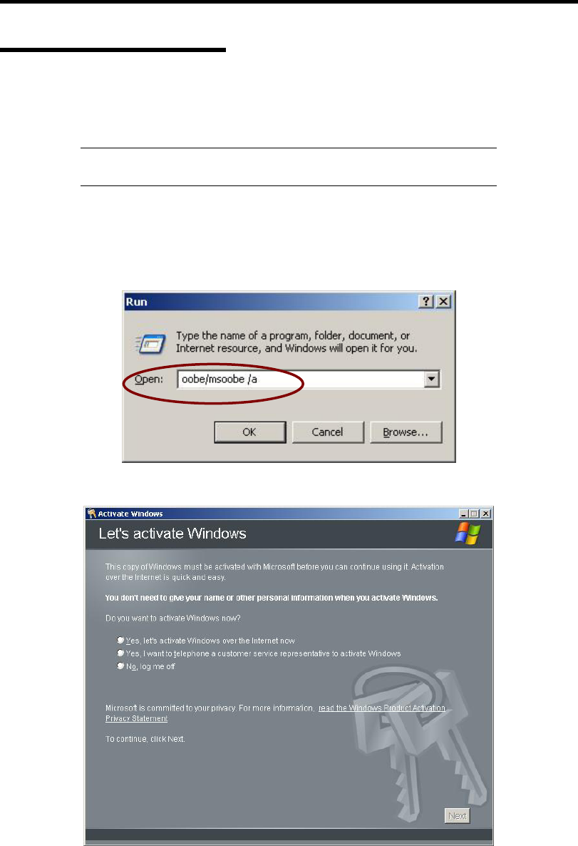
Installing Windows Server 2003 G-23
About Windows Activation
Windows Server 2003 must be activated before you can use Windows Server 2003.
Windows activation process is as follows.
NOTE: When you use Windows Server 2003 R2 Backup CD-ROM,
activation process is not needed.
1. Click [Run] on [Start] menu.
Type as follows in the [Open:] box, and click [OK].
oobe/msoobe /a
2. When the screen as follows is displayed, click [Next].
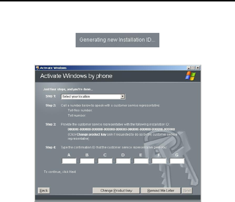
G-24 Installing Windows Server 2003
The following screen is displayed.
3. Process "Windows activation" according to the following message.
SETTING FOR SOLVING PROBLEMS
Set for collecting memory dump using the procedure described in Chapter 5.

Appendix H
Using a Client Computer Which Has a CD
Drive
The NEC EXPRESSBUILDER disk is DVD so that a client computer which you want to use for
managing the server needs a DVD drive.
If you want to install the management software of EXPRESSBUILDER to the client without the
DVD drive, make a CD-R from EXPRESSBUILDER DVD according to the following steps.
NOTE: This procedure can copy only one CD at the purpose of
installing the management software to the client.
1. Insert the EXPRESSBUILDER DVD to the computer which has a DVD drive.
2. If Autorun menu appears, close the menu.
3. Copy the below files of EXPRESSBUILDER to a hard disk by using Explorer.
\(root folder) : copy version.xml
\015
\ar_menu : copy this sub-folder
\doc : copy this sub-folder
\win : copy this sub-folder
4. Delete the ar_menu\autorun_menu.xml on the hard disk, and rename the
ar_menu\autorun_en.xml on the hard disk to the autorun_menu.xml.
5. Copy the above files/folders to a CD-R.
Match the root folder when you burn a CD-R.
6. Delete the files/folders that you copied at step 3.
7. Insert the CD-R to a client computer which you want to install the management software.
8. Kick the below file of the CD-R by using Explorer.
\015\ar_menu\autorun_menu.exe (for Windows 32 bit edition)
autorun_menu_x64.exe (for Windows 64 bit edition)

H-2 Using a Client Computer Which Has a CD Drive
(This page is intentionally left blank.)

Appendix I
Product Configuration Record Table
Use this table for information about setup and system environment change.
Hardware
Main Unit
Model name Serial No. Date Installed
CPU
#1 Clock Serial No. Date Installed
Memory
#1 Size Serial No. Date Installed
#2 Size Serial No. Date Installed
#3 Size Serial No. Date Installed
#4 Size Serial No. Date Installed
Monitor
Type Model name Serial No.
Date Installed
Hard Disk Drive
Slot #0 Type Serial No.
Capacity Date Installed
Type number
Slot #1 Type Serial No.
Capacity Date Installed
Type number
Slot #2 Type Serial No.
Capacity Date Installed
Type number
Slot #3 Type Serial No.
Capacity Date Installed
Type number

I-2 Product Configuration Record Table
5.25-inch Device
Size Capacity Serial No. Slot 1
(factory-installe
d optical disk
drive)
Model name Type number Date Installed
Size Capacity Serial No. Slot 2
Model name Type number Date Installed
PCI Slot #1
Model name Serial No.
Date Installed
PCI Slot #2
Model name Serial No.
Date Installed
PCI Slot #3
Model name Serial No.
Date Installed
PCI Slot #4
Model name Serial No.
Date Installed
Printer
Model name Serial No.
Manufacturer Date Installed
External Peripheral Device 1
Model name Serial No.
Manufacturer Date Installed
External Peripheral Device 2
Model name Serial No.
Manufacturer Date Installed
External Peripheral Device 3
Model name Serial No.
Manufacturer Date Installed
External Peripheral Device 4
Model name Serial No.
Manufacturer Date Installed

Product Configuration Record Table I-3
Software
Firmware version
OS Name: Version:
Application of RUR media Apply Name: Version:
File system FAT HPFS NTFS
Others ( )
Bundled software installed
Licensed software installed
Application running when a failure
occurred
Remarks

I-4 Product Configuration Record Table
(This page is intentionally left blank.)
