Netgear orporated 10100129 N600 WIRELESS DUAL BAND GIGABIT VDSL2 MODEM ROUTER User Manual 1
Netgear Incorporated N600 WIRELESS DUAL BAND GIGABIT VDSL2 MODEM ROUTER Users Manual 1
Contents
- 1. Users Manual 1
- 2. Users Manual 2
Users Manual 1
350 East Plumeria Drive
San Jose, CA 95134
USA
February 2011
202-10642-01
v1.0
N600 Wireless Dual Band
Gigabit ADSL2+ Modem
Router DGND3700
User Manual

2 |
N600 Wireless Dual Band Gigabit ADSL2+ Modem Router DGND3700 User Manual
© 2011 NETGEAR, Inc. All rights reserved.
No part of this publication may be reproduced, transmitted, transcribed, stored in a retrieval system, or translated
into any language in any form or by any means without the written permission of NETGEAR, Inc.
Technical Support
Thank you for choosing NETGEAR. To register your product, get the latest product updates, or get support online,
visit us at http://support.netgear.com.
Phone (US & Canada only): 1-888-NETGEAR
Phone (Other Countries): See Support information card.
Trademarks
NETGEAR, the NETGEAR logo, ReadyNAS, ProSafe, Smart Wizard, Auto Uplink, X-RAID2, and NeoTV are
trademarks or registered trademarks of NETGEAR, Inc. Microsoft, Windows, Windows NT, and Vista are
registered trademarks of Microsoft Corporation. Other brand and product names are registered trademarks or
trademarks of their respective holders.
Statement of Conditions
To improve internal design, operational function, and/or reliability, NETGEAR reserves the right to make changes
to the products described in this document without notice. NETGEAR does not assume any liability that may occur
due to the use, or application of, the product(s) or circuit layout(s) described herein.

Contents |3
Contents
Chapter 1 Hardware Setup
Unpack Your New Router. . . . . . . . . . . . . . . . . . . . . . . . . . . . . . . . . . . . . .11
Hardware Features. . . . . . . . . . . . . . . . . . . . . . . . . . . . . . . . . . . . . . . . . . .12
Label. . . . . . . . . . . . . . . . . . . . . . . . . . . . . . . . . . . . . . . . . . . . . . . . . . . .12
Back Panel . . . . . . . . . . . . . . . . . . . . . . . . . . . . . . . . . . . . . . . . . . . . . . .13
Front Panel. . . . . . . . . . . . . . . . . . . . . . . . . . . . . . . . . . . . . . . . . . . . . . .14
Position Your Wireless Router . . . . . . . . . . . . . . . . . . . . . . . . . . . . . . . . . .17
ADSL Microfilters . . . . . . . . . . . . . . . . . . . . . . . . . . . . . . . . . . . . . . . . . . . .18
One-Line ADSL Microfilter (Not Included) . . . . . . . . . . . . . . . . . . . . . . .18
Two-Line ADSL Microfilter (Included). . . . . . . . . . . . . . . . . . . . . . . . . . .19
Summary . . . . . . . . . . . . . . . . . . . . . . . . . . . . . . . . . . . . . . . . . . . . . . . .19
Cable Your N600 Wireless Modem Router . . . . . . . . . . . . . . . . . . . . . . . .20
Verify the Cabling . . . . . . . . . . . . . . . . . . . . . . . . . . . . . . . . . . . . . . . . . . . .20
For More Information . . . . . . . . . . . . . . . . . . . . . . . . . . . . . . . . . . . . . . . . .21
Chapter 2 Router Internet Setup
Router Setup Preparation. . . . . . . . . . . . . . . . . . . . . . . . . . . . . . . . . . . . . .23
Use Standard TCP/IP Properties for DHCP . . . . . . . . . . . . . . . . . . . . . .23
Replace an Existing Router . . . . . . . . . . . . . . . . . . . . . . . . . . . . . . . . . .23
Adapters and Security Settings . . . . . . . . . . . . . . . . . . . . . . . . . . . . . . .23
Gather ISP Information. . . . . . . . . . . . . . . . . . . . . . . . . . . . . . . . . . . . . .23
Log In to the N600 Modem Router . . . . . . . . . . . . . . . . . . . . . . . . . . . . . . .24
Upgrade Router Firmware . . . . . . . . . . . . . . . . . . . . . . . . . . . . . . . . . . . . .25
Router Interface . . . . . . . . . . . . . . . . . . . . . . . . . . . . . . . . . . . . . . . . . . . . .26
Setup Wizard . . . . . . . . . . . . . . . . . . . . . . . . . . . . . . . . . . . . . . . . . . . . . . .27
ADSL Settings . . . . . . . . . . . . . . . . . . . . . . . . . . . . . . . . . . . . . . . . . . . . . .31
Unsuccessful Internet Connection . . . . . . . . . . . . . . . . . . . . . . . . . . . . . . .32
Change Password and Login Time-Out . . . . . . . . . . . . . . . . . . . . . . . . . . .32
Log Out Manually . . . . . . . . . . . . . . . . . . . . . . . . . . . . . . . . . . . . . . . . . . . .33
Types of Logins . . . . . . . . . . . . . . . . . . . . . . . . . . . . . . . . . . . . . . . . . . . . .33
Chapter 3 Wireless Settings
Wireless Security Requirements and Recommendations . . . . . . . . . . . . .36
Wireless Security Basics . . . . . . . . . . . . . . . . . . . . . . . . . . . . . . . . . . . . . .36
Turn Off Wireless Connectivity . . . . . . . . . . . . . . . . . . . . . . . . . . . . . . . .37
Disable SSID Broadcast. . . . . . . . . . . . . . . . . . . . . . . . . . . . . . . . . . . . .37
Restrict Access by MAC Address. . . . . . . . . . . . . . . . . . . . . . . . . . . . . .37
Wireless Security Options . . . . . . . . . . . . . . . . . . . . . . . . . . . . . . . . . . .37
Add Clients (Devices) to Your Network . . . . . . . . . . . . . . . . . . . . . . . . . . .39

4| Contents
N600 Wireless Dual Band Gigabit ADSL2+ Modem Router DGND3700 User Manual
Manual Method. . . . . . . . . . . . . . . . . . . . . . . . . . . . . . . . . . . . . . . . . . . . 39
Wi-Fi Protected Setup (WPS) Method . . . . . . . . . . . . . . . . . . . . . . . . . . 39
Wireless Settings Screen . . . . . . . . . . . . . . . . . . . . . . . . . . . . . . . . . . . . . .41
Consider Every Device on Your Network . . . . . . . . . . . . . . . . . . . . . . . .41
Configure Wireless Settings . . . . . . . . . . . . . . . . . . . . . . . . . . . . . . . . . . 42
Chapter 4 Security Settings
Keyword Blocking of HTTP Traffic . . . . . . . . . . . . . . . . . . . . . . . . . . . . . . .48
Delete Keyword or Domain. . . . . . . . . . . . . . . . . . . . . . . . . . . . . . . . . . . 48
Specify Trusted Computer . . . . . . . . . . . . . . . . . . . . . . . . . . . . . . . . . . . 48
Firewall Rules to Control Network Access . . . . . . . . . . . . . . . . . . . . . . . . .49
Remote Computer Access Basics . . . . . . . . . . . . . . . . . . . . . . . . . . . . .49
Port Triggering to Open Incoming Ports. . . . . . . . . . . . . . . . . . . . . . . . .50
Port Forwarding to Permit External Host Communications . . . . . . . . . .51
How Port Forwarding Differs from Port Triggering . . . . . . . . . . . . . . . . .52
Configure Port Forwarding to Local Servers . . . . . . . . . . . . . . . . . . . . .53
Configure Port Triggering . . . . . . . . . . . . . . . . . . . . . . . . . . . . . . . . . . . .55
Configure Services. . . . . . . . . . . . . . . . . . . . . . . . . . . . . . . . . . . . . . . . . . . 57
Set the Time Zone . . . . . . . . . . . . . . . . . . . . . . . . . . . . . . . . . . . . . . . . . . . 58
Schedule Firewall Services . . . . . . . . . . . . . . . . . . . . . . . . . . . . . . . . . . . .59
Enable Security Event Email Notification . . . . . . . . . . . . . . . . . . . . . . . . . .59
Log the Network Activity. . . . . . . . . . . . . . . . . . . . . . . . . . . . . . . . . . . . . . . 61
Chapter 5 Network Maintenance
Upgrade the Router Firmware . . . . . . . . . . . . . . . . . . . . . . . . . . . . . . . . . .64
Automatic Firmware Checking Off . . . . . . . . . . . . . . . . . . . . . . . . . . . . . 64
Automatic Firmware Checking On . . . . . . . . . . . . . . . . . . . . . . . . . . . . . 64
Manually Check for Firmware Upgrades . . . . . . . . . . . . . . . . . . . . . . . . . .65
Manage Configuration File . . . . . . . . . . . . . . . . . . . . . . . . . . . . . . . . . . . . . 66
Back Up . . . . . . . . . . . . . . . . . . . . . . . . . . . . . . . . . . . . . . . . . . . . . . . . .66
Restore. . . . . . . . . . . . . . . . . . . . . . . . . . . . . . . . . . . . . . . . . . . . . . . . . .66
Erase . . . . . . . . . . . . . . . . . . . . . . . . . . . . . . . . . . . . . . . . . . . . . . . . . . . 66
View Router Status. . . . . . . . . . . . . . . . . . . . . . . . . . . . . . . . . . . . . . . . . . .67
Show Statistics Button . . . . . . . . . . . . . . . . . . . . . . . . . . . . . . . . . . . . . . 69
Connection Status Button. . . . . . . . . . . . . . . . . . . . . . . . . . . . . . . . . . . . 70
View Attached Devices. . . . . . . . . . . . . . . . . . . . . . . . . . . . . . . . . . . . . . . .71
Run Diagnostic Utilities . . . . . . . . . . . . . . . . . . . . . . . . . . . . . . . . . . . . . . .71
Chapter 6 USB Storage
USB Drive Requirements . . . . . . . . . . . . . . . . . . . . . . . . . . . . . . . . . . . . . .73
File-Sharing Scenarios. . . . . . . . . . . . . . . . . . . . . . . . . . . . . . . . . . . . . . . . 73
Sharing Photos with Friends and Family . . . . . . . . . . . . . . . . . . . . . . . .74
Storing Files in a Central Location for Printing . . . . . . . . . . . . . . . . . . . .74
Sharing Large Files with Colleagues . . . . . . . . . . . . . . . . . . . . . . . . . . .75
USB Storage Basic Settings. . . . . . . . . . . . . . . . . . . . . . . . . . . . . . . . . . . .75
Editing a Network Folder . . . . . . . . . . . . . . . . . . . . . . . . . . . . . . . . . . . . . . 77

Contents | 5
N600 Wireless Dual Band Gigabit ADSL2+ Modem Router DGND3700 User Manual
Configuring USB Storage Advanced Settings . . . . . . . . . . . . . . . . . . . . . .78
Creating a Network Folder . . . . . . . . . . . . . . . . . . . . . . . . . . . . . . . . . . .79
Unmounting a USB Drive . . . . . . . . . . . . . . . . . . . . . . . . . . . . . . . . . . . . . .80
Specifying Approved USB Devices . . . . . . . . . . . . . . . . . . . . . . . . . . . . . .80
Connecting to the USB Drive from a Remote Computer . . . . . . . . . . . . . .81
Locating the Internet Port IP Address. . . . . . . . . . . . . . . . . . . . . . . . . . .81
Accessing the Router’s USB Drive Remotely Using FTP. . . . . . . . . . . .81
Connecting to the USB Drive with Microsoft Network Settings . . . . . . . . .81
Enabling File and Printer Sharing. . . . . . . . . . . . . . . . . . . . . . . . . . . . . .82
Setting Up a Media Server . . . . . . . . . . . . . . . . . . . . . . . . . . . . . . . . . . . . .82
Chapter 7 Virtual Private Networking
Overview of VPN Configuration . . . . . . . . . . . . . . . . . . . . . . . . . . . . . . . . .85
Client-to-Gateway VPN Tunnels. . . . . . . . . . . . . . . . . . . . . . . . . . . . . . .85
Gateway-to-Gateway VPN Tunnels . . . . . . . . . . . . . . . . . . . . . . . . . . . .86
Planning a VPN . . . . . . . . . . . . . . . . . . . . . . . . . . . . . . . . . . . . . . . . . . . . .86
VPN Tunnel Configuration . . . . . . . . . . . . . . . . . . . . . . . . . . . . . . . . . . . . .88
Setting Up a Client-to-Gateway VPN Configuration . . . . . . . . . . . . . . . . . .88
Step 1: Configure the Client-to-Gateway VPN Tunnel . . . . . . . . . . . . . .89
Step 2: Configure the NETGEAR ProSafe VPN Client. . . . . . . . . . . . . .92
Setting Up a Gateway-to-Gateway VPN Configuration . . . . . . . . . . . . . . .99
VPN Tunnel Control . . . . . . . . . . . . . . . . . . . . . . . . . . . . . . . . . . . . . . . . .103
Activating a VPN Tunnel. . . . . . . . . . . . . . . . . . . . . . . . . . . . . . . . . . . .103
Verifying the Status of a VPN Tunnel . . . . . . . . . . . . . . . . . . . . . . . . . .106
Deactivating a VPN Tunnel. . . . . . . . . . . . . . . . . . . . . . . . . . . . . . . . . .107
Deleting a VPN Tunnel . . . . . . . . . . . . . . . . . . . . . . . . . . . . . . . . . . . . .109
Setting Up VPN Tunnels in Special Circumstances . . . . . . . . . . . . . . . . .109
Using Auto Policy to Configure VPN Tunnels. . . . . . . . . . . . . . . . . . . .110
Using Manual Policy to Configure VPN Tunnels . . . . . . . . . . . . . . . . .117
Chapter 8 Advanced Settings
WAN Setup. . . . . . . . . . . . . . . . . . . . . . . . . . . . . . . . . . . . . . . . . . . . . . . .121
WAN Preference. . . . . . . . . . . . . . . . . . . . . . . . . . . . . . . . . . . . . . . . . .121
Disable Port Scan and DOS Protection . . . . . . . . . . . . . . . . . . . . . . . .121
Default DMZ Server . . . . . . . . . . . . . . . . . . . . . . . . . . . . . . . . . . . . . . .121
Respond To Ping On Internet Port . . . . . . . . . . . . . . . . . . . . . . . . . . . .122
MTU Size (in bytes) . . . . . . . . . . . . . . . . . . . . . . . . . . . . . . . . . . . . . . .122
NAT Filtering. . . . . . . . . . . . . . . . . . . . . . . . . . . . . . . . . . . . . . . . . . . . .122
Disable SIP ALG. . . . . . . . . . . . . . . . . . . . . . . . . . . . . . . . . . . . . . . . . .123
Dynamic DNS. . . . . . . . . . . . . . . . . . . . . . . . . . . . . . . . . . . . . . . . . . . . . .123
LAN Setup . . . . . . . . . . . . . . . . . . . . . . . . . . . . . . . . . . . . . . . . . . . . . . . .124
Device Name . . . . . . . . . . . . . . . . . . . . . . . . . . . . . . . . . . . . . . . . . . . .125
Use Auto IP. . . . . . . . . . . . . . . . . . . . . . . . . . . . . . . . . . . . . . . . . . . . . .125
IP Address . . . . . . . . . . . . . . . . . . . . . . . . . . . . . . . . . . . . . . . . . . . . . .125
IP Subnet Mask . . . . . . . . . . . . . . . . . . . . . . . . . . . . . . . . . . . . . . . . . .125
Use Router as DHCP Server . . . . . . . . . . . . . . . . . . . . . . . . . . . . . . . .125
Reserved IP Addresses Setup . . . . . . . . . . . . . . . . . . . . . . . . . . . . . . .125

6| Contents
N600 Wireless Dual Band Gigabit ADSL2+ Modem Router DGND3700 User Manual
Setting Up Quality of Service (QoS). . . . . . . . . . . . . . . . . . . . . . . . . . . . .126
Configuring QoS for Internet Access . . . . . . . . . . . . . . . . . . . . . . . . . .127
Advanced Wireless Settings. . . . . . . . . . . . . . . . . . . . . . . . . . . . . . . . . . .128
Wireless Advanced Settings. . . . . . . . . . . . . . . . . . . . . . . . . . . . . . . . . 129
WPS Settings . . . . . . . . . . . . . . . . . . . . . . . . . . . . . . . . . . . . . . . . . . . . 129
Building Wireless Bridging and Repeating Networks . . . . . . . . . . . . . . . .130
Point-to-Point Bridge Configuration . . . . . . . . . . . . . . . . . . . . . . . . . . .131
Multi-Point Bridge . . . . . . . . . . . . . . . . . . . . . . . . . . . . . . . . . . . . . . . . . 132
Repeater with Wireless Client Association. . . . . . . . . . . . . . . . . . . . . .134
Remote Management. . . . . . . . . . . . . . . . . . . . . . . . . . . . . . . . . . . . . . . .135
Static Routes . . . . . . . . . . . . . . . . . . . . . . . . . . . . . . . . . . . . . . . . . . . . . . 137
Static Route Example. . . . . . . . . . . . . . . . . . . . . . . . . . . . . . . . . . . . . .137
Configure Static Routes . . . . . . . . . . . . . . . . . . . . . . . . . . . . . . . . . . . . 138
Universal Plug and Play . . . . . . . . . . . . . . . . . . . . . . . . . . . . . . . . . . . . . . 139
Advanced USB Settings. . . . . . . . . . . . . . . . . . . . . . . . . . . . . . . . . . . . . . 140
Traffic Meter . . . . . . . . . . . . . . . . . . . . . . . . . . . . . . . . . . . . . . . . . . . . . . .141
Chapter 9 Troubleshooting
Router Not On . . . . . . . . . . . . . . . . . . . . . . . . . . . . . . . . . . . . . . . . . . . . . 144
Power LED Is Off . . . . . . . . . . . . . . . . . . . . . . . . . . . . . . . . . . . . . . . . . 144
Power LED Is Red . . . . . . . . . . . . . . . . . . . . . . . . . . . . . . . . . . . . . . . .145
LAN LED Is Off. . . . . . . . . . . . . . . . . . . . . . . . . . . . . . . . . . . . . . . . . . .145
Wireless LEDs Are Off . . . . . . . . . . . . . . . . . . . . . . . . . . . . . . . . . . . . . 145
DSL or Internet LED Is Off . . . . . . . . . . . . . . . . . . . . . . . . . . . . . . . . . . 145
No ISP Connection. . . . . . . . . . . . . . . . . . . . . . . . . . . . . . . . . . . . . . . . . .146
ADSL Link. . . . . . . . . . . . . . . . . . . . . . . . . . . . . . . . . . . . . . . . . . . . . . . 146
Internet LED Is Red . . . . . . . . . . . . . . . . . . . . . . . . . . . . . . . . . . . . . . .147
Cannot Obtain an Internet IP Address . . . . . . . . . . . . . . . . . . . . . . . . . 147
Debug PPPoE or PPPoA . . . . . . . . . . . . . . . . . . . . . . . . . . . . . . . . . . . 148
Cannot Load an Internet Web Page. . . . . . . . . . . . . . . . . . . . . . . . . . .148
TCP/IP Network Not Responding. . . . . . . . . . . . . . . . . . . . . . . . . . . . . . .148
Test the LAN Path to Your Wireless Modem Router . . . . . . . . . . . . . .149
Test the Path from Your Computer to a Remote Device . . . . . . . . . . .150
Cannot Log in. . . . . . . . . . . . . . . . . . . . . . . . . . . . . . . . . . . . . . . . . . . . . . 150
Changes Not Saved . . . . . . . . . . . . . . . . . . . . . . . . . . . . . . . . . . . . . . . . . 151
Firmware Needs to Be Reloaded . . . . . . . . . . . . . . . . . . . . . . . . . . . . . . .151
Incorrect Date or Time . . . . . . . . . . . . . . . . . . . . . . . . . . . . . . . . . . . . . . . 152
Appendix A Supplemental Information
Factory Settings . . . . . . . . . . . . . . . . . . . . . . . . . . . . . . . . . . . . . . . . . . . .154
Technical Specifications. . . . . . . . . . . . . . . . . . . . . . . . . . . . . . . . . . . . . .156
Appendix B NETGEAR VPN Configuration
Configuration Profile. . . . . . . . . . . . . . . . . . . . . . . . . . . . . . . . . . . . . . . . .157
Step-by-Step Configuration . . . . . . . . . . . . . . . . . . . . . . . . . . . . . . . . .158
Wireless Modem Router with FQDN to Gateway B . . . . . . . . . . . . . . . . . 160

Contents | 7
N600 Wireless Dual Band Gigabit ADSL2+ Modem Router DGND3700 User Manual
Configuration Profile . . . . . . . . . . . . . . . . . . . . . . . . . . . . . . . . . . . . . . .160
Step-by-Step Configuration . . . . . . . . . . . . . . . . . . . . . . . . . . . . . . . . .161
Configuration Summary (Telecommuter Example) . . . . . . . . . . . . . . . . .164
Setting Up Client-to-Gateway VPN (Telecommuter Example) . . . . . . . . .165
Step 1: Configure Gateway A (VPN Router at Main Office) . . . . . . . . .166
Step 2: Configure Gateway B (VPN Router at Regional Office). . . . . .167
Monitoring the VPN Tunnel (Telecommuter Example) . . . . . . . . . . . . . . .173
Viewing the VPN Router’s VPN Status and Log Information . . . . . . . .174
Appendix C Notification of Compliance
Index
FederalCommunicationCommissionInterferenceStatement
ThisequipmenthasbeentestedandfoundtocomplywiththelimitsforaClassBdigitaldevice,pursuant
toPart15oftheFCCRules.Theselimitsaredesignedtoprovidereasonableprotectionagainstharmful
interferenceinaresidentialinstallation.Thisequipmentgenerates,usesandcanradiateradiofrequency
energyand,ifnotinstalledandusedinaccordancewiththeinstructions,maycauseharmfulinterferenceto
radiocommunications.However,thereisnoguaranteethatinterferencewillnotoccurinaparticular
installation.Ifthisequipmentdoescauseharmfulinterferencetoradioortelevisionreception,whichcanbe
determinedbyturningtheequipmentoffandon,theuserisencouragedtotrytocorrecttheinterferenceby
oneofthefollowingmeasures:
●Reorientorrelocatethereceivingantenna.
●Increasetheseparaonbetweentheequipmentandreceiver.
●Connecttheequipmentintoanoutletonacircuitdifferentfromthattowhichthereceiverisconnected.
●Consultthedealeroranexperiencedradio/TVtechnicianforhelp.
FCCCaution:Anychangesormodificationsnotexpresslyapprovedbythepartyresponsiblefor
compliancecouldvoidtheuser’sauthoritytooperatethisequipment.
ThisdevicecomplieswithPart15oftheFCCRules.Operationissubjecttothefollowingtwoconditions:(1)
Thisdevicemaynotcauseharmfulinterference,and(2)thisdevicemustacceptanyinterferencereceived,
includinginterferencethatmaycauseundesiredoperation.
ForproductavailableintheUSA/Canadamarket,onlychannel1~11canbeoperated.Selectionofother
channelsisnotpossible.
Thisdeviceisgoingtobeoperatedin5.15~5.25GHzfrequencyrange,itisrestrictedinindoorenvironment
only.
Deviceswillnotpermitoperationsonchannels120‐132for11aand11n/awhichoverlapthe5600‐5650
MHzband.
InordertomeetnewFCC,NTIA,FAAandindustryrestrictionstoresolveinterferencetoTerminalDoppler
WeatherRadar(TDWR)systemsusedatairports,anyoutdoordeviceinstalledwithin35kmofaTDWRlocation
mustbeseparatedbyatleast30MHz(center‐to‐center)fromTDWRoperatingfrequency(asshowninthe
tablebelow).Channels120‐132and5600‐5650MHzbandaredisabledonoutdoorproducts.
WerecommendthatalloperatorsandinstallersregisterthelocationinformationoftheUNIIdevices
operatingoutdoorsinthe5470–5725MHzbandwithin35kmofanyTDWRlocationattheWISPAsponsored
database(seehttp://www.spectrumbridge.com/udia/home.aspx).Thisdatabasemaybeusedbygovernment
agenciesinordertoexpediteresolutionofanyinterferencetoTDWRs.
Proceduresonhowtoregisterthedevicesintheindustry‐sponsoreddatabasewiththeappropriate
informationregardingthelocationandoperationofthedeviceandinstallerinformationcanbefoundonthe
database.
IMPORTANTNOTE:
FCCRadiationExposureStatement:
ThisequipmentcomplieswithFCCradiationexposurelimitssetforthforanuncontrolledenvironment.
Thisequipmentshouldbeinstalledandoperatedwithminimumdistance20cmbetweentheradiator&your
body.

CEStatement:
Hereby,NetgearInc.,declaresthatthisdeviceisincompliancewiththeessential
requirementsandotherrelevantprovisionsoftheR&TTEDirective1999/5/EC.
ThisdevicewillbesoldinthefollowingEEAcountries:Austria,Italy,Belgium,Liechtenstein,Denmark,
Luxembourg,Finland,Netherlands,France,Norway,Germany,Portugal,Greece,Spain,Iceland,Sweden,Ireland,
UnitedKingdom,Cyprus,CzechRepublic,Estonia,Hungary,Latvia,Lithuania,Malta,Slovakia,Poland,Slovenia.

Chapter 1. Hardware Setup | 8
1
1. Hardware Setup
Getting to know your wireless router
The NETGEAR N600 Wireless Dual Band Gigabit ADSL2+ Modem Router DGND3700 is the
Ultimate Integrated ADSL Networking Gateway. It offers concurrent dual band technology which
avoids interference and ensures top speeds and the greatest range for demanding applications,
such as streaming HD video and multiplayer gaming. Complete with a built-in ADSL modem, it is
compatible with all major ADSL Internet service providers. The Gigabit port on the WAN side
also as an option to connect to a Fiber/Cable modem.
•All-in-one. Built-in ADSL2+ modem and WAN Gigabit Ethernet port for cable/fiber
combined with a wireless router create the Ultimate Integrated Home Gateway.
•Concurrent dual band. Eusuring top speeds and the greatest range while minimizing
interference.
•Faster multimedia streaming. Provides Wireless-N speed for streaming HD videos,
simultaneous downloads, and online gaming in addition to basic Internet applications.
•Shared storage. Two (2) ports for ReadySHARE® USB Storage Access provides fast
and easy shared access to an external USB storage device.
•Live Parental Controls. Keeps your Internet experience safe.
•Guest network access. Provides separate security and access restrictions for guests
using the network.
•Secured connection. Push ‘N’ Connect ensures a quick and secure network
connection.
•Broadband usage meter. Monitors Internet traffic and sends customized reports to help
keep costs under control.
•Easy installation. Connect to PC and open your browser to install.
•Compatibility. Compatible with all major ADSL Internet service providers (ISPs).
•Broadband usage meter. Monitors Internet traffic and sends customized reports to help
keep costs under control.
Product specifications
Package Contents
•N600 Wireless Dual Band Gigabit ADSL2+ Modem Router DGND3700
•Ethernet cable
•Phone cable and filter

Chapter 1. Hardware Setup | 9
N600 Wireless Dual Band Gigabit ADSL2+ Modem Router DGND3700 User Manual
•Power adapter, localized to country of sale
Warranty
•NETGEAR 1-year warranty
System Requirements
•Broadband Internet service
-ADSL Broadband Internet Service
-Cable or Fiber: Connects to cable modem via Gigabit Ethernet WAN port
•802.11 a/b/g/n 2.4 or 5.0 GHz specification wireless adapter or an Ethernet adapter and
cable for each computer
•Microsoft® Windows 7®, Vista®, XP®, 2000, Me®, Mac OS®, UNIX®, or Linux®
•Microsoft® Internet Explorer® 5.0, Firefox® 2.0 or Safari 1.4 or higher
•Use with an N600 Wireless Dual Band USB Adapter (WNDA3100 for maximum
performance)
Standards
•IEEE 802.11 b/g/n 2.4 GHz
•IEEE 802.11 a/n 5.0 GHz
•Five (5) 10/100/1000 (1 WAN and 4 LAN) Gigabit Ethernet ports
•Two (2) USB 2.0 ports
•One (1) ADSL2+ port
Performance
•All-in-one. High Speed ADSL2+ Modem (built-in) and WAN Gigabit Ethernet port for
cable/fiber
•Powerful Dual Core (400 MHz each) processor
•High speed access to external USB storage using 2 USB 2.0 ports
•Memory: 128 MB Flash and 128 MB RAM
•Five (5) (1 WAN, 4 LAN) Gigabit Ethernet ports
•Advanced Quality of Service (QoS)
Security
•Wi-Fi Protected Access® (WPA/WPA2—PSK) and WEP
•Double firewall protection (SPI and NAT firewall)
•Denial-of-service (DoS) attack prevention
Ease of Use
•Easy installation. connect to PC and open your browser to install
•Push ‘N’ Connect using Wi-Fi Protected Setup® (WPS)1
Physical Specifications

10 | Chapter 1. Hardware Setup
N600 Wireless Dual Band Gigabit ADSL2+ Modem Router DGND3700 User Manual
•Dimensions: 223 x 153 x 31 mm (8.8 x 6.0 x 1.2 in)
•Weight: 0.5 kg (1.2 lb)
Advanced Features
•Live Parental Controls with flexible and customizable filter settings
•Simultaneous Dual Band. 2.4 GHz and 5 GHz operation
•Two (2) ports for ReadySHARE® USB Storage Access. supports FAT16/32, NTFS
Read/Write
•DLNA®. stream media to DLNA media players
•Multiple SSID guest networks (separate security and access restrictions)
•Broadband usage meter measures Internet usage
•Power and Wi-Fi on/off buttons
NETGEAR Green Features
Power On/Off Button
80% Recycled Packaging
CEC (California Efficiency)
RoHS
WEEE
If you have not already set up your new router using the installation guide that comes in the box,
this chapter walks you through the hardware setup. Chapter 2, Router Internet Setup, explains
how to set up your Internet connection.
This chapter contains the following sections:
•Unpack Your New Router
•Hardware Features
•Position Your Wireless Router
•ADSL Microfilters
•Cable Your N600 Wireless Modem Router
•Verify the Cabling
•For More Information
Chapter 1. Hardware Setup | 11
N600 Wireless Dual Band Gigabit ADSL2+ Modem Router DGND3700 User Manual
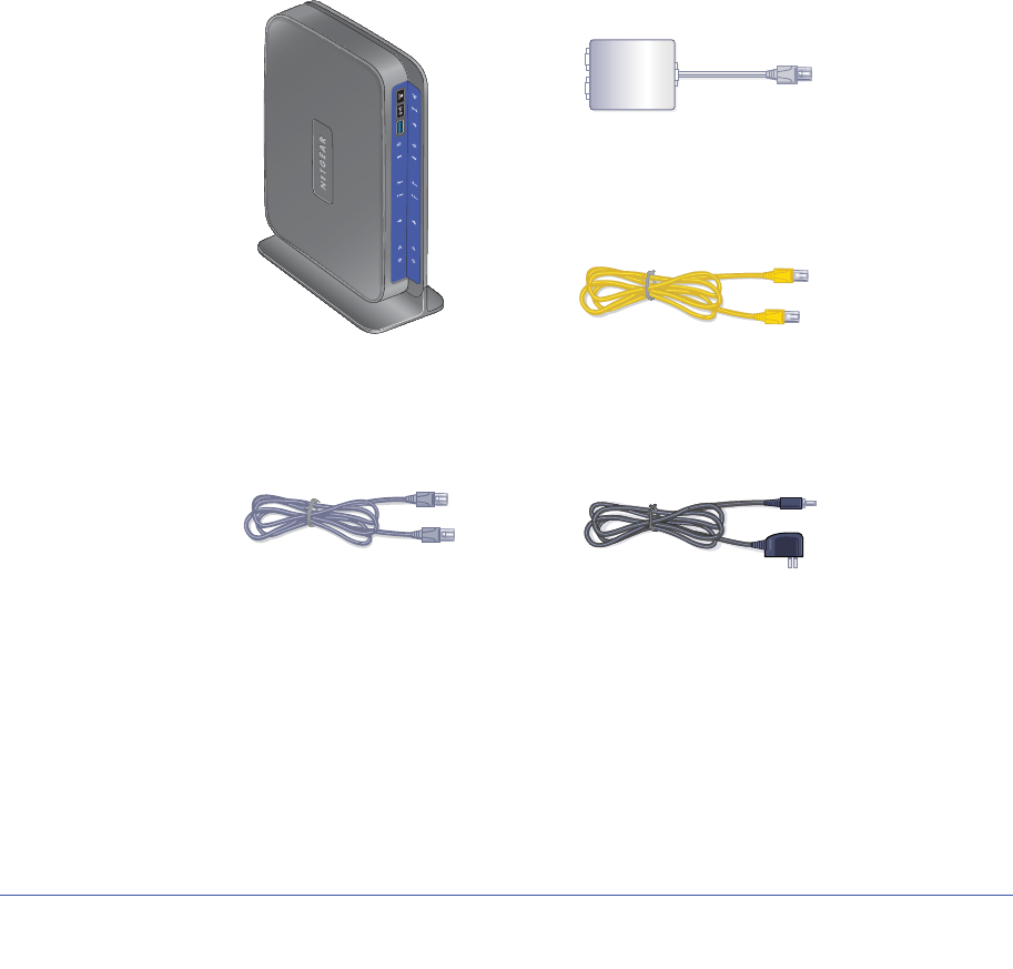
Unpack Your New Router
Your box should contain the following items:
•N600 Wireless Dual Band Gigabit ADSL2+ Modem Router DGND3700
•AC power adapter (plug varies by region)
•Category 5 (Cat 5) Ethernet cable
•Telephone cable with RJ-11 connector
•Microfilters and splitters (quantity and type vary by region)
•Installation guide with cabling and router setup instructions
If any of the parts are incorrect, missing, or damaged, contact your NETGEAR dealer. Keep
the carton, including the original packing materials, in case you need to return the product for
repair. See Position Your Wireless Router on page 17 for information about where to place
and how to position your router.
N600 Wireless Modem Router
Phone cable Power adapter
ADSL filter
ADSL
Phone
Line
Ethernet cable
Figure 1. Box contents
12 | Chapter 1. Hardware Setup
N600 Wireless Dual Band Gigabit ADSL2+ Modem Router DGND3700 User Manual
Hardware Features
Before you cable your router, take a moment to become familiar with the label and the front
and back panels. Pay particular attention to the LEDs on the front panel.
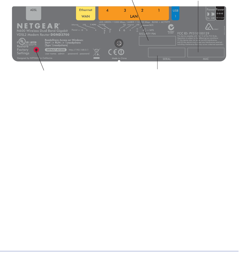
Label
The label on the bottom of the wireless modem router shows the router’s factory reset button,
WPS security PIN, MAC address, and serial number.
MAC address
Serial number
Restore Factory Settings
WPS Security PIN
Figure 2. Label on router bottom
See Factory Settings on page 154 for information about the Reset Factory Settings button
and the factory setting values.
Chapter 1. Hardware Setup | 13
N600 Wireless Dual Band Gigabit ADSL2+ Modem Router DGND3700 User Manual
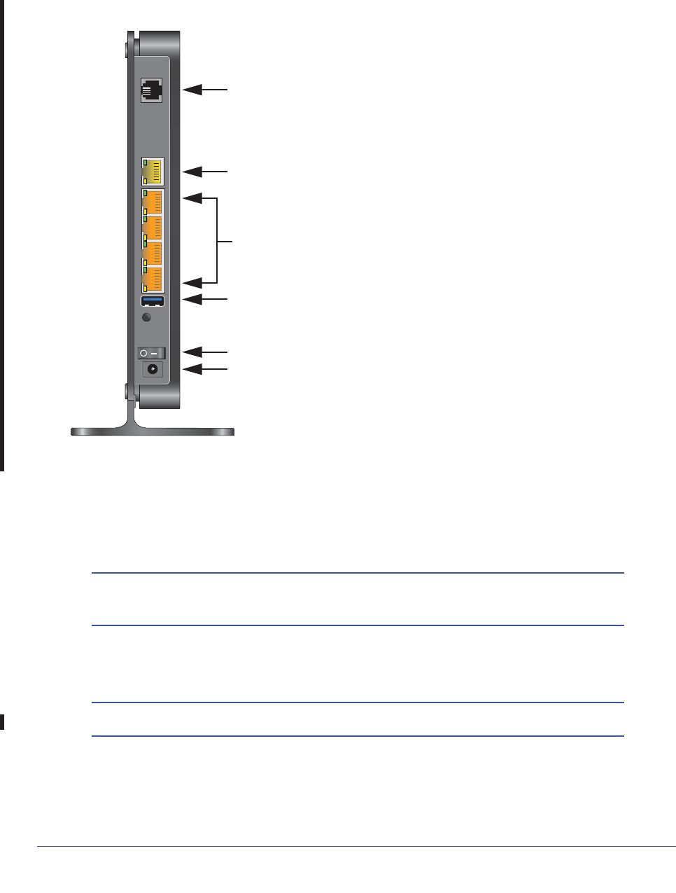
Back Panel
The back panel has the On/Off button and port connections as shown in the figure.
2. Gigabit port for connecting to external Cable/Fiber Modem
5. Power On/Off button
4. USB port
6. AC power adapter input
1. ADSL Line
3. Gigabit Ethernet ports
Figure 3. Back panel port connections
Viewed from left to right, the rear panel contains the following elements:
1. RJ-11 Asynchronous DSL (ADSL) port for connecting the wireless modem router to an
ADSL line
Note: An ADSL port is capable of sending data over an ADSL line at one
speed and receiving it at another speed.
2. Ethernet WAN port for connecting the wireless modem router to a Fiber/Cable modem
Note: You can use either the ADSL or Gigabit port for WAN connectivity.
3. Four Ethernet RJ-45 LAN ports for cabling the wireless modem router to the local computers
4. USB port for connecting USB storage devices like flash drives or hard drives
14 | Chapter 1. Hardware Setup
N600 Wireless Dual Band Gigabit ADSL2+ Modem Router DGND3700 User Manual
5. Power On/Off button
6. AC power adapter input
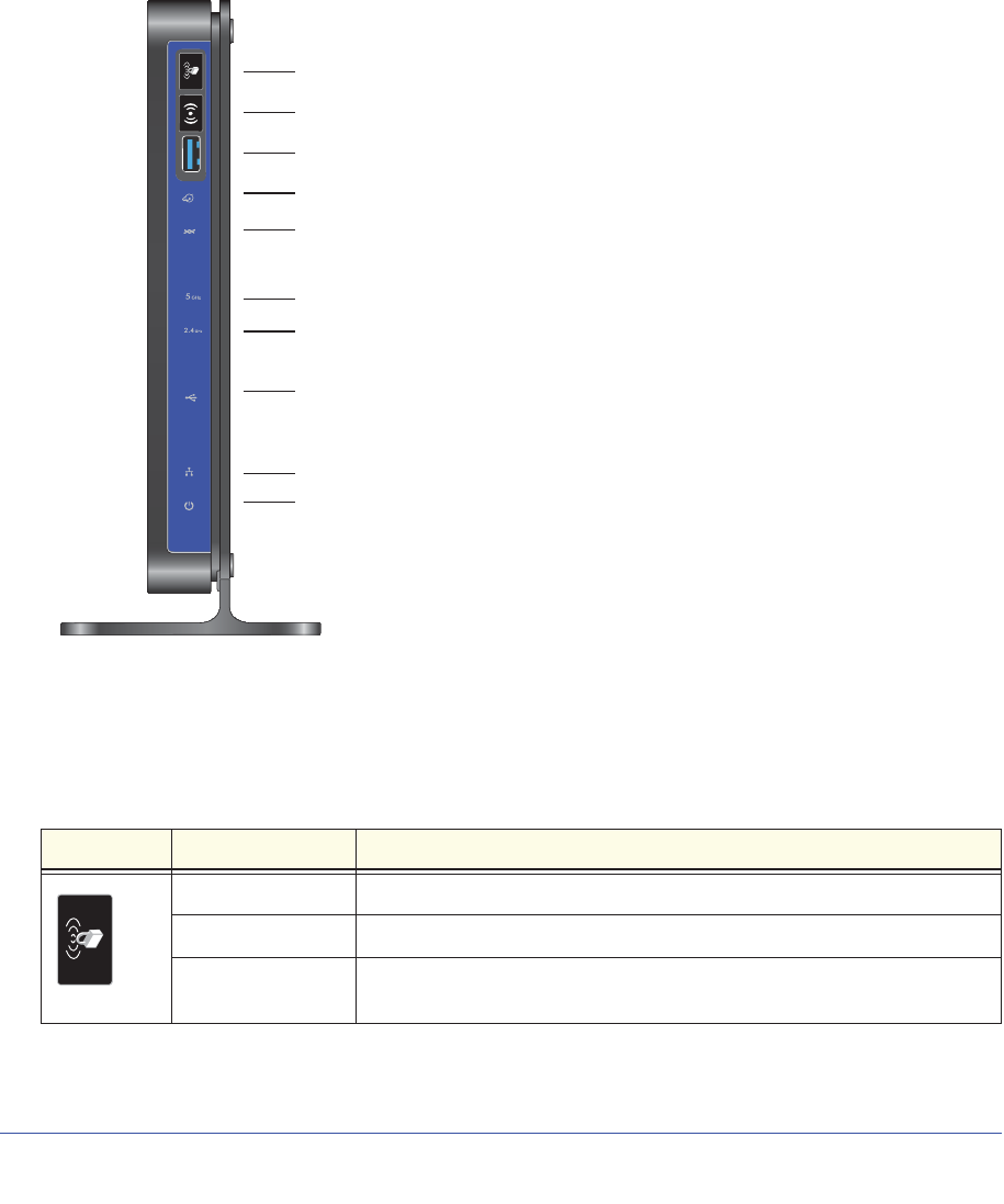
Front Panel
The wireless modem router front panel has the ten status LEDs, icons, and ports shown in
the figure. Note that the Wireless and WPS icons are buttons.
Power
LAN ports
DSL
Internet
5 GHZ Wireless
USB port
Wireless On/Off button
WPS On/Off button
2.4 GHz Wireless
USB
Figure 4. Front panel LEDs
The tables below describe the LEDs, icons, and buttons on the front panel from top to bottom.
Table 1. WPS Button and LED
Icon LED Activity Description
Solid green Indicates that wireless security has been enabled.
Blinking green WPS-capable device is connecting to the device.
Off WPS is not enabled. See Wi-Fi Protected Setup (WPS) Method on page 39
for more information about the use of this button.
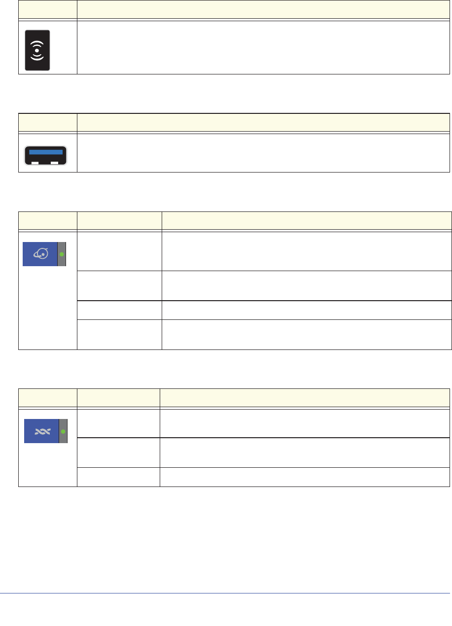
Table 2. Wireless Button
Icon Description
See Turn Off Wireless Connectivity on page 37 for more information about the use of this button.
Table 3. USB Port
Icon Description
USB port for connecting USB storage devices like flash drives or hard drives.
Table 4. Internet LED
Icon LED Activity Description
Solid green You have an Internet connection. If this connection is dropped due to an
idle time-out but the connection is still present, the light stays green. If the
Internet connection is dropped for any other reason, the light turns off.
Solid red The Internet (IP) connection failed. See No ISP Connection on page 146
for troubleshooting information.
Blinking green Data is being transmitted over the Internet connection.
Off No Internet connection is detected or the device is in bridge mode (an
external device handles the ISP connection).
Table 5. DSL LED
Icon LED Activity Description
Solid green You have an ADSL connection. In technical terms, the ADSL port is
synchronized with an ISP’s network-access device.
Blinking green Indicates that the wireless modem router is negotiating the best possible
speed on the ADSL line.
Off The unit is off or there is no IP connection.
Chapter 1. Hardware Setup | 15
N600 Wireless Dual Band Gigabit ADSL2+ Modem Router DGND3700 User Manual
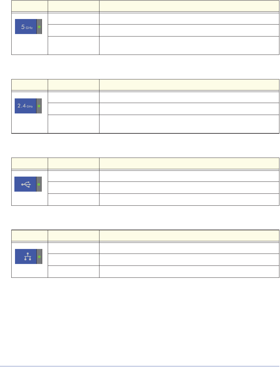
Table 6. 5 GHz Wireless LED
Icon LED Activity Description
Solid blue There is wireless connectivity.
Blinking blue Data is being transmitted or received over the 5 GHz wireless link.
Off There is no wireless connectivity. You can still plug an Ethernet cable into
one of the LAN ports to get wired connectivity.
Table 7. 2.4 GHz Wireless LED
Icon LED Activity Description
Solid green There is wireless connectivity.
Blinking green Data is being transmitted or received over the 2.4 GHz wireless link.
Off There is no wireless connectivity. You can still plug an Ethernet cable into
one of the LAN ports to get wired connectivity.
Table 8. USB LED
Icon LED Activity Description
Solid green A USB port has detected a USB device.
Blinking green Data is being transmitted or received.
Off No link is detected on these ports.
Table 9. LAN LED
Icon LED Activity Description
Solid green A LAN port has detected an Ethernet link with a device.
Blinking green Data is being transmitted or received.
Off No link is detected on these ports.
16 | Chapter 1. Hardware Setup
N600 Wireless Dual Band Gigabit ADSL2+ Modem Router DGND3700 User Manual
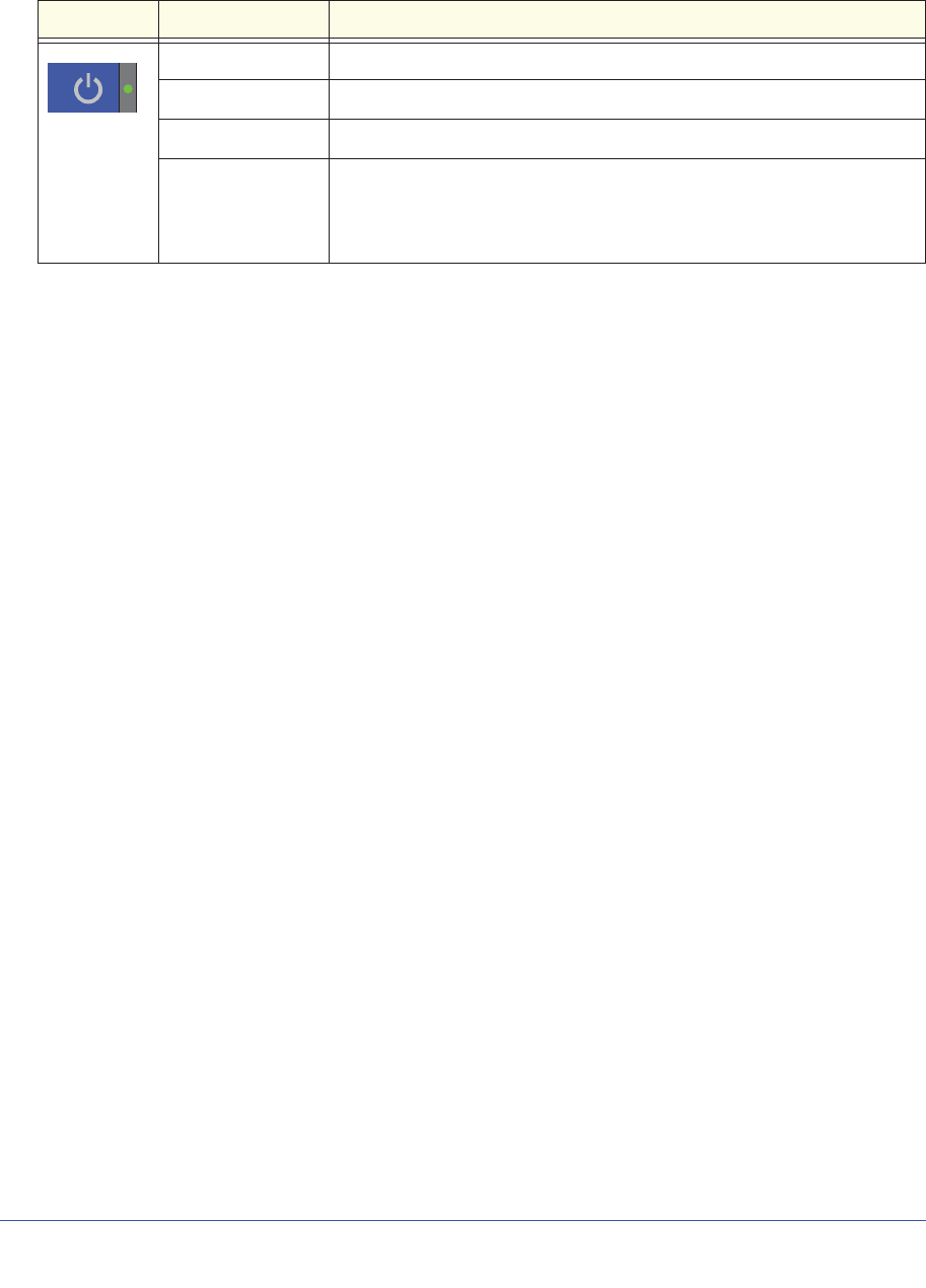
Table 10. Power On/Off button
Icon LED Activity Description
Solid green Power is supplied to the router.
Solid red POST (power-on self-test) failure or a device malfunction has occurred.
Off Power is not supplied to the router.
Restore factory
settings Light blinks momentarily when the Restore Factory Settings button on the
bottom of the unit is pressed for 6 seconds. The Power LED then blinks red
three times when the Restore Factory Settings button is released and then
turns green as the gateway resets to the factory defaults.
Chapter 1. Hardware Setup | 17
N600 Wireless Dual Band Gigabit ADSL2+ Modem Router DGND3700 User Manual
Position Your Wireless Router
The wireless modem router lets you access your network from virtually anywhere within the
operating range of your wireless network. However, the operating distance or range of your
wireless connection can vary significantly depending on the physical placement of your
router. For example, the thickness and number of walls the wireless signal passes through
can limit the range. For best results, place your router:
•Near the center of the area where your computers and other devices operate, and
preferably within line of sight to your wireless devices.
•So it is accessible to an AC power outlet and near Ethernet cables for wired computers.
•In an elevated location such as a high shelf, keeping the number of walls and ceilings
between the wireless modem router and your other devices to a minimum.
•Away from electrical devices that are potential sources of interference, such as ceiling
fans, home security systems, microwaves, PCs, or the base of a cordless phone or 2.4
GHz cordless phone (see Interference Reduction Table on page 175).
•Away from any large metal surfaces, such as a solid metal door or aluminum studs. Large
expanses of other materials such as glass, insulated walls, fish tanks, mirrors, brick, and
concrete can also affect your wireless signal.
Also be aware that when you use multiple access points, it is better if adjacent access points
use different radio frequency channels to reduce interference. The recommended channel
spacing between adjacent access points is 5 channels (for example, use Channels 1 and 6,
or 6 and 11).
18 | Chapter 1. Hardware Setup
N600 Wireless Dual Band Gigabit ADSL2+ Modem Router DGND3700 User Manual
ADSL Microfilters
If this is the first time you have cabled a wireless router between an ADSL phone line and
your computer or laptop, you might not be familiar with ADSL microfilters. If you are, you can
skip this section and proceed to Cable Your N600 Wireless Modem Router on page 20.
An ADSL microfilter is a small in-line device that filters ADSL interference out of standard
phone equipment that shares the same line with your ADSL service. Every telephone device
that connects to a telephone line that provides ADSL service, needs an ADSL microfilter to
filter out the ADSL interference. Example devices are telephones, fax machines, answering
machines, and caller ID displays. Note that not every phone line in your home necessarily
carries ADSL service. That depends on the ADSL service setup in your home.
Note: Often the ADSL microfilter is included in the box with the wireless
modem router. If you purchased the wireless modem router in a
country where a microfilter is not included, you have to acquire the
ADSL microfilter separately.
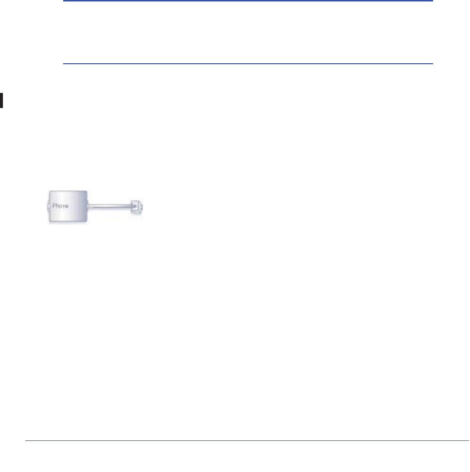
One-Line ADSL Microfilter (Not Included)
Plug the ADSL microfilter into the wall outlet and plug your phone equipment into the jack
labeled Phone. The wireless modem router plugs directly into a separate ADSL line. Plugging
the wireless modem router into the phone jack blocks the Internet connection. If you do not
have a separate ADSL line for the router, the best thing to do is to use an ADSL microfilter
with a built-in splitter.
Plugs into ADSL line
Figure 5. One-line ADSL microfilter
Second best when you do not have a separate ADSL line for the router is to get a separate
splitter. To use a one-line filter with a separate splitter, insert the splitter into the phone outlet,
connect the one-line filter to the splitter, and connect the phone to the filter.

Chapter 1. Hardware Setup | 19
N600 Wireless Dual Band Gigabit ADSL2+ Modem Router DGND3700 User Manual
Two-Line ADSL Microfilter (Included)
Use an ADSL microfilter with a built-in splitter when there is a single wall outlet that provides
connectivity for both the wireless modem router and your telephone equipment. Plug the
ADSL microfilter into the wall outlet, plug your phone equipment into the jack labeled Phone,
and plug the wireless modem router into the jack labeled ADSL.
Plugs into the ADSL line
Figure 6. Two-line ADSL microfilter with built-in splitter
Summary
•One-line ADSL microfilter (not included). Use with a phone or fax machine.
•Splitter (not included). Use with a one-line ADSL microfilter to share an outlet with a
phone and the wireless modem router.
•Two-line ADSL microfilter with built-in splitter (included). Use to share an outlet with a
phone and the wireless modem router.
20 | Chapter 1. Hardware Setup
N600 Wireless Dual Band Gigabit ADSL2+ Modem Router DGND3700 User Manual
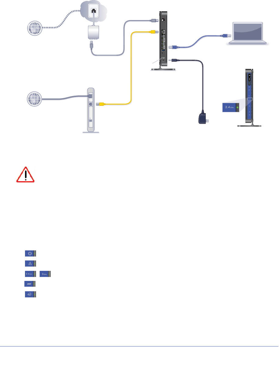
Cable Your N600 Wireless Modem Router
The installation guide that came in the box has a cabling diagram on the first page.
ADSL
Phone
Line
Laptop or desktop
computer
Fiber/Cable modem
Step 1:
Connect to ADSL.
If connecting directly
to a DSL line.
Connect to Ethernet WAN.
If connecting to a
Fiber/Cable modem.
Step 2:
Cable your computer.
Step 3:
Power on your router.
Wait until the 2.4 GHz
Wireless LED turns solid
green.
Note: Add an ADSL filter for every
telephone on the same phone line
as your wireless modem router.
Internet
Internet
Power on/off
N600 Wireless Modem Router
Note: Keep the DGND3700
N600 Wireless Modem Router
in a vertical position.
Connect to Internet with ADSL or Ethernet WAN.
Phone cable
Ethernet cable
Ethernet cable
“not included”
Power adapter
N600 Wireless Modem Router
2.4 GHz
Wireless LED
Figure 7. Cabling Diagram
CAUTION:
Incorrectly connecting a filter to your wireless modem router blocks your
ADSL connection.
Verify the Cabling
Verify that your router is cabled correctly by checking the wireless modem router LEDs. Turn
on the wireless router by pressing the On/Off button on the back.
•The Power LED is green when the modem router is turned on.
•The LAN port is green when a PC is cabled to the router by an Ethernet cable.
•The wireless LEDs are lit when the modem router is turned on.
•The DSL LED is green when you have an ADSL connection.
•The Internet LED is red when there is no Internet connection.
Turn on your computer. If software usually logs you in to your Internet connection, do not run
that software. Cancel it if it starts automatically.

Chapter 1. Hardware Setup | 21
N600 Wireless Dual Band Gigabit ADSL2+ Modem Router DGND3700 User Manual
For More Information
For more information on the topics covered in this manual, visit the Support website at
http://support.netgear.com.

Chapter 2. Router Internet Setup | 22
2
2. Router Internet Setup
Connecting to the network
This chapter explains how to set up your Internet connection using one of two methods: Setup
Wizard or manual setup. If you have already set up your router using one of these methods, the
initial router setup is complete. Refer to this chapter if you want to become familiar with the
router menus, view or adjust the initial settings, or change the router password and login
time-out.
This chapter contains the following sections:
•Router Setup Preparation
•Log In to the N600 Modem Router
•Upgrade Router Firmware
•Router Interface
•Setup Wizard
•Manual Setup (Basic Settings)
•ADSL Settings
•Unsuccessful Internet Connection
•Change Password and Login Time-Out
•Log Out Manually
•Types of Logins

Chapter 2. Router Internet Setup | 23
N600 Wireless Dual Band Gigabit ADSL2+ Modem Router DGND3700 User Manual
Router Setup Preparation
You can set up your wireless modem router with the Setup Wizard as described in Setup
Wizard on page 27 or manually as described in Manual Setup (Basic Settings) on page 28.
However, before you start the setup process, you need to have your ISP information on hand
and make sure the laptops, PCs, and other devices in the network have the settings
described here.
Note: If you have a Macintosh or Linux system, you have to use the
manual setup method.
Use Standard TCP/IP Properties for DHCP
If you configured your computer to use a static IP address, you need to change the settings
back so that it uses Dynamic Host Configuration Protocol (DHCP). See Appendix A,
Supplemental Information for more information.
Replace an Existing Router
To replace an existing router, disconnect it completely from your network and set it aside
before starting the router setup.
Adapters and Security Settings
A wireless adapter is the wireless radio in your PC or laptop that lets the PC or laptop
connect to a wireless network. Most PCs and laptops come with an adapter already installed,
but if it is outdated or slow, you can purchase a USB adapter to plug into a USB port.
Make sure the wireless adapter in each computer in your wireless network supports the same
security settings as the wireless modem router. See Wireless Security Requirements and
Recommendations on page 36 for information about the router’s security settings.
Note: If you connect devices to your modem router using WPS as
described in Wi-Fi Protected Setup (WPS) Method on page 39,
those devices assume the security settings of the router.
Gather ISP Information
You need the following information to set up your wireless modem router and to check that
your Internet configuration is correct. Your Internet Service Provider (ISP) should have
provided you with all of the information needed to connect to the Internet. If you cannot locate
24 | Chapter 2. Router Internet Setup
N600 Wireless Dual Band Gigabit ADSL2+ Modem Router DGND3700 User Manual
this information, ask your ISP to provide it. When your Internet connection is working, you no
longer need to launch the ISP’s login program on your computer to access the Internet. When
you start an Internet application, your wireless modem router automatically logs you in.
•Active Internet service provided by an ADSL account
•The ISP configuration information for your ADSL account
-ISP login name and password
-ISP Domain Name Server (DNS) addresses
-Fixed or static IP address
-Host and domain names
-Depending on how your ISP set up your Internet account, you could need to know
one or more of these settings for a manual setup:
-Virtual path identifier (VPI) and virtual channel identifier (VCI) parameters
-Multiplexing method
-Host and domain names
Log In to the N600 Modem Router
Log in to the wireless modem router to view or change settings or to set up the wireless
modem router.
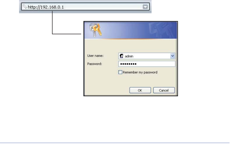
1. Type http://192.168.0.1 in the address field of your browser and press Enter to display
the login window. You can also enter either of these addresses to access the wireless
modem router: http://www.routerlogin.net or http://www.routerlogin.com.
Figure 8. Log in with user name and password
2. When prompted, enter admin for the router user name and password for the router
password, both in lowercase letters.

Chapter 2. Router Internet Setup | 25
N600 Wireless Dual Band Gigabit ADSL2+ Modem Router DGND3700 User Manual
Note: The router user name and password are probably different from the
user name and password for logging in to your Internet connection.
See Types of Logins on page 33 for more information.
The router menus display where you can do things like changing settings or adding other
devices to your network. See Router Interface on page 26 for a brief description of the
available functionality, and Wi-Fi Protected Setup (WPS) Method on page 39 for
information about adding devices to your network.
If you do not see the login prompt:
1. Check the LEDs on the router front panel to make sure that the modem router is
plugged into an electrical outlet, its power is on, and the Ethernet cable between your
computer and the router is connected to a LAN port.
2. If you connected the Ethernet cable and quickly launched your browser and typed in the
router URL, your computer might need a minute or two to recognize the LAN connection.
Relaunch your browser and try again.
3. If you are having trouble accessing the router wirelessly, NETGEAR recommends that
during setup you use an Ethernet cable to connect your computer so that you can log in to
the wireless modem router.
Note: If you cannot connect to the wireless router, check the Internet
Protocol (TCP/IP) properties in the Network Connections section of
your PC Control Panel. They should be set to obtain both IP and
DNS server addresses automatically.
Upgrade Router Firmware
When you log in and if you are connected to the Internet, the Firmware Upgrade Assistant
screen displays so you can upgrade to the latest available firmware. See Chapter 5, Network
Maintenance, for more information about upgrading firmware.
1. Click Yes to check for new firmware (recommended). The modem router checks the
NETGEAR database for new firmware.
2. If no new firmware is available, click No to exit. You can check for new firmware later.
3. If new firmware is available, click Yes to upgrade the router with the latest firmware. After the
upgrade, the router restarts.
CAUTION:
Do not try to go online, turn off the router, shut down the computer, or do
anything else to the router until the router finishes restarting and the
Ready light has stopped blinking for several seconds.
26 | Chapter 2. Router Internet Setup
N600 Wireless Dual Band Gigabit ADSL2+ Modem Router DGND3700 User Manual
You cannot upgrade firmware until you have established your Internet connection as
described in Setup Wizard on page 27.
Router Interface
The router interface gives you access to the router’s current settings so you can view or
change them (if needed). The left column has the router menus, and the right column
provides online help. The middle column is the screen for the current menu option.
Figure 9. Router interface
Setup Wizard
Specify the language, location, and automatically detect the Internet connection. See Setup
Wizard on page 27.
Add WPS Client
Add WPS-compatible wireless devices and other equipment to your wireless network. See
Add Clients (Devices) to Your Network on page 39.
Setup Menu
Set, upgrade, and check the ISP and wireless network settings of your router. See Manual
Setup (Basic Settings) on page 28 and ADSL Settings on page 31. See also Chapter 3,
Wireless Settings, for information about preset and basic security settings.
Chapter 2. Router Internet Setup | 27
N600 Wireless Dual Band Gigabit ADSL2+ Modem Router DGND3700 User Manual
USB Storage Menu
Add removable storage to your network. See Chapter 6, USB Storage.
Content Filtering Menu
View and configure the router firewall settings to prevent objectionable content from reaching
your PCs. See Chapter 4, Security Settings.
Maintenance Menu
Administer and maintain your router and network. See Chapter 5, Network Maintenance.
Advanced Menu
Set the router up for unique situations such as when remote access by IP or by domain name
from the Internet is needed. See Chapter 8, Advanced Settings. Using this menu requires a
solid understanding of networking concepts.
Advanced – VPN Menu
Set up secure encrypted communications. See Chapter 7, Virtual Private Networking. Using
this menu requires a solid understanding of networking concepts.
Web Support
Go to the NETGEAR support site to get information, help, and product documentation. These
links work once you have an Internet connection.
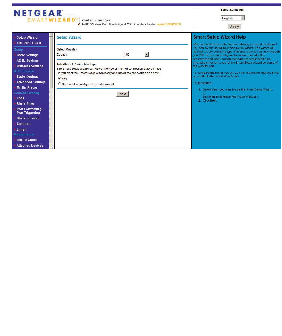
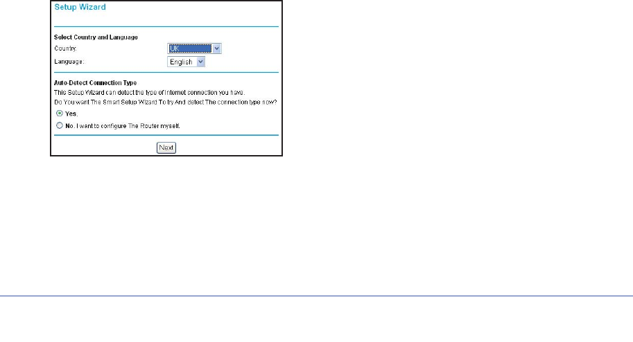
Setup Wizard
You have to log in to the modem router to set the country, language, and Internet connection.
1. Select Setup Wizard from the top of the router menus to display the following screen:
Figure 10. Country and language settings in Setup Wizard
2. Select your country and language:
•Country. It is important to specify the location where the wireless modem router
operates so that the Internet connection works correctly. Defaults to UK.
•Language. Defaults to English. You can select another language if you prefer.

28 | Chapter 2. Router Internet Setup
N600 Wireless Dual Band Gigabit ADSL2+ Modem Router DGND3700 User Manual
3. Select either Yes or No, I want to configure the Router myself. If you select No, proceed
to Manual Setup (Basic Settings) on page 28.
4. If you selected Yes, click Next.
With automatic Internet detection, the Setup Wizard searches your Internet connection
for servers and protocols to determine your ISP configuration.
Note: The Setup Wizard cannot detect a Point-to-Point Tunneling Protocol
(PPTP) connection. If your ISP uses PPTP, you have to set your
Internet connection through the screen described in Manual Setup
(Basic Settings) described on 28.
Manual Setup (Basic Settings)
The Basic Settings screen displays when you select No. I want to configure the Router myself
in the Setup Wizard and is also available from the router menus. It is where you view or
change ISP information. The fields that display vary depending on whether or not your
Internet connection requires a login.
Note: Check that the country and language are set as described Setup
Wizard on page 27 before proceeding with the manual setup.
1. Select Set Up > Basic Settings and select Yes or No depending on whether or not
your ISP requires a login. Figure 11, Basic Settings screen without (left) and with (right)
login. shows both forms of the Basic Settings screen.
•Yes. Select the encapsulation method and enter the login name. If you want to
change the login time-out, enter a new value in minutes.
•No. Enter the account and domain names, as needed.
2. Enter the settings for the IP address and DNS server. The default ADSL settings usually
work fine. If you have problems with your connection, check the ADSL settings and see
ADSL Settings on page 31 for more information.
3. If no login is required, you can specify the MAC Address setting.
4. Click Apply to save your settings.
5. Click Test to test your Internet connection. If the NETGEAR website does not appear within
1 minute, and see Troubleshooting on page 143.
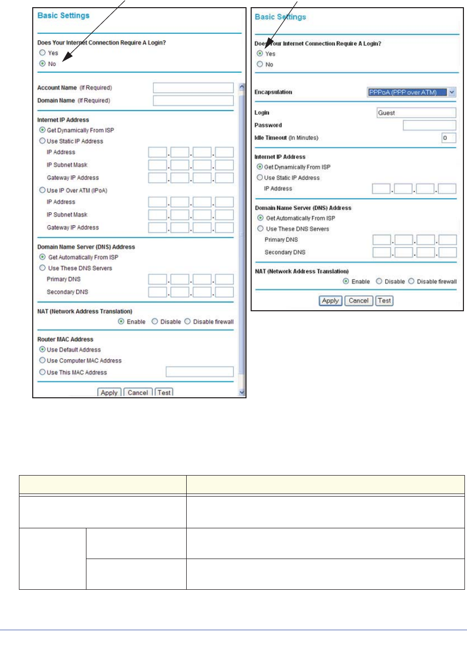
ISP does not require login ISP does require login
Chapter 2. Router Internet Setup | 29
N600 Wireless Dual Band Gigabit ADSL2+ Modem Router DGND3700 User Manual
Figure 11. Basic Settings screen without (left) and with (right) login.
The following table explains all of the possible fields in the Basic Settings screen. Note that
which fields appear in this screen depends on whether or not a login is required..
Table 11. Basic Settings Screen Description
Settings Description
Does Your ISP Require a Login? • Yes
• No
These fields
display only if
no login is
required.
Account Name
(If required) Enter the account name provided by your ISP. This might also be
called the host name.
Domain Name
(If required) Enter the domain name provided by your ISP.

30 | Chapter 2. Router Internet Setup
N600 Wireless Dual Band Gigabit ADSL2+ Modem Router DGND3700 User Manual
These fields
display only if
your ISP
requires a
login.
Encapsulation Encapsulation is a method for enclosing multiple protocols. PPP
stands for Point-to-Point Protocol. The choices are:
• PPPoE (PPP over Ethernet)
• PPPoA (PPP over ATM)
Login The login name provided by your ISP. This is often an email address.
Password The password that you use to log in to your ISP.
Idle Timeout (In
minutes) If you want to change the login timeout, enter a new value in minutes.
This determines how long the wireless modem router keeps the
Internet connection active after there is no Internet activity from the
LAN. Entering a value of 0 (zero) means never log out.
Internet IP
Address •Get Dynamically from ISP. Your ISP uses DHCP to assign your IP
address. Your ISP automatically assigns these addresses.
•Use Static IP Address. Enter the IP address, IP subnet mask, and
the gateway IP address that your ISP assigned. The gateway is the
ISP’s wireless modem router to which your wireless modem router
will connect.
This field displays only
if no login is required. •Use IP Over ATM (IPoA). Your ISP uses classical IP addresses
(RFC 1577). Enter the IP address, IP subnet mask, and gateway IP
addresses that your ISP assigned.
Domain Name Server (DNS) Address The DNS server is used to look up site addresses based on their
names.
•Get Automatically from ISP. Your ISP uses DHCP to assign your
DNS servers. Your ISP automatically assigns this address.
•Use These DNS Servers. If you know that your ISP does not
automatically transmit DNS addresses to the wireless modem
router during login, select this option, and enter the IP address of
your ISP’s primary DNS server. If a secondary DNS server address
is available, enter it also.
Table 11. Basic Settings Screen Description
Settings Description

Chapter 2. Router Internet Setup | 31
N600 Wireless Dual Band Gigabit ADSL2+ Modem Router DGND3700 User Manual
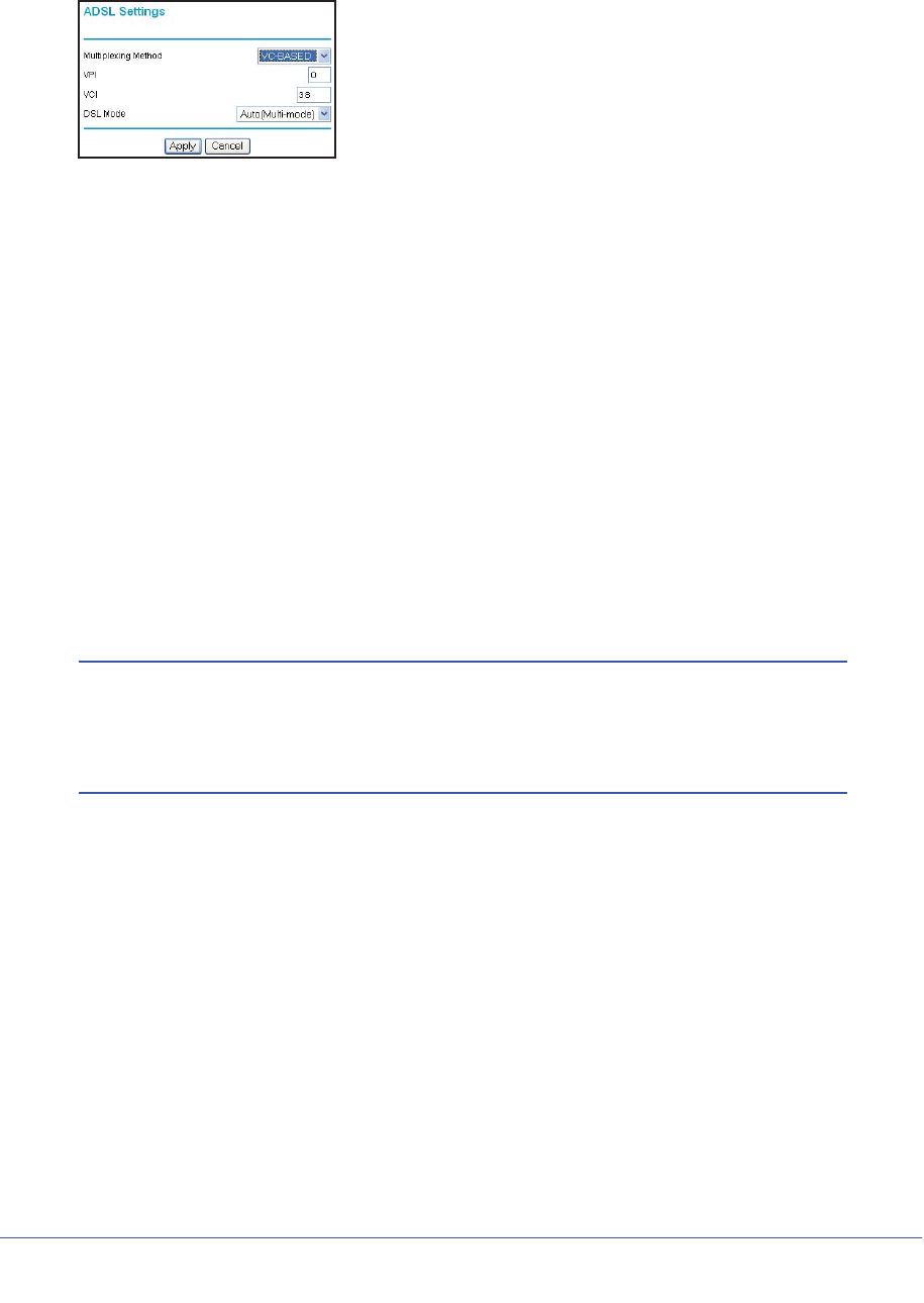
ADSL Settings
ADSL settings of your wireless modem router work fine for most ISPs. However, some ISPs
use a specific multiplexing method and virtual circuit number for the virtual path identifier
(VPI) and virtual channel identifier (VCI).
Note: You must use the Setup Wizard to select the correct country for the
default ADSL settings to work.
If your ISP provided you with a multiplexing method or VPI/VCI number, enter the setting:
NAT (Network Address Translation) NAT automatically assigns private IP addresses (10.1.1.x) to
LAN-connected devices.
•Enable. Usually NAT is enabled.
•Disable. This disables NAT, but leaves the firewall active. Disable
NAT only if you are sure you do not need it. When NAT is disabled,
only standard routing is performed by this router. Classical routing
lets you directly manage the IP addresses that the wireless modem
router uses. Classical routing should be selected only by
experienced users.1
•Disable firewall. This disables the firewall in addition to disabling
NAT. With the firewall disabled, the protections usually provided to
your network are disabled.
These fields
display only if
no login is
required.
Router MAC Address The Ethernet MAC address used by the wireless modem router on
the Internet port. Some ISPs register the MAC address of the
network interface card in your computer when your account is first
opened. They will then accept traffic only from the MAC address of
that computer. This feature allows your wireless modem router to use
your computer’s MAC address (this is also called cloning).
•Use Default Address. Use the default MAC address.
•Use Computer MAC Address. The wireless modem router will
capture and use the MAC address of the computer that you are
now using. You must be using the one computer that is allowed by
the ISP.
•Use This MAC Address. Enter the MAC address that you want to
use.
1. Disabling NAT reboots the wireless modem router and resets its configuration settings to the factory defaults.
Disable NAT only if you plan to set up the wireless modem router in a setting where you will be manually
administering the IP address space on the LAN side of the router.
Table 11. Basic Settings Screen Description
Settings Description
32 | Chapter 2. Router Internet Setup
N600 Wireless Dual Band Gigabit ADSL2+ Modem Router DGND3700 User Manual
1. Select Setup > ADSL Settings to display the following screen:
Figure 12. ADSL Settings screen
2. In the Multiplexing Method drop-down list, select LLC-based or VC-based.
3. For the VPI, type a number between 0 and 255. The default is 8 for the U.S. version, 0 for
the world wide version, and 1 for the German version.
4. For the VCI, type a number between 32 and 65535. The default is 35 for the U.S. version,
38 for the worldwide version, and 32 for the German version.
5. Click Apply.
Unsuccessful Internet Connection
1. Review your settings to be sure you have selected the correct options and typed
everything correctly.
2. Contact your ISP to verify that you have the correct configuration information.
3. Read Chapter 9, Troubleshooting. If problems persist, register your NETGEAR product and
contact NETGEAR Technical Support.
Note: If you cannot connect to the wireless router, check the Internet
Protocol (TCP/IP) properties in the Network Connections section of
your PC Control Panel. They should be set to obtain both IP and
DNS server addresses automatically.
Change Password and Login Time-Out
For security reasons, the wireless modem router has its own user name and password that
default to admin and password. You can and should change this password to a secure
password that is easy to remember. The ideal password contains no dictionary words from
any language and is a mixture of upper case and lower case letters, numbers, and symbols.
It can be up to 30 characters.
Chapter 2. Router Internet Setup | 33
N600 Wireless Dual Band Gigabit ADSL2+ Modem Router DGND3700 User Manual
Note: The router user name and password are not the same as the user
name and password for logging in to your Internet connection. See
Types of Logins on page 33 for more information about login types.
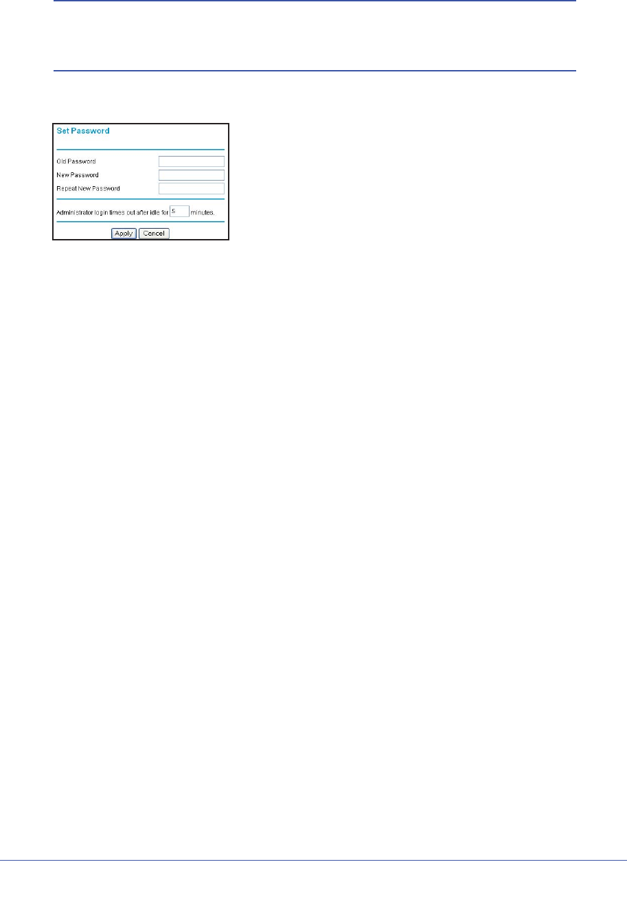
1. Select Maintenance > Set Password to display the following screen:.
Figure 13. Set router login password
2. Enter the old password.
3. Enter the new password twice.
4. Change the login time-out to a value between 1 and 99 minutes if the default value of 5
minutes does not meet your needs.
The administrator’s login to the wireless modem router configuration times out after a
period of inactivity to prevent someone else from accessing the router interface when you
step away.
5. Click Apply to save your changes.
After changing the password, you are required to log in again to continue the
configuration. If you have backed up the wireless modem router settings previously, you
should do a new backup so that the saved settings file includes the new password. See
Back Up on page 66 for information about backing up your network configuration.
Log Out Manually
The router interface provides a Logout command at the bottom of the router menus. Log out
when you expect to be away from your computer for a relatively long period of time.
Types of Logins
There are three separate types of logins that have different purposes. It is important that you
understand the difference so that you know which login to use when.
•Router login logs you in to the router interface. See Log In to the N600 Modem Router
on page 24 for details about this login.
•ISP login logs you in to your Internet service. Your service provider has provided you with
this login information in a letter or some other way. If you cannot find this login
information, contact your service provider.

34 | Chapter 2. Router Internet Setup
N600 Wireless Dual Band Gigabit ADSL2+ Modem Router DGND3700 User Manual
•Wi-Fi network name and passphrase logs you in to your wireless network. This login is
preconfigured and can be found on the label on the bottom of your unit. See Chapter 3,
Wireless Settings, for more information.

Chapter 3. Wireless Settings | 35
3
3. Wireless Settings
Protecting your wireless network
This chapter describes how to use the Wireless Settings screens to view and change (if needed)
your wireless network settings. Security features to prevent objectionable content from reaching
your PCs are covered in Chapter 4, Security Settings.
This chapter contains the following sections:
•Wireless Security Requirements and Recommendations
•Wireless Security Basics
•Add Clients (Devices) to Your Network
•Wireless Settings Screen
Note: If you use the Internet for activities like purchases or banking, those
Internet sites use a highly secure data encryption protocol called
Secure Sockets Layer (SSL). If a website uses SSL, the address
begins with https instead of http. If you do not see https, it is more
secure to do your business in person or over the phone.

36 | Chapter 3. Wireless Settings
N600 Wireless Dual Band Gigabit ADSL2+ Modem Router DGND3700 User Manual
Wireless Security Requirements and Recommendations
You must set the following security:
•Wi-Fi network name (SSID) identifies your network so devices can find it.
-The default SSID for the 2.4 GHz wireless network is NETGEAR.
-The default SSID for the 5 GHz wireless is NETGEAR-5G.
•Security option is the type of security protocol applied to your wireless network. The
security protocol in force encrypts data transmissions and ensures that only trusted
devices receive authorization to connect to your network. The recommended security
option is WPA-PSK/WPA2-PSK mixed mode described in Wireless Security Options on
page 37.
•Passphrase controls access to your network. Devices that know the SSID and the
passphrase can find your wireless network and connect.
-Use a passphrase for the 2.4 GHz wireless network that is easy for you to remember,
but hard for others to guess.
-For maximum security, use a different passphrase for the 5 GHz wireless network that
is easy for you to remember, but hard for others to guess.
Note: Your network names (SSIDs) and passphrases are case-sensitive.
Your network name, security method, and passphrase must be the
same for all the wireless devices connected to your router on a
network.
Wireless Security Basics
Unlike wired network data, wireless data transmissions extend beyond your walls and can be
received by any device with a compatible wireless adapter (radio). For this reason, it is very
important to maintain the preset security and understand the other security features available
to you. Besides the preset security settings described above, your wireless modem router
has the security features described here and in Chapter 4, Security Settings.
•Turn off wireless connectivity
•Disable SSID broadcast
•Restrict access by MAC address
•Wireless security options

Chapter 3. Wireless Settings | 37
N600 Wireless Dual Band Gigabit ADSL2+ Modem Router DGND3700 User Manual
Turn Off Wireless Connectivity
You can completely turn off the wireless connectivity of the wireless modem router by
pressing the Wireless On/Off button on its front panel . For example, if you use your
notebook computer to wirelessly connect to your wireless modem router and you take a
business trip, you can turn off the wireless portion of the modem router while you are
traveling. Other members of your household who use computers connected to the wireless
modem router through Ethernet cables can still use the wireless modem router.
Disable SSID Broadcast
By default, the wireless modem router broadcasts its Wi-Fi network name (SSID) so devices
can find it. If you change this setting to not allow the broadcast, wireless devices will not find
your wireless modem router unless they are configured with the same SSID. See Wireless
Access Point Settings on page 43 for the procedure.
Note: Turning off SSID broadcast nullifies the wireless network discovery
feature of some products such as Windows XP, but the data is still
fully exposed to a determined snoop using specialized test
equipment like wireless sniffers. If you allow the broadcast, be sure
to keep wireless security enabled.
Restrict Access by MAC Address
You can enhance your network security by allowing access to only specific PCs based on
their Media Access Control (MAC) addresses. You can restrict access to only trusted PCs so
that unknown PCs cannot wirelessly connect to the wireless modem router. MAC address
filtering adds an obstacle against unwanted access to your network, but the data broadcast
over the wireless link is fully exposed (unencrypted).The Wireless Station Access List
determines which wireless hardware devices are allowed to connect to the wireless modem
router by MAC address. See Wireless Station Access List Settings on page 43 for the
procedure.
Wireless Security Options
A security option is the type of security protocol applied to your wireless network. The
security protocol in force encrypts data transmissions and ensures that only trusted devices
receive authorization to connect to your network. There are two types of encryption: Wired
Equivalent Privacy (WEP) and Wi-Fi Protected Access (WPA). WPA has several options
including pre-shared key (PSK) encryption and 802.1x encryption for enterprises.
This section presents an overview of the security options and provides guidance on when to
use which option. Note that it is also possible to disable wireless security. NETGEAR does
not recommend this.

38 | Chapter 3. Wireless Settings
N600 Wireless Dual Band Gigabit ADSL2+ Modem Router DGND3700 User Manual
WEP Encryption
WEP uses an old encryption method and can be easily decoded with today's powerful
computers. Use this mode only when you have a very old legacy wireless client that does not
support WPA-PSK. The Wi-Fi alliance highly recommends against using WEP and plans to
make it obsolete. If you do decide to use WEP, see Set WEP Encryption and Passphrase on
page 45 for the procedure.
WPA Encryption
WPA encryption is built into all hardware that has the Wi-Fi-certified seal. This seal means
the product is authorized by the Wi-Fi Alliance (http://www.wi-fi.org/) because it complies with
the worldwide single standard for high-speed wireless local area networking. For information
about how to use the WPA home options, see Change WPA Security Option and Passphrase
on page 45.
WPA-PSK uses a much stronger encryption algorithm than WEP so it is harder to decode.
This option uses a passphrase to perform the authentication and generate the initial data
encryption keys. Then it dynamically varies the encryption key. WPA-PSK uses Temporal Key
Integrity Protocol (TKIP) data encryption, implements most of the IEEE 802.11i standard, and
is designed to work with all wireless network interface cards, but not all wireless access
points. It is superseded by WPA2-PSK.
WPA2-PSK is the strongest. It is advertised to be theoretically indecipherable due to the
greater degree of randomness in encryption keys that it generates. WPA2-PSK gets higher
speed because it is usually implemented through hardware, while WPA-PSK is usually
implemented through software. WPA2-PSK uses a passphrase to authenticate and generate
the initial data encryption keys. Then it dynamically varies the encryption key.
WPS-PSK + WPA2-PSK Mixed Mode is the preconfigured security mode on the wireless
modem router. NETGEAR recommends mixed mode because it provides broader support for
all wireless clients. WPA2-PSK clients get higher speed and security, and WPA-PSK clients
get decent speed and security. The product documentation for your wireless adapter and
WPA client software should have instructions about configuring their WPA settings.
WPA-802.1x is enterprise-level security and requires an authentication server to recognize
and authorize client access. The authentication server is called Remote Authentication Dial
In User Service (RADIUS). Every wireless client has a user login on the RADIUS server, and
the wireless modem router has a client login on the RADIUS server. Data transmissions are
encrypted with an automatically generated key. For information about how to use the WPA
enterprise option, see Set WPA-802.1x Server and Passphrase on page 45.

Chapter 3. Wireless Settings | 39
N600 Wireless Dual Band Gigabit ADSL2+ Modem Router DGND3700 User Manual
Add Clients (Devices) to Your Network
Choose either the manual or the WPS method to add wireless devices, including guest
devices, and other equipment to your wireless network.
Manual Method
1. Open the software that manages your wireless connections on the wireless device
(laptop computer, gaming device, iPhone) that you want to connect to your router. This
software scans for all wireless networks in your area.
2. Look for your network and select it. If you did not change the name of your network during
the setup process, look for the default Wi-Fi network name (SSID) and select it. The default
Wi-Fi network name (SSID) is located on the product label on the bottom of the router.
3. Enter the wireless modem router passphrase and click Connect. The default wireless
modem router passphrase is located on the product label on the bottom of the router.
4. Repeat steps 1–3 to add other wireless devices.
Wi-Fi Protected Setup (WPS) Method
Wi-Fi Protected Setup (WPS) is a standard for easily adding computers and other devices to
a home network while maintaining security. To use WPS, make sure that all wireless devices
to be connected to the network are Wi-Fi certified and support WPS. During the connection
process, the client gets the security settings from the router so that every device in the
network has the same security settings.
Note: However, if you find that the router is generating new security
settings for each added device, it means that the default value for
Keep Existing Wireless Settings has changed. See WPS Settings on
page 129 for more information about this setting.
All Wi-Fi-certified and WPS-capable products are compatible with the NETGEAR products
that have Push 'N' Connect, which is based on WPS1. For information about how to view a
list of all wireless and wired devices connected to your modem router, see View Attached
Devices on page 71.
Note: WEP security does not support WPS. If you try to use WPS to
connect a WEP device to your network, it will not connect.
You can use the WPS (Push 'N' Connect) or router interface method to add wireless devices
and other equipment to your wireless network.
1. For a list of other Wi-Fi-certified products available from NETGEAR, go to http://www.wi-fi.org.
40 | Chapter 3. Wireless Settings
N600 Wireless Dual Band Gigabit ADSL2+ Modem Router DGND3700 User Manual
WPS (Push 'N' Connect) Method
If your wireless device supports WPS (Push 'N' Connect), follow these steps:
1. Press the WPS button on the router front panel .
2. Within 2 minutes, press the WPS button on your wireless device or follow the WPS
instructions that came with the device. The device is now connected to your router.
3. Repeat steps 1–2 to add other WPS wireless devices.
Router Interface Method
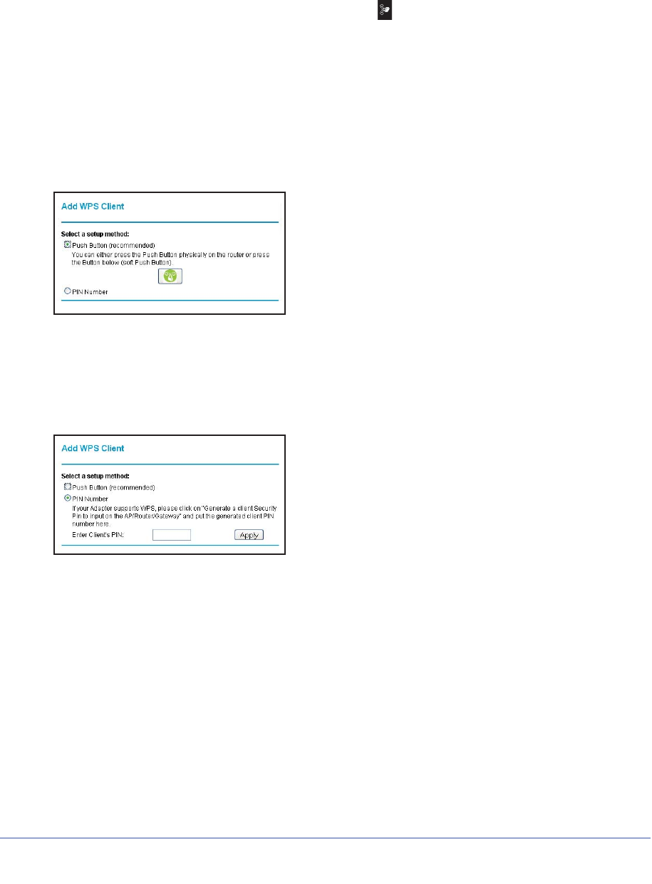
1. Select Add WPS Client at the top of the router menus. If you cannot select Add WPS
Client, select Setup > Wireless Settings and make sure WPS is selected.
2. Click Next. The following screen lets you select the method for adding the WPS client.
Figure 14. Add WPS Client with push button method
3. Select either Push Button or PIN Number. With either method, the client wireless device
attempts to detect the WPS signal from the wireless modem router and establish a
wireless connection in the time allotted.
The PIN method displays this screen so you can enter the client security PIN number:
Figure 15. Add WPS Client with PIN number method
•While the wireless modem router attempts to connect to a WPS-capable device, the
WPS LED on the front of the wireless modem router blinks green. When the wireless
modem router establishes a WPS connection, the LED is solid green.
•If a connection is established, the wireless modem router WPS screen displays a
confirmation message.
4. Repeat to add another WPS client to your network.

Chapter 3. Wireless Settings | 41
N600 Wireless Dual Band Gigabit ADSL2+ Modem Router DGND3700 User Manual
Wireless Settings Screen
The Wireless Settings screen lets you view or configure the wireless network configuration.
Once you have established basic wireless connectivity, you can enable security settings
appropriate to your needs.
Note: If you use a wireless computer to change the wireless network
name (SSID) or other wireless security settings, you are
disconnected when you click Apply. To avoid this problem, use a
computer with a wired connection to access the modem router.
Consider Every Device on Your Network
Before you begin, check the following:
•Every wireless computer has to be able to obtain an IP address by DHCP from the router
as described in Use Standard TCP/IP Properties for DHCP on page 23.
•Each computer or wireless adapter in your network must have the same SSID and
wireless mode (bandwidth/data rate) as the router. Check that the wireless adapter on
each computer can support the mode and security option you want to use.
•The security option on each wireless device in the network must match the router. For
example, if you select a security option that requires a passphrase, be sure to use same
passphrase for each wireless computer in the network.
42 | Chapter 3. Wireless Settings
N600 Wireless Dual Band Gigabit ADSL2+ Modem Router DGND3700 User Manual
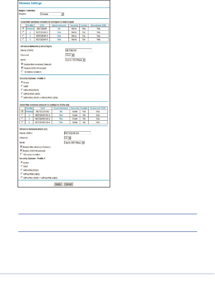
Configure Wireless Settings
1. Select Setup > Wireless Settings to display the following screen.
Figure 16. Wireless Settings screen
2. Make any changes that are needed and click Apply when done to save your settings.
Note: The screen sections, settings, and procedures are explained in the
following sections.
3. After you finish adjusting settings and click Apply, configure and test your computers for
wireless connectivity:

Chapter 3. Wireless Settings | 43
N600 Wireless Dual Band Gigabit ADSL2+ Modem Router DGND3700 User Manual
a. Program the wireless adapter of your computers to have the same SSID and channel
that you specified in the router.
b. Check that the adapters have a wireless link and can obtain an IP address by DHCP
from the wireless modem router.
Wireless Network Settings
Name (SSID). The SSID is also known as the wireless network name. Enter a 32-character
(maximum) name in this field. This field is case-sensitive.
Region. The location where the wireless modem router is used. It might not be legal to
operate the wireless modem router in a region other than the regions listed.
Channel. The wireless channel used by the gateway: 1 through 13. Do not change the
channel unless you experience interference (shown by lost connections or slow data
transfers). If this happens, experiment with different channels to see which is the best.
Mode. Up to 145 Mbps is the default and allows 802.11n and 802.11g wireless devices to join
the network. g & b supports up to 54 Mbps. Up to 65 Mbps supports up to 65 Mbps.
Wireless Access Point Settings
Enable. When this check box is not selected, the wireless signal in the router so it can accept
wireless clients. When not enabled, the router accepts wired clients only. This check box is
selected by default.
Allow Broadcast of Name (SSID). This setting allows the wireless modem router to
broadcasts its SSID so wireless stations can see this wireless name (SSID) in its scanned
network list. This check box is selected by default. To turn off the SSID broadcast, clear the
Allow Broadcast of Name (SSID) check box and click Apply.
Wireless Isolation. When this check box is selected, wireless stations cannot communicate
with each other or with stations on the wired network. This check box is not selected by
default.
Wireless Station Access List Settings
The Wireless Stations Access List lets you restrict access to your network to a specific list of
devices based on their MAC addresses. This section explains how to set up the list.
1. On the Wireless Settings screen, click the Setup Access List button to display the
Wireless Station Access List screen shown in Figure 17, Wireless Station Access List
and introduced here:
•The Turn Access Control On check box at the top is not selected by default to allow
any computer configured with the correct wireless network name (SSID) and
passphrase to access the network.
•Trusted Wireless Stations lists the trusted computers that have access to your
network.
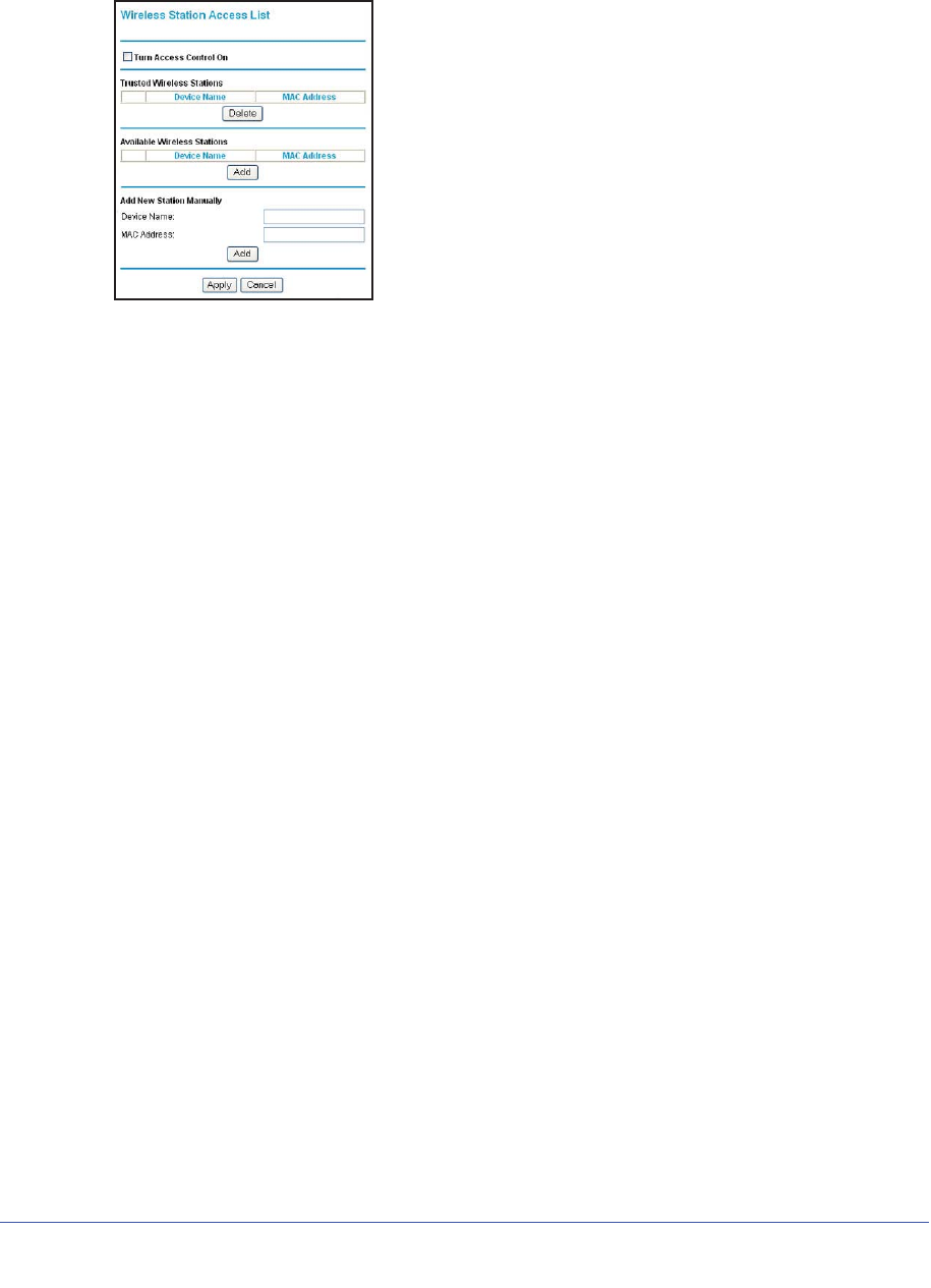
44 | Chapter 3. Wireless Settings
N600 Wireless Dual Band Gigabit ADSL2+ Modem Router DGND3700 User Manual
•Available Wireless Stations lists the currently untrusted computers that are connected
to your network.
Figure 17. Wireless Station Access List
2. Select the Turn Access Control On check box to enable access restriction by MAC
address.
3. In the Add New Station Manually list, click Add to add your computer’s MAC address so you
do not lose your wireless connection when you click Apply. If you lose your wireless
connection, you have to access the wireless modem router from a wired computer or from a
wireless computer that is on the access control list.
4. If a wireless station that you want to add to the Trusted Wireless Stations list is connected to
the network, select it from the Available Wireless Stations list and click Add.
5. If the wireless station is not currently connected, you can enter its address manually. The
MAC address is usually printed on the wireless card, or it might appear in the wireless
modem router’s DHCP table. The MAC address is 12 hexadecimal digits.
You can also copy and paste the MAC addresses from the wireless modem router’s
Attached Devices screen (see View Attached Devices on page 71) into the MAC Address
field. To do this, configure each wireless computer to obtain a wireless link to the wireless
modem router. The computer should then appear in the Attached Devices screen.
6. Click Apply to save your settings and return to the Wireless Settings screen.
Security Options Settings
The Security Options section of the Wireless Settings screen lets you change the security
option and passphrase. See Wireless Security Options on page 37 for an explanation of the
security options and when to use which one. Please note that NETGEAR recommends that
you not change the security option or passphrase, but if you want to change these
settings, this section explains how. Do not disable security.
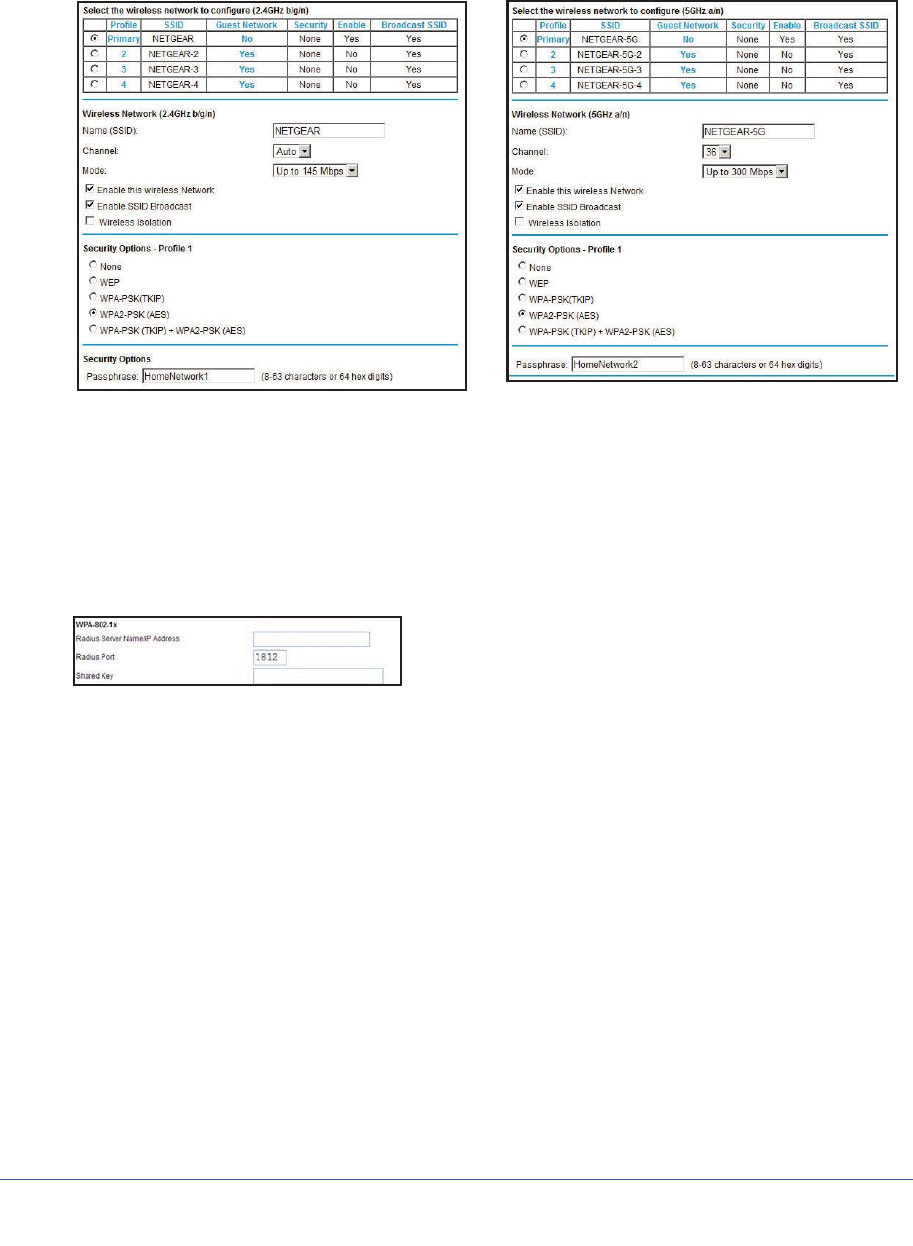
Chapter 3. Wireless Settings | 45
N600 Wireless Dual Band Gigabit ADSL2+ Modem Router DGND3700 User Manual
Change WPA Security Option and Passphrase
1. In the Security Options sections, select the WPA options you want.
Figure 18. WPA2-PSK Security Encryption
2. In the Passphrase field that displays when you select a WPA security option, enter the
network keys (passphrases) that you want to use. They are text string from 8 to 63
characters (in Figure 18, HomeNetwork1 and HomeNetwork2 are used as examples).
Set WPA-802.1x Server and Passphrase
1. In the Security Options section, select WPA-802.1x to display the following fields:
Figure 19. WPA-802.1x Settings
2. In the Radius Server Name/IP Address field, enter the name or IP address of the RADIUS
server on your LAN. This is a required field.
3. In the Radius Port field, enter the port number used for connections to the RADIUS server.
The default port is 1812.
4. In the Shared Key field, enter the RADIUS server passphrase for client logins. The router
has to have this passphrase to log into the RADIUS server as a client.
Set WEP Encryption and Passphrase
When configuring WEP from a wireless computer, you lose your wireless connection when
you click Apply. You have to either configure your wireless adapter to match the wireless
modem router WEP settings or access the wireless modem router from a wired computer.
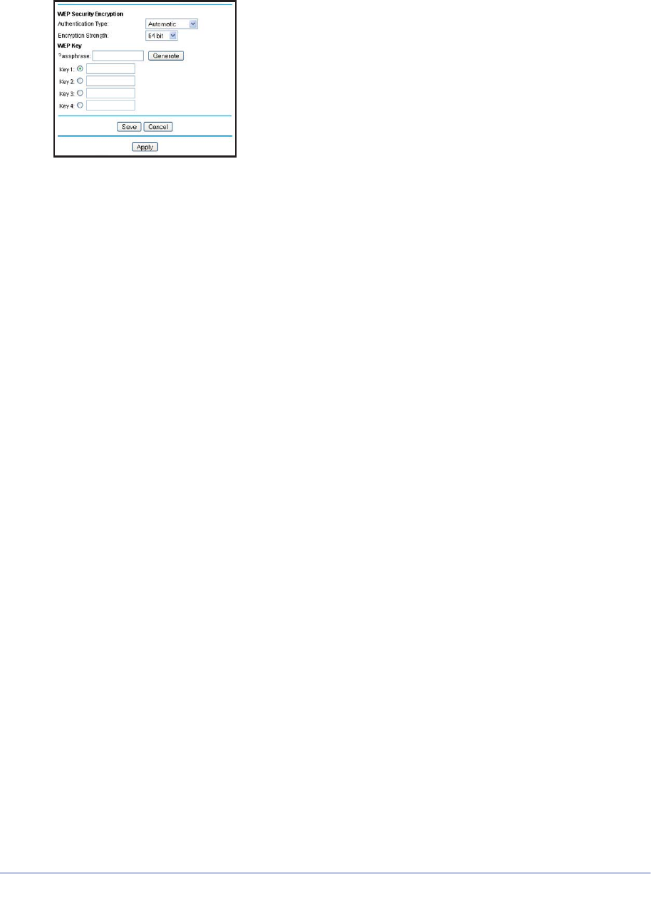
46 | Chapter 3. Wireless Settings
N600 Wireless Dual Band Gigabit ADSL2+ Modem Router DGND3700 User Manual
1. In the Security Options section, select WEP to display the following screen:
Figure 20. WEP Security Encryption section
2. Select the authentication type. The default is Automatic. Other choices are Open System
(any client can authenticate itself to the network) and Shared Key (a passphrase and a
four-way challenge is needed for authentication).
3. Select the encryption strength setting, either 64 bit or 128 bit.
4. Enter the four data encryption keys either manually or automatically. These values must be
identical on all computers and access points in your network.
•Automatic. Enter a word or group of printable characters in the Passphrase field and
click Generate. The four key fields are automatically populated with key values.
•Manual. The number of hexadecimal digits that you enter depends on the encryption
strength setting:
-For 64-bit WEP, enter 10 hexadecimal digits (any combination of 0–9, a–f, or
A–F).
-For 128-bit WEP, enter 26 hexadecimal digits (any combination of 0–9, a–f, or
A–F).
5. Select the radio button for the key you want to make active.
Make sure you understand how the WEP key settings are configured in your wireless
adapter. Wireless adapter configuration utilities such as the one in Windows XP allow one
key entry, which has to match the default key you set in the wireless modem router.
6. Click Save to save your settings or click Apply so your changes to take effect immediately.

Chapter 4. Security Settings | 47
4
4. Security Settings
Keeping unwanted content out of your network
This chapter explains how to use the basic firewall features of the wireless modem router to
prevent objectionable content from reaching the PCs and other devices connected to your
network.
This chapter contains the following sections:
•Keyword Blocking of HTTP Traffic
•Firewall Rules to Control Network Access
•Configure Services
•Set the Time Zone
•Schedule Firewall Services
•Enable Security Event Email Notification
•Log the Network Activity
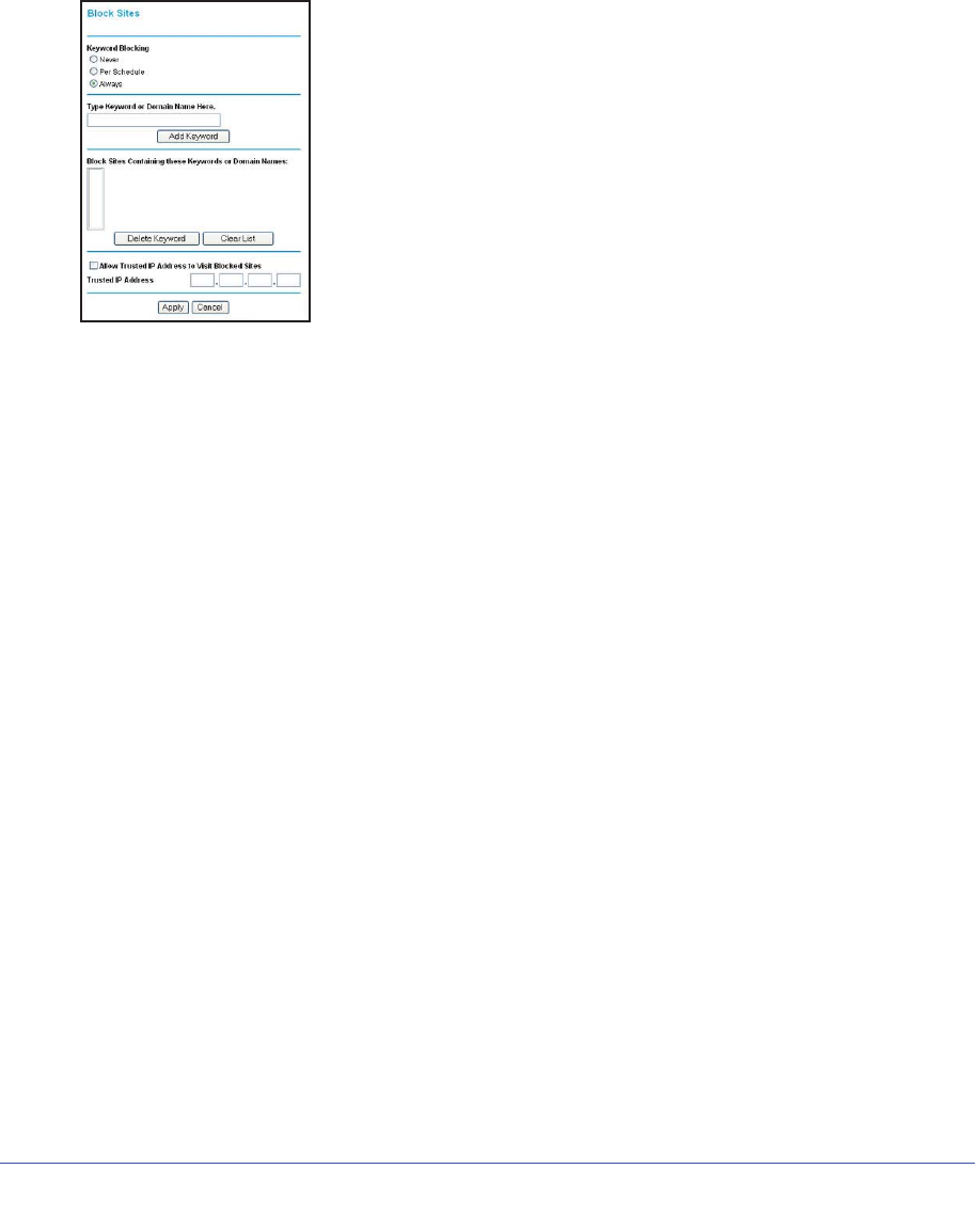
48 | Chapter 4. Security Settings
N600 Wireless Dual Band Gigabit ADSL2+ Modem Router DGND3700 User Manual
Keyword Blocking of HTTP Traffic
Use keyword blocking to prevent certain types of HTTP traffic from accessing your network.
The blocking can be always or according to a scheduled.
1. Select Content Filtering > Block Sites.
Figure 21. Block Sites screen
.
2. Select one of the keyword blocking options:
•Per Schedule. Turn on keyword blocking according to the Schedule screen settings.
•Always. Turn on keyword blocking all the time, independent of the Schedule screen.
3. In the Keyword field, enter a keyword or domain, click Add Keyword, and click Apply.
The Keyword list. supports up to 32 entries. Here are some sample entries:
•Specify XXX to block http://www.badstuff.com/xxx.html
•Specify .com if you want to allow only sites with domain suffixes such as .edu or .gov
•Enter a period (.) to block all Internet browsing access
Delete Keyword or Domain
1. Select the keyword you want to delete from the list.
2. Click Delete Keyword and click Apply to save your changes.
Specify Trusted Computer
You can exempt one trusted computer from blocking and logging. The computer you exempt
must have a fixed IP address.
1. In the Trusted IP Address field, enter the IP address.
2. Click Apply to save your changes.

Chapter 4. Security Settings | 49
N600 Wireless Dual Band Gigabit ADSL2+ Modem Router DGND3700 User Manual
Firewall Rules to Control Network Access
By default your router blocks any inbound traffic from the Internet to your computers except
for replies to your outbound traffic. You might need to create exceptions to this rule to allow
remove computers to access a server on your local network or to allow certain applications
and games to work correctly. Your router provides port forwarding and port triggering got
creating these exceptions.
This section covers the following topics:
•Remote Computer Access Basics
•Port Triggering to Open Incoming Ports
•Port Forwarding to Permit External Host Communications
•How Port Forwarding Differs from Port Triggering
•Configure Port Forwarding to Local Servers
•Configure Port Triggering
Remote Computer Access Basics
When a computer on your network needs to access a computer on the Internet, your
computer sends your router a message containing the source and destination address and
process information. Before forwarding your message to the remote computer, your router
has to modify the source information and create and track the communication session so that
replies can be routed back to your computer.
Here is an example of normal outbound traffic and the resulting inbound responses:
1. You open a browser and your operating system assigns port number 5678 to this
browser session.
2. You type http://www.example.com into the URL box and your computer creates a Web page
request message with the following address and port information. The request message is
sent to your router.
Source address. Your computer’s IP address.
Source port number. 5678, which is the browser session.
Destination address. The IP address of www.example.com, which your computer finds
by asking a DNS server.
Destination port number. 80, which is the standard port number for a Web server
process.
3. Your router creates an entry in its internal session table describing this communication
session between your computer and the Web server at www.example.com. Before sending
the Web page request message to www.example.com, your router stores the original
information and then modifies the source information in the request message, performing
Network Address Translation (NAT):

50 | Chapter 4. Security Settings
N600 Wireless Dual Band Gigabit ADSL2+ Modem Router DGND3700 User Manual
•The source address is replaced with your router’s public IP address. This is
necessary because your computer uses a private IP address that is not globally
unique and cannot be used on the Internet.
•The source port number is changed to a number chosen by the router, such as 33333.
This is necessary because two computers could independently be using the same
session number.
Your router then sends this request message through the Internet to the Web server at
www.example.com.
4. The Web server at www.example.com composes a return message with the requested Web
page data. The return message contains the following address and port information. The
Web server then sends this reply message to your router.
Source address. The IP address of www.example.com.
Source port number. 80, which is the standard port number for a Web server process.
Destination address. The public IP address of your router.
Destination port number. 33333.
5. Upon receiving the incoming message, your router checks its session table to determine
whether there is an active session for port number 33333. Finding an active session, the
router then modifies the message to restore the original address information replaced by
NAT. Your router sends this reply message to your computer, which displays the Web
page from www.example.com. The message now contains the following address and port
information.
Source address. The IP address of www.example.com.
Source port number. 80, which is the standard port number for a Web server process.
Destination address. Your computer’s IP address.
Destination port number. 5678, which is the browser session that made the initial
request.
6. When you finish your browser session, your router eventually detects a period of inactivity in
the communications. Your router then removes the session information from its session table
and incoming traffic is no longer accepted on port number 33333.
Port Triggering to Open Incoming Ports
In the preceding example, requests are sent to a remote computer by your router from a
particular service port number, and replies from the remote computer to your router are
directed to that port number. If the remote server sends a reply back to a different port
number, your router does not recognize it and discards it. However, some application servers
(such as FTP and IRC servers) send replies back to multiple port numbers. Using the port
triggering function of your router, you can tell the router to open additional incoming ports
when a particular outgoing port originates a session.
An example is Internet Relay Chat (IRC). Your computer connects to an IRC server at
destination port 6667. The IRC server not only responds to your originating source port, but

Chapter 4. Security Settings | 51
N600 Wireless Dual Band Gigabit ADSL2+ Modem Router DGND3700 User Manual
also sends an “identify” message to your computer on port 113. Using port triggering, you can
tell the router, “When you initiate a session with destination port 6667, you have to also allow
incoming traffic on port 113 to reach the originating computer.” Using steps similar to the
preceding example, the following sequence shows the effects of the port triggering rule you
have defined:
1. You open an IRC client program to start a chat session on your computer.
2. Your IRC client composes a request message to an IRC server using a destination port
number of 6667, the standard port number for an IRC server process. Your computer then
sends this request message to your router.
3. Your router creates an entry in its internal session table describing this communication
session between your computer and the IRC server. Your router stores the original
information, performs Network Address Translation (NAT) on the source address and port,
and sends this request message through the Internet to the IRC server.
4. Noting your port triggering rule and having observed the destination port number of 6667,
your router creates an additional session entry to send any incoming port 113 traffic to your
computer.
5. The IRC server sends a return message to your router using the NAT-assigned source port
(as in the previous example, let’s say port 33333) as the destination port. The IRC server
also sends an “identify” message to your router with destination port 113.
6. Upon receiving the incoming message to destination port 33333, your router checks its
session table to determine whether there is an active session for port number 33333.
Finding an active session, the router restores the original address information replaced by
NAT and sends this reply message to your computer.
7. Upon receiving the incoming message to destination port 113, your router checks its session
table and learns that there is an active session for port 113, associated with your computer.
The router replaces the message’s destination IP address with your computer’s IP address
and forwards the message to your computer.
8. When you finish your chat session, your router eventually senses a period of inactivity in the
communications. The router then removes the session information from its session table,
and incoming traffic is no longer accepted on port numbers 33333 or 113.
To configure port triggering, you need to know which inbound ports the application needs.
Also, you need to know the number of the outbound port that will trigger the opening of the
inbound ports. You can usually determine this information by contacting the publisher of the
application, or user groups or newsgroups.
Note: Only one computer at a time can use the triggered application.
Port Forwarding to Permit External Host Communications
In both of the preceding examples, your computer initiates an application session with a
server computer on the Internet. However, you might need to allow a client computer on the
Internet to initiate a connection to a server computer on your network. Normally, your router
ignores any inbound traffic that is not a response to your own outbound traffic. You can
configure exceptions to this default rule by using the port forwarding feature.

52 | Chapter 4. Security Settings
N600 Wireless Dual Band Gigabit ADSL2+ Modem Router DGND3700 User Manual
A typical application of port forwarding can be shown by reversing the client-server
relationship from our previous Web server example. In this case, a remote computer’s
browser needs to access a Web server running on a computer in your local network. Using
port forwarding, you can tell the router, “When you receive incoming traffic on port 80 (the
standard port number for a Web server process), forward it to the local computer at
192.168.1.123.” The following sequence shows the effects of the port forwarding rule you
have defined:
1. The user of a remote computer opens a browser and requests a Web page from
www.example.com, which resolves to the public IP address of your router. The remote
computer composes a Web page request message with the following destination
information:
Destination address. The IP address of www.example.com, which is the address of your
router.
Destination port number. 80, which is the standard port number for a Web server
process.
The remote computer then sends this request message through the Internet to your
router.
2. Your router receives the request message and looks in its rules table for any rules covering
the disposition of incoming port 80 traffic. Your port forwarding rule specifies that incoming
port 80 traffic should be forwarded to local IP address 192.168.1.123. Therefore, your router
modifies the destination information in the request message:
The destination address is replaced with 192.168.1.123.
Your router then sends this request message to your local network.
3. Your Web server at 192.168.1.123 receives the request and composes a return message
with the requested Web page data. Your Web server then sends this reply message to your
router.
4. Your router performs Network Address Translation (NAT) on the source IP address, and
sends this request message through the Internet to the remote computer, which displays the
Web page from www.example.com.
To configure port forwarding, you need to know which inbound ports the application needs.
You usually can determine this information by contacting the publisher of the application or
the relevant user groups and newsgroups.
How Port Forwarding Differs from Port Triggering
The following points summarize the differences between port forwarding and port triggering:
•Port triggering can be used by any computer on your network, although only one
computer can use it at a time.
•Port forwarding is configured for a single computer on your network.
•Port triggering does not need to know the computer’s IP address in advance. The IP
address is captured automatically.
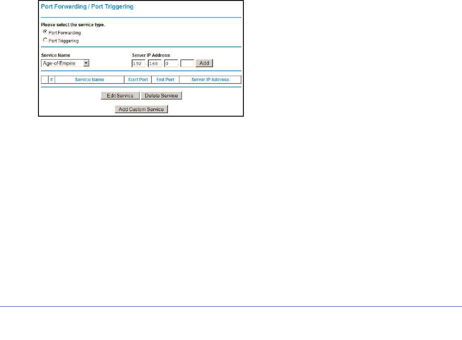
Chapter 4. Security Settings | 53
N600 Wireless Dual Band Gigabit ADSL2+ Modem Router DGND3700 User Manual
•Port forwarding requires that you specify the computer’s IP address during configuration,
and the IP address can never change.
•Port triggering requires specific outbound traffic to open the inbound ports, and the
triggered ports are closed after a period of no activity.
•Port forwarding is always active and does not need to be triggered.
Configure Port Forwarding to Local Servers
Using the port forwarding feature, you can allow certain types of incoming traffic to reach
servers on your local network. For example, you might want to make a local Web server, FTP
server, or game server visible and available to the Internet.
Use the Port Forwarding screen to configure the router to forward specific incoming protocols
to computers on your local network. In addition to servers for specific applications, you can
also specify a default DMZ server to which all other incoming protocols are forwarded.
Before starting, you need to determine which type of service, application, or game you want
to provide, and the local IP address of the computer that will provide the service. The server
computer has to always have the same IP address.
Tip: To ensure that your server computer always has the same IP address,
use the reserved IP address feature of your product.
1. Select Content Filtering > Port Forwarding/Port Triggering to display the following
screen:
Figure 22. Setting up port forwarding
2. Select the Port Forwarding radio button as the Service type.
3. From the Service Name list, select the service or game that you will host on your network. If
the service does not appear in the list, see Add a Custom Service on page 53.
4. In the corresponding Server IP Address box, enter the last digit of the IP address of your
local computer that will provide this service.
5. Click Add. The service appears in the list in the screen.
Add a Custom Service
To define a service, game, or application that does not appear in the Service Name list, you
have to first determine which port number or range of numbers is used by the application.
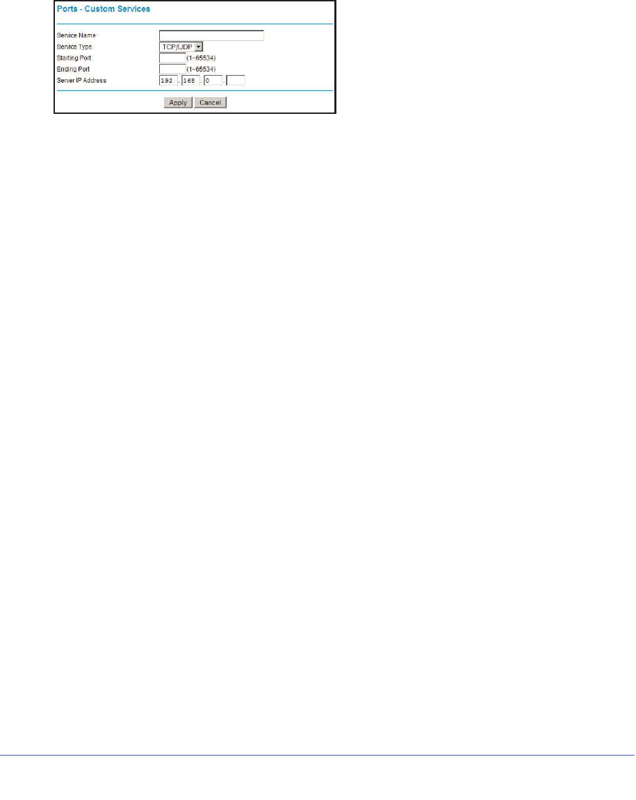
54 | Chapter 4. Security Settings
N600 Wireless Dual Band Gigabit ADSL2+ Modem Router DGND3700 User Manual
You can usually determine this information by contacting the publisher of the application or
user groups or newsgroups. When you have the port number information, follow these steps:
1. Select Content Filtering > Port Forwarding/Port Triggering.
2. Select the Port Forwarding radio button as the Service type.
3. Click the Add Custom Service button to display the following screen:
Figure 23. Set up custom services
4. In the Service Name field, enter a descriptive name.
5. In the Protocol field, select the protocol. If you are unsure, select TCP/UDP.
6. In the Starting Port field, enter the beginning port number.
•If the application uses a single port, enter the same port number in the Ending Port
field.
•If the application uses a range of ports, enter the ending port number of the range in
the Ending Port field.
7. In the Server IP Address field, enter the IP address of your local computer that will provide
this service.
8. Click Apply. The service appears in the list in the Port Forwarding/Port Triggering screen.
Editing or Deleting a Port Forwarding Entry
To edit or delete a port forwarding entry:
1. In the table, click the button next to the service name.
2. Click Edit Service or Delete Service.
Application Example: Making a Local Web Server Public
If you host a Web server on your local network, you can use port forwarding to allow Web
requests from anyone on the Internet to reach your Web server.
To make a local Web server public:
1. Assign your Web server either a fixed IP address or a dynamic IP address using DHCP
address reservation. In this example, your router will always give your Web server an IP
address of 192.168.1.33.
2. In the Port Forwarding screen, configure the router to forward the HTTP service to the local
address of your Web server at 192.168.1.33. HTTP (port 80) is the standard protocol for
Web servers.

Chapter 4. Security Settings | 55
N600 Wireless Dual Band Gigabit ADSL2+ Modem Router DGND3700 User Manual
3. (Optional) Register a host name with a Dynamic DNS service, and configure your router to
use the name. To access your Web server from the Internet, a remote user has to know the
IP address that has been assigned by your ISP. However, if you use a Dynamic DNS
service, the remote user can reach your server by a user-friendly Internet name, such as
mynetgear.dyndns.org.
Configure Port Triggering
Port triggering is a dynamic extension of port forwarding that is useful in these cases:
•More than one local computer needs port forwarding for the same application (but not
simultaneously).
•An application needs to open incoming ports that are different from the outgoing port.
When port triggering is enabled, the router monitors outbound traffic looking for a specified
outbound “trigger” port. When the router detects outbound traffic on that port, it remembers
the IP address of the local computer that sent the data. The router then temporarily opens the
specified incoming port or ports, and forwards incoming traffic on the triggered ports to the
triggering computer.
While port forwarding creates a static mapping of a port number or range to a single local
computer, port triggering can dynamically open ports to any computer that needs them and
can close the ports when they are no longer needed.
Note: If you use applications such as multiplayer gaming, peer-to-peer
connections, real-time communications such as instant messaging,
or remote assistance (a feature in Windows XP), you should also
enable Universal Plug and Play (UPnP).
To configure port triggering, you need to know which inbound ports the application needs.
Also, you need to know the number of the outbound port that will trigger the opening of the
inbound ports. You can usually determine this information by contacting the publisher of the
application or user groups or newsgroups.
To set up port triggering:
1. Select Content Filtering > Port Forwarding/Port Triggering to display the following
screen:
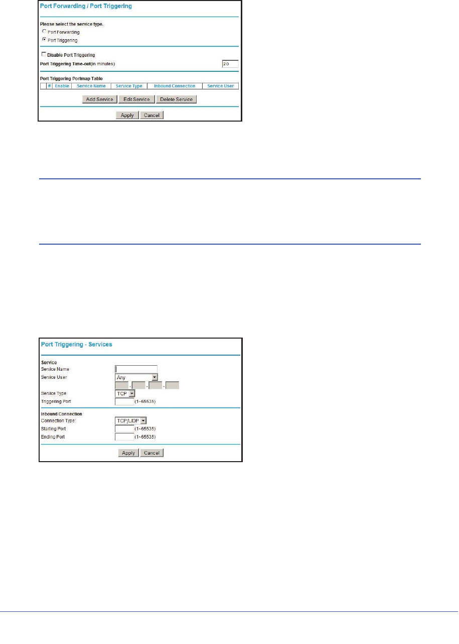
56 | Chapter 4. Security Settings
N600 Wireless Dual Band Gigabit ADSL2+ Modem Router DGND3700 User Manual
2. Select the Port Triggering radio button to display the port triggering information.
Figure 24. Set up port triggering
3. Deselect the Disable Port Triggering check box.
Note: If the Disable Port Triggering check box is selected after you
configure port triggering, port triggering is disabled. However, any
port triggering configuration information you added to the router is
retained even though it is not used.
4. In the Port Triggering Timeout field, enter a value up to 9999 minutes. This value controls
the inactivity timer for the designated inbound ports. The inbound ports close when the
inactivity time expires. This is required because the router cannot be sure when the
application has terminated.
5. Click Add Service.
Figure 25. Add a service for port triggering
6. In the Service Name field, type a descriptive service name.
7. In the Service User field, select Any (the default) to allow this service to be used by any
computer on the Internet. Otherwise, select Single address, and enter the IP address of
one computer to restrict the service to a particular computer.
8. Select the service type, either TCP or UDP or both (TCP/UDP). If you are not sure, select
TCP/UDP.
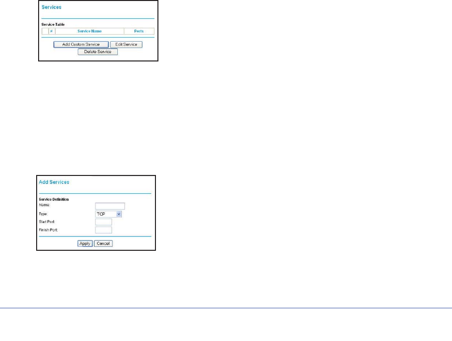
Chapter 4. Security Settings | 57
N600 Wireless Dual Band Gigabit ADSL2+ Modem Router DGND3700 User Manual
9. In the Triggering Port field, enter the number of the outbound traffic port that will cause the
inbound ports to be opened.
10. Enter the inbound connection port information in the Connection Type,Starting Port, and
Ending Port fields.
11. Click Apply. The service appears in the Port Triggering Portmap table.
Configure Services
Services are functions performed by server computers at the request of client computers. For
example, Web servers serve Web pages, time servers serve time and date information, and
game hosts serve data about other players’ moves. When a computer on the Internet sends
a request for service to a server computer, the requested service is identified by a service or
port number. This number appears as the destination port number in the transmitted IP
packets. For example, a packet that is sent with destination port number 80 is an HTTP (Web
server) request.
The service numbers for many common protocols are defined by the Internet Engineering
Task Force (IETF at http://www.ietf.org/) and published in RFC1700, “Assigned Numbers.”
Service numbers for other applications are typically chosen from the range 1024 to 65535 by
the authors of the application. Although the wireless modem router already holds a list of
many service port numbers, you are not limited to these choices.
To create your own service definitions:
1. Select Content Filtering > Services to display the following screen:
Figure 26. Services screen
•To create a new service, click the Add Custom Service button to display the Add
Services screen.
•To edit a service, select its button on the left side of the table, and click Edit Service.
•To delete a service, select its button on the left side of the table, and click Delete
Service.
2. Use the following screen to define or edit a service.
Figure 27. Add Services screen
•Name. Enter a meaningful name for the service.
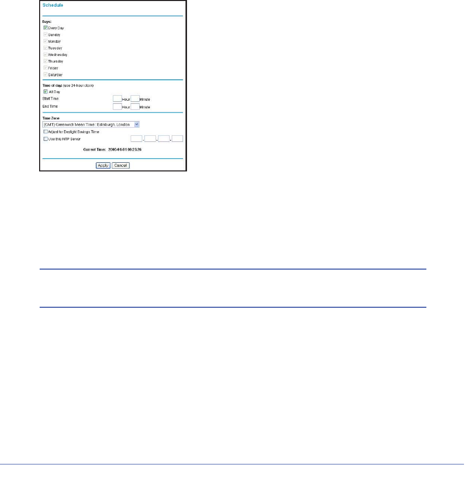
58 | Chapter 4. Security Settings
N600 Wireless Dual Band Gigabit ADSL2+ Modem Router DGND3700 User Manual
•Type. Select the correct type for this service. If in doubt, select TCP/UDP. The options
are TCP, UDP, TCP/UDP.
•Start Port and End Port. If a port range is required, enter the range here. If a single
port is required, enter the same value in both fields.
3. Click Apply to save your changes.
Set the Time Zone
The wireless modem router uses the Network Time Protocol (NTP) to obtain the current time
and date from one of several network time servers on the Internet.
1. Select Content Filtering > Schedule to display the following screen:
Figure 28. Schedule screen
2. Select your time zone. This setting determines the blocking schedule and time-stamping of
log entries.
3. If your time zone is in daylight savings time, select the Adjust for Daylight Savings Time
check box to add one hour to standard time.
Note: If your region uses daylight savings time, select Adjust for Daylight
Savings Time on the first day and clear it after the last day.
4. The wireless modem router has a list of NETGEAR NTP servers. If you would prefer to use
a particular NTP server as the primary server, select the Use this NTP Server check box,
and enter its IP address.
5. Click Apply to save your settings.
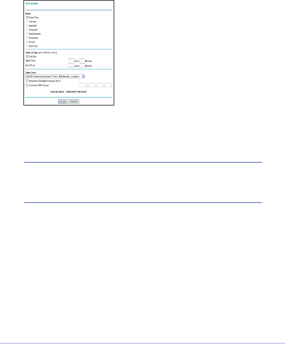
Chapter 4. Security Settings | 59
N600 Wireless Dual Band Gigabit ADSL2+ Modem Router DGND3700 User Manual
Schedule Firewall Services
If you enabled services blocking in the Block Services screen or port forwarding in the Ports
screen, you can set up a schedule for when blocking occurs or when access is not restricted.
1. Select Content Filtering > Schedule to display the following screen:
Figure 29. Schedule screen
2. To block Internet services based on a schedule, select Every Day or select one or more
days. If you want to limit access completely for the selected days, select All Day. Otherwise,
to limit access during certain times for the selected days, enter times in the Start Time and
End Time fields.
Note: Enter the values in 24-hour time format. For example, 10:30 a.m.
would be 10 hours and 30 minutes, and 10:30 p.m. would be 22
hours and 30 minutes. If you set the start time after the end time, the
schedule is effective through midnight the next day.
3. Click Apply to save your settings.
Enable Security Event Email Notification
To receive logs and alerts by email, provide your email information in the E-mail screen and
specify which alerts you want to receive and how often.
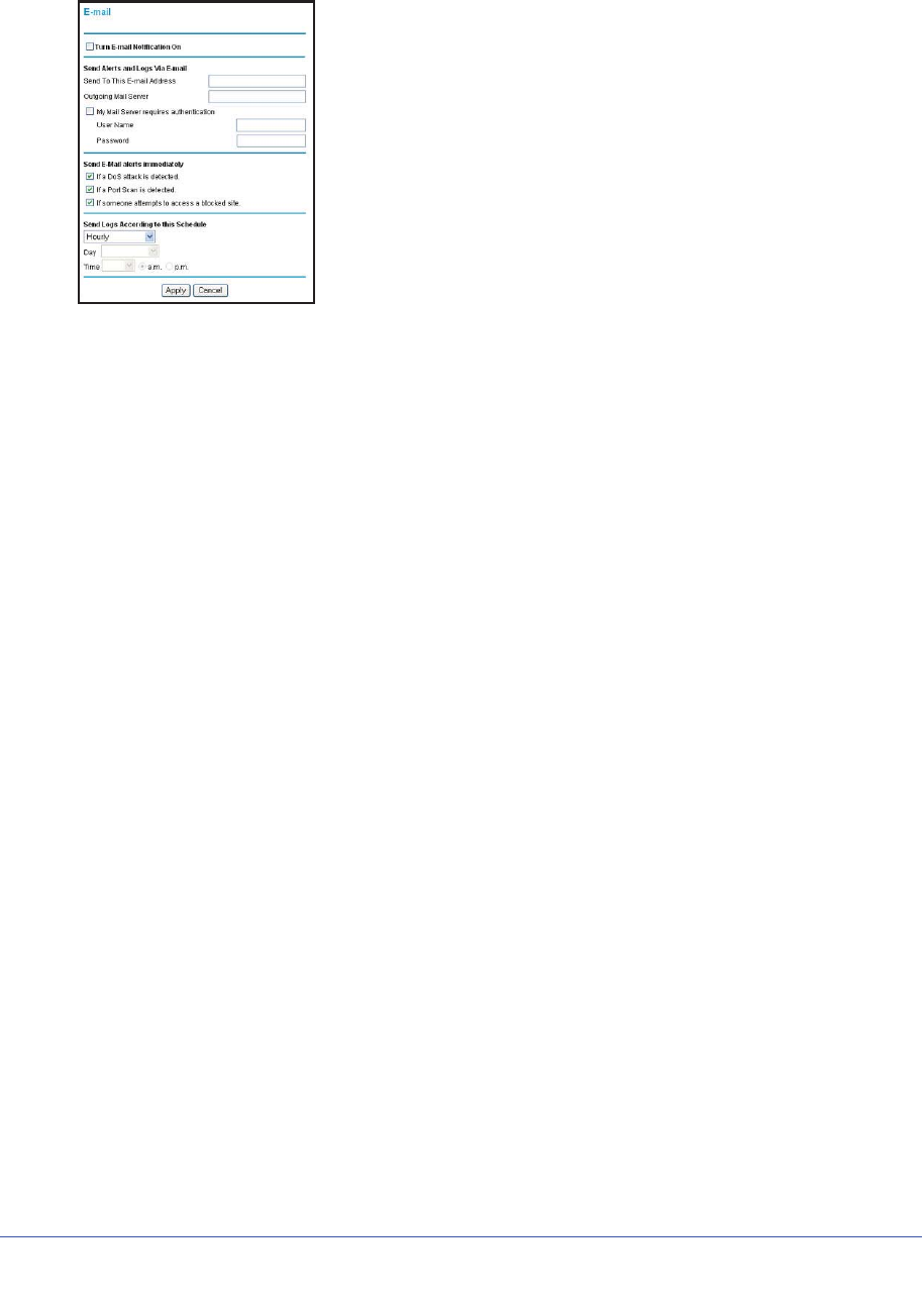
60 | Chapter 4. Security Settings
N600 Wireless Dual Band Gigabit ADSL2+ Modem Router DGND3700 User Manual
1. Select Content Filtering > E-mail to display the following screen:
Figure 30. E-Mail screen
•Turn E-mail Notification On. Select this check box if you want to receive email logs and
alerts from the wireless modem router.
•Send To This E-mail Address. Enter the email address where you want logs and alerts
sent. This email address is also used as the From address. If you leave this field blank,
log and alert messages are not sent by email.
•Outgoing Mail Server. Enter the name or IP address of your ISP’s outgoing (SMTP) mail
server (such as mail.myISP.com). You might be able to find this information in the
configuration settings of your email program. Enter the email address to which logs and
alerts are sent. This email address is also used as the From address. If you leave this
field blank, log and alert messages are not sent by e-mail.
•My Mail Server requires authentication. If you use an outgoing mail server provided by
your current ISP, you do not need to select this field. If you use an email account that is
not provided by your ISP, select this field, and enter the required user name and
password information.
•Send E-Mail alerts immediately. Select the corresponding check box if you would like
immediate notification of a significant security event, such as a known attack, port scan,
or attempted access to a blocked site.
•Send Logs According to this Schedule. Specifies how often to send the logs: Hourly,
Daily, Weekly, or When Full.
-Day for sending logs specifies which day of the week to send the log. This is relevant
when the log is sent weekly.
-Time for sending log specifies the time of day to send the log. This is relevant when
the log is sent daily or weekly.
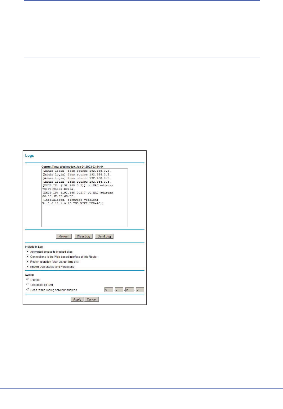
Chapter 4. Security Settings | 61
N600 Wireless Dual Band Gigabit ADSL2+ Modem Router DGND3700 User Manual
Note: If the Weekly, Daily, or Hourly option is selected and the log fills up
before the specified period, the log is automatically emailed to the
specified email address. After the log is sent, it is cleared from the
wireless modem router’s memory. If the wireless modem router
cannot email the log file, the log buffer might fill up. In this case, the
wireless modem router overwrites the log and discards its contents.
Log the Network Activity
A log is a detailed record of the websites that users on your network have accessed or
attempted to access. If you have set up content filtering on the Block Sites screen, the Logs
screen shows you when someone on your network tried to access a blocked site. If you have
e-mail notification on, you will receive these logs in an e-mail message. If you do not have
e-mail notification set up, you can view the logs on the Logs screen.
1. Select Content Filtering > Logs to display the Logs screen:
Figure 31. Logs screen
a. Click Clear Log to delete all the log entries.
b. Click Refresh to see the most recent access attempts.
c. Click Send Log to send the log file to your e-mail account. This feature is useful for
testing your e-mail settings.

62 | Chapter 4. Security Settings
N600 Wireless Dual Band Gigabit ADSL2+ Modem Router DGND3700 User Manual
2. Include in Log—Use these checkboxes to determine which events are included in the log.
Checking all options will increase the size of the log, so it is good practice to disable any
events that are not really required.
•Attempted access to blocked sites. If checked, attempted Internet accesses that
were blocked are logged.
•Connections to the Web-based interface of this Router. If checked, connections
are logged to this Router, rather than through this Router to the Internet.
•Router operation. If checked, router operations not covered by the selections above
are logged.
•Known DoS attacks and Port Scans. If checked, denial of service attacks, as well
as port scans, are logged.
3. Syslog—The Logs can be sent to a Syslog server. Enable one of these three options, as
required:
•Disable. Select this if you don't have a Syslog server.
•Broadcast on LAN. The syslog data is broadcast rather than sent to a specific
Syslog server. Use this if your Syslog server does not have a fixed IP address.
•Send to this Syslog server IP address. If your Syslog server has a fixed IP address,
select this option, and enter the IP address of your Syslog server.
4. Click Apply to save your changes.

Chapter 5. Network Maintenance | 63
5
5. Network Maintenance
Administering your network
This chapter describes the wireless modem router settings for administering and maintaining the
router and home network.
Note: For security reasons, the wireless modem router has its own user
name and password that default to admin and password. You can
and should update your password regularly. See Change Password
and Login Time-Out on page 32.
This chapter contains the following sections:
•Upgrade the Router Firmware
•Manually Check for Firmware Upgrades
•Manage Configuration File
•View Router Status
•View Attached Devices
•Run Diagnostic Utilities
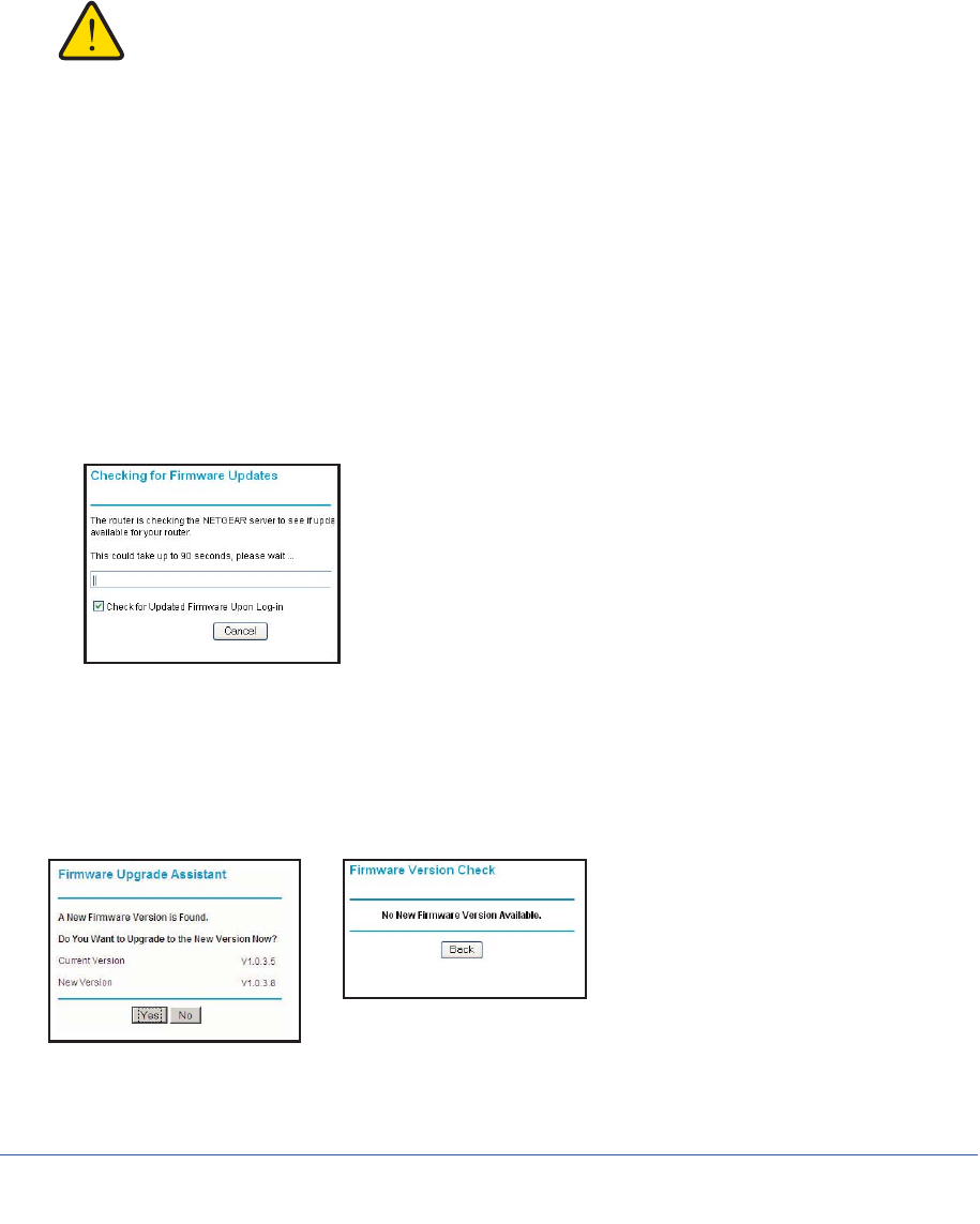
64 | Chapter 5. Network Maintenance
N600 Wireless Dual Band Gigabit ADSL2+ Modem Router DGND3700 User Manual
Upgrade the Router Firmware
The wireless modem router firmware (routing software) is stored in flash memory. By default,
when you log in to your wireless modem router, it checks the NETGEAR website for new
firmware and alerts you if there is a newer version.
WARNING!
When uploading firmware to the wireless modem router, do not
interrupt the Web browser by closing the window, clicking a link,
or loading a new page. If the browser is interrupted, it could
corrupt the firmware.
Automatic Firmware Checking Off
You can turn the automatic firmware checking off and check for firmware updates manually if
you prefer. See Manually Check for Firmware Upgrades on page 65. To turn off the automatic
firmware check at log in:
1. Select Maintenance > Router Upgrade.
2. Uncheck the Check for Updated Firmware Upon Log-in check box at the bottom of this
screen:.
Figure 32. Checking for Firmware Updates screen
Automatic Firmware Checking On
When automatic firmware checking is on, the wireless modem router performs the check and
notifies you if an upgrade is available or not as shown here.
Figure 33. Firmware check notification screens
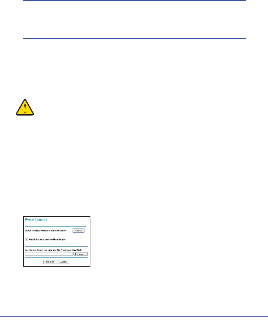
Chapter 5. Network Maintenance | 65
N600 Wireless Dual Band Gigabit ADSL2+ Modem Router DGND3700 User Manual
1. Click Yes to allow the wireless modem router to download and install the new firmware.
The upgrade process could take a few minutes. When the upload is complete, your
wireless modem router restarts.
2. Go to the DGND3700 support page at http://www.netgear.com/support. and read the new
firmware release notes to determine whether you need to reconfigure the modem router
after upgrading.
Note: If you get a “Firmware needs to be reloaded” message, it means a
problem has been detected with the router’s firmware. Follow the
prompts to correct the problem or see Firmware Needs to Be
Reloaded on page 151 for a description of the steps.
Manually Check for Firmware Upgrades
You can use the Router Upgrade screen to manually check the NETGEAR website for newer
versions of firmware for your product.
WARNING!
When uploading firmware to the wireless modem router, do not
interrupt the Web browser by closing the window, clicking a link,
or loading a new page. If the browser is interrupted, it could
corrupt the firmware.
1. Select Maintenance > Router Status and make a note of the wireless modem router
firmware version number.
2. Go to the DGND3700 support page on the NETGEAR website at
http://www.netgear.com/support.
3. If the firmware version on the NETGEAR website is newer than the firmware on your
wireless modem router, download the file to your computer.
4. Select Maintenance > Router Upgrade to display the following screen:
Figure 34. Router Upgrade screen
5. Click Browse, and locate the firmware you downloaded (the file ends in .img).
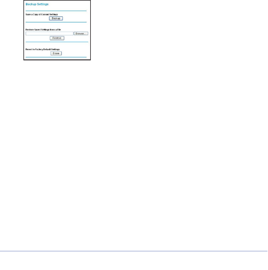
66 | Chapter 5. Network Maintenance
N600 Wireless Dual Band Gigabit ADSL2+ Modem Router DGND3700 User Manual
6. Click Upload to send the firmware to the wireless modem router.
When the upload completes, your wireless modem router restarts. The upgrade process
typically takes about one minute. Read the new firmware release notes to determine
whether or not you need to reconfigure the wireless modem router after upgrading.
Manage Configuration File
The router configuration settings are stored in a configuration file (*.cfg). This file can be
backed up to your computer, restored, or reverted to factory default settings.
Back Up
1. Select Maintenance > Backup Settings to display the following screen:
Figure 35. Backup Settings screen
2. Click Backup to save a copy of the current settings.
3. Choose a location to store the .cfg file that is on a computer on your network.
Restore
1. Enter the full path to the file on your network, or click the Browse button to find the file.
2. When you have located the .cfg file, click the Restore button to upload the file to the
wireless modem router.
Upon completion, the wireless modem router reboots.
Erase
Click the Erase button to reset the wireless modem router to its factory default settings.
Alternately, press the Wireless On/Off and WPS buttons on the side panel of the wireless
modem router simultaneously for 6 seconds.
Erase sets the password to password, the LAN IP address to 192.168.0.1, and enables the
wireless modem router’s DHCP.
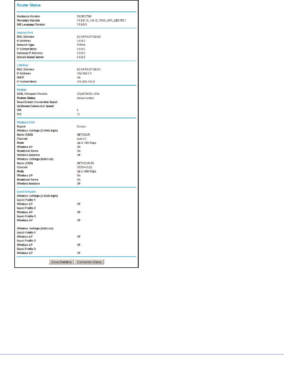
Chapter 5. Network Maintenance | 67
N600 Wireless Dual Band Gigabit ADSL2+ Modem Router DGND3700 User Manual
View Router Status
Select Maintenance > Router Status to display the following screen. The Router Status
screen provides the status and usage information described in the following figure.
Figure 36. Router Status screen
Use the Router Status page to check the current settings and statistics for your router. This
page shows you the current settings. If something needs to be changed, you'll have to
change it on the relevant page.
Account Name: This is the Account Name that you entered in the Setup Wizard or Basic
Settings.

68 | Chapter 5. Network Maintenance
N600 Wireless Dual Band Gigabit ADSL2+ Modem Router DGND3700 User Manual
Firmware Version: This is the current software the router is using. This will change if you
upgrade your router.
Internet Port: These are the current settings that you set in the Setup Wizard or Basic
Settings pages.
•MAC Address. the physical address of the router, as seen from the Internet.
•IP Address. current Internet IP address. If assigned dynamically, and no Internet
connection exists, this will be blank or 0.0.0.0.
•Network Type. indicates either Client (IP address is obtained dynamically) or None.
•IP Subnet Mask. the subnet mask associated with the Internet IP address
•Domain Name Server. displays the address of the current DNS.
LAN Port: These are the current settings, as set in the LAN IP Setup page.
•MAC Address. the physical address of the router, as seen from the local LAN.
•IP Address. LAN IP address of the router.
•DHCP. indicates if the router is acting as a DHCP server for devices on your LAN.
•IP Subnet Mask. subnet mask associated with the LAN IP address.
Modem: The current Modem status and settings are shown in this section.
•ADSL Firmware Version. This is the version number of the low-level ADSL firmware.
This is contained within the router firmware.
•Modem Status. the current state of the ADSL connection to your phone company.
•DownStream Connection Speed. the connection speed of the ADSL connection from
the phone company to your Router.
•UpStream Connection Speed. the connection speed of the ADSL connection from your
router to the phone company.
•VPI. the VPI setting entered on the ADSL Settings page.
•VCI. the VCI setting entered on the ADSL Settings page.
Wireless Port: These are the current settings, as set in the Wireless Settings page.
•Name (SSID). SSID of the router.
•Region. the location (country).
•Channel. the current channel in use.
•Wireless AP. indicates if the access point feature of the router is enabled or not. If not
enabled, the Wireless LED on the front panel will be off.
•Broadcast Name. indicates if the router is broadcasting its SSID.
Click Show Statistics to see router performance statistics such as the number of packets
sent and number of packets received for each port.
Click Connection Status to see information about your current connection.
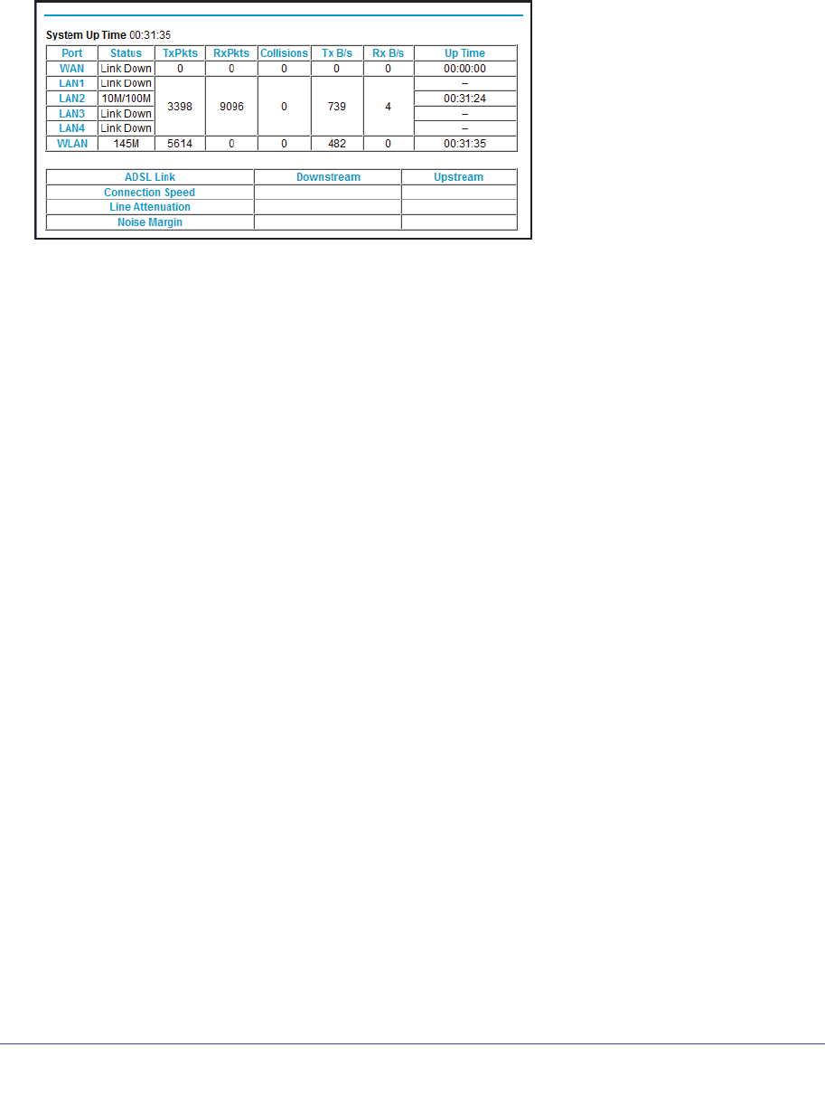
Chapter 5. Network Maintenance | 69
N600 Wireless Dual Band Gigabit ADSL2+ Modem Router DGND3700 User Manual
Show Statistics Button
Click the Show Statistics button on the Router Status screen to display a screen similar to
this:
Figure 37. Router statistics screen
Port
The statistics for the WAN (Internet), LAN (local), and wireless LAN (WLAN) ports. For each
port, the screen displays the following:
Status. The link status of the port.
TxPkts. The number of packets transmitted since reset or manual clear.
RxPkts. The number of packets received since reset or manual clear.
Collisions. The number of collisions since reset or manual clear.
Tx B/s. The current line utilization—percentage of current bandwidth used.
Rx B/s. The average line utilization.
Up Time. The time elapsed since the last power cycle or reset.
ADSL Link Downstream or Upstream
The statistics for the upstream and downstream ADSL link. These statistics are of interest to
your technical support representative if you have problems obtaining or maintaining a
connection.
Connection Speed
Typically, the downstream speed is faster than the upstream speed.
Line Attenuation
The line attenuation increases the farther you are physically located from your ISP’s facilities.
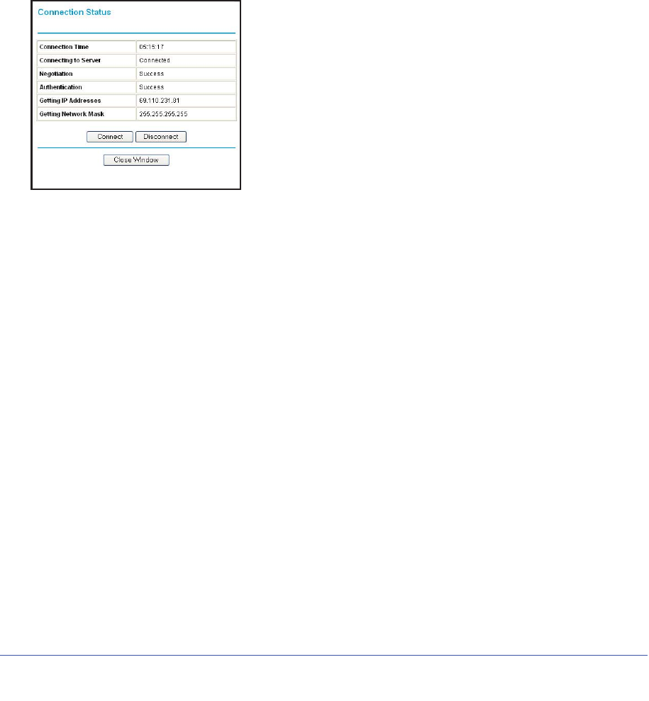
70 | Chapter 5. Network Maintenance
N600 Wireless Dual Band Gigabit ADSL2+ Modem Router DGND3700 User Manual
Noise Margin
The signal-to-noise ratio, which is a measure of the quality of the signal on the line.
Poll Interval
The interval at which the statistics are updated in this window. Click the Stop button to freeze
the display.
Connection Status Button
In the Router Status screen, click the Connection Status button to display a screen similar to
this:
Figure 38. Connection Status screen
Connection Time. The time elapsed since the last connection to the Internet through the
ADSL port.
Connecting to sender. The connection status.
Negotiation. Success or Failed.
Authentication. Success or Failed.
Obtaining IP Address. The IP address assigned to the WAN port by the ISP.
Obtaining Network Mask. The network mask assigned to the WAN port by the ISP.
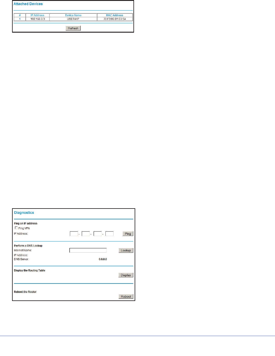
Chapter 5. Network Maintenance | 71
N600 Wireless Dual Band Gigabit ADSL2+ Modem Router DGND3700 User Manual
View Attached Devices
The Attached Devices screen presents a table of all IP devices that the wireless modem
router has discovered on the local network. Select Maintenance > Attached Devices to view
the following table:
Figure 39. Attached Devices screen
For each device, the table shows the IP address, device name if available, and the Ethernet
MAC address. Note that if the wireless modem router is rebooted, the table data is lost until
the wireless modem router rediscovers the devices. To force the wireless modem router to
look for attached devices, click the Refresh button.
Run Diagnostic Utilities
The wireless modem router has a diagnostics feature that you can use to perform the
following functions:
•Ping an IP address to test connectivity to see if you can reach a remote host.
•Perform a DNS lookup to test if an Internet name resolves to an IP address to verify that
the DNS server configuration is working.
•Display the Routing table to identify what other wireless modem routers the wireless
modem router is communicating with.
•Reboot the wireless modem router to enable new network configurations to take effect or
to clear problems with the wireless modem router’s network connection.
Select Maintenance > Diagnostics to display the following screen.
Figure 40. Diagnostics screen
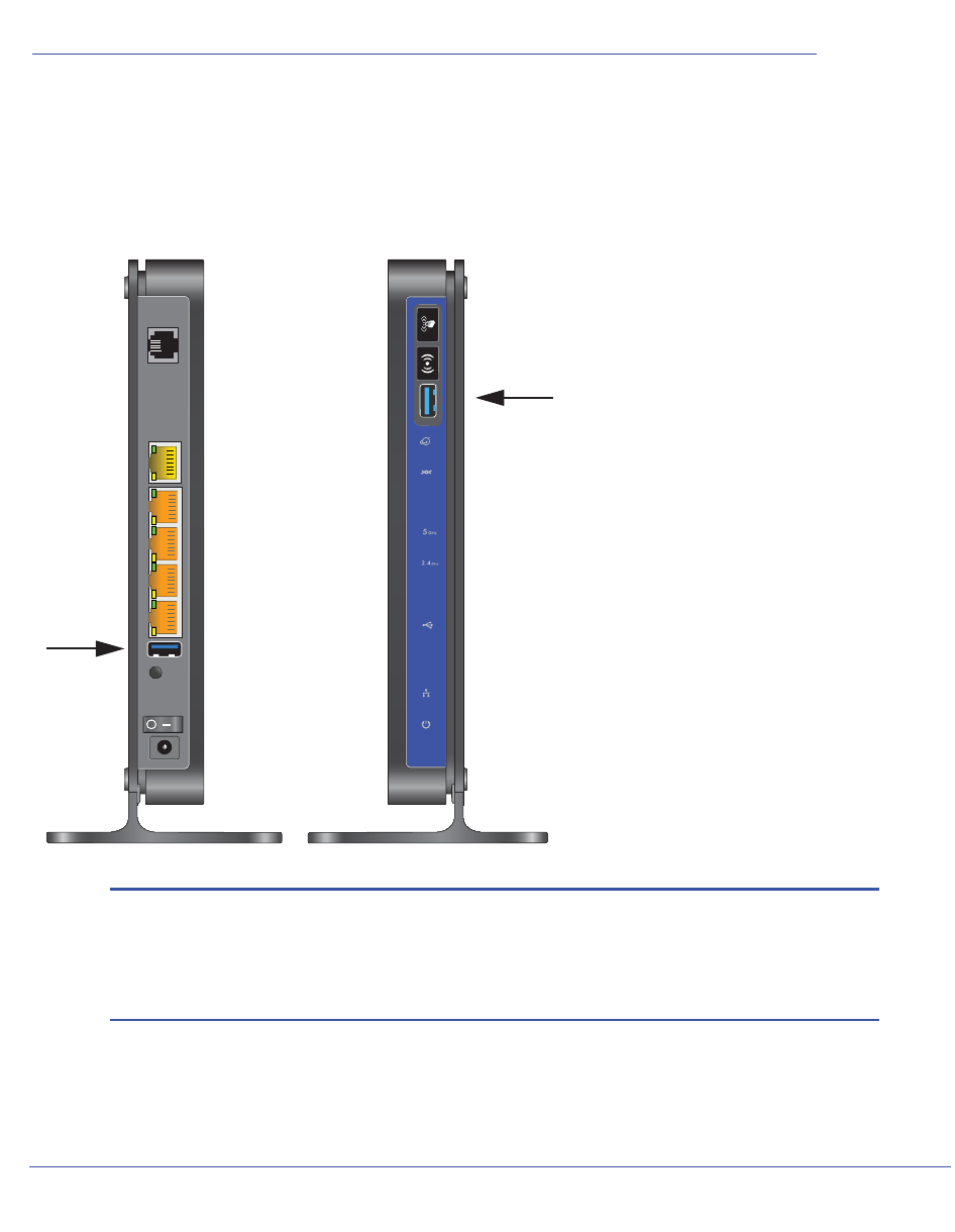
Chapter 6. USB Storage | 72
6
6. USB Storage
Adding removable storage to your network
This chapter describes how to access and configure a USB storage drive attached to your
wireless modem router.
Note: The USB ports on the wireless modem router can be used only to
connect USB storage devices like flash drives or hard drives. Do not
connect computers, USB modems, printers, CD drives, or DVD
drives to the these USB ports.
This chapter includes the following sections:
•USB Drive Requirements
Chapter 6. USB Storage | 73
N600 Wireless Dual Band Gigabit ADSL2+ Modem Router DGND3700 User Manual
•File-Sharing Scenarios
•USB Storage Basic Settings
•Configuring USB Storage Advanced Settings
•Unmounting a USB Drive
•Specifying Approved USB Devices
•Connecting to the USB Drive from a Remote Computer
•Connecting to the USB Drive with Microsoft Network Settings
•Setting Up a Media Server
USB Drive Requirements
The wireless modem router works with 1.0 and 1.1 (USB Full Speed) and 2.0 (USB High
Speed) standards. The approximate USB bus speeds are shown in the following table.
Table 12. USB Bus Speeds
Bus Speed/Second
USB 1.1 12 Mbits
USB 2.0 480 Mbits
Actual bus speeds can vary, depending on the CPU speed, memory, speed of the network,
and other variables. The wireless modem router should work with USB 2.0-compliant or
1.1-compliant external flash and hard drives. For the most up-to-date list of USB drives
supported by the wireless modem router, go to
http://support.netgear.com/app/answers/detail/a_id/18620.
When selecting a USB device, bear in mind the following:
•The USB port on the wireless modem router can be used with one USB hard drive at a
time. Do not attempt to use a USB hub attached to the USB port.
•According to the USB 2.0 specification, the maximum available power is 5V @ 0.5A.
Some USB devices might exceed this requirement, in which case the device might not
function or might function erratically. Check the documentation for your USB device to be
sure.
•The wireless modem router supports FAT, FAT32, NTFS (read only), and Linux file
systems.
File-Sharing Scenarios
You can share files on the USB drive for a wide variety of business and recreational
purposes. The files can be any PC, Mac, or Linux file type including text files, Word,
PowerPoint, Excel, MP3, pictures, and multimedia. USB drive applications include:

74 | Chapter 6. USB Storage
N600 Wireless Dual Band Gigabit ADSL2+ Modem Router DGND3700 User Manual
•Sharing multimedia with friends and family. You can share MP3 files, pictures, and other
multimedia with local and remote users.
•Sharing resources on your network. Store files in a central location so that you do not
have to power up a computer to perform local sharing. In addition, you can share files
between Macintosh, Linux, and PC computers by using the USB drive as a go-between
the systems.
•Sharing files with offsite coworkers. Share files such as Word documents, PowerPoint
presentations, and text files with remote users.
A few common uses are described in the following sections.
Sharing Photos with Friends and Family
You can create your own central storage location for photos and multimedia. This eliminates
the need to log in to (and pay for) an external photo-sharing site.
To share files with your friends and family:
1. Insert your USB drive into the USB port on the wireless modem router either directly or
with a USB cable.
Computers on your local area network (LAN) can access this USB drive using a Web
browser or Microsoft networking.
2. If you want to specify read-only access, or to allow access from the Internet, see Configuring
USB Storage Advanced Settings on page 78.
Storing Files in a Central Location for Printing
This scenario is for a family that has one high-quality color printer directly attached to a PC,
but not shared on the local area network (LAN). This family does not have a print server:
•The family’s color printer is directly attached to the mother’s PC.
•The daughter has some photos on her Macintosh computer that she wants to print.
•Their computers are not visible to each other on the network.
To print her photos on the color printer:
1. The daughter types \\readyshare in the address field of her Web browser.
This gives her access to the USB drive in the router.
2. She copies the photos from the Mac to the router USB drive.
3. The mother uses a her Web browser or Microsoft Networking to transfer the files from the
USB drive to her PC. Then she prints the files.
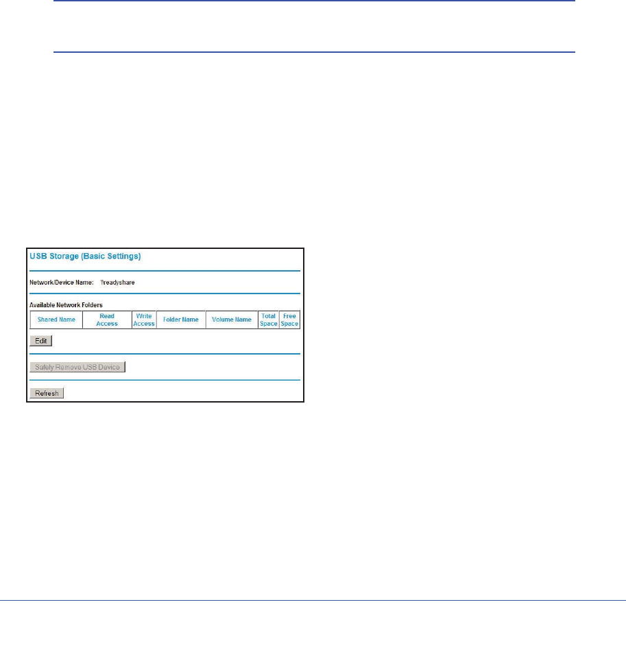
Chapter 6. USB Storage | 75
N600 Wireless Dual Band Gigabit ADSL2+ Modem Router DGND3700 User Manual
Sharing Large Files with Colleagues
Sending files larger than 5 MB can pose a problem for many e-mail systems. The router
allows you to share very large files such as PowerPoint presentations or .zip files with
colleagues at another site. Rather than tying up their mail systems will large files, your
colleagues can use FTP to easily download shared files from the wireless modem router.
To share files with a remote colleague:
1. To protect your network, set up security. Create a user name and password for the
colleague with appropriate access.
2. If you want to limit USB drive access to only Read Access, from the wireless modem router
USB Storage (Basic Settings) screen, click Edit a Network folder. In the Write Access
field, select admin, and then click Apply.
Note: The password for admin is the same one that you use to access the
wireless modem router. By default it is password.
3. Enable FTP via Internet in the USB Storage (Advanced Settings) screen. See Configuring
USB Storage Advanced Settings on page 78.
USB Storage Basic Settings
You can view or edit basic settings for the USB storage device attached to your wireless
modem router. On the wireless modem router main menu under USB, select Basic Settings.
The following screen displays:
By default, the USB storage device is available to all computers on your local area network
(LAN). To access your USB device from this screen, you can click the Network/Device
Name or the Share Name.
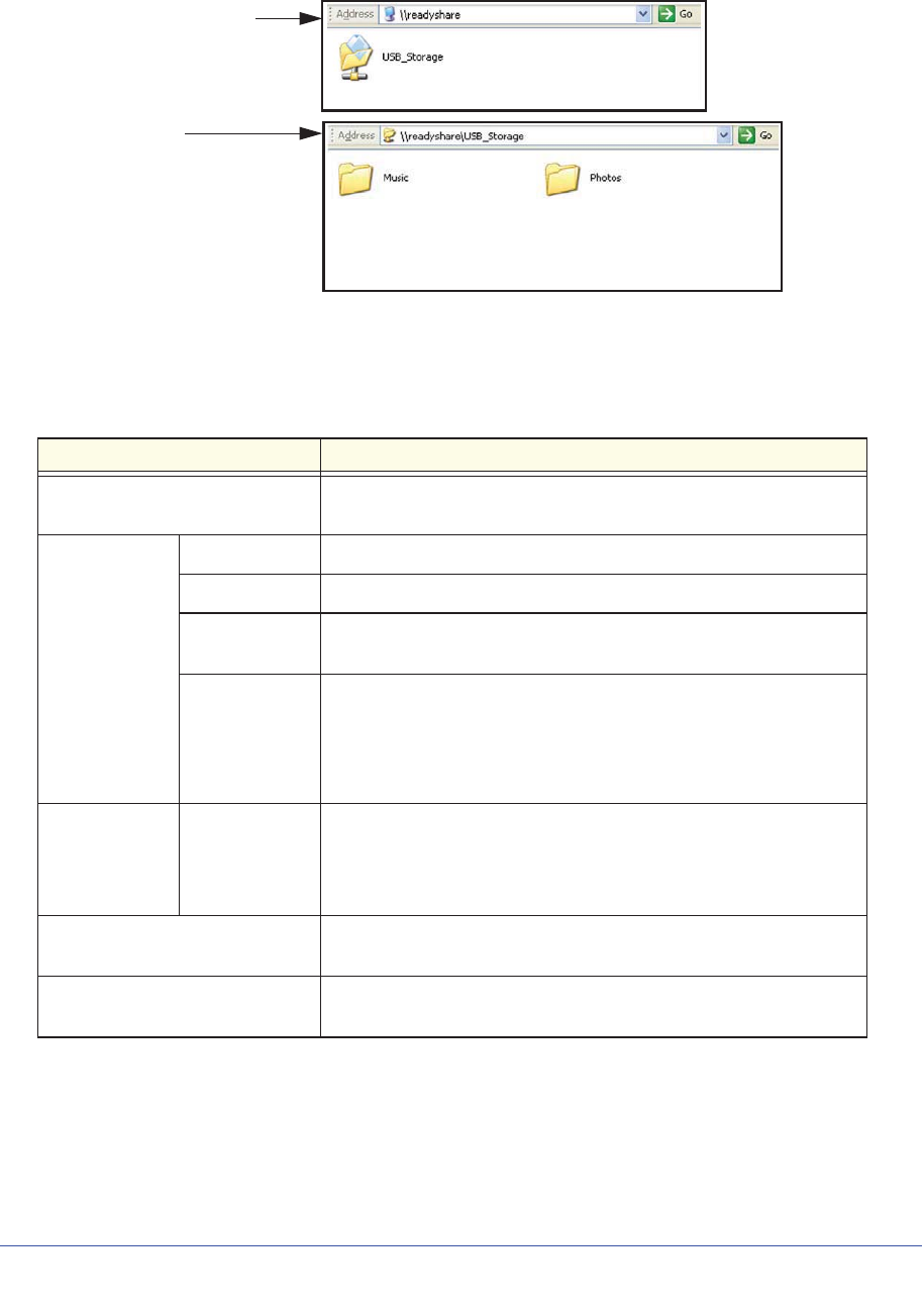
Network/Device Name:
Share Name:
\\readyshare
\\readyshare\USB_Storage
76 | Chapter 6. USB Storage
N600 Wireless Dual Band Gigabit ADSL2+ Modem Router DGND3700 User Manual
You can also type \\readyshare in the address field of your Web browser. If you logged in to
the wireless modem router before you connected your USB device, you might not see your
USB device in the wireless modem router screens until you log out and then log in again.
Table 13. USB Storage Basic Settings
Fields and Buttons Description
Network Device Name The default is \\readyshare. This is the name used to access the
USB device connected to the wireless modem router.
Available
Network folders Folder Name Full path of the used by the Network folder.
Volume name Volume name from the storage device (either USB drive or HDD).
Total/Free
Space Shows the current utilization of the storage device.
Share Name • You can click the name shown, or you can type it in the address
field of your Web browser.
• If Not Shared is shown, then the default share has been deleted
and no other share for the root folder exists. Click the link to
change this setting.
Available
Network folders
(continued)
Read/Write
Access • Shows the network folder permissions and access controls.
• All no password allows all users to access the network folder.
• admin uses the same password that you use to log in to the
wireless modem router main menu.
Edit button You can click the Edit button to edit the Available Network folder
settings. See Editing a Network Folder on page 77.
Safely Remove USB Device
button Click to safely remove the USB device attached to your wireless
modem router. See Unmounting a USB Drive on page 80.
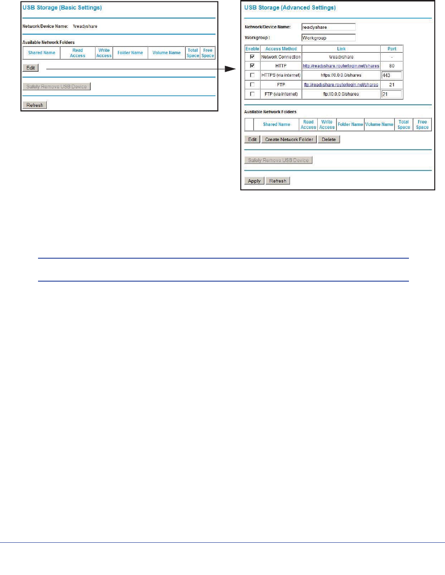
Chapter 6. USB Storage | 77
N600 Wireless Dual Band Gigabit ADSL2+ Modem Router DGND3700 User Manual
Editing a Network Folder
This process is the same from either the USB Storage (Basic Settings) screen or the USB
Storage (Advanced Settings) screen. Click the Edit button to open the Edit Network Folder
screen:
You can use this screen to select a folder, to change the Share Name, or to change Read
Access or Write Access from All-no password to admin. The password for admin is the
same one that is used to log in to the router main menu. By default it is password.
Note: You must click Apply for your changes to take effect.
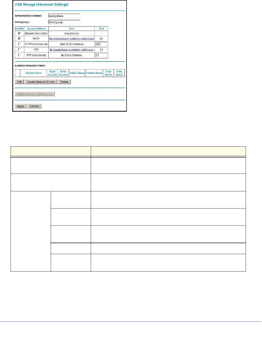
78 | Chapter 6. USB Storage
N600 Wireless Dual Band Gigabit ADSL2+ Modem Router DGND3700 User Manual
Configuring USB Storage Advanced Settings
To configure advanced USB settings, from the router menu, under USB, select Advanced
Settings. The USB Storage (Advanced Settings) screen displays:
You can use this screen to specify access to the USB storage device. The following table
explains the fields and buttons in the USB Storage Advanced Settings screen.
Table 14. USB Storage Advanced Settings
Fields Description
Network Device Name The default is readyshare. This is the name used to access the USB
device connected to the wireless modem router from your computer.
Workgroup If you are using a Windows Workgroup rather than a domain, the
workgroup name is displayed here.
Access Method Network
Connection Enabled by default, this allows all users on the LAN to have access
to the USB drive.
HTTP Disabled by default. If you enable this setting, you can type
http://readyshare to access the USB drive.
HTTP (via
Internet) Disabled by default. If you enable this settings, remote users can
type http://readyshare to access the USB drive over the Internet.
FTP Disabled by default.
FTP (via
Internet) Disabled by default. If you enable this settings, remote users can
access the USB drive via FTP over the Internet.
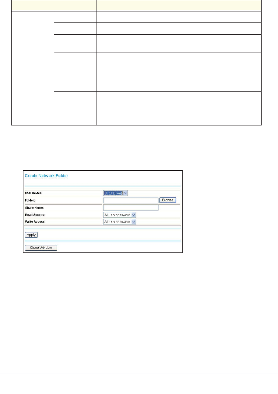
Chapter 6. USB Storage | 79
N600 Wireless Dual Band Gigabit ADSL2+ Modem Router DGND3700 User Manual
Creating a Network Folder
1. From the USB Storage (Advanced Settings) screen, click the Create a Network Folder
button to open the Create a Network Folder screen:
2. Create a folder.
•You can specify the folder’s Share Name,Read Access, and Write Access from
All-no password to admin.
•The password for admin is the same one that is used to log in to the wireless modem
router main menu. By default it is password.
3. Click Apply so that your changes take effect.
Available
Network Folders Folder Name Full path of the used by the Network folder.
Volume name Volume name from the storage device (either USB drive or HDD).
Total/Free
Space The current utilization of the storage device.
Share Name • You can click the name shown or you can type it into the address
field of your Web browser.
• If Not Shared is shown, then the default share has been deleted
and no other share for the root folder exists. Click the link to
change this setting.
Read/Write
Access • Shows the permissions and access controls on the Network folder.
• All no password allows all users to access the Network folder.
• admin prompts you to enter the same password that you use to log
in to the wireless modem router main menu.
Table 14. USB Storage Advanced Settings (Continued)
Fields Description
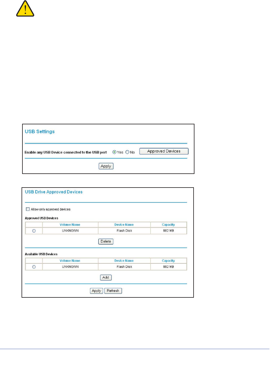
80 | Chapter 6. USB Storage
N600 Wireless Dual Band Gigabit ADSL2+ Modem Router DGND3700 User Manual
Unmounting a USB Drive
WARNING!
Unmount the USB drive first before physically unplugging it from
the wireless modem router. If the USB disk is removed or a cable
is pulled while data is being written to the disk, it could result in
file or disk corruption.
To unmount a USB disk drive so that no users can access it, from the USB Settings screen,
click the Safely Remove USB button. This takes the drive offline.
Specifying Approved USB Devices
You can specify which USB devices are approved for use when connected to the router.
1. On the router main menu, under Advanced, select USB Settings.
2. Click Approved Devices.
3. On the USB Drive Approved Devices screen, select the USB device from the Available
USB Devices list.
4. Click Add.
5. Select the Allow only approved devices check box.

Chapter 6. USB Storage | 81
N600 Wireless Dual Band Gigabit ADSL2+ Modem Router DGND3700 User Manual
6. Click Apply so that your change takes effect.
If you want to approve another USB device, you must first use the Safely Remove USB
Device button to unmount the currently connected USB device. Connect the other USB
device, and then repeat this process.
Connecting to the USB Drive from a Remote Computer
To connect to the USB drive from remote computers using a Web browser, you must use the
router’s Internet port IP address.
Locating the Internet Port IP Address
The Router Status screen shows the Internet port IP address:
1. Log in to the wireless modem router.
2. In the main menu, under Maintenance, select Router Status.
3. Record the IP address that is listed for the Internet port. This is the IP address you can use
to connect to the router remotely.
Accessing the Router’s USB Drive Remotely Using FTP
You can connect to the router’s USB drive using a Web browser:
1. Connect to the router by typing ftp:// and the Internet port IP address in the address field
of Internet Explorer or Netscape Navigator, for example, ftp://10.1.65.4 If you are using
dynamic DNS, you can type the DNS name rather than the IP address.
2. Type the account name and password that has access rights to the USB drive.
3. The directories of the USB drive that your account has access to display, for example,
share/partition1/directory1. You can now read and copy files from the USB directory.
Connecting to the USB Drive with Microsoft Network
Settings
You can access the USB drive from local computers on your home or office network using
Microsoft network settings. You must be running Microsoft Windows 2000, XP, or older
versions of Windows with Microsoft networking enabled. You can use normal Explorer
operations such as dragging and dropping, file opening files, or cutting and pasting files from:
•Microsoft Windows Start menu, Run option
•Windows Explorer
•Network Neighborhood or My Network Place
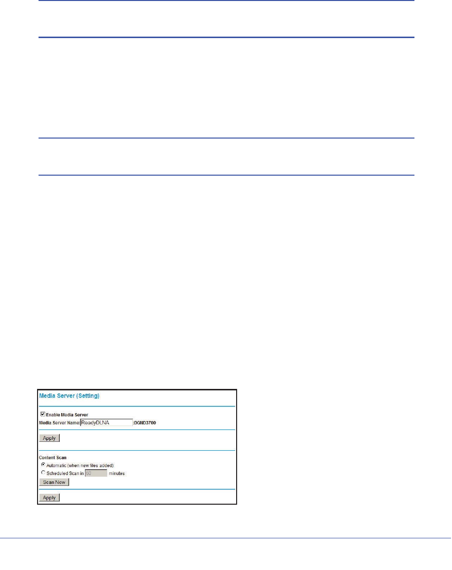
82 | Chapter 6. USB Storage
N600 Wireless Dual Band Gigabit ADSL2+ Modem Router DGND3700 User Manual
Enabling File and Printer Sharing
Each computer’s network properties must be set to enable network communication with the
USB drive. File and Printer Sharing for Microsoft networking must be enabled, as described
in the following sections.
Note: In Windows 2000 and Windows XP, File and Printer Sharing is
enabled by default.
Configuring Windows 98SE and Windows ME
The easiest way to get to your network properties is to go to your desktop, right-click Network
Neighborhood and then select Properties. File and Printer Sharing for Microsoft Windows
should be listed. If not, click Add and follow the installation prompts.
Note: If you have any questions about File and Printer Sharing, contact
Microsoft for assistance.
Configuring Windows 2000 and Windows XP
Right-click on the network connection for your local area network. File and Printer Sharing for
Microsoft Windows should be listed. If not, click Install and follow the installation prompts.
Setting Up a Media Server
Setting the N600 Wireless Modem Router as a ReadyDLNA media server enables playback
of videos, movies, and pictures on DLNA/UPnP AV-compliant Media Players like Xbox360,
Playstation, and NETGEAR's Digital Entertainer Live.
ReadyDLNA means the N600 Wireless Modem Router serves media in DLNA-compatible
form to DLNA/UPnP AV-compliant Media Players.
1. On the main menu, under USB Storage, select Media Server.

Chapter 6. USB Storage | 83
N600 Wireless Dual Band Gigabit ADSL2+ Modem Router DGND3700 User Manual
•Enable Media Server enables the N600 Wireless Modem Router to act as a Media
server.
•Media Server Name is the name that shows up on media players.
•Content Scan -> Automatic Scans for media files whenever new files are added to the
ReadyShare USB storage.
•You can also schedule scan periodically or click Scan Now to scan for new media
immediately.
2. Click Apply to save your settings.

Chapter 7. Virtual Private Networking | 84
7
7. Virtual Private Networking
Setting up secure encrypted communications
This chapter describes how to use the virtual private networking (VPN) features of the wireless
modem router. VPN communications paths are called tunnels. VPN tunnels provide secure,
encrypted communications between your local network and a remote network or computer. See
Appendix B, NETGEAR VPN Configuration.
This chapter is organized as follows:
•Overview of VPN Configuration
•Planning a VPN
•VPN Tunnel Configuration
•Setting Up a Client-to-Gateway VPN Configuration
•Setting Up a Gateway-to-Gateway VPN Configuration
•VPN Tunnel Control
•Setting Up VPN Tunnels in Special Circumstances
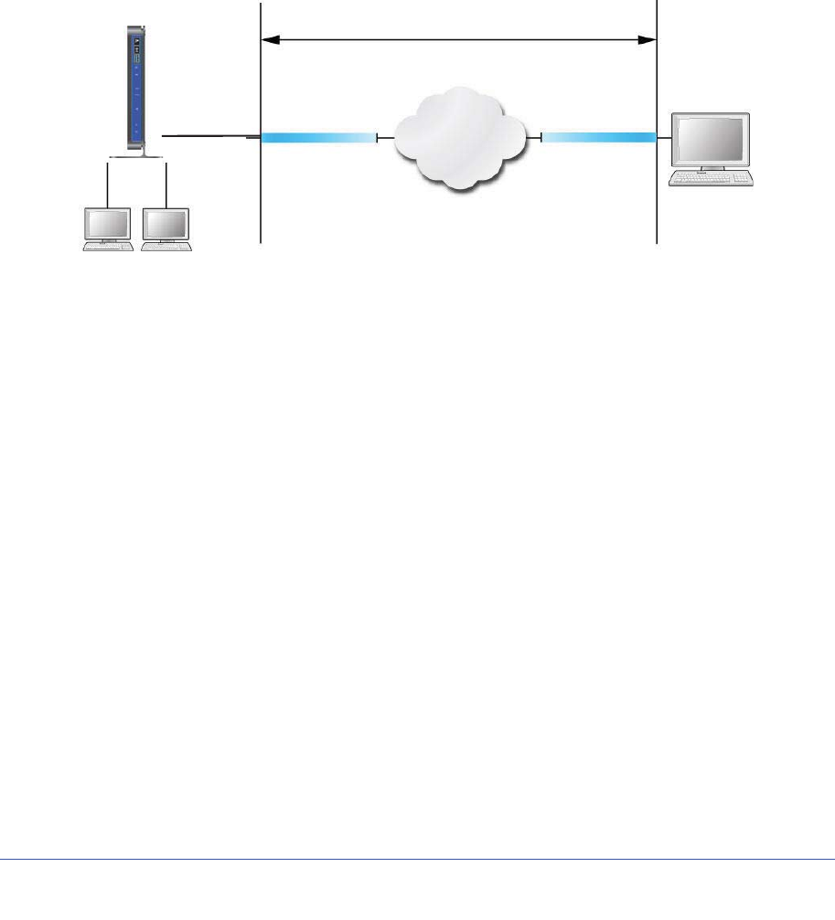
Chapter 7. Virtual Private Networking | 85
N600 Wireless Dual Band Gigabit ADSL2+ Modem Router DGND3700 User Manual
Overview of VPN Configuration
Two common scenarios for VPN tunnels are between a remote PC and a network gateway,
and between two or more network gateways. The N600 Wireless Dual Band Gigabit ADSL2+
Modem Router DGND3700 supports both types. The N600 Wireless Dual Band Gigabit
ADSL2+ Modem Router DGND3700 supports up to five concurrent tunnels.
Client-to-Gateway VPN Tunnels
Client-to-gateway VPN tunnels provide secure access from a remote PC, such as a
telecommuter connecting to an office network.
VPN Tunnel
Internet
PC running NETGEAR
ProSafe VPN client
Modem Router DGND3700
Figure 41. Telecommuter VPN Tunnel
A VPN client access allows a remote PC to connect to your network from any location on the
Internet. The remote PC is one tunnel endpoint, running the VPN client software. The
wireless modem router on your network is the other tunnel endpoint. See Setting Up a
Client-to-Gateway VPN Configuration on page 88 for information about how to set up this
configuration.
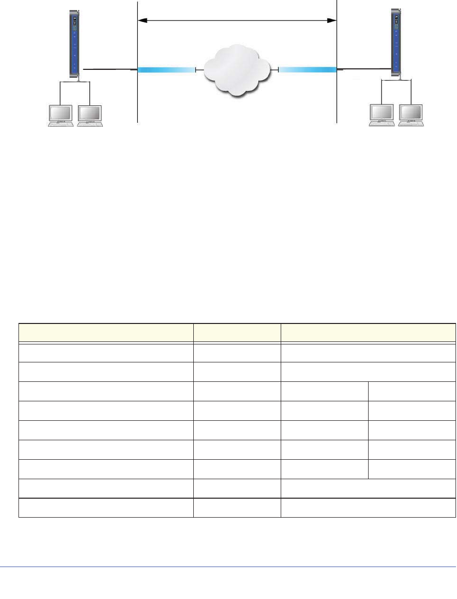
86 | Chapter 7. Virtual Private Networking
N600 Wireless Dual Band Gigabit ADSL2+ Modem Router DGND3700 User Manual
Gateway-to-Gateway VPN Tunnels
Gateway-to-gateway VPN tunnels provide secure access between networks, such as a
branch or home office and a main office.
VPN Tunnel
Internet
Modem Router DGND3700
Gateway A
(Home)
Modem Router DGND3700
Gateway B
(Office)
Figure 42. VPN Tunnel between Networks
A VPN between two or more NETGEAR VPN-enabled routers is a good way to connect
branch or home offices and business partners over the Internet. VPN tunnels also enable
access to network resources across the Internet. In this case, use gateways on each end of
the tunnel to form the VPN tunnel end points. See Setting Up a Gateway-to-Gateway VPN
Configuration on page 99 for information about how to set up this configuration.
Planning a VPN
When you set up a VPN, it is helpful to plan the network configuration and record the
configuration parameters on a worksheet:
Table 15. VPN Tunnel Configuration Worksheet
Parameter Value to Be Entered Field Selection
Connection Name N/A
Pre-Shared Key N/A
Secure Association N/A Main Mode Manual Keys
Perfect Forward Secrecy N/A Enabled Disabled
Encryption Protocol N/A DES 3DES
Authentication Protocol N/A MD5 SHA-1
Diffie-Hellman (DH) Group N/A Group 1 Group 2
Key Life in seconds N/A
IKE Life Time in seconds N/A
Chapter 7. Virtual Private Networking | 87
N600 Wireless Dual Band Gigabit ADSL2+ Modem Router DGND3700 User Manual
To set up a VPN connection, you must configure each endpoint with specific identification
and connection information describing the other endpoint. You must configure the outbound
VPN settings on one end to match the inbound VPN settings on other end, and vice versa.
This set of configuration information defines a security association (SA) between the two
VPN endpoints. When planning your VPN, you must make a few choices first:
•Will the local end be any device on the LAN, a portion of the local network (as defined by
a subnet or by a range of IP addresses), or a single PC?
•Will the remote end be any device on the remote LAN, a portion of the remote network
(as defined by a subnet or by a range of IP addresses), or a single PC?
•Will either endpoint use fully qualified domain names (FQDNs)? FQDNs supplied by
Dynamic DNS providers (see Using a Fully Qualified Domain Name (FQDN) on
page 161) can allow a VPN endpoint with a dynamic IP address to initiate or respond to a
tunnel request. Otherwise, the side using a dynamic IP address must always be the
initiator.
•Which method will you use to configure your VPN tunnels?
-The VPN Wizard using VPNC defaults (see Table 16)
-The typical automated Internet Key Exchange (IKE) setup (see Using Auto Policy to
Configure VPN Tunnels on page 110)
-A manual keying setup in which you must specify each phase of the connection (see
Using Manual Policy to Configure VPN Tunnels on page 117)
Table 16. Parameters Recommended by the VPNC and Used in the VPN Wizard
Parameter Factory Default Setting
Secure Association Main Mode
Authentication Method Pre-Shared Key
Encryption Method 3DES
Authentication Protocol SHA-1
Diffie-Hellman (DH) Group Group 2 (1024 bit)
Key Life 8 hours
IKE Life Time 1 hour
•What level of IPSec VPN encryption will you use?
VPN Endpoint Local IPSecID LAN IP Address Subnet Mask FQDN or Gateway
IP (WAN IP Address
Table 15. VPN Tunnel Configuration Worksheet
Parameter Value to Be Entered Field Selection

88 | Chapter 7. Virtual Private Networking
N600 Wireless Dual Band Gigabit ADSL2+ Modem Router DGND3700 User Manual
-DES. The Data Encryption Standard (DES) processes input data that is 64 bits wide,
encrypting these values using a 56-bit key. Faster but less secure than 3DES.
-3DES. Triple DES achieves a higher level of security by encrypting the data three
times using DES with three different, unrelated keys.
•What level of authentication will you use?
-MDS. 128 bits, faster but less secure.
-SHA-1. 160 bits, slower but more secure.
VPN Tunnel Configuration
There are two tunnel configurations and three ways to configure them:
•Use the VPN Wizard to configure a VPN tunnel (recommended for most situations):
-See Setting Up a Client-to-Gateway VPN Configuration on page 88.
-See Setting Up a Gateway-to-Gateway VPN Configuration on page 99.
•See Using Auto Policy to Configure VPN Tunnels on page 110 when the VPN Wizard and
its VPNC defaults (see Table 16 on page 87) are not appropriate for your special
circumstances, but you want to automate the Internet Key Exchange (IKE) setup.
•See Using Manual Policy to Configure VPN Tunnels on page 117 when the VPN Wizard
and its VPNC defaults (see Table 16 on page 87) are not appropriate for your special
circumstances and you must specify each phase of the connection. You manually enter
all the authentication and key parameters. You have more control over the process;
however, the process is more complex, and there are more opportunities for errors or
configuration mismatches between your N600 Wireless Dual Band Gigabit ADSL2+
Modem Router DGND3700 and the corresponding VPN endpoint gateway or client
workstation.
Setting Up a Client-to-Gateway VPN Configuration
Setting up a VPN between a remote PC running the NETGEAR ProSafe VPN client and a
network gateway involves two steps, described in the following sections:
•Step 1: Configure the Client-to-Gateway VPN Tunnel on page 89 describes how to use
the VPN Wizard to configure the VPN tunnel between the remote PC and network
gateway.
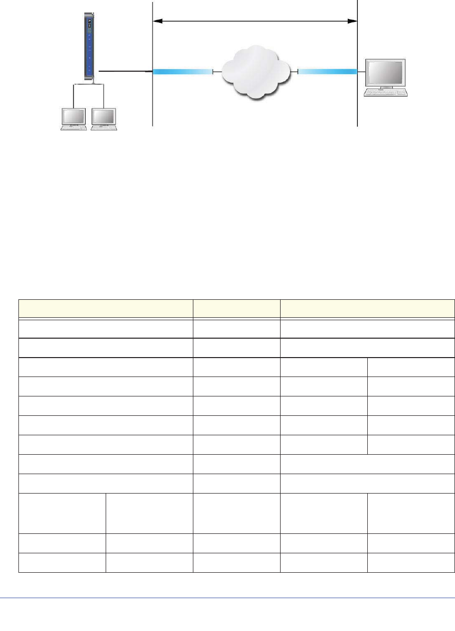
Chapter 7. Virtual Private Networking | 89
N600 Wireless Dual Band Gigabit ADSL2+ Modem Router DGND3700 User Manual
•Step 2: Configure the NETGEAR ProSafe VPN Client on page 92 shows how to configure
the NETGEAR ProSafe VPN client endpoint.
VPN tunnel
Internet
PC running NETGEAR
ProSafe VPN client
22.23.24.25 0.0.0.0
IP: 192.168.3.1
Figure 43. Wireless Modem Router DGND3700 Client-to-Gateway VPN Tunnel
Step 1: Configure the Client-to-Gateway VPN Tunnel
This section describes using the VPN Wizard to set up the VPN tunnel using the VPNC
default parameters listed in Table 16 on page 87. If you have special requirements not
covered by these VPNC-recommended parameters, see Setting Up VPN Tunnels in Special
Circumstances on page 109 for information about how to set up the VPN tunnel.
The following worksheet identifies the parameters used in this procedure. For a blank
worksheet, see Planning a VPN on page 86.
Table 17. VPN Tunnel Configuration Worksheet
Parameter Value to Be Entered Field Selection
Connection Name RoadWarrior N/A
Pre-Shared Key 12345678 N/A
Secure Association N/A Main Mode Manual Keys
Perfect Forward secrecy N/A Enabled Disabled
Encryption Protocol N/A DES 3DES
Authentication Protocol N/A MD5 SHA-1
Diffie-Hellman (DH) Group N/A Group 1 Group 2
Key Life in seconds 28800 (8 hours) N/A
IKE Life Time in seconds 3600 (1 hour) N/A
VPN Endpoint Local IPSecID LAN IP Address Subnet Mask FQDN or Gateway
IP (WAN IP
Address)
Client toGateway N/A N/A Dynamic
Gateway toClient 192.168.3.1 255.255.255.0 22.23.24.25
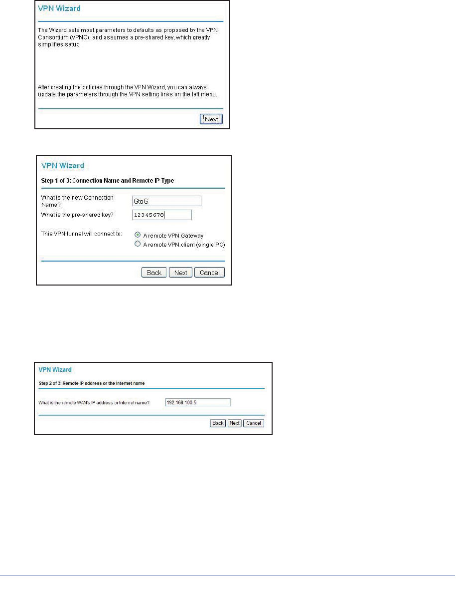
90 | Chapter 7. Virtual Private Networking
N600 Wireless Dual Band Gigabit ADSL2+ Modem Router DGND3700 User Manual
To configure a client-to-gateway VPN tunnel using the VPN Wizard:
1. Log in to the wireless modem router. On the main menu under Advanced - VPN, select
VPN Wizard.
2. Click Next to proceed.
3. Fill in the Connection Name and pre-shared key fields.
The connection name is for convenience and does not affect how the VPN tunnel
functions.
4. Select the radio button for the type of target end point, and click Next.
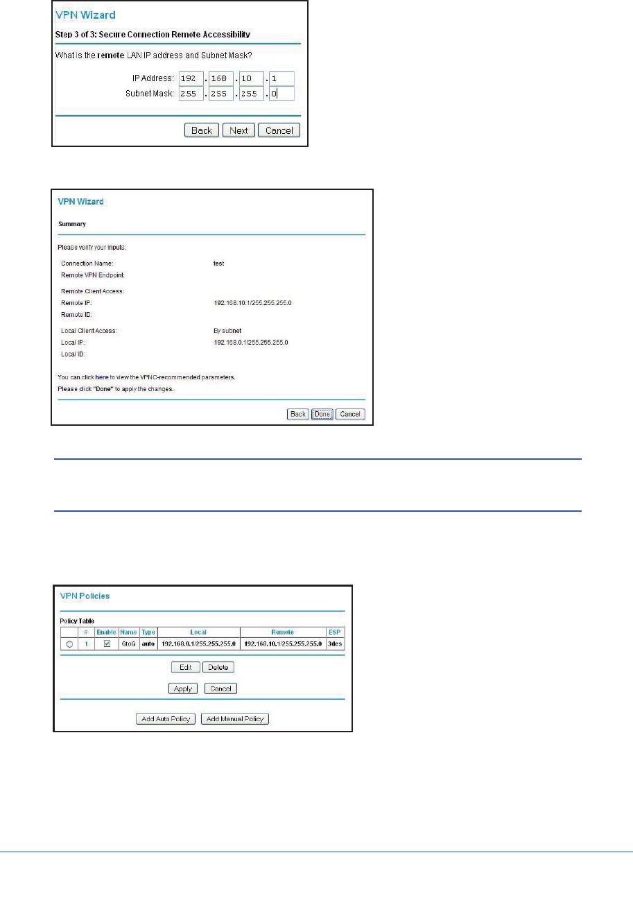
Chapter 7. Virtual Private Networking | 91
N600 Wireless Dual Band Gigabit ADSL2+ Modem Router DGND3700 User Manual
5. Enter the remote IP address, and click Next.
The Summary screen displays:
Note: To view the VPNC-recommended authentication and encryption
settings used by the VPN Wizard, click the here link.
6. Click Done on the Summary screen. The VPN Policies screen displays, showing that the
new tunnel is enabled:
To view or modify the tunnel settings, select its radio button and click Edit.

92 | Chapter 7. Virtual Private Networking
N600 Wireless Dual Band Gigabit ADSL2+ Modem Router DGND3700 User Manual
Note: See Using Auto Policy to Configure VPN Tunnels on page 110 for
information about how to enable the IKE keep-alive capability on an existing
VPN tunnel.
Step 2: Configure the NETGEAR ProSafe VPN Client
This section describes how to configure the NETGEAR ProSafe VPN client on a remote PC.
These instructions assume that the PC running the client has a dynamically assigned IP
address.
The PC must have the NETGEAR ProSafe VPN Client program installed that supports
IPSec. Go to the NETGEAR website (http://www.netgear.com) for information about how to
purchase the NETGEAR ProSafe VPN Client.
Note: Before installing the NETGEAR ProSafe VPN Client software, be
sure to turn off any virus protection or firewall software you might be
running on your PC. You might need to insert your Windows CD to
complete the installation.
1. Install the NETGEAR ProSafe VPN client on the remote PC, and then reboot.
a. Install the IPSec component. You might have the option to install either the VPN
adapter or the IPSec component or both. The VPN adapter is not necessary.
If you do not have a modem or dial-up adapter installed in your PC, you might see the
warning message stating “The NETGEAR ProSafe VPN Component requires at least
one dial-up adapter be installed.” You can disregard this message.
b. Reboot the remote PC.
The ProSafe icon ( ) is in the system tray.
c. Double-click the ProSafe icon to open the Security Policy Editor.
2. Add a new connection.
a. Run the NETGEAR ProSafe Security Policy Editor program, and, using the Table 17
on page 89, create a VPN connection.
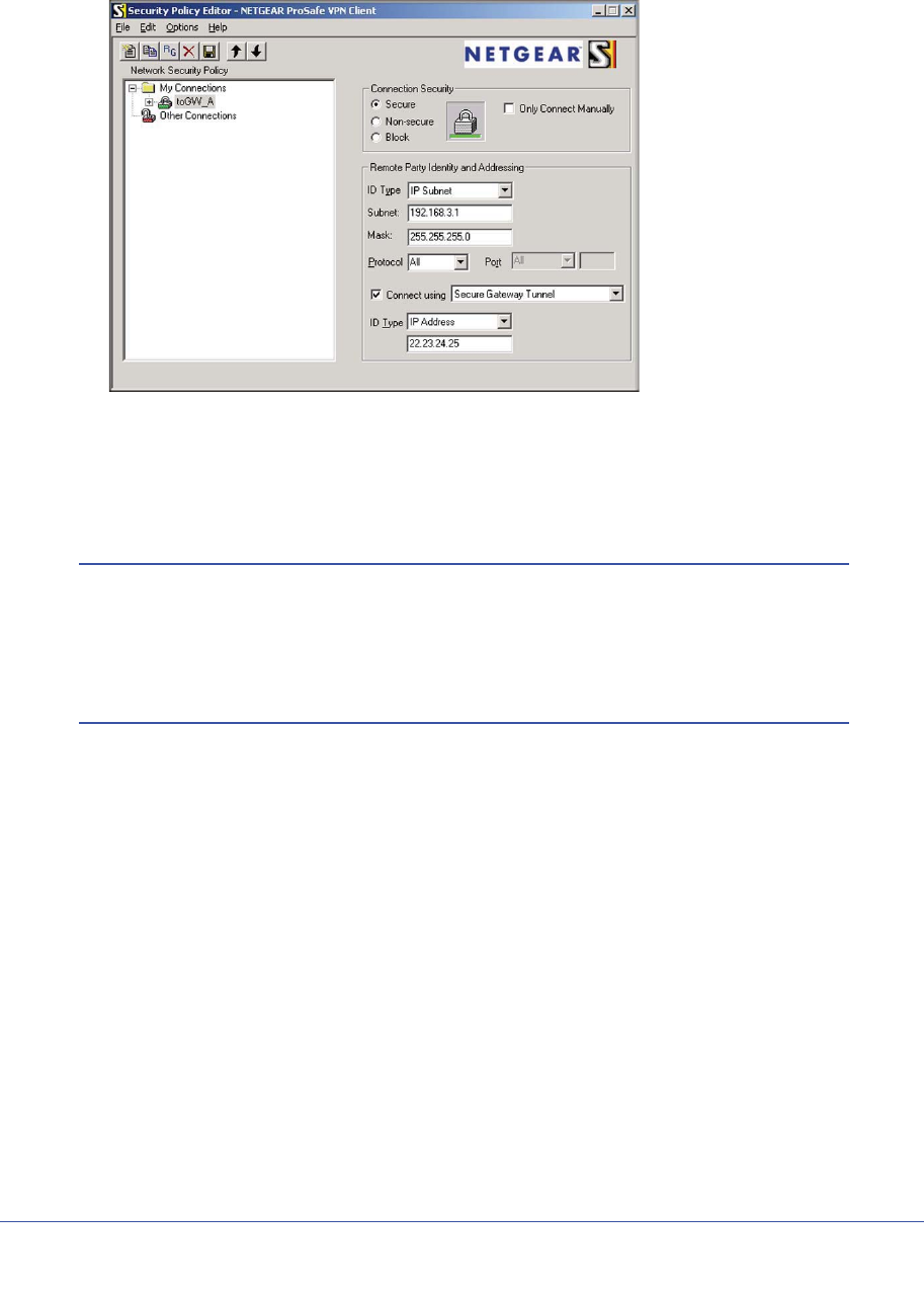
Chapter 7. Virtual Private Networking | 93
N600 Wireless Dual Band Gigabit ADSL2+ Modem Router DGND3700 User Manual
b. From the Edit menu of the Security Policy Editor, select Add, and then click
Connection.
A New Connection listing appears in the list of policies.
c. Rename the new connection so that it matches the Connection Name field in the
VPN Settings screen of the wireless modem router on LAN A. Choose connection
names that make sense to the people using and administering the VPN.
Note: In this example, the connection name used on the client side of the
VPN tunnel is togw_a, and it does not have to match the
RoadWarrior connection name used on the gateway side of the VPN
tunnel because connection names are irrelevant to how the VPN
tunnel functions.
d. Enter the following settings:
•Connection Security. Select Secure.
•ID Type. Select IP Subnet.
•Subnet. In this example, type 192.168.3.1 as the network address of the wireless
modem router.
•Mask. Enter 255.255.255.0 as the LAN subnet mask of the wireless modem
router.
•Protocol. Select All to allow all traffic through the VPN tunnel.
e. Select the Connect using Secure Gateway Tunnel check box.
f. In the ID Type drop-down list, select IP Address.
g. Enter the public WAN IP address of the wireless modem router in the field directly
below the ID Type drop-down list. In this example, 22.23.24.25 is used.
The resulting connection settings are shown in Figure 44 on page 94.
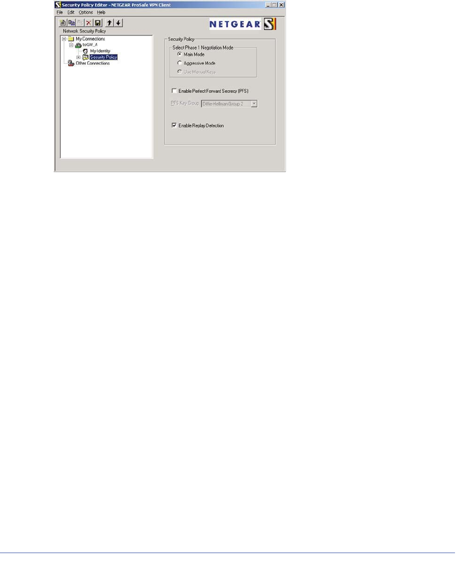
94 | Chapter 7. Virtual Private Networking
N600 Wireless Dual Band Gigabit ADSL2+ Modem Router DGND3700 User Manual
3. Configure the security policy in the NETGEAR ProSafe VPN Client software:
a. In the Network Security Policy list, expand the new connection by double-clicking its
name or clicking the + symbol. My Identity and Security Policy subheadings appear
below the connection name.
b. Click the Security Policy subheading to view the Security Policy settings.
Figure 44. Security Policy settings, Client-to-Gateway A
c. In the Select Phase 1 Negotiation Mode section of the screen, select the Main Mode
radio button.
4. Configure the VPN client identity.
In this step, you provide information about the remote VPN client PC. You must provide
the pre-shared key that you configured in the wireless modem router and either a fixed IP
address or a fixed virtual IP address of the VPN client PC.
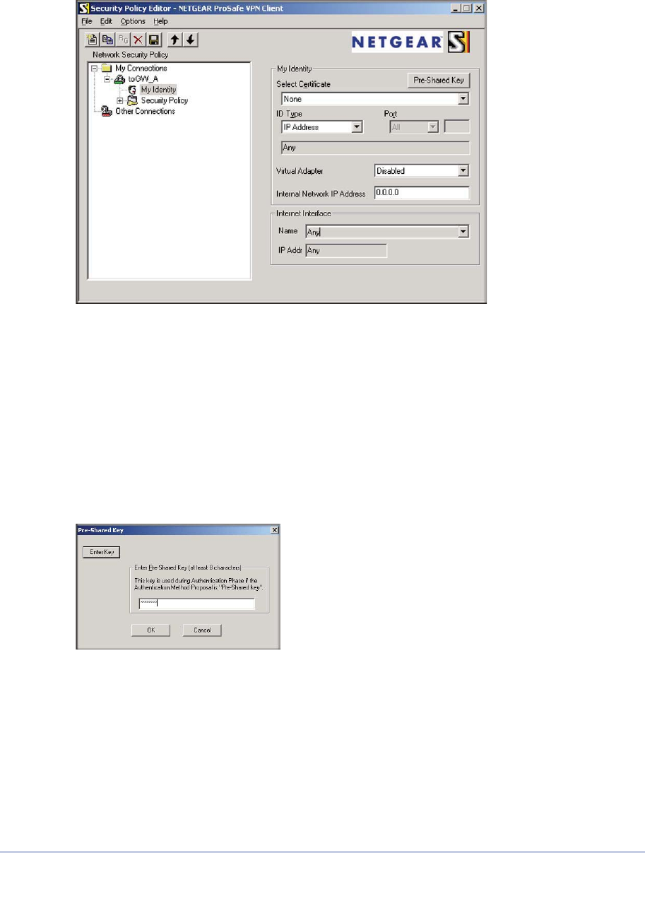
Chapter 7. Virtual Private Networking | 95
N600 Wireless Dual Band Gigabit ADSL2+ Modem Router DGND3700 User Manual
a. In the Network Security Policy list on the left side of the Security Policy Editor window,
click My Identity.
b. In the Select Certificate drop-down list, select None.
c. In the ID Type drop-down list, select IP Address. If you are using a virtual fixed IP
address, enter this address in the Internal Network IP Address field. Otherwise,
leave this field empty.
d. In the Internet Interface section of the screen, select the adapter that you use to
access the Internet. If you have a dial-up Internet account, select PPP Adapter in
the Name list. If you have a dedicated cable or ADSL line, select your Ethernet
adapter. If you will be switching between adapters or if you have only one adapter,
select Any.
e. In the My Identity section of the screen, click the Pre-Shared Key button. The
Pre-Shared Key screen displays:
f. Click Enter Key. Enter the wireless modem router pre-shared key, and then click
OK. In this example, 12345678 is entered, though asterisks are displayed in the
field. This field is case-sensitive.
5. Configure the VPN client authentication proposal.
In this step, you provide the type of encryption (DES or 3DES) to be used for this
connection. This selection must match your selection in the wireless modem router
configuration.
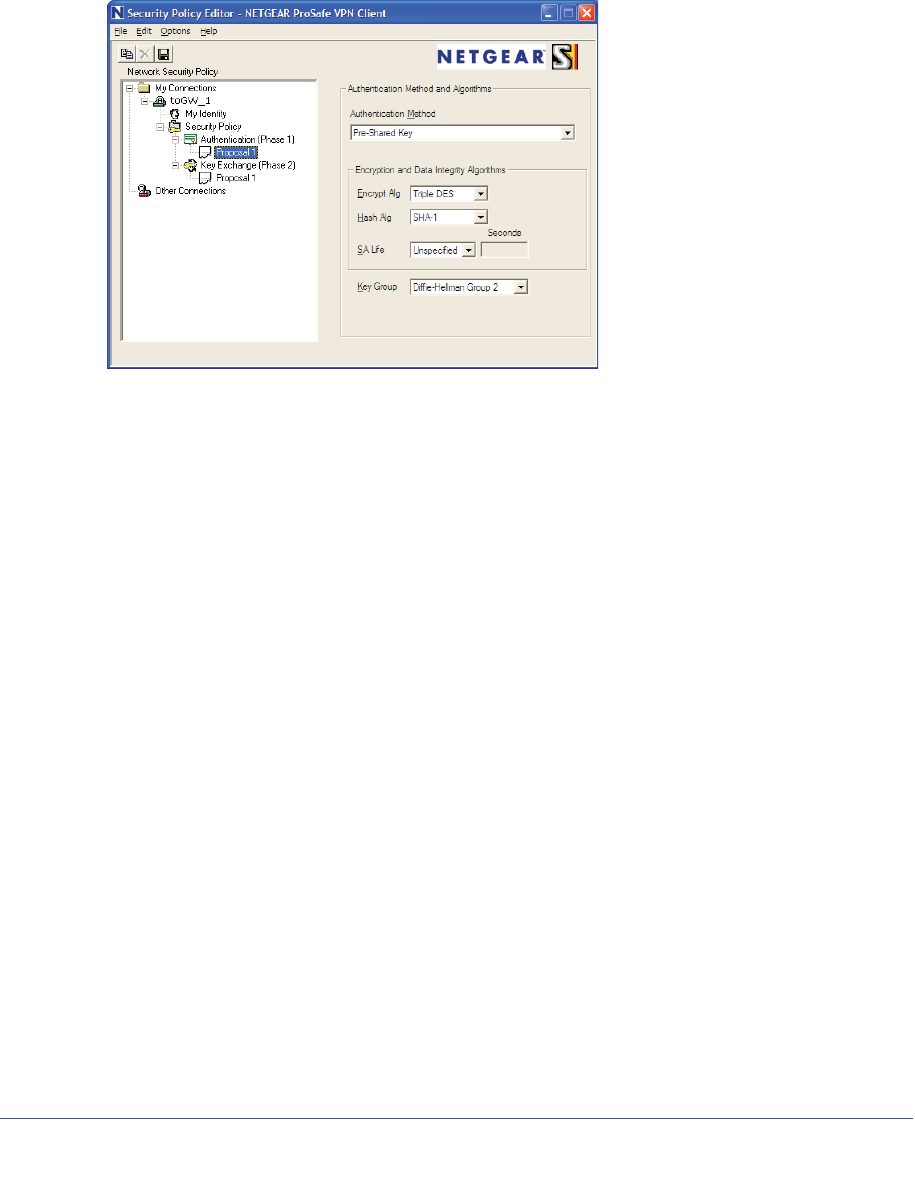
96 | Chapter 7. Virtual Private Networking
N600 Wireless Dual Band Gigabit ADSL2+ Modem Router DGND3700 User Manual
a. In the Network Security Policy list on the left side of the Security Policy Editor window,
expand the Security Policy heading by double-clicking its name or clicking the +
symbol.
b. Expand the Authentication subheading by double-clicking its name or clicking the +
symbol. Then select Proposal 1 below Authentication.
c. In the Authentication Method drop-down list, select Pre-Shared key.
d. In the Encrypt Alg drop-down list, select the type of encryption that is configured for
the encryption protocol in the wireless modem router, as listed in Table 15 on
page 86. This example uses Triple DES.
e. In the Hash Alg drop-down list, select SHA-1.
f. In the SA Life drop-down list, select Unspecified.
g. In the Key Group drop-down list, select Diffie-Hellman Group 2.
6. Configure the VPN client key exchange proposal.
In this step, you provide the type of encryption (DES or 3DES) to be used for this
connection. This selection must match your selection in the wireless modem router
configuration.
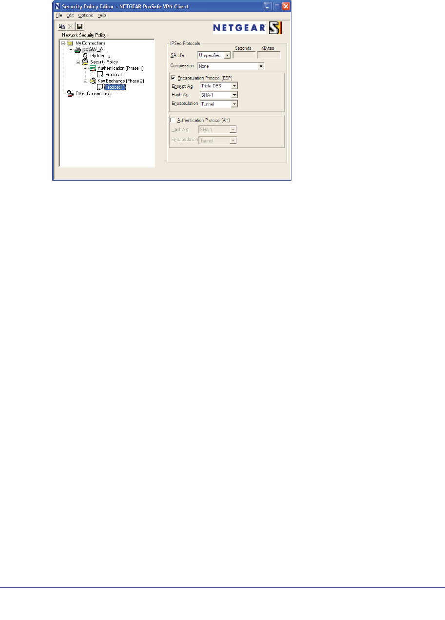
Chapter 7. Virtual Private Networking | 97
N600 Wireless Dual Band Gigabit ADSL2+ Modem Router DGND3700 User Manual
a. Expand the Key Exchange subheading by double-clicking its name or clicking the +
symbol. Then select Proposal 1 below Key Exchange.
b. In the SA Life drop-down list, select Unspecified.
c. In the Compression drop-down list, select None.
d. Select the Encapsulation Protocol (ESP) check box.
e. In the Encrypt Alg drop-down list, select the type of encryption that is configured for
the encryption protocol in the wireless modem router, as listed in Table 15 on
page 86. This example uses Triple DES.
f. In the Hash Alg drop-down list, select SHA-1.
g. In the Encapsulation drop-down list, select Tunnel.
h. Leave the Authentication Protocol (AH) check box cleared.
7. Save the VPN client settings.
In the Security Policy Editor window, select File > Save.
After you have configured and saved the VPN client information, your PC automatically
opens the VPN connection when you attempt to access any IP addresses in the range of
the remote VPN router’s LAN.
8. Check the VPN connection.
To check the VPN connection, you can initiate a request from the remote PC to the
wireless modem router’s network by using the Connect option in the NETGEAR ProSafe
menu bar. The NETGEAR ProSafe client reports the results of the attempt to connect.
Since the remote PC has a dynamically assigned WAN IP address, it must initiate the
request.
To perform a ping test using our example, start from the remote PC:
a. Establish an Internet connection from the PC.
b. On the Windows taskbar, click the Start button, and then select Run.
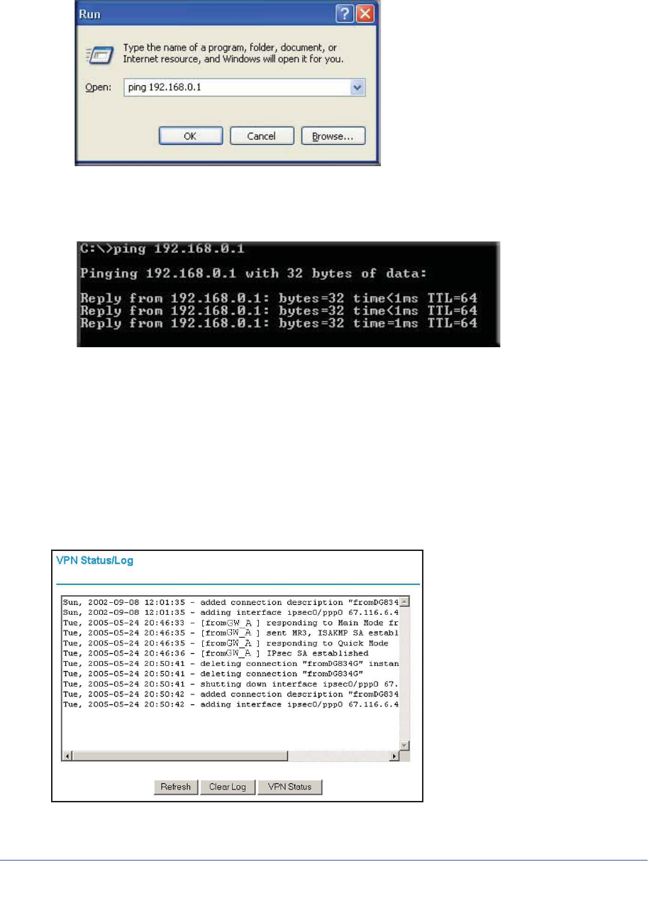
98 | Chapter 7. Virtual Private Networking
N600 Wireless Dual Band Gigabit ADSL2+ Modem Router DGND3700 User Manual
c. Type ping -t 192.168.3.1, and then click OK.
This causes a continuous ping to be sent to the first wireless modem router. After
between several seconds and 2 minutes, the ping response should change from
timed out to reply.
Once the connection is established, you can open a browser on the PC and enter the
LAN IP address of the remote gateway. After a short wait, you should see the login
screen of the wireless modem router (unless another PC is already logged in to the
wireless modem router).
You can view information about the progress and status of the VPN client connection by
opening the NETGEAR ProSafe Log Viewer.
To launch this function, click the Windows Start button, then select Programs >
NETGEAR ProSafe VPN Client > Log Viewer. The Log Viewer screen for a successful
connection is shown in the following figure:
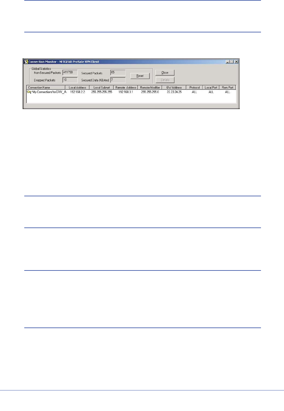
Chapter 7. Virtual Private Networking | 99
N600 Wireless Dual Band Gigabit ADSL2+ Modem Router DGND3700 User Manual
Note: Use the active VPN tunnel information and pings to determine
whether a failed connection is due to the VPN tunnel or some
reason outside the VPN tunnel.
9. The Connection Monitor screen for this connection is shown in the following figure:
In this example you can see these settings:
•The wireless modem router has a GW address (public IP WAN address) of 22.23.24.25.
•The wireless modem router has a remote address (LAN IP address) of 192.168.3.1.
•The VPN client PC has a local address (dynamically assigned address) of 192.168.2.2.
While the connection is being established, the Connection Name field in this screen displays
SA before the name of the connection. When the connection is successful, the SA changes
to the yellow key symbol shown in the previous figure.
Note: While your PC is connected to a remote LAN through a VPN, you
might not have normal Internet access. If this is the case, you must
close the VPN connection to have normal Internet access.
Setting Up a Gateway-to-Gateway VPN Configuration
Note: This section describes how to use the VPN Wizard to set up the
VPN tunnel using the VPNC default parameters listed in Table 16 on
page 87. If you have special requirements not covered by these
VPNC-recommended parameters, see Setting Up VPN Tunnels in
Special Circumstances on page 109 for information about how to set
up the VPN tunnel.
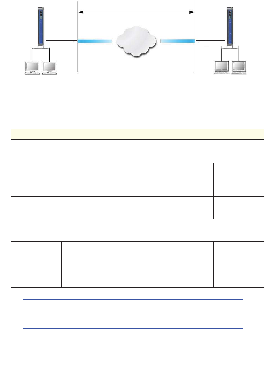
100 | Chapter 7. Virtual Private Networking
N600 Wireless Dual Band Gigabit ADSL2+ Modem Router DGND3700 User Manual
Follow this procedure to configure a gateway-to-gateway VPN tunnel using the VPN Wizard.
VPN tunnel
Internet
IP: 192.168.0.1 IP:192.168.3.1
Gateway B
Gateway A
22.23.24.25
14.15.16.17
Figure 45. Gateway-to-Gateway VPN Tunnel
Set the LAN IPs on each wireless modem router to different subnets and configure each
correctly for the Internet. The subsequent examples assume the settings shown in the
following table.
Table 18. Gateway-to-Gateway VPN Tunnel Configuration Worksheet
Parameter Value to Be Entered Field Selection
Connection Name GtoGr N/A
Pre-Shared Key 12345678 N/A
Secure Association N/A Main Mode Manual Keys
Perfect Forward Secrecy N/A Enabled Disabled
Encryption Protocol N/A DES 3DES
Authentication Protocol N/A MD5 SHA-1
Diffie-Hellman (DH) Group N/A Group 1 Group 2
Key Life in seconds 28800 (8 hours) N/A
IKE Life Time in seconds 3600 (1 hour) N/A
VPN Endpoint Local IPSecID LAN IP Address Subnet Mask FQDN or Gateway
IP (WAN IP
Address)
Gateway_A GW_A 192.168.0.1 255.255.255.0 14.15.16.17
Gateway_B GW_B 192.168.3.1 255.255.255.0 22.23.24.25
Note: The LAN IP address ranges of each VPN endpoint must be different.
The connection will fail if both are using the NETGEAR default
address range of 192.168.0.x.
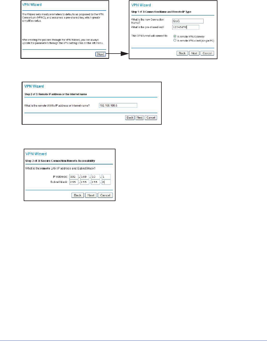
Chapter 7. Virtual Private Networking | 101
N600 Wireless Dual Band Gigabit ADSL2+ Modem Router DGND3700 User Manual
To configure a gateway-to-gateway VPN tunnel using the VPN Wizard:
1. Log in to Gateway A on LAN A. From the main menu, select VPN Wizard. Click Next,
and the Step 1 of 3 screen displays.
2. Fill in the Connection Name and pre-shared key fields. Select the radio button for the type of
target end point, and click Next, and the Step 2 of 3 screen displays.
3. Fill in the IP address or FQDN for the target VPN endpoint WAN connection, and click Next.
and the Step 3 of 3 screen displays.
4. Fill in the IP Address and Subnet Mask fields for the target endpoint that can use this tunnel,
and click Next.
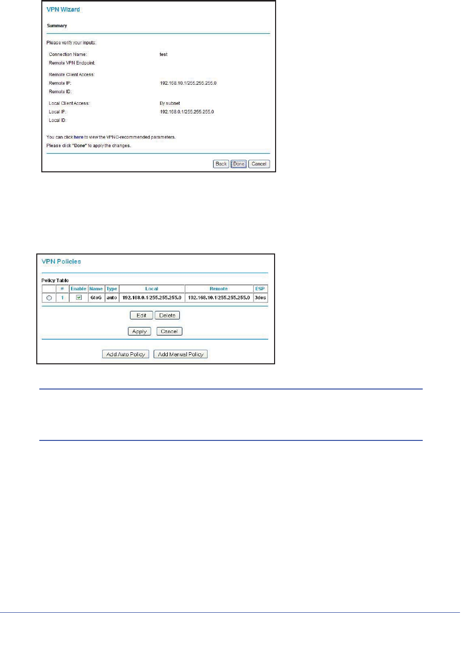
102 | Chapter 7. Virtual Private Networking
N600 Wireless Dual Band Gigabit ADSL2+ Modem Router DGND3700 User Manual
The VPN Wizard Summary screen displays:
To view the VPNC-recommended authentication and encryption settings used by the
VPN Wizard, click the here link.
5. Click Done on the Summary screen.
The VPN Policies screen displays, showing that the new tunnel is enabled.
Note: See Using Auto Policy to Configure VPN Tunnels on page 110 for
information about how to enable the IKE keep-alive capability on an
existing VPN tunnel.
6. Repeat these steps for the gateway on LAN B, and pay special attention to the following
network settings:
•WAN IP of the remote VPN gateway (for example, 14.15.16.17)
•LAN IP settings of the remote VPN gateway:
-IP address (for example, 192.168.0.1)
-Subnet mask (for example, 255.255.255.0)
-Pre-shared key (for example, 12345678)
7. Use the VPN Status screen to activate the VPN tunnel by performing the following steps:
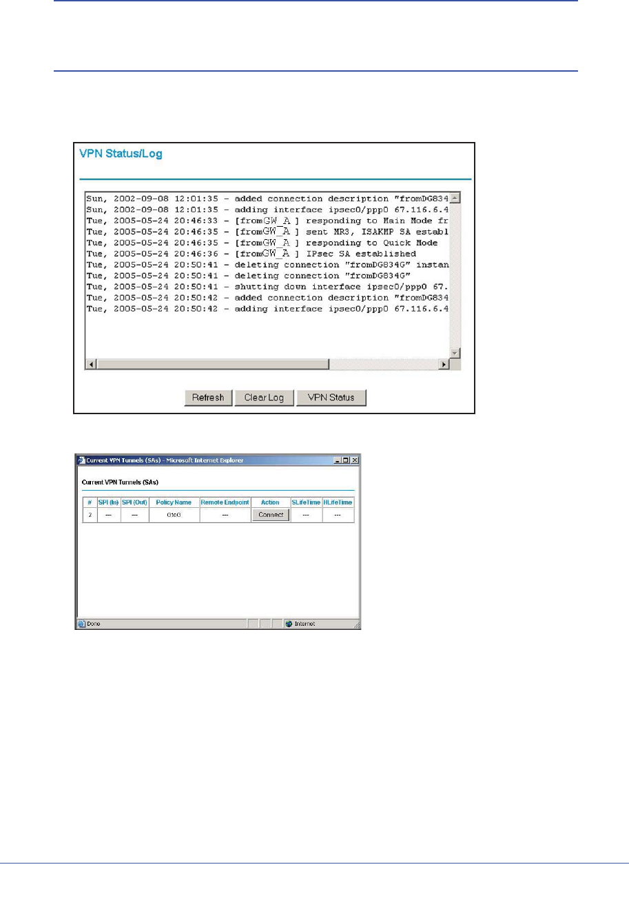
Chapter 7. Virtual Private Networking | 103
N600 Wireless Dual Band Gigabit ADSL2+ Modem Router DGND3700 User Manual
Note: The VPN Status screen is only one of three ways to active a VPN
tunnel. See Activating a VPN Tunnel on page 103 for information
about the other ways.
a. On the wireless modem router menu, select VPN Status. The VPN Status/Log screen
displays:
b. Click the VPN Status button to display the Current VPN Tunnels (SAs) screen:
c. Click Connect for the VPN tunnel you want to activate. View the VPN Status/Log
screen to verify that the tunnel is connected.
VPN Tunnel Control
Activating a VPN Tunnel
There are three ways to activate a VPN tunnel:
•Use the VPN Status screen.
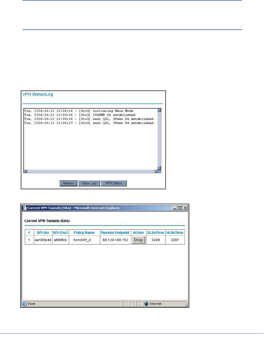
104 | Chapter 7. Virtual Private Networking
N600 Wireless Dual Band Gigabit ADSL2+ Modem Router DGND3700 User Manual
•Activate the VPN tunnel by pinging the remote endpoint.
•Start using the VPN tunnel.
Note: See Using Auto Policy to Configure VPN Tunnels on page 110 for
information about how to enable the IKE keep-alive capability on an
existing VPN tunnel.
Using the VPN Status Screen to Activate a VPN Tunnel
To use the VPN Status screen to activate a VPN tunnel:
1. Log in to the wireless modem router.
2. On the main menu, select VPN Status. The VPN Status/Log screen displays:
3. Click VPN Status to display the Current VPN Tunnels (SAs) screen:
4. Click Connect for the VPN tunnel that you want to activate.
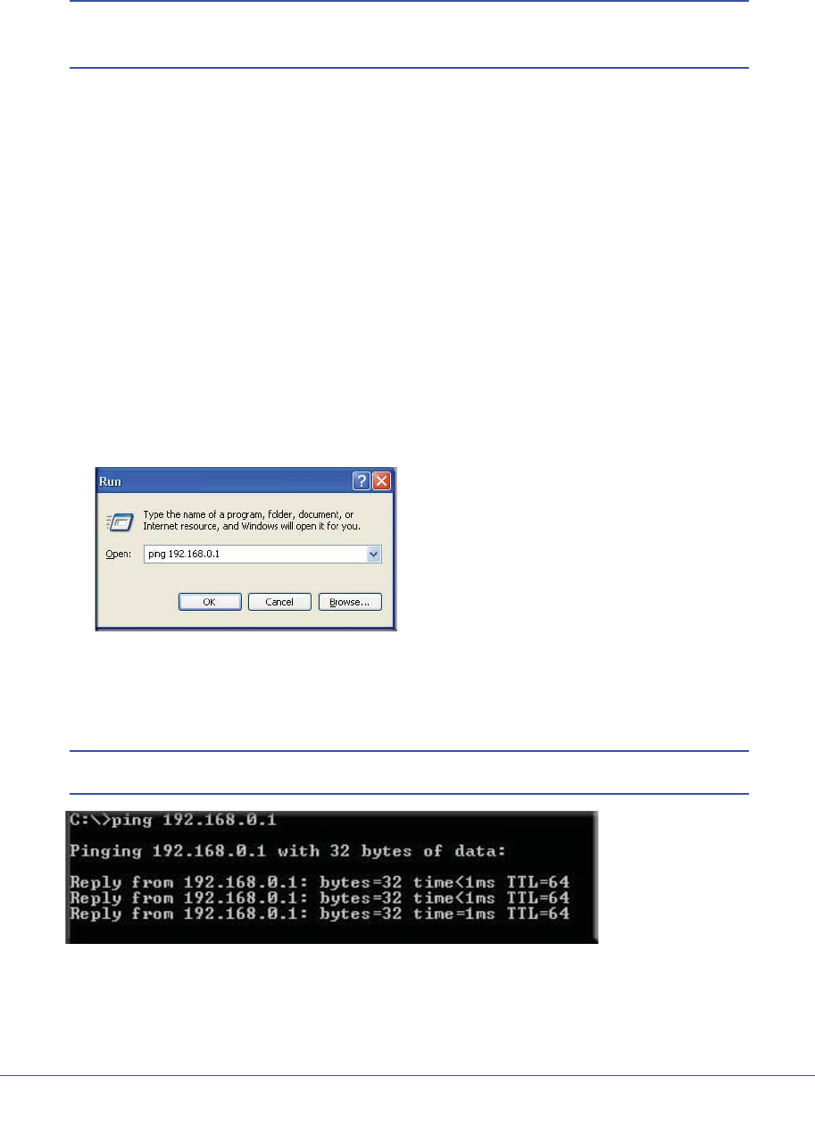
Chapter 7. Virtual Private Networking | 105
N600 Wireless Dual Band Gigabit ADSL2+ Modem Router DGND3700 User Manual
Activating the VPN Tunnel by Pinging the Remote Endpoint
Note: This section uses 192.168.3.1 for a sample remote endpoint LAN IP
address.
To activate the VPN tunnel by pinging the remote endpoint (for example, 192.168.3.1),
perform the following steps depending on whether your configuration is client-to-gateway or
gateway-to-gateway:
•Client-to-gateway configuration. To check the VPN connection, you can initiate a
request from the remote PC to the N600 Wireless Dual Band Gigabit ADSL2+ Modem
Router DGND3700’s network by using the Connect option in the NETGEAR ProSafe
menu bar. The NETGEAR ProSafe client reports the results of the attempt to connect.
Since the remote PC has a dynamically assigned WAN IP address, it must initiate the
request.
To perform a ping test using our example, start from the remote PC:
a. Establish an Internet connection from the PC.
b. On the Windows taskbar, click the Start button, and then select Run.
c. Type ping -t 192.168.3.1, and then click OK.
Running a ping test
to the LAN from the PC
This causes a continuous ping to be sent to the first N600 Wireless Dual Band Gigabit
ADSL2+ Modem Router DGND3700. Within 2 minutes, the ping response should
change from timed out to reply.
Note: You can use Ctrl-C to stop the pinging.
Once the connection is established, you can open a browser on the PC and enter the
LAN IP address of the remote N600 Wireless Dual Band Gigabit ADSL2+ Modem Router
DGND3700. After a short wait, you should see the login screen of the wireless modem
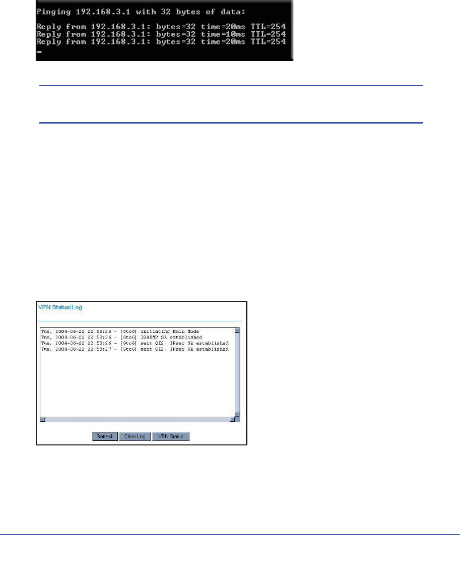
106 | Chapter 7. Virtual Private Networking
N600 Wireless Dual Band Gigabit ADSL2+ Modem Router DGND3700 User Manual
router (unless another PC already has the N600 Wireless Dual Band Gigabit ADSL2+
Modem Router DGND3700 management interface open).
•Gateway-to-gateway configuration. Test the VPN tunnel by pinging the remote network
from a PC attached to Gateway A (the wireless modem router).
a. Open a command prompt (for example, Start > Run > cmd).
b. Type ping 192.168.3.1.
Note: The pings might fail the first time. If they do, then try the pings a
second time.
Start Using a VPN Tunnel to Activate It
To use a VPN tunnel, use a Web browser to go to a URL whose IP address or range is
covered by the policy for that VPN tunnel.
Verifying the Status of a VPN Tunnel
To use the VPN Status screen to determine the status of a VPN tunnel:
1. Log in to the wireless modem router.
2. On the main menu, select VPN Status to display the VPN Status/Log screen.
This log shows the details of recent VPN activity, including the building of the VPN tunnel.
If there is a problem with the VPN tunnel, refer to the log for information about what might
be the cause of the problem.
•Click Refresh to see the most recent entries.
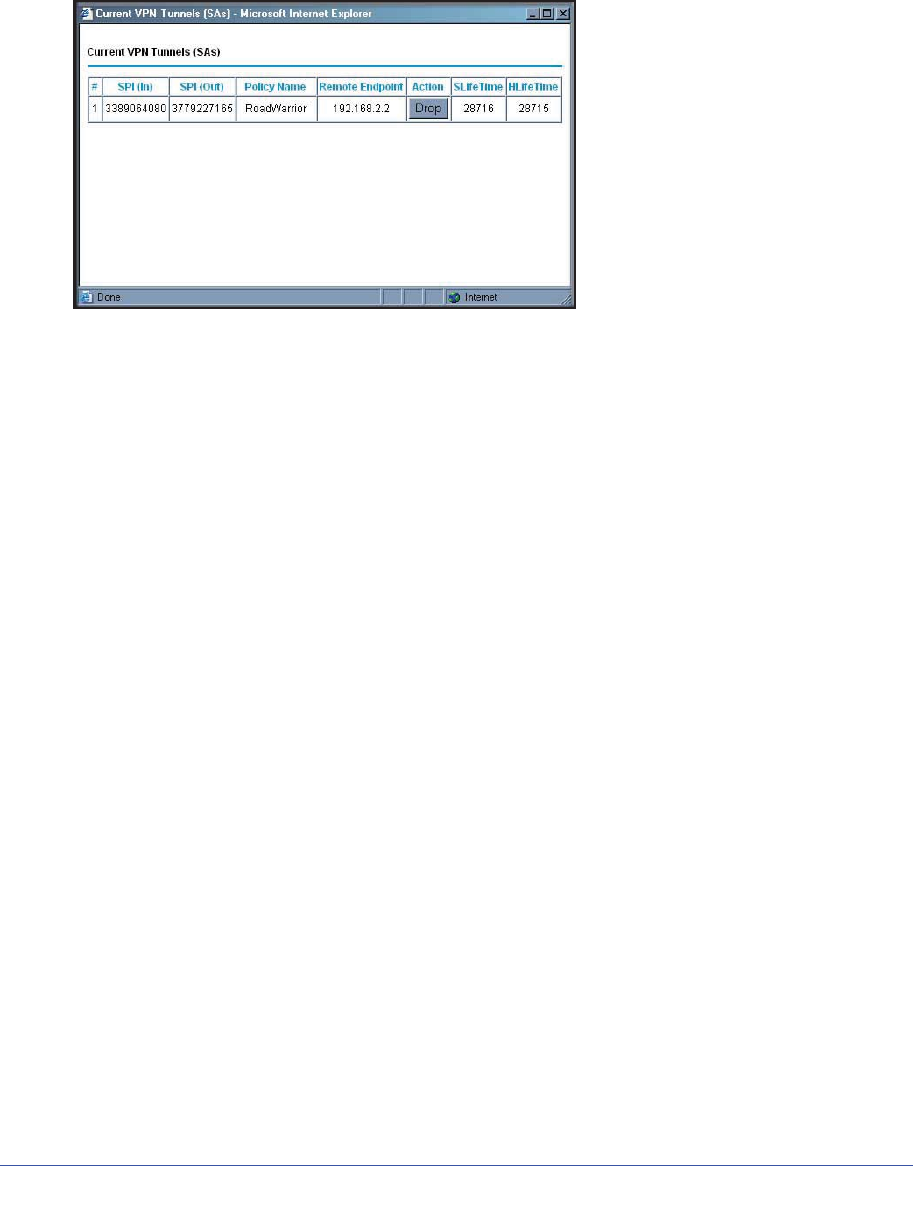
Chapter 7. Virtual Private Networking | 107
N600 Wireless Dual Band Gigabit ADSL2+ Modem Router DGND3700 User Manual
•Click Clear Log to delete all log entries.
3. On the VPN Status/Log screen, click VPN Status to display the Current VPN Tunnels (SAs)
screen.
This table lists the following data for each active VPN tunnel.
•SPI. Each SA has a unique SPI (Security Parameter Index) for traffic in each
direction. For manual key exchange, the SPI is specified in the policy definition. For
automatic key exchange, the SPI is generated by the IKE protocol.
•Policy Name. The VPN policy associated with this SA.
•Remote Endpoint. The IP address on the remote VPN endpoint.
•Action. Either a Drop or a Connect button.
•SLifeTime (Secs). The remaining soft lifetime for this SA in seconds. When the soft
lifetime becomes 0 (zero), the SA (security association) is renegotiated.
•HLifeTime (Secs). The remaining hard lifetime for this SA in seconds. When the hard
lifetime becomes 0 (zero), the SA (security association) is terminated. (It is
reestablished if required.)
Deactivating a VPN Tunnel
Sometimes a VPN tunnel must be deactivated for testing purposes. You can deactivate a
VPN tunnel from two places:
•Policy table on VPN Policies screen
•VPN Status screen
Using the Policy Table on the VPN Policies Screen to Deactivate a VPN Tunnel
To use the VPN Policies screen to deactivate a VPN tunnel:
1. Log in to the wireless modem router.
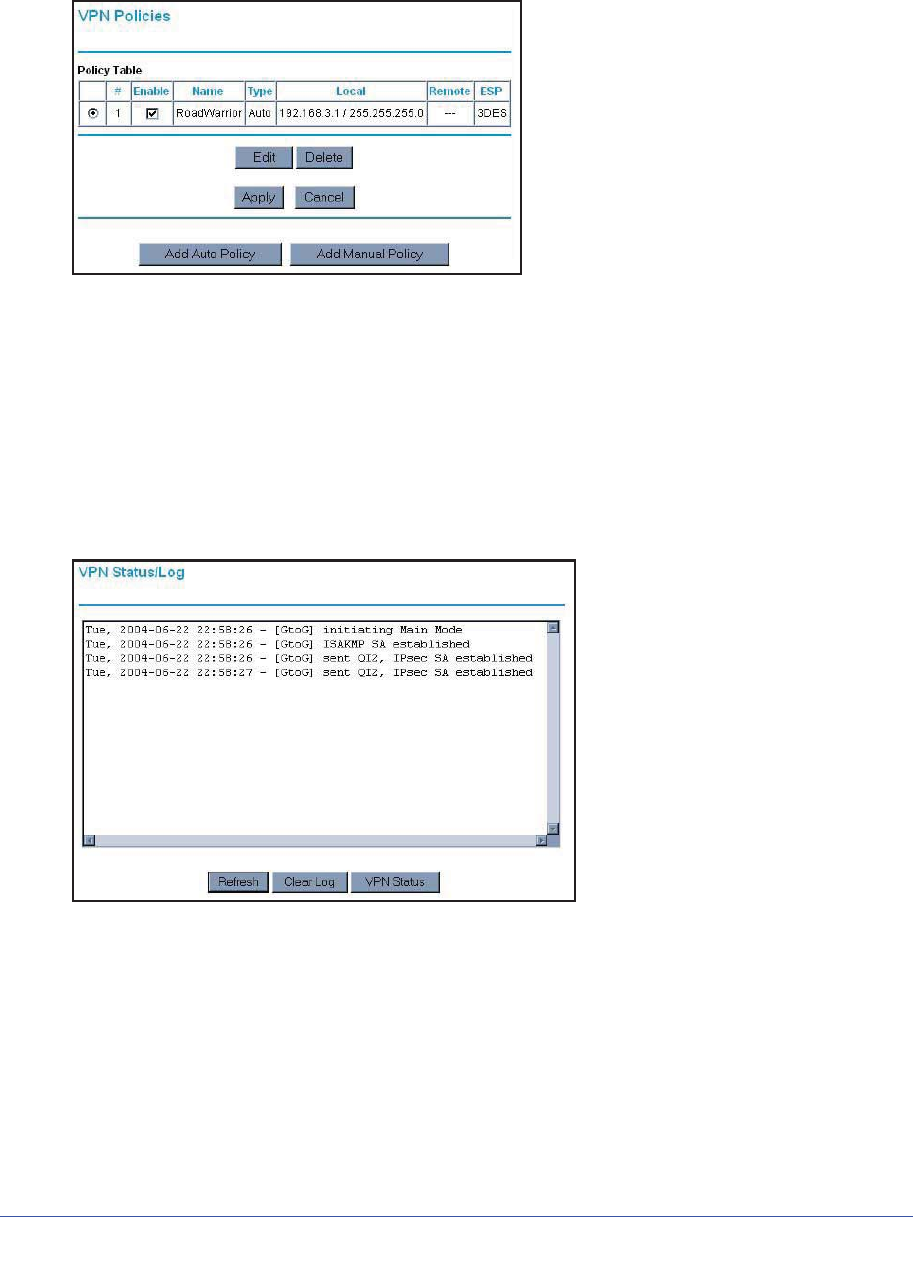
108 | Chapter 7. Virtual Private Networking
N600 Wireless Dual Band Gigabit ADSL2+ Modem Router DGND3700 User Manual
2. On the main menu, select VPN Policies to display the VPN Policies screen.
3. In the Policy Table, clear the Enable check box for the VPN tunnel that you want to
deactivate, and then click Apply. (To reactivate the tunnel, select the Enable check box, and
then click Apply.)
Using the VPN Status Screen to Deactivate a VPN Tunnel
To use the VPN Status screen to deactivate a VPN tunnel:
1. Log in to the wireless modem router.
2. On the main menu, select VPN Policies to display the VPN Policies screen.
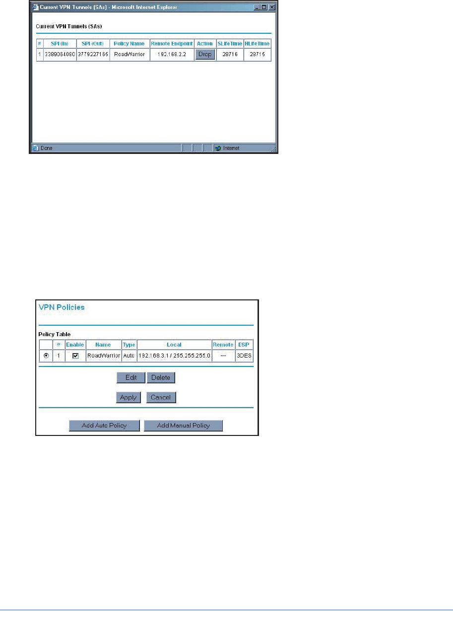
Chapter 7. Virtual Private Networking | 109
N600 Wireless Dual Band Gigabit ADSL2+ Modem Router DGND3700 User Manual
3. Click VPN Status. The Current VPN Tunnels (SAs) screen displays:
4. Click Drop for the VPN tunnel that you want to deactivate.
Deleting a VPN Tunnel
To delete a VPN tunnel:
1. Log in to the wireless modem router.
2. On the main menu, select VPN Policies to display the VPN Policies screen. In the Policy
Table, select the radio button for the VPN tunnel to be deleted, and then click Delete.
Setting Up VPN Tunnels in Special Circumstances
When the VPN Wizard and its VPNC defaults (see Table 16 on page 87) are not appropriate
for your circumstances, use one of these alternatives:
•Auto Policy. For a typical automated Internet Key Exchange (IKE) setup, see Using Auto
Policy to Configure VPN Tunnels on page 110. Auto Policy uses the IKE protocol to
define the authentication scheme and automatically generate the encryption keys.
•Manual Policy. For a manual keying setup in which you must specify each phase of the
connection, see Using Manual Policy to Configure VPN Tunnels on page 117. Manual
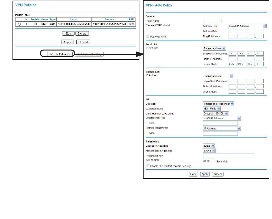
110 | Chapter 7. Virtual Private Networking
N600 Wireless Dual Band Gigabit ADSL2+ Modem Router DGND3700 User Manual
policy does not use IKE. Rather, you manually enter all the authentication and key
parameters. You have more control over the process; however, the process is more
complex, and there are more opportunities for errors or configuration mismatches
between your N600 Wireless Dual Band Gigabit ADSL2+ Modem Router DGND3700 and
the corresponding VPN endpoint gateway or client workstation.
Using Auto Policy to Configure VPN Tunnels
You need to configure matching VPN settings on both VPN endpoints. The outbound VPN
settings on one end must match to the inbound VPN settings on other end, and vice versa.
For an example of using Auto Policy, see Example of Using Auto Policy on page 114.
Configuring VPN Network Connection Parameters
All VPN tunnels on the wireless modem router require that you configure several network
parameters. This section describes those parameters and how to access them.
The most common configuration scenarios use IKE to manage the authentication and
encryption keys. The IKE protocol performs negotiations between the two VPN endpoints to
automatically generate and update the required encryption parameters.
From the main menu, select VPN Policies, and then click the Add Auto Policy button to
display the VPN - Auto Policy screen:

Chapter 7. Virtual Private Networking | 111
N600 Wireless Dual Band Gigabit ADSL2+ Modem Router DGND3700 User Manual
The DGND3700 VPN tunnel network connection fields are defined in the following table.
Table 19. VPN - Auto Policy Screen Settings
Fields and Settings Description
General Policy Name Enter a unique name. This name is not supplied to the remote VPN
endpoint. It is used only to help you manage the policies.
Remote VPN
Endpoint • The remote VPN endpoint must have this VPN’s gateway address
entered as its remote VPN endpoint.
• If the remote endpoint has a dynamic IP address, select Dynamic IP
Address. No address data input is required. You can set up multiple
remote dynamic IP policies, but only one such policy can be enabled
at a time. Otherwise, select an option (IP address or domain name)
and enter the address of the remote VPN endpoint to which you want
to connect.
IKE Keep Alive • If you want to ensure that a connection is kept open, or, if that is not
possible, that it is quickly reestablished when disconnected, select
this check box.
• The ping IP address must be associated with the remote endpoint.
The remote LAN address must be used. This IP address will be
pinged periodically to generate traffic for the VPN tunnel. The remote
keep-alive IP address must be covered by the remote LAN IP range
and must correspond to a device that can respond to ping. The range
should be made as narrow as possible to meet this objective.
Local LAN
The remote VPN
endpoint must
have these IP
addresses entered
as its remote
addresses.
Subnet Mask The network mask.
Single/Start IP
Address • Enter the IP address for a single address, or the starting address for
an address range. A single address setting is used when you want to
make a single server on your LAN available to remote users. A range
must be an address range used on your LAN.
•Any. The remote VPN endpoint can be at any IP address.
Finish IP Address For an address range, enter the finish IP address. This must be an
address range used on your LAN.
Remote LAN
The remote VPN
endpoint must
have these IP
addresses entered
as its local
addresses.
IP Address Single PC - no Subnet. Select this option if there is no LAN (only a
single PC) at the remote endpoint. If this option is selected, no
additional data is required. The typical application is a PC running the
VPN client at the remote end.
Single/Start IP
Address • Enter an IP address that is on the remote LAN. You can use this
setting when you want to access a server on the remote LAN.
• For a range of addresses, enter the starting IP address. This must be
an address range used on the remote LAN.
•Any. Any outgoing traffic from the computers in the Local IP fields
triggers an attempted VPN connection to the remote VPN endpoint.
Be sure you want this option before selecting it.
Finish IP Address Enter the finish IP address for a range of addresses. This must be an
address range used on the remote LAN.
Subnet Mask Enter the network mask.

112 | Chapter 7. Virtual Private Networking
N600 Wireless Dual Band Gigabit ADSL2+ Modem Router DGND3700 User Manual
IKE Direction This setting is used when the router determines if the IKE policy
matches the current traffic. Select an option.
•Responder only. Incoming connections are allowed, but outgoing
connections are blocked.
•Initiator and Responder. Both incoming and outgoing connections
are allowed.
Exchange Mode Ensure that the remote VPN endpoint is set to use Main Mode.
Diffie-Hellman
(DH) Group The Diffie-Hellman algorithm is used when keys are exchanged. The
DH Group setting determines the bit size used in the exchange. This
value must match the value used on the remote VPN gateway.
Local Identity Type Select an option to match the Remote Identity Type setting on the
remote VPN endpoint.
•WAN IP Address. Your Internet IP address.
•Fully Qualified Domain Name. Your domain name.
•Fully Qualified User Name. Your name, email address, or other ID.
Local Identity Data Enter the data for the local identity type that you selected. (If WAN IP
Address is selected, no input is required.)
Remote Identity
Type Select the option that matches the Local Identity Type setting on the
remote VPN endpoint.
•IP Address. The Internet IP address of the remote VPN endpoint.
•Fully Qualified Domain Name. The domain name of the remote
VPN endpoint.
•Fully Qualified User Name. The name, email address, or other ID of
the remote VPN endpoint.
Remote Identity
Data Enter the data for the remote identity type that you selected. If IP
Address is selected, no input is required.
Parameters Encryption
Algorithm The encryption algorithm used for both IKE and IPSec. This setting
must match the setting used on the remote VPN gateway. DES and
3DES are supported.
•DES. The Data Encryption Standard (DES) processes input data that
is 64 bits wide, encrypting these values using a 56-bit key. Faster but
less secure than 3DES.
•3DES. (Triple DES) achieves a higher level of security by encrypting
the data three times using DES with three different, unrelated keys.
Authentication
Algorithm The authentication algorithm used for both IKE and IPSec. This setting
must match the setting used on the remote VPN gateway. Auto, MD5,
and SHA-1 are supported. Auto negotiates with the remote VPN
endpoint and is not available in responder-only mode.
•MD5. 128 bits, faster but less secure.
•SHA-1. 160 bits, slower but more secure. This is the default.
Pre-shared Key The key must be entered both here and on the remote VPN gateway.
Table 19. VPN - Auto Policy Screen Settings (Continued)
Fields and Settings Description

Chapter 7. Virtual Private Networking | 113
N600 Wireless Dual Band Gigabit ADSL2+ Modem Router DGND3700 User Manual
Parameters
(Continued) SA Life Time The time interval before the SA (security association) expires. (It is
automatically reestablished as required.) While using a short time
period (or data amount) increases security, it also degrades
performance. It is common to use periods over an hour (3600 seconds)
for the SA life-time. This setting applies to both IKE and IPSec SAs.
Enable IPSec PFS
(Perfect Forward
Secrecy)
• If this check box is selected, security is enhanced by ensuring that
the key is changed at regular intervals. Also, even if one key is
broken, subsequent keys are no easier to break. (Each key has no
relationship to the previous key.)
• This setting applies to both IKE and IPSec SAs. When configuring
the remote endpoint to match this setting, you might have to specify
the key group used. For this device, the key group is the same as the
DH Group setting in the IKE section.
General Policy Name Enter a unique name to identify this policy. This name is not supplied to
the remote VPN endpoint. It is used only to help you manage the
policies.
Remote VPN
Endpoint • The remote VPN endpoint must have this VPN gateway's address
entered as its remote VPN endpoint.
• If the remote endpoint has a dynamic IP address, select Dynamic IP
address. No address data input is required. You can set up multiple
remote dynamic IP policies, but only one such policy can be enabled
at a time. Otherwise, select an option (IP address or domain name)
and enter the address of the remote VPN endpoint to which you want
to connect.
IKE Keep Alive • If you want to ensure that a connection is kept open, or, if that is not
possible, that it is quickly reestablished when disconnected, select
this check box.
• The ping IP address must be associated with the remote endpoint.
The remote LAN address must be used. This IP address will be
pinged periodically to generate traffic for the VPN tunnel. The remote
keep-alive IP address must be covered by the remote LAN IP range
and must correspond to a device that can respond to ping. The range
should be made as narrow as possible to meet this objective.
Local LAN
The remote VPN
endpoint must
have these IP
addresses entered
as its remote
addresses.
Subnet Mask Enter the network mask.
Single/Start IP
Address • Enter the IP address for a single address, or the starting address for
an address range. A single address setting is used when you want to
make a single server on your LAN available to remote users. A range
must be an address range used on your LAN.
•Any. The remote VPN endpoint might be at any IP address.
Table 19. VPN - Auto Policy Screen Settings (Continued)
Fields and Settings Description
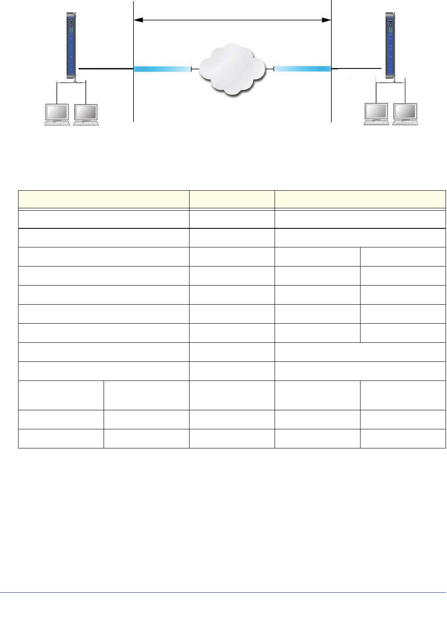
114 | Chapter 7. Virtual Private Networking
N600 Wireless Dual Band Gigabit ADSL2+ Modem Router DGND3700 User Manual
Example of Using Auto Policy
VPN Tunnel
Internet
Gateway A Gateway B
22.23.24.25
14.15.16.17
IP: 192.168.0.1 IP:192.168.3.1
Figure 46.
The following settings are assumed for this example:
Table 20. Gateway-to-Gateway VPN Tunnel Configuration Worksheet
Parameter Value to Be Entered Field Selection
Connection Name GtoG N/A
Pre-Shared Key 12345678 N/A
Secure Association N/A Main Mode Manual Keys
Perfect Forward secrecy N/A Enabled Disabled
Encryption Protocol N/A DES 3DES
Authentication Protocol N/A MD5 SHA-1
Diffie-Hellman (DH) Group N/A Group 1 Group 2
Key Life in seconds 28800 (8 hours) N/A
IKE Life Time in seconds 3600 (1 hour) N/A
VPN Endpoint Local IPSecID LAN IP Address Subnet Mask FQDN or Gateway
IP (WAN IP Address
Gateway_A GW_A 192.168.0.1 255.255.255.0 14.15.16.17
Gateway_B GW_B 192.168.3.1 255.255.255.0 22.23.24.25
To use Auto Policy:
1. Set the LAN IPs on each wireless modem router to different subnets and configure each
correctly for the Internet. On the main menu, select VPN Policies and click the Add
Auto Policy button.
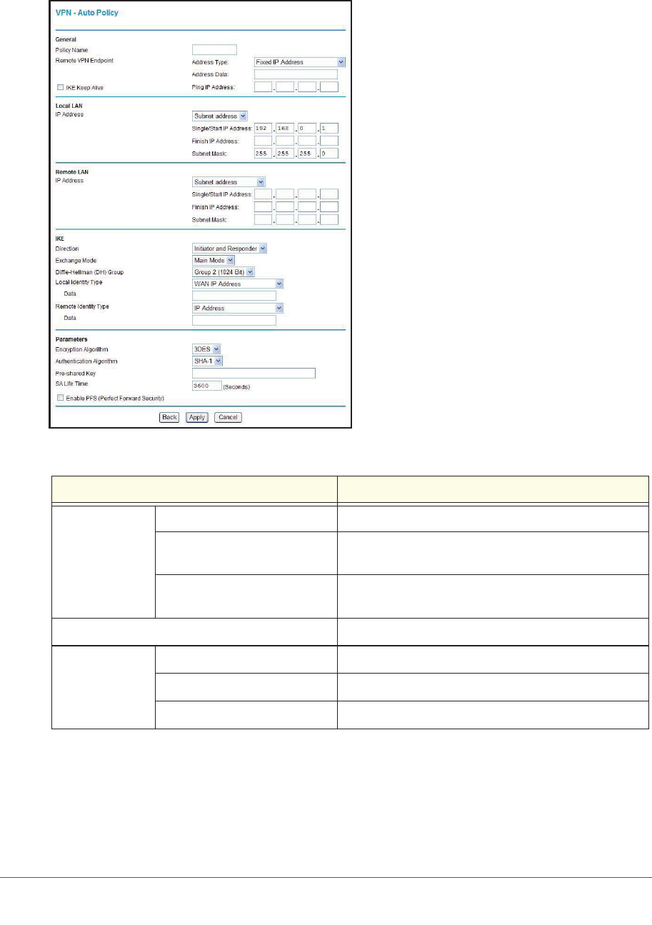
Chapter 7. Virtual Private Networking | 115
N600 Wireless Dual Band Gigabit ADSL2+ Modem Router DGND3700 User Manual
The VPN Auto Policy screen displays:
2. Enter these policy settings:
Auto Policy Field Description
General Policy Name GtoG
Remote VPN Endpoint
Address Type Fixed
Remote VPN Endpoint
Address Data 22.23.24.25
Local LAN Use the default settings.
Remote LAN IP Address Select Subnet address from the drop-down list.
Start IP Address 192.168.3.1
Subnet Mask 255.255.255.0
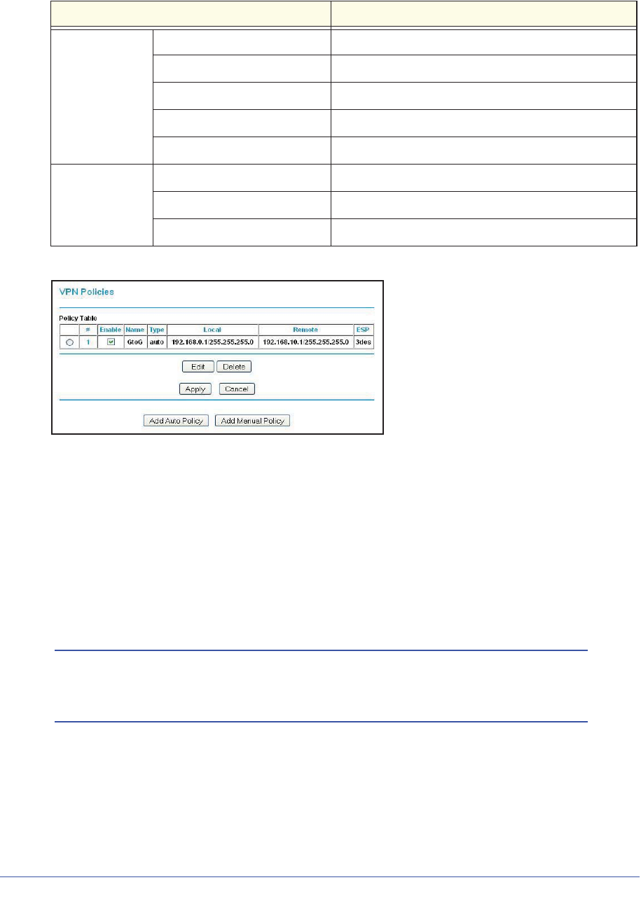
116 | Chapter 7. Virtual Private Networking
N600 Wireless Dual Band Gigabit ADSL2+ Modem Router DGND3700 User Manual
3. Click Apply. The VPN Policies screen displays:
4. Repeat these steps for the N600 Wireless Dual Band Gigabit ADSL2+ Modem Router
DGND3700 on LAN B. Pay special attention to the following network settings:
•General, Remote Address Data (for example, 14.15.16.17)
•Remote LAN, Start IP Address
-IP Address (for example, 192.168.0.1)
-Subnet Mask (for example, 255.255.255.0)
-Pre-shared Key (for example, 12345678)
5. Use the VPN Status screen to activate the VPN tunnel:
Note: The VPN Status screen is only one of three ways to active a VPN
tunnel. See Activating a VPN Tunnel on page 103 for information
about the other ways.
IKE Direction Initiator and Responder
Exchange Mode Main Mode
Diffie-Hellman (DH) Group Group 2 (1024 Bit)
Local Identity Type Use the default setting.
Remote Identity Type Use the default setting.
Parameters Encryption Algorithm 3DES
Authentication Algorithm MD5
Pre-shared Key 12345678
Auto Policy Field Description
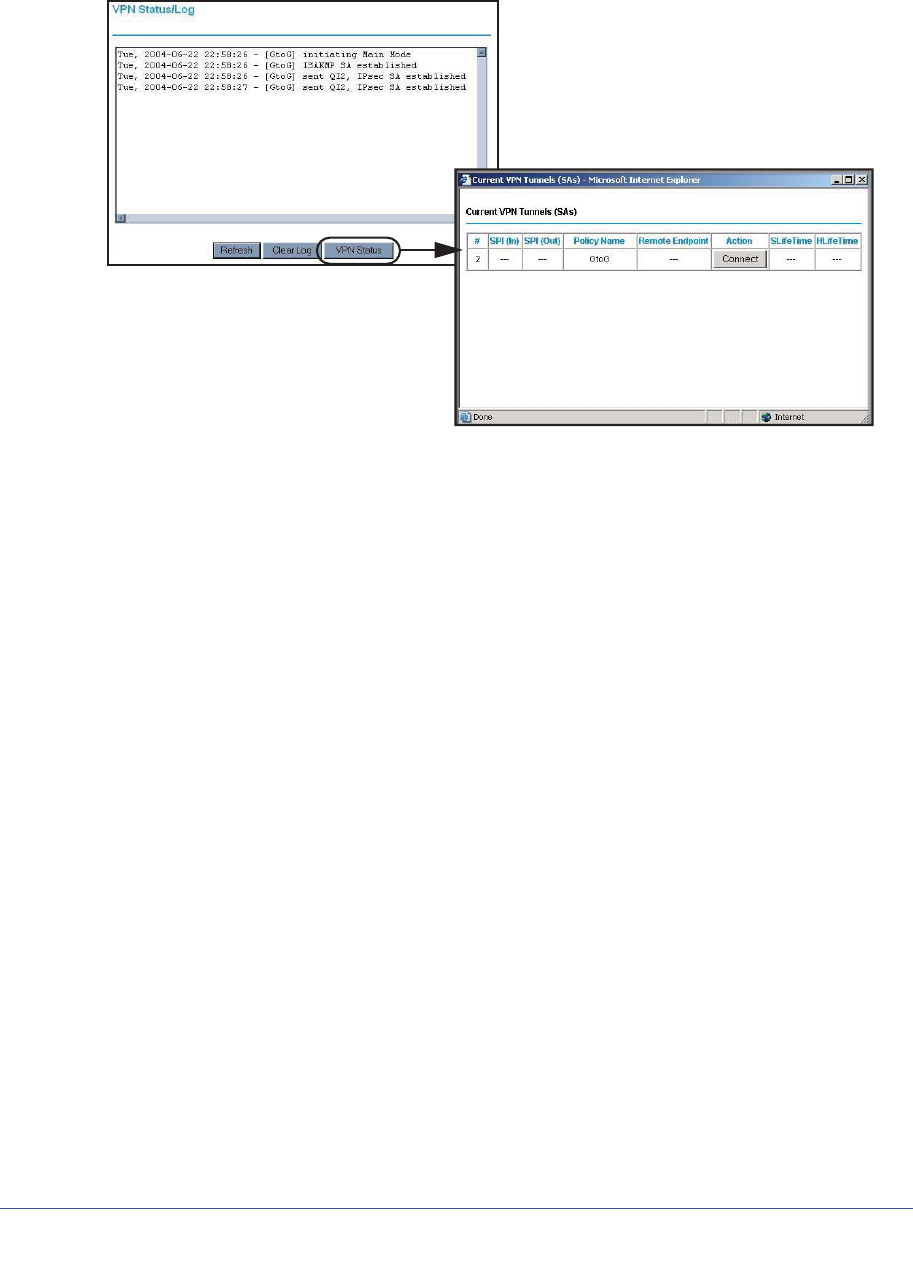
Chapter 7. Virtual Private Networking | 117
N600 Wireless Dual Band Gigabit ADSL2+ Modem Router DGND3700 User Manual
a. From the main menu, select VPN Status to display the VPN Status/Log screen. Then
click VPN Status to display the Current VPN Tunnels (SAs) screen:
b. Click Connect for the VPN tunnel that you want to activate. Review the VPN
Status/Log screen (Figure a on page 103) to verify that the tunnel is connected.
Using Manual Policy to Configure VPN Tunnels
As an alternative to IKE, you can use manual keying, in which you must specify each phase
of the connection. A manual VPN policy requires all settings for the VPN tunnel to be
manually input at each end (both VPN endpoints).
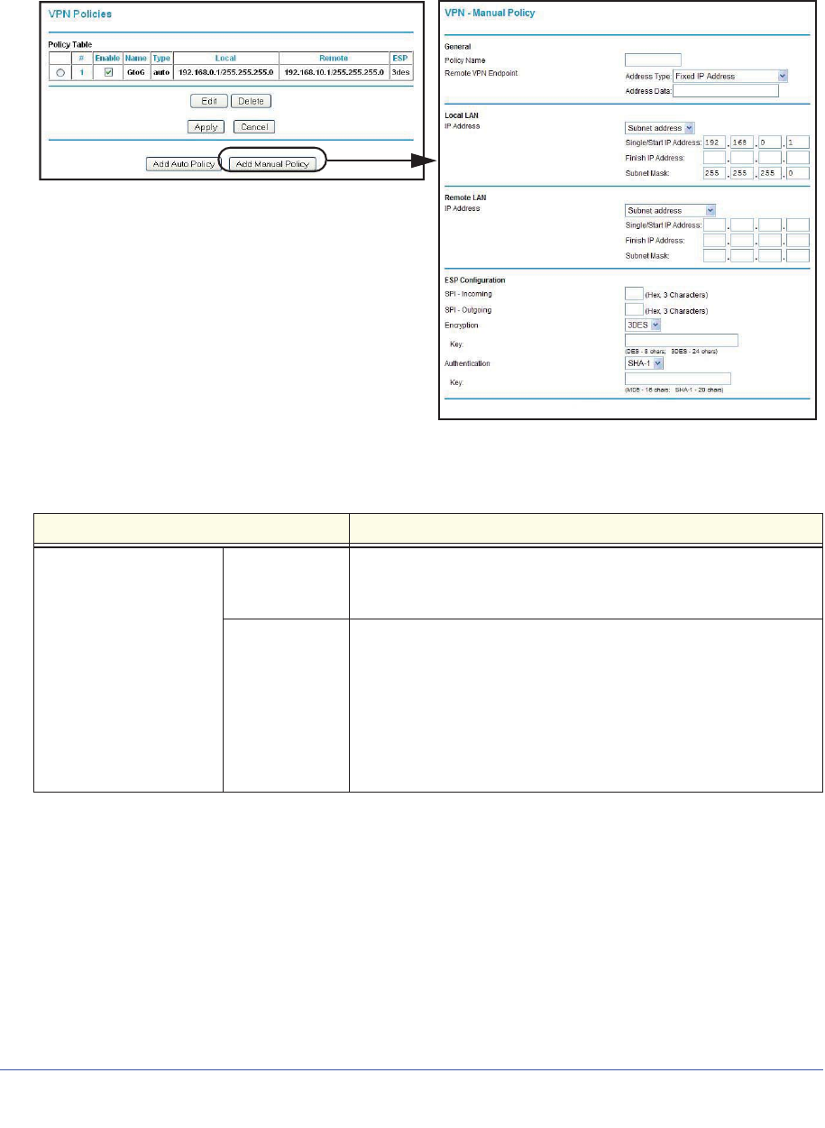
118 | Chapter 7. Virtual Private Networking
N600 Wireless Dual Band Gigabit ADSL2+ Modem Router DGND3700 User Manual
On the main menu, select VPN Policies, and then click the Add Manual Policy radio button
to display the VPN - Manual Policy screen:
The following table explains the fields in the VPN - Manual Policy screen.
Table 21. VPN Manual Policy Fields and Settings
Fields and Settings Description
General
The N600 Wireless Dual
Band Gigabit ADSL2+
Modem Router
DGND3700 VPN tunnel
network connection
fields.
Policy Name Enter a unique name to identify this policy. This name is not
supplied to the remote VPN endpoint. It is used only to help you
manage the policies.
Remote VPN
Endpoint • The remote VPN endpoint must have this VPN’s gateway
address entered as its remote VPN endpoint.
• If the remote endpoint has a dynamic IP address, select
Dynamic IP Address. No address data input is required. You
can set up multiple remote dynamic IP policies, but only one
such policy can be enabled at a time. Otherwise, select an
option (IP address or domain name) and enter the address of
the remote VPN endpoint to which you want to connect.

Chapter 7. Virtual Private Networking | 119
N600 Wireless Dual Band Gigabit ADSL2+ Modem Router DGND3700 User Manual
Local LAN IP Address
The remote VPN
endpoint must have
these IP addresses
entered as its remote
addresses.
Subnet Mask Enter the network mask.
Single PC - no
Subnet Select this option if there is no LAN (only a single PC) at the
remote endpoint. If this option is selected, no additional data is
required.
Single/Start IP
Address • The IP address for a single address, or the starting address for
an address range used on the LAN. If you want to make a single
server on your LAN available to remote users, use a single
address settings.
•Any. The remote VPN endpoint can be at any IP address.
Finish IP
Address For an address range, enter the finish IP address. This must be an
address range used on your LAN.
Subnet Mask Enter the network mask.
Remote LAN IP Address
The remote VPN
endpoint must have
these IP addresses
entered as its local
addresses.
IP Address Single PC - no Subnet. Select this option if there is no LAN (only
a single PC) at the remote endpoint. If this option is selected, no
additional data is required. The typical application is a PC running
the VPN client at the remote end.
Single/Start IP
Address • Enter an IP address on the remote LAN. You can use this setting
to access a server.
• For a range of addresses, enter the starting IP address. This
must be an address range used on the remote LAN.
•Any. Any outgoing traffic from specified Local IP computers
triggers an attempted VPN connection to the remote VPN
endpoint. Be sure you want this option before selecting it.
Finish IP
Address Enter the finish IP address for a range of addresses. This must be
an address range used on the remote LAN.
Subnet Mask Enter the network mask.
ESP Configuration
ESP (Encapsulating
Security Payload)
provides security for the
payload (data) sent
through the VPN tunnel.
SPI Enter the required Security Policy Indexes (SPIs). Each policy
must have unique SPIs. These settings must match the remote
VPN endpoint. The in setting here must match the out setting on
the remote VPN endpoint, and the out setting here must match the
in setting on the remote VPN endpoint.
Encryption Select an encryption algorithm, and enter the key in the field
provided. For 3DES, the keys should be 24 ASCII characters, and
for DES, the keys should be 8 ASCII characters.
•DES. The Data Encryption Standard (DES) processes input data
that is 64 bits wide, encrypting these values using a 56-bit key.
Faster but less secure than 3DES.
•3DES. (Triple DES) achieves a higher level of security by
encrypting the data three times using DES with three different,
unrelated keys.
Authentication
Table 21. VPN Manual Policy Fields and Settings (Continued)
Fields and Settings Description

Chapter 8. Advanced Settings | 120
8
8. Advanced Settings
Configuring for unique situations
This chapter describes the advanced features of your wireless modem router. The information is
for users with a solid understanding of networking concepts who want to set the router up for
unique situations such as when remote access from the Internet by IP or domain name is
needed.
This chapter contains the following sections:
•WAN Setup
•Dynamic DNS
•LAN Setup
•Setting Up Quality of Service (QoS)
•Advanced Wireless Settings
•Building Wireless Bridging and Repeating Networks
•Remote Management
•Static Routes
•Universal Plug and Play
•Advanced USB Settings
•Traffic Meter
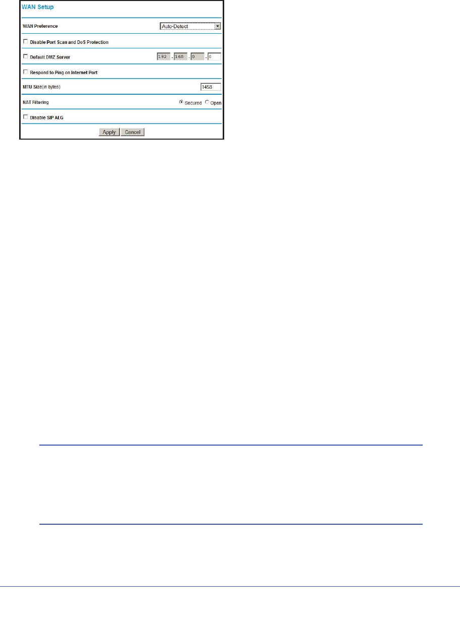
Chapter 8. Advanced Settings | 121
N600 Wireless Dual Band Gigabit ADSL2+ Modem Router DGND3700 User Manual
WAN Setup
Select Advanced > WAN Setup to display the following screen:
Figure 47. WAN Setup screen
WAN Preference
Configure whether the wireless modem router uses only one WAN port exclusively (either
ADSL WAN or Ethernet WAN) or detects automatically the WAN port to use.
Disable Port Scan and DOS Protection
The firewall protects your LAN against port scans and denial of service (DOS) attacks. This
protection should be disabled only in special circumstances.
Default DMZ Server
The default demilitarized zone (DMZ) server feature is helpful when you use online games
and video conferencing applications that are incompatible with NAT. The wireless modem
router is programmed to recognize some of these applications and to work correctly with
them, but there are other applications that might not function well. In some cases, one local
computer can run the application correctly if that computer’s IP address is entered as the
default DMZ server.
Note: For security reasons, you should avoid using the default DMZ server
feature. When a computer is designated as the default DMZ server,
it loses much of the protection of the firewall and is exposed to many
exploits from the Internet. If compromised, the computer can be
used to attack your network.
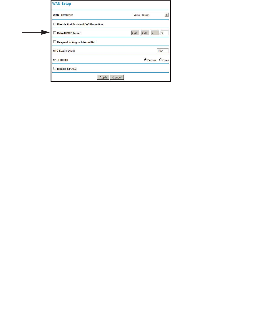
122 | Chapter 8. Advanced Settings
N600 Wireless Dual Band Gigabit ADSL2+ Modem Router DGND3700 User Manual
Incoming traffic from the Internet is usually discarded by the wireless modem router unless
the traffic is a response to one of your local computers or a service that you have configured
in the Ports screen. Instead of discarding this traffic, you can have it forwarded to one
computer on your network. This computer is called the default DMZ server.
To assign a computer or server to be a default DMZ server:
1. In the WAN screen, select the Default DMZ Server check box.
Figure 48. Default DMZ Server setting
2. Type the IP address for that server and click Apply.
Respond To Ping On Internet Port
If you want the wireless modem router to respond to a ping from the Internet, select this
check box. This should be used only as a diagnostic tool, because it allows your wireless
modem router to be discovered, which can be a security problem. Do not select this check
box unless you have a specific reason to do so.
MTU Size (in bytes)
The normal Maximum Transmit Unit (MTU) value for most Ethernet networks is 1500 bytes,
1492 Bytes for PPPoE connections, and 1458 for PPPoA connections. For some ISPs you
may need to reduce the MTU. But this is rarely required, and should not be done unless you
are sure it is necessary for your ISP connection.
NAT Filtering
This option determines how the router deals with inbound traffic. The Secured option
provides a secured firewall to protect the PCs on LAN from attacks from the Internet, but it
may cause some Internet games, point-to-point applications, and multimedia applications
unable to work. The Open option, on the other hand, provides a much less secured firewall,
while it allows almost all Internet applications to work.
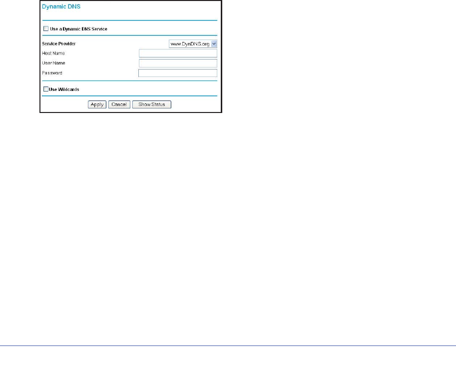
Chapter 8. Advanced Settings | 123
N600 Wireless Dual Band Gigabit ADSL2+ Modem Router DGND3700 User Manual
Disable SIP ALG
The Session Initiation Protocol (SIP) Application Level Gateway (ALG) is enabled by default
to optimize VoIP phone calls that use the SIP. The Disable SIP ALG check box allows you to
disable the SIP ALG. Disabling the SIP ALG might be useful when running certain
applications.
Dynamic DNS
If your network has a permanently assigned IP address, you can register a domain name and
have that name linked with your IP address by public Domain Name Servers (DNS).
However, if your Internet account uses a dynamically assigned IP address, you do not know
in advance what your IP address is, and the address can change frequently. In this case, use
a commercial Dynamic DNS service that lets you register your domain to its IP address and
forwards traffic directed at your domain to your frequently changing IP address.
The router has a client that can connect to a Dynamic DNS service provider. Once you have
configured your ISP account information in the router, whenever your ISP-assigned IP
address changes, your router contacts your Dynamic DNS service provider, logs in to your
account, and registers your new IP address.
1. Select Advanced > Dynamic DNS to display the following screen.
Figure 49. Dynamic DNS screen
2. Access the website of one of the Dynamic DNS service providers whose names appear in
the Service Provider drop-down list, and register for an account. For example, for
dyndns.org, go to www.dyndns.org.
3. Select the Use a Dynamic DNS Service check box.
4. Select the name of your Dynamic DNS service provider.
5. Type the host name that your Dynamic DNS service provider gave you. The Dynamic DNS
service provider might call this the domain name. If your URL is myName.dyndns.org, then
your host name is myName.
6. Type the user name for your Dynamic DNS account.
7. Type the password (or key) for your Dynamic DNS account.
8. If your Dynamic DNS provider allows the use of wildcards in resolving your URL, you can
select the Use Wildcards check box to activate this feature. For example, the wildcard
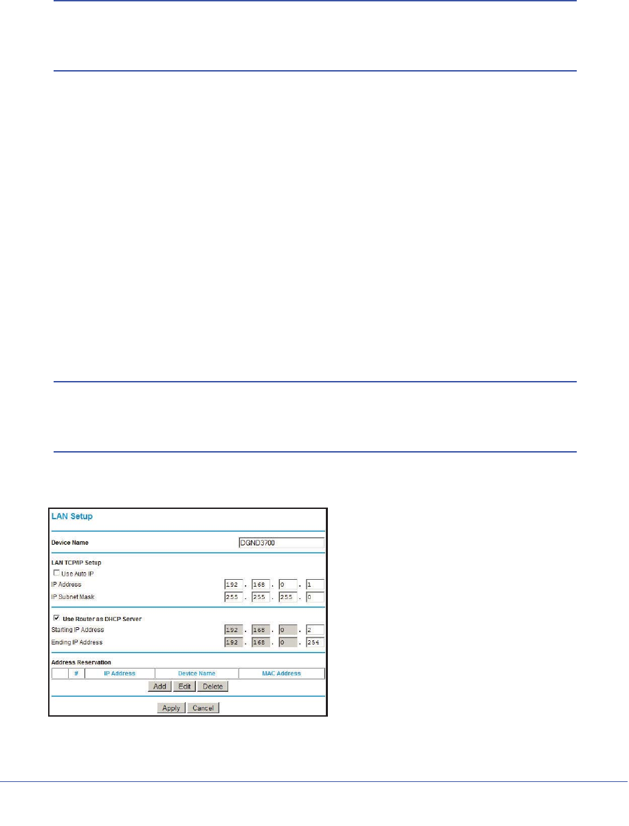
124 | Chapter 8. Advanced Settings
N600 Wireless Dual Band Gigabit ADSL2+ Modem Router DGND3700 User Manual
feature causes *.yourhost.dyndns.org to be aliased to the same IP address as
yourhost.dyndns.org.
9. Click Apply to save your settings.
Note: If your ISP assigns a private WAN IP address such as 192.168.x.x
or 10.x.x.x, the Dynamic DNS service will not work because private
addresses are not routed on the Internet.
LAN Setup
The LAN Setup screen allows configuration of LAN IP services such as DHCP and Routing
Information Protocol (RIP). The wireless modem router is shipped preconfigured to use
private IP addresses on the LAN side and to act as a DHCP server. The wireless modem
router’s default LAN IP configuration is as follows:
•LAN IP address. 192.168.0.1
•Subnet mask. 255.255.255.0
These addresses are part of the private address range designated by the Internet
Engineering Task Force (IETF http://www.ietf.org/) for use in private networks, and should be
suitable in most applications. If your network has a requirement to use a different IP
addressing scheme, you can make those changes in the LAN IP Setup screen.
Note: If you change the LAN IP address of the wireless modem router
while connected through the browser, you are disconnected. To
reconnect, open a new connection to the new IP address and log in.
1. Select Advanced > LAN Setup.
Figure 50. LAN Setup screen

Chapter 8. Advanced Settings | 125
N600 Wireless Dual Band Gigabit ADSL2+ Modem Router DGND3700 User Manual
2. Enter the LAN Setup configuration and click Apply to save your changes.
Note: The default DHCP and TCP/IP values work for most users.
Device Name
This is an abbreviated name of the wireless modem router. You see this name for the router
in Network Explorer on Windows systems.
Use Auto IP
Select this check box if you want the wireless modem router to set up the LAN IP addresses
automatically.
IP Address
The LAN IP address of the wireless modem router.
IP Subnet Mask
The LAN subnet mask of the wireless modem router. Combined with the IP address, the IP
subnet mask allows a device to know which other addresses are local to it, and which have to
be reached through a gateway or wireless modem router.
Use Router as DHCP Server
By default, the wireless modem router functions as a Dynamic Host Configuration Protocol
(DHCP) server, allowing it to assign IP, DNS server, and default gateway addresses to all
computers connected to the wireless modem router’s LAN. The assigned default gateway
address is the LAN address of the router. IP addresses are assigned to the attached PCs
from a pool of addresses specified in this screen. Each pool address is tested before it is
assigned to avoid duplicate addresses on the LAN.
For most applications, the default DHCP and TCP/IP settings of the router are satisfactory.
Reserved IP Addresses Setup
When you specify a reserved IP address for a computer on the LAN, that computer always
receives the same IP address each time it accesses the router’s DHCP server. Reserved IP
addresses should be assigned to servers that require permanent IP settings.
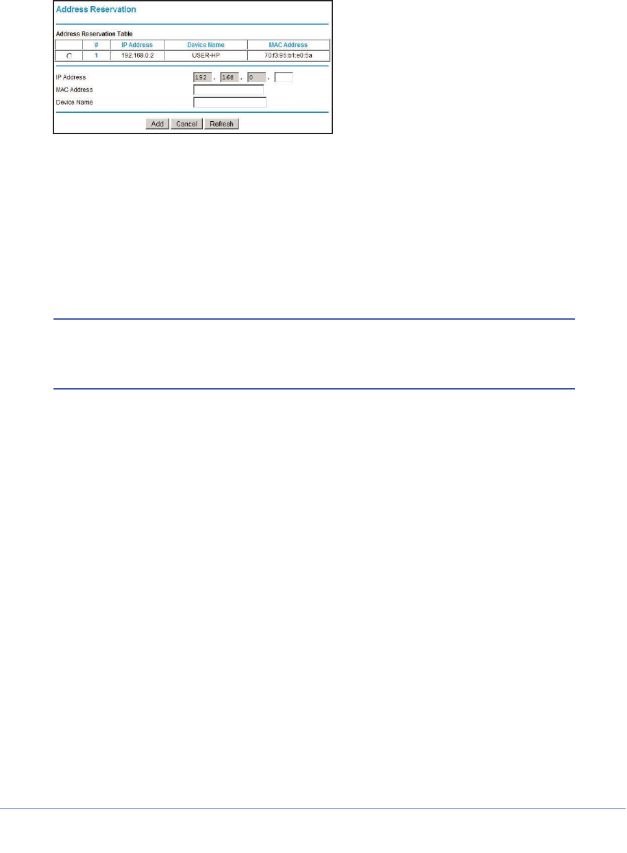
126 | Chapter 8. Advanced Settings
N600 Wireless Dual Band Gigabit ADSL2+ Modem Router DGND3700 User Manual
To reserve an IP address:
1. Select Advanced > LAN Setup and click the Add button.
2. In the IP Address field, type the IP address to assign to the computer or server. Choose an
IP address from the router’s LAN subnet, such as 192.168.0.x.
3. Type the MAC address of the computer or server.
Tip: If the computer is already present on your network, copy its MAC
address from the Attached Devices screen and paste it here.
4. Click Apply to enter the reserved address into the table.
Note: The reserved address is not assigned until the next time the
computer contacts the router’s DHCP server. Reboot the computer
or access its IP configuration to force a DHCP release and renew.
To edit or delete a reserved address entry:
1. Click the button next to the reserved address that you want to edit or delete.
2. Click Edit or Delete.
Setting Up Quality of Service (QoS)
Quality of Service (QoS) is an advanced feature that can be used to prioritize some types of
traffic ahead of others. The modem router can provide QoS prioritization over the wireless
link and on the Internet connection.
The modem router supports Wi-Fi Multimedia Quality of Service (WMM QoS) to prioritize
wireless voice and video traffic over the wireless link. WMM QoS provides prioritization of
wireless data packets from different applications based on four access categories: voice,
video, best effort, and background. For an application to receive the benefits of WMM QoS,
both it and the client running that application must be WMM enabled. Legacy applications
that do not support WMM, and applications that do not require QoS, are assigned to the best
effort category, which receives a lower priority than voice and video.
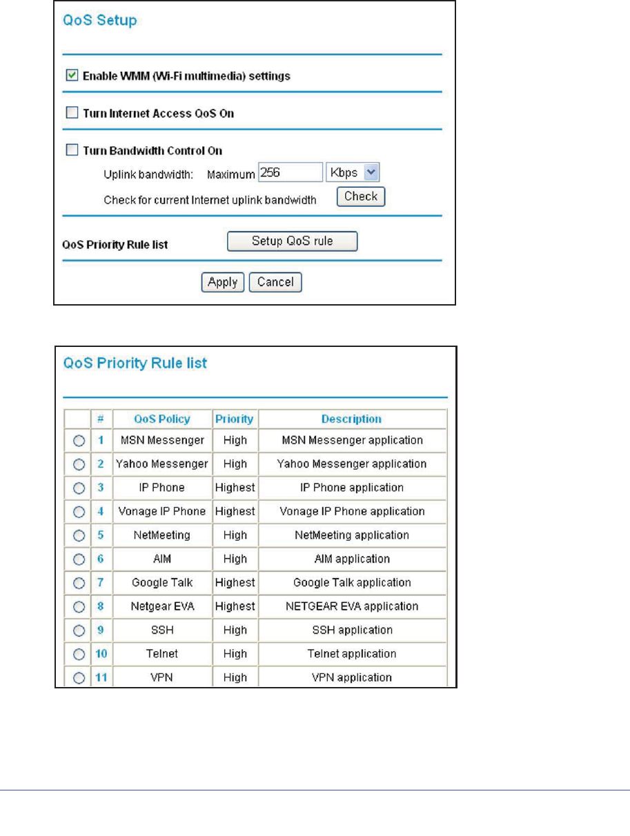
Chapter 8. Advanced Settings | 127
N600 Wireless Dual Band Gigabit ADSL2+ Modem Router DGND3700 User Manual
Configuring QoS for Internet Access
To specify prioritization of traffic, you must add or create a policy for the type of traffic.
1. From the main menu, under Advanced, select QoS Setup.
2. Click Setup QoS rule. The QoS Priority Rule list displays:
3. To change a rule, select its radio button.
4. Scroll down to the bottom of the screen:
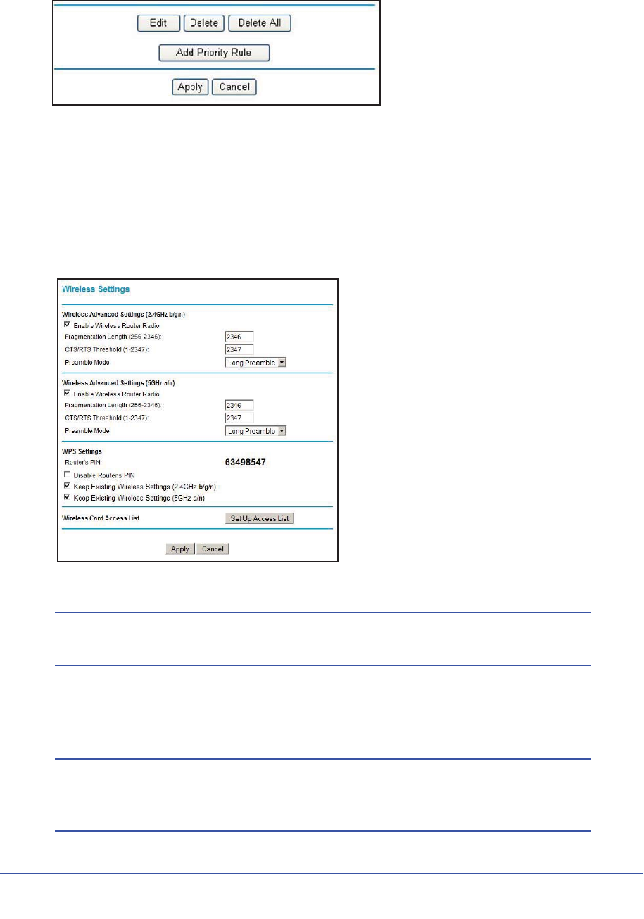
128 | Chapter 8. Advanced Settings
N600 Wireless Dual Band Gigabit ADSL2+ Modem Router DGND3700 User Manual
5. To edit a rule, click Edit. to add a custom rule, click Add Priority Rule.
6. Click Apply to save this rule to the QoS Policy list and return to the QoS Setup screen.
7. In the QoS Setup screen, click Apply.
Advanced Wireless Settings
1. Select Advanced > Wireless Settings to display the following screen:
Figure 51. Advanced Wireless Settings screen
Note: The advanced WPS settings section is not displayed if you selected
WEP as the security option.
2. If you make changes, click Apply. Note that the WLAN settings come from the settings you
made in the Wireless Settings Screen on page 41).
Note: The wireless router is already configured with the optimum settings.
Do not alter these settings unless directed by NETGEAR support.
Incorrect settings might disable the wireless router unexpectedly.

Chapter 8. Advanced Settings | 129
N600 Wireless Dual Band Gigabit ADSL2+ Modem Router DGND3700 User Manual
Wireless Advanced Settings
Enable Wireless Router Radio. The wireless access point of this router can be enabled or
disabled to allow wireless access. The Wireless LED on the front of the router will also
display the current status of the wireless access point to let you know if it is disabled or
enabled. If it is enabled, wireless stations will be able to access the Internet. If it is disabled,
wireless stations will not be able to access the Internet.
Enable SSID Broadcast. If this feature is enabled, the wireless router broadcasts its name
(SSID) to all wireless stations. Stations that have no SSID (or a null value) can then adopt the
correct SSID for connections to this access point.
Fragmentation Threshold,CTS/RTS Threshold, and Preamble Mode. Do not changes
these settings. The Fragmentation Threshold, CTS/RTS Threshold, and Preamble Mode
settings are reserved for wireless testing and advanced configuration only.
WPS Settings
Router’s PIN. The PIN number that you use on a registrar (for example, from the Network
Explorer on a Vista Windows PC) to configure the wireless modem router’s wireless settings
through WPS. You can also find the PIN on the wireless modem router's product label.
Disable Router's PIN. The PIN function might temporarily be disabled when the wireless
modem router detects suspicious attempts to break into the wireless modem router’s wireless
settings by using the wireless modem router’s PIN through WPS. You can manually enable
the PIN function by clearing the Disable Router’s PIN check box.
Keep Existing Wireless Settings. By default, the Keep Existing Wireless Settings check
box is selected. This shows whether the router is in the WPS configured state.
If the Keep Existing Wireless Settings check box is not selected, adding a new wireless client
will change the router's wireless settings to an automatically generated random SSID and
security key. NETGEAR does not recommend this. In addition, if this option is selected, some
external registrars (e.g., Network Explorer on Vista Windows) might not see the router.
Configuring the basic wireless settings from the router's management GUI selects this option
automatically.
Wireless Card Access List. By default, any wireless PC that is configured with the correct
SSID is allowed access to your wireless network. For increased security, you can restrict
access to the wireless network to allow only specific PCs based on their MAC addresses. On
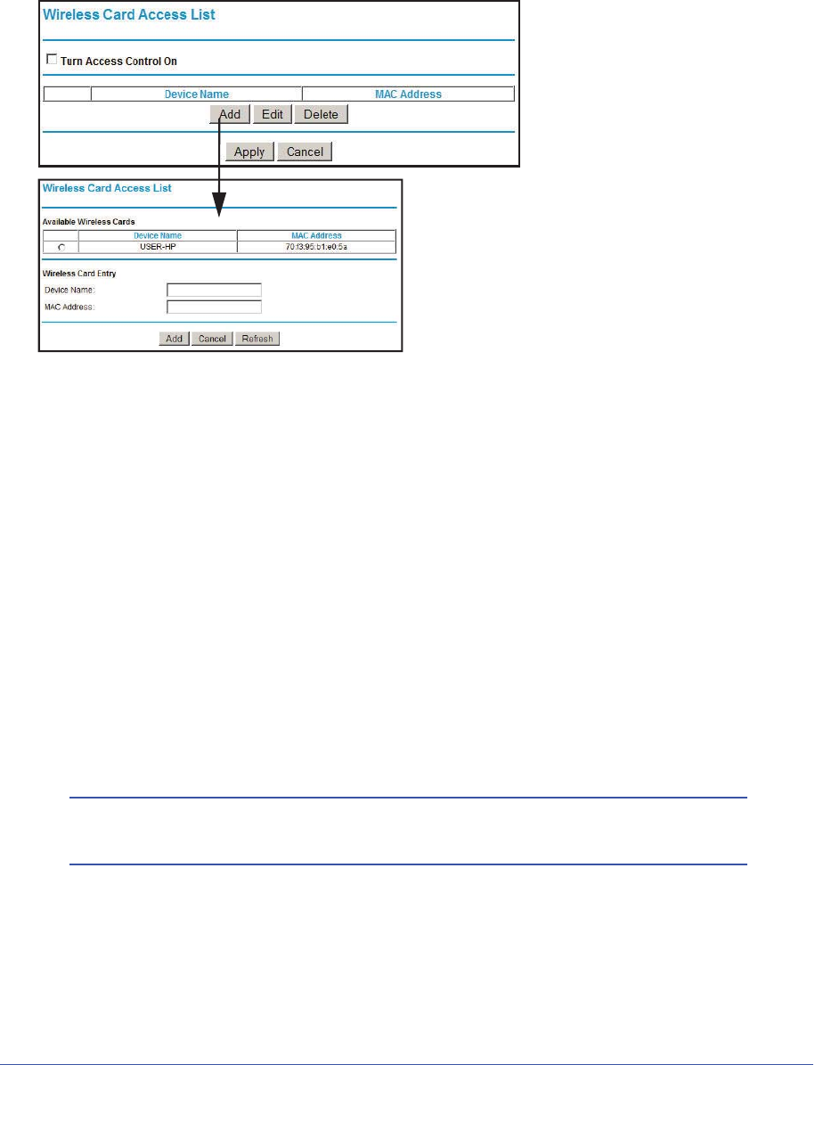
130 | Chapter 8. Advanced Settings
N600 Wireless Dual Band Gigabit ADSL2+ Modem Router DGND3700 User Manual
the Wireless Settings screen, select Setup Access List to display the Wireless Access List
screen.
Building Wireless Bridging and Repeating Networks
With the DGND3700 wireless modem router, you can build large bridged wireless networks
that form an IEEE 802.11n Wireless Distribution System (WDS). Using the modem router
with other access points (APs) and wireless devices, you can connect clients by using their
MAC addresses rather than by specifying IP addresses.
Here are some examples of wireless bridged configurations:
•Point-to-point bridge. The wireless modem router communicates with another
bridge-mode wireless station. See Point-to-Point Bridge Configuration on page 131.
•Multi-point bridge. The wireless modem router is the “master” for a group of bridge-mode
wireless stations. Then all traffic is sent to this master, rather than to other access points.
See Multi-Point Bridge on page 132.
•Repeater with wireless client association. Sends all traffic to the remote access point.
See Repeater with Wireless Client Association on page 134.
Note: The wireless bridging and repeating feature uses the default
security profile to send and receive traffic.
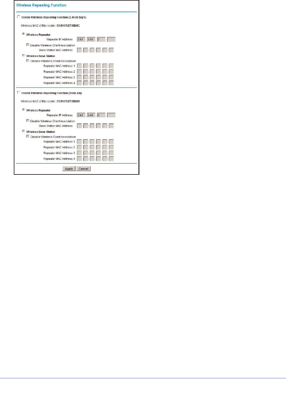
Chapter 8. Advanced Settings | 131
N600 Wireless Dual Band Gigabit ADSL2+ Modem Router DGND3700 User Manual
To view or change these configurations, select Wireless Repeating Function from the main
menu:
Enable Wireless Repeating. Enable this if you wish to use either Bridge mode or Repeater
mode, and then select the mode you want for your environment.
Wireless Repeater. In this mode, the router will communicate only with another Base
Station-mode wireless station. You must enter the MAC address (physical address) of the
other Base Station-mode wireless station in the field provided. WEP can (and should) be
used to protect this communication.
Wireless Base Station. Select this only if this router is the master for a group of
Repeater-mode wireless stations. The other Repeater-mode wireless stations must be set to
Wireless Repeater mode, using this router's MAC address. They then send all traffic to this
master, rather than communicate directly with each other. WEP can (and should) be used to
protect this traffic.
If this option is selected, you must enter the MAC addresses of the other access points in the
fields provided.
Point-to-Point Bridge Configuration
In point-to-point bridge mode, the wireless modem router communicates as an access point
with another bridge-mode wireless station. As a bridge, wireless client associations are
disabled—only wired clients can be connected. You must enter the MAC address of the other
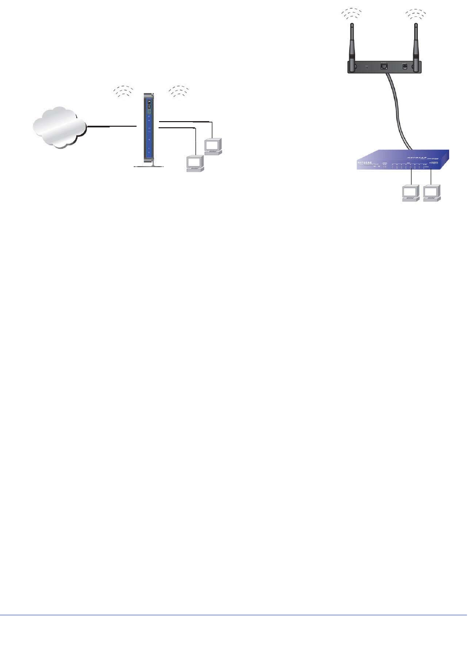
132 | Chapter 8. Advanced Settings
N600 Wireless Dual Band Gigabit ADSL2+ Modem Router DGND3700 User Manual
bridge-mode wireless station in the field provided. Use wireless security to protect this
communication. The following figure shows an example of point-to-point bridge mode.s
LAN Segment 1
PC’s
PC’s
LAN Segment 2
Switch or hub
AP 2
Both access points (APs) are in
Internet
AP 1 (DGND3700 modem router)
point-to-point bridge mode.
192.168.0.1
Figure 52. Point-to-Point Bridge Mode
To set up a point-to-point bridge configuration:
1. Configure the DGND3700 wireless modem router (AP 1) on LAN Segment 1 in
point-to-point bridge mode.
2. Configure the other access point (AP 2) on LAN Segment 2 in point-to-point bridge mode.
The DGND3700 wireless modem router must have AP 2’s MAC address in its Remote
MAC Address field, and AP 2 must have the DGND3700’s MAC address in its Remote
MAC Address field.
3. Configure both APs and verify that both APs are using the same SSID, channel,
authentication mode, if any, and security settings if security is in use.
4. Disable the DHCP server on AP 2. AP 1 will then be the DHCP server.
5. Verify connectivity across LAN Segment 1 and LAN Segment 2. A computer on either LAN
segment should be able to connect to the Internet or share files and printers of any other
PCs or servers connected to LAN Segment 1 or LAN Segment 2.
Multi-Point Bridge
Multi-point bridge mode allows a router to bridge to multiple peer access points
simultaneously. Wireless client associations are disabled. Only wired clients can be
connected. Multi-point bridge mode configuration includes the following steps:
•Enter the MAC addresses of the other access points in the fields provided.
•Set the other bridge-mode access points to point-to-point bridge mode, using the MAC
address of this DGND3700 as the remote MAC address.
•Use wireless security to protect this traffic.
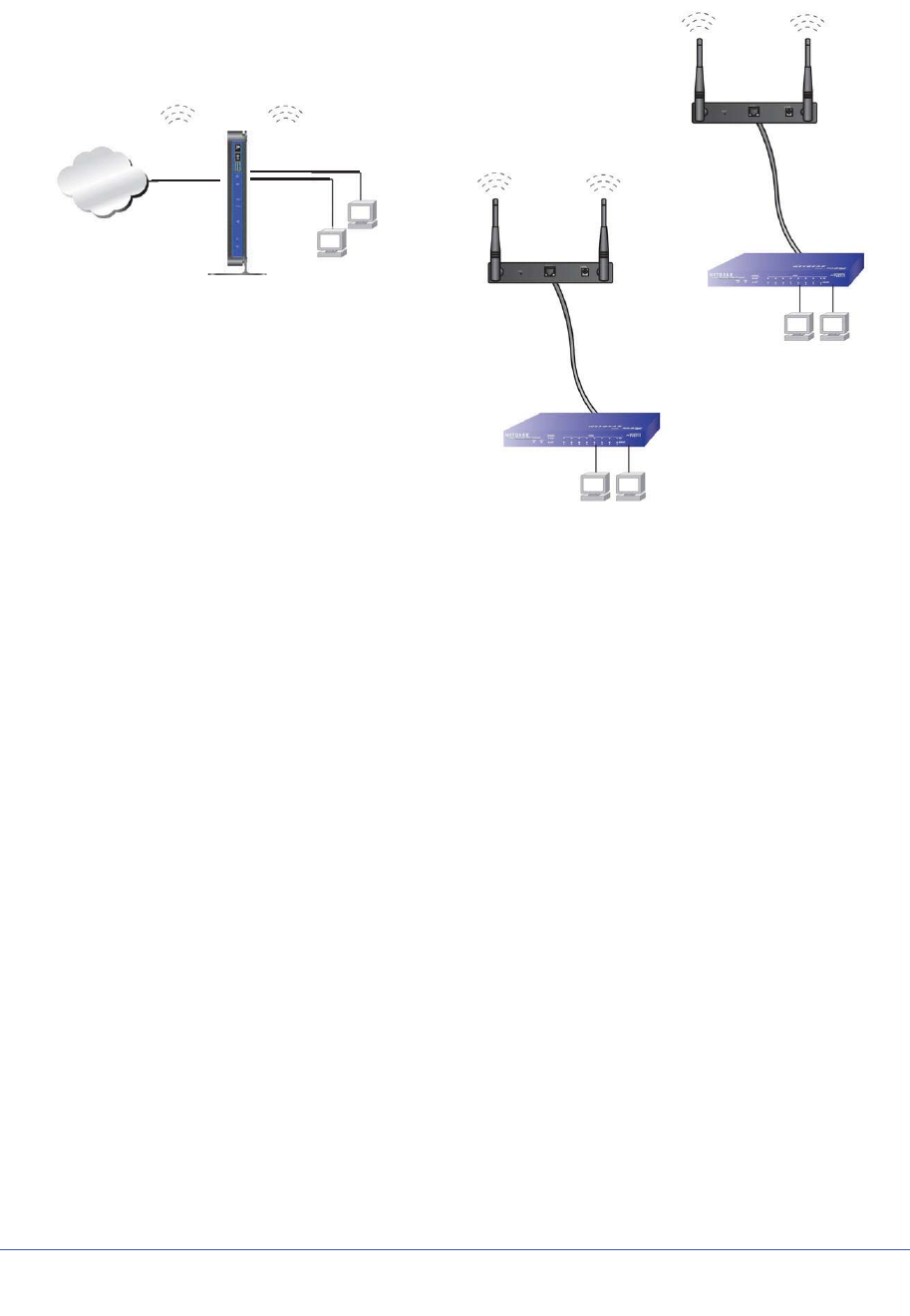
Internet
LAN Segment 1
PCs
PCs
Hub or switch
AP 3
AP 2
Point-to-point
bridge mode
bridge mode
Point-to-point
AP 1
DGND3700
PCs Hub or switch
LAN Segment 3
LAN Segment 2
192.168.0.1
Chapter 8. Advanced Settings | 133
N600 Wireless Dual Band Gigabit ADSL2+ Modem Router DGND3700 User Manual
Figure 53. Multi-Point Bridge Mode
To set up the multi-point bridge configuration:
1. Configure the operating mode of the wireless modem routers.
•Because it is in a central location, configure the DGND3700 wireless modem router
(AP 1) on LAN segment 1 in point-to-multi-point bridge mode, and enter the MAC
addresses of AP 2 and AP 3 in the Remote MAC Address 1 and Remote MAC
Address 2 fields.
•Configure the access point (AP 2) on LAN segment 2 in point-to-point bridge mode
with the remote MAC address of the DGND3700 wireless modem router.
•Configure the access point (AP 3) on LAN segment 3 in point-to-point bridge mode
with the remote MAC address of the DGND3700 wireless modem router.
2. Disable the DHCP server on AP 2 and AP 3. AP 1 will then be the DHCP server.
3. Verify the following for all access points:
•The LAN network configuration of the wireless modem router and other access points
are configured to operate in the same LAN network address range as the LAN
devices.
•Only one access point, the DGND3700 wireless modem router in Figure 53,
Multi-Point Bridge Mode, is configured in point-to-multi-point bridge mode; all the
others are in point-to-point bridge mode.
•All APs, including the DGND3700 wireless modem router, must be on the same LAN.
That is, all the access point LAN IP addresses must be in the same network.

134 | Chapter 8. Advanced Settings
N600 Wireless Dual Band Gigabit ADSL2+ Modem Router DGND3700 User Manual
•If you are using DHCP, all access points should be set to Obtain an IP address
automatically (DHCP Client) in the IP Address Source section of the Basic IP
Settings screen.
•All APs, including the DGND3700 wireless modem router, must use the same SSID,
channel, authentication mode, if any, and WEP security settings if security is in use.
•All point-to-point APs must have the MAC address of AP 1 (the DGND3700 wireless
modem router in the previous figure) in the Remote AP MAC address field.
4. Verify connectivity across the LANs. A computer on any LAN segment should be able to
connect to the Internet or share files and printers with any other PCs or servers connected to
any of the three LAN segments.
Note: Wireless stations configured as they are in Figure 52 on page 132
will not be able to connect to the wireless modem router or access
points. If you require wireless stations to access any LAN segment,
you can use additional access points configured in wireless access
point mode in any LAN segment.
Repeater with Wireless Client Association
In the repeater mode with wireless client association, the DGND3700 wireless modem router
sends all traffic to a remote access point. For the repeater mode, you must enter the MAC
address of the remote “parent” access point. Alternatively, you can configure the DGND3700
wireless modem router as the parent by entering the address of a “child” access point. Note
that the following restrictions apply:
•You do not have the option of disabling client associations with this DGND3700 wireless
modem router.
•You cannot configure a sequence of parent-child APs. You are limited to only one parent
access point, although if the DGND3700 wireless modem router is the parent access
point, it can connect with up to four child APs.
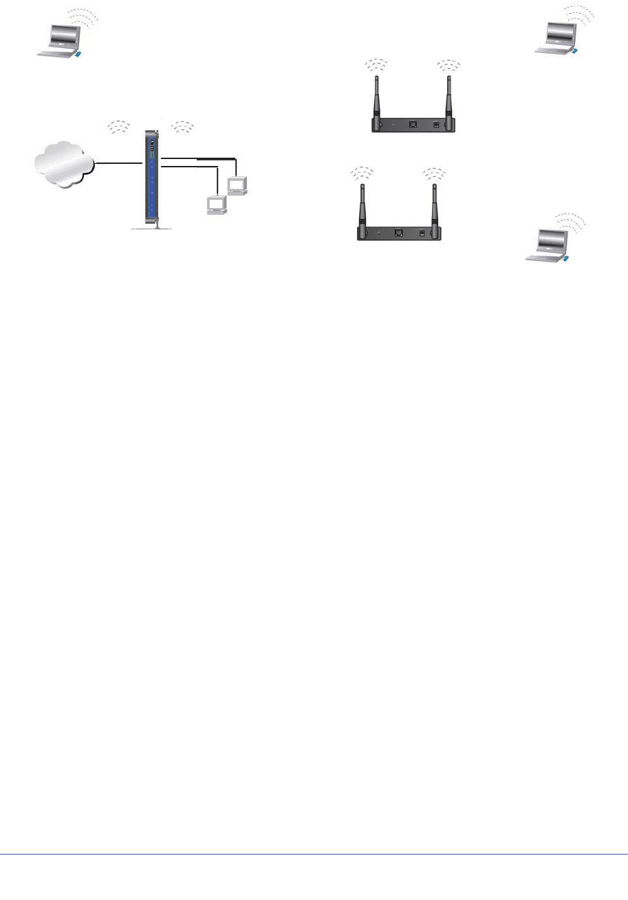
Chapter 8. Advanced Settings | 135
N600 Wireless Dual Band Gigabit ADSL2+ Modem Router DGND3700 User Manual
The following figure shows an example of a repeater mode configuration.
Internet
PCs
Wireless PC
AP 1 (parent AP in repeater mode)
AP 3 in repeater mode
Wireless PC
associated
with AP 3
AP 2 in repeater mode
associated
with AP 2
Wireless PC
with AP 1
associated
DGND3700
192.168.0.1
Figure 54. Repeater Mode
To set up a repeater with wireless client association:
1. Configure the operating mode of the devices.
•Configure AP 1 (the DGND3700 wireless modem router in Figure 54, Repeater Mode)
with the MAC address of AP 2 and AP 3 in the first two Remote MAC Address fields.
•Configure AP 2 with the MAC address of AP 1 in the Remote MAC Address field.
•Configure AP 3 with the MAC address of AP 1 in the Remote MAC Address field.
2. Verify the following for both access points:
•The LAN network configuration of each access point is configured to operate in the
same LAN network address range as the LAN devices.
•The access points must be on the same LAN. That is, the LAN IP addresses for the
access points must be in the same network.
•If you are using DHCP, access point devices should be set to Obtain an IP address
automatically (DHCP Client) in the IP Address Source section of the Basic IP
Settings screen.
•Access point devices must use the same SSID, channel, authentication mode, and
encryption.
3. Verify connectivity across the LANs. A computer on any LAN segment should be able to
connect to the Internet or share files and printers with any other PCs or servers connected
to any of the three WLAN segments.
Remote Management
The Remote Management screen lets you allow a user or users on the Internet to configure,
upgrade, and check the status of your wireless modem router.
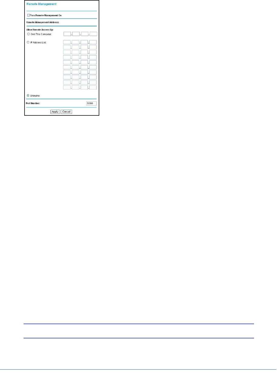
136 | Chapter 8. Advanced Settings
N600 Wireless Dual Band Gigabit ADSL2+ Modem Router DGND3700 User Manual
1. Select Advanced > Remote Management to display this screen:
Figure 55. Remote Management screen
2. Select the Turn Remote Management On check box.
3. Specify the external addresses of wireless modem routers than can access remote
management. For security, restrict access to as few external IP addresses as practical:
•To allow access from a single IP address on the Internet, select Only This Computer
and enter the IP address that is allowed access.
•To allow access from a range of IP addresses on the Internet, select IP Address and
enter a beginning and ending IP address to define the allowed range.
•To allow access from any IP address on the Internet, select Everyone.
4. Specify the port number to be used for accessing the router interface.
Web browser access usually uses the standard HTTP service port 80. For greater
security, you can change it so the remote router interface uses a custom port by entering
that number in the field provided. Choose a number between 1024 and 65535, but do not
use the number of any common service port. The default is 8080, which is a common
alternate for HTTP.
5. Click Apply to save your changes.
To access your wireless modem router from the Internet, type your wireless modem
router’s WAN IP address in your browser’s Address field, followed by a colon (:) and the
custom port number. For example, if your external address is 134.177.0.123 at port
number 8080, enter the following in your browser:
http://134.177.0.123:8080
Note: The http:// must be included in the address.

Chapter 8. Advanced Settings | 137
N600 Wireless Dual Band Gigabit ADSL2+ Modem Router DGND3700 User Manual
Static Routes
Static routes provide additional routing information to your router. Under normal
circumstances, the router has adequate routing information after it has been configured for
Internet access, and you do not need to configure additional static routes. You must configure
static routes only for unusual cases such as multiple routers or multiple IP subnets located on
your network.
Static Route Example
As an example of when a static route is needed, consider the following case:
•Your primary Internet access is through a cable modem to an ISP.
•You have an ISDN router on your home network for connecting to the company where
you are employed. This router’s address on your LAN is 192.168.0.100.
•Your company’s network address is 134.177.0.0.
When you first configured your router, two implicit static routes were created. A default route
was created with your ISP as the wireless modem router, and a second static route was
created to your local network for all 192.168.0.x addresses. With this configuration, if you
attempt to access a device on the 134.177.0.0 network, your router forwards your request to
the ISP. The ISP forwards your request to the company where you are employed, and the
request is likely to be denied by the company’s firewall.
In this case you must define a static route, telling your router that 134.177.0.0 should be
accessed through the ISDN router at 192.168.0.100. The static route setup would look like
Figure 57, Adding a static route.
In this example:
•The Destination IP Address and IP Subnet Mask fields specify that this static route
applies to all 134.177.x.x addresses.
•The Gateway IP Address field specifies that all traffic for these addresses are to be
forwarded to the ISDN router at 192.168.0.100.
•The value in the Metric field represents the number of routers between your network and
the destination. This is a direct connection, so it can be set to the minimum value of 2.
•The Private check box is selected only as a precautionary security measure in case RIP
is activated.
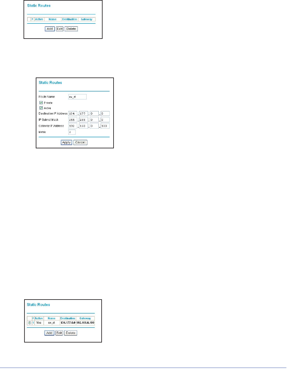
138 | Chapter 8. Advanced Settings
N600 Wireless Dual Band Gigabit ADSL2+ Modem Router DGND3700 User Manual
Configure Static Routes
1. Select Advanced > Static Routes to display the following screen
Figure 56. Static Routes screen
2. To add a static route:
a. Click Add to open the following screen.
Figure 57. Adding a static route
b. In the Route Name field, enter a route name for this static route. This name is for
identification purpose only.
c. Select Private if you want to limit access to the LAN only. The static route will not be
reported in RIP.
d. Select Active to make this route effective.
e. Enter the destination IP address of the final destination.
f. Enter the IP subnet mask for this destination. If the destination is a single host, type
255.255.255.255.
g. Enter the gateway IP address, which has to be a router on the same LAN segment
as the router.
h. In the Metric field, enter a number between 2 and 15 as the metric value. This
represents the number of routers between your network and the destination. Usually,
a setting of 2 or 3 works.
3. Click Apply to save your changes. The Static Routes table is updated to show the new
entry.
Figure 58. Updated static routes
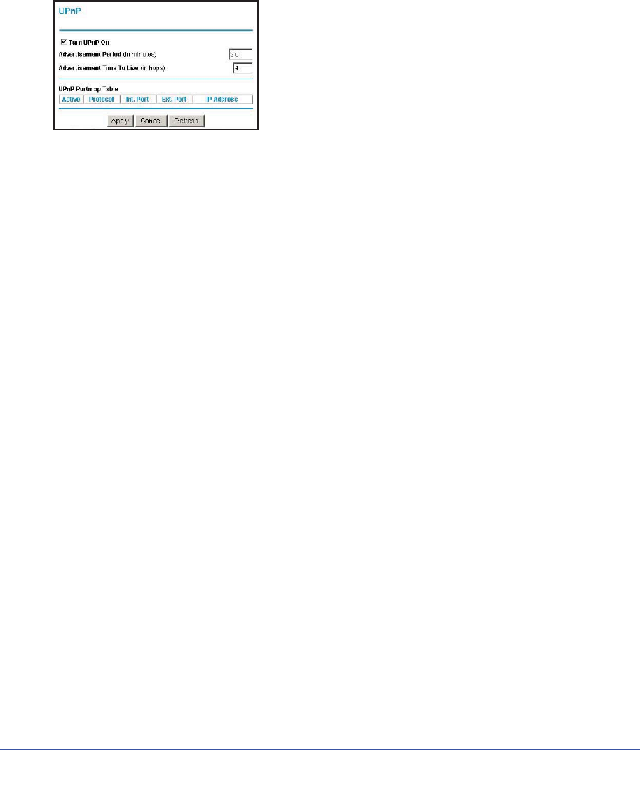
Chapter 8. Advanced Settings | 139
N600 Wireless Dual Band Gigabit ADSL2+ Modem Router DGND3700 User Manual
Universal Plug and Play
Universal Plug and Play (UPnP) helps devices, such as Internet appliances and computers,
access the network and connect to other devices as needed. UPnP devices can
automatically discover the services from other registered UPnP devices on the network.
1. Select Advanced > UPnP to display the following screen:
Figure 59. Universal Plug and Play
2. Fill in the settings as follows:
•Turn UPnP On. UPnP can be enabled or disabled for automatic device configuration.
The default setting for UPnP is enabled. If UPnP is disabled, the wireless modem
router does not allow any device to automatically control the resources, such as port
forwarding (mapping), of the wireless modem router.
•Advertisement Period. The advertisement period is how often the wireless modem
router advertises (broadcasts) its UPnP information. This value can range from 1 to
1440 minutes. The default period is 30 minutes. Shorter durations ensure that control
points have current device status at the expense of additional network traffic. Longer
durations might compromise the freshness of the device status but can significantly
reduce network traffic.
•Advertisement Time To Live. This is measured in hops (steps) for each UPnP
packet sent. A hop is the number of steps allowed to propagate for each UPnP
advertisement before it disappears. The number of hops can range from 1 to 255. The
default value is 4 hops, which works for most home networks. If you notice that some
devices are not being updated or reached correctly, you might need to increase this
value a little.
•UPnP Portmap Table. The UPnP Portmap Table displays the IP address of each
UPnP device that is currently accessing the wireless modem router and which ports
(internal and external) that device has opened. The UPnP Portmap Table also
displays what type of port is opened and if that port is still active for each IP address.
3. To save, cancel your changes, or refresh the table:
•Click Apply to save the new settings to the wireless modem router.
•Click Cancel to disregard any unsaved changes.
•Click Refresh to update the portmap table and to show the active ports that are
currently opened by UPnP devices.
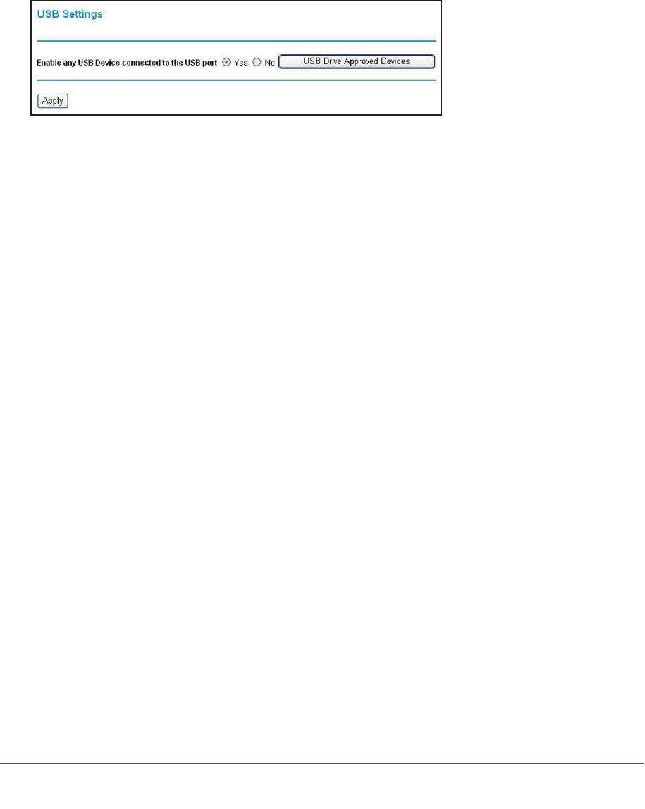
140 | Chapter 8. Advanced Settings
N600 Wireless Dual Band Gigabit ADSL2+ Modem Router DGND3700 User Manual
Advanced USB Settings
For added security the router can be setup to share only approved USB devices. To enable
this feature, select No and click Apply.
To define the approved devices, click Approved Devices.
For more information about USB settings, see USB Storage in Chapter 6.
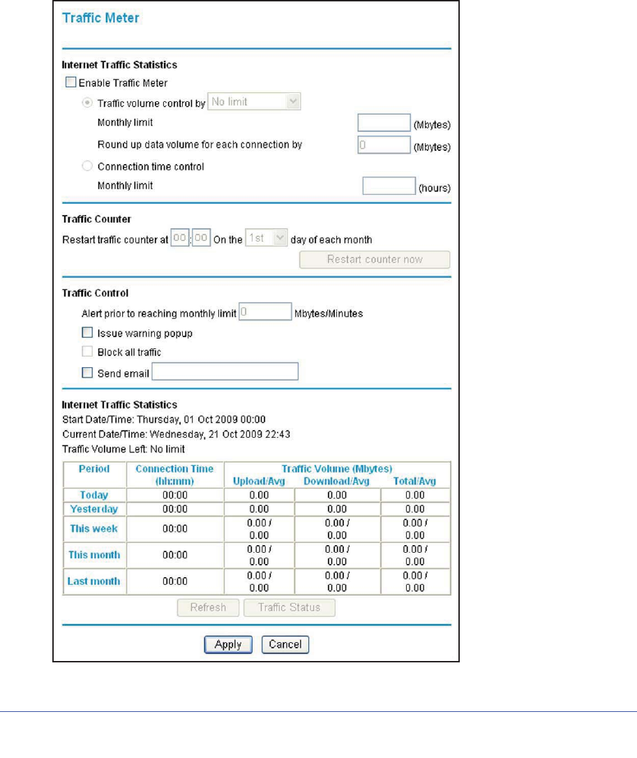
Chapter 8. Advanced Settings | 141
N600 Wireless Dual Band Gigabit ADSL2+ Modem Router DGND3700 User Manual
Traffic Meter
Traffic metering allows you to monitor the volume of Internet traffic passing through your
wireless modem router’s Internet port. With the Traffic Meter utility, you can set limits for
traffic volume, set a monthly limit, and get a live update of traffic usage.
To monitor traffic on your router:
1. Under Advanced on the main menu, select Traffic Meter.

142 | Chapter 8. Advanced Settings
N600 Wireless Dual Band Gigabit ADSL2+ Modem Router DGND3700 User Manual
2. To enable the Traffic Meter, select the Enable Traffic Meter check box.
3. If you would like to record and restrict the volume of Internet traffic, select the Traffic
volume control by radio button. You can select one of the following options for controlling
the traffic volume:
•No Limit. No restriction is applied when the traffic limit is reached.
•Download only. The restriction is applied to incoming traffic only.
•Both Directions. The restriction is applied to both incoming and outgoing traffic.
4. You can limit the amount of data traffic allowed per month:
•By specifying how many Mbytes per month are allowed.
•By specifying how many hours of traffic are allowed.
5. Set the Traffic Counter to begin at a specific time and date.
6. Set up Traffic Control to issue a warning message before the monthly limit of Mbytes or
hours is reached. You can select one of the following to occur when the limit is attained:
•The Internet LED flashes green or amber.
•The Internet connection is disconnected and disabled.
7. Set up Internet Traffic Statistics to monitor the data traffic.
8. Click the Traffic Status button if you want a live update on Internet traffic status on your
router.
9. Click Apply to save your settings.