Netgear orporated ME103 802.11b Access Point User Manual users manual
Netgear Incorporated 802.11b Access Point users manual
Contents
- 1. users manual
- 2. Users Manual
users manual

802.11b
Wireless Access Point
User's Guide

i
TABLE OF CONTENTS
CHAPTER 1 INTRODUCTION .............................................................................................1
Wireless LANs ...................................................................................................................1
Features of your Wireless Access Point...........................................................................3
Package Contents ..............................................................................................................4
Physical Details..................................................................................................................5
CHAPTER 2 INSTALLATION...............................................................................................7
Requirements.....................................................................................................................7
Procedure...........................................................................................................................7
CHAPTER 3 ACCESS POINT SETUP..................................................................................9
Overview ............................................................................................................................9
Preparation ........................................................................................................................9
Connecting to the Wireless Access Point.........................................................................9
IP Settings Screen............................................................................................................11
Wireless Screen................................................................................................................13
Wireless Mode .................................................................................................................14
Security Settings..............................................................................................................14
Change Password Screen................................................................................................17
CHAPTER 4 PC AND SERVER CONFIGURATION .......................................................19
Wireless Station Configuration......................................................................................19
Radius Server Configuration .........................................................................................20
CHAPTER 5 OPERATION AND STATUS.........................................................................21
Operation .........................................................................................................................21
Information Screen .........................................................................................................21
Activity Log......................................................................................................................23
Station List.......................................................................................................................24
Statistics Screen...............................................................................................................25
CHAPTER 6 OTHER SETTINGS & FEATURES .............................................................27
Overview ..........................................................................................................................27
Upgrade Firmware..........................................................................................................27
Backup/Restore Settings.................................................................................................28
Reset Access Point...........................................................................................................29
Access Control .................................................................................................................30
APPENDIX A SPECIFICATIONS .......................................................................................33
Wireless Access Point......................................................................................................33
APPENDIX B TROUBLESHOOTING ................................................................................36
Overview ..........................................................................................................................36
General Problems............................................................................................................36
Internet Access.................................................................................................................36
APPENDIX C WINDOWS TCP/IP.......................................................................................38
Overview ..........................................................................................................................38
Checking TCP/IP Settings - Windows 9x/ME:.............................................................38
Checking TCP/IP Settings - Windows NT4.0 ...............................................................40
ii
P/N:
Copyright 2003. All Rights Reserved.
Document Version: 1.0
All trademarks and trade names are the properties of their respective owners.
Chapter 1
Introduction
This Chapter provides an overview of the Wireless Access Point's features
and capabilities.
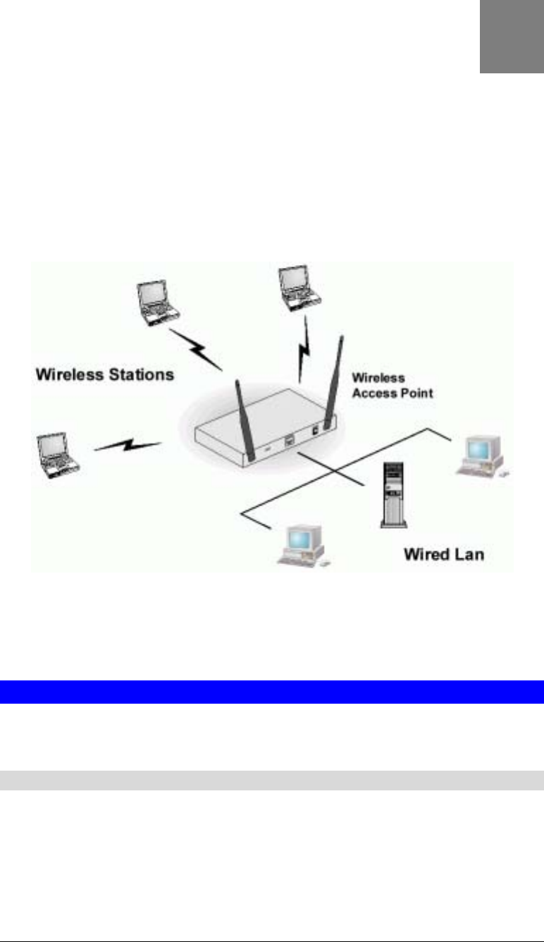
Congratulations on the purchase of your new Wireless Access Point. The Wireless Access
Point links your 802.11b wireless stations to your wired LAN. The Wireless stations and
devices on the wired LAN are then on the same network, and can communicate with each
other without regard for whether they are connected to the network via a Wireless or wired
connection.
Figure 1: Wireless Access Point
The auto-sensing capability of the Wireless Access Point allows packet transmission up to
11Mbps for maximum throughput, or automatic speed reduction to lower speeds when the
environment does not permit maximum throughput.
Wireless LANs
Wireless networks have their own terms and jargon. It is necessary to understand many of
these terms in order to configure and operate a Wireless LAN.
Modes
Wireless LANs can work in either of two (2) modes:
• Ad-hoc
• Infrastructure
1

Wireless Access Point User Guide
2
Ad-hoc Mode
Ad-hoc mode does not require an Access Point or a wired (Ethernet) LAN. Wireless
Stations (e.g. notebook PCs with wireless cards) communicate directly with each other.
Infrastructure Mode
In Infrastructure Mode, one or more Access Points are used to connect Wireless Stations
(e.g. Notebook PCs with wireless cards) to a wired (Ethernet) LAN. The Wireless Stations
can then access all LAN resources.
Access Points can only function in "Infrastructure" mode,
and can communicate only with Wireless Stations which are
set to "Infrastructure" mode.
SSID/ESSID
BSS/SSID
A group of Wireless Stations and a single Access Point, all using the same ID (SSID),
form a Basic Service Set (BSS).
Using the same SSID is essential. Devices with different SSIDs are unable to
communicate with each other. However, some Access Points allow connections from
Wireless Stations which have their SSID set to “any” or whose SSID is blank ( null ).
ESS/ESSID
A group of Wireless Stations, and multiple Access Points, all using the same ID (ESSID),
form an Extended Service Set (ESS).
Different Access Points within an ESS can use different Channels. To reduce interference,
it is recommended that adjacent Access Points SHOULD use different channels.
As Wireless Stations are physically moved through the area covered by an ESS, they will
automatically change to the Access Point which has the least interference or best
performance. This capability is called Roaming. (Access Points do not have or require
Roaming capabilities.)
Channels
The Wireless Channel sets the radio frequency used for communication.
• Access Points use a fixed Channel. You can select the Channel used. This allows you to
choose a Channel which provides the least interference and best performance. In the USA
and Canada, 11 channels are available.
• If using multiple Access Points, it is better if adjacent Access Points use different
Channels to reduce interference. The recommended Channel spacing between adjacent
Access Points is 5 Channels (e.g. use Channels 1 and 6, or 6 and 11).
• In "Infrastructure" mode, Wireless Stations normally scan all Channels, looking for an
Access Point. If more than one Access Point can be used, the one with the strongest signal
is used. (This can only happen within an ESS.)
• If using "Ad-hoc" mode (no Access Point), all Wireless stations should be set to use the
same Channel. However, most Wireless stations will still scan all Channels to see if there
is an existing "Ad-hoc" group they can join.

Introduction
3
WEP
WEP (Wired Equivalent Privacy) is a standard for encrypting data before it is transmitted.
This is desirable because it is impossible to prevent snoopers from receiving any data which is
transmitted by your Wireless Stations. But if the data is encrypted, then it is meaningless
unless the receiver can decrypt it.
If WEP is used, the Wireless Stations and the Wireless Access Point must have the same
settings.
Configuring your Wireless LAN
To allow Wireless Stations to use the Access Point, the Wireless Stations and the Access Point
must use the same settings, as follows:
Mode On client Wireless Stations, the mode must be set to "Infrastructure".
(The Access Point is always in "Infrastructure" mode.)
Channel The Access Point should be set to the Channel you wish to use.
• If using multiple Access Points, they should use different Channels
to reduce interference. The recommended channel separation
between adjacent Access Points is 5 channels (e.g. Use channels 1,
6, and 11)
• It is not necessary to set the Channel on Wireless stations; they will
scan all Channels to locate the Channel used by the Access Point.
SSID (ESSID) Wireless Stations should use the same SSID (ESSID) as the Access
Point they wish to connect to.
Alternatively, the SSID on Wireless Stations (but not the Access Point)
can be set to "any" or null (blank) to allow connection to any Access
Point, if the Access Points support this feature.
WEP The Wireless Stations and the Access Point must use the same settings
for WEP (Off, 64 Bit, or 128 Bit).
WEP Key: If WEP is enabled, the Key Table (for 64 Bit encryption) or
Key (for 128 Bit Encryption) must be the same on the Wireless Stations
and the Access Point.
WEP Authentication: The Wireless Access Point supports both
methods ("Open System" or "Shared Key") simultaneously, so normally
it does not matter system the Wireless stations use. But if you change the
Wireless Access Point to use one method only, then all Wireless stations
must use the same settings.
User Name,
Password
If using 802.1x mode, each Wireless station must have a user name and
password on the Radius Server used for authentication.
Features of your Wireless Access Point
The Wireless Access Point incorporates many advanced features, carefully designed to provide
sophisticated functions while being easy to use.

Wireless Access Point User Guide
4
• Standards Compliant. The Wireless Access Point complies with the IEEE 802.11b
(DSSS) and IEEE 802.1x specifications for Wireless LANs.
• 802.1x Support. Support for 802.1x mode is included, providing for the industrial-
strength wireless security of 802.1x authentication and authorization.
• Radius Client Support. The Wireless Access Point can login to your existing Radius
Server (as a Radius client).
• Dynamic WEP key Support. In 802.1x mode, either fixed or Dynamic WEP keys can be
used.
• Upgradeable Firmware. Firmware is stored in a flash memory and can be upgraded
easily, using only your Web Browser.
• WEP support. Support for WEP (Wired Equivalent Privacy) is included. Both 64 Bit
and 128 Bit keys are supported.
• Access Control. The Access Control feature can ensure that only trusted Wireless
Stations can use the Wireless Access Point to gain access to your LAN.
• Simple Configuration. If the default settings are unsuitable, they can be changed
quickly and easily.
• DHCP Client Support. Dynamic Host Configuration Protocol provides a dynamic IP
address to PCs and other devices upon request. The Wireless Access Point can act as a
DHCP Client, and obtain an IP address and related information from your existing DHPC
Server.
• NetBIOS & WINS Support. Support for both NetBIOS broadcast and WINS
(Windows Internet Naming Service) allows the Wireless Access Point to easily fit into
your existing Windows network.
• Password - protected Configuration. Optional password protection is provided to
prevent unauthorized users from modifying the configuration data and settings.
Package Contents
The following items should be included:
• Wireless Access Point
• Power Adapter
• 2 Wireless Antennae
• Quick Start Guide
• Documentation CD-ROM
• Extended Warranty/Registration Card
If any of the above items are damaged or missing, please contact your dealer immediately.

Introduction
5
Physical Details
Front Panel LEDs
Figure 2: Front Panel
Status On - Error condition.
Off - Normal operation.
Blinking - This LED blinks during start up, or when the Firmware is being
upgraded.
Power On - Normal operation.
Off - No power
Link/Act On - The LAN (Ethernet) port is active.
Off - No active connection on the LAN (Ethernet) port.
Flashing - Data is being transmitted or received via the corresponding
LAN (Ethernet) port.
100 On - LAN (Ethernet) port is using 100BaseT.
Off - LAN (Ethernet) port connection is using 10BaseT, or is not active.
WLAN On - Wireless connection is available; Wireless Access Point is ready for
use.
Off - No Wireless connection available.
Flashing - Data is being transmitted or received via the Wireless access
point. Data includes "network traffic" as well as user data.

Wireless Access Point User Guide
6
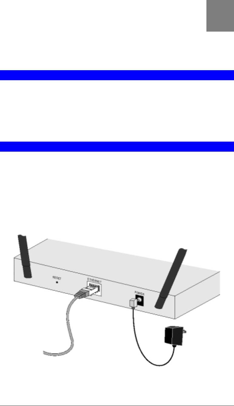
Rear Panel
Figure 3 Rear Panel
Antennae Two antennae (aerials) are supplied. These must be fitted to the
mounting points on either end on the rear panel.
Best results are usually obtained with the antennae in a vertical
position.
Reset Button This button has two (2) functions:
• Reboot. When pressed and released, the Wireless Access Point
will reboot (restart).
• Reset to Factory Defaults. This button can also be used to clear
ALL data and restore ALL settings to the factory default values.
To Clear All Data and restore the factory default values:
1. Power Off the router
2. Hold the Reset Button down while you Power On the router.
3. Continue holding the Reset Button until the Status (Red) LED
blinks TWICE.
4. Release the Reset Button.
The factory default configuration has now been restored, and the
Router is ready for use.
Ethernet Use a standard LAN cables (RJ45 connectors) to connect this port to a
10BaseT or 100BaseT hub on your LAN.
Power port Connect the supplied power adapter here.
Chapter 2
Installation
This Chapter covers the physical installation of the Wireless Access Point.
Requirements
Requirements:
• TCP/IP network
• Ethernet cable with RJ-45 connectors
• Installed Wireless network adapter for each PC that will be wirelessly connected to the
network
Procedure
Before commencing, select a suitable location for the installation of your Wireless Access
Point. To maximize reliability and performance, follow these guidelines:
• Use an elevated location, such as wall mounted or on the top of a cubicle.
• Place the Wireless Access Point near the center of your wireless coverage area.
• If possible, ensure there are no thick walls or metal shielding between the Wireless Access
Point and Wireless stations. Under ideal conditions, the Wireless Access Point has a range
of around 100 meters (300 feet). The range is reduced, and transmission speed is lower, if
there are any obstructions between Wireless devices.
Figure 4: Installation Diagram
2

Wireless Access Point User Guide
8
1. Attach the wireless antennae to the connectors provided on the back of the router. Secure
each antenna by turning the grooved or ridged ring on the antenna until snug (Do not over
tighten).
2. Use a standard LAN cable to connect the “Ethernet” port on the Wireless Access Point to
a 10/100BaseT hub on your LAN.
3. Connect the supplied power adapter to the Wireless Access Point and a convenient power
outlet.
4. Check the LEDs:
• The Status LED should flash, then turn OFF.
• The Power, WLAN, and Link/Act (LAN) LEDs should be ON.
For more information, refer to Front Panel LEDs in Chapter 1.

Chapter 3
Access Point Setup
This Chapter provides details of the Setup process for Basic Operation of
your Wireless Access Point.
Overview
This chapter describes the setup procedure to make the Wireless Access Point a valid device
on your LAN, and to function as an Access Point for your Wireless Stations.
Wireless Stations may also require configuration. For details, see Chapter 4 - Wireless Station
Configuration.
The Wireless Access Point can be configured using your Web Browser. Your Browser must
support JavaScript. The configuration program has been tested on the following browsers:
• Netscape V4.08 or later
• Internet Explorer V4 or later
Preparation
1. Install the Wireless Access Point in your LAN, as described previously.
2. Check the Wireless Access Point to determine its Default Name. This is shown on a label
on the base or rear, and is in the following format:
ME103_xxxxxx
Where xxxxxx is a set of 6 Hex characters ( 0 ~ 9, and A ~ F ).
3. Use a PC which is already connected to your LAN, either by a wired connection or
another Access Point.
• Until the Wireless Access Point is configured, establishing a Wireless connection to it
may be not possible.
• If your LAN contains a Router or Routers, ensure the PC used for configuration is on
the same LAN segment as the Wireless Access Point.
Connecting to the Wireless Access Point
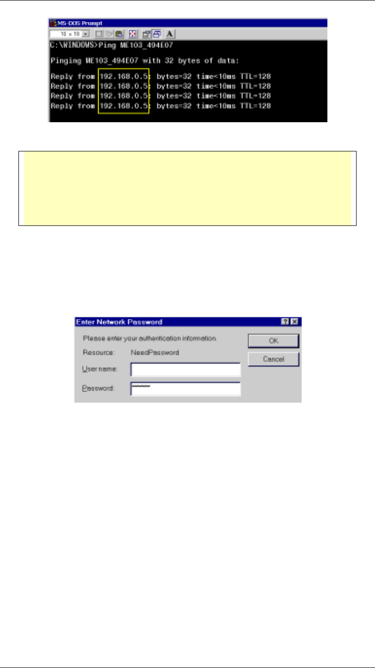
1. Open a MS-DOS Prompt or Command Prompt Window.
2. Use the Ping command to “ping” the Wireless Access Point.
Enter ping followed by the Default Name of the Wireless Access Point.
e.g.
ping ME103_494E07
3. Check the output of the ping command to determine the IP address of the Wireless Access
Point, as shown below.
3
Wireless Access Point User Guide
10
Figure 5: Ping Command
If there is no reply (“Request timed out”)
• Check that the Wireless Access Point is properly installed, LAN connection is
OK, and it is powered ON.
• Ensure that your PC and the Wireless Access Point are on the same network
segment. (If you don't have a router, this must be the case.)
4. Start your Web browser.
5. In the Address box, enter "HTTP://" and the IP Address of the Wireless Access Point
e.g.
HTTP://192.168.0.5
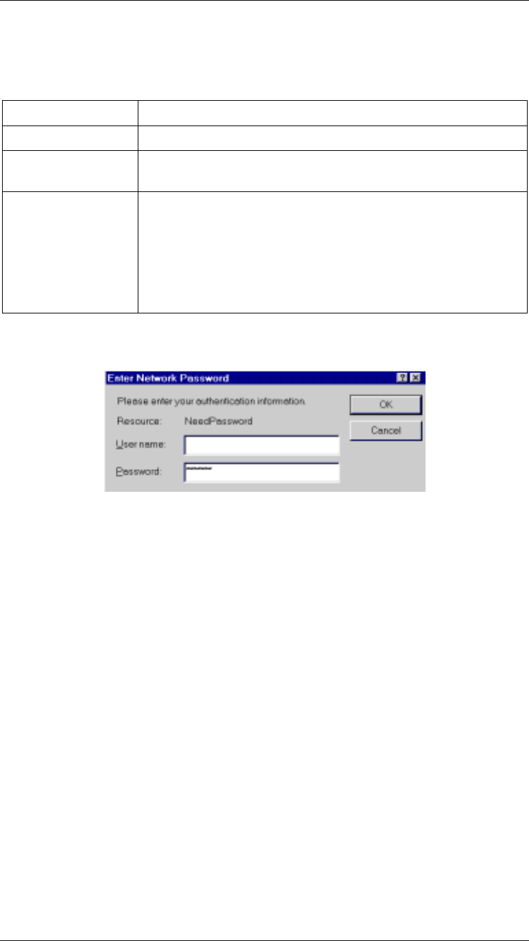
6. You should then see a login prompt, which will ask for a User Name and Password.
Figure 6: Password Dialog
7. Enter admin for the user name, and password for the password.
These are the default values. The password (but not the user name) can and should be
changed. Always enter the current password, as set on the Change Password screen.
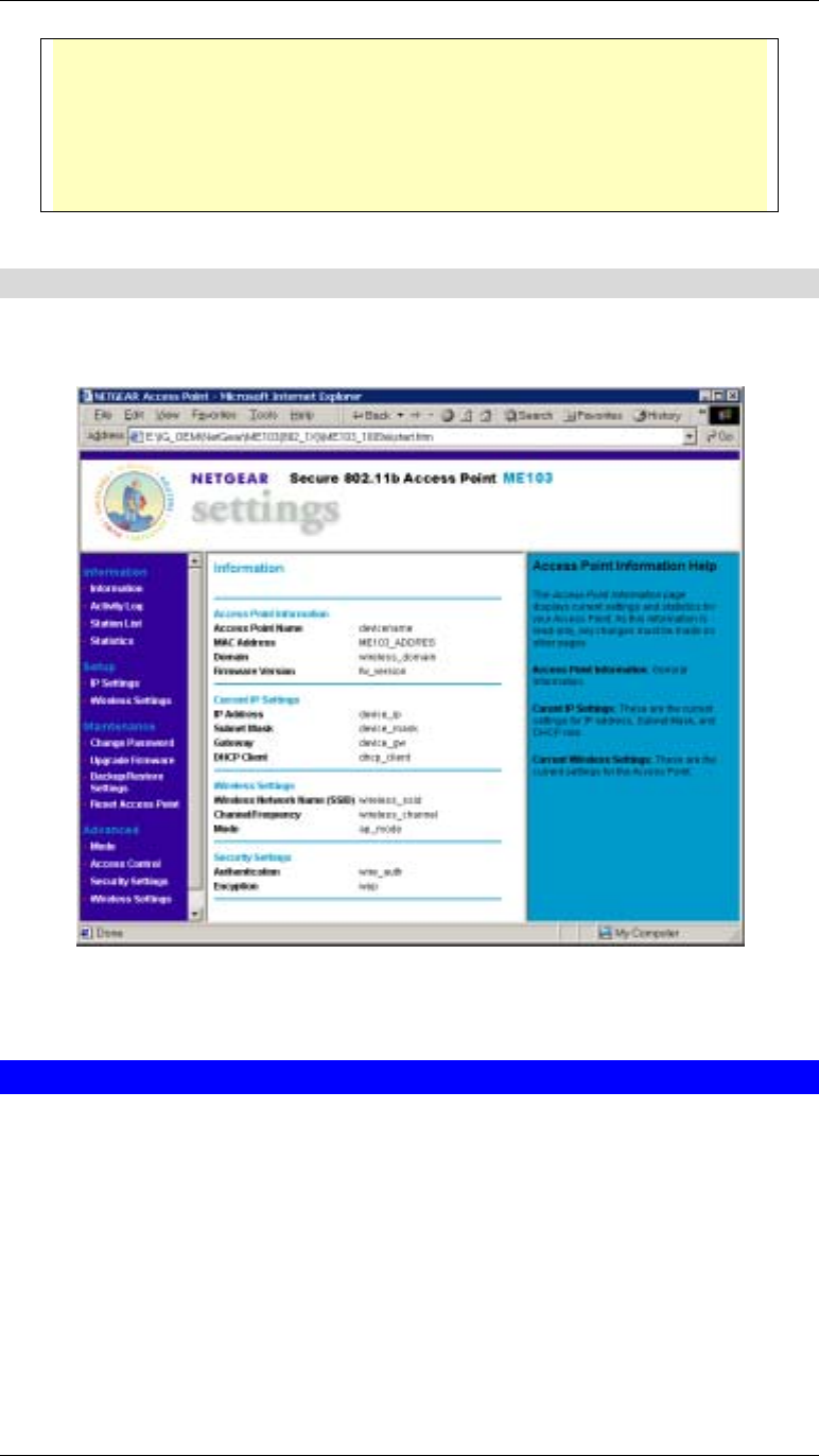
8. You will then see the Information screen, which displays the current settings and status.
No data input is possible on this screen.
9. From the menu, select and configure the following screens, as described in the following
sections:
• IP Settings
• Wireless Settings
• Wireless Mode
• Security Settings
• Change Password
10. Setup of the Wireless Access Point is now complete.
Wireless stations must now be set to match the Wireless Access Point. See Chapter 4 for
details.
Setup
11
If you can't connect:
It is likely that your PC’s IP address is incompatible with Wireless Access Point’s
IP address. This can happen if your LAN does not have a DHCP Server.
It this case, you must change your PC’s IP address to match the Wireless Access
Point. See Appendix C - Windows TCP/IP for details for this procedure.
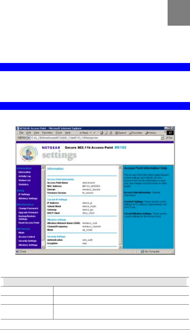
Information Screen
When you first connect, you will see the Information screen. This displays the current settings
and status of the Wireless Access Point. No data can be input on this screen.
Figure 7: Information Screen
For further details of this screen, refer to Information Screen in Chapter 5.
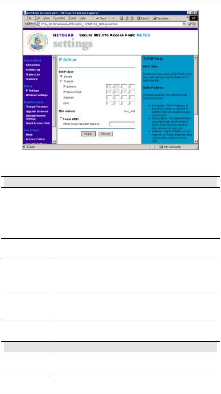
IP Settings Screen
The settings on this screen must be suitable for your existing network.
Click IP Settings on the menu to view a screen like the following.
Wireless Access Point User Guide
12
Figure 8: IP Settings Screen
Data - IP Settings Screen
DHCP Client
Enable/Disable If set to Enable, the Wireless Access Point will obtain an IP address
from your DHCP Server. This is the default.
If set to Disable, you need to enter the IP Address, IP Subnet Mask,
Gateway, and DNS, as explained below.
This setting should be changed to Disable if your LAN does not have a
DHCP Server.
IP Address Only required if DHCP Client is set to Disable.
Enter an unused IP Address from within the range used by your LAN.
IP Subnet Mask Only required if DHCP Client is set to Disable.
Enter the Subnet Mask for the LAN segment to which the Wireless
Access Point is attached (the same value as the PCs on that LAN
segment).
Gateway Only required if DHCP Client is set to Disable.
Enter the Gateway for the LAN segment to which the Wireless Access
Point is attached (the same value as the PCs on that LAN segment).
DNS Only required if DHCP Client is set to Disable.
Enter the DNS (Domain Name Server) used by PCs on your LAN.
MAC Address
MAC Address The MAC address (physical address) of the Wireless Access Point is
displayed here. This is for information only; the MAC address cannot
be changed.
Setup
13
WINS
Enable WINS If your LAN has a WINS server, enable this setting, and enter the
name or IP address of your WINS server.
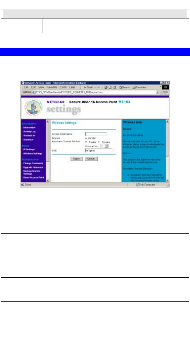
Wireless Screen
The settings on this screen must match the settings used by Wireless Stations.
Click Wireless on the menu to view a screen like the following.
Figure 9: Wireless Screen
Wireless Screen
Access Point Name The default name may be changed if desired.
Note: In 802.1x mode, this name is used as the Client Login Name
for the Radius Server.
Domain This will display the domain or region for which the Wireless
module is licensed for use.
Automatic
Channel Selection If set to Enable, the Wireless Access Point will self-select a Wireless
Channel.
If set to Disable, the Channel you select in the drop-down list will be
used.
SSID This must match the value used on the Wireless Access Point. The
default value is netgear
Note: The SSID is case sensitive.
Wireless Access Point User Guide
14
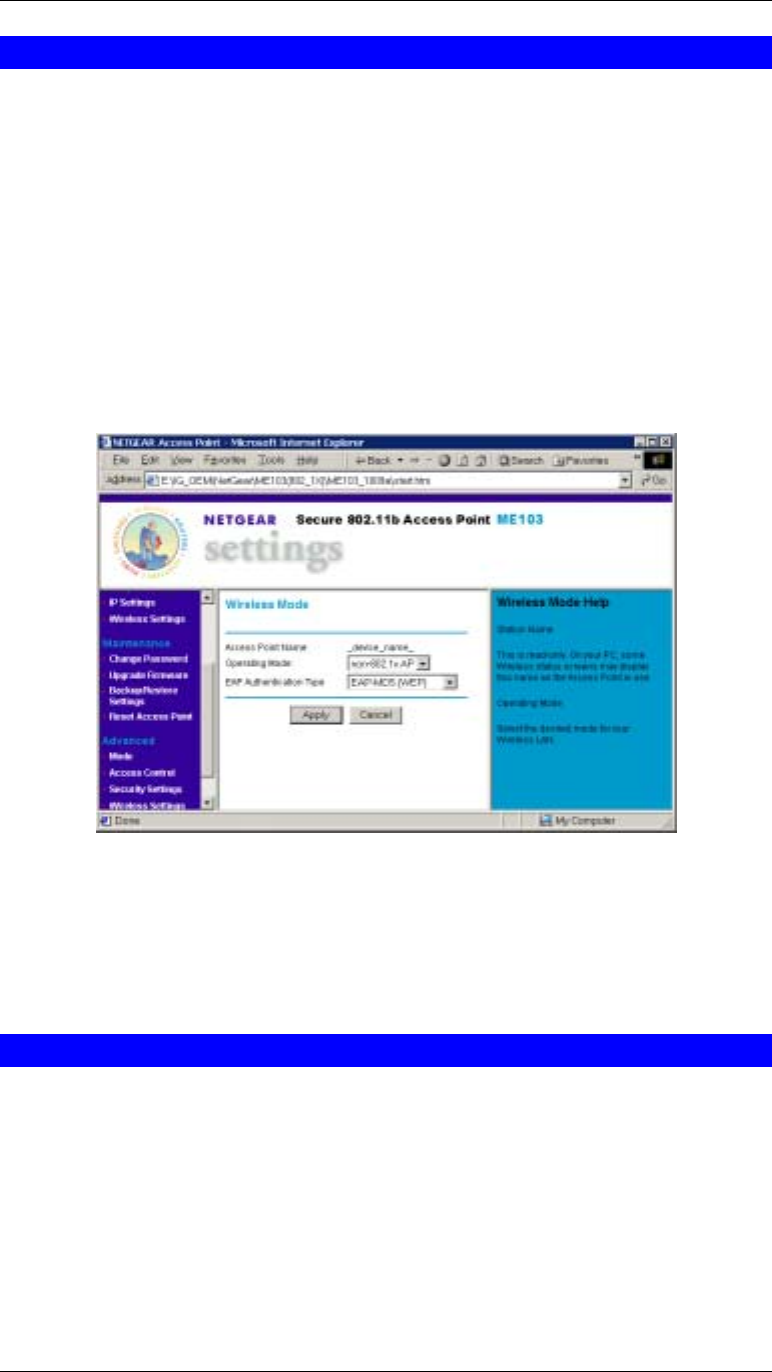
Wireless Mode
The Mode screen allows you to change the default mode of the Wireless Access Point, if
desired.
The following modes are supported.
• 802.1x Access Point - the Wireless Access Point functions according to the IEEE 802.1x
specifications. Select this mode only if :
• All of your Wireless Stations comply with the 802.1x standard. The will require
802.1x software which can pass their User Name and Password to the Radius Server.
• Your LAN contains a Radius Server which can provide authentication services for
Wireless users.
• non 802.1x Access Point - the Wireless Access Point functions according to the IEEE
802.11b standard. This is the default setting, and is the most common standard in use at
this time. No Radius Server is required or used.
Figure 10 Wireless Mode
To view this screen, select Mode from the menu.
Note that changing the Mode on this screen affects the Security screen, as described in the
following section.
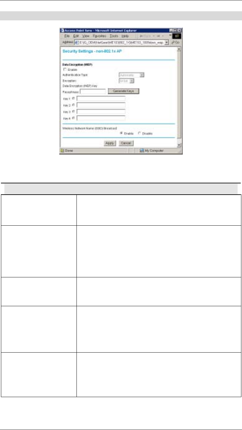
Security Settings
The Security Settings screen will vary according to the Mode of the Wireless Access Point.
In the default Mode (non-802.1x Access Point), clicking the Security Settings link on the menu
will result in a screen like the following.
Setup
15
Security Settings - non 802.1x Mode
Figure 11: Security Settings - non 802.1x Mode
Data - Security Screen (non 802.1x Mode)
Data Encryption
Enable Enable this if you wish to use WEP.
• You must provide at least one Key value.
• All Wireless Stations must have the same settings.
Authentication Type Normally, you can leave this at “Automatic”, so that Wireless
Stations can use either method ("Open System" or "Shared
Key".).
If you wish to use a particular method, select the appropriate
value - "Open System" or "Shared Key". All Wireless stations
must then be set to use the same method.
Encryption Select the desired option:
• 64 Bit Encryption
• 128 Bit Encryption
Passphrase To generate a key or set of keys from a word or phrase:
1. Select the type of key required (64 Bit or 128 Bit)
2. Enter the word or phrase in the "Passphrase" field.
3. Click the "Generate Keys" button.
4. The screen will refresh with the key value(s) inserted.
Key 1.. Key 4 Select the key you wish to be the default. Transmitted data is
ALWAYS encrypted using the Default Key; the other Keys
are for decryption only.
All Wireless stations must use the same key as the Access
Point.
Wireless Access Point User Guide
16
SSID Broadcast
Wireless Network Name
(SSID) Broadcast If set to Enable, the Wireless Access Point will broadcast its
SSID, allowing Wireless Stations which have a “null” (blank)
SSID to adopt the correct SSID. If set to Disable, the SSIS is
not broadcast.
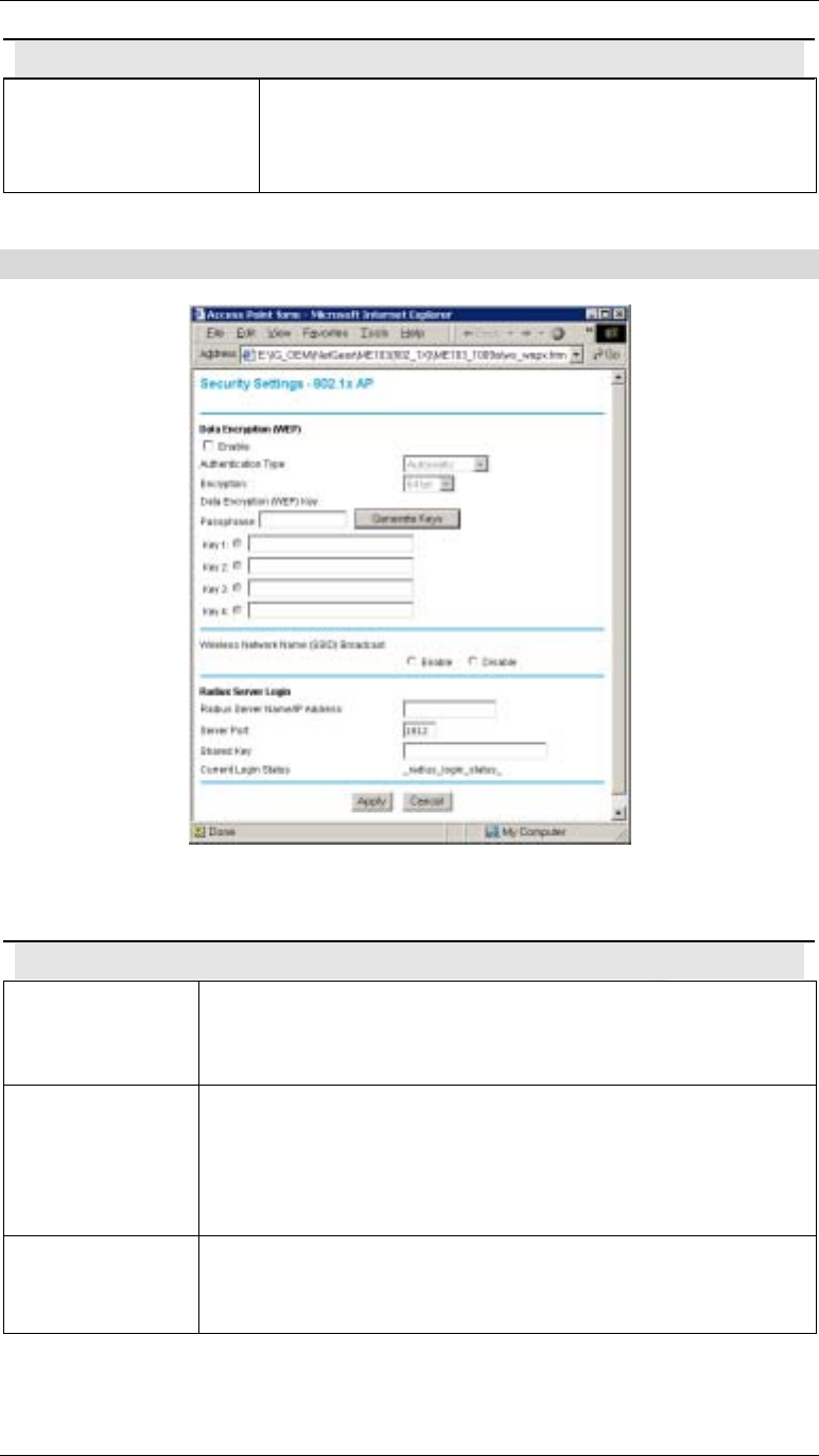
Security Settings - 802.1x Mode
Figure 12: Security Settings - 802.1x Mode
Data - Security Screen (non 802.1x Mode)
Data Encryption
Enable Enable this if you wish to use WEP.
• You must provide at least one Key value.
• All Wireless Stations must have the same settings.
Authentication
Type Normally, you can leave this at “Automatic”, so that Wireless
Stations can use either method ("Open System" or "Shared Key".).
If you wish to use a particular method, select the appropriate value -
"Open System" or "Shared Key". All Wireless stations must then be
set to use the same method.
Encryption Select the desired option:
• 64 Bit Encryption
• 128 Bit Encryption
Setup
17
Passphrase To generate a key or set of keys from a word or phrase:
5. Select the type of key required (64 Bit or 128 Bit)
6. Enter the word or phrase in the "Passphrase" field.
7. Click the "Generate Keys" button.
8. The screen will refresh with the key value(s) inserted.
Key 1.. Key 4 Select the key you wish to be the default. Transmitted data is
ALWAYS encrypted using the Default Key; the other Keys are for
decryption only.
All Wireless stations must use the same key as the Access Point.
SSID Broadcast
Wireless Network
Name (SSID)
Broadcast
If set to Enable, the Wireless Access Point will broadcast its SSID,
allowing Wireless Stations which have a “null” (blank) SSID to
adopt the correct SSID. If set to Disable, the SSIS is not broadcast.
Radius Server Login
Radius Server
Name/IP address Enter the name or IP address of the Radius Server on your network.
Server Port Enter the port number used for connections to the Radius Server.
Shared Key This is used for the Client Login on the Radius Server. Enter the key
value to match the Radius Server.
Note: The Client Name is the name of the Wireless Access Point.
Current Login
Status This read-only field displays the current login status, to the Radius
Server, for this Wireless Access Point.
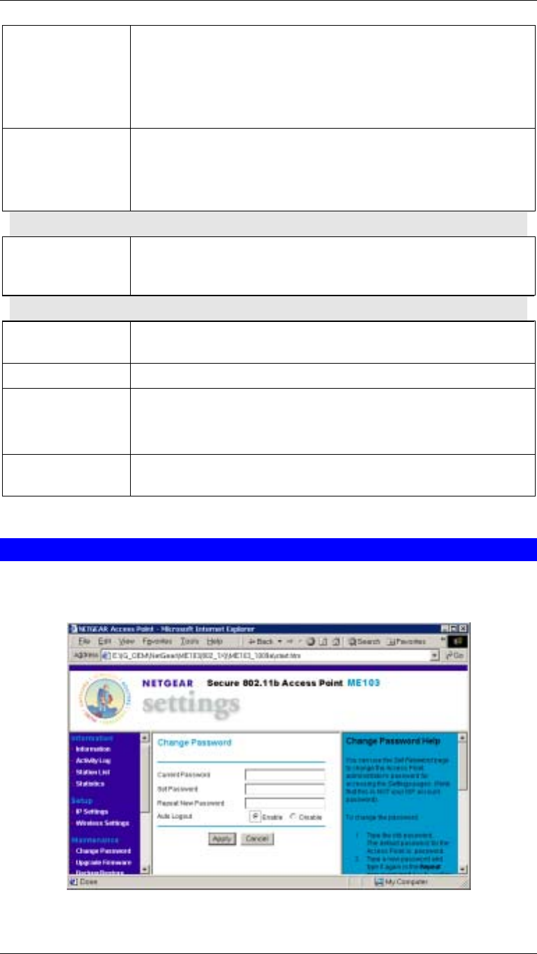
Change Password Screen
The password screen allows you to assign a password to the Wireless Access Point. This
password limits access to the configuration interface.
Figure 13: Change Password Screen
Wireless Access Point User Guide
18
The default password is password
It is recommended that this be changed, using this screen.
Data - Change Password Screen
Current Password Enter the current password here
Set Password Enter the new password here
Repeat New
Password Re-enter the new password in this field.
Auto Logout If set to Enable, the login will expire after the connection has been
idle for a new minutes. You will then need to re-enter the
password.
If set to Disable, the connection will not time-out, and you need to
logout manually, using the Logout option on the menu.
Using the default value of Enable is recommended.
You will be prompted for the password when you connect, as shown below.
Figure 14: Password Dialog
• Enter admin for the User Name.
• Enter the Wireless Access Point’s password, as set on the Change Password screen above.

Chapter 4
PC and Server Configuration
This Chapter details the PC Configuration required for each PC on the local
LAN.
Wireless Station Configuration
All Wireless Stations need to have settings which match the Wireless Access Point. These
settings depend on the mode in which the Access Point is being used.
non 802.1x Mode
For each of the following items, each Wireless Station must have the same settings as the
Wireless Access Point.
Mode On each PC, the mode must be set to Infrastructure.
SSID (ESSID) This must match the value used on the Wireless Access Point. The
default value is netgear.
Note! The SSID is case sensitive.
WEP By default, WEP on the Wireless Access Point is disabled.
• If WEP remains disabled on the Wireless Access Point, all stations
must have WEP disabled.
• If WEP is enabled on the Wireless Access Point, each station must
use the same settings as the Wireless Access Point.
• The Encryption type (Key size) must be the same.
• Each Wireless Station must have the Wireless Access Point’s
Default Key in the same location in its Key table. (But it does
not have to be the Default key for the Wireless Station.)
• The Wireless Access Point must have the Default Key for each
Wireless Station in the same location in its Key table.
This is usually achieved by having all Stations and the Wireless
Access Point use the same Key table, but having different
Default keys.
802.1x Mode
For each of the following items, each Wireless Station must have the same settings as the
Wireless Access Point.
Mode On each PC, the mode must be set to Infrastructure.
SSID (ESSID) This must match the value used on the Wireless Access Point. The
df l l i
4

Wireless Access Point User Guide
20
default value is netgear.
Note! The SSID is case sensitive.
WEP By default, WEP on the Wireless Access Point is disabled.
• If WEP remains disabled on the Wireless Access Point, all stations
must have WEP disabled.
• If WEP is enabled on the Wireless Access Point, each station must
use the same settings as the Wireless Access Point.
• The Encryption type (Key size) must be the same.
• Each Wireless Station must have the Wireless Access Point’s
Default Key in the same location in its Key table. (But it does
not have to be the Default key for the Wireless Station.)
• The Wireless Access Point must have the Default Key for each
Wireless Station in the same location in its Key table.
This is usually achieved by having all Stations and the Wireless
Access Point use the same Key table, but having different
Default keys.
Also, each station must have their 802.1x software configured to provide the correct Login
Name and Password to the Wireless Access Point. The Wireless Access Point will forward this
login data to the Radius Server.
Radius Server Configuration
If using 802.1x mode, the Radius Server on your network must be configured as follows:
Client Login There must be a Client Login for the Wireless Access Point itself.
The Wireless Access Point will use its Default Name as its Client Login
name. (The Shared Key is set on the Security Screen).
User Logins Each Wireless Station must have a user login on the Radius Server.
Chapter 5
Operation and Status
This Chapter details the operation of the Wireless Access Point and the status
screens.
Operation
Once both the Wireless Access Point and the PCs are configured, operation is automatic.
Information Screen
Use the Information link on the main menu to view this screen.
Figure 15: Information Screen
Data - Information Screen
Access Point Information
Access Point Name The current name will be displayed.
MAC Address The MAC (physical) address of the Wireless Access Point.
Domain This is the region for which this Wireless Access Point is licensed
for use.
5

Wireless Access Point User Guide
22
Firmware Version The version of the firmware currently installed.
Current IP Settings
IP Address The IP Address of the Wireless Access Point.
Subnet Mask The Network Mask (Subnet Mask) for the IP Address above.
Gateway The Network Mask (Subnet Mask) for the IP Address above.
DHCP Client This indicates whether the current IP address was obtained from a
DHCP Server on your network.
It will display "Enabled" or "Disabled".
Wireless Settings
Wireless Network
Name (SSID) The current SSID.
Channel/Frequency The Channel currently in use is displayed.
Mode The current operational mode is displayed.
Security Settings
Authentication This displays the current Authentication setting.
Encryption The current Encryption setting is displayed.
Operation and Status
23
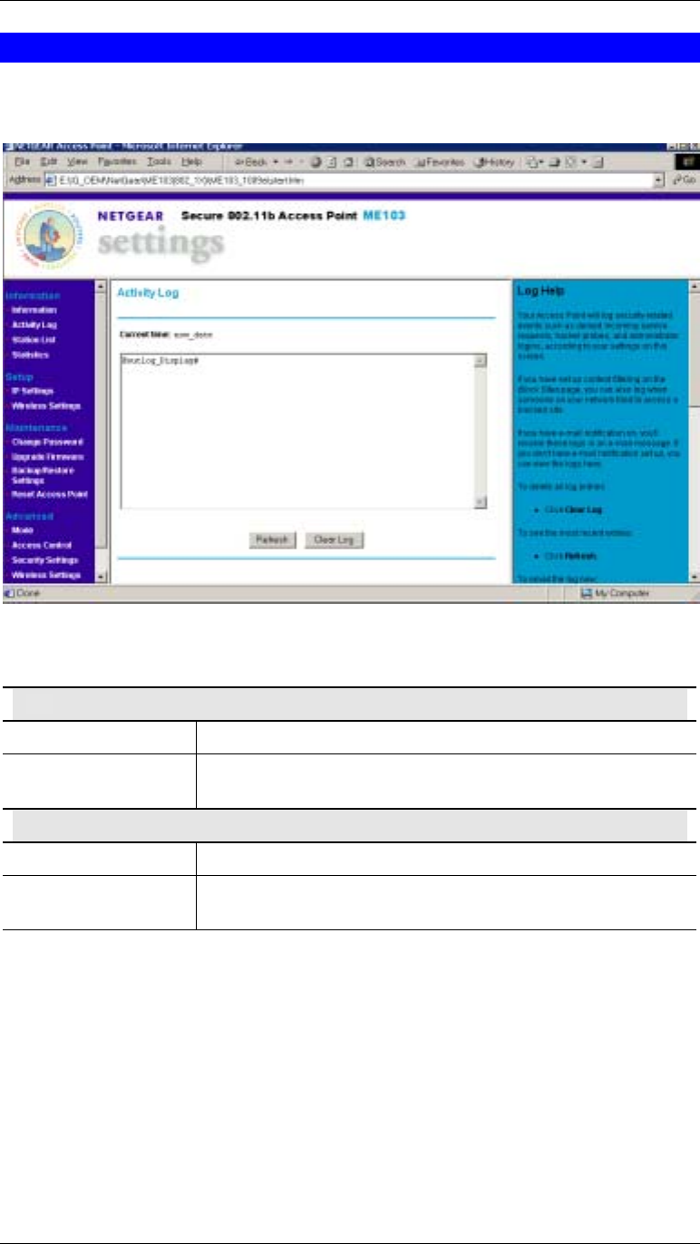
Activity Log
If using PPPoE (PPP over Ethernet), a screen like the following example will be displayed
when the "Connection Details" button is clicked.
Figure: Activity Log
Activity Log
Data
Current Time The system date and time is displayed.
Log The Log shows details of the existing connections to the Wireless
Access Point.
Buttons
Refresh Update the data on screen.
Clear Log This will delete all data currently in the Log. This will make it
easier to read new messages.
Wireless Access Point User Guide
24
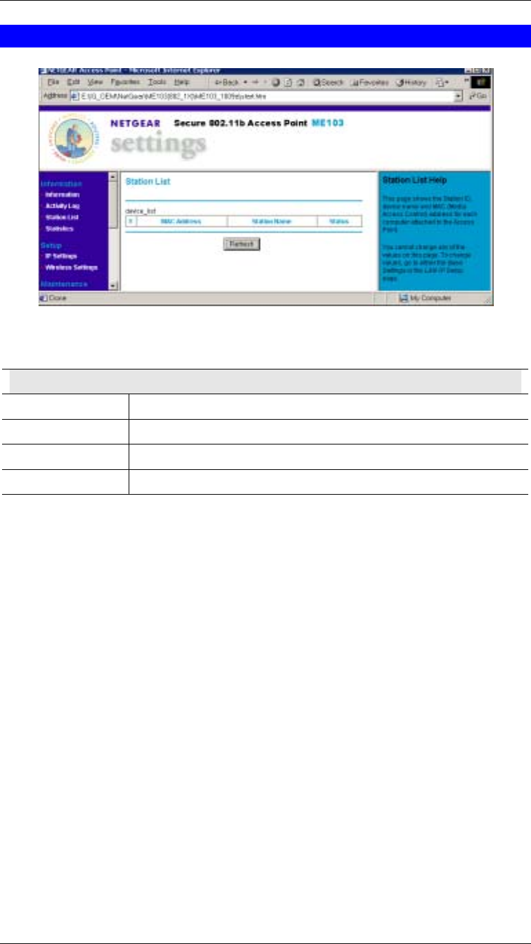
Station List
Figure 16 Station List Screen
Station List Screen
Station List
MAC Address The MAC (physical) address of each Wireless Station is displayed.
Station Name The name of each Wireless Station.
Status The current status of each Wireless Station is displayed.
Refresh Button Update the data on screen.
Operation and Status
25
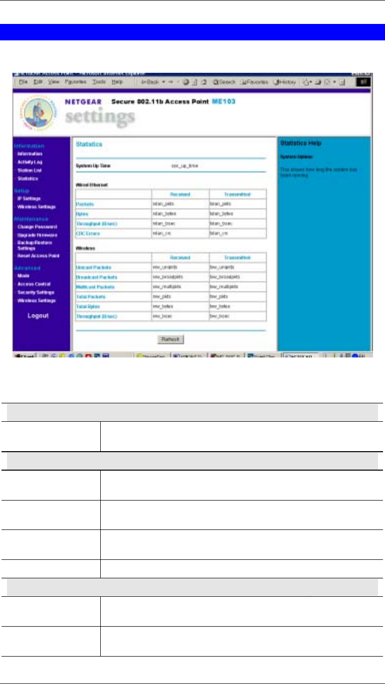
Statistics Screen
The Statistics screen shows details of the traffic flowing through the Wireless Access Point.
Figure 17: Statistics Screen
Data - Statistics Screen
System Up Time
System Up Time This indicates how long the system has been running since the last
restart or reboot.
Wired Ethernet
Packets Number of packets transmitted and received via the Wired Ethernet
port.
Bytes Number of bytes transmitted and received via the Wired Ethernet
port.
Throughput (Back) The throughput of data transmitted or received via the Wired
Ethernet port.
CRC Errors
Wireless
Unicast Packets Number of packets sent or received, when the communication was
to a single Wireless Station.
Broadcast Packets Number of Broadcast packets transmitted to and received from
Wireless Stations.

Wireless Access Point User Guide
26
Multicast Packets Number of Broadcast packets transmitted to and received from
Wireless Stations, using Multicast transmission.
Total Packets Total number of packets transmitted or received.
Total Bytes Total number of Bytes transmitted or received.
Throughput (B/sec) Throughput, measured in Bytes per second.
Refresh Button Update the data shown on screen.

Chapter 6
Other Settings & Features
This Chapter explains when and how to use the Wireless Access Point's
"Advanced" Features.
Overview
This Chapter covers the following features.
Maintenance
• Upgrade Firmware
• Backup/Restore Settings
• Reset Access Point
Advanced
• Access Control
• Wireless Settings
Upgrade Firmware
The firmware (software) in the Wireless Access Point can be upgraded using your Web
Browser.
You must first download the upgrade file, and then select Upgrade Firmware in the
Maintenance section of the menu. You will see a screen like the following.
Figure 18: Upgrade Firmware
6
Wireless Access Point User Guide
28
To perform the Firmware Upgrade:
9. Click the Browse button and navigate to the location of the upgrade file.
10. Select the upgrade file. Its name will appear in the Upgrade File field.
11. Click the Upload button to commence the firmware upgrade.
The Wireless Access Point is unavailable during the
upgrade process, and must restart when the
upgrade is completed. Any connections to or
through the Wireless Access Point will be lost.
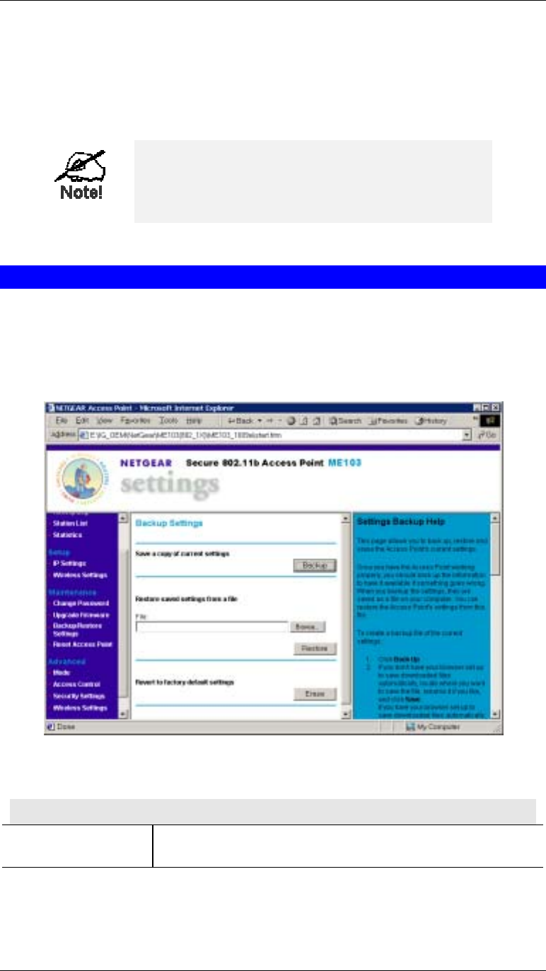
Backup/Restore Settings
This screen allows you to Backup (download) the configuration file, and to restore (upload) a
previously-saved configuration file.
You can also set the Wireless Access Point back to its factory default settings.
To reach this screen, select Upgrade Firmware in the Maintenance section of the menu.
Figure 19: Backup/Restore Settings
Backup/Restore Settings
Backup Setting
Save a copy of
current settings Click the Backup button to download the current settings to a file
on your PC.
Advanced Configuration
29
Restore saved settings
from a file If you have a previously-saved configuration file, you can use
this to restore those settings by uploading the file.
1. Click the Browse button and navigate to the location of the
configuration file.
2. Select the upgrade file. Its name will appear in the File field.
3. Click the Restore button to commence the upload.
4. The Wireless Access Point will need to restart, and will be
unavailable during the restart. All exiting connections will be
broken.
Revert to factory
default settings Use this to set the Wireless Access Point back to its factory
default settings.
• Click “Erase” to start the procedure.
• The Wireless Access Point will need to restart, and will be
unavailable during the restart. All exiting connections will be
broken.
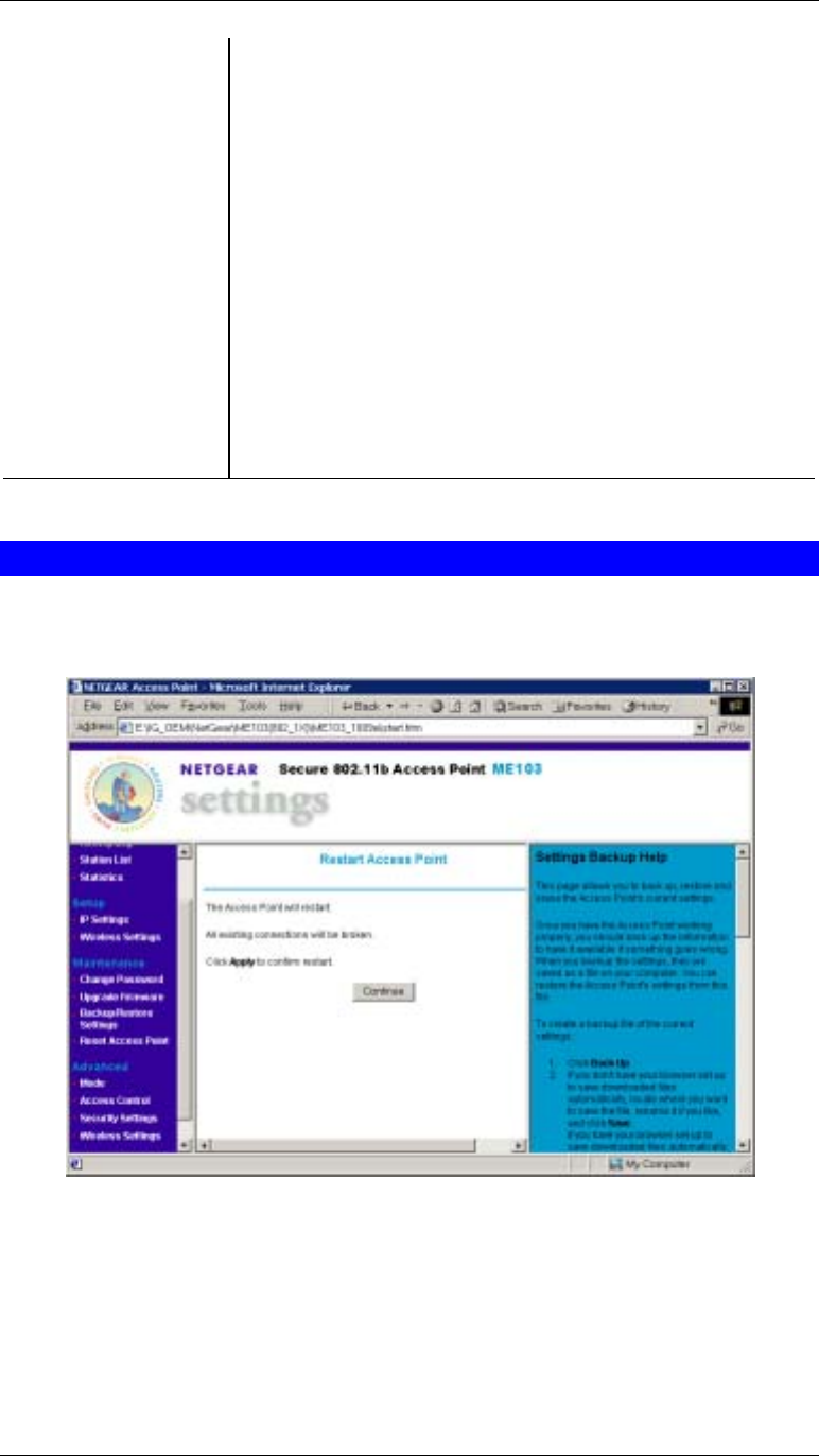
Reset Access Point
This screen allows you to Restart (Reboot) the Wireless Access Point.
To reach this screen, select Reset Access Point in the Maintenance section of the menu.
Figure 20: Reset Access Point
Wireless Access Point User Guide
30
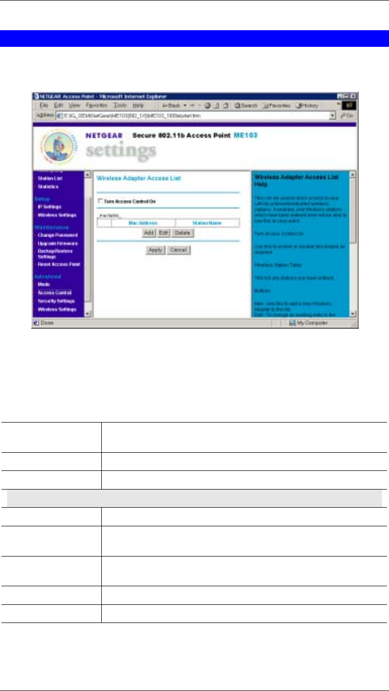
Access Control
The Access Control feature allows administrators to prevent “unknown” Wireless stations
from using the Access Point.
Figure 21: Access Control Screen
This screen is accessed by the Access Control link in the Advanced section of the menu.
The Table shows all “Known” (Trusted) wireless stations. If Access Control is enabled, only
these stations can use the Access Point.
Access Control Screen
Turn Access
Control On Check this box to enable the Access Control feature.
Mac Address For each Wireless station, the MAC (physical) address is shown.
Station Name The name of each Wireless station is shown.
Buttons
Add Add a new Wireless station to the list.
Edit Edit an existing Wireless Station. You need a select a station, using
the radio buttons on the left.
Delete Deleted an existing Wireless Station. You need a select a station,
using the radio buttons on the left.
Apply Save the settings on this screen.
Cancel Reverse any settings made since the last save.
Advanced Configuration
31
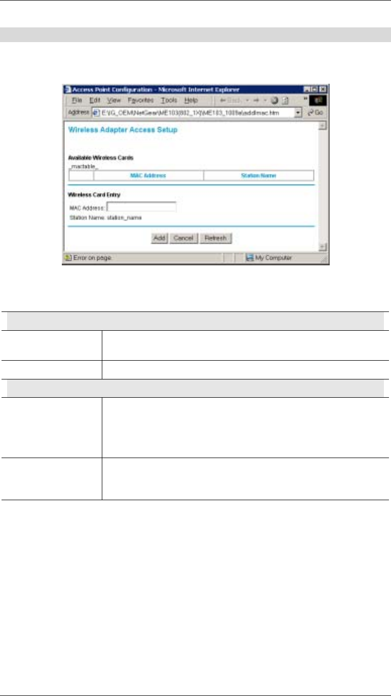
Wireless Adapter Access Setup
This screen is displayed when the Add button on the Wireless Adapter Access List screen is
clicked.
Figure 22: Wireless Adapter Access Setup
Wireless Adapter Access Setup
Available Wireless Cards
Mac Address For each available Wireless station, the MAC (physical) address is
shown.
Station Name The name of each Wireless station is shown.
Wireless Card Entry
MAC Address If you select a known Wireless Station (by clicking on the radio
button on the left), its MAC address will be inserted in this field.
If the Wireless station is not shown, you can enter its MAC address
in this field.
Station Name The name of each Wireless station will be automatically
determined when the Station connects to the Access Point. You do
not need to input the name.
Wireless Access Point User Guide
32
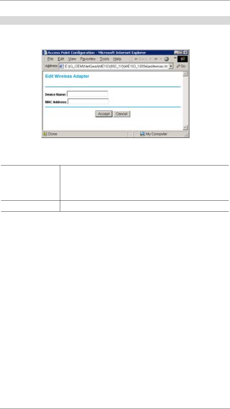
Edit Wireless Adapter
This screen is displayed when the Edit button on the Wireless Adapter Access List screen is
clicked.
Figure 23: Group Members
Edit Wireless Adapter
Device Name The name of each Wireless station will be automatically
determined when the Station connects to the Access Point. If this
fails, the name will be shown as “Unknown”.
Here, you can input the correct name.
MAC Address Enter the Wireless Station’s MAC address in this field.
Appendix A
Specifications
Wireless Access Point
CPU TI TNETW5305
DRAM 4 Mbytes (Can Expand)
Flash 1 Mbytes (Can Expand)
LAN port 1 x Shield RJ 45 for 10/100Mbps Ethernet
Wireless MAC&BB TI ACX100
Operating temp. 0~40℃
Storage temp -20℃70℃
Power Adapter DC 12V/800mA-1000mA
Dimension 7.45’ (W) x 4.85’ (D) x 1.06’ (H)
Wireless Specification
Receive Sensitivity at 11Mbps min. -85dBm
Receive Sensitivity at 5.5Mbps min. -89dBm
Receive Sensitivity at 2Mbps min. -90dBm
Receive Sensitivity at 1Mbps min. -93dBm
Maximum Receive Level min. -5dBm
Transmit Power 18 dBm
Modulation Direct Sequence Spread Spectrum BPSK / QPSK
/ CCK
Throughput Up to 4 Mbps
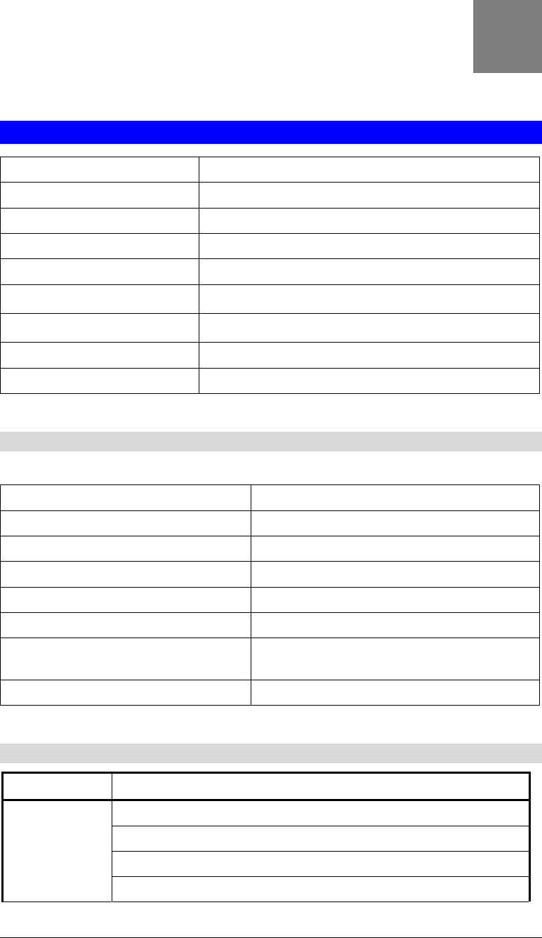
Software Specification
Feature Additional Information
Access point supported
IEEE 802.11b compliance
1M, 2M, 5.5M, 11Mbps support
Wireless
5 domain supports
A

Wireless Access Point User Guide
34
Bit error rate: 1E-5 @ -83dBm
WEP 64 bit and 128 bit security supported
30M(100ft.) @ 11Mbps
50M(165ft.) @ 5.5Mbps
70M(230ft.) @ 2Mbps
Indoors
91M(300ft.) @ 1Mbps
152M(500ft.) @ 11Mbps
270M(885ft.) @ 5.5Mbps
396M(1300ft.) @ 2 Mbps
Outdoors
457M(1500ft.) @ 1 Mbps
Management Web based configuration
Fully compatible with the IEEE 802.11b Standard
Network Mode: Infrastructure
Wireless Mac authentication
Enable/Disable SSID broadcast
Preamble Type
RTS Threshold
Fragmentation Threshold
Open system and shared key authentication support
64 bit (40 bit) & 128 bit WEP encryption
Adjustable Transmit power
System log
Attached station list
Automatic Channel Selections
802.1x support
Configuration file Backup
DHCP Client
WINS client
Radius client
NetBIOS name resolution
EAP-MD5 support
Functionality
EAP-TLS support
Firmware
Upgrade
HTTP, TFTP and proprietary network protocol download
FCC Statement
This equipment has been tested and found to comply with the limits for a Class B digital
device, pursuant to Part 15 of the FCC Rules. These limits are designed to provide reasonable
protection against harmful interference in a residential installation.
This equipment generates, uses and can radiate radio frequency energy and, if not installed and
used in accordance with the instructions, may cause harmful interference to radio
communications. However, there is no guarantee that interference will not occur in a particular
installation. If this equipment does cause harmful interference to radio or television reception,

Appendix A - Troubleshooting
35
which can be determined by turning the equipment off and on, the user is encouraged to try to
correct the interference by one of the following measures:
• Reorient or relocate the receiving antenna.
• Increase the separation between the equipment and receiver.
• Connect the equipment into an outlet on a circuit different from that to which the receiver
is connected.
• Consult the dealer or an experienced radio/TV technician for help.
To assure continued compliance, any changes or modifications not expressly approved by the
party responsible for compliance could void the user's authority to operate this equipment.
(Example - use only shielded interface cables when connecting to computer or peripheral
devices).
FCC Radiation Exposure Statement
This equipment complies with FCC RF radiation exposure limits set forth for an uncontrolled
environment. This equipment should be installed and operated with a minimum distance of 20
centimeters between the radiator and your body.
This device complies with Part 15 of the FCC Rules. Operation is subject to the following two
conditions:
(1) This device may not cause harmful interference, and
(2) this device must accept any interference received, including interference that may cause
undesired operation.
This transmitter must not be co-located or operating in conjunction with any other antenna or
transmitter.
Warning!
The case contains no user-serviceable components. Only qualified service staff should open
the case.

Appendix B
Troubleshooting
Overview
This chapter covers some common problems that may be encountered while using the Wireless
Access Point and some possible solutions to them. If you follow the suggested steps and the
Wireless Access Point still does not function properly, contact your dealer for further advice.
General Problems
Problem 1: Can't connect to the Wireless Access Point to configure it.
Solution 1: Check the following:
• The Wireless Access Point is properly installed, LAN connections are
OK, and it is powered ON. Check the LEDs for port status.
• Ensure that your PC and the Wireless Access Point are on the same
network segment. (If you don't have a router, this must be the case.)
• If your PC is set to "Obtain an IP Address automatically" (DHCP
client), restart it.
• If your PC uses a Fixed (Static) IP address, ensure that it is using an IP
Address within the range 192.168.254.1 to 192.168.254.253 and thus
compatible with the Wireless Access Point's default IP Address of
192.168.0.1.
Also, the Network Mask should be set to 255.255.255.0 to match the
Wireless Access Point.
In Windows, you can check these settings by using Control Panel-
Network to check the Properties for the TCP/IP protocol.
Internet Access
Problem 1: When I enter a URL or IP address I get a time out error.
Solution 1: A number of things could be causing this. Try the following troubleshooting
steps.
• Check if other PCs work. If they do, ensure that your PCs IP settings
are correct. If using a Fixed (Static) IP Address, check the Network
Mask, Default gateway and DNS as well as the IP Address.
• If the PCs are configured correctly, but still not working, check the
Wireless Access Point. Ensure that it is connected and ON. Connect to
it and check its settings. (If you can't connect to it, check the LAN and
power connections.)
• If the Wireless Access Point is configured correctly, check your Internet
connection (DSL/Cable modem etc) to see that it is working correctly.
B

Appendix A - Troubleshooting
37
Problem 2: Some applications do not run properly when using the Wireless Access
Point.
Solution 2: The Wireless Access Point processes the data passing through it, so it is not
transparent.
Use the Special Applications feature to allow the use of Internet applications
that do not function correctly.
If this does solve the problem you can use the DMZ function. This should
work with almost every application, but:
• It is a security risk, since the firewall is disabled for the DMZ PC.
• Only one (1) PC can use this feature.
Appendix C
Windows TCP/IP
Overview
Normally, no changes need to be made.
• By default, the Wireless Access Point will act as a DHCP client, automatically obtaining a
suitable IP Address (and related information) from your DHCP Server.
• If using Fixed (specified) IP addresses on your LAN (instead of a DHCP Server), there is
not need to change the TCP/IP of each PC. Just configure the Wireless Access Point to
match your existing LAN.
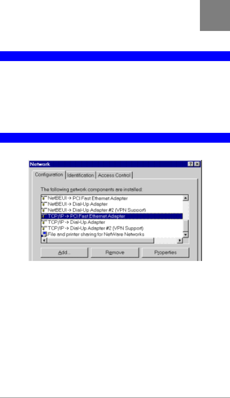
Checking TCP/IP Settings - Windows 9x/ME:
1. Select Control Panel - Network. You should see a screen like the following:
Figure 24: Network Configuration
2. Select the TCP/IP protocol for your network card.
3. Click on the Properties button. You should then see a screen like the following.
C
Appendix C - Specifications
39
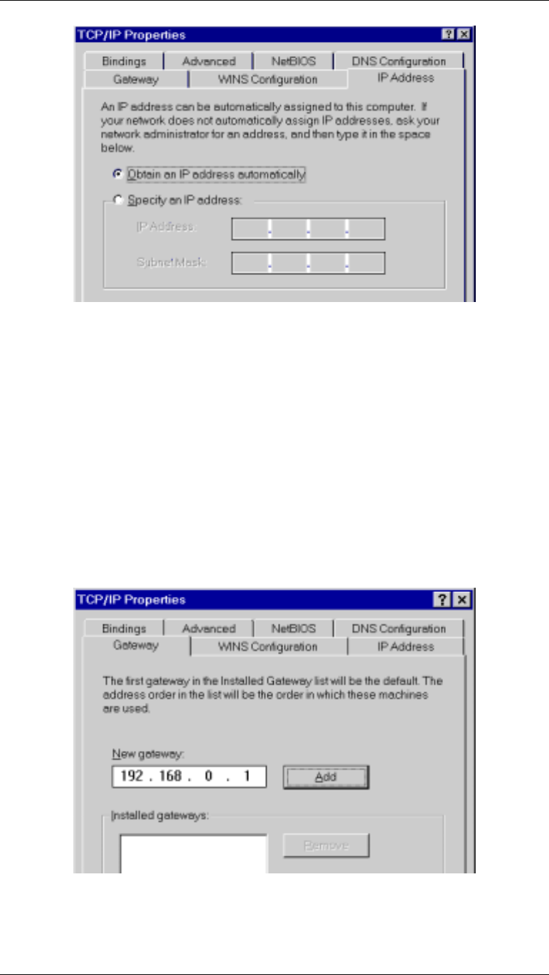
Figure 25: IP Address (Win 95)
Ensure your TCP/IP settings are correct, as follows:
Using DHCP
To use DHCP, select the radio button Obtain an IP Address automatically. This is the default
Windows settings.
Restart your PC to ensure it obtains an IP Address from the Wireless Access Point.
Using "Specify an IP Address"
• If your PC is already configured, do NOT change the settings on the IP Address tab shown
in Figure 25 above.
• On the Gateway tab, enter the Wireless Access Point's IP address in the New Gateway
field and click Add. Your LAN administrator can advise you of the IP Address they
assigned to the Wireless Access Point.
Figure 26: Gateway Tab
Wireless Access Point User Guide
40
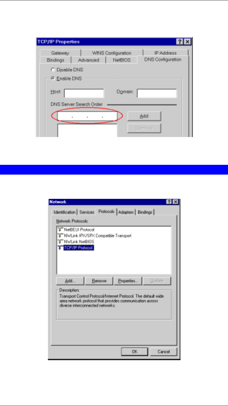
• On the DNS Configuration tab, ensure Enable DNS is selected. If the DNS Server Search
Order list is empty, enter the DNS address provided by your ISP in the fields beside the
Add button, then click Add.
Figure 27: DNS Tab (Win 95/98)
Checking TCP/IP Settings - Windows NT4.0
1. Select Control Panel - Network, and, on the Protocols tab, select the TCP/IP protocol, as
shown below.
Figure 28: Windows NT4.0 - TCP/IP
2. Click the Properties button to see a screen like the one below.

Appendix C - Specifications
41
Figure 29: Windows NT4.0 - IP Address
3. Select the network card for your LAN.
4. Select the appropriate radio button - Obtain an IP address from a DHCP Server or Specify
an IP Address, as explained below.
Obtain an IP address from a DHCP Server
This is the default Windows setting. Using this method is recommended. By default, the
Wireless Access Point will act as a DHCP Server.
Restart your PC to ensure it obtains an IP Address from the Wireless Access Point.
Specify an IP Address
If your PC is already configured, check with your network administrator before making the
following changes.
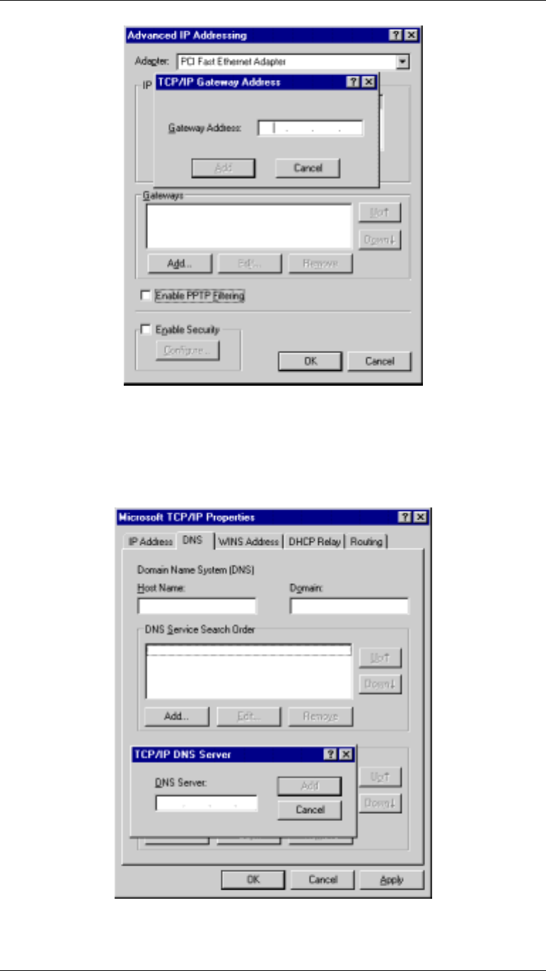
1. The Default Gateway must be set to the IP address of the Wireless Access Point. To set
this:
• Click the Advanced button on the screen above.
• On the following screen, click the Add button in the Gateways panel, and enter the
Wireless Access Point's IP address, as shown in Figure 30 below.
• If necessary, use the Up button to make the Wireless Access Point the first entry in
the Gateways list.
Wireless Access Point User Guide
42
Figure 30 - Windows NT4.0 - Add Gateway
2. The DNS should be set to the address provided by your ISP, as follows:
• Click the DNS tab.
• On the DNS screen, shown below, click the Add button (under DNS Service Search
Order), and enter the DNS provided by your ISP.
Figure 31: Windows NT4.0 - DNS
Appendix C - Specifications
43
Checking TCP/IP Settings - Windows 2000:
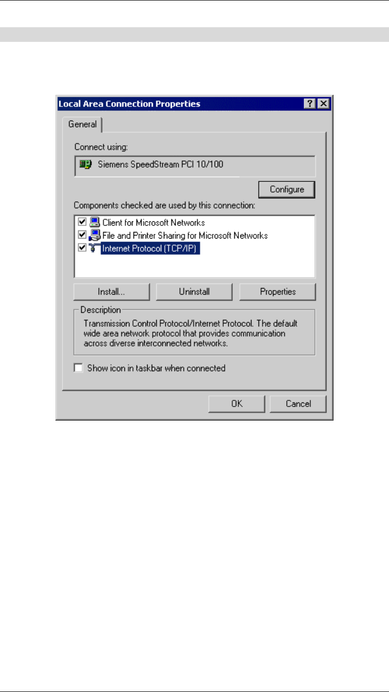
1. Select Control Panel - Network and Dial-up Connection.
2. Right click the Local Area Connection icon and select Properties. You should see a screen
like the following:
Figure 32: Network Configuration (Win 2000)
3. Select the TCP/IP protocol for your network card.
4. Click on the Properties button. You should then see a screen like the following.
Wireless Access Point User Guide
44
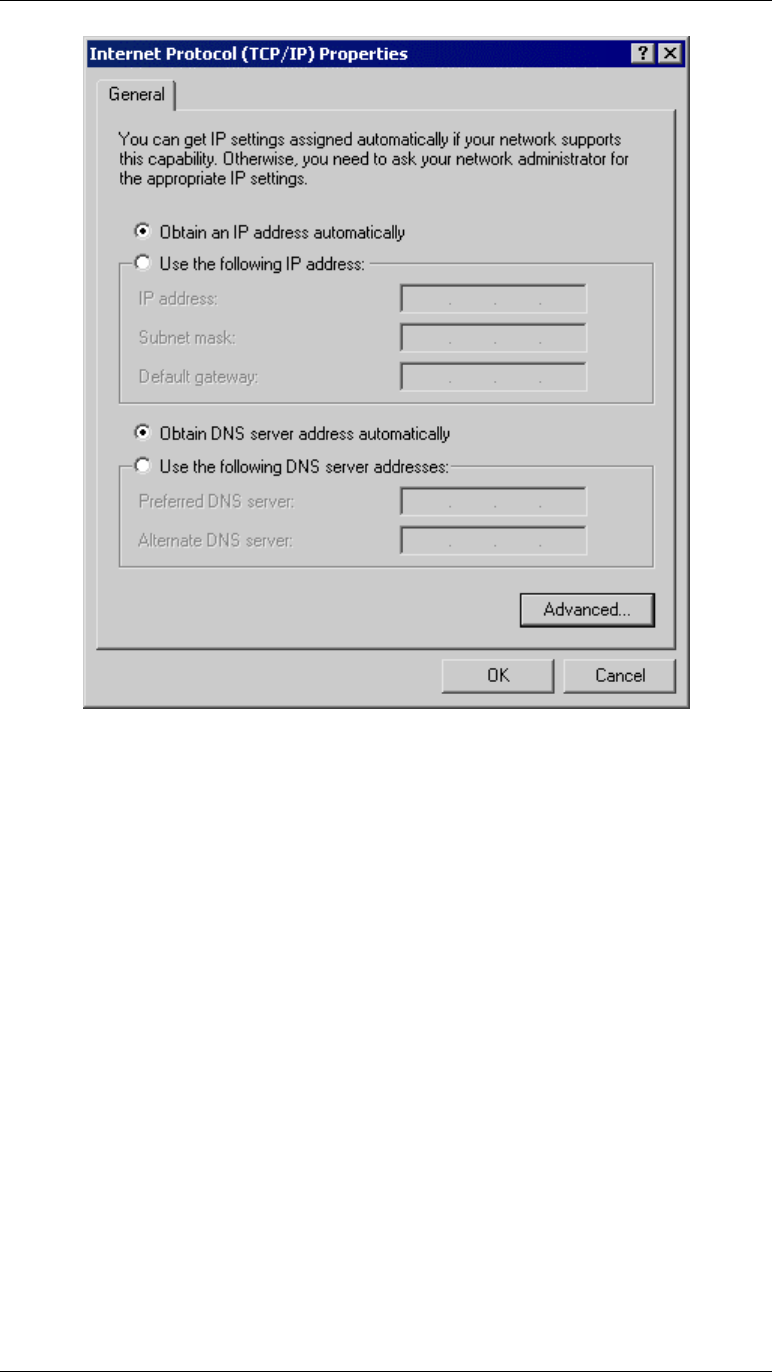
Figure 33: TCP/IP Properties (Win 2000)
5. Ensure your TCP/IP settings are correct:
Using DHCP
To use DHCP, select the radio button Obtain an IP Address automatically. This is the default
Windows settings.
Restart your PC to ensure it obtains an IP Address from the Wireless Access Point.
Using a fixed IP Address ("Use the following IP Address")
If your PC is already configured, check your ISP's documentation before making the following
changes.
• Enter the Wireless Access Point's IP address in the Default gateway field and click OK.
• If the DNS Server fields are empty, select Use the following DNS server addresses, and
enter the DNS address or addresses provided by your ISP, then click OK.
Appendix C - Specifications
45
Checking TCP/IP Settings - Windows XP:
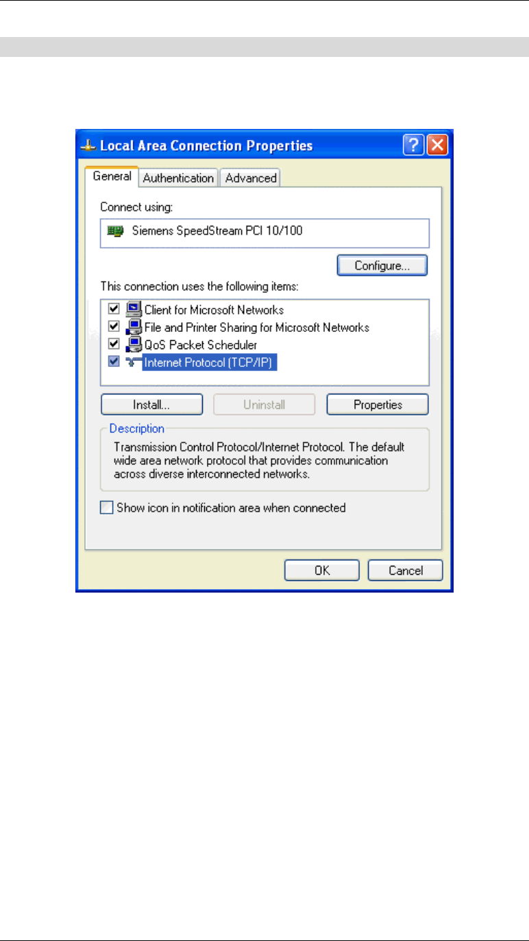
1. Select Control Panel - Network Connection.
2. Right click the Local Area Connection and choose Properties. You should see a screen
like the following:
Figure 34: Network Configuration (Windows XP)
3. Select the TCP/IP protocol for your network card.
4. Click on the Properties button. You should then see a screen like the following.
Wireless Access Point User Guide
46
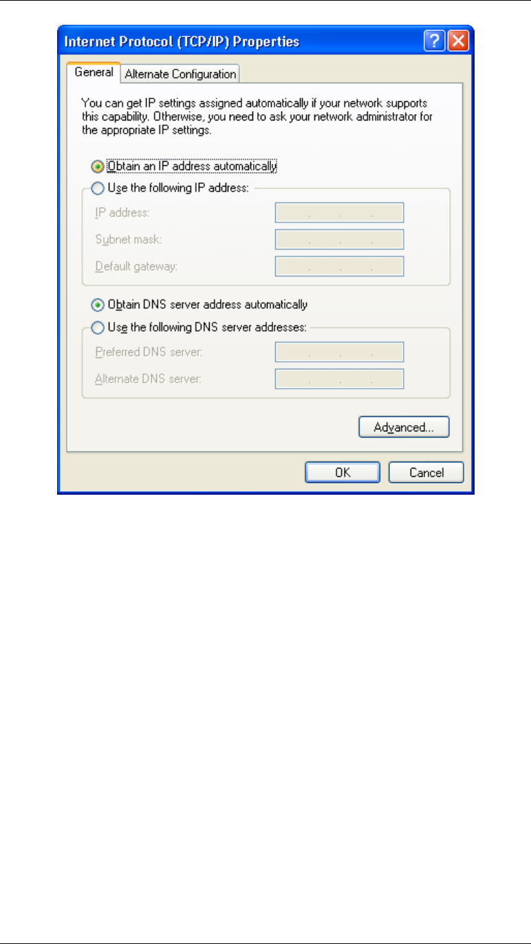
Figure 35: TCP/IP Properties (Windows XP)
5. Ensure your TCP/IP settings are correct.
Using DHCP
To use DHCP, select the radio button Obtain an IP Address automatically. This is the default
Windows settings.
Restart your PC to ensure it obtains an IP Address from the Wireless Access Point.
Using a fixed IP Address ("Use the following IP Address")
• If your PC is already configured, do NOT change the settings on the screen shown in
Figure 35 above, unless advised to do so by your network administrator.
• You can enter the Wireless Access Point's IP address in the Default gateway field and
click OK. Your LAN administrator can advise you of the IP Address they assigned to the
Wireless Access Point.
• If the DNS Server fields are empty, select Use the following DNS server addresses, and
enter the DNS address or addresses provided by your ISP, then click OK.