NeuroMetrix RF-SYNC ASCEND STIMULATOR/BIOAMPLIFIER User Manual
NeuroMetrix, Inc. ASCEND STIMULATOR/BIOAMPLIFIER Users Manual
Users Manual

DRAFT Page 1 of 32
NeuroMetrix
ASCEND
User’s Manual

DRAFT Page 2 of 32
Copyright © 2009 NeuroMetrix, Inc. All rights reserved.
No part of this document may be reproduced or transmitted in any form or by any means,
electronic or mechanical, for any purpose without the express written permission of NeuroMetrix,
Inc.
ASCEND™ and NeuroMetrix® are trademarks of NeuroMetrix, Inc. Waltham, MA 02451 USA
The Bluetooth® word mark and logos are owned by the Bluetooth SIG, Inc. and any use of such
marks by NeuroMetrix, Inc. is under license.
Part Number: PN 2202661 Rev. X16
Protected by US and international patents pending.
CAUTION: Federal law restricts the use of output of ASCEND to a physician
or other properly licensed practitioner.
.
DRAFT Page 3 of 32
Table of Contents
Chapter One – Indications for Use, Principles of Operation, ASCEND Description 4
Indications for use 4
Contraindications 4
Nerve Stimulation: Overview 4
Nerve Stimulation: Principles of Operation 5
ASCEND Description 5
Chapter Two – Preparing ASCEND for Use 8
Overview 8
Cradle Setup 8
Stimulator Setup 8
Registration 9
Chapter Three – User Interface and Controls 10
Overview 10
Control Button 10
Chapter Four – Device Description 14
Overview 14
Connecting Cables 14
Power On 14
Power Off 14
Stimulation Current 14
Stimulation Duration 15
Stimulation Frequency 15
Chapter Five – Device Checks 16
Overview 16
Power up self test 16
Stimulation Electrodes Connection Check 16
Check Stimulation High Voltage 16
Stimulation Circuitry check 16
Appendix A – Warranty, Service, Care and Device Registration 17
Cleaning 17
Warranty 17
Device Registration 19
Service 20
Appendix B – Error Messages, Warnings and Cautions 23
Appendix C – Specifications 27
Appendix D – Symbols and Acronyms 29
Appendix E – Accessories 31
Appendix F – Electromagnetic Compatibility Declaration 32

DRAFT Page 4 of 32
CHAPTER ONE
Indications for Use, Principle of Operations, ASCEND
Description
This manual is intended for users of the NeuroMetrix ASCEND Peripheral Nerve Stimulator
(“ASCEND”).
Indications For Use
NeuroMetrix ASCEND is a peripheral nerve stimulator used for localization and verification of
needle placement for perineural application of pharmacological agents.
Contraindications
Absolute and relative contraindications for using a peripheral nerve stimulator for percutaneous
nerve localization procedures using insulated hypodermic needles include:
• Refusal of regional anesthesia by the patient
• Infection at the puncture site
• Preoperatively known neurological dysfunctions
• Anatomical abnormalities
• Severe coagulation disorders
• Insufficient liver function
Nerve Stimulation: Overview
Peripheral nerve stimulation (PNS) facilitates the performance of peripheral nerve and plexus
blocks. Using nerve stimulation (NS), the physician does not need to rely on feedback from the
patient about paresthetic sensations. As a result, the danger of mechanical nerve lesions is
significantly diminished. When the stimulation needle is placed sufficiently close to the target
nerve, predefined electrical pulses evoke compound muscle action potentials (CMAP) and
consequent muscle contractions. During this procedure, direct contact of the injection needle with
the nerve is intentionally avoided.
NS is not a substitute for the anatomical knowledge required to perform regional anesthesia.
Therefore an accurate knowledge of the topography and nerve distribution area is essential.
The advantages of NS include:
• Muscle response is obtained without the user having to rely on information or
cooperation from the patient
• Reduction in probability of direct needle-nerve contact, painful paresthesias, mechanical
nerve lesions, and intraneural injections.
Nerve Stimulation: Principle of Operation
The resting potential at the nerve membrane is around 80 mV. The cell’s interior is negatively
charged compared to the surrounding medium. Sufficiently large ion movement reduces the
DRAFT Page 5 of 32
membrane potential to about 55 mV, making the membrane freely permeable and generating an
action potential.
The various types of nerve fiber differ with regard to their sensitivity to electrical stimulation.
The Aα motor fibers have the shortest chronaxia (50–100 μs). The afferent fibers that transmit
pain sensation (Aδ and C-fibers) require a longer pulse (150 and/or 400) at a minimum current.
Mixed peripheral nerves can be localized using short pulses (100 μs) without triggering pain
sensations. For pure sensory nerves, a longer pulse is recommended (200 μs, 500 μs or 1000 μs).
When unipolar needles (insulated and with conductive tip) are used, the current necessary to
trigger muscle responses correlates with the distance from the tip of the needle to the nerve. The
lower the current, the more accurately the target nerve can be localized. This allows quicker onset
and ensures a more reliable success of the blockade.
Nevertheless, it is important to observe and stay within the predefined threshold currents so as to
avoid a too close proximity to the nerve and prevent nerve damage. The shorter the electrical
pulse (i.e., stimulus duration), the faster is the rise in current to the nerve. This allows better
discrimination by the physician as to whether the needle tip is sufficiently close to the nerve. The
stimulation needle should always be connected to the negative pole. If the needle is connected to
the positive pole, higher currents are required. The conductive tip of the stimulation needle
affects the geometry of the electrical field. The smaller the emission site of the electrons at the tip
of the needle, the higher is the current density at this point and the lower the threshold level once
the nerve has been localized exactly.
DRAFT Page 6 of 32
ASCEND Description
ASCEND is a battery powered nerve stimulator for localization of peripheral nerves. It is
comprised of the following components.
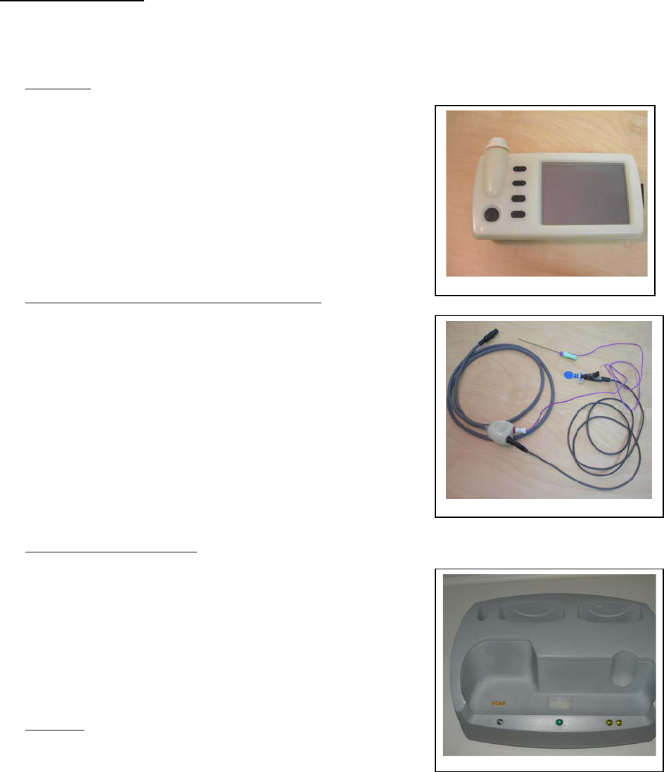
1. Stimulator
The Stimulator includes the electronic circuits that provide
electrical nerve stimulation, user controls which include a
stimulation current magnitude control and function buttons that
control stimulation parameters such as duration and frequency,
and a 320 by 240 color LCD touch screen for user input and
display of the target current, impedance and other important
parameters. The Stimulator includes a permanent 3.7V Li-
Polymer battery. The stimulator has a connector to a needle
and electrode interface cable as well as a micro USB port.
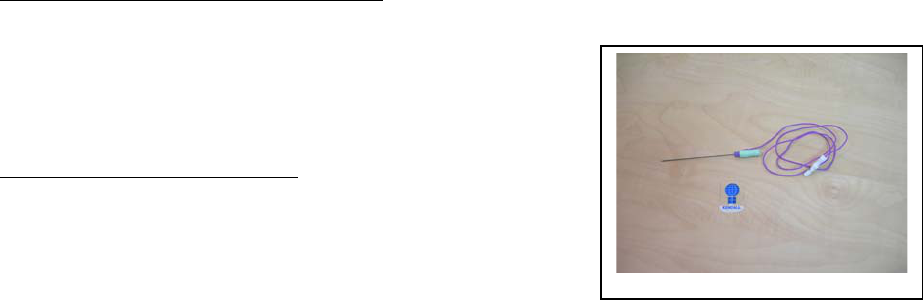
2. Needle and Electrode Interface Cable (“Cable”)
The Cable provides an interface between the Stimulator and the
insulated hypodermic needles and surface electrodes used in
nerve localization procedures. One end of the Cable plugs into
connector on the top of Stimulator. The other end of the
connector ends in yoke with two connectors: one into which a
needle with a pre-attached leads is connected and one into
which a cable terminating in an alligator clip is connected (the
alligator clip is then attached to a disposable surface electrode).
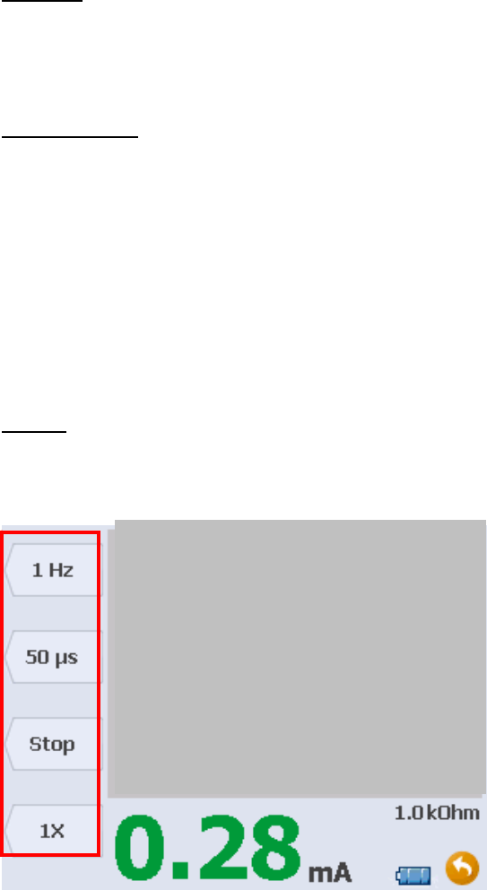
3. Charging Cradle (“Cradle”)
The Cradle is connected to an AC outlet via a medical grade
AC/DC adapter. The Cradle has LEDs that indicate its on/off
status and the charging/charge status of Stimulator (see Chapter
2 for a description of the Cradle LED indicator).
4. USB port
The USB port is for programming and communication.
Stimulation is disabled and cannot be performed when the USB
port is connected
Figure 1
Figure 2
Fi
g
ure 3
DRAFT Page 7 of 32
ASCEND may be used with the following accessories.
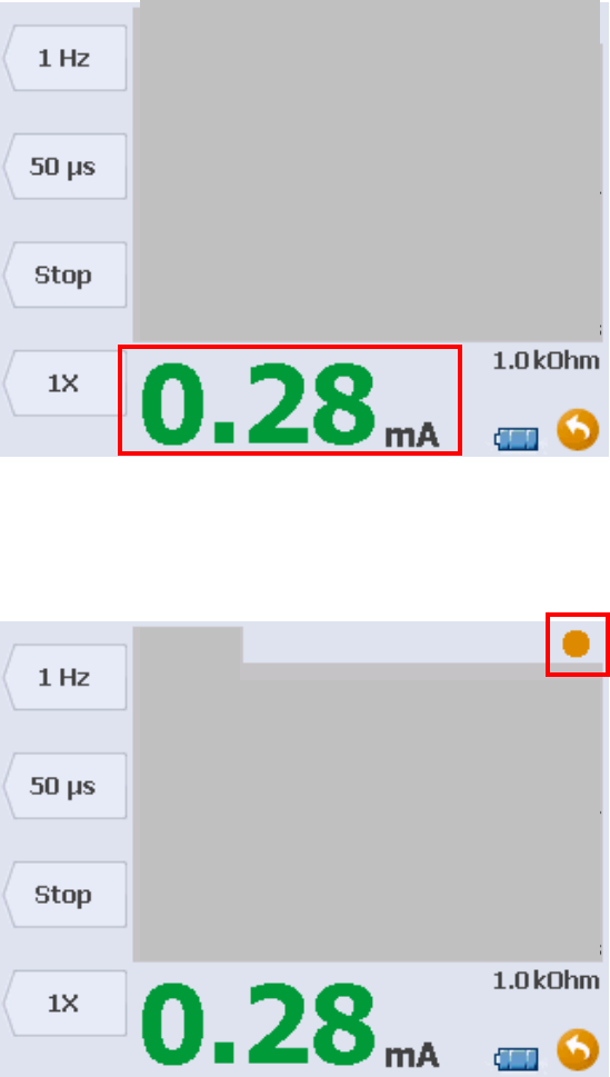
1. Hypodermic Insulated Needles (“Needles”)
ASCEND is optimized for nerve localization procedures using
disposable hypodermic needle electrodes distributed by
NeuroMetrix. These needles typically serve as the stimulation
cathode.
2. Surface Electrodes (“Electrodes”)
ASCEND utilizes a disposable tab surface electrode as the
stimulation anode. ASCEND can be used with any suitable
disposable surface electrode.
Figure 4

DRAFT Page 8 of 32
CHAPTER TWO
Preparing ASCEND for Use
Overview
Prior to use, the ASCEND Stimulator, Cradle, and other packaged components should be
inspected to ensure that they have not been damaged in shipping. If damage is encountered, or if
any component fails to operate as described in this manual, contact NeuroMetrix Customer
Service immediately. Within the USA, customers should contact NeuroMetrix via:
Phone: 1-888-786-7287
Fax: (781) 890-1556
Email: service@neurometrix.com
International customers should contact the nearest authorized NeuroMetrix representative. If the
shipping container is damaged, customers should also notify the shipping carrier.
The ASCEND system package should contain the following components:
Installation Card
User’s Manual
Stimulator
Cable
Cradle
Power Supply for Cradle
Operating software is pre-installed in the device before it is shipped from the factory.
Cradle Setup
Before use, visually inspect the Cradle. Make sure that the Cradle’s plastic housing is
undamaged. The Cradle should then be plugged into a power outlet using the medical grade
power supply provided.
Stimulator Setup
Before use, visually inspect the Stimulator. Make sure wire insulation is intact and that the
plastic housing of the device is undamaged. Place the Stimulator in the Cradle to charge its
internal battery. Charge the battery for a minimum of 6 hours. When an incompletely charged
Stimulator is placed in the Cradle, the Stimulator charge status LED will display an amber light; a
green light signifies a fully charged battery.
Once the Stimulator battery is charged, power up the Stimulator by pressing the POWER button.
After the Stimulator powers up, it will conduct a self test. Once completed, the LCD will display
the START screen. If the device fails the self test, the device will disable the stimulator circuit, and
the LCD will display the message STIMULATOR ERROR . If the Stimulator fails to power up when
the power button is pressed, confirm that the battery is fully charged and try again. If the
Stimulator fails to power up again, please contact Customer Service.

DRAFT Page 9 of 32
Registration
NeuroMetrix Customer Service will register your system at the time of installation.
DRAFT Page 10 of 32
CHAPTER THREE
User Interface and Controls
Overview
This section describes the Stimulator User Interface. Physical buttons are indicated in bold blue.
On screen buttons, which are activated by tapping the touch screen with the stylus, are indicated
in bold green. On screen messages are indicated in orange.
Control Buttons
POWER – powers Stimulator on and off.
FUNCTION – the Stimulator has four context sensitive function buttons along the left side of the
device (Chapter 1, Figure 1). The button’s current function is indicated on the screen to the right
of the button. (Figure 6, red rectangle). The function of these buttons varies depending upon the
Stimulator’s operating mode and can change within an operating mode.
DIAL – regulates the target stimulation current.
RESET – resets Stimulator.
Screens
The Stimulator has one screen from which the operator controls the device. In this screen
the operator controls nerve stimulation.
Figure 6 – Stimulation Control Screen
In the Stimulation Control Screen, (Figure 6), the four function buttons described above have the
following functions. The top button controls stimulation frequency. Values of Single, 1Hz or 2
Hz may be selected. The second button controls stimulus duration. Values of 50, 100, 200, 500,
DRAFT Page 11 of 32
1000 µsec may be selected. The third button starts and stops stimulation. The bottom button is
reserved for future use.
Figure 7 – Patient Stimulation Current Indicator
The patient stimulation current indicator (Figure 7, red rectangle) shows the current delivered to
the patient.
Figure 8 – Stimulus Indicator
The stimulus indicator (Figure 8, red rectangle) blinks when a stimulus is delivered. The color of
the indicator is:
• Green, when the patient current is above the threshold current and is within the tolerance
(see Appendix B) of the target current.
DRAFT Page 12 of 32
• Orange, when the patient current is equal to or less than the threshold current and is
within the tolerance of the target current.
• Red when the patient current is out of the tolerance of the target current.
• Gray and steady when no stimulus is being delivered.
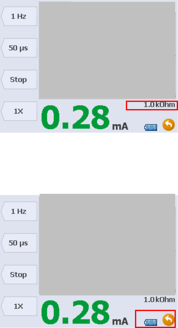
Figure 9 – Impedance Display
The impedance display (Figure 9, red rectangle) indicates the impedance in kOhm between the
needle and the return electrode (anode). The target stimulation current will also be shown if the
patient delivered current is out of tolerance.
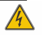
Figure 10 – Battery Fuel Gauge & Back Arrow
DRAFT Page 13 of 32
This bottom right corner of the screen (Figure 10, red rectangle) shows the battery fuel gauge and
the back arrow to return the operator to the main screen.

DRAFT Page 14 of 32
CHAPTER FOUR
Device Operation
Overview
This chapter describes basic operation of ASCEND.
The operator should verify that all ASCEND components are in a serviceable condition before
each use. Defective components should not be used. The equipment may only be repaired by
NeuroMetrix. Please contact customer service at 1-888-786-7287 if you have any concerns
regarding the device.
Connecting Cables
Connect the stimulation cable to the device.
Connect an appropriately sized NeuroMetrix hypodermic needle to the stimulation cable yoke
(black jack) See Appendix F for list and ordering instructions.
Connect the surface electrode (anode) lead wire to the stimulation cable yoke (red jack).
Power On
Press the POWER button.
Upon power up, a self-test will be performed (see Chapter 5 for a detailed description). If the
self-test fails then an audible alarm will sound and a text message (see Appendix B for a detailed
description) will appear on the screen. Stimulation is disabled if the self test fails.
Power Off
Press the POWER button.
Stimulation Current
The magnitude of the target stimulation current level is set using the DIAL. The target current is
set to 0.00 mA on power up and may range from 0.00 to 5.00 mA. The resolution of the current
increments varies according to the current level as shown below.
Target Current
Range
Target Current
Increments
0.0 – 0.1 mA 0.01 mA
0.1 – 0.5 mA 0.02 mA
0.5 – 2.0 mA 0.1 mA
2.0 – 5 mA 0.25 mA

DRAFT Page 15 of 32
Stimulus Duration
The stimulus duration is set by pressing the DURATION button. Each time this button is
pressed it will change the duration to the next value in the following repeating sequence: 50 μsec,
100 μsec, 200 μsec, 500 μsec, 1000 μsec. On power up the duration is set to 100 μsec.
Stimulation Frequency
The stimulation frequency is set by pressing the FREQUENCY button. Each time this button is
pressed it will change the frequency to the next value in the following repeating sequence: 1 Hz, 2
Hz, Single. On power up the frequency is set to 1 Hz.
When the stimulation frequency is set to Single, the device does not automatically stimulate the
nerve. A single stimulus will be generated whenever the TRIGGER button is pressed.
There are a number of ways for the operator to stop stimulation:
• Press STOP button when stimulating in 1 Hz or 2 Hz modes.
• Decrease the stimulation current to 0 mA with the control dial.
• Withdraw the needle. If the needle is withdrawn, no current will be delivered to patient.
• Disconnect the needle lead wire from the stimulator cable yoke.
• Power Stimulator off.

DRAFT Page 16 of 32
CHAPTER FIVE
Device Checks
Overview
If the Stimulator and its accessories parts do not function as described below, please contact
customer service at 1-888-786-7287 for assistance.
Power up self test
When the application starts, the device will perform the following self test:
Check power supplies
Check stimulation circuit
Check CPU memory
Check MSP ADC
Stimulating Electrodes Connection Check
Unplug the needle or the stimulation surface electrode and increase the stimulation current using
the DIAL from 0 to 0.05 mA. 0.00mA is displayed in orange color, the stimulus indicator blinks
in red color, and the audio alarm sounds, and the impedance is out of range (too high).
Check Stimulation High Voltage
The stimulation high voltage is verified by the Stimulator. If the voltage does not reach the
minimum acceptable level (81 volts), the test is halted and a “Stim Aborted Code: 0x0021” error
message displayed. In the event of this error, the user should recharge the battery. If the same
error message occurs following battery recharging, contact NeuroMetrix Customer Service to
arrange for device servicing.
Stimulation Circuitry Check
The device performs a power-up self-check on the stimulation circuitry by delivering a stimulus
to an internal resistor (10 kOhm). If the delivered current magnitude is not within tolerance of the
target current, the test is halted and a “Stim Aborted Code: 0x0061” message will be displayed.
The device should be returned to NeuroMetrix for service.
See Appendix B for a description of the error descriptions, codes, warnings and cautions.

DRAFT Page 17 of 32
APPENDIX A
Warranty, Service, Care, and Device Registration
The ASCEND system has been manufactured to the highest quality standards. To ensure
continued trouble-free operation, avoid exposure to excessive shock, vibration, or moisture.
Particular care should be taken to protect the Cable. To clean the Stimulator and Charger, observe
the following guidelines:
Use a soft damp cloth or sponge to clean the exterior of the unit.
Insure no water penetrates the devices
Use only wipes for disinfection, no spray should be used (to avoid condensation)
Methanol free substances should be used for disinfection.
Caution! Do not use abrasive cleaners or strong solvents to clean the device.
Under no circumstance should the LCD screen be touched with any object other than the
supplied stylus.
The ASCEND system is designed to be used in a clinical environment. Proper care should be
used when maintaining these components. Inspect all parts for any visible damage. Never use
any damaged or modified parts!
Electrode/Needle Disposal
Used stimulation needles and surface electrodes should be discarded in accordance with national,
regional, and local regulations. The used needles are considered biohazardous waste and should
be discarded in a suitable biohazardous waste container (sharps).
Coverage during the Warranty Period
During the 1 year period beginning on the invoice date, NeuroMetrix, Inc. will repair or replace
products covered under this limited warranty that are returned to NeuroMetrix, Inc. or an
authorized service facility. To request warranty service, you must call the NeuroMetrix Customer
Service department within the warranty period. If warranty service is required, NeuroMetrix will
issue a Return Material Authorization number. You must ship the products back to NeuroMetrix
in the original or equivalent packaging, prepay shipping charges, and insure the shipment, or
accept the risk of loss or damage during shipment. NeuroMetrix will ship the repaired or
replacement products to you freight prepaid to U.S. or Canadian addresses. Shipments to other
locations will be made freight collect.
DRAFT Page 18 of 32
NeuroMetrix, Inc. Limited One Year Warranty
NeuroMetrix, Inc. manufactures its hardware products from new components in accordance with industry
standard practices. NeuroMetrix, Inc. warrants the ASCEND System to be free from defects in materials
and workmanship. The warranty term is one year beginning on the date of invoice, as described in the
following text.
Damage due to shipping the products is covered under this warranty. Otherwise, this warranty
does not cover damage due to external causes, including accident, abuse, misuse, problems with electrical
power, servicing not authorized by NeuroMetrix, Inc., usage not in accordance with product instructions,
failure to perform required preventive maintenance, and problems caused by use of parts and components
not supplied by NeuroMetrix, Inc.
This warranty does not cover any items that are in one or more of the following categories:
software, external devices (except as specifically noted) or accessories or parts added to a NeuroMetrix
system through authorized NeuroMetrix service centers.
NeuroMetrix, Inc. will repair or replace products covered under this limited warranty that are
returned to NeuroMetrix’s facility or an authorized NeuroMetrix representative. To request warranty
service, you must call the NeuroMetrix Customer Service Department or an authorized technical support
representative within the warranty period. NeuroMetrix will issue a Return Material Authorization Number.
The product must be shipped to NeuroMetrix in the original or equivalent packaging with prepaid shipping
charges and insured against loss or damage during shipment. NeuroMetrix will ship the repaired or
replacement units to the originator (freight prepaid) to addresses within the US or Canada. Shipments to
other locations will be made freight collect.
All parts removed from repaired products will become the property of NeuroMetrix, Inc. If
NeuroMetrix repairs or replaces a product, the original warranty is not extended.
NEUROMETRIX, INC. MAKES NO EXPRESS WARRANTIES OR CONDITIONS BEYOND
THOSE STATED IN THIS WARRANTY STATEMENT. NEUROMETRIX DISCLAIMS ALL OTHER
WARRANTIES AND CONDITIONS, EXPRESS OR IMPLIED, INCLUDING WITHOUT LIMITATION
IMPLIED WARRANTIES AND CONDITIONS OR MERCHANTABILITY AND FITNESS FOR A
PARTICULAR PURPOSE. SOME STATES (OR JURISDICTIONS) DO NOT ALLOW LIMITATIONS
ON IMPLIED WARRANTIES OR CONDITIONS, SO THIS LIMITATION MAY NOT APPLY TO
YOU.
NEUROMETRIX RESPONSIBILITY FOR MALFUNCTIONS AND DEFECTS IN
HARDWARE IS LIMITED TO REPAIR AND REPLACEMENT AS SET FORTH IN THIS
WARRANTY STATEMENT. THESE WARRANTIES GIVE YOU SPECIFIC LEGAL RIGHTS IN
ADDITION TO OTHER RIGHTS WHICH VARY FROM STATE TO STATE.
NEUROMETRIX INC. DOES NOT ACCEPT LIABILITY BEYOND THE REMEDIES SET
FORTH IN THIS WARRANTY STATEMENT OR LIABILITY FOR INCIDENTAL OR
CONSEQUENTIAL DAMAGES, INCLUDING WITHOUT LIMITATION ANY LIABILITY FOR
PRODUCTS NOT BEING AVAILABLE FOR USE OR FOR LOST DATA OR SOFTWARE.
These provisions apply to Neurometrix’s limited one-year warranty only.

DRAFT Page 19 of 32
FDA Notification
The ASCEND and Biosensors are manufactured in compliance with the U.S. Federal Quality
System Regulation (21 CFR Part 820). As a health care provider, you may have responsibilities
under the Safe Medical Devices Act (SMDA) for reporting to NeuroMetrix, and possibly the
FDA, the occurrence of certain events. FDA reportable events are detailed in 21 CFR Part 803.
In accordance with our Quality System, NeuroMetrix should be notified of any device failures or
malfunctions. Issues encountered should be reported to NeuroMetrix Customer Service at (888)
786-7287. Outside of the United States, device issues should be reported to the nearest ASCEND
distributor. This information will help ensure that NeuroMetrix continues to provide products and
service of the highest possible quality.
FCC Part 15 Class B Statement
RADIO AND TELEVISION INTERFERENCE
This equipment has been tested and found to comply with the limits for a Class B digital
device, pursuant to Part 15 of the FCC rules. These limits are designed to provide
reasonable protection against harmful interference in a residential installation. This
equipment generates, uses and can radiate radio frequency energy and, if not installed
and used in accordance with the instructions, may cause harmful interference to radio
communications. However, there is no guarantee that interference will not occur in a
particular installation. If this equipment does cause harmful interference to radio or
television reception, which can be determined by turning the equipment off and on, the
user is encouraged to try to correct the interference by one or more of the following
measures:
- Reorient or relocate the receiving antenna.
- Increase the separation between the equipment and the receiver.
- Connect the equipment into an outlet on a circuit different from that to which
the receiver is connected.
- Consult the dealer or an experienced radio/TV technician for help.
Changes and Modifications not expressly approved by NeuroMetrix, Inc. can void
your authority to operate this equipment under Federal Communications Commissions
rules.
FCC Radiation Exposure Statement
This equipment complies with FCC radiation exposure limits set forth for an uncontrolled
environment. This equipment complies with FCC requirements for SAR (Specific
Absorption Rate).
This transmitter FCC ID: XUL-RF-SYNC will be co-located or operating in
conjunction with the following on board Bluetooth antenna/transmitter made by
BlueRadios, Inc., FCC ID: POOWML-C40.

DRAFT Page 20 of 32
Service
It is the responsibility of users requiring service to report the need for service to NeuroMetrix or
to one of our authorized agents. In the events of equipment malfunction, all repairs should be
performed by NeuroMetrix or their authorized agent. Service can be facilitated by contacting
NeuroMetrix at:
NeuroMetrix, Inc.
62 Fourth Avenue
Waltham, MA 02451
USA
Telephone: 1-888-786-7287
When you call NeuroMetrix to request service, please be prepared to provide the following
information:
• Device model
• Serial number
• Observation that led to the call
Do not return any component of the ASCEND system without first obtaining a Return Material
Authorization (RMA) number from Customer Service. Be sure the RMA number is clearly visible
on the exterior of the return package. If an ASCEND component must be shipped to a service
center, pack it in the original shipping container or with sufficient protective packing to prevent
damage during shipment.

DRAFT Page 21 of 32
Software License Agreement
NeuroMetrix, Inc.
ASCEND®
License Agreement
1. Proprietary Rights.
The software (including firmware) installed on the ASCEND, including without limitation any updates or upgrades thereto
provided by NeuroMetrix, Inc. (collectively, the “Software”), and any associated documentation, is subject to the protection
of the copyright laws of the U.S. and foreign jurisdictions, which prohibit unauthorized copying and distribution of
copyrighted works. The Software and documentation incorporate proprietary and confidential algorithms and techniques
of NeuroMetrix, Inc (the “Licensor”) that are subjected to legal protection as trade secrets. The person acquiring and/or
using the Software (the “User”) is granted only those rights expressly conferred by the license grant set forth in Section 2
of this license agreement (this “Agreement”).
2. License Grant.
Licensor grants the User a license to use the Software and any associated documentation for the User’s personal use or
internal business or professional purposes solely as intended to operate and use the ASCEND, and solely as installed on
and/or provided with the ASCEND purchased from Licensor or its authorized distributor or reseller, consistent with the
terms of this Agreement.
3. Reserved Rights.
Licensor reserves any rights not expressly granted in Section 2. Without limiting the foregoing, Licensor reserves the right
to license the Software and any associated documentation to others on such terms as Licensor may establish in its sole
discretion.
4. Restrictions.
The User may not:
a. copy the Software or documentation in any manner or for any purpose;
b. resell or distribute the Software, or any copy, by transfer, lease, loan or any
other means, or make it available for use by others in any time-sharing, service bureau or
similar arrangements;
c. disassemble, decrypt, extract, reverse engineer or reverse compile the Software, or
otherwise attempt to discover the confidential algorithms and techniques incorporated in
the Software, or disclose or use any confidential information of Licensor in any manner
other than as expressly authorized in this Agreement; or
d. modify, translate, adapt, or create derivative works from the
Software or the documentation.
5. Term.
This agreement is effective until terminated. This Agreement and the User’s right to use the Software and documentation
will automatically terminate without notice in the event of any failure by the User to comply with any of the above
restrictions or any term of this Agreement. Upon termination, the User shall return the ASCEND, including all of the
Software and documentation in the User’s possession. All provisions of Sections 1, 6, 7 and 8 of this Agreement shall
survive termination.
6. Limited Warranty.
a. The Software and documentation is provided “AS IS” and in its present state and condition and
Licensor makes no other warranty whatsoever with respect to the Software and documentation. This
is Licensor’s entire liability and the User’s sole and exclusive remedy in connection with any breach of
this Agreement, including, but not limited to, any breach of warranty. Licensor does not warrant that
operation of the Software will be uninterrupted or error-free, or that it will satisfy the User’s
requirements.

DRAFT Page 22 of 32
b. LICENSOR DISCLAIMS ALL OTHER WARRANTIES, EXPRESS OR IMPLIED, INCLUDING ANY
IMPLIED WARRANTIES OF MERCHANTABILITY, FITNESS FOR A PARTICULAR PURPOSE,
TITLE OR NONINFRINGEMENT OF THIRD PARTIES’ INTELLECTUAL PROPERTY RIGHTS.
7. Limitation of Liability.
In no event will Licensor be liable for personal injury, or any damages including lost profits or other incidental, special,
punitive, exemplary, direct, indirect or consequential damages, arising out of or related to the Software, documentation or
the use or misuse thereof, even if Licensor has been advised, or is otherwise aware, of the possibility of such damages
and even if the warranty remedy of Section 6 fails of its essential purpose. The User and Licensor agree that the Limited
Warranty of Section 6 and the Limited Liability of this Section 7 are reasonable in light of the licenses fees paid under this
Agreement.
Some states do not allow exclusion or limitation of liability for personal injury or of implied warranties or limitation of
liability for incidental, special, punitive, or other indirect or consequential damages, so the limitations or exclusions of
Sections 6 and 7 of this Agreement may not apply to the User. IN SUCH STATES, THE LIABILITY OF LICENSOR
SHALL BE LIMITED TO THE GREATEST EXTENT PERMITTED BY LAW.
8. Controlling Law and Severability.
This Agreement will be governed by and construed in accordance with the laws of the Commonwealth of Massachusetts,
as applied to agreements entered into and to be performed entirely within Massachusetts between Massachusetts
residents. This Agreement shall not be governed by the United Nations Conventions on Contracts for the International
Sale of Goods, the application of which is expressly excluded. If for any reason a court of competent jurisdiction finds any
provision, or portion thereof, to be unenforceable, the remainder of this Agreement shall continue in full force and effect.
9. Export Law Assurances.
You may not use or otherwise export or re-export the Software except as authorized by United States law and the laws of
the jurisdiction in which the Software was obtained. In particular, but without limitation, the Software may not be exported
or re-exported (a) into (or to a national or resident of) any U.S embargoed countries or (b) to anyone on the U.S. Treasury
Department’s list of Specially Designated Nationals or the U.S. Department of Commerce Denied Person’s List or Entity
List. By using the Software, you represent and warrant that you are not located in, under control of, or a national or
resident of any such country or on any such list.
10. Government End Users.
The Software and related documentation are “Commercial Items”, as that term is defined at 48 C.F.R. §2.101, consisting
of “Commercial Computer Software” and “Commercial Computer Software Documentation”, as such terms are used in 48
C.F.R. §12.212 or 48 C.F.R. §227.7202, as applicable. Consistent with 48 C.F.R §12.212 or 48 C.F.R. §227.7202-1
through 227.7202-4, as applicable, the Commercial Computer Software and Commercial Computer Software
Documentation are being licensed to U.S. Government end users (a) only as Commercial items and (b) with only those
rights as are granted to all other end users pursuant to the terms and conditions herein. Unpublished-rights reserved
under the copyright laws of the United States.
11. Complete Agreement: Governing Language.
This Agreement constitutes the entire agreement between the parties with respect to the use of the Software licensed
hereunder and supersedes all prior or contemporaneous understandings regarding such subject matter. No amendment
to or modification of this Agreement will be binding unless in writing and signed by Licensor.

DRAFT Page 23 of 32
APPENDIX B
Error Messages, Warnings and Cautions
Error Messages
Battery Low
If the battery capacity falls below 10% remaining a dialog will popup with the following text:
"Battery Low! Return to Charger"
Battery Empty
If the battery capacity falls below 5% remaining a dialog will pop up with the following text:
"Battery too Low! Turning Off"
USB Connected
If the user is attempting to stimulate while the USB connector is plugged into a suitable USB host
a dialog will pop up with the following text: "Stim aborted Code: 0x0330"
Charger Connected
If the user is attempting to stimulate while the device is plugged into the charger a dialog will pop
up with the following text: "Stim aborted Code: 0x0010"
OverCurrent Error
If the user delivers any stimulation to the patient and the delivered current is out of tolerance and
in excess of the target current a dialog will pop up with the following text: "Stim Error! Current
over Tolerance"
Self Test Error
If the user is attempting to stimulate and the stimulator self test has failed stimulation is aborted
and a dialog will pop up with the following text: "Stim aborted Code: 0x0060"
Stimulation Frequency Error
If the user is stimulating a patient in the "continuous" mode and the frequency is measured to be
out of tolerance stimulation will halt and a dialog will pop up with the following text:
"Stim aborted Code: 0x0200"
MSP Communication Error
If the user is stimulating a patient and the internal MSP430 microprocessor experiences a
communication error stimulation will halt and a dialog will pop up with the following text:
"Stim aborted Code: 0x0041"
DRAFT Page 24 of 32
HV Protection Error
If the user is stimulating a patient and the high voltage circuit experiences an error stimulation
will halt and a dialog will pop up with the following text: "Stim aborted Code: 0x0020"
HV Undervoltage Error
If the user is stimulating a patient and the high voltage circuit voltage is measured below
the minimum level, stimulation will halt and a dialog will pop up with the following text:
"Stim aborted Code: 0x0021"
Stimulation Circuit Communication Errors
If an error occurs while attempting to communicate with the Stimulation Circuit, stimulation will
be halted and a dialog with the following text will appear: "Stim aborted Code: 0x0100"
Stimulation Circuit Critical Communication Errors
If an error occurs while attempting to send a command to stop stimulation, this is a critical error
and the device will power down. A dialog with the following text will be displayed briefly:
"Stim not responding: Powering Down"
DRAFT Page 25 of 32
Warnings
WARNING: Electric shock hazard. Do not attempt to open the ASCEND Stimulator or Charging
Station. No user serviceable parts inside. Refer to warranty and service information located in the
user manual.
WARNING: To avoid electric shock, verify that the AC adapter is disconnected from Charging
Station, and the ASCEND device is powered off prior to cleaning.
WARNING: Do not immerse any portion of the ASCEND and the Charging Station in water or
other fluids. Avoid spilling fluids on ASCEND electrodes. Spilled fluids may damage the device
or present a fire or shock hazard.
WARNING: Current density of the needle electrode can reach 37 mA r.m.s./cm2 and may require
the special attention of the OPERATOR
WARNING: PATIENTS with an implanted electronic device should not be subjected to electrical
stimulation unless specialist medical opinion has first been obtained.
WARNING: Be aware of the location of metallic implants in the tissue (e.g. plates or electrode
cables), which may potentially channel stimulation signals to other sites where it can cause
damaging effects. Implanted electronic equipment can be impaired by the stimulation current,
which, in turn, will lead to malfunction or possible destruction of the implants.
WARNING: Connection of a PATIENT to High frequency surgical equipment and ASCEND may
result in severe burns and nerve damage at the site of the ELECTRICAL STIMULATOR NEEDLE or
BIOPOTENTIAL INPUT PART electrodes and possible damage to the ELECTRICAL STIMULATOR. It is
therefore imperative to disconnect all ASCEND connections (i.e. Needle and Reference
Electrodes) from the PATIENT prior to using high frequency surgical equipment.
WARNING: The connecting socket of the stimulation needle may only be connected to the
counter plug of the connecting cable. The connecting cable plug may only be connected to the
nerve stimulator and the clip may only be connected to the skin electrode on the skin of the
patient. Under no circumstances should you allow these plugs/connections to come in contact
with voltage channeling components (e.g. electrical outlets) or metallic objects.
WARNING: Only use high-grade, commercially available, single-use skin electrodes with
silver/silver chloride pads coated with gel.
WARNING: The Electrodes are for single use only. Do not reuse Electrodes.
WARNING: Only open Electrode packages immediately prior to use.
WARNING: Do not apply the Electrode over broken skin, lesions, or wounds.
WARNING: Trans-thoracic stimulation should be avoided.
DRAFT Page 26 of 32
WARNING: Only position the Reference Electrodes near the Needle Electrode Stimulation site.
WARNING: Ensure the patient’s skin is shaved, degreased, clean and completely dry before
applying the Electrode. Poor skin contact can lead to incorrect positioning of the stimulation
needle.
WARNING: Under occasional circumstances, transient skin irritations may occur after Electrode
removal.
WARNING: The Electrodes should be stored in unopened packages at room temperature.
WARNING: Do not use Electrodes after expiration date shown on the package.
WARNING: Avoid any inadvertent contact of the stimulation needle with bone, since this could
irreversibly damage the needle and consequently traumatize the tissue.

DRAFT Page 27 of 32
APPENDIX C
Specifications
Dimensions
Size: Stimulator: 3.3” H x 6.0” W x 1.7” D
Charger: 3.0” H x 7.2” W x 5.1” D
Weight: Device: 10.4 oz. (294.8 g)
Charger: 12.0 oz. (340.2 g)
Environmental: (Shipping and Storage):
Temperature: -30oC to 60oC, 72 hours at each temperature
extreme
Humidity: 0% at -30 oC to 95% at 60 oC, One 24 hour cycle, non-
condensing
Altitude: 50.6 kPa to 101.3 kPa; 16 hours
(Operating)
Temperature: 10oC to 40oC
Charging Station
Power Source AC Adapter Manufactured by Ault Inc.
PN MW125RA0503-B01 (US), -F01 (Worldwide)
AC Adapter Classification Class II, IEC 60601-1
Device:
Device Power Source Internal electrical power source (Li-Polymer battery)
Data Transfer Medium Bluetooth RF
Test Memory 16 MB Max
AP/APG Equipment Not AP or APG rated
Water Resistance IEC 529 IPX0 Not protected from ingress of liquids
Classification Type Type BF
DRAFT Page 28 of 32
Electrical Stimulator Specifications
Stimulator Power Source Lithium-Polymer Battery
Line Current Isolation Yes, battery operated
Output current range: Constant current 0 – 5 mA, into a 16 kOhm load maximum,
controlled by the user
Stimulation pulse rise/decay
time: Maximum 3 µs with 1 kOhm load
Maximum output voltage
Vmax: 90V with 10% tolerance
Output current accuracy: Range: 0 – 1 mA +/- 0.02 mA
Range: 1.1 mA – 5 mA +/-0.1 mA
Target Current Increment:
Target Current
Range
Target Current
Increment
0.0 – 0.1 mA 0.01 mA
0.1 – 0.5 mA 0.02 mA
0.5 – 2.0 mA 0.1 mA
2.0 – 5 mA 0.25 mA
Stimulation pulse width: 100, 200, 500, 1000 µs +/- 1%, 50 µs +/- 1µs,
controlled by the user
Stimulation frequency: 1 Hz, 2 Hz with accuracy +/-5%. Single,
controlled by the user
Stimulation waveform: Monophasic square pulse
Patient current measurement
accuracy: Range: 0 – 1 mA: +/-0.02 mA;
Range: 1.01 mA – 5 mA: +/-0.1 mA
Impedance measurement: Range: 1k – 90 kOhm
Accuracy: +/- 10% for current > 1 mA,
+/-20% for current ≤ 1mA
CAUTION: Consult accompanying documents. Accessory equipment connected
to the analog and digital interfaces must be certified according to the respective
IEC standards (e.g. IEC950 for data processing equipment and IEC601-1 for
medical equipment). Any person who connects additional equipment to the
signal input or signal output part configures a medical system, and is therefore
required to ensure compliance to IEC601-1-1. If in doubt, consult the technical
services department or your local representative.
DRAFT Page 29 of 32
APPENDIX D
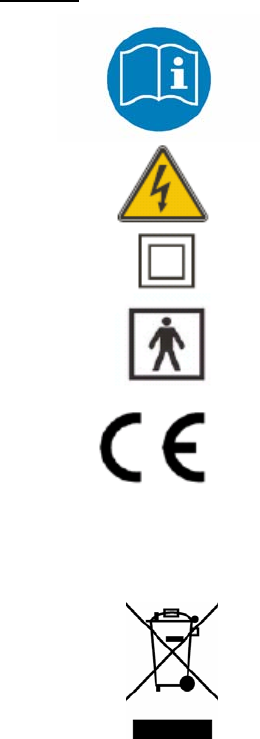
Symbols and Acronyms
Symbols
Attention/User Manual/device labeling
Warning: Shock Hazard
Class II, IEC 601-1
Type BF Applied Part
Mark identifying compliance with council directive 93/42/EEC
0123 is the identification mark of the Notified Body, TUV SÜD
responsible for evaluation of the CE Technical File.
0123
MN Abbreviation for model number
WEEE (Waste Electronic and Electrical Equipment) symbol
in accordance with council directive 2002/96/EC

DRAFT Page 30 of 32
Acronyms
ADC Analog to Digital Conversion
ASCEND The brand of the NeuroMetrix Nerve Localization Stimulator
BF Body Float (Type of medical device)
CRC Cyclic Redundancy Check
GUI Graphic User Interface
LCD Liquid Crystal Display
LED Light Emitting Diode
NC Nerve Stimulator
NNI Near Nerve Injection
RF Radio Frequency
UI User Interface

DRAFT Page 31 of 32
APPENDIX E
Accessories
Description Catalog Number
Charging Station AS-H01
Tab Electrode Cable AS-TEC
Electrode AS-001
Electrode Needle, Hypodermic, 20G, 150mm RA-20150
Electrode Needle, Hypodermic, 22G, 50mm RA-2250
Electrode Needle, Hypodermic, 22G, 75mm RA-2275
Electrode Needle, Hypodermic, 25G, 50mm RA-2550
Please contact NeuroMetrix customer service at 888-786-7287 to order accessories.

DRAFT Page 32 of 32
APPENDIX F
Electromagnetic Compatibility Declaration
ASCEND is intended for use in the electromagnetic environment specified below. The user should ensure that it is
used in such an environment.
Emissions test Compliance Electromagnetic environment – guidance
RF emissions
CISPR 11
Group 1
ASCEND uses RF energy for its function. Its RF emissions are
very low and are not likely to cause any interference in nearby
electronic equipment
RF emissions
CISPR 11
Class B
ASCEND is suitable for use in all establishments, including
domestic establishments and those directly connected to the public
low voltage power supply network that supplies buildings used for
domestic purposes.
Electrostatic Discharge
Immunity (ESD)
IEC 61000-4-2
±4kV contact
±8kV air
Floors should be wood, concrete or ceramic tile.
Radiated RF
IEC 61000-4-3
3 V/m
80 MHz to
2.7 GHz
3 V/m compliance level
Electrical fast
transient/burst
IEC 61000-4-4
±2kV power
supply lines
Input power quality should be that of a typical commercial or
hospital environment.
Surge
IEC 61000-4-5
±1kV
differential mode
±2kV common
mode
Input power quality should be that of a typical commercial or
hospital environment.
Conducted RF
IEC 61000-4-6
3 V RMS
150 kHz to
80 MHz
3 V/m compliance level
Power frequency (50/60
Hz) magnetic field
IEC 61000-4-8
3 A/m
3 A/m compliance level
Voltage dips, short
interruptions and voltage
variations on power
supply input lines
IEC 61000-4-11
>95% dip in UT for
0.5 cycle
60% dip in UT
for 5 cycles
30% dip in UT
for 25 cycles
>95% dip in UT
for 5 s
Input power quality should be that of a typical commercial or
hospital environment.
Harmonics and Flicker
EN61000-3-2
EN61000-3-3
Class A
N/A
Input power quality should be that of a typical commercial or
hospital environment.