NextNav 100-0013-01 Metropolitan Beacon System User Manual Operating manual
NextNav,LLC Metropolitan Beacon System Operating manual
NextNav >
Contents
- 1. Operating manual
- 2. User manual
Operating manual

Document Name: MBS Leopard Transmitter Usert NOC Operating Manual
Version No: 1.4
Company Name: NextNav, LLC.
Confidential Page 1 3/10/2014
Page 1 of 13
MBS Leopard Transmitter
User NOC Operating Manual
SYS-NN-SS-OG-1158.00-NextNav Leopard NOC User manual
Version 1.4
NextNav Confidential and Proprietary
Restricted Distribution. Not to be distributed to anyone who is not an employee of either NextNav or a
subsidiary of NextNav without the express approval of NextNav Document Control.
All data and information contained in or disclosed by this document is confidential and proprietary
information of NextNav, LLC and all rights therein are expressly reserved. By accepting this material, the
recipient agrees that this material and the information contained therein is to be held in confidence and in
trust and will not be disseminated, distributed, copied, reproduced in whole or in part, nor its contents
revealed in any manner to others without the express written permission of NextNav LLC.

Document Name: MBS Leopard Transmitter Usert NOC Operating Manual
Version No: 1.4
Company Name: NextNav, LLC.
Confidential Page 2 3/10/2014
Page 2 of 13
History
Version
Date
Author
Notes
1
Initial Draft Version
Arun Narayan
1,2
2
November 20, 2013
Waldemar Kunysz
3
3
February 26, 2014
Waldemar Kunysz
4
4
March 10, 2014
Waldemar Kunysz
5
Notes:
1. Initial Version
2. Document naming convention used.
3. Revised version
4. Revised ERP Table
5. Revised ERP Table for IDB mode to bring ERP levels to 30 Watts

Document Name: MBS Leopard Transmitter Usert NOC Operating Manual
Version No: 1.4
Company Name: NextNav, LLC.
Confidential Page 3 3/10/2014
Page 3 of 13
Table of Contents
History ........................................................................................................................................... 2
Notes:............................................................................................................................................. 2
1 Introduction ............................................................................................................................. 4
1.1 Purpose and Scope ...................................................................................................................................... 4
1.2 Intended Use ................................................................................................................................................. 4
1.3 FCC Compliance Statements ..................................................................................................................... 4
2 NextNav Leopard Beacon Commissioning ........................................................................... 5
2.1 Equipment List .............................................................................................................................................. 6
2.2 Confirm Front Panel Cable Connections .......................................................................................................... 7
2.3 Power-up Sequence ..................................................................................................................................... 8
2.4 TX Antenna .................................................................................................................................................. 11
2.5 GPS Receive Antenna ............................................................................................................................... 11
2.6 Tune-up procedure not to exceed maximum TX power ........................................................................ 12
3 Technical Specifications ..................................................................................................... 13
Table of Figures
Figure 1 Leopard Front Panels ................................................................................................... 7
Figure 2 AC Mains Connect ........................................................................................................ 8
Figure 3 Cabinet Power ............................................................................................................... 9
Figure 4 Load Breaker ............................................................................................................... 10
Figure 5 Battery Breaker Antenna Mounting .......................................................................... 11

Document Name: MBS Leopard Transmitter Usert NOC Operating Manual
Version No: 1.4
Company Name: NextNav, LLC.
Confidential Page 4 3/10/2014
Page 4 of 13
1 Introduction
The goal of the MBS system is to provide high precision, reliable, ubiquitous positioning system
providing GPS like accuracies in indoors and urban canyons where it is challenging to get any
reliable position using GPS or other wide area reliable technologies. In addition to improved 2-D
accuracy the MBS system also provides meter level accuracy in the vertical dimension with the
aid of a MEMS pressure sensor. MBS technology provides a very fast time to first fix (TTFF) in
the order of ~5 seconds under cold start conditions. Similar to GPS, MBS technology allows
computation of the location on the device without any network dependence thus enabling a
wide variety of standalone applications. The signal structure of MBS is designed so that the
signal processing entities of a standard GPS receiver’s baseband can be reused. The system is
fundamentally designed for low power consumption of the receivers.
1.1 Purpose and Scope
This document describes the commissioning and normal usage procedure for the
NextNav Local beacon box (A4P-100-0013-01).
1.2 Intended Use
The NextNav Leopard beacon system is intended to be used in restricted access locations (RAL)
in outdoor and indoor environments. The NextNav Leopard beacon is a powered by a AC
power system approved for use in telecommunications equipment.
1.3 FCC Compliance Statements
FCC Section 15.21 Information to user.
Any changes or modifications to the equipment operation settings must be approved by the
NextNav, LLC for FCC compliance; otherwise the user's authority to operate the equipment
will be voided.
Section 15.105(b) Class A digital device Information to the user
This equipment has been tested and found to comply with the limits for a Class A digital
device, pursuant to Part 15 of the FCC Rules. These limits are designed to provide reasonable
protection against harmful interference when the equipment is operated in a commercial
environment. This equipment generates, uses, and can radiate radio frequency energy and, if
not installed and used in accordance with the instruction manual, may cause harmful
Document Name: MBS Leopard Transmitter Usert NOC Operating Manual
Version No: 1.4
Company Name: NextNav, LLC.
Confidential Page 5 3/10/2014
Page 5 of 13
interference to radio communications. Operation of this equipment in a residential area is
likely to cause harmful interference in which case the user will be required to correct the
interference at his own expense.
RF Exposure Statement
This equipment complies with FCC radiation exposure limits set forth for an uncontrolled
environment. This equipment should be installed and operated with a minimum distance of 1m
between the antenna and any body part of the user or nearby persons.
2 NextNav Leopard Beacon Commissioning
Once the NextNav leopard Box is installed in the field and the installation checklist is
verified, a field technician follows the following sequence of operations to power up the
box as illustrated in Error! Reference source not found. and the following checklist can
be used for verification of completion of the steps needed.
Installation Tech checklist
1
GPS antenna connection
Yes No
2
Tx antenna connection
Yes No
3
EvDO antenna connection
Yes No
4
Ethernet router port activity
Yes No
5
Able to browse internet from field service laptop
using Ethernet port on MBS Leopard beacon box
Yes No
6
Enable port forwarding if not already done at
manufacturing site
Yes No
7
TX antenna LLA survey done
Yes No
8
Weather board LLA survey done
Yes No
9
GPS antenna LLA survey done
Yes No
10
Survey ground truth of the TX antenna, GPS
antenna and weatherboard
Yes No
Table 1 Commissioning Procedure Steps for Installation Technician

Document Name: MBS Leopard Transmitter Usert NOC Operating Manual
Version No: 1.4
Company Name: NextNav, LLC.
Confidential Page 6 3/10/2014
Page 6 of 13
2.1 Equipment List
• NextNav Leopard Beacon
• Approved Transmit Antenna (See section )
• GPS Antenna (PN: BL1R-A-XTB-1-FKM)
• EVDO Antenna (PN: PSKN-900/1900S)
• NextNav WeatherBoard unit
RF cables as per chart below:
Description
Cable Type
Cable Length (max)
GPS Cable
LMR400
150’
AL4RPV-50
250’
Tx Cable
LMR400
250’
AL4RPV-50
400’
Document Name: MBS Leopard Transmitter Usert NOC Operating Manual
Version No: 1.4
Company Name: NextNav, LLC.
Confidential Page 7 3/10/2014
Page 7 of 13
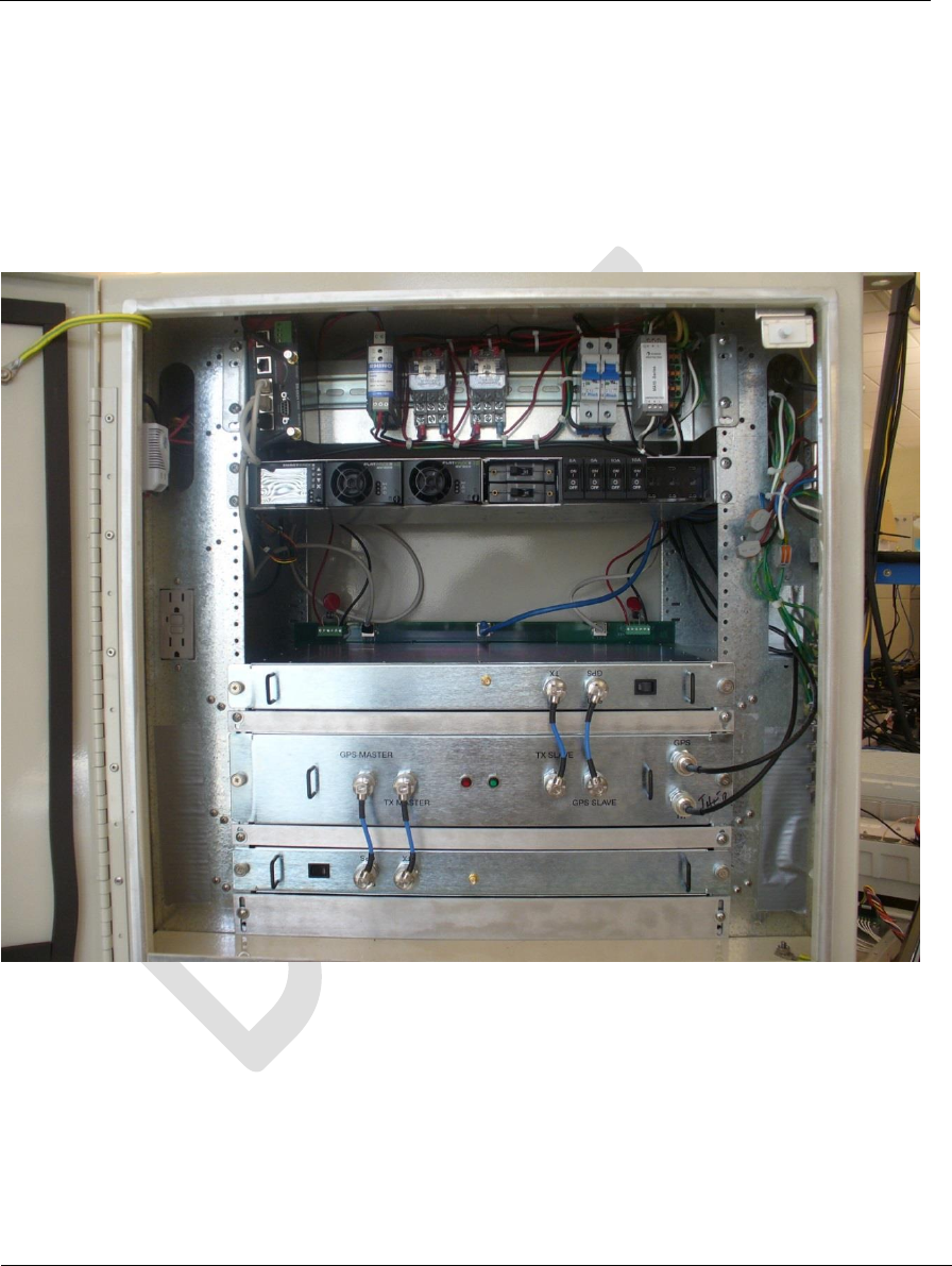
2.2 Confirm Front Panel Cable Connections
The slave unit (bottom module shown in Fig 1 and the master units are connected to the timing
tray using a backplane board (behind the units) and 4 coaxial cables in the front as shown. Make
sure that GPS antenna cable is connected to the top right hand side connector and TX antenna
to the bottom one.
Figure 1 Leopard Front Panels
1. Verify the following external connections to the beacon:
a) GPS antenna connection to the Leopard Box
b) Tx antenna cable connection to the ‘TX’ port.
c) Weather box connection to the WEATHER port.
d) EvDO antenna cables to the EvDO Tx port. In cases of sites which have
been documented as requiring EvDO diversity, connect the diversity
Document Name: MBS Leopard Transmitter Usert NOC Operating Manual
Version No: 1.4
Company Name: NextNav, LLC.
Confidential Page 8 3/10/2014
Page 8 of 13
antenna to the EvDO DIV port. In cases of sites which have been
documented as needing a POTS line, connect the phone line to the
‘TELCO’ port.
2. Verify that the following LEDs (located at the front panel) are lit indicating
proper operation:
a) Primary unit: Status indicator LED is lit in RED
3. Connect the field service laptop with an Ethernet cable to the ‘Ethernet’ port on
the MARS beacon box. Wait for a few seconds to get an IP address on the field
service laptop. Try and browse the internet to ensure connectivity. Once
connectivity is ensured, call the operator at the NOC to further commission the
beacon box.
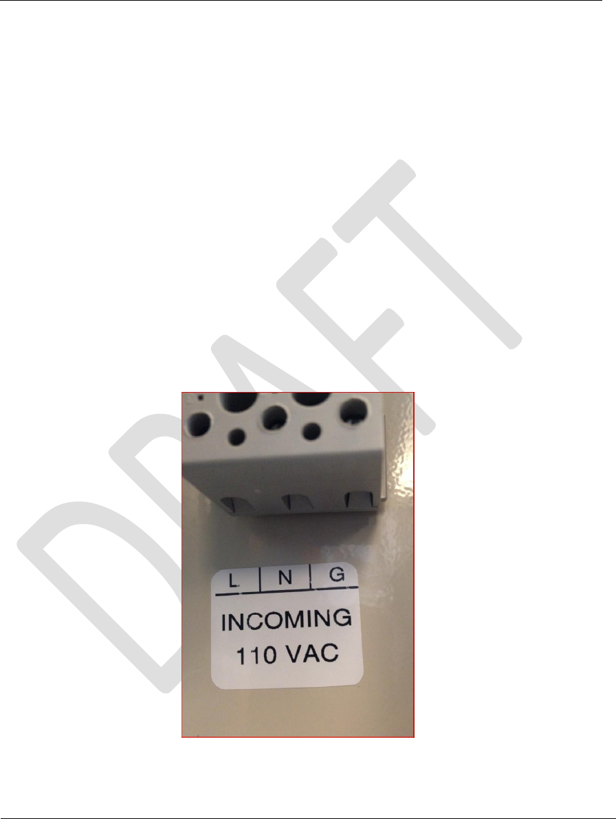
2.3 Power-up Sequence
Connect AC Lince Feed to terminal block labled Incoming AC.
Figure 2 AC Mains Connect
Document Name: MBS Leopard Transmitter Usert NOC Operating Manual
Version No: 1.4
Company Name: NextNav, LLC.
Confidential Page 9 3/10/2014
Page 9 of 13
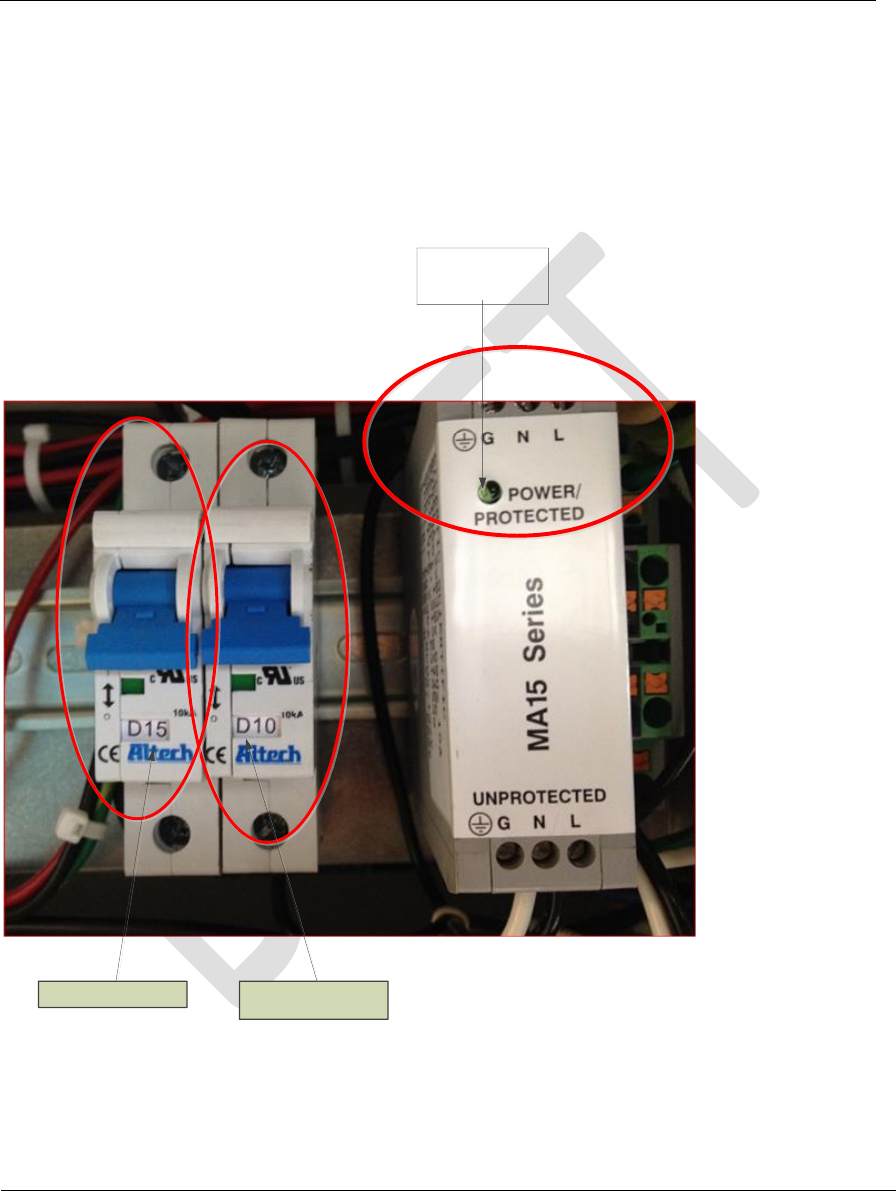
The Protected Power LED on the MA15 surge protector should turn on “GREEN LED” Indicates
AC power is on. This will only happen after the AC is connected and AC mains breaker turned
on.
Turn on Circuti Breaker D10 to power all NextNav equipemnt. At this time the Elteck Valare
Controller should turn on. Wait approximalty 1 minute before turnign on the load breakers.
AC Power ON
D15 : GFCI outlet D10 : NextNav
Equipment Power
Figure 3 Cabinet Power
The Protected Power LED on the MA15 surge protector should turn on “GREEN LED” Indicates
AC power is on. This will only happen after the AC is connected and AC mains breaker turned
on.
Document Name: MBS Leopard Transmitter Usert NOC Operating Manual
Version No: 1.4
Company Name: NextNav, LLC.
Confidential Page 10 3/10/2014
Page 10 of 13
Turn on Circuti Breaker D10 to power all NextNav equipemnt. At this time the Elteck Valare
Controller should turn on. Wait approximalty 1 minute before turnign on the load breakers.
Turn on D15 ; the circuit breaker to power the GFCI outlet in the cabinet and.
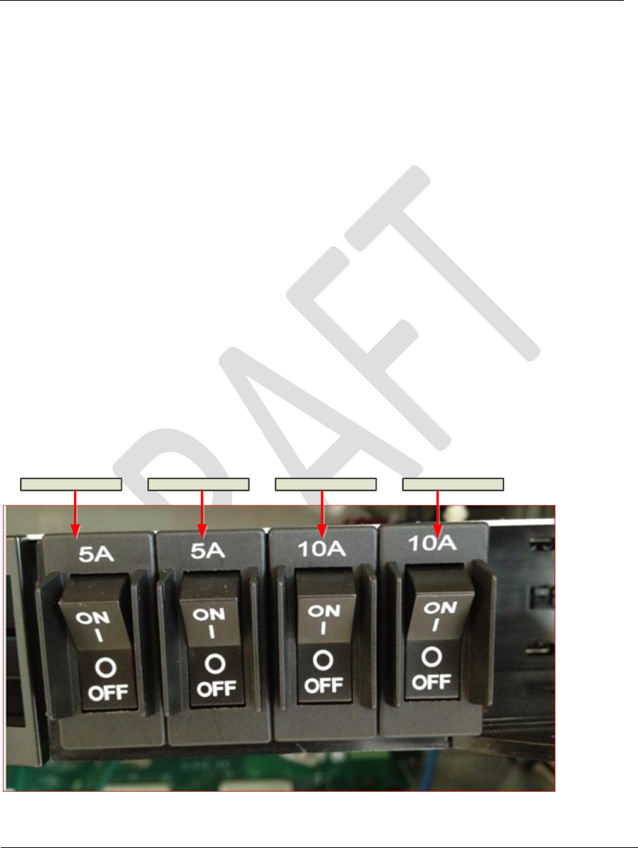
After waiting about a minute after turning on the D10 breaker, turn on the following breakers.
Heat Excahgner – 5 Amp load breaker; fan in the heat exchanger should start running.
Modem- 5 Amp load breaker; The swithc ports on the modem should start blinking.
Master Transmitter 10 Amp breaker; Turn on the 10 Amp load breaker labelled Master then
toggle the switch on the front panel of the Master Transmitter located on the bottom slot in the
rack to ON. The LED on the switch panel will light up to indicate that the Master Transmitter is
powered on. Also the GREEN LED on the Timign Tray ( Middle tray) will trun ON and stary on
after about 45 seconds.
Salve Transmitter 10 Amp Breaker; Turn on the 10 Amp load breaker labelled Slave then toggle
the switch on the front panel of the Salve ransmitter located on the bottom slot in the rack to
ON. The LED on the switch panel will light up to indicate that the Salve Transmitter is powered
on. Toggle power OFF on the Master transmitter tray and the LED on the Timing tray should
turn RED. After verifying this toggel the Master Transmitter to ON.
Heat Exchanger Modem Master Slave
Figure 4 Load Breaker
Document Name: MBS Leopard Transmitter Usert NOC Operating Manual
Version No: 1.4
Company Name: NextNav, LLC.
Confidential Page 11 3/10/2014
Page 11 of 13
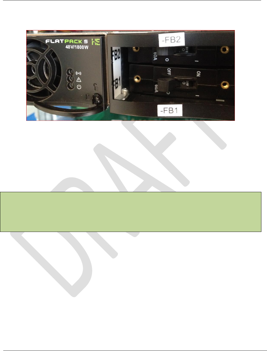
Turn on Battery Breakers FBI and FB2
Figure 5 Battery Breaker Antenna Mounting
2.4 TX Antenna
Tx antenna will be installed indoors. In normal configurations, antenna is to be attached to the
ceiling structures. Proper installation procedures must be followed as defined in site specific
construction drawing. As a general rule the TX antenna shall be kept a minimum distance of 6
feet from any metallic vertical structures on other types of obstructions.
This radio transmitter (FCC ID: A4P-100-0013-01) has been approved by FCC to operate with the
antenna types listed below with the maximum permissible gain and required antenna
impedance for each antenna type indicated. Antenna types not included in this list, having a gain
greater than the maximum gain indicated for that type, are strictly prohibited for use with this
device.
This radio transmitter may only operate using a vertically polarized antenna.
2.5 GPS Receive Antenna
GPS antenna should be installed such that it has clear view of sky. Ideally, you would keep the
antenna close to the ground away from obstruction
• Keep any horizontal blockage smaller than 10 degrees
• Obstruction Clearance guideline
– If it is 1 ft wide it should be at least 6 ft away
– If it is 10 ft wide, it should be at least 60 ft. away.
– If it is significantly less than 1 ft wide (like a guy wire, or a post) it should not cause any
measurable effect

Document Name: MBS Leopard Transmitter Usert NOC Operating Manual
Version No: 1.4
Company Name: NextNav, LLC.
Confidential Page 12 3/10/2014
Page 12 of 13
2.6 Tune-up procedure not to exceed maximum TX power
A CSV file (configuration file) per transmitter are created by the NOC engineer based on the
installation parameters such as line lengths, antenna type etc. The TX output power level
setting is contained in the CSV file.
The output power is adjusted by the ‘PA gain” setting. This value in the CSV file is calculated by
a formula to set the output power (not to exceed 30W ERP). The variables used in the
calculation include PA Gain (Gpa), TX Antenna Gain (Gant), TX filter insertion loss (ILflt), internal
cable loss (ILint), external cable loss (ILext), and transceiver output power (PTCVR).
ERP (W) = 10^((PTCVR - ILint + Gpa - ILflt - ILext + Gant) / 10) / 1000
The PA gain setting should be set to a proper value so that total sum of net antenna gain and
cable loss coupled with PA output does not exceed 30 Watts EIRP, PEP (Peak Envelope Power) .
Table 2 is a list of all possible antennas and RF cable combinations with corresponding RF power
settings required to comply with the FCC requirement of 30 Watts EIRP Peal Envelope Power
(PEP).
Tx Band
PA Gain
(dB)
PA out
(dBm)
Antenna
Type
Antenna
Gain
(dBd)
Cable
Loss (dB)
ERP
(dBm)
ERP (W)
(PEP)
2 MHz
60.3 max
+41.53
DB586-Y
6.0
2.8 min
+44.73
29.7
61.0 max
+42.23
SC433-
HF6LDF
2.5
0.0 min
+44.73
29.7
60.3 max
+41.53
BCD-8707
6.5
3.3 min
+44.73
29.7
60.6 max
+41.83
OD9-5
2.9
0.0 min
+44.73
29.7
IDB Mode A or B
2 MHz channel
59.0 max
+41.56
DB586-Y
6.0
2.8 min
+44.76
29.9
SC433-
HF6LDF
2.5
0.0 min
+44.06
25.5
BCD-8707
6.5
3.3 min
+44.76
29.9
OD9-5
2.9
0.0 min
+44.46
27.9
IDB Mode A or B
5 MHz channel
59.0 max
+41.33
DB586-Y
6.0
2.8 min
+44.53
28.4
SC433-
HF6LDF
2.5
0.0 min
+43.83
24.2
BCD-8707
6.5
3.3 min
+44.53
27.9
OD9-5
2.9
0.0 min
+44.23
26.5
Table 2 Maximum allowable RF power settings with various antenna/cable
Note 1: PA module provides means of RF Gain control in steps of 0.1 dB from 0 to 65 dB.
Maximum PA Gain values listed in the table2 are required to ensure that conducted and
radiated spurious emission standards of Part 90 are met . The difference of PA output

Document Name: MBS Leopard Transmitter Usert NOC Operating Manual
Version No: 1.4
Company Name: NextNav, LLC.
Confidential Page 13 3/10/2014
Page 13 of 13
levels between 2 MHz and IDB mode is compensated using internal RF attenuation that
can be set remotely by NOSS engineers to ensure that 30 Watts ERP is met in both
cases.
3 Technical Specifications
Parameter
Value/Description
Modulation
BPSK modulation with CDMA spreading
Maximum ON time
200ms/1second
Duration of a single burst
100ms
Center Frequencies
926.227MHz for single 2 MHz band and in IDB
band Type B
920.773 MHz for 2 MHz IDB band Type A
924.692 MHz for 5MHz in IDB band Type A
and B
Necessary Signal Bandwidth
2.046MHz for single band,
5.115MHz for IDB band Type A & B
Frequency Stability
<10ppb
EIRP
30W ERP `
Data Rate
99 bits in a 100ms slot
Power Supply
Nominal: 110 VAC (primary means)
48 VDC (secondary means – battery backup)
Power Consumption
330 W max, 140 W average, 7.5A
Operating Conditions
-40°C to +50°C, plus solar radiation
0 to 95% humidity, non-condensing
Remote Monitoring
Via SNMP protocol
Environmental Standard
IP66