Nokia Networks R242-V01 Rooftop Spread Spectrum Wireless Router User Manual
Nokia Networks Inc Rooftop Spread Spectrum Wireless Router
Contents
- 1. Revised Installation
- 2. Revised Users
Revised Installation

GSDU 468845A (paper)
WREM 070700A (on CD 468846A)
August, 2000
Nokia RoofTop™ Wireless Routing
Installation Guide

COPYRIGHT
© 2000 Nokia Corporation. All rights reserved.
Rights reserved under the copyright laws of the United States.
RESTRICTED RIGHTS LEGEND
Use, duplication, or disclosure by the Government is subject to restrictions as set forth in subparagraph (c)(1)(ii) of the Rights in
Technical Data and Computer Software clause at DFARS 252.227-7013.
IMPORTANT NOTE TO USERS
This device has been certified by the FCC as a Class B device and as such must be installed and/or moved by a profes-
sional.
TRADEMARKS
Nokia is a registered trademark of Nokia Corporation. Nokia RoofTop™ is a registered trademark of Nokia Networks.
Other products mentioned in this document are trademarks or registered trademarks of their respective holders.
COMPLIANCE STATEMENTS
This hardware complies with the standards listed in this section.
Emission Standards
UNINTENTIONAL EMISSIONS: FCC Part 15 CLASS B
INTENTIONAL EMISSIONS: FCC Part 15, Section 15.247
This equipment has been tested and found to comply with the limits for a Class B digital device, pursuant to Part 15 of the FCC
rules. These limits are designed to provide reasonable protection against harmful interference in a residential installation. This
equipment generates, uses, and can radiate radio frequency energy and, if not installed and used in accordance with the instruc-
tions, may cause harmful interference to radio communications. However, there is no guarantee that interference will not occur
in a particular installation. If this equipment does cause harmful interference to radio or television reception which can be deter-
mined by turning the equipment off and on, the user is encouraged to try and correct the interference by one or more of the fol-
lowing measures:
—Reorient or locate the receiving antenna.
—Increase the separation between the equipment and receiver.
—Connect the equipment into an outlet on a circuit different from that to which the receiver is connected.
—Consult the dealer or an experienced radio/TV technician for help.
Any modifications made to the unit, unless expressly approved by Nokia could void the user’s authority to operate the equip-
ment.
DISCLAIMER:
TO THE INSTALLER: THE INSTRUCTIONS PROVIDED IN THIS GUIDE ARE PROVIDED “AS IS” WITHOUT WARRANTY OF
ANY KIND EXPRESS OR IMPLIED. NOKIA MAKES NO REPRESENTATIONS OR WARRANTIES, EXPRESS OR IMPLIED,
INCLUDING BUT NOT LIMITED TO THE WARRANTIES OF MERCHANTABILITY OR FITNESS FOR A PARTICULAR PUR-
POSE OR INFRINGEMENT, INCLUDING ANY THIRD PARTY PATENTS, COPYRIGHTS, TRADEMARKS OR OTHER
RIGHTS. THERE IS NO WARRANTY BY NOKIA THAT THE INSTRUCTIONS CONTAINED IN THE GUIDE WILL MEET YOUR
REQUIREMENTS. THERE IS NO WARRANTY BY NOKIA THAT THE INSTRUCTIONS AND STATEMENTS CONTAINED IN

THE GUIDE OR ITS CONTENT ARE TRUE, ACCURATE OR COMPLETE.
LIMITATION OF LIABILITY: TO THE MAXIMUM EXTENT PERMITTED BY APPLICABLE LAW, IN NO EVENT SHALL NOKIA,
ITS EMPLOYEES OR AFFILIATES BE LIABLE FOR ANY LOST PROFITS, REVENUE, SALES, DATA, OR COSTS OF PRO-
CUREMENT OF SUBSTITUTE GOODS OR SERVICES, PROPERTY DAMAGE, PERSONAL INJURY, INTERRUPTION OF
BUSINESS, LOSS OF BUSINESS INFORMATION OR FOR ANY SPECIAL, DIRECT, INDIRECT, INCIDENTAL, ECONOMIC,
COVER, PUNITIVE, SPECIAL OR CONSEQUENTIAL DAMAGES HOWEVER CAUSED, AND WHETHER ARISING UNDER
CONTRACT, TORT, NEGLIGENCE, OR OTHER THEORY OF LIABILITY ARISING OUT OF THE USE OF OR INABILITY TO
USE THE GUIDE, EVEN IF NOKIA OR AFFILIATES ARE ADVISED OF THE POSSIBILITY OF SUCH DAMAGES.
SAFETY WARNING:
THE ANTENNA FOR THIS TRANSMITTER MUST BE INSTALLED TO PROVIDE A SEPARATION
DISTANCE OF 2 METERS OR MORE FROM PERSONS TO ENSURE COMPLIANCE WITH EXPOSURE
GUIDELINES. THE ANTENNAS USED FOR THIS TRANSMITTER MAY NOT BE CO-LOCATED OR
OPERATED IN CONJUNCTION WITH ANY OTHER ANTENNA OR TRANSMITTER.


Nokia RoofTop™ Wireless Routing Installation Guide v
Contents
CHAPTER 1 System Overview . . . . . . . . . . . . . . . . . . . . . . . . . . . . . . .1
1.1 Introduction . . . . . . . . . . . . . . . . . . . . . . . . . . . . .1
CHAPTER 2 Antenna Installation . . . . . . . . . . . . . . . . . . . . . . . . . . . 5
2.1 Introduction . . . . . . . . . . . . . . . . . . . . . . . . . . . . .5
2.2 Site Analysis . . . . . . . . . . . . . . . . . . . . . . . . . . . .6
2.2.1 RF Link Feasibility. . . . . . . . . . . . . . . . . . . . . . . . 6
2.3 Line of Sight Analysis . . . . . . . . . . . . . . . . . . . . . 8
2.3.1 Visual Line of Sight . . . . . . . . . . . . . . . . . . . . . . . 8
2.3.2 Radio Line of Sight . . . . . . . . . . . . . . . . . . . . . . . 9
2.3.3 Fresnel Zone. . . . . . . . . . . . . . . . . . . . . . . . . . . . . 9
2.3.4 Antenna Height. . . . . . . . . . . . . . . . . . . . . . . . . . . 9
2.4 Antenna Selection . . . . . . . . . . . . . . . . . . . . . . . 10
2.4.1 Omnidirectional Antennas . . . . . . . . . . . . . . . . . 10
2.4.2 Directional Antennas . . . . . . . . . . . . . . . . . . . . . 10
2.5 Cables . . . . . . . . . . . . . . . . . . . . . . . . . . . . . . . . 12
2.6 Outdoor Installation Procedures . . . . . . . . . . . . 13
2.6.1 Safety Guidelines . . . . . . . . . . . . . . . . . . . . . . . . 13
2.6.2 Required Installation Components. . . . . . . . . . . 13
2.6.3 Polarization. . . . . . . . . . . . . . . . . . . . . . . . . . . . . 14
2.6.4 Test Installation . . . . . . . . . . . . . . . . . . . . . . . . . 14
2.6.5 Grounding. . . . . . . . . . . . . . . . . . . . . . . . . . . . . . 15
2.6.6 Weatherproofing. . . . . . . . . . . . . . . . . . . . . . . . . 16
2.6.7 Weatherproofing Flexible RF Jumper Cables . . 19
2.6.8 Amplifier Weatherproofing . . . . . . . . . . . . . . . . 20
2.7 Indoor Installation Procedures. . . . . . . . . . . . . . 21
2.7.1 Weatherproofing. . . . . . . . . . . . . . . . . . . . . . . . . 21
2.7.2 Antennas. . . . . . . . . . . . . . . . . . . . . . . . . . . . . . . 21
2.7.3 Grounding. . . . . . . . . . . . . . . . . . . . . . . . . . . . . . 21
CHAPTER 3 Wireless Router Installation . . . . . . . . . . . . . . . . . . 23
3.1 Introduction . . . . . . . . . . . . . . . . . . . . . . . . . . . . 23
3.1.1 Preinstallation Requirements . . . . . . . . . . . . . . . 23

vi Nokia RoofTop™ Wireless Routing Installation Guide
Contents
3.1.2 Physical Location . . . . . . . . . . . . . . . . . . . . . . . . 24
3.1.3 Physical Mounting . . . . . . . . . . . . . . . . . . . . . . . 24
3.1.4 Connection Options . . . . . . . . . . . . . . . . . . . . . . 25
3.1.5 Amplifiers. . . . . . . . . . . . . . . . . . . . . . . . . . . . . . 26
3.2 Front Panel . . . . . . . . . . . . . . . . . . . . . . . . . . . . 28
3.2.1 LED Indicators . . . . . . . . . . . . . . . . . . . . . . . . . . 28
3.2.2 Configuration . . . . . . . . . . . . . . . . . . . . . . . . . . . 29
3.3 Rear Panel. . . . . . . . . . . . . . . . . . . . . . . . . . . . . 30
APPENDIX A Cables . . . . . . . . . . . . . . . . . . . . . . . . . . . . . . . . . . . . . . . . . 31
APPENDIX B Network Planning Guidelines . . . . . . . . . . . . . . . . 33
APPENDIX C Technical Specifications . . . . . . . . . . . . . . . . . . . . . 35

Nokia RoofTop™ Wireless Routing Installation Guide 1
CHAPTER 1 System Overview
1.1 Introduction
This chapter provides:
•A basic understanding of how a wireless router system functions
•How wireless systems self-configure
Wireless router networks bypass the wired local loop with fast “always-
on” wireless Internet access.
The Nokia AIR™ Operating System (OS) provides intelligence, security
and ease of use to make wireless networks practical, simple to deploy, and
cost effective. Wireless Internet or intranet access across a network is
completely transparent to the end user.
The Nokia RoofTop™ Wireless Routers, Models R242/242A, are both
wireless Internet access devices and IP routers. The wireless router units
operate in a mesh network where line of sight access is required to only
one other wireless router.

2 Nokia RoofTop™ Wireless Routing Installation Guide
1.1.1 Configuration
When the units are configured and deployed, they adapt to the network
automatically to learn the network topology. The operating system then
builds and maintains the network topology and routing tables, and
continually updates them as the network changes.
Line of sight problems, common in point-to-multipoint networks, are
eliminated by routing traffic through other units. If a node cannot connect
directly to the AirHead, multihop routing protocols forward traffic
through another wireless router.
Operating system protocols optimize wireless links providing hop-by-hop
data integrity and efficient, intelligent multicasting. Protocols control
channel scheduling, neighbor authentication, and link maintenance, as
well as optimize routing in the wireless environment. By scheduling
traffic streams to non-conflicting transmission times and Radio
Frequency (RF) channels, quality-sensitive and/or bandwidth intensive
applications co-exist with standard applications.
1.1.2 Installation Components
Each installation consists of a Nokia RoofTop™ Wireless Router, RF
cabling, lightning protection, and an amplifier (optional). The antennas
mount on the roof, or in a location in line of sight to other antennas in the
network. RF cabling is run from the antenna to the wireless router, which
is mounted indoors.
A successful installation requires:
•Site analysis and proper planning (section 2.3)
•Placement of the antenna with line of sight to at least one antenna
in the network (section 2.3)
•Using appropriate antenna and cabling (Sections 2.4 and 2.5)
•Proper installation technique, including grounding and
weatherproofing (Section 2.6)

Nokia RoofTop™ Wireless Routing Installation Guide 3
Introduction
•Proper placement and mounting of the wireless router (Section
3.1)
•Proper use of cabling between the wireless router and the
subscribers’ PC/network (Section 3.1.7)

4 Nokia RoofTop™ Wireless Routing Installation Guide

Nokia RoofTop™ Wireless Routing Installation Guide 5
CHAPTER 2 Antenna Installation
2.1 Introduction
Chapter topics include:
•Site Analysis
•Line of Sight Analysis
•Antenna Selection
•Cables
•Outdoor Installation Procedures
•Safety Guidelines
•Required Installation Components
•Polarization
•Test Installation
•Grounding
•Weatherproofing
•Indoor Installation Procedures

6 Nokia RoofTop™ Wireless Routing Installation Guide
2.2 Site Analysis
The goals of site analysis are:
•To determine the feasibility of RF links at each site
•To determine the antenna and cable requirements necessary to
provide service
2.2.1 RF Link Feasibility
Wireless routers operate in a “mesh” network—line of sight is required to
only one other radio in the network. The IP routing capability allows all
units to act as repeaters for other units.
Survey all obstructions to potential sites. For most installations use an
omnidirectional antenna. This assures maximum connectivity and allows
the unit to forward packets for existing and future needs.
NOTE: To maintain broadband data rates, it is recommended that
networks be kept within three hops.
2.2.1.1 Site Survey Steps
1. Determine if there are Line of Sight (LOS) paths for each proposed
link. Line of sight exists if there are no obstructions (for example,
trees, buildings, etc.) between the antennas. For best results, there
should be no obstructions between the two antennas. For long
distance paths there should be no obstacles close to the RF path.
2. Determine the antenna location and maximum possible antenna
height. The height of the antenna is often dependent on the physical
limitations of the site. For example, an antenna mast can be placed on
a rooftop, an antenna can be installed on an existing structure or
tower, or the mast and antenna can be installed on the ground.

Nokia RoofTop™ Wireless Routing Installation Guide 7
Site Analysis
3. Determine the RF paths between the antenna at the site and the
antennas at adjacent sites. For a directional link with a single antenna,
there is only one RF path. For an omnidirectional antenna, determine
all RF paths. The RF path can be determined by knowing the relative
bearing from the current site to adjacent sites.
4. The feasibility of an RF link can be estimated based on:
•Distances between the potential sites
•The line of sight for the RF paths
•Antenna RF gains
•Cable losses
5. After one or more sites have been installed and are operational, test
each new site before completing the installation.
6. After determining the feasibility of the RF link, consider the
following:
•Hardware and tools necessary to complete the installation
•Wireless router installation location
•The RF cable routing between the wireless router and the antenna
•Power for the wireless router
•Ethernet cable routing
•Antenna grounding and lightning arrestor requirements
8 Nokia RoofTop™ Wireless Routing Installation Guide
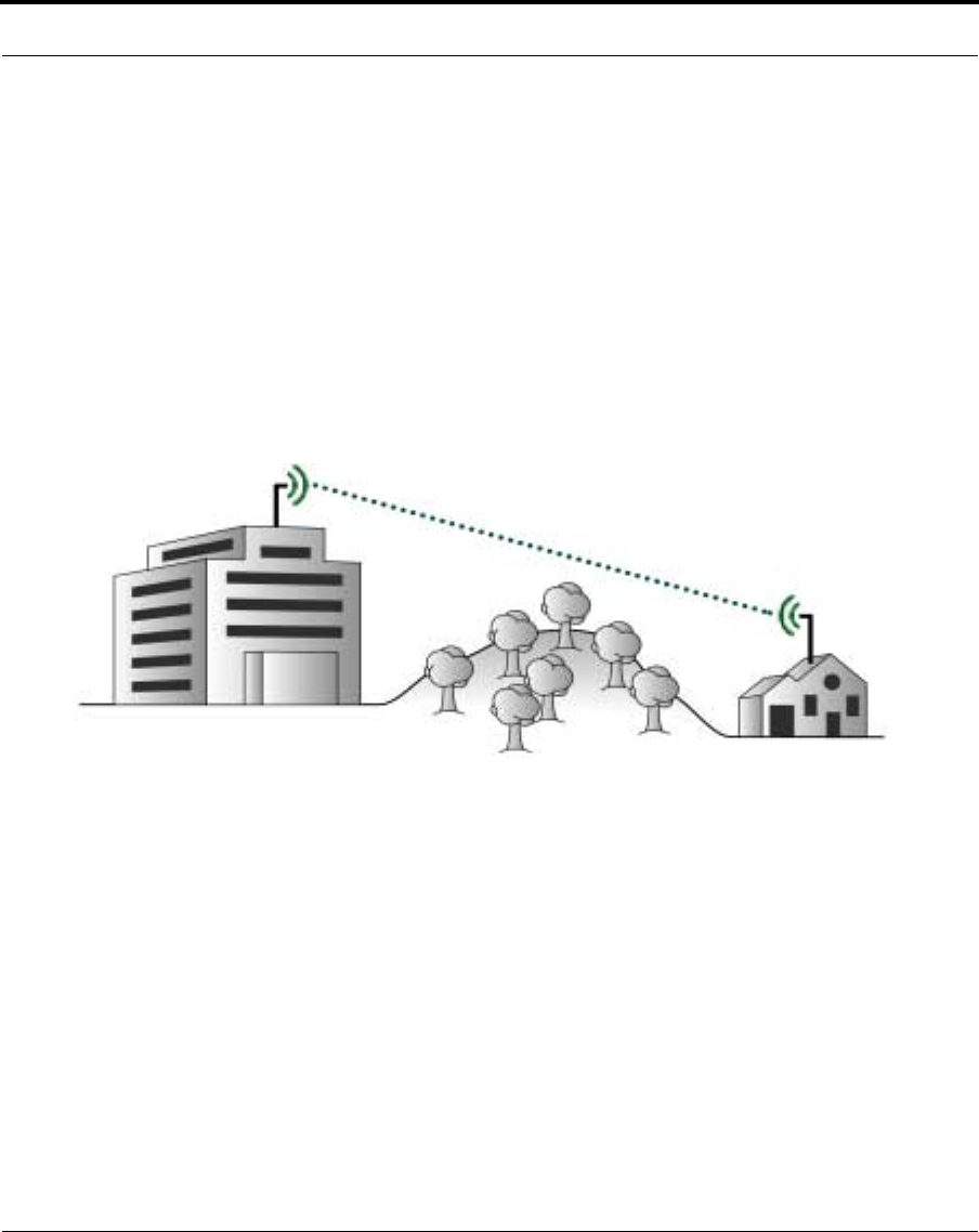
2.3 Line of Sight Analysis
A quality antenna installation includes:
•Clear visual line of sight between antennas
•Clear radio line of sight between antennas
•Antenna and cable selection and mounting based on the site
requirements and limitations
2.3.1 Visual Line of Sight
Visual line of sight exists when an imaginary straight line can be drawn
between two antennas without passing through any physical obstructions.
Verifying visual line of sight is the first step in planning. Observation
points must be high enough to allow the viewer to see over obstructions.
Nokia RoofTop™ Wireless Routing Installation Guide 9
Line of Sight Analysis
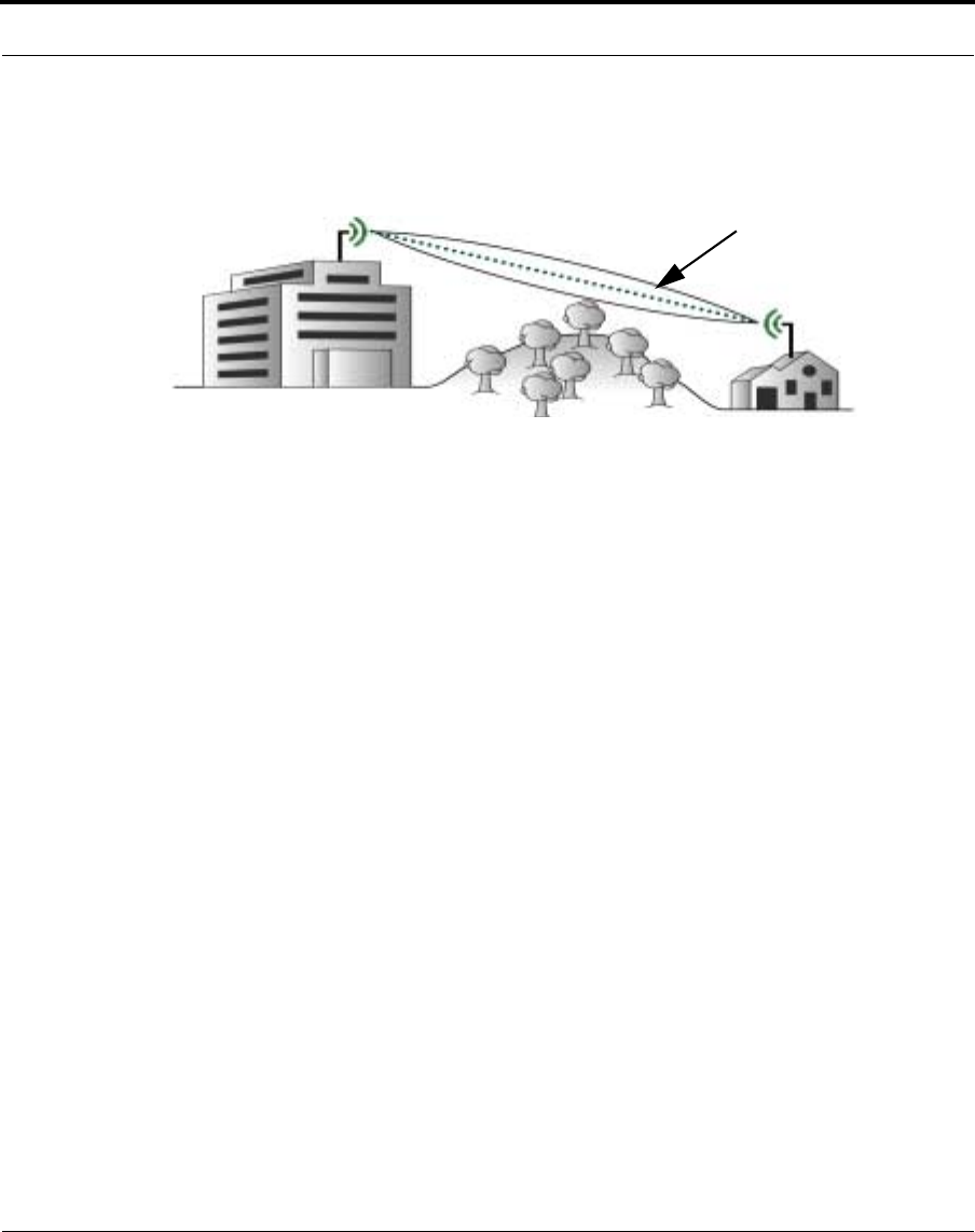
2.3.2 Radio Line of Sight
Provide a clear radio path by raising the antenna as high as possible and
away from objects near the radio path. A radio wave is not like a laser
with a narrow, pointed beam. RF waves fan out from a single source and
are diffracted or absorbed by objects that are near the visual line of sight.
This area is called the Fresnel Zone. Clear radio line of sight exists when
there are no physical obstructions in the Fresnel Zone.
2.3.3 Fresnel Zone
Elevate antennas as high as practical above physical obstacles to avoid
obstructing the Fresnel Zone, the elliptical area adjacent to the path, that
could reflect unwanted signals into the primary path and reduce signal
levels. The Fresnel Zone must be considered when installing antennas.
2.3.4 Antenna Height
All antennas have a limited vertical radiation pattern. If nearby antennas
are placed at different heights, verify that the vertical line of sight angle
falls within the antenna specifications for a good link.
Fresnel Zone
10 Nokia RoofTop™ Wireless Routing Installation Guide
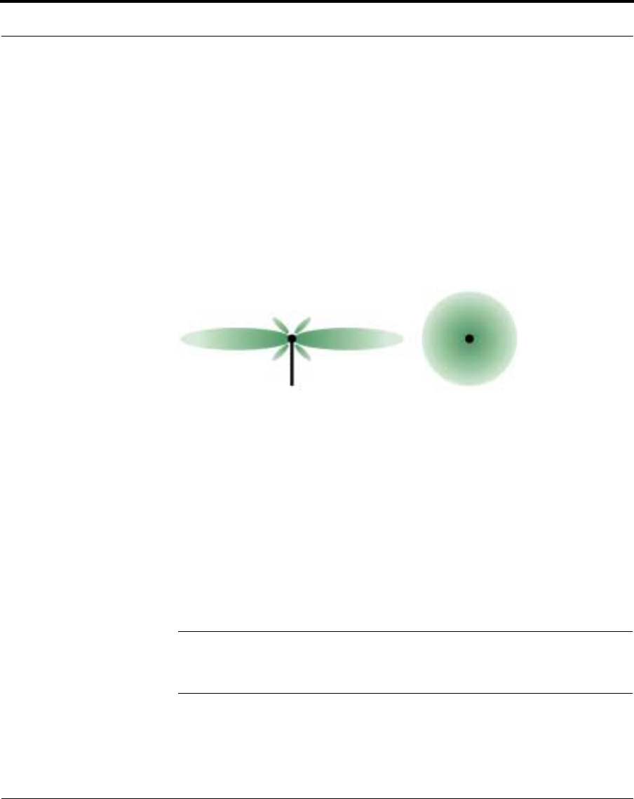
2.4 Antenna Selection
2.4.1 Omnidirectional Antennas
Omnidirectional antennas radiate spherically, providing equal coverage in
all directions, and are best for multi-point links and forwarding sites.
Because they receive and transmit signals in all directions, they are the
best antenna for most installations.
Omnidirectional Antennas - Radiation Pattern
2.4.2 Directional Antennas
Directional antennas focus their RF beam in narrow patterns in one
direction. Directional antennas provide communications over longer
ranges than omnidirectional antennas, but are much more limited in the
areas they cover. Directional antennas maximize link distances. They are
also effective for simple, dedicated, point-to-point links.
NOTE: Directional antennas limit future growth and prevent the wireless
modem from repeating signals to other units. They should be used only
where an omnidirectional antenna will not work.
Side View Top View

Nokia RoofTop™ Wireless Routing Installation Guide 11
Antenna Selection
Directional Antennas - Radiation Pattern Side View

12 Nokia RoofTop™ Wireless Routing Installation Guide
2.5 Cables
Nokia provides two types of RF cabling for wireless router installations:
1. Low Loss RF Cable - rigid low attenuation cable for long cable runs.
2. Flexible Jumper Cables - flexible cables, up to six feet long, that
connect the wireless router to the low loss RF cable or connect
amplifier components with the wireless router and antenna.
NOTE: Only use the RF cables provided by Nokia. Using cables or RF
equipment other than that provided by Nokia may void the user’s
authority to operate the equipment.

Nokia RoofTop™ Wireless Routing Installation Guide 13
Outdoor Installation Procedures
2.6 Outdoor Installation Procedures
WARNING: Use extreme caution when installing antennas in areas
with overhead power lines. Outdoor antennas and their supporting
masts, guy wires, and cables are electrical conductors. Contact with
high-voltage electrical wires can cause serious injury or death.
2.6.1 Safety Guidelines
•Plan the entire procedure before starting
•If necessary, obtain appropriate assistance
•Wear a hard hat and gloves
•Wear heavy toe boots to protect your feet from falling objects
•Do not install antennas on windy or rainy days
•Assemble the antenna components at or near the final site
•Ground the antenna support structure prior to erecting the antenna
•Firmly anchor the base of the support structure
•Keep the antenna at least twice the mast height from power lines
•If you start to drop an antenna, let it fall and back away from it
•Installations must be performed by a professional
•Maintain at least six feet (two meters) distance from the antenna
while the wireless router is on
•Install antennas at least six feet (two meters) above ground
2.6.2 Required Installation Components
•RF cabling
•Lightning protector
•Antenna
•Antenna mounting hardware

14 Nokia RoofTop™ Wireless Routing Installation Guide
•Antenna mast and hardware
2.6.3 Polarization
Polarization refers to the direction of antenna element alignment. For
antennas to properly communicate with each other, all antenna must be
aligned (polarized) in the same direction.
2.6.3.1 Omnidirectional Antenna
This vertically polarized antenna can only be mounted vertically.
2.6.3.2 Directional Panel Antenna
•Polarization is identified by an arrow on the rear panel
•Radiates from the front side and away from the mounting bracket
•Can be vertically or horizontally polarized; the elements can be
vertical or horizontal
NOTE: If you have a combination of vertical omnidirectional antennas
and directional antennas, the directional antennas must be polarized
vertically.
2.6.4 Test Installation
Connect and test all of the equipment prior to completing the permanent
installation. After confirming operation, disassemble only as much of the
equipment as is necessary to permanently reinstall it.
Nokia RoofTop™ Wireless Routing Installation Guide 15
Outdoor Installation Procedures
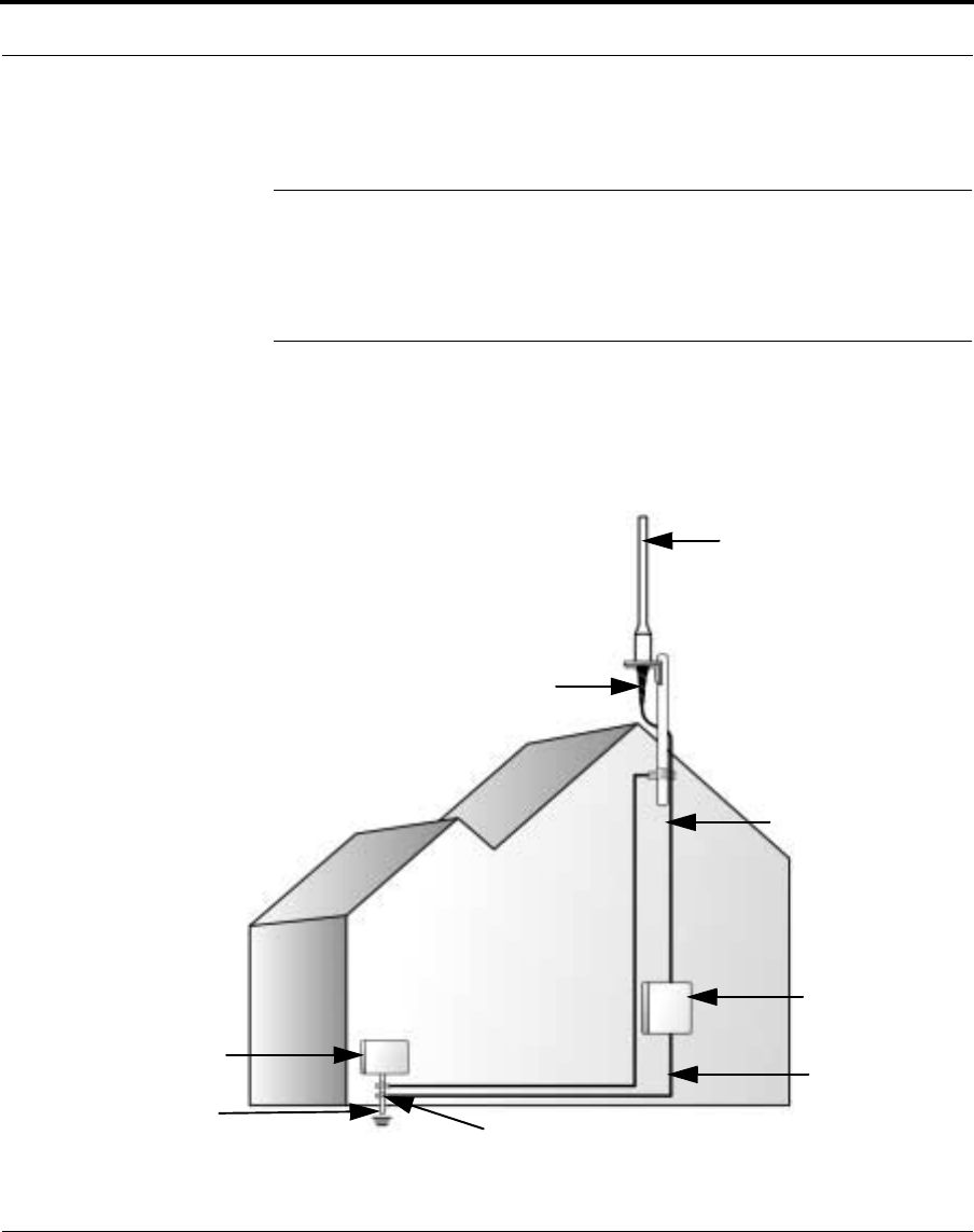
2.6.5 Grounding
WARNING: Because antennas are elevated metal objects with
connections to ground, they attract lightning. Attach an effective
ground to the antennas to provide a path for the lightning. Effective
antenna grounding also minimizes electrical noise and interference,
which can degrade system performance.
1. Provide a good, very low resistance wire connection from the antenna
mount and wireless router to earth ground.
2. Use #12 copper or aluminum wire connected to the metal antenna
support and a ground rod next to the building.
Grounding diagram
Antenna
Antenna Lead-in Wire
Lightning Arrestor
Electrical Service Equipment
Ground Rod
Weatherproof Connection
Grounding Conductors
#12 Copper or Aluminum
Ground Clamps

16 Nokia RoofTop™ Wireless Routing Installation Guide
3. Mount the antenna on a mast or tower that is well grounded to earth.
4. Weatherproof all ground connectors to prevent corrosion, which
interferes with the grounding connection.
5. Connect all power and antenna grounds to a common single point
such as an equipment rack, cabinet enclosure chassis, or antenna
tower. Connect this single-point ground to a solid ground connection
to earth.
6. Install a lightning arrestor where the antenna cable enters the building
or cabinet. Ground the lightning arrestor to a single point chassis
ground. Follow the instructions provided by the manufacturer.
2.6.6 Weatherproofing
Good weatherproofing is the key to antennas that work well in all weather
conditions. If water or moisture enters a cable or connector, it
significantly reduces signal levels and often ruins the cable and/or
connectors.
All connections that may be exposed to outdoor weather conditions or
moisture, including condensation must be weatherproofed.
NOTE: Whenever possible, connect and weatherproof the cables,
antennas, and any accessories on the ground. Minimize the amount of
work performed on a roof or a ladder.
2.6.6.1 Weatherproofing Supplies
•Self-vulcanizing weatherproofing tape (available from Nokia)
•Scissors
2.6.6.2 Weatherproofing Steps
For all outdoor connections, use the following procedures to
weatherproof the connections.
Nokia RoofTop™ Wireless Routing Installation Guide 17
Outdoor Installation Procedures
1. Connect the antenna and RF cable. Only connect cables at this step,
attaching other mounting hardware will make applying the
weatherproofing tape more difficult. See the NOTE for an exception.
NOTE: When using a flat rectangular antenna mounting bracket you must
attach the antenna to the mounting bracket before weatherproofing, or
you will be unable to attach the antenna to the mount, because the
weatherproofing will prevent the antenna from passing through the
antenna mounting hole.
Mounting Bracket
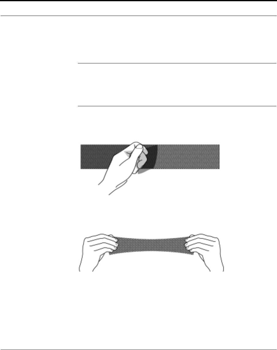
2. Cut an 8-inch section of the weatherproofing tape and remove the
black plastic film from the back of the tape.
3. Stretch and apply the tape to the connection, wrapping the tape in the
direction of the connector threading. Pull the tape tight while
wrapping.
18 Nokia RoofTop™ Wireless Routing Installation Guide
4. Apply the tape so that it covers the bottom of the antenna and the top
of the connector without gaps. To be certain that there are no gaps
apply the tape so that it overlaps half the width of the tape on each
wrap. (The gaps can allow water to enter the connector and cable).
5. Continue applying the tape to at least 2” below the connector.
6. Squeeze the tape against the antenna and connector to remove any air
gaps.
7. Attach the antenna to the mast or other mounting solution.
8. Attach the antenna to the mast or other structural support
Nokia RoofTop™ Wireless Routing Installation Guide 19
Outdoor Installation Procedures
NOTE: Be careful when weatherproofing RF connectors. Do not stress or
bend the cable during the process.
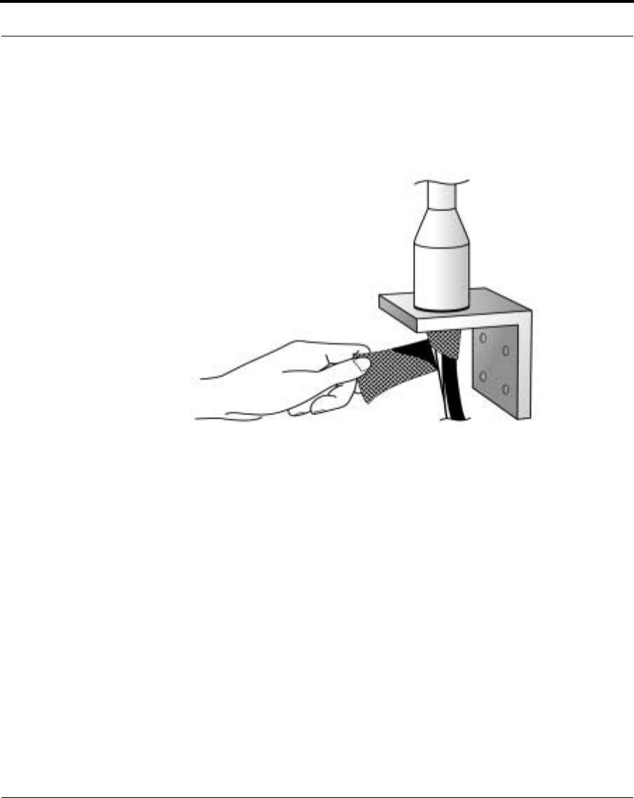
2.6.7 Weatherproofing Flexible RF Jumper Cables
When using flexible RF jumpers in the installation, weatherproof all
connectors and connections that are exposed or could potentially be
exposed to outdoor conditions (including condensation). Use the same
technique described for weatherproofing antenna connections. Extend the
weatherproofing tape at least two inches beyond each connection on the
cable.
Properly weatherproofed antenna connection.
Antenna mounting brackets may vary.

20 Nokia RoofTop™ Wireless Routing Installation Guide
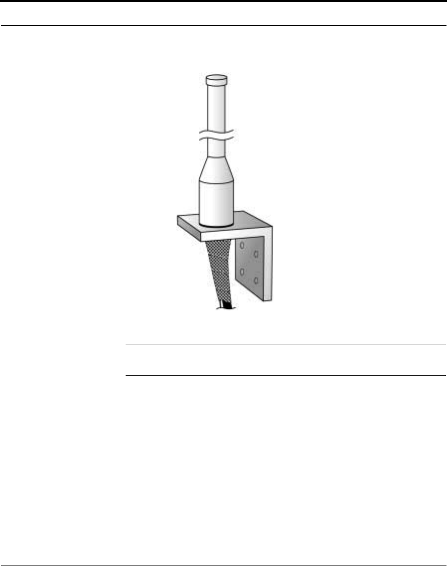
2.6.8 Amplifier Weatherproofing
The amplifier is designed to be mounted outdoors. The connectors must
be weatherproofed using the same technique described for
weatherproofing antenna connections. To prevent rain or snow from
falling directly on the connectors, mount the amplifier with the
connectors facing down. The DC injector is designed to be mounted
indoors and must be protected from moisture and excessive heat and cold.

Nokia RoofTop™ Wireless Routing Installation Guide 21
Indoor Installation Procedures
2.7 Indoor Installation Procedures
The procedures for an indoor installation are the same as those for an
outdoor installation as described in section 2.6, with the following
exceptions:
2.7.1 Weatherproofing
An indoor installation does not require weatherproofing as described in
section 2.6.6. All equipment must be installed away from moisture from
outside doors, open windows, faucets, and so on. Do not install equipment
in bathrooms.
2.7.2 Antennas
For indoor directional panel antenna installations, install the antenna at
least six feet (two meters), high and six feet from human access.
2.7.3 Grounding
The antenna may be appropriately grounded in the building. It does not
require a ground rod connection as described in section 2.6.5.

22 Nokia RoofTop™ Wireless Routing Installation Guide

Nokia RoofTop™ Wireless Routing Installation Guide 23
CHAPTER 3 Wireless Router Installation
3.1 Introduction
A wireless router system consists of two or more antennas, antenna
cables, and wireless routers. One of the units is the AirHead which
connects with wire to the Internet. All other units are Subscriber units that
connect to remote computers or LANs. This chapter describes how to
connect the system and verify the hardware installation.
3.1.1 Preinstallation Requirements
•Professional installers are responsible for moving and re-installing all
equipment.
•All antenna installations on towers require licensed tower climbers.
•Use only Nokia approved accessories for all installations.
•Ground the antenna support to a ground rod or other suitable earth
ground.
•Avoid placing the wireless router unit in excessively hot, cold, dusty,
wet, or humid environments.

24 Nokia RoofTop™ Wireless Routing Installation Guide
•The wireless router must be installed with its mounting bracket
whether it is placed on a wall or desktop. The holder provides
ventilation and helps drain spilled liquids.
•Place the wireless routers DC power unit out of the way, or tape it to
the side of a vertical surface to prevent it from being stepped on or
damaged.
•The wireless router can cause interference to (and interfere with)
other devices operating in the 2.4 to 2.4835 GHz radio spectrum.
•Changing the Ethernet configuration from a LAN connection to a
direct PC connection requires changing from a standard Ethernet
cable to a crossover cable.
NOTE: The Nokia RoofTop™ Wireless Router and its associated
components are Class B devices that must be installed by a professional.
3.1.2 Physical Location
Wireless routers must be installed indoors.
Install the wireless router as close to the entry point of the RF cable into
the building as is practical. Keep the cable length from the antenna to the
wireless router as short as possible.
Ambient temperature must be 32-104 degrees Fahrenheit. Avoid
mounting the wireless router in an environment that gets extremely hot.
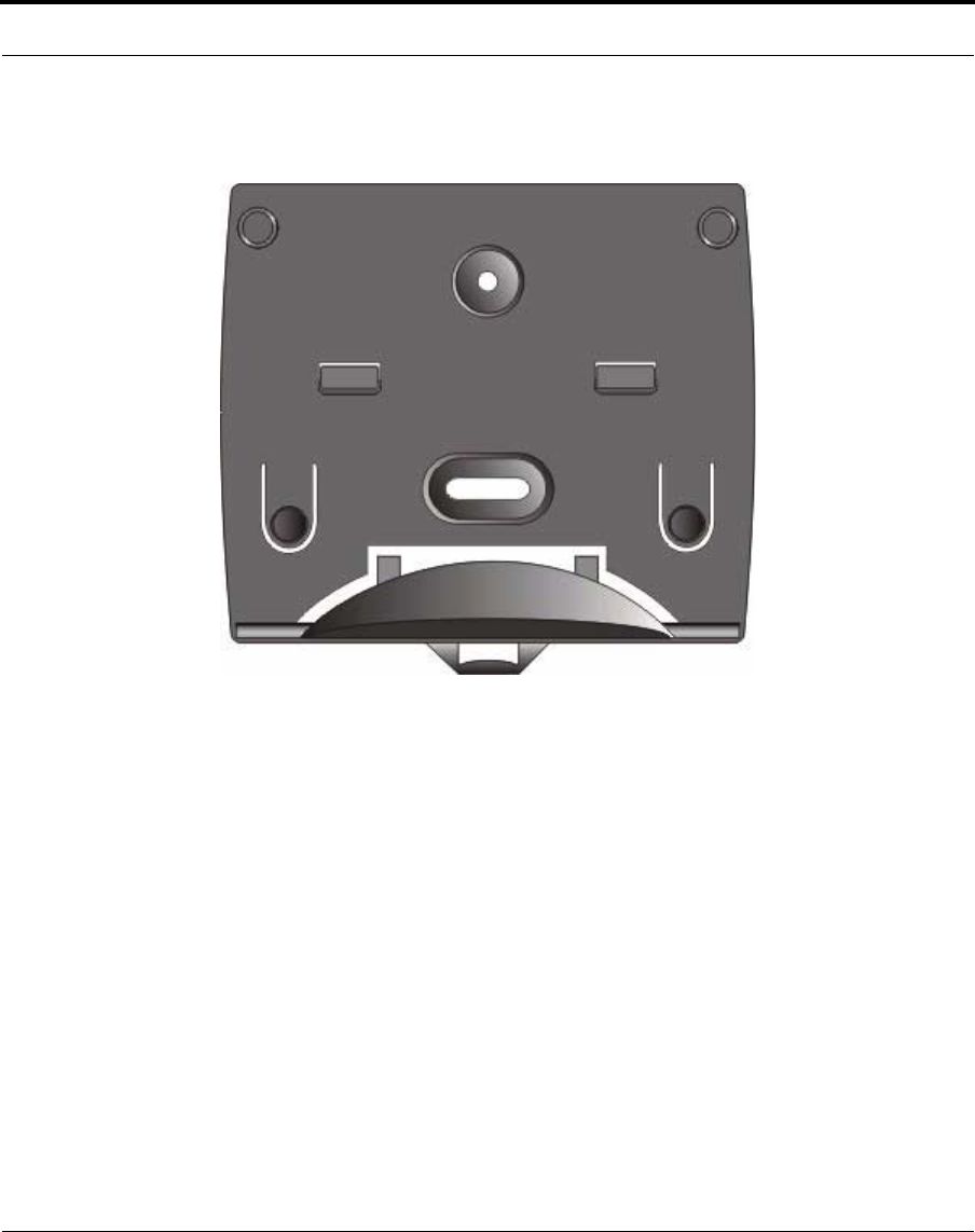
3.1.3 Physical Mounting
The wireless router installs in its mounting bracket. Securely attach the
mounting bracket to a wall or flat surface with two screws. Typical
mounting is vertical with the mounting flange and cable strain relief
facing down. This forces the RF cable to bend and extend below the
wireless router, creating a “drip loop”. Drip loops prevent water from
running down the RF cable and into the wireless router.
Nokia RoofTop™ Wireless Routing Installation Guide 25
Introduction
Mounting Bracket
3.1.4 Connection Options
There are two ways to connect the wireless router to the subscriber’s
network/PC:
1. Network connection
2. Direct Personal Computer connection
3.1.4.1 Network
Use a standard Ethernet cable with an RJ45 connector at the wireless
router and the appropriate connector at your LAN Ethernet connection.

26 Nokia RoofTop™ Wireless Routing Installation Guide
3.1.4.2 Network Connection
Connect an Ethernet crossover cable between the wireless router and the
Personal Computer Ethernet connection. Use an RJ45 connector at the
wireless router and the appropriate connector for your Personal Computer
Ethernet connection.
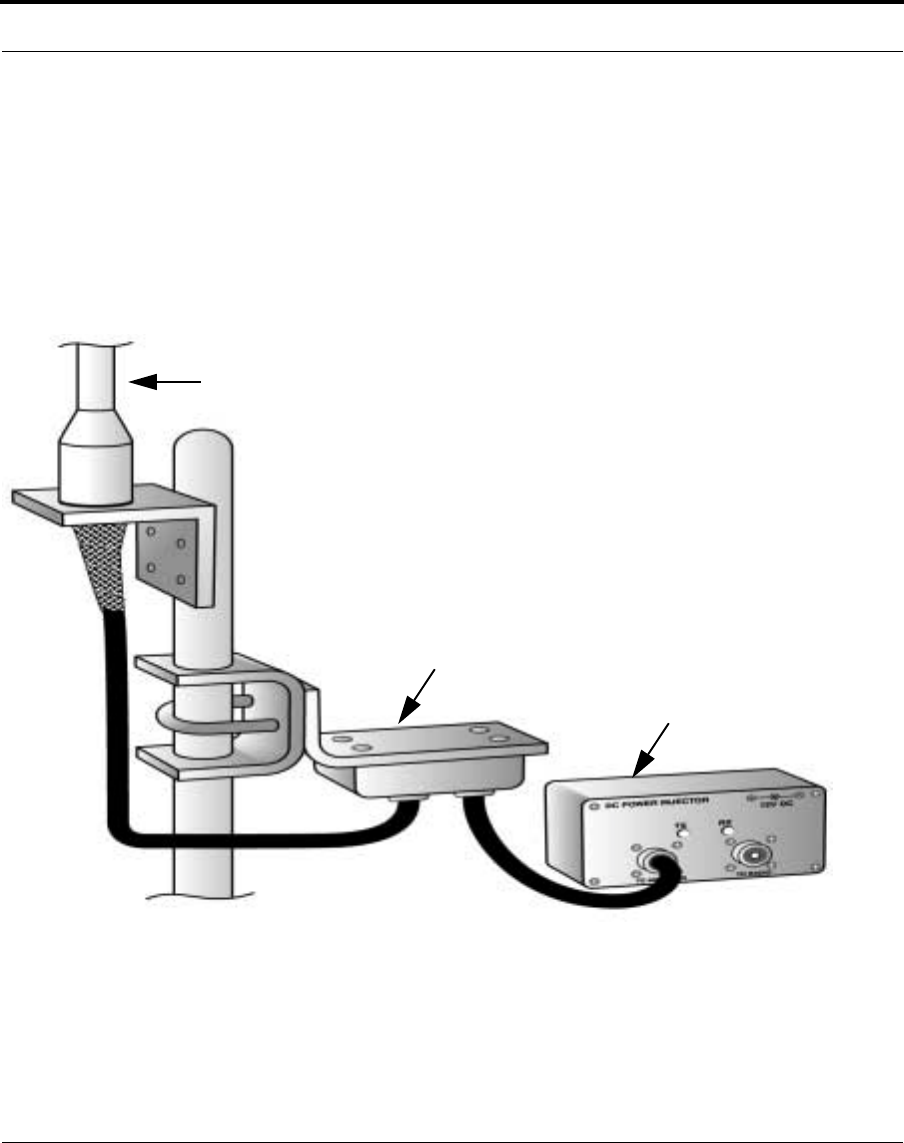
3.1.5 Amplifiers
Amplifiers may be used in some installations. An Amplifier kit consists
of the amplifier, which is mounted next to the antenna, and a DC injector,
which requires AC power, and is mounted indoors next to the wireless
router. Flexible RF jumpers connect the antenna cable to the amplifier
and connect the wireless router to the DC injector. Low-loss RF cable
connects the DC injector to the amplifier, usually through a small jumper
cable.
NOTE: Use only amplifiers supplied by Nokia and certified for use with
the wireless router. Use of any other amplifier is a violation of FCC rules.
Nokia RoofTop™ Wireless Routing Installation Guide 27
Introduction
DC Injector (Mounts Indoors)
Amplifier
Antenna
Amplifier Wiring
28 Nokia RoofTop™ Wireless Routing Installation Guide
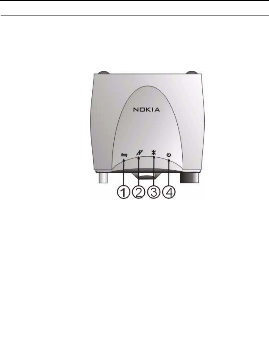
3.2 Front Panel
3.2.1 LED Indicators
1. LAN: Blinking indicates packets are being transmitted between the
wireless router and the LAN or PC.
2. Radio: Blinking indicates packet transmission and reception over the
wireless interface.
3. Anchor: If the configured device is the AirHead, there will be no
indication until another wireless router is configured. If the device is a
remote, the following LED indications occur:
Front Panel
Wireless Router

Nokia RoofTop™ Wireless Routing Installation Guide 29
Front Panel
•LED steady on: The link to the next-hop (neighbor) in the path to the
AirHead has a Data Rate of two Mbps and the path is <=3 hops.
•Slow Flash - The link to the next-hop (neighbor) in the path to the
AirHead has a Data Rate of one Mbps and the path is <=3 hops.
•Fast Flash - Either
•Connected to one or more neighbors but not to an AirHead, or
•Connected to an AirHead with four or more hops in the path.
•LED off - The router has no neighbors.
4. Power Steady on: the wireless router is on.
3.2.2 Configuration
Refer to the Nokia Wireless Router Manager Configuration Guide for
configuration instructions.
30 Nokia RoofTop™ Wireless Routing Installation Guide
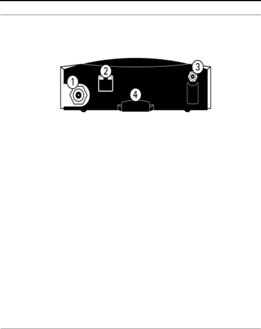
3.3 Rear Panel
1. Antenna Connector: Connect a small vertical antenna directly to the
antenna jack or connect a cable to an external antenna. The connector
is a reverse-polarized TNC female unit. You may need a jumper
converter to attach cables to the wireless router. Most cables are
supplied with reverse-polarized TNC male connectors. For systems
with an amplifier, connect a small jumper cable to the DC Injector
“To Radio” connector.
2. LAN: The LAN interface is a standard 10/100 BaseT Ethernet RJ45
jack. Connect the LAN interface on the wireless router to either:
•The network using a standard Ethernet cable, or
•A PC via an Ethernet crossover cable.
See Appendix A for a wiring description for the Ethernet crossover
cable.
3. Power Port: Connects the wireless router to the 12 VDC power
connector.
4. Strain Relief: For the 12 VDC power cable.
Rear Panel Connections
Wireless Router

Nokia RoofTop™ Wireless Routing Installation Guide 31
APPENDIX A Cables
Ethernet Crossover Cable
The wiring for an Ethernet Crossover cable for 10Base-T is as follows:
RJ45 Plug
Pin 1 (Tx+) to Pin 3 (Rx+)
Pin 2 (Tx-) to Pin 6 (Rx-)
Pin 3 (Rx+) to Pin 1 (Tx+)
Pin 6 (Rx-) to Pin 2 (Tx-)

32 Nokia RoofTop™ Wireless Routing Installation Guide

Nokia RoofTop™ Wireless Routing Installation Guide 33
APPENDIX B Network Planning Guidelines
This appendix includes Network Planning Guidelines for Nokia
RoofTop™ Wireless Routers.
To maintain broadband speeds in a Nokia RoofTop™ Wireless network
follow these guidelines:
•Keep networks within three hops of the AirHead
•Do not connect more than 40 subscriber units to each AirHead
•Do not connect more than 6 networks to each AirHead
NOTE: Subscribers that are one hop away from the AirHead that act as a
relay for customers behind them should have 2Mbps links.
NOTE: Subscribers who are two or three hops from the AirHead can
have 1Mbps links without negatively affecting their performance, provided
they do not act as a repeater for more than two other subscribers.

34 Nokia RoofTop™ Wireless Routing Installation Guide

Nokia RoofTop™ Wireless Routing Installation Guide 35
APPENDIX C Technical Specifications
This appendix describes technical specifications for Nokia RoofTop™
Wireless Routers R242/242A.
Typical Minimum Maximum
Transmit Power without
Amplifier (dBm)a25.2 23.0 26.5
Transmit Power with
Amplifier (dBm)b29 28 30
Receiver Sensitivity
(dBm) -72 -70.5 -73
Ambient Temperature
Range Celsius
Fahrenheit
0
32
40
104
Raw Channel Data
(Mbps) 1 & 2 (Adaptive)
RF Frequency Band 2.400 to 2.479 GHz, frequency hopping, spread spectrum
RF Signal Bandwidth 1 MHz
RF Channels 12 non-overlapping hopping sets with 6 channels per set
Modulation Type 4-Level GFSK Frequency Hopping Spread Spectrum
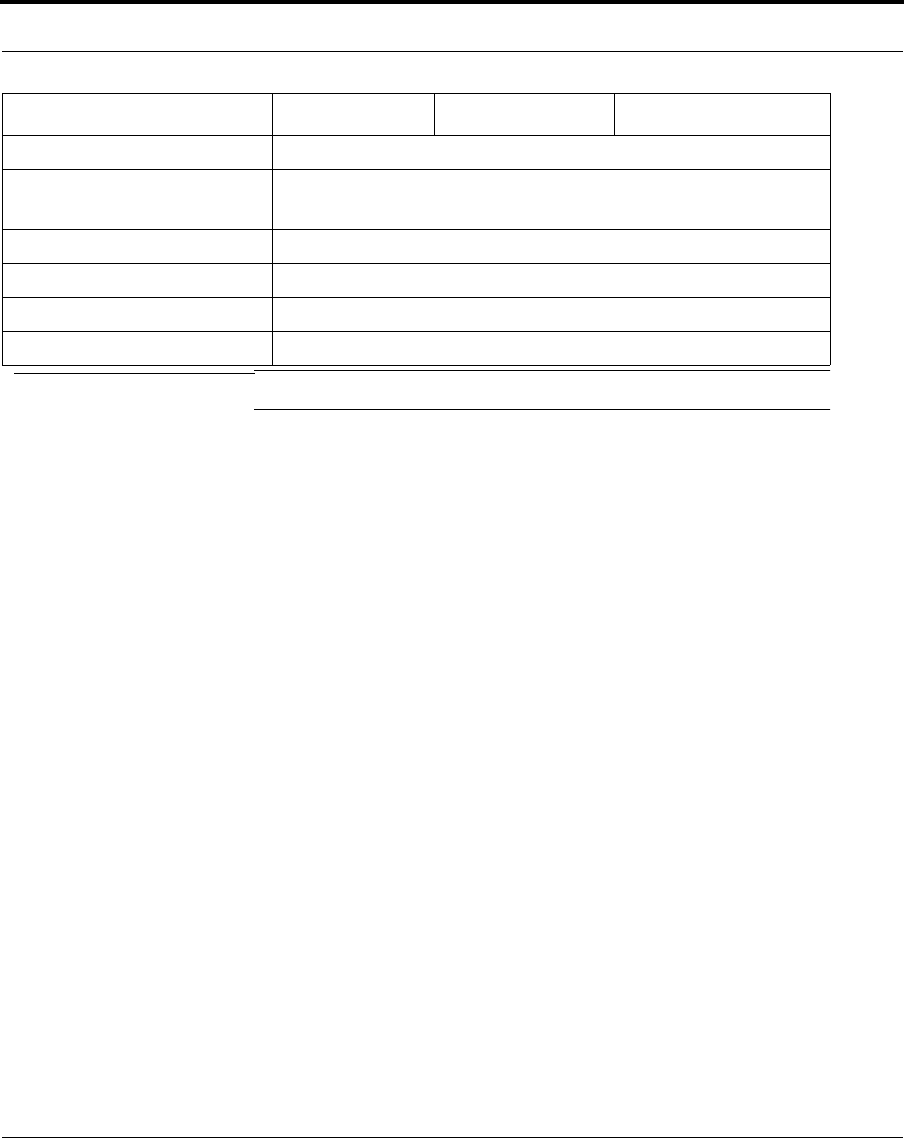
36 Nokia RoofTop™ Wireless Routing Installation Guide
LAN Interface 10/100Mbps Ethernet, RJ45 connector
Internet Protocols IP, TCP, UDP, ICMP, SLIP, PPP, RIPv1, RIPv2, SNMP,
TFTP, IGMP, ARP, Proxy-ARP, Telnet
Power 12VDC
Dimensions 5 1/4"W x 4 1/2"D x 1 1/2"H
Weight 9 ounces
Router RF Connector TNC female
a.As measured at the RF output connector of the radio, excluding cable loss.
b.As measured at the RF output connector of the amplifier, excluding cable loss.
Typical Minimum Maximum

Nokia RoofTop™ Wireless Routing Installation Guide 37
Index
A
Antenna Installation
Grounding 15
Polarization 14
Required Installation Components 13
Safety Guidelines 13
Weatherproofing 16
Jumper Connection 19
Steps 16
Supplies 16
Antenna Selection
Directional Antennas 10
Omnidirectional Antennas 10
F
Fresnel Zone 9
Front Panel
LED Indicators 28
Front Panel Diagram 28
H
Hardware Installation
Antenna Connector 30
Connection
Network 25
Physical Location 24
Physical Mounting 24
Preinstall Requirements 23
L
LAN Interface 26
Line of Sight Analysis
Fresnel Zone 9
Radio Line of Sight 9
Visual Line of Sight 8
P
Power Port 30
S
Site Analysis 6
RF Link Feasibility 6
Site Survey Steps 6