Nordic ID NUR10W Nordic ID UHF RFID Reader NUR-10W User Manual
Nordic ID Oy Nordic ID UHF RFID Reader NUR-10W Users Manual
Contents
Users Manual
1
2016-03-18
NUR-10W HW Implementation Guide v1.4
NUR-10W HW IMPLEMENTATION GUIDE
2
2016-03-18
NUR-10W HW Implementation Guide v1.4
Change history:
Version
Date
Author
Remarks
1.0
16.4.2014
Toni Heijari
First released version
1.1
26.10.2015
Toni Heijari
Added 6.5 and 6.6, modified sections 5.3, 5.3
and 9.4.
1.2
26.01.2016
Jarmo Nurmela
Updated Regulatory agency information
section
1.3
8.2.2016
Toni Heijari
Updated section 4.1.
1.4
4.3.2016
Toni Heijari
Updated Regulatory agency information
section

3
2016-03-18
NUR-10W HW Implementation Guide v1.4
Table of contents
1 GENERAL DESCRIPTION ......................................................................................................................... 5
1.1 Block diagram .................................................................................................................................... 5
1.2 Key features ...................................................................................................................................... 5
1.3 Typical application schematics .......................................................................................................... 6
2 ELECTRICAL CHARACTERISTICS ........................................................................................................................ 7
2.1 Absolute maximum ratings ................................................................................................................ 7
2.2 DC characteristics ............................................................................................................................. 7
2.3 RF characteristics .............................................................................................................................. 7
2.4 Performance characteristics .............................................................................................................. 8
3 PIN ASSIGNMENTS ......................................................................................................................................... 9
3.1 Pin designation .................................................................................................................................. 9
3.2 Pin mapping ....................................................................................................................................... 9
3.3 Signal description ............................................................................................................................ 11
4 OEM DESIGN CONSIDERATIONS .................................................................................................................... 13
4.1 RF output and antenna requirements ............................................................................................. 13
4.1.1 Layout recommendations .................................................................................................. 13
4.1.2 Transmission line .............................................................................................................. 14
4.2 Power supply ................................................................................................................................... 14
4.3 USB device port............................................................................................................................... 15
5 RF PARAMETERS .......................................................................................................................................... 16
5.1 TX level ............................................................................................................................................ 16
5.2 Receiver sensitivity .......................................................................................................................... 16
5.3 Leakage cancellation (AKA antenna tuning) ................................................................................... 17
5.4 Modulation ....................................................................................................................................... 17
5.5 Link frequency ................................................................................................................................. 17
5.6 RX encoding (Miller encoding) ........................................................................................................ 18
5.7 Region ............................................................................................................................................. 19
6 READING PARAMETERS ................................................................................................................................ 21
6.1 Q-value ............................................................................................................................................ 21
6.2 Session ............................................................................................................................................ 21
6.3 Rounds ............................................................................................................................................ 22
6.4 Selecting the right reading parameters ........................................................................................... 22
6.5 RSSI FILTERS ................................................................................................................................ 23
6.6 Dynamic Power save modes ........................................................................................................... 24
7 GPIO CONFIGURATIONS ............................................................................................................................... 25

4
2016-03-18
NUR-10W HW Implementation Guide v1.4
7.1 Input / output.................................................................................................................................... 25
7.2 Predefined functions ........................................................................................................................ 25
8 DIAGNOSTIC FUNCTIONS .............................................................................................................................. 27
8.1 Reflected power measurements...................................................................................................... 27
8.2 Channel scanner ............................................................................................................................. 27
8.3 Received signal strength (RSSI) ..................................................................................................... 27
9 DIMENSIONS ............................................................................................................................................... 28
9.1 Mechanical dimensions ................................................................................................................... 28
9.2 Land pattern .................................................................................................................................... 30
9.3 Paste stencil .................................................................................................................................... 32
9.4 Packing tray dimensions ................................................................................................................. 34
10 SMT ASSEMBLY PROCESS AND THERMAL PROCESSING ................................................................................... 35
10.1 Storage conditions ........................................................................................................................... 35
10.2 Soldering process ............................................................................................................................ 36
11 REGULATORY AGENCIES INFORMATION ........................................................................................................ 38
11.1 European Union and EFTA countries ............................................................................................. 38
User’s Guide Requirements ................................................................................................................ 38
Labeling Requirements ....................................................................................................................... 41
Approved Antennas ........................................................................................................................... 41
11.2 FCC ................................................................................................................................................. 42
User’s Guide Requirements ................................................................................................................ 44
Labeling Requirements ....................................................................................................................... 44
Approved Antennas ........................................................................................................................... 44
11.3 Industry Canada .............................................................................................................................. 45
Labelling Requirements for the Host device ......................................................................................... 46
certified Antennas ............................................................................................................................. 46
11.4 Industrie Canada ............................................................................................................................. 47
Exigences applicables aux appareils hôtes ............................................................................................ 48
TYPES D'ANTENNES ACCEPTABLES ....................................................................................................... 49
5
2016-03-18
NUR-10W HW Implementation Guide v1.4
1 GENERAL DESCRIPTION
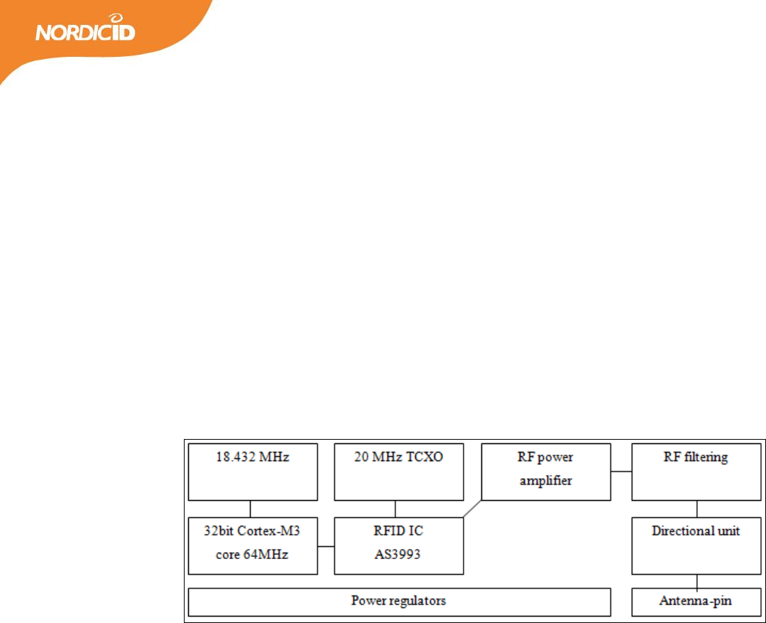
NUR-10W is a next generation compact UHF RFID reader / writer module. It is compatible with
ISO18000-6C (EPC C1G2) standard. Module fulfills ETSI, FCC and IC radio regulations. It is also
compatible with DRM (dense reader mode) requirements. Maximum output power is +30dBm and it
can be adjusted via SW API with 1 dB steps. Maximum sensitivity LBT / data is -80/-70 dBm. The
sensitivity can also be adjusted.
1.1 BLOCK DIAGRAM
Figure 1. Block diagram of the module
1.2 KEY FEATURES
SMT compatible module with small footprint
ISO 18000-6C (EPC C1G2) full protocol support + custom commands
Low power consumption with high noise rejection
DRM compatible
High performance with +30dBm output power, adjustable by 1dB steps
Approved by ETSI, FCC and IC telecommunication organizations
Selectable RF parameters; RX coding, link frequency and modulation
UART and USB 2.0 communication
5 programmable GPIO with event trigger
Autosensing inventory parameter support
Increased sensitivity with automatic leakage cancelation
6
2016-03-18
NUR-10W HW Implementation Guide v1.4
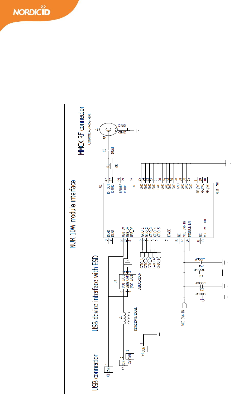
1.3 TYPICAL APPLICATION SCHEMATICS
Typical application schematic including: USB connection with ESD protection circuitry, 2
GPIO outputs for LED indicators, GPIO trigger input, NUR-10W module and MMCX antenna
connector.
Figure 2. A simple application schematic.
7
2016-03-18
NUR-10W HW Implementation Guide v1.4
2 ELECTRICAL CHARACTERISTICS
2.1 ABSOLUTE MAXIMUM RATINGS
Violating these values may cause damage to the module. Also correct operation is not guaranteed if
operating outside these values. NUR-10W is ESD sensitive component so it must be handled with care.
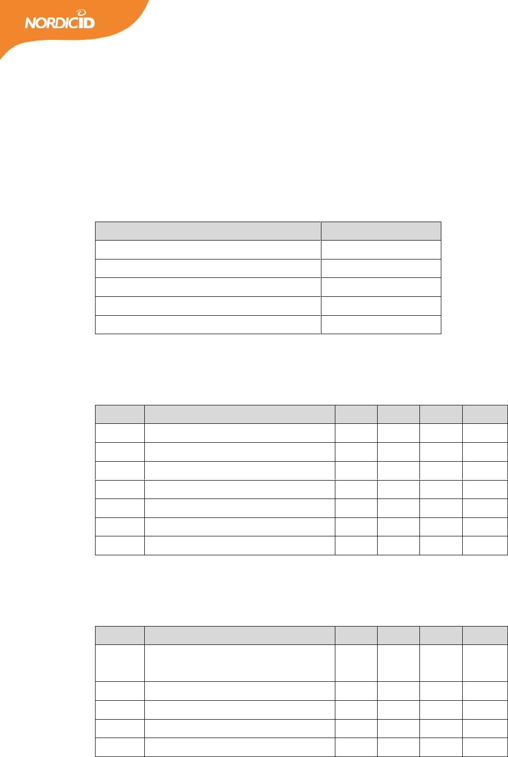
Table 1. Absolute maximum ratings of the module.
Absolute maximum ratings
Value
Operating temperature
-20°C to +55°C
Storage temperature (package unopened)
-30°C to +85°C
Supply voltage and enable
+6.0V
GPIO pins
+4.0V
Other pins
+4.0V
2.2 DC CHARACTERISTICS
Table 2. DC characteristics (VCC_3V6_IN = 3.6V @ +25°C).
Symbol
Parameter
Min
Typ
Max
Units
Vext
Supply voltage
3.4
3.6
5.5
V
Iext
Supply current
-
1.2
-
A
Isource
GPIO source current
-
-
3
mA
Isink
GPIO sink current
-
-
6
mA
Vlow
GPIO input low-level voltage
-
-
0.8
V
Vhigh
GPIO input high-level voltage
2.0
-
-
V
Ven
Module enable voltage
1.2
-
Supply
V
2.3 RF CHARACTERISTICS
Table 3. RF characteristics (VCC_3V6_IN = 3.6V @ +25°C).
Symbol
Parameter
Min
Typ
Max
Units
Sens
Receiver sensitivity (data sensitivity
PER=0.1% / LBT sensitivity)*
-
-
-70/-80
dBm
Pout
Output power
11±2
-
30±1
dBm
Padj
Power adjustment step
-
1
-
dB
S11
VSWR requirement
-
-
1,5:1
@50Ω
Drt
Reader to tag data rates
-
40 / 80
-
kbps
8
2016-03-18
NUR-10W HW Implementation Guide v1.4
Dtr
Tag to reader data rates
20
64
320
kbps
*Sensitivity is measured at the RF-port of the module with leakage cancellation activated. The actual
receiver sensitivity is 10dB better due to 10dB coupler loss in RX-path.
2.4 PERFORMANCE CHARACTERISTICS
The performance of the reader module is highly dependent on the test environment, reader antenna and
tag performance. Interferences from other radio sources operating in the same frequency may decrease the
performance. Also the tag antenna and the tag IC may have significant effect on the values presented
below. Also selected radio and inventory parameters have got a big influence to reading performance.
Table 4. Performance characteristics (VCC_3V6_IN = 3.6V @ +25°C).
Symbol
Parameter
Min
Typ
Max
Units
Rdist
Typical reading distance with 5 dBi antenna
-
5
-
m
Rrate
Typical reading rate (Tari25 / Tari12.5)
-
200/300
-
tags/s
Otemp
Operation temperature
-20
-
+55
°C
Hrel
Relative humidity
10
-
95
%
9
2016-03-18
NUR-10W HW Implementation Guide v1.4
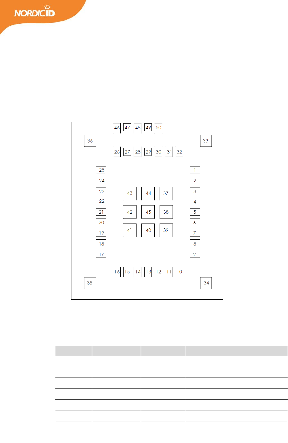
3 PIN ASSIGNMENTS
3.1 PIN DESIGNATION
Figure 3. Through top view.
3.2 PIN MAPPING
Table 5. Pin mapping of the module.
Pin number
Signal name
Pin type
Description
1
RFU
Bidirectional
RFU (do not connect)
2
GPIO_5
Bidirectional
3.3V GPIO
3
GPIO_4
Bidirectional
3.3V GPIO
4
GPIO_3
Bidirectional
3.3V GPIO
5
GPIO_2
Bidirectional
3.3V GPIO
6
GPIO_1
Bidirectional
3.3V GPIO
7
ERASE
Input
DNU (do not use)
8
RX
Input
Data from Host to Module

10
2016-03-18
NUR-10W HW Implementation Guide v1.4
9
TX
Output
Data from module to Host
10
USB_DN
Bidirectional
USB – (device port)
11
USB_DP
Bidirectional
USB + (device port)
12
USB_DET
Input
Used only for USB detection
13
VCC_3V3_OUT
Supply output
DNU (only for testing purposes)
14
MODULE_EN
Input
Driving high will enable the module
15
GND
Supply input
Ground
16
NC
Not connected
internally not connected
17
VCC_3V6_IN
Supply input
Supply voltage input
18
RFU
Bidirectional
RFU (do not connect)
19
RFU
Bidirectional
RFU (do not connect)
20
GND
Supply input
Ground
21
GND
Supply input
Ground
22
GND
Supply input
Ground
23
GND
Supply input
Ground
24
GND
Supply input
Ground
25
GND
Supply input
Ground
26
GND
Supply input
Ground
27
RFU/RF
Bidirectional
RFU (do not connect)
28
GND
Supply input
Ground
29
RFU/RF
Bidirectional
RFU (do not connect)
30
GND
Supply input
Ground
31
NC
Not connected
internally not connected
32
NC
Not connected
internally not connected
33-46
GND
Supply input
Ground
47
RF
Bidirectional
50Ω RF output/input
48
GND
Supply input
Ground
49
RFU/RF
Bidirectional
RFU (do not connect)
50
GND
Bidirectional
Ground
11
2016-03-18
NUR-10W HW Implementation Guide v1.4
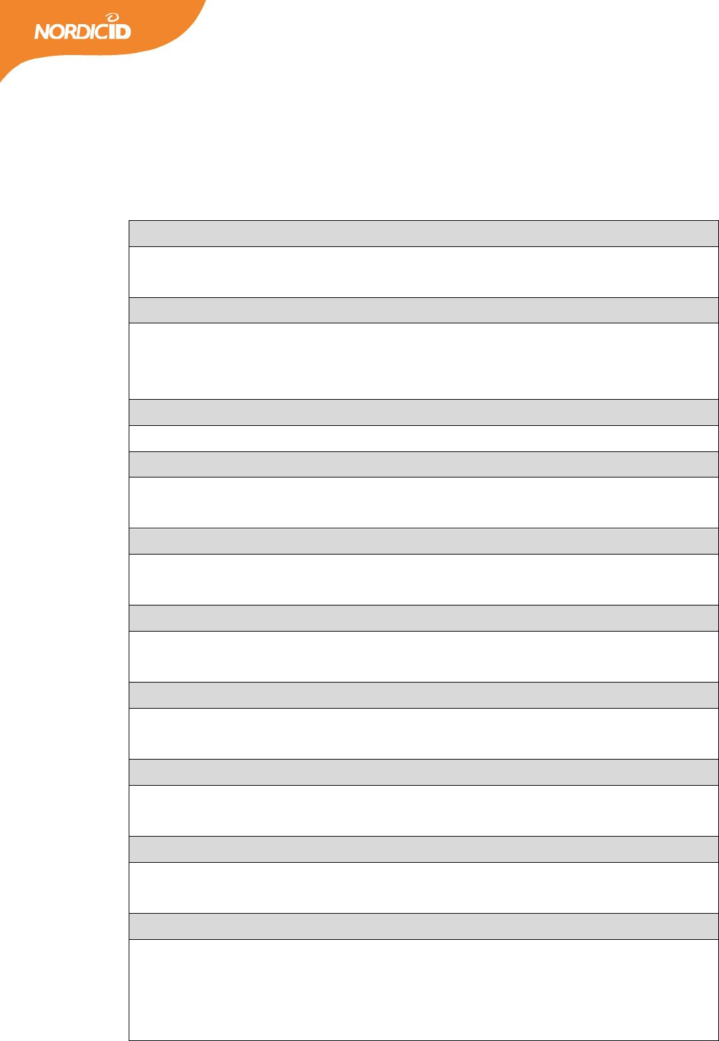
3.3 SIGNAL DESCRIPTION
Table 6. Signal description.
Signal name: GND Pin number(s): 15, 20-26, 28, 30, 33-46, 48, 50
These pins are used for grounding and to improve the thermal performance. They should be
connected to Host board GND net.
Signal name: GPIO_X Pin number(s): 2-6
These pins are used as general purpose IO. They can be configured via SW API as input or output
ports. IO voltage level is 3.3V. GPIOs have source current capability of 3mA and sink current capability
of 6mA.
Signal name: ERASE Pin number(s): 7
This pin is used for production testing purposes only. Should not be connected.
Signal name: RX Pin number(s): 8
This pin is used for module UART input signal. Logic level is 3.3V. If UART is used for communication
the pin should be connected to the Host MCU serial TX port.
Signal name: TX Pin number(s): 9
This pin is used for module UART output signal. Logic level is 3.3V. If UART is used for communication
the pin should be connected to the Host MCU serial RX port.
Signal name: USB_DN Pin number(s): 10
This pin is used as USB_D- device port. It is advised to use external ESD protection component if
connected to user accessible USB connector.
Signal name: USB_DP Pin number(s): 11
This pin is used as USB_D+ device port. It is advised to use external ESD protection component if
connected to user accessible USB connector.
Signal name: USB_DET Pin number(s): 12
This pin is only used for USB connection detection. It is advised to use external ESD protection
component if connected to user accessible USB connector. Current is not drawn from this input pin.
Signal name: VCC_3V3_OUT Pin number(s): 13
This pin is connected to internal power regulator output. The pin is used for production testing and it
should not be used.
Signal name: MODULE_EN Pin number(s): 14
Driving this pin to high will enable the NUR-10W module. It is internally connected to onboard voltage
regulator’s enable input. The trigger level is 1.2V and the reader module will wake up in 50ms. If the
external power switch is used to toggle ON and OFF, this pin can be connected directly to
VCC_3V6_IN.

12
2016-03-18
NUR-10W HW Implementation Guide v1.4
Signal name: NC Pin number(s): 16, 31, 32
These pins are internally not connected.
Signal name: VCC_3V6_IN Pin number(s): 17
This pin is used for power supply input for NUR-10W module. It is recommended to use 200µF (low
ESR) 100nF and 100pF capacitor near the VCC_3V6_IN input pin to maintain stable operating voltage
for the reader module.
Signal name: RFU / RFU/RF Pin number(s): 1, 18, 19, 27, 29, 49
These pins are reserved for future use. Do not connect these pins.
Signal name: RF Pin number(s): 47
50Ω impedance RF output / input pin. Trace to this pin should be also matched to 50 Ω. See more
details from the design considerations section.
13
2016-03-18
NUR-10W HW Implementation Guide v1.4
4 OEM DESIGN CONSIDERATIONS
4.1 RF OUTPUT AND ANTENNA REQUIREMENTS
The RF output / input impedance is 50Ω so the trace leaving from the RF pin shall be kept in that same
impedance level to avoid reflections and mismatch of the RF signal. From the RFID reader module’s point of
view it is important that the used antenna has a low VSWR value. The VSWR shall be better than 1.5:1 in
order to avoid decrease in the sensitivity performance of the receiver because of the TX power reflecting
back from the antenna. In the NUR-10W module, there is also an automatic leakage cancellation system
that decreases the effect of the reflected signal, and it also improves the isolation of the RX signal from the
TX signal. The automatic leakage cancellation can be triggered using SW API command. For further
information on the leakage cancellation see the section 5.3.
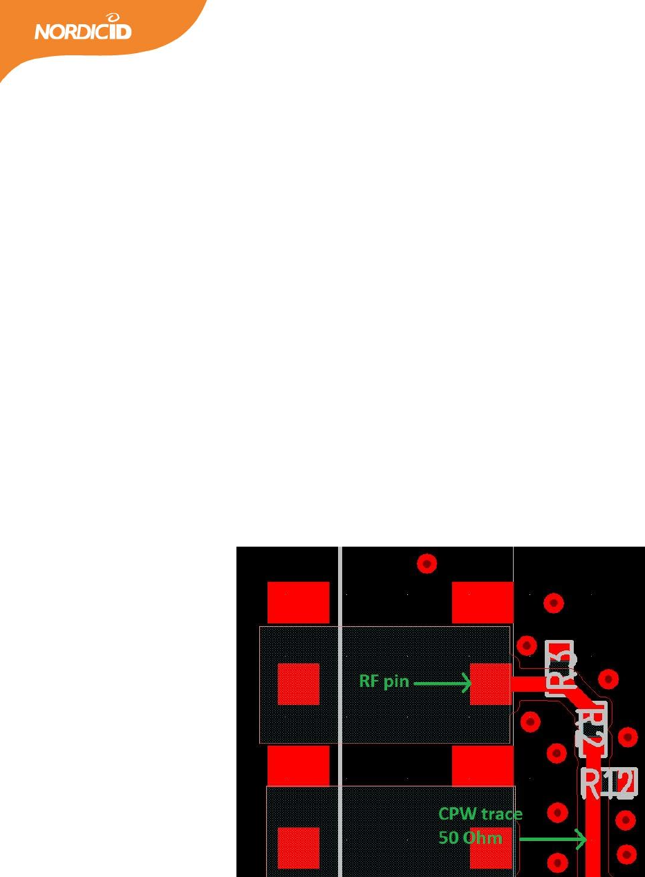
4.1.1 LAYOUT RECOMMENDATIONS
Figure 4. RF output layout of the reference design.
Component places R2, R3, and R12 are for additional output matching. Additional matching is not used in a
reference design. Thus values are as follow: R3 = No assembly, R12 = No assembly and R2 = 100pF 0402
capacitor.
Because NUR-10W is a wireless device, the RF section must be the top priority in terms of layout. It is very
important that the layout design is made by following the proper RF design guidelines to get to optimal
14
2016-03-18
NUR-10W HW Implementation Guide v1.4
performance from the device. Poor layout design can decrease the output power, sensitivity and cause
mask violations.
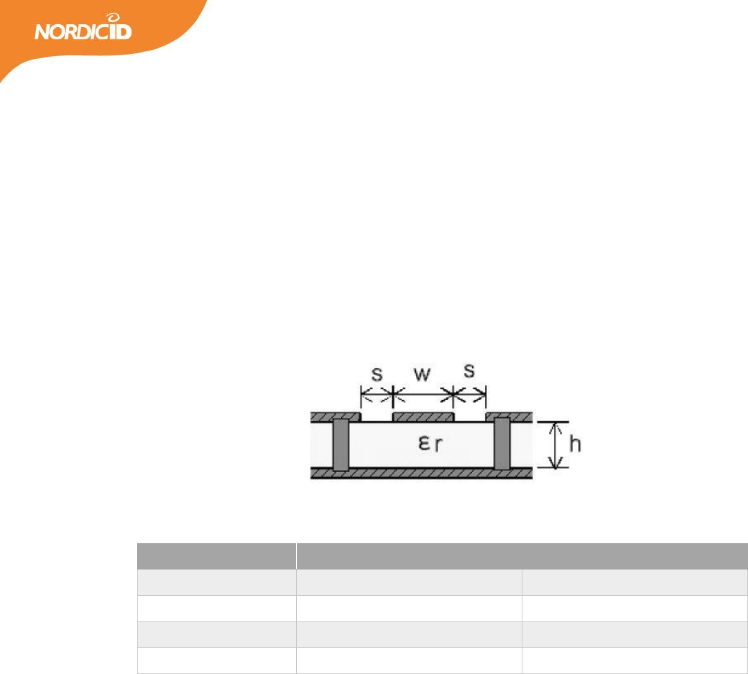
4.1.2 TRANSMISSION LINE
The RF signal from the module is routed to antenna connector using a grounded CPW structure. This is to
achieve the maximum isolation and RF shielding to RF lines. Also GND vias should be added along the line to
give additional shielding.
Figure 5. Grounded CPW with via stitching.
Table 7. Recommended PCB values for 4-layer board (L2 is the GND plane for transmission line)
Parameter
Value
Unit
W
0.35
mm
S
0.2
mm
h
0.18
mm
εr
4
General recommendations:
1. RF traces must have 50 Ohm impedance because module is only rated to operate in 50 Ohm systems.
2. RF trace bends must be gradual and not have any sharp corners.
3. Grounded CPW structure must have GND via stitching.
4. Only connect antennas which are approved.
4.2 POWER SUPPLY
The NUR-10W has internal linear power regulators for getting better power supply noise rejection. However
it is still important to supply low noise and stable power to the NUR-10W module. The voltage ripple should
be kept under 200mVpp and it is recommended to add a minimum of 200µF low ESR, 100nF and 100pF
capacitors next to the VCC_3V6_IN pin.
15
2016-03-18
NUR-10W HW Implementation Guide v1.4
VCC_3V3_OUT is internal regulator output and it is used for production testing purposes. This pin should
not be used to power external circuits.
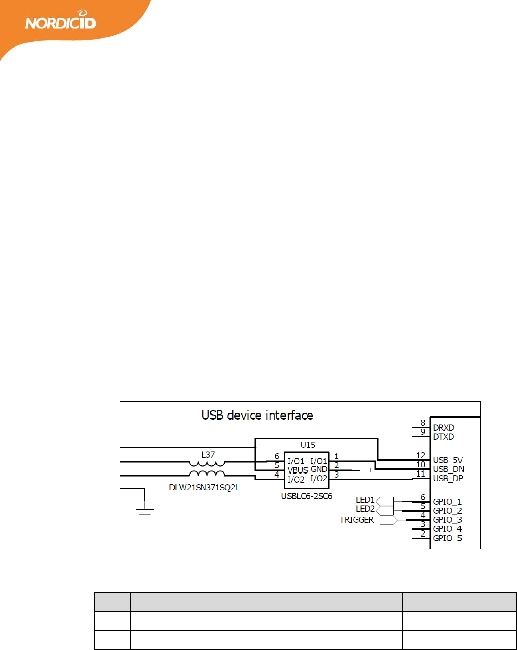
4.3 USB DEVICE PORT
USB_DP, USB_DN and USB_DET pins are used to provide 2.0 compliant USB device port. It must be
remembered that only one communication method can be used to communicate with the NUR-10W
module at the time. Connecting the USB will automatically prevent communication via serial port. It is
advised to use external ESD protection component if connected to user accessible USB connector. Below is
the typical schematics used with NUR-10W module.
Figure 6. Typical schematics for USB connection with ESD protection.
Table 8. Used components.
Ref
Description
Manufacturer
Part code
U15
ESD protection
ST Microelectronics
USBLC6-2SC6
L37
Common mode choke
Murata
DLW21SN371SQ2L
16
2016-03-18
NUR-10W HW Implementation Guide v1.4
5 RF PARAMETERS
5.1 TX LEVEL
The maximum output power is +30dBm (1000mW). The power can be adjusted by 1dB steps. In total there
are 19 steps meaning the minimum output power value is +11dBm that equals to 13mW of power. When
using higher output power levels the antennas VSWR value becomes more and more important factor. High
output power combined together with antenna with poor VSWR leads to a situation where significant
portion of the power is reflected back to the receiver.
Table 9. TX power levels.
TX level
Power: dBm / mW
TX level
Power: dBm / mW
0
30 / 1000
10
20 / 100
1
29 / 794
11
19 / 79
2
28 / 631
12
18 / 63
3
27 / 500
13
17 / 50
4
26 / 398
14
16 / 40
5
25 / 316
15
15 / 32
6
24 / 251
16
14 / 25
7
23 / 200
17
13 / 20
8
22 / 158
18
12 / 16
9
21 / 126
19
11 / 13
5.2 RECEIVER SENSITIVITY
The maximum LBT sensitivity is -80dBm and maximum data sensitivity is -70dBm. The receiver can handle
+5dBm of power reflecting back to RF_OUT pin without having a big impact on the performance. Tolerance
to reflecting signal can be significantly increased using NUR-10W leakage cancellation functionality. The
receiver architecture uses direct conversion and it has an integrated AGC (automatic gain controller).
NUR-10W-module has also capability to adjust the sensitivity of the receiver. This can be useful is some
applications where you want to limit the read range without reducing the actual RF output power. There
are three steps. Low, nominal and high. Those corresponds to absolute sensitivity levels as follows; -50dBm,
-60dBm and -70dBm.

17
2016-03-18
NUR-10W HW Implementation Guide v1.4
5.3 LEAKAGE CANCELLATION (AKA ANTENNA TUNING)
The directional coupler of the internal leakage cancellation circuitry separates transmitted and received
signals. Tuning the directional coupler increases the isolation between TX and RX signals. You may tune the
directional coupler using software; there is an API function of its own for that purpose. Notice that the
tuning does not match the RF_OUT with an antenna so the good VSWR (return loss) of the antenna is an
essential factor of the good performance of the system.
There are two different ways to use the leakage cancellation. First is to use the API command in order to
run the tuning sequence. There are 2 depths; fast and wide. This will affect the amount of different
combinations what the circuitry tries in order to get the best isolation between TX and RX. Wide will take
more time but it usually gets better result so it is recommended to be used. Second option is to use so
called Autotune-functionality. This is a fully automated way to constantly adjust the circuitry. When the
module gets some command where RF needs to be put ON it quickly adjust the tuning circuitry as well. In
this way the module can adjust to different environment changes. And by doing this it always operates in
maximum available performance. You can also set a threshold level for Autotune-function. This means that
before adjustment the module will check that is the tuning value already better than the threshold level
and if it is the tuning sequence is skipped thus making reading faster. Autotune is recommended to be used
to get the best performance. Recommended threshold settings: Nominal sensitivity -10 and High sensitivity
-20.
Manual command is only recommended to be used in production tester of the end product in order to get
good starting point values.
5.4 MODULATION
It is possible to use ASK (amplitude shift keying) or PR-ASK (phase reversed amplitude shift keying)
modulation. Tags that are compliant with ISO18000-6C (EPC C1G2) must support both of these
modulations. The PR-ASK modulation can transfer energy more efficiently to the tag because RF envelope is
high more than it is using ASK modulation. By default the modulation is set to PR-ASK.
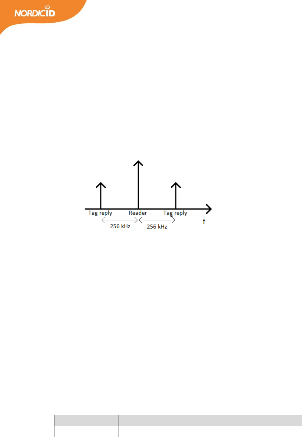
5.5 LINK FREQUENCY
The link frequency affects the frequency offset of tags reply in respect to reader’s carrier wave. For example
when used link frequency is 256 kHz, tag will reply at the frequency of reader transmission frequency ± 256
kHz. The selectable parameters are 160 kHz, 256 kHz and 320 kHz. Tags that are compliant with ISO18000-
6C (EPC C1G2) must support all these parameters. The link frequency also affects tag to reader data rate
which is calculated by formula below:
18
2016-03-18
NUR-10W HW Implementation Guide v1.4
Tag to reader data rate = (Link frequency / Miller coding)
By default the link frequency is set to 256 kHz. 256 kHz or 320 kHz settings must be used when operating in
DRM mode. It must be remembered that changing these parameters may cause reader to violate region or
country specific radio regulations. Following is a guideline for how to choice right setting. If channel
bandwidth is 200 kHz than 256 kHz or lower link frequency should be used (for example in EU). When
operating in a region where 500 kHz channel bandwidth is available also 320 kHz link frequency can be
used.
Figure 7. Spectral separation caused by 256 kHz link frequency and Miller sub-carrier encoding.
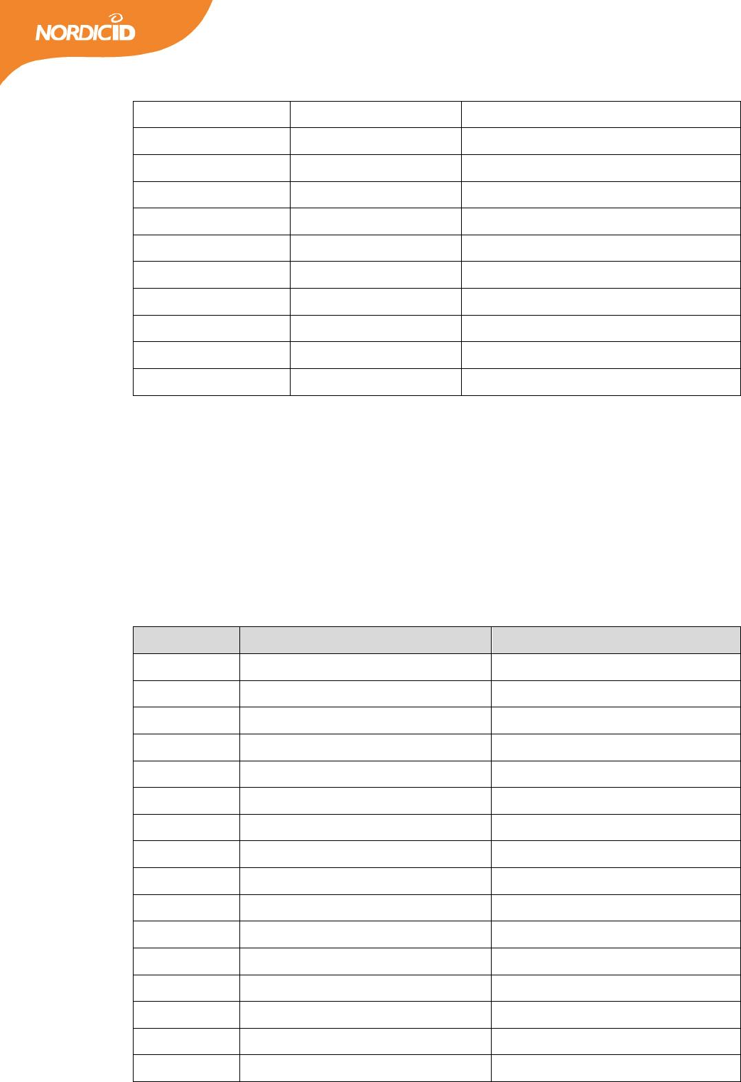
5.6 RX ENCODING (MILLER ENCODING)
Like stated above the Miller sub-carrier encoding scheme affects also tag to reader data rate. In practice the
Miller encoding value affects the number of clock cycles that tag uses to modulate one symbol. So when
using higher Miller encoding schemes tag to reader data rate will be slower but at the same time it is more
robust to interferences. Also tags response spectrum is more concentrated around the link frequency when
using higher Miller schemes. This allows the receiver to use narrower channel filters. Selectable values are
M2, M4, M8 or FM0.
Receiver filters are optimized for M4 and M8 encoding schemes. When operating on DRM mode values 4 or
8 should be used to optimize the performance. By default Miller 4 is used. In addition to miller schemes also
FM0 encoding is supported. In this case link frequency directly determines the tag to reader data rate.
Table 10. Available data rates.
Link frequency (kHz)
RX encoding
Tag to reader data rate (kbps)
160
FM0
160
19
2016-03-18
NUR-10W HW Implementation Guide v1.4
160
M2
80
160
M4
40
160
M8
20
256
FM0
256
256
M2
128
256
M4
64
256
M8
32
320
FM0
320
320
M2
160
320
M4
80
320
M8
40
5.7 REGION
The NUR-10W has predefined region settings defining frequency and channel sets for operating under
different radio regulations. Globally the regulations vary depending on the country or part of the world. The
below table shows the available options for the region and the respective frequency band they use. Note
that the antenna also needs to be working on that same frequency.
Table 11. Pre-programmed fixed countries / regions settings.
Number
Country / region
Frequency / channel BW
0
ETSI / Europe
865.6 – 867.6 MHz / 200kHz
1
FCC / North-America
902 – 928 MHz / 500 kHz
2
People's Republic of China
920.5 – 924.5 MHz / 250 kHz
3
Malaysia
919 – 923 MHz / 500 kHz
4
Brazil
915 – 928 MHz / 500 kHz
5
Australia
920 – 926 MHz / 500 kHz
6
New Zealand
921.5 – 928 MHz / 500 kHz
7
Japan 250mW LBT
916.8 – 923.4 MHz / 200 kHz
8
Japan
916.8 – 920.4 MHz / 200 kHz
9
Korea LBT
917.3 – 920.3 MHz / 500kHz
10
India
865.7 – 866.9 MHz / 200kHz
11
Russia
866.3 – 867.5 MHz / 200kHz
12
Vietnam
920.25 – 924.75 MHz / 500kHz
13
Singapore
920.25 – 924.75 MHz / 500kHz
14
Thailand
920.25 – 924.75 MHz / 500kHz
15
Philippines
918.25 – 919.75 MHz / 500kHz

20
2016-03-18
NUR-10W HW Implementation Guide v1.4
16
Morocco
867.7 – 867.9 MHz / 200kHz
17
Peru
915.25 – 927.75 MHz / 500kHz
18
Custom
840 – 960 MHz
For experimental purposes, it is possible to use custom frequencies and hop tables. Please contact Nordic ID
for further information on how it is possible in your case.
21
2016-03-18
NUR-10W HW Implementation Guide v1.4
6 READING PARAMETERS
6.1 Q-VALUE
The Q-value defines the amount of open response slots that tags can use per one inventory round. Number
of slots can be calculated by formula 2Q. It is advised to use twice as much slots compared to amount of tags
that you have in your readers reading field simultaneously. Selectable values are 0 – 15 and value 0 means
automatic Q-value adjustment. When Q=0 is used reader will automatically increase the Q-value when lots
of collisions are noticed and decreased the value when there are only few collisions. By default the Q-value
is set to 0.
Table 13. Relation between the Q-value and the number of open slots per round.
Q-value
slots
Q-value
slots
0
automatic
8
256
1
2
9
512
2
4
10
1024
3
8
11
2048
4
16
12
4096
5
32
13
8192
6
64
14
16384
7
128
15
32768
6.2 SESSION
There are four session options which you can use when initializing inventory round. Every session has two
target states A and B. By default Gen2 tags are at state A if tag has not been read recently. When tag is read
it flips to state B and doesn’t reply to readers query. The table below describes the persistence of tag’s state
machine when using different session values. For example when using session 0 the tag will come back to
state A immediately when tag power is lost. Usually tag loses the power when reader stops the inventory
round or chances the channel. Persistence when tag power is ON is not defined by the ISO18000-6C when
using session settings S0, S2 and S3. With session 1 the tag will keep it state over 500ms but less than 5s.
With session values 2 and 3 tags will keep it states over 2s when tag power is lost. Time can vary depending
what tag IC is used.
22
2016-03-18
NUR-10W HW Implementation Guide v1.4
Table 14. Persistence characteristics of gen2 tags.
Flag
Persistence: tag power ON
Persistence: tag power OFF
S0
indefinite
none
S1
500ms < t < 5s
500ms < t < 5s
S2
indefinite
t > 2s
S3
indefinite
t > 2s
By changing the target setting from A target to B target reader is able to read also tags that has flipped its
state to B state. This would happen if tags would have been read recently using Session 1 2 or 3. NUR-10W
module also supports dual target mode. In that mode reader will change the target mode between inventory
rounds. By default target mode A is used.
6.3 ROUNDS
The rounds setting defines how many query rounds is done inside one inventory round. After every
inventory round the reader will send data to the Host. Selectable values are 0 – 10. Zero meaning automatic
rounds adjustment. The automatic adjustment decides after every query round whether another round is
necessary based on the number of data collisions. By default rounds setting is set to 0. This setting can help
the reader to find all the tags that are in the readers reading field when using session 0. Because tags that
are found in query round 1 doesn’t replay in the following query rounds. When using session 1/2/3 this
does not make any significant difference because tags that are read are quiet anyway.
Table 15. Relation between inventory round and query round.
Inventory round
Round 1
Round 2
round 3
…
Round 10
6.4 SELECTING THE RIGHT READING PARAMETERS
One approach is to test how many tags are in the readers reading field simultaneously. Keep the reader still
at the position that is as close to real reading environment as possible and see how many tags are found.
Based on that amount choose your open slot number to be 1.5 – 2 times larger (refer to the section 6.1). If
reader will face many different tag populations auto-Q setting will be a good choice.
23
2016-03-18
NUR-10W HW Implementation Guide v1.4
Besides Q-value one important parameter is session. In general it could be stated that if the size of tag
population is measured in thousands rather than in hundreds it is wise to use sessions 2 or 3. Because then
every tag will be read only once and that makes large tag population much faster and easier to read. When
using session 2 or 3 it is advised to use Miller 8 encoding scheme to avoid data transfer errors as much as
possible. Rounds 1 setting is also advised to be used with session 1 or 2 or 3. With session 0 it might be
useful to use higher rounds value than 1 to be able to find all the individual tags. By default automatic (0)
rounds setting is used.
Other settings like modulation, link frequency and RX-encoding has a minor impact to the reading speed of
the reader. When operating in optimal environment following will apply:
RX encoding: FM0 is fastest but quite sensitive to interferences / M8 slowest but very robust
Modulation: No effect to speed but PR-ASK has better range with some tags
Link frequency: 320 kHz is the fastest / 160 kHz is the slowest
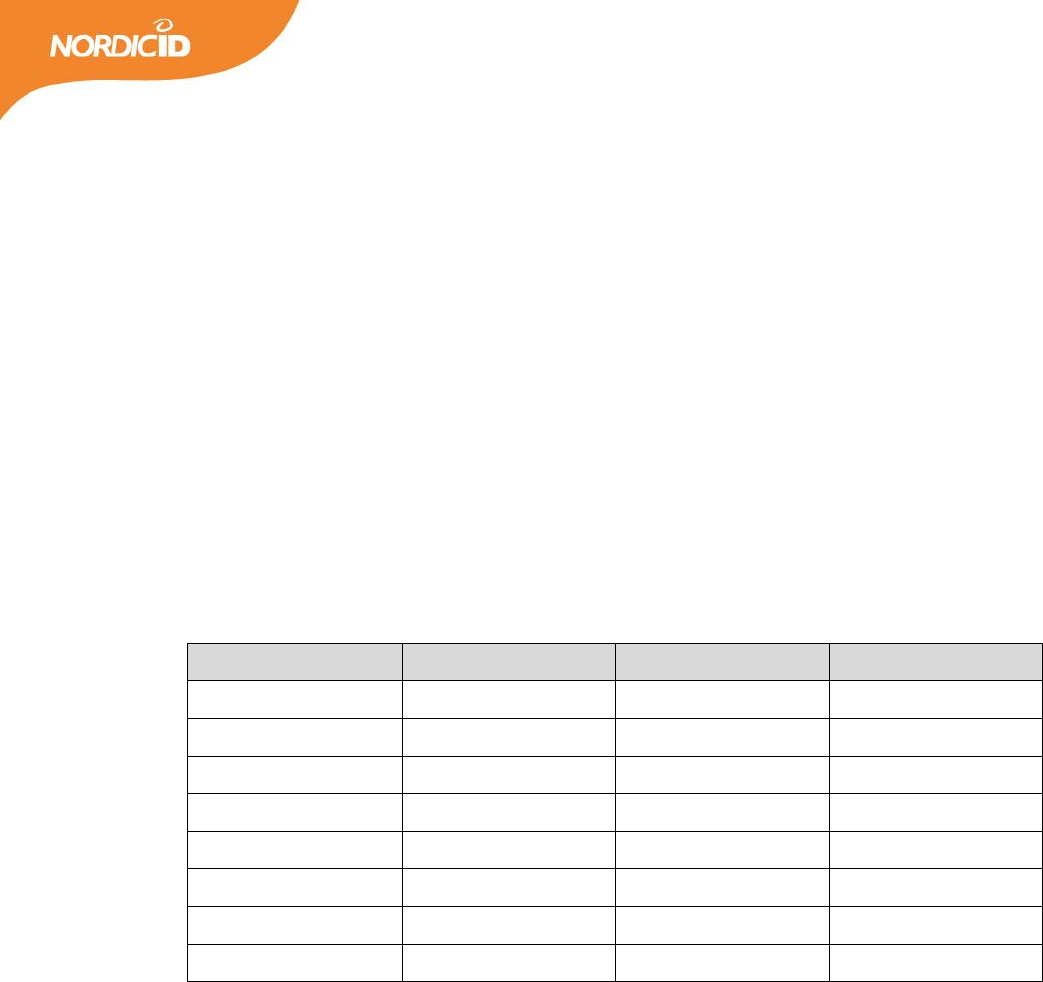
Table 16. Guideline settings to be used with different tag populations.
Settings
Tag population
Simultaneously in the field
Session 0, auto Q, auto Rounds
1 – 100
1 – 100
Session 1, auto Q, Rounds 1
100 – 1 000
under 500
Session 2/3, auto Q, Rounds 1
100 – 1 000
over 500
Session 2/3, auto Q, Rounds 1
over 1 000
over 500
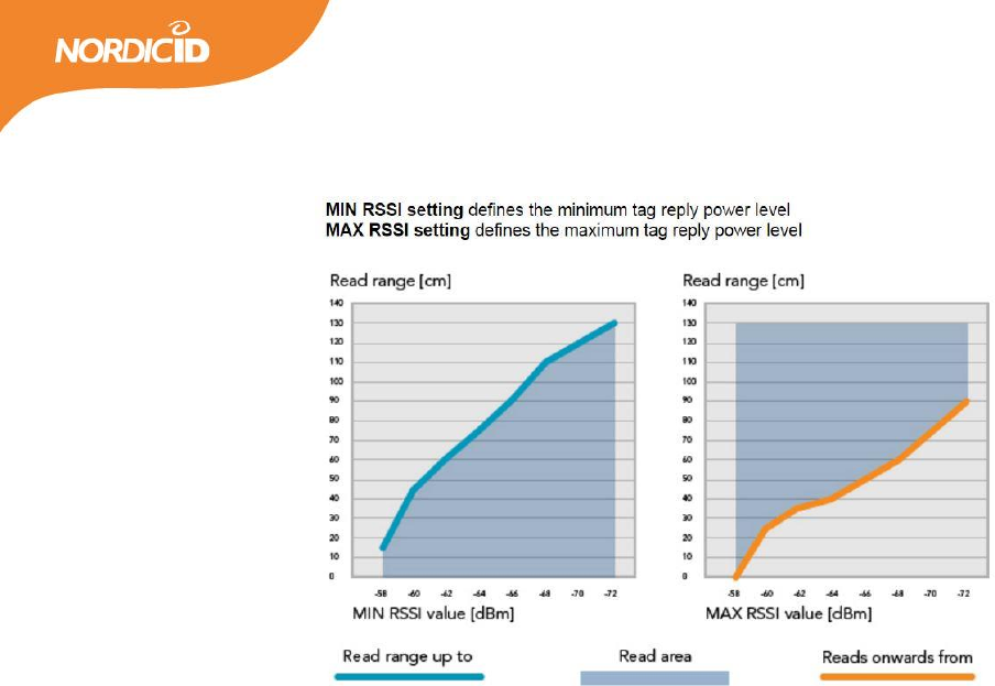
6.5 RSSI FILTERS
NUR-10W module has internal RSSI filters which can be used to limit the read area. By applying the filters
you can set the limits which tag replay must met in order to be registered. MIN RSSI –value means that tag
replay signal needs to be equal or stronger then the defined value. Otherwise tag is not read. MAX RSSI
value in other hand means that signal strength must be lower than the filter value.
24
2016-03-18
NUR-10W HW Implementation Guide v1.4
Figure 8. Read range limited by RSSI filter (100mW TX power and 0dBi antenna gain)
6.6 DYNAMIC POWER SAVE MODES
NUR-10W module has power save modes which can be enabled via SW API. By default the power save is ON
with depth of 100ms. Other depths are 500ms and 1000ms. The power save mode works in a way that
when module reads continuously (applies only when using inventory stream -command) it goes to sleep if
there is no tags in the field. The sleep time is defined by the depth value. After the sleep period it starts to
read again. If there is one or more tags in the field the module will not go into sleep.
25
2016-03-18
NUR-10W HW Implementation Guide v1.4
7 GPIO CONFIGURATIONS
NUR-10W has 5 programmable GPIOs. All of them can be used as an input or output. They can be also
configured to have different predefined functions.
7.1 INPUT / OUTPUT
All GPIOs can be configured via SW API to be inputs or outputs. IO voltage level is 3.3V and maximum
source current is 3mA and sink current 6mA. When configured as input SW API can check what the state
(high / low) of the GPIO pin is. When GPIO is configured as an output the SW API can drive the GPIO pin to
high or low.
7.2 PREDEFINED FUNCTIONS
Table 17. NUR-10W module GPIOs options.
RFON (GPIO type: OUTPUT)
When GPIO is configured as “RFON” it drives high state always when power amplifier is turned on. This
function can be used for example driving LED indicator.
RFIDREAD (GPIO type: OUTPUT)
When “RFIDREAD” function is selected will GPIO pin drive high for a short period of time after a timeout has
surpassed after last successful tag reading. The timeout can be defined as a parameter for the function. If
no tags were successfully read and the timeout was surpassed the pin will drive high three times. This
I/O
Function
Action
Trigger
Output
-
-
-
Output
RFON
-
-
Output
RFIDREAD
-
-
Output
Beeper
-
-
Output
Antenna control 1
-
-
Output
Antenna control 2
-
-
Input
-
-
-
Input
-
Notify
rising/falling/both
Input
-
Scantag
rising/falling/both
Input
-
Inventory
rising/falling/both

26
2016-03-18
NUR-10W HW Implementation Guide v1.4
function can be used for example driving a LED indicator. Note that this function requires a “scan tag” or
“inventory” trigger from another GPIO pin set as an input.
Beeper (GPIO type: OUTPUT)
When “beeper” function is used will GPIO pin drive high for a short period of time after a timeout has
surpassed after last successful tag reading. The timeout can be defined as a parameter for the function. If
no tags were successfully read and the timeout was surpassed the pin will drive high three times. This
function can be used for example driving a beeper. Note that this function requires a “scan tag” or
“inventory” trigger from another GPIO pin set as an input. GPIO is high also when sending a beep command
(13) over the SW API.
Inventory (GPIO type: INPUT)
When “inventory” function is selected will reader start reading when it is triggered by selected GPIO.
Triggering can be configured to be from falling / rising / both edges. Reader will read as long as it finds new
tags. Time interval between end of reading and last found tag can be configured.
Scantag (GPIO type: INPUT)
When GPIO is configured as “scan tag” reader will perform just one read. Triggering can be configured to be
from falling / rising / both edges
Notify (GPIO type: INPUT)
When GPIO is configured as “notify” will reader send notification to Host application when triggered by
selected GPIO. Triggering can be configured to be from falling / rising / both edges
Antenna control 1 (GPIO type: OUTPUT)
When GPIO is configured as “antenna control 1” it can be used for controlling external multiplexer on the
Host board to switch between two antennas. Via the SW API it’s possible to select which antennas are
enabled and used or let the module automatically switch between them.
Table 18. 2 Port antenna control truth table.
Case (selected antenna)
antenna control 1
0 (antenna 1)
low
1 (antenna 2)
high
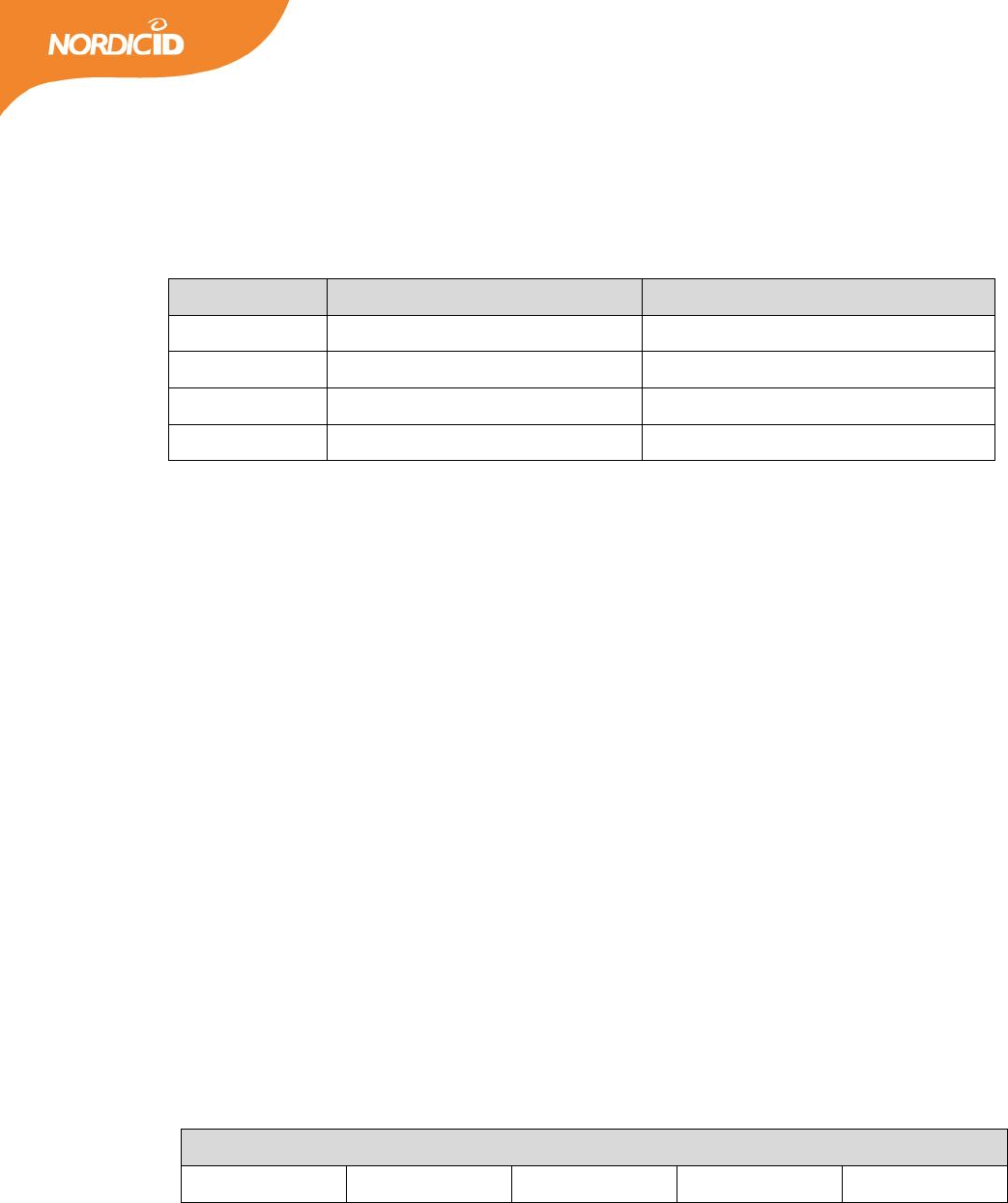
Antenna control 1 & 2 (GPIO type: OUTPUT)
If you want to connect up to 4 antennas and multiplex those using NUR-10W module you need to configure
2 GPIOs to control the antenna switch. In this case you define one GPIO to be “antenna control 1” and

27
2016-03-18
NUR-10W HW Implementation Guide v1.4
second one to be “antenna control 2”. Via the SW API it’s possible to select which of the connected
antennas are enabled and used or let the module automatically switch between them.
Table 19. 4 Port antenna control truth table.
8 DIAGNOSTIC FUNCTIONS
8.1 REFLECTED POWER MEASUREMENTS
This measurement can be used to check what is the matching of the antenna(s) and feed line(s). When this
function is triggered will NUR-10W module put carrier wave ON at full power and then measure the
absolute power level that is coming to receiver port. Attenuation in the RX-line is 11 dB between the
measuring point and RF-pin.
Leakage cancelation circuitry will try to cancel the self jammer signal reflecting back from the antenna or
coming directly from coupler. So this value cannot be used to calculate the absolute antenna S11 value. For
good performance reflected power value should be below zero and lower then -10dBm means almost
perfect isolation between transmitter and receiver
8.2 CHANNEL SCANNER
This function can be used to monitor the interferences in the current frequency band. It is also useful if you
want to check if some fixed channel is in use. When you trigger this function NUR-10W will scan all the
channels in current region and return the RSSI-value of each channel. Returned values are absolute power
levels in receiver. Loss between RF pin and receiver is 11 dB so actual values are about 11dB higher.
8.3 RECEIVED SIGNAL STRENGTH (RSSI)
When reading a tag NUR-10W module also returns received signal strength indication values if wanted. Two
values are returned per one tag. One is the absolute power level (dBm) and second is the scaled power level
Case (selected antenna)
antenna control 1
antenna control 2
0 (antenna 1)
low
low
1 (antenna 2)
high
low
2 (antenna 3)
low
high
3 (antenna 4)
high
high
28
2016-03-18
NUR-10W HW Implementation Guide v1.4
value of the tags backscatter signal. NUR-10W module automatically adjusts receiver according to output
power levels. Causing that maximum and minimum absolute RSSI power levels will vary depending from the
used output power levels. That is why scaled RSSI value is also available. Scale is 0 – 100.
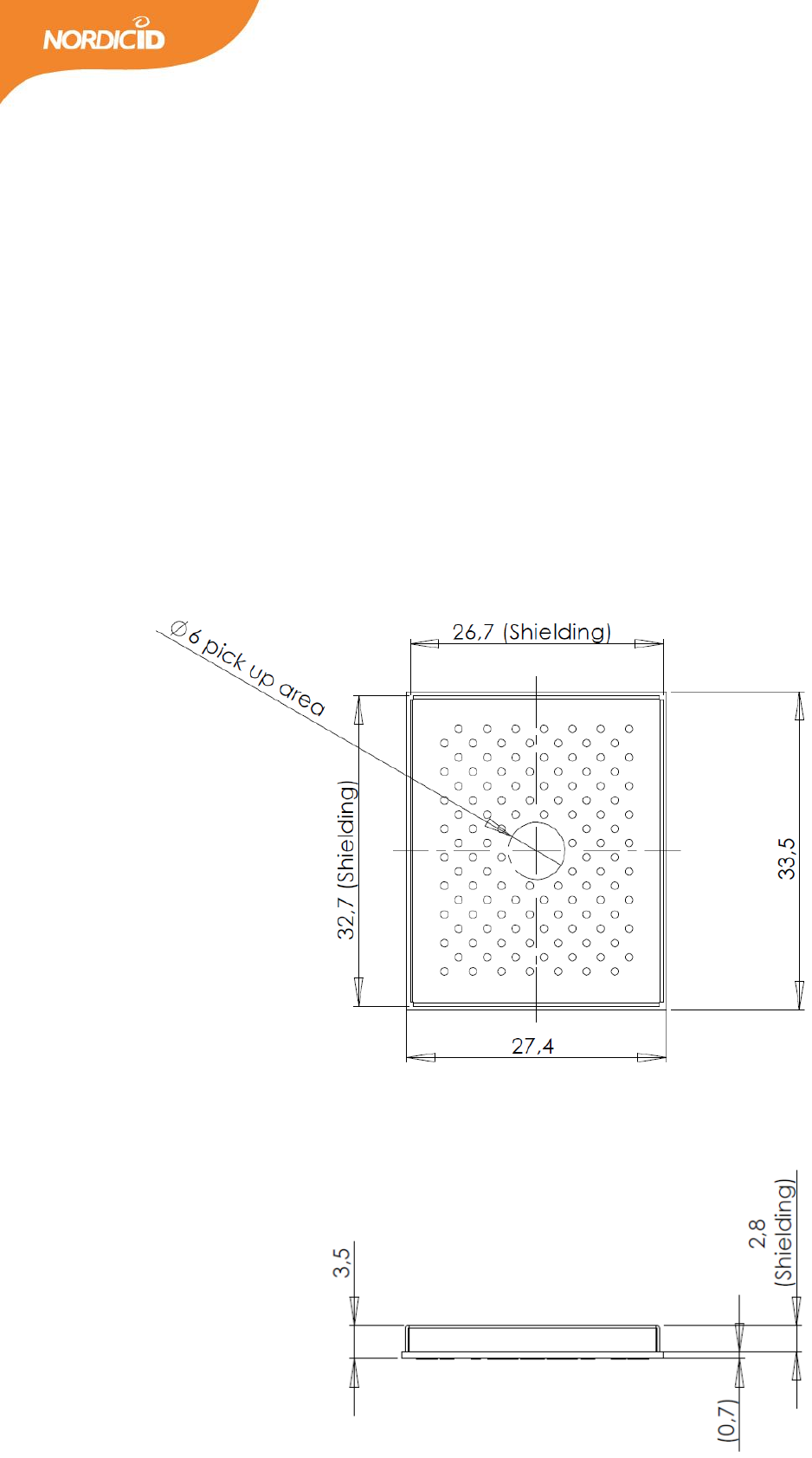
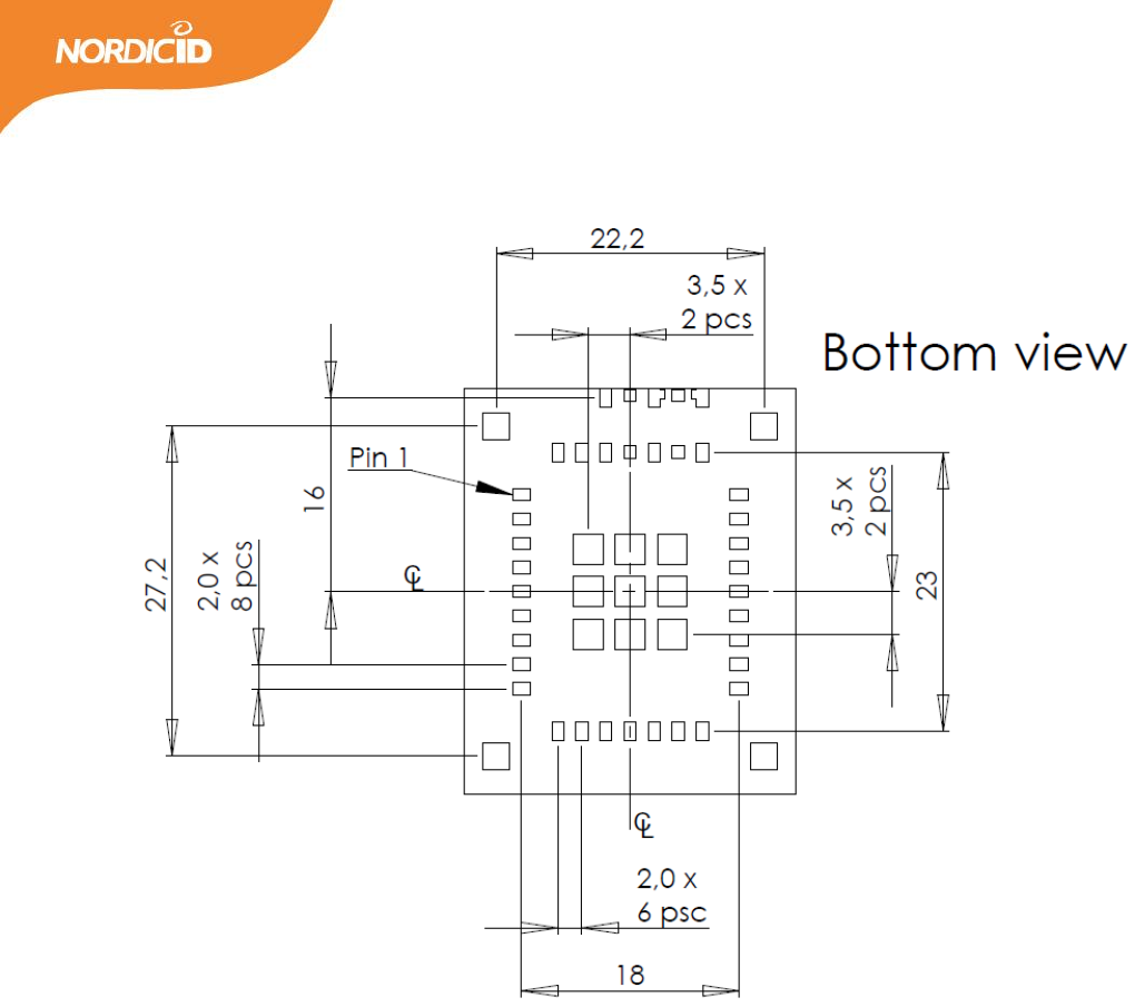
9 DIMENSIONS
9.1 MECHANICAL DIMENSIONS
29
2016-03-18
NUR-10W HW Implementation Guide v1.4
30
2016-03-18
NUR-10W HW Implementation Guide v1.4
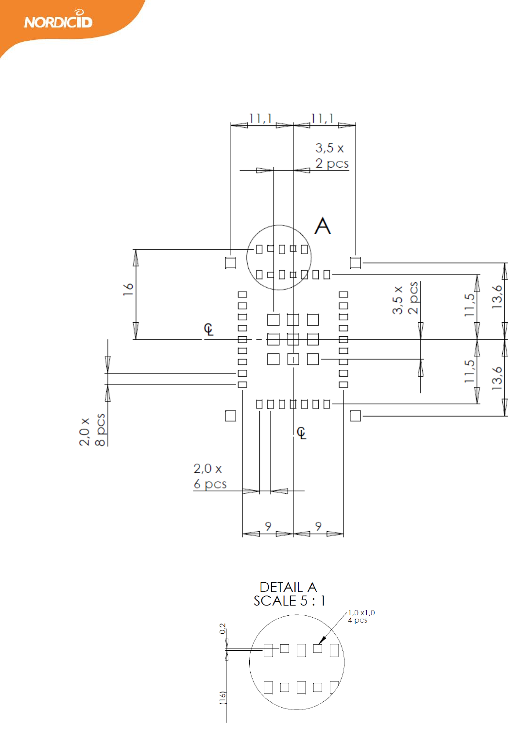
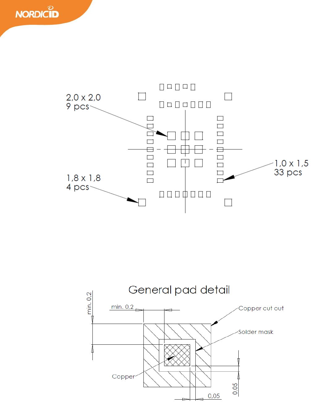
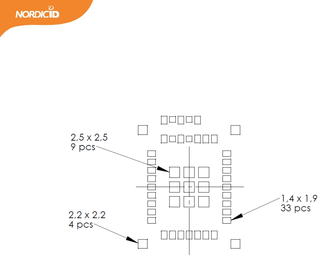
9.2 LAND PATTERN
31
2016-03-18
NUR-10W HW Implementation Guide v1.4
32
2016-03-18
NUR-10W HW Implementation Guide v1.4
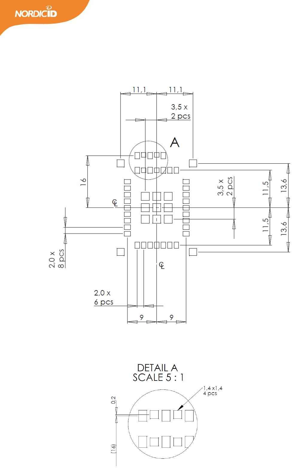
9.3 PASTE STENCIL
33
2016-03-18
NUR-10W HW Implementation Guide v1.4
34
2016-03-18
NUR-10W HW Implementation Guide v1.4
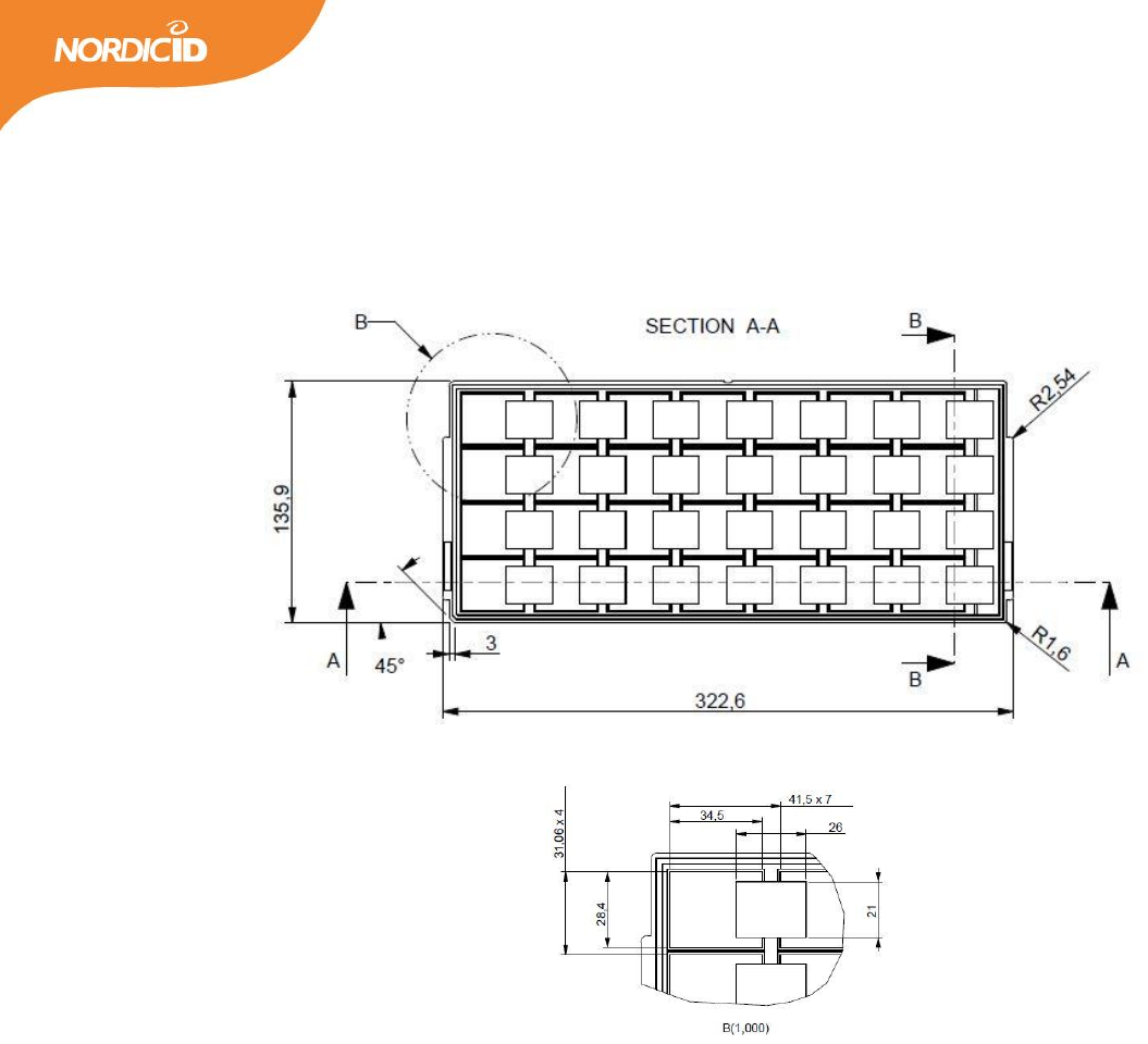
9.4 PACKING TRAY DIMENSIONS
All measures are in mm.
35
2016-03-18
NUR-10W HW Implementation Guide v1.4
10 SMT ASSEMBLY PROCESS AND THERMAL PROCESSING
NUR-10W module contains single sided assembly of SMT components reflow-soldered on multilayer HDI
(high density interconnections) glass-fiber re-enforced epoxy printed board. The bottom side terminations
are ENIG (NiP/Au) plated. Soldering alloy used for attaching module components is eutectic SnAgCu.
Module internal components soldering has been optimized for minimal thermal stress.
NUR-10W modules shall be delivered in a special tray packing to protect modules against mechanical, ESD
and moisture related stresses. Due to high density interconnections technology, module total water content
have to be below 0.1%-w prior to any thermal processing above water boiling point.
The board assembly process of NUR module on motherboard will introduce re-flow of module components.
Thus, to avoid degradation of solder joint interfaces, the module has to be stored and soldered according to
the guidelines given below.
10.1 STORAGE CONDITIONS
Long-term storage
Store modules in unopened vacuum packs in a dry cabinet under following environmental conditions
Temperature
+15…+27°C (optimal)
Temperature gradient
max. 2°C/hour
Relative humidity
<15% within specified temperature range
Opened and broken packages have to be re-sealed. If open time (floor life out of pack) has been
exceeded, or moisture content detected, modules have to be baked prior to re-sealing vacuum pack.
Short-term storage (typically same as production environment)
Temperature
+20…+27°C
Temperature gradient
max. 2°C/hour
Relative humidity
<15% within specified temperature range
Modules may be stored in a dry cabinet without protective packing according to IPC/JEDEC J-STD-
033B.1, table 7-1.
36
2016-03-18
NUR-10W HW Implementation Guide v1.4
MSL level and open time
MSL level
5
Open time (floor life out of the
bag)
48h
10.2 SOLDERING PROCESS
Boundary conditions
Acceptable soldering methods
Convection reflow in air or nitrogen atmosphere
Condensation reflow soldering (vapor phase)
Recommended stencil thickness
125um ±10um
Pad design on motherboard
See recommended pad pattern
Stencil openings
See recommended stencil pattern
Recommended solder alloy
SnAg3.8±0.2Cu0.7±0.2
Note! If using under-eutectic solder alloys, such as
SAC305, it may be necessary to increase reflow
peak temperature by 5-10°C, due to higher mp.
and lower fluidity of non-eutectic SnAgCu alloys.
This will increase thermal stress to module and
motherboard greatly.
Convection reflow oven heater
configuration
Double sided heating required in reflow,
recommended in preheating zones.
Maximum absorbed moisture
content prior to thermal
processing
0.1%-w (Test method IPC-TM-650, 2.6.28)
Moisture content and/or moisture absorption
rate, Printed Board
Recommended moisture
reduction condition
+60°C/12h vacuum pack removed during drying,
re-seal after drying, unless modules will be used
within allowed open time after drying
Moisture and solvent
contamination
No moisture or solvent contamination allowed in
solder paste or on solderable surfaces
Recommended reflow conditions
Preheating phase
-max. duration 180s
-end temperature 190-200°C

37
2016-03-18
NUR-10W HW Implementation Guide v1.4
-delta T on assembly max. 10°C at end of
preheating
Soldering phase
-total duration 190s
-max. time above 217°C (mp.) 30s
-Tpeak max. 235°C, measured at module bottom
-Tpeak max. 225°C, measured at motherboard
surface, under module
Cooling
Two-stage, double sided cooling recommended
1st stage: 2-5°C/s cooling until melting point
2nd stage: 1-3°C/s after melting point

38
2016-03-18
NUR-10W HW Implementation Guide v1.4
11 REGULATORY AGENCIES INFORMATION
When OEM prefers to leverage Nordic ID’s grants and certifications of the NUR-10W UHF RFID module, the
host device documentation shall include regulatory compliance information on the NUR-10W module.
Corresponding to the applicable regulatory agencies the following sections outline regulatory compliance
information needed in the user documentation and external labels for the host devices into which the NUR-
10W is integrated.
When leveraging Nordic ID’s grants and certifications, antenna shall be taken into account in view of the
fact that the NUR-10W module has met the essential regulatory requirements with the antennas listed in
the context of particular regulatory compliance information (Approved Antennas). Using the antenna that is
an approved one, OEM integrator may demonstrate with less effort that the device with the integrated
NUR-10W module is in compliance with the requirements.
11.1 EUROPEAN UNION AND EFTA COUNTRIES
USER’S GUIDE REQUIREMENTS
This apparatus is in compliance with the essential requirements of the R&TTE Directive 1999/5/EC. In order
to prove presumption of conformity with the essential requirements of the R&TTE Directive 1999/5/EC the
following requirements and test methods have been applied to the apparatus:
article 3.2: ETSI EN 302 208 v1.4.1
Radio spectrum matters for Radio Frequency Identification (RFID) equipment operating in the band
865 MHz to 868 MHz with power levels up to 2W
article 3.1b: ETSI EN 301 489-1 v1.9.1
Common ElectroMagnetic Compatibility (EMC) requirements
article 3.1b: ETSI EN 301 489-3 v1.4.1
Specific ElectroMagnetic Compatibility (EMC) conditions for Short-Range Devices (SRD) operating on
frequencies between 9 kHz and 40 GHz
article 3.1a: EN 60950-1:2005
General requirements for Safety of Information Technology Equipment
This apparatus is in compliance with EU Directive 2003/95/EC, Reduction of Hazardous Substances (RoHS).

39
2016-03-18
NUR-10W HW Implementation Guide v1.4
Česky
[Czech]
[name of manufacture] tímto prohlašuje, že tento [type of apparatus] je ve shodě sezákladními požadavky a
dalšími příslušnými ustanoveními směrnice1999/5/ES.
Dansk
[Danish]
Undertegnede [name of manufacture] erklærer herved, at følgende udstyr [type of apparatus] overholder
de væsentlige krav og øvrige relevante krav i direktiv 1999/5/EF.
Deutsch
[German]
Hiermit erklärt [name of manufacture], dass sich das Gerät [type of apparatus] in Übereinstimmung mit den
grundlegenden Anforderungen und den übrigen einschlägigen Bestimmungen der Richtlinie 1999/5/EG
befindet.
Eesti
[Estonian]
Käesolevaga kinnitab [name of manufacture] seadme [type of apparatus] vastavust direktiivi 1999/5/EÜ
põhinõuetele ja nimetatud direktiivist tulenevatele teistele asjakohastele sätetele.
English
Hereby, [name of manufacture], declares that this [type of apparatus] is in compliance with the essential
requirements and other relevant provisions of Directive 1999/5/EC.
Español
[Spanish]
Por medio de la presente [name of manufacture] declara que el [type of apparatus] cumple con los
requisitos esenciales y cualesquiera otras disposiciones aplicables o exigibles de la Directiva 1999/5/CE.
Ελληνική
[Greek]
ΜΕ ΤΗΝ ΠΑΡΟΥΣΑ [name of manufacture] ΔΗΛΩΝΕΙ ΟΤΙ [type of apparatus] ΣΥΜΜΟΡΦΩΝΕΤΑΙ ΠΡΟΣ ΤΙΣ
ΟΥΣΙΩΔΕΙΣ ΑΠΑΙΤΗΣΕΙΣ ΚΑΙ ΤΙΣ ΛΟΙΠΕΣ ΣΧΕΤΙΚΕΣ ΔΙΑΤΑΞΕΙΣ ΤΗΣ ΟΔΗΓΙΑΣ 1999/5/ΕΚ.
Français
[French]
Par la présente [name of manufacture] déclare que l'appareil [type of apparatus] est conforme aux
exigences essentielles et aux autres dispositions pertinentes de la directive 1999/5/CE.

40
2016-03-18
NUR-10W HW Implementation Guide v1.4
Italiano
[Italian]
Con la presente [name of manufacture] dichiara che questo [type of apparatus] è conforme ai requisiti
essenziali ed alle altre disposizioni pertinenti stabilite dalla direttiva 1999/5/CE.
Latviski
[Latvian]
Ar šo [name of manufacture] deklarē, ka [type of apparatus] atbilst Direktīvas 1999/5/EK būtiskajām
prasībām un citiem ar to saistītajiem noteikumiem.
Lietuvių
[Lithuanian]
Šiuo [name of manufacture] deklaruoja, kad šis [type of apparatus] atitinka esminius reikalavimus ir kitas
1999/5/EB Direktyvos nuostatas.
Nederlands
[Dutch]
Hierbij verklaart [name of manufacture] dat het toestel [type of apparatus] in overeenstemming is met de
essentiële eisen en de andere relevante bepalingen van richtlijn 1999/5/EG.
Malti
[Maltese]
Hawnhekk, [name of manufacture], jiddikjara li dan [type of apparatus] jikkonforma mal-ħtiġijiet essenzjali
u ma provvedimenti oħrajn relevanti li hemm fid-Dirrettiva 1999/5/EC.
Magyar
[Hungarian]
Alulírott, [name of manufacture] nyilatkozom, hogy a [type of apparatus] megfelel a vonatkozó alapvetõ
követelményeknek és az 1999/5/EC irányelv egyéb elõírásainak.
Polski
[Polish]
Niniejszym [name of manufacture] oświadcza, że [type of apparatus] jest zgodny z zasadniczymi wymogami
oraz pozostałymi stosownymi postanowieniami Dyrektywy 1999/5/EC.
Português
[Portuguese]

41
2016-03-18
NUR-10W HW Implementation Guide v1.4
[name of manufacture] declara que este [type of apparatus] está conforme com os requisitos essenciais e
outras disposições da Directiva 1999/5/CE.
Slovensko
[Slovenian]
[name of manufacture] izjavlja, da je ta [type of apparatus] v skladu z bistvenimi zahtevami in ostalimi
relevantnimi določili direktive 1999/5/ES.
Slovensky
[Slovak]
[name of manufacture] týmto vyhlasuje, že [type of apparatus] spĺňa základné požiadavky a všetky príslušné
ustanovenia Smernice 1999/5/ES.
Suomi
[Finnish]
[name of manufacture] vakuuttaa täten että [type of apparatus] tyyppinen laite on direktiivin 1999/5/EY
oleellisten vaatimusten ja sitä koskevien direktiivin muiden ehtojen mukainen.
Svenska
[Swedish]
Härmed intygar [name of manufacture] att denna [type of apparatus] står i överensstämmelse med de
väsentliga egenskapskrav och övriga relevanta bestämmelser som framgår av direktiv 1999/5/EG.
LABELING REQUIREMENTS
The 'CE' marking must be in a visible area on the OEM product.
APPROVED ANTENNAS
Maximum allowed ERP power is 33dBm. NUR-10W has output power of 30dBm. Meaning that 5dBi is the
maximum allowed antenna gain without cable losses.
Formula how to calculate maximum allowed antenna gain:
30 dBm – 2.15 (dipole gain) + [antenna gain dBi] – [cable attenuation dB] < 33dBm
Beamwidth restrictions:
For transmissions ≤500 mW e.r.p. there shall be no restriction on beamwidth.
For transmissions of > 500 mW e.r.p. to ≤ 1 000 mW e.r.p. beamwidths shall be ≤ 180º
For transmissions of > 1 000 mW e.r.p. to 2 000 mW e.r.p. beamwidths shall be ≤ 90º

42
2016-03-18
NUR-10W HW Implementation Guide v1.4
11.2 FCC
This equipment has been tested and found to comply with the limits for a Class B digital device, pursuant to
Part 15 of the FCC Rules. These limits are designed to provide reasonable protection against harmful
interference in a residential installation. This equipment generates uses and can radiate radio frequency
energy and, if not installed and used in accordance with the instructions, may cause harmful interference to
radio communications. However, there is no guarantee that interference will not occur in a particular
installation. If this equipment does cause harmful interference to radio or television reception, which can
be determined by turning the equipment off and on, the user is encouraged to try to correct the
interference by one of the following measures:
Reorient or relocate the receiving antenna.
Increase the separation between the equipment and receiver.
Connect the equipment into an outlet on a circuit different from that to which the receiver is
connected.
Consult the dealer or an experienced radio/TV technician for help.
This device complies with Part 15 of the FCC Rules. Operation is subject to the following two conditions: (1)
This device may not cause harmful interference, and (2) this device must accept any interference received,
including interference that may cause undesired operation.
Note
Integrator of the module cannot change the region setting of the module. When FCC region is
set, the module operates in frequency band of 902 – 928Mhz.
FCC Caution: Any changes or modifications not expressly approved by the party responsible for compliance
could void the user's authority to operate this equipment.
This NUR-10W transmitter module is authorized to be used in other devices only by OEM Integrators under
the following conditions:
1. The module can be used only with the approved antenna types (see the section of Approved antennas
below) having the antenna gains of 5dBi and 6dBi at the maximum. The approved antennas need the
following minimum separation distances when installed: the antenna with the gain of 6dBi requires a
minimum separation distance of 23 cm and the antenna having the gain of 5dBi requires a minimum
separation distance of 21 cm. The antenna must be installed such that the minimum separation distance
can be maintained between the antenna (radiator) and user’s/nearby people’s body at all times.

43
2016-03-18
NUR-10W HW Implementation Guide v1.4
If the antenna being one of the approved antenna types has lower antenna gain than the type’s maximum
one, the minimum separation distance (d in cm) can be calculated by giving the EIRP (in mW) of the
configuration and the maximum permissible exposure (S = 0.61 mWcm-2) to the following formula: d =
√(EIRP/(4πS)). However, despite the fact that the result of the calculation can be below 20 cm, the
separation distance of 20 cm is always the minimum.
The EIRP (EIRPdBm = Po - Ll + G ) needed for the calculation of minimum separation distance consists of the
following factors:
Po = (Maximum rated output power) = 30.00 (dBm)
Ll = (Line losses) = known value (dB)
G = (Antenna gain) = known value (dBi)
2. The NUR-10W transmitter module must not be integrated into a multi-transmitter end product with any
other transmitter being capable of transmitting simultaneously with the NUR-10W, except with those
transmitters that are within the limits shown in the NUR-10W filing.
3. The transmitter module can only be used with a host antenna circuit trace layout design in strict
compliance with the OEM instructions provided.
When the conditions above are met, typically no radio transmitter testing of NUR-10W is required.
However, the OEM integrators have responsibility for testing their end-product for other compliance
requirements, for example digital device emissions, PC peripheral requirements.
The antenna used with the NUR-10W transmitter module shall comply with the gain limit of 6 dBi. The
antennas having higher gain may be used, if cable loss compensates the exceeded antenna gain. For
example, 2dB antenna cable loss reduces the EIRP of the configuration so that 8dBi antenna may be used. If
the cable loss does not cancel out the exceeded gain then the transmitter’s conducted output power shall
be reduced so that the EIRP of the configuration is kept inside the limits of 4W.
Note
In the event that these conditions can’t be met (for certain configurations or co-location with another
transmitter), then the FCC authorization is no longer considered valid and the FCC ID can’t be used on
the final product. In these circumstances, the OEM integrator will be responsible for reevaluating the
end product (including the transmitter) and obtaining a separate FCC authorization.
The OEM integrator has to be aware not to provide information to the end user regarding how to install or
remove this RF module in the user manual of the end product.

44
2016-03-18
NUR-10W HW Implementation Guide v1.4
For the User’s Guide the required FCC statements outlined in the User’s Guide Requirements section must
be in a prominent location.
USER’S GUIDE REQUIREMENTS
The texts in quotation marks below are the required FCC statements in the user’s guide. The note given in
brackets is not an FCC statement but it gives the required information on the first required FCC statement.
“To comply with FCC’s RF radiation exposure requirements, the antenna(s) used for this transmitter must
be installed such that a minimum separation distance of ‘d’ cm is maintained between the radiator
(antenna) & user’s/nearby people’s body at all times and must not be co-located or operating in
conjunction with any other antenna or transmitter.”
(Note: Use the following formula to find the ‘d’ in cm: d = √(EIRP/(4πS)); let ‘EIRP’ have the maximum EIRP
(in mW) of your transmitter configuration, and let ‘S’ have the 0.61 (in mW/cm2) value. In addition, the ‘d’
value cannot be below 20cm, although the formula would yield smaller minimum separation distance d. See
also the EIRP factors mentioned above.)
“This device complies with Part 15 of the FCC Rules”
“Any changes or modifications to the transmitting module not expressly approved by
Nordic ID Oy could void the user’s authority to operate this equipment”
LABELING REQUIREMENTS
The end product must be labeled with the following identification information in a visible area:
“Contains Transmitter Module FCC ID: SCCNUR10W”
or
“Contains FCC ID: SCCNUR10W”
APPROVED ANTENNAS
Option 1:
Manufacturer: Nordic ID
Antenna Description: 4 Patch antenna-array
Frequency range: 902 – 928 MHz

45
2016-03-18
NUR-10W HW Implementation Guide v1.4
Manufacturer Part Number: ARx5_antenna
Gain: 6dBi
Option 2:
Manufacturer: Nordic ID
Antenna Description: Cross Dipole antenna with reflector
Frequency range: 902 – 928 MHz
Manufacturer Product Name: Medea_ACD_antenna
Gain: 5dBi
Option 3:
Manufacturer: TBD
Antenna Description: TBD
Frequency range: TBD
Manufacturer Product Name: TBD
Gain: TBD
11.3 INDUSTRY CANADA
This device complies with Industry Canada licence-exempt RSS standard(s). Operation is
subject to the following two conditions: (1) this device may not cause interference, and (2)
this device must accept any interference, including interference that may cause
undesired operation of the device.
Under Industry Canada regulations, this radio transmitter may only operate using an antenna of a
type and maximum (or lesser) gain approved for the transmitter by Industry Canada. To reduce
potential radio interference to other users, the antenna type and its gain should be so chosen that
the equivalent isotropically radiated power (e.i.r.p.) is not more than that necessary for successful
communication.
To leverage the Nordic ID’s IC grant, the device with the integrated NUR-10W module shall be met the
following conditions:
1. The antennas being the approved types with the maximum gain of 5dBi and of 6dBi shall be installed so
that the device’s user or nearby people or passing people cannot compromise the minimum separation
distance of 30cm and of 34cm, respectively, in any situation. If the antenna being one of the approved

46
2016-03-18
NUR-10W HW Implementation Guide v1.4
antenna types has lower antenna gain than the type’s maximum one, the minimum separation distance (d in
cm) can be calculated by giving the EIRP of the configuration and the exposure limit (S = 0.276676 mWcm-2)
to the following formula: d = √(EIRP/(4πS)). However, despite the fact that the result of the calculation can
be below 20 cm, the separation distance of 20 cm is always the minimum.
The EIRP (EIRPdBm = Po - Ll + G ) needed for the calculation of minimum separation distance consists of the
following factors:
Po = (Maximum rated output power) = 30.00 (dBm)
Ll = (Line losses) = known value (dB)
G = (Antenna gain) = known value (dBi)
2. The antenna(s) used with the NUR-10W module must not be collocated in conjunction with any other
transmitter or its antenna that is capable of transmitting at the same time, except the transmitter-antenna
configurations that are within the limits of the NUR-10W’s IC grant.
3. The design of an antenna circuit trace layout in a host shall comply with the OEM design instructions
provided.
When the conditions above are met, typically no transmitter testing is required, although the OEM
integrator shall demonstrate that the end-product is in compliance with the other regulatory requirements.
There is no user’s documentation requirements other than that the required FCC statements outlined in the
FCC section are in a prominent place in the user’s guide.
Note
User of the module cannot change the region setting of the module. When FCC region is set, the
module operates in frequency band of 902 – 928Mhz.
LABELLING REQUIREMENTS FOR THE HOST DEVICE
The end product must be labeled with the following identification information in a visible area:
“Contains IC: 5137A-NUR10W”
CERTIFIED ANTENNAS
This radio transmitter 5137A-NUR10W has been approved by Industry Canada to operate with the antenna
types listed below with the maximum permissible gain and required antenna impedance for each antenna

47
2016-03-18
NUR-10W HW Implementation Guide v1.4
type indicated. Antenna types not included in this list, having a gain greater than the maximum gain
indicated for that type, are strictly prohibited for use with this device.
Option 1:
Manufacturer: Nordic ID
Antenna Description: 4 Patch antenna-array
Frequency range: 902 – 928 MHz
Manufacturer Part Number: ARx5_antenna
Gain: 6dBi
Option 2:
Manufacturer: Nordic ID
Antenna Description: Cross Dipole antenna with reflector
Frequency range: 902 – 928 MHz
Manufacturer Product Name: Medea_ACD_antenna
Gain: 5dBi
11.4 INDUSTRIE CANADA
Le présent appareil est conforme aux CNR d'Industrie Canada applicables aux appareils radio
exempts de licence. L'exploitation est autorisée aux deux conditions suivantes : (1) l'appareil ne
doit pas produire de brouillage, et (2) l'utilisateur de l'appareil doit accepter tout brouillage
radioélectrique subi, même si le brouillage est susceptible d'en compromettre le fonctionnement.
Conformément à la réglementation d'Industrie Canada, le présent émetteur radio peut
fonctionner avec une antenne d'un type et d'un gain maximal (ou inférieur) approuvé pour
l'émetteur par Industrie Canada. Dans le but de réduire les risques de brouillage radioélectrique
à l'intention des autres utilisateurs, il faut choisir le type d'antenne et son gain de sorte que la
puissance isotrope rayonnée équivalente (p.i.r.e.) ne dépasse pas l'intensité nécessaire à
l'établissement d'une communication satisfaisante..
Le module émetteur NUR-10W estautorisé à êtreutilisé avec d’autresappareilsuniquement par des
intégrateurs OEM sous les conditions suivantes :

48
2016-03-18
NUR-10W HW Implementation Guide v1.4
1. Les antennes, qui seront des types approuvés avec le gain maximal de 5 dBi et de 6 dBi, seront installées de
telle sorte que l’utilisateur de l’appareil ou les personnes à proximité ou les personnes de passage ne
pourront compromettre la distance minimale de séparation de 30 cm et de 34 cm, respectivement, en
aucune circonstance. Si l’antenne, qui sera un des types d’antennes approuvés, a un gain d’antenne inférieur
à celui maximal du type, la distance minimale de séparation (d en cm) pourra être calculée en donnant la PIRE
de la configuration et la limite d’exposition (S = 0,276676 mWcm-2)suivante : d = √(PIRE/(4πS)). Cependant,
en dépit du fait que le résultat du calcul pourra être inférieur à 20 cm, la distance de séparation de 20 cm
devra toujours constituer le minimum.
La PIRE (PIREdBm = Po - Ll + G) nécessaire pour le calcul de la distance minimale de séparation se compose des
facteurs suivants :
Po = 30.00 (dBm)
Ll (Pertes en lignes) = valeur connue (dB)
G (Gain d’antenne) = valeur connue (dBi)
2. Le module émetteur ne doit pas êtrecolocalisé avec d´autre(s) transmetteur(s), saufsice(s) dernier(s)
répond(ent) avec ceux qui sontdans les limitesindiquéesdansl´application de NUR-10W.
3. Le module émetteurpeutêtreuniquementutilisé avec unschéma du design de configuration de la piste du
circuit de l’antennehôteenrespectantstrictement les instructions OEM fournies.
Lorsque les conditions ci-dessus sont remplies, aucun test radio de l’émetteur NUR-10W ne sera
généralement nécessaire, même si l’intégrateur OEM devra démontrer que le produit final est en conformité
avec les autres exigences réglementaires.
Il n’existe aucune exigence de documentation de l’utilisateur autre que le fait que les déclarations
obligatoires FCC dans la section FCC soient bien en vue dans le guide de l’utilisateur.
Observation:
L’utilisateur du module ne pourra pas changer les paramètres région du module. Quand le
paramètre région FCC est sélectionné, le module fonctionne sur la bande de fréquence 902-
928Mhz.
EXIGENCES APPLICABLES AUX APPAREILS HÔTES
Le produit fini doit disposer d´étiquette mentionnant les information suivantes d´identification sur une
surface visible:
“Contains IC: 5137A-NUR10W”

49
2016-03-18
NUR-10W HW Implementation Guide v1.4
TYPES D'ANTENNES ACCEPTABLES
Le présent émetteur radio (IC: 5137A-NUR10W) a été approuvé par Industrie Canada pour fonctionner avec
les types d'antenne énumérés ci-dessous et ayant un gain admissible maximal et l'impédance requise pour
chaque type d'antenne. Les types d'antenne non inclus dans cette liste, ou dont le gain est supérieur au
gain maximal indiqué, sont strictement interdits pour l'exploitation de l'émetteur.
Option 1:
Manufacturer: Nordic ID
Antenna Description: 4 Patch antenna-array
Frequency range: 902 – 928 MHz
Manufacturer Part Number: ARx5_antenna
Gain: 6dBi
Option 2:
Manufacturer: Nordic ID
Antenna Description: Cross Dipole antenna with reflector
Frequency range: 902 – 928 MHz
Manufacturer Product Name: Medea_ACD_antenna
Gain: 5dBi